Solar Concentrators
15
F. Muhammad-Sukki, R. Ramirez-Iniguez, S.G. McMeekin, B.G. Stewart & B. Clive International Journal of Applied Sciences (IJAS), Volume (1): Issue (1) 1 Solar Concentrators Firdaus Muhammad-Sukki [email protected] School of Engineering and Computing, Glasgow Caledonian University, Cowcaddens Road, Glasgow, G4 0BA, Scotland, UK Roberto Ramirez-Iniguez [email protected] School of Engineering and Computing, Glasgow Caledonian University, Cowcaddens Road, Glasgow, G4 0BA, Scotland, UK Scott G McMeekin [email protected] School of Engineering and Computing, Glasgow Caledonian University, Cowcaddens Road, Glasgow, G4 0BA, Scotland, UK Brian G Stewart [email protected] School of Engineering and Computing, Glasgow Caledonian University, Cowcaddens Road, Glasgow, G4 0BA, Scotland, UK Barry Clive [email protected] Solar Empower Ltd, 74-75 Brunner Road, London, E17 7NW, England, UK Abstract Solar technology offers great potential in terms of supplying the world’s energy needs. However, its current contribution to the world is still limited. The main factor is related to high initial cost of building the system. This paper will provide an up-to-date review of solar concentrators and their benefits to make solar technology affordable. It will also analyse on some of the existing solar concentrators used in the solar technology for the past four decades. The design and performance of each concentrator will be explained and compared. Keywords: Renewable Energy Resources, Solar Energy, Solar Concentrator
-
Upload
waqas-tariq -
Category
Education
-
view
283 -
download
0
Transcript of Solar Concentrators

F. Muhammad-Sukki, R. Ramirez-Iniguez, S.G. McMeekin, B.G. Stewart & B. Clive
International Journal of Applied Sciences (IJAS), Volume (1): Issue (1) 1
Solar Concentrators
Firdaus Muhammad-Sukki [email protected] School of Engineering and Computing, Glasgow Caledonian University, Cowcaddens Road, Glasgow, G4 0BA, Scotland, UK
Roberto Ramirez-Iniguez [email protected] School of Engineering and Computing, Glasgow Caledonian University, Cowcaddens Road, Glasgow, G4 0BA, Scotland, UK
Scott G McMeekin [email protected] School of Engineering and Computing, Glasgow Caledonian University, Cowcaddens Road, Glasgow, G4 0BA, Scotland, UK
Brian G Stewart [email protected] School of Engineering and Computing, Glasgow Caledonian University, Cowcaddens Road, Glasgow, G4 0BA, Scotland, UK
Barry Clive [email protected] Solar Empower Ltd, 74-75 Brunner Road, London, E17 7NW, England, UK
Abstract
Solar technology offers great potential in terms of supplying the world’s energy needs. However, its current contribution to the world is still limited. The main factor is related to high initial cost of building the system. This paper will provide an up-to-date review of solar concentrators and their benefits to make solar technology affordable. It will also analyse on some of the existing solar concentrators used in the solar technology for the past four decades. The design and performance of each concentrator will be explained and compared. Keywords: Renewable Energy Resources, Solar Energy, Solar Concentrator

F. Muhammad-Sukki, R. Ramirez-Iniguez, S.G. McMeekin, B.G. Stewart & B. Clive
International Journal of Applied Sciences (IJAS), Volume (1): Issue (1) 2
1. INTRODUCTION
Over the last few decades, there have been significant changes in the way people use the world’s energy resources. There has been an increasing effort from governments, industry and academic institutions to find alternative sources of energy and to improve energy efficiency. This, plus an ever growing pressure from different sectors of society to reduce carbon dioxide emissions, has motivates the development of emerging technologies to reduce the dependency on fossil fuels and the optimization of existing systems in order to minimize energy consumption. A lot of countries are now focusing more on renewable energy. In the US, for instance, President Barack Obama has chosen a group of people to run his Energy Department, hailed by the media as the “Green Team”. Besides tackling the climate change, the team is also responsible to venture into new technologies. In 2008 alone, it is reported that the total global investment in renewable energy has reached approximately USD120 billion, led by the US, Spain, China and Germany [1]. Solar energy is one of the alternative energies that has vast potential. It is estimated that the earth receives approximately 1000W/m
2 amount of solar irradiation in a day [2]. Abbot [3] shows that this
amount of irradiation could generate around 85,000TW and estimates that the current global energy consumption is about 15TW. Taking into account the power obtained from all renewable resources as illustrated in Table 1, he concluded that the solar energy alone has the capability to meet the current energy demand. This is confirmed theoretical calculation of Liu et al. [4] who estimates that by harnessing the solar energy from eight different solar power plant sites throughout the world, the energy generated from these plants has the capability to supply more than enough electricity to satisfy the present global energy utilization. These sites are located in the deserts in Southwest Asia, China, Australia, Southern South America, United States and Mexico. There are two ways to produce electricity from the sun [5]. First is by using the concentrating solar thermal system. This is done by focusing the heat from the sun to produce steam. The steam will drove a generator to produce electricity. This type of configuration is normally employed in solar power plants. The other way of generating electricity is through a photovoltaic (PV) cell. This technology will convert the sunlight directly into electricity. This technique is now being widely installed in the residential house and at remote places. It is also contributing to the significant increase in the development of Building Integrated Photovoltaic (BIPV) system.
Energy Source Max. Power (TW)
Total surface solar 85 000
Desert solar 7650
Ocean thermal 100
Wind 72
Geothermal 44
River hydroelectric 7
Biomass 7
Open ocean wave 7
Tidal wave 4
Coastal wave 3
TABLE 1: Power available from renewable resources [2] However, despite numerous efforts done by the government and private sectors, solar energy only contributes to less than 1% of world’s energy demand [6]. Some of the main drawbacks for the solar

F. Muhammad-Sukki, R. Ramirez-Iniguez, S.G. McMeekin, B.G. Stewart & B. Clive
International Journal of Applied Sciences (IJAS), Volume (1): Issue (1) 3
technology are due to the high investment cost and long payback period [7]. For an example, for an installation of a simple solar PV system, around 55%
1 of the total cost comes from the PV module [8]. In
terms of efficiency, only 15% to 30% of the sunlight is converted to electricity, depending on the type of semiconductor used in the PV. The highest efficiency recorded so far is by the Fraunhofer Institute for Solar Energy Systems, at 41.1% [9]. If we could reduce the cost of the PV module, or minimise its usage in the solar cell, while maintaining the same amount of output, it is feasible and affordable to use the solar technology. Solar concentrator is the most favourable solution to this problem [10].
2. SOLAR CONCENTRATORS
2.1 Overview
Solar concentrator is a device that allows the collection of sunlight from a large area and focusing it on a smaller receiver or exit. A conceptual representation of a solar concentrator used in harnessing the power from the sun to generate electricity is shown in Figure 1. The material used to fabricate the concentrator varies depending on the usage. For solar thermal, most of the concentrators are made from mirrors while for the BIPV system, the concentrator is either made of glass or transparent plastic. These materials are far cheaper than the PV material. The cost per unit area of a solar concentrator is therefore much cheaper than the cost per unit area of a PV material. By introducing this concentrator, not only the same amount of energy could be collected from the sun, the total cost of the solar cell could also be reduced. Arizona Public Service has concluded that the most cost-effective PV for commercial application in the future will be dominated by high concentration collector incorporated by high-efficiency cell [11].
FIGURE 1: Generating electricity from the sun, with and without a solar concentrator. Some of the benefits and drawbacks of using the solar concentrators are summarise below. Benefits:
1 This numerical number is based on the installation done for research environment in New Zealand. In reality, the cost varies
depending on the type of PV material used, labour, maintenance etc.
F. Muhammad-Sukki, R. Ramirez-Iniguez, S.G. McMeekin, B.G. Stewart & B. Clive
International Journal of Applied Sciences (IJAS), Volume (1): Issue (1) 4
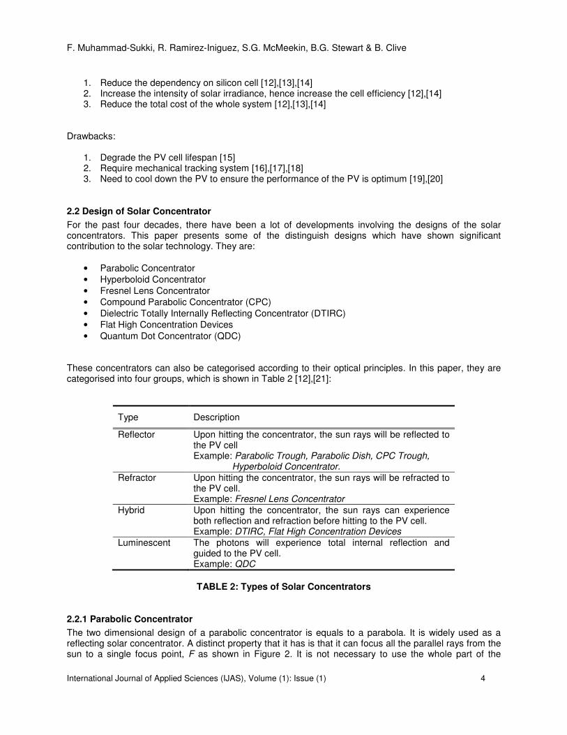
1. Reduce the dependency on silicon cell [12],[13],[14] 2. Increase the intensity of solar irradiance, hence increase the cell efficiency [12],[14] 3. Reduce the total cost of the whole system [12],[13],[14]
Drawbacks:
1. Degrade the PV cell lifespan [15] 2. Require mechanical tracking system [16],[17],[18] 3. Need to cool down the PV to ensure the performance of the PV is optimum [19],[20]
2.2 Design of Solar Concentrator
For the past four decades, there have been a lot of developments involving the designs of the solar concentrators. This paper presents some of the distinguish designs which have shown significant contribution to the solar technology. They are:
• Parabolic Concentrator
• Hyperboloid Concentrator
• Fresnel Lens Concentrator
• Compound Parabolic Concentrator (CPC)
• Dielectric Totally Internally Reflecting Concentrator (DTIRC)
• Flat High Concentration Devices
• Quantum Dot Concentrator (QDC)
These concentrators can also be categorised according to their optical principles. In this paper, they are categorised into four groups, which is shown in Table 2 [12],[21]:
Type Description
Reflector Upon hitting the concentrator, the sun rays will be reflected to the PV cell Example: Parabolic Trough, Parabolic Dish, CPC Trough, Hyperboloid Concentrator.
Refractor Upon hitting the concentrator, the sun rays will be refracted to the PV cell. Example: Fresnel Lens Concentrator
Hybrid Upon hitting the concentrator, the sun rays can experience both reflection and refraction before hitting to the PV cell. Example: DTIRC, Flat High Concentration Devices
Luminescent The photons will experience total internal reflection and guided to the PV cell. Example: QDC
TABLE 2: Types of Solar Concentrators
2.2.1 Parabolic Concentrator
The two dimensional design of a parabolic concentrator is equals to a parabola. It is widely used as a reflecting solar concentrator. A distinct property that it has is that it can focus all the parallel rays from the sun to a single focus point, F as shown in Figure 2. It is not necessary to use the whole part of the

F. Muhammad-Sukki, R. Ramirez-Iniguez, S.G. McMeekin, B.G. Stewart & B. Clive
International Journal of Applied Sciences (IJAS), Volume (1): Issue (1) 5
parabola curve to construct the concentrator. Most of the parabolic concentrator employs only a truncated portion of the parabola. Currently, there are two available designs of parabolic concentrator. One is by rotating the two dimensional design along the x-axis to produce a parabolic dish, and the other way is by having a parabolic trough. Both of the designs act as reflectors and are used mostly in concentrating solar power system in big solar power plant [22]. The EUCLIDES-THERMIE Plant in Tenerife, Canary Island employs the parabolic trough concentrators in the 480kW concentrator project [12],[23]. Although this concentrator could provide a high concentration, it requires larger field of view to maximise the sun energy collection. To obtain maximum efficiency, it needs a good tracking system, which is quite expensive. That is why this type of concentrator is not preferred in a small residential house.
FIGURE 2: The sun rays are focused at the focal point of the parabola [22]
2.2.2 Hyperboloid Concentrator
The general design of a hyperboloid concentrator is shown in Figure 3. It consists of two hyperbolic sections, AB and A’B’. The hyperboloid concentrator can be produces by rotating the two dimensional design along its symmetrical axis. The diameters of the entrance and exit aperture are labeled as d1 and d2 respectively. If the inside wall of the hyperbolic profile is considered as a mirror, the sun rays entering the concentrator from AA’ will be reflected and focused to the exit aperture BB’. The advantage of this concentrator is that it is very compact, since only truncated version of the concentrator needs to be used. Because of this factor, it is mainly used as a secondary concentrator. An example of application of this concentrator has been developed by SolFocus, with the intention of reducing the cost of solar electricity. The design with Cassegranian-like architecture managed to produce 250W peak in a single Generation 1 solar panel [25]. However, in most applications, it requires the usage of lenses at the entrance diameter AA’ in order for the concentrator to work effectively [24].

F. Muhammad-Sukki, R. Ramirez-Iniguez, S.G. McMeekin, B.G. Stewart & B. Clive
International Journal of Applied Sciences (IJAS), Volume (1): Issue (1) 6
FIGURE 3: Hyperboloid Concentrator [24]
2.2.3 Fresnel Concentrator
Fresnel lens function is similar to the conventional lens, by refracting the rays and focusing them at one focal point. It generally has two sections; a flat upper surface and a back surface that employs canted facets. The facet is an approximation of the curvature of a lens (see Figure 4). A good linear Fresnel lens could employ around 100 facets per millimeter [22]. There are two ways to use this concentrator; a point focus Fresnel lens or a line focus Fresnel lens. An application of this concentrator can be seen in the Sacramento Municipal Utility District, where the Fresnel lenses are used in the 30kW utility grid-connected plant [12]. The advantage of a Fresnel lens over a conventional lens is that it is thinner and requires a lesser amount of material to fabricate [21]. It also has the capability to separate the direct and diffuse light, making it suitable to control the illumination and temperature of a building interior [26]. One of the disadvantages of this concentrator will be due to the sharpness of the facet. An error in the manufacturing process could create a rounder shape at the edges of the facets, causing the rays improperly focused at the receiver [22].
FIGURE 4: Fresnel Lenses [22]
F. Muhammad-Sukki, R. Ramirez-Iniguez, S.G. McMeekin, B.G. Stewart & B. Clive
International Journal of Applied Sciences (IJAS), Volume (1): Issue (1) 7
2.2.4 Compound Parabolic Concentrator (CPC)
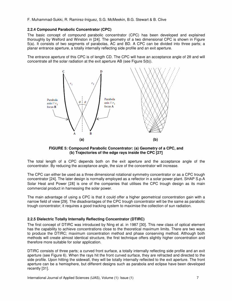
The basic concept of compound parabolic concentrator (CPC) has been developed and explained thoroughly by Welford and Winston in [24]. The geometry of a two dimensional CPC is shown in Figure 5(a). It consists of two segments of parabolas, AC and BD. A CPC can be divided into three parts; a planar entrance aperture, a totally internally reflecting side profile and an exit aperture. The entrance aperture of this CPC is of length CD. The CPC will have an acceptance angle of 2θ and will concentrate all the solar radiation at the exit aperture AB (see Figure 5(b)).
(a) (b)
FIGURE 5: Compound Parabolic Concentrator: (a) Geometry of a CPC, and (b) Trajectories of the edge rays inside the CPC [27]
The total length of a CPC depends both on the exit aperture and the acceptance angle of the concentrator. By reducing the acceptance angle, the size of the concentrator will increase. The CPC can either be used as a three dimensional rotational symmetry concentrator or as a CPC trough concentrator [24]. The later design is normally employed as a reflector in a solar power plant. SHAP S.p.A
Solar Heat and Power [28] is one of the companies that utilises the CPC trough design as its main
commercial product in harnessing the solar power. The main advantage of using a CPC is that it could offer a higher geometrical concentration gain with a narrow field of view [29]. The disadvantages of the CPC trough concentrator will be the same as parabolic trough concentrator; it requires a good tracking system to maximise the collection of sun radiation.
2.2.5 Dielectric Totally Internally Reflecting Concentrator (DTIRC)
The first concept of DTIRC was introduced by Ning et al. in 1987 [30]. This new class of optical element has the capability to achieve concentrations close to the theoretical maximum limits. There are two ways to produce the DTIRC; maximum concentration method and phase conserving method. Although both methods will create almost identical structure, the first technique offers slightly higher concentration and therefore more suitable for solar application. DTIRC consists of three parts; a curved front surface, a totally internally reflecting side profile and an exit aperture (see Figure 6). When the rays hit the front curved surface, they are refracted and directed to the side profile. Upon hitting the sidewall, they will be totally internally reflected to the exit aperture. The front aperture can be a hemisphere, but different designs such as parabola and eclipse have been developed recently [31].
F. Muhammad-Sukki, R. Ramirez-Iniguez, S.G. McMeekin, B.G. Stewart & B. Clive
International Journal of Applied Sciences (IJAS), Volume (1): Issue (1) 8
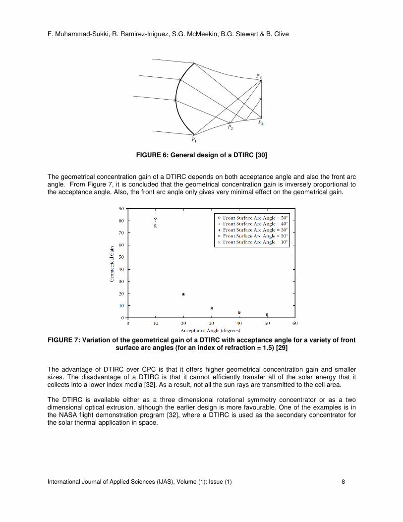
FIGURE 6: General design of a DTIRC [30]
The geometrical concentration gain of a DTIRC depends on both acceptance angle and also the front arc angle. From Figure 7, it is concluded that the geometrical concentration gain is inversely proportional to the acceptance angle. Also, the front arc angle only gives very minimal effect on the geometrical gain.
FIGURE 7: Variation of the geometrical gain of a DTIRC with acceptance angle for a variety of front
surface arc angles (for an index of refraction = 1.5) [29]
The advantage of DTIRC over CPC is that it offers higher geometrical concentration gain and smaller sizes. The disadvantage of a DTIRC is that it cannot efficiently transfer all of the solar energy that it collects into a lower index media [32]. As a result, not all the sun rays are transmitted to the cell area. The DTIRC is available either as a three dimensional rotational symmetry concentrator or as a two dimensional optical extrusion, although the earlier design is more favourable. One of the examples is in the NASA flight demonstration program [32], where a DTIRC is used as the secondary concentrator for the solar thermal application in space.

F. Muhammad-Sukki, R. Ramirez-Iniguez, S.G. McMeekin, B.G. Stewart & B. Clive
International Journal of Applied Sciences (IJAS), Volume (1): Issue (1) 9
2.2.6 Flat High Concentration Devices
Instituto de Energia Solar, Universidad Politecnica de Madrid (UPM) in Spain, Minano and Benitez in
particular, have successfully produced a different class of nonimaging concentrators. The concentrators are able to achieve theoretical maximum acceptance-angle-concentration. Currently, Light Prescription Innovators (LPI) is working closely with UPM to further develop and market these concentrators [12],[33]. Since 1995, there are five available designs; RR, XX, XR, RX and RXI [2],[34],[35],[36]. In this design, ‘R’ represents refraction, ‘X’ denotes reflection and ‘I’ means total internal reflection. Basically, an XR concentrator means that the rays in this concentrator will first experience a reflection followed by refraction, before reaching the receiver of which a PV cell is attached [34]. For simplicity, we will restrict the discussion on the RXI design. Figure 8 shows a typical diagram of an RXI concentrator. It is devised using the Simultaneous Multiple Surface, also known as the Minano-Benitez design method [27]. An RXI concentrator has three sections; an upper surface with a mirror at the centre, a lower surface made from mirror, and a receiver. Minano et. al. [36] has shown that by using an RXI with rotational symmetry and the refractive index of the dielectric is 1.5, a concentrator with an acceptance angle of +2.7
0 could achieve a concentration
factor of 1000x. These concentrators have two major benefits; they are very compact and offer very high concentration. However, there are some disadvantages of this design. Due to the cell’s position, it is difficult to create electrical connection and heat sinking. The cell dimension must be designed to be as minimal as possible to reduce shadowing effect [16].
FIGURE 8: Flat high concentrator device - RXI Concentrator [36]
2.2.7 Quantum Dot Concentrator (QDC)
Quantum dot concentrator, (QDC) is a planar device that consists of three parts; a transparent sheet of glass or plastic made doped with quantum dots (QDs), reflective mirrors mounted on the three edges and back surface, and an exit where a PV cell is attached (see Figure 9) [37].
When the sun radiation hits the surface of a QDC, a part of the radiation will be refracted by the fluorescent material and absorbed by the QDs. Photons are then reemitted in all direction and are guided to the PV cell via total internal reflection. The total geometrical concentration will be the ratio of the large surface area of glass to the area of PV cell. QDC major advantage is that it does not requires any tracking as other conventional concentrator. It can also make full use of both direct and diffuse solar radiation [38]. However, the drawback of the QDC is that the development of QDC is restricted to high requirements on the luminescent dyes; i.e. high quantum efficiency, suitable absorption spectra and redshifts, and stability under illumination [[39]].

F. Muhammad-Sukki, R. Ramirez-Iniguez, S.G. McMeekin, B.G. Stewart & B. Clive
International Journal of Applied Sciences (IJAS), Volume (1): Issue (1) 10
Evident Technologies [40] is one of the companies that sees the huge potential in this concentrator and has been marketing the quantum dot products to the consumers.
FIGURE 9: Principal of Quantum Dot Concentrator (QDC) [37]
To summarize the various design of the concentrator, Table 2 shows the comparison of each concentrator, showing the advantage and disadvantage of each design respectively.
Type of Concentrator Advantage Disadvantage
Parabolic Concentrator • High concentration. • Requires larger field of view.
• Need a good tracking system.
Hyperboloid Concentrator
• Compact • Need to introduce lens at the entrance aperture to work effectively.
Fresnel Concentrator • Thinner than conventional lens.
• Requires less material than conventional lens.
• Able to separate the direct and diffuse light - suitable to control the illumination and temperature of a building interior.
• Imperfection on the edges of the facets, causing the rays improperly focused at the receiver.
Compound Parabolic Concentrator
• Higher gain when its field of view is narrow.
• Need a good tracking system.
Dielectric Totally Internally Reflecting Concentrator
• Higher gain than CPC.
• Smaller sizes than CPC.
• Cannot efficiently transfer all of the solar energy that it collects into a lower index media.
Flat High Concentration Devices (RR, XX, XR, RX, and RXI)
• Compact.
• Very high concentration
• Difficulty to create electrical connection and heat sinking due to the position of the cell.
• The cell dimension must be designed to a minimum to reduce shadowing effect.
Quantum Dot Concentrator
• No tracking needed.
• Fully utilise both direct and diffuse solar radiation
• Restricted in terms of development due to the requirements on the luminescent dyes.
TABLE 2: Summary of the Advantage and Disadvantage of the Concentrators

F. Muhammad-Sukki, R. Ramirez-Iniguez, S.G. McMeekin, B.G. Stewart & B. Clive
International Journal of Applied Sciences (IJAS), Volume (1): Issue (1) 11
2.3 Performance of Solar Concentrator
There are numerous projects regarding the implementation of the solar concentrators. These projects
have been done by research centres, universities and companies to investigate and analyse the reliability
and the performance of the concentrator. Table 3 shows some of the projects which have been
conducted throughout the world, showing the principal investigator’s name and the location of the project.
It presents the estimated output obtained as well as the overall efficiency of the system.
Name Location Concentrator
type
Focus (Point/Linear)
Output (kW)
Sun concentration
(X)2
Tracking (yes/no)
Efficiency of the
system Ref
Alpha Solarco, Pahrump, Nevada,
USA fresnel lens point 15 n/a yes n/a
[41] [42]
AMONIX and Arizona Public
Service
Arizona, USA
fresnel lens point 300 250 yes 24.0% [43]
Australian National
University
Spring Valley,
Australia
parabolic trough
linear n/a 30 yes 15.0% [44]
PETAL Sede Boqer,
Israel parabolic
dishes point 154000 400 yes 16.5% [45]
BP Solar and the Polytechnical University of
Madrid
Tenerife, Canary
Island, USA
parabolic trough
linear 480 38 yes 13.0% [23] [46]
Entech Inc Ft. Davis,
Texas, USA fresnel lenses linear 100 20 yes 15.0% [47]
Fraunhofer-Institute for Solar Energy Systems
Freiburgh, Germany
parabolic trough and
CPC3
linear and point
n/a 214 yes 77.5% [48]
Polytechnical University of
Madrid
Madrid, Spain
flat concentration devices (RXI)
point n/a 1000 no n/a [49]
Photovoltaics International, LLC
SacramentoCalifornia,
USA fresnel lens linear 30 10 yes 12.7%
[12] [50]
Solar Research Corporation,
Pty. Ltd. Australia parabolic dish point 0.2 239 yes 22.0% [51]
SolFocus Ben Gurien University,
Israel
paraboloid and hyperboloid
4
point and point
0.25 500 yes 81% [25]
SunPower Corporation
USA fresnel lens point n/a 250 - 400 n/a 27.0% [10]
TABLE 3: Worldwide projects related to solar concentrators. Adapted from [10]
From the table, it is evident that the solar concentrator has the capabilities to increase the efficiency of the
system by concentrating the sun rays from a large area into a smaller area, hence reducing the usage of
2 One sun concentration, 1X = 1000W/m
2
3 This is a two-stage concentration process. The first stage uses the parabolic trough and the second stage is using the CPC. The
focal point of the concentrator is line and point focus respectively. 4 This is a two-stage concentration process. The first stage uses the paraboloid concentrator and the second stage is using the
hyperboloid concentrator. The focal point of each concentrator is point focus.

F. Muhammad-Sukki, R. Ramirez-Iniguez, S.G. McMeekin, B.G. Stewart & B. Clive
International Journal of Applied Sciences (IJAS), Volume (1): Issue (1) 12
silicon cell. The reduction in silicon cell will lower the cost of the solar cell. It is then possible to say that
the concentrators are capable of lowering the cost of the system, hence delivering a competitive energy
market to the consumers.
3. CONCLUSION & FUTURE WORK
The main conclusions of this paper are summarised hereunder.
1. Solar energy has vast potential, but its contribution to the world’s energy market is still very limited.
2. Solar concentrators could bring down the total cost of the solar cell, thus making the solar technology cheaper and affordable, but at the same time does not compromise the overall performance of the solar technology.
3. There are a lot of designs of solar concentrators. Each design has its own advantages and disadvantages.
4. In spite of the advance designs achieved so far, there are still a lot of improvements that can be done especially on the concentrator designs [52].
Future Work The team is currently working on optimizing the solar concentrator in the SolarBrane [13], a BIPV system developed by SolarEmpower Ltd.
Acknowledgment The authors would like to acknowledge the collaboration of SolarEmpower Ltd. for its contribution to this project.
4. REFERENCES
[1]. REN21, “Renewables Global Status Report: 2009 Update”, Renewable Energy Policy Network for the 21
st Century (REN21), 2009: Available at
http://www.ren21.net/pdf/RE_GSR_2009_Update.pdf (access on the 02/02/2010).
[2]. R. Winston, J.C. Minano and P. Benitez, “Nonimaging Optics”, Elsevier Academic Press, pp. 1-217, (2005).
[3]. D. Abbott, “Keeping the Energy Debate Clean: How Do We Supply the World’s Energy Needs?”. In Proceedings of the IEEE, 98(1): 42-66, 2009.
[4]. Q. Liu, G. Yu, and J.J. Liu, “Solar Radiation as Large-Scale Resource for Energy-Short World”, Energy & Environment, 20(3): 319-329, 2009.
[5]. N.J. Ekins-Daukes, “Solar Energy for Heat and Electricity: The Potential for Mitigating Climate Change”, Briefing Paper No 1: 1-12, 2009.
[6]. REN21, “REN21 Renewables 2007 Global Status Report”, Renewable Energy Policy Network for the 21
st Century (REN21), 2007: Available at http://www.ren21.net/pdf/RE2007_Slides.pdf
(access on the 09/03/2010). [7]. F. Jiang and A. Wong, "Study on the Performance of Different Types of PV Modules in
Singapore". In Proceedings of International Power Engineering Conference (IPEC 2005), Singapore, 2005.
[8]. F. Kamel Abdalla and P. Wilson, “Cost of kWh Produced and Payback Time of a PV-Solar-Thermal-Combined Rooftop Collector at Different Locations in New Zealand”. In EEA Annual

F. Muhammad-Sukki, R. Ramirez-Iniguez, S.G. McMeekin, B.G. Stewart & B. Clive
International Journal of Applied Sciences (IJAS), Volume (1): Issue (1) 13
Conference & Trade Exhibition 2002: Meeting the Challenges of Growth, Christchurch, New Zealand, 2002.
[9]. W. Guter, J. Schöne, S.P. Philipps, M. Steiner, G. Siefer, A. Wekkeli, E. Welser, E. Oliva, A.W. Bett, and Frank Dimroth, “Current-Matched Triple-Junction Solar Cell Reaching 41.1% Conversion Efficiency Under Concentrated Sunlight”, Applied Physics Letter, 94, 22, 2009.
[10]. R.M, Swanson, “The Promise of Concentrators”, Progress in Photovoltaics: Research and Applications, 8: 93-111, 2000.
[11]. C.F. Chen, C.H. Lin, H.T.Jan & Y.L. Yang, “ Design of a Solar Concentrator Combining Paraboloidal and Hyperbolic Mirrors Using Ray Tracing Method”, Optics Communication, 282: 360-366, 2009.
[12]. G. Sala, D. Pachón and I. Antón, “Book 1: Classification of PV Concentrators”, Test, Rating, and Specification of PV Concentrator Components and Systems, C – Rating Project, (2000). Available at http://www.ies-def.upm.es/ies/CRATING/crating.htm (access on the 03/05/2010).
[13]. SolarEmpower Ltd. Available at http://www.solarempower.com/ (access on the 02/01/2010).
[14]. J.C. Miñano and P. Benítez, “High Concentration Photovoltaics: Potentials and Challenges“. Webinar in Photovoltaic Concentration, USA, 2008.
[15]. A. R. Mahoney, J.E. Cannon and J.R. Woodworth, “Accelerated UV-aging of Acrylic Materials used in PV Concentrator Systems”. In Proceedings in the 2 3rd IEEE Photovoltaic Specialists Conference, Louisville, Kentucky, USA, 1993.
[16]. A. Terao, W.P. Mulligan, S.G. Daroczi, O.C. Pujol, P.J. Verlinden and R.M. Swanson “A Mirror-Less Design for Micro-Concentrator Module”. In Proceedings of the 28
th IEEE Photovoltaic
Specialists Conference, Anchorage, Alaska. 2000.
[17]. A.J. Chatten, K.W.J. Barnham, B.F. Buxton, N.J. Ekins-Daukes3 and M. A. Malik, “Quantum Dot Solar Concentrator”. In Proceedings of Symposium on the Efficient Use of Solar Radiation in Photovoltaics Power Engineering, St. Petersburg, USA, 2003.
[18]. J.A. Manrique, “A Compound Parabolic Concentrator”, International Communications in Heat and Mass Transfer, 11: 267-273, 1984.
[19]. T. Nordmann and L.Clavadetscher, “Understanding Temperature Effects on PV System Performance”. In Proceedings of the 3rd World Conference on Photovoltaic Energy Conversion, Osaka, Japan, 2003.
[20]. V.B. Omubo-Pepple, C. Israel-Cookey and G.I. Alaminokuma, “ Effects of Temperature, Solar Flux and Relative Humidity on the Efficient Conversion of Solar Energy to Electricity”, European Journal of Scientific Research, 35(2): 173-180, 2009.
[21]. G.M. Kaplan, “Understanding Solar Concentrators”, Technical Paper # 30, Volunteers in Technical Assistance (VITA), 1985.
[22]. W.B. Stine and M. Geyer, “Power from the Sun”. Available at http://www.powerfromthesun.net/index.htm (access on the 05/02/2010).
[23]. G. Sala, J.C. Arboiro, A. Luque, I. Antón, M.P. Gasson, N.B. Mason, K.C. Heasman, T.M. Bruton, E. Mera, E. Camblor, P. Datta, M. Cendagorta, M.P. Friend, P. Valera, S. González, F. Dobón and F. Pérez, “480 kWpeak EUCLIDES Concentrator Power Plant using Parabolic Troughs". In Proceedings of the 2nd World Conference on PV Solar Energy Conversion, Vienna, 1998.

F. Muhammad-Sukki, R. Ramirez-Iniguez, S.G. McMeekin, B.G. Stewart & B. Clive
International Journal of Applied Sciences (IJAS), Volume (1): Issue (1) 14
[24]. W.T. Welford and R. Winston, “High Collection Nonimaging Optics”, Academic Press Inc., pp. 53-
273 (1989).
[25]. S. Horne, G. Conley, J. Gordon, D. Fork, P. Meada, E. Schrader and T. Zimmermann, “A Solid 500 Sun Compound Concentrator PV Design”. In Proceedings of the IEEE 4th World Conference on Photovoltaic Energy Conversion, Waikoloa, Hawaii, 2006.
[26]. Y. Tripanagnostopoulos, C. Siabekou and J.K. Tonui,” The Fresnel Lens Concept for Solar Control of Buildings”, Solar Energy, 81: 661-675, 2007.
[27]. J.C. Chaves, “Introduction to Nonimaging Optics”, Taylor and Francis Group LLC., pp.12-324 (2008).
[28]. SHAP S.p.A Solar Heat and Power. Available at http://www.shap.it/ENG/default.htm (access on the 04/05/2010)
[29]. R. Ramirez-Iniguez, S.M. Idrus and Z. Sun, “Optical Wireless Communications: IR for Wireless Connectivity”, Taylor and Francis Group LLC., pp.73-139 (2008).
[30]. X. Ning, R. Winston and J. O’Gallagher, “Dielectric Totally Internally Reflecting Concentrators”, Applied Optics, 26(2): 300–305, 1987.
[31]. R. Ramirez-Iniguez and R.J. Green, “Optical Antenna Design for Indoor Optical Wireless Communication Systems”, International Journal of Communication Systems, 18: 229-245, 2005.
[32]. M. F. Piszczor and R.P. Macosko, “A High-Efficiency Refractive Secondary Solar Concentrator for High Temperature Solar Thermal Applications”, NASA Technical Memorandum, NASA/TM-2000-208401. 2000.
[33]. Light Prescription Innovators (LPI). Available at http://www.lpi-llc.com/index.php (access on
the 04/05/2010)
[34]. J.C. Minano, J.C. Gonzalez and P. Benitez, “High-gain, Compact, Nonimaging Concentrator: RXI”, Applied Optics, 34(34):7850-7856, 1995.
[35]. J.C. Minano, P. Benitez and J.C. Gonzalez, “RX: A Nonimaging Concentrator”, Applied Optics, 34(13):2226-2235, 1995.
[36]. J.C. Minano, J.C. Gonzales and I. Zanesco, “Flat High Concentration Devices”. In Proceeding of 1
st World Conference on Photovoltaic Energy Conversion, Hawaii. 1994.
[37]. S.J. Gallagher, B. Norton and P.C. Eames, “Quantum Dot Solar Concentrators: Electrical
Conversion Efficiencies and Comparative Concentrating Factors of Fabricated Devices”, Solar Energy, 81: 813-821, 2007.
[38]. A. J. Chatten, K. W. J. Barnham, B. F. Buxton, N. J. Ekins-Daukes and M. A. Malik, “Quantum Dot Solar Concentrators and Modules”. In Proceedings of 19th European Photovoltaic Solar Energy Conference, Paris. 2004.
[39]. A. Goetzberger, W. Stahl and V. Witter, “Physical Limitation of the Concentration of Direct and Diffuse Radiation”. In Proceedings of the 6
th European Photovoltaic Solar Energy Conference,
Reidel, Dordrecht. 1985.
[40]. Evident Technologies. Available at http://www.evidenttech.com/ (access on the 04/05/2010)

F. Muhammad-Sukki, R. Ramirez-Iniguez, S.G. McMeekin, B.G. Stewart & B. Clive
International Journal of Applied Sciences (IJAS), Volume (1): Issue (1) 15
[41]. D. Carroll, B. Bailor and E. Schmidt , "Update on Alpha Solarco's Concentrator Array Program" In Proceeding of 22
nd IEEE Photovoltaic Specialists Conference, Las Vegas, NV. 1991.
[42]. D. Anderson, B. Bailor, D. Carroll, E. Schmidt, P. Tyjewski and M. Uroshevich, “Alpha Solarco’s
Photovoltaic Concentrator Development Program”, Contractor Report SAND95-155. 1995
[43]. H. Hayden, P. Johnston, V. Garboushian and D. Roubideaux, “APS Installation and Operation of 300 kW of Amonix High Concentration PV systems," In Proceeding of 29
th Photovoltaic
Specialists Conference, New Orleans, Louisiana. 2002.
[44]. A. W. Blakers and J. Smeltink, “The ANU PV/Trough Concentrator System”, In Proceeding of 2nd
World Conference on Photovoltaic Solar Energy Conversion, Vienna, Austria. 1998.
[45]. D. Faiman, S. Biryukov and K. K. Pearlmutter, “PETAL: A Research Pathway to Fossil-Competitive Solar Electricity”, In Proceeding of 29
th Photovoltaic Specialists Conference, New
Orleans, Louisiana. 2002.
[46]. G. Sala, I. Antón, J.C. Arboiro, A. Luque, E. Cmblop, E. Mera, M. Gasson, M. Cendagorta, P. Valera, M.P. Friend, J. Monedero, S.Gonzalez, F. Dobon and I. Luque, “The 480 kWp EUCLIDES™-Thermie Power Plant: Installation, Set-Up and First Results”, In Proceeding of 16th European Photovoltaic Solar Energy Conference, Glasgow, UK. 2000.
[47]. M.J. O'Neill and A.J. McDanal, "Fourth-Generation Concentrator System: From the Lab to the Factory to the Field," In Proceeding of First World Conference on Photovoltaic Energy Conversion, Hawaii. 1994.
[48]. M. Brunotte, A. Goetzberger and U. Blieske, “Two-Stage Concentrator Permitting Concentration Factors up to 300x with One-Axis Tracking”, Solar Energy, 56(3):285-300, 1996.
[49]. J. L. Alvarez, M. Hernandez, P. Benitez and J. C. Minano, “Experimental Measurements of RXI Concentrators for Photovoltaic Applications”, In Proceeding of 2nd World Conference and Exhibition on Photovoltaic Solar Energy Conversion, Vienna. 1998.
[50]. N. Kaminar, J. McEntee, P. Stark and D. Curchod, “SEA 10 _ Concentrator Development Progress”, In Proceeding of 22nd IEEE Photovoltaic Specialists Conference, Las Vegas. 1991.
[51]. J. B. Lasich, A. Cleeve, N. Kaila, G. Ganakas, M. Timmons, R. Venkatasubramanian, T. Colpitts and J. Hills, ”Close-packed Cell Arrays for Dish Concentrators”, In Proceeding of 1st World Conference on Photovoltaic Energy Conversion, Hawaii, 1994.
[52]. D. Infield, “A Road Map for Photovoltaics Research in the UK”, UK Energy Research Centre (UKERC) Research Report, REF UKERC/RR/FSE/2007/001. 2007. Available at
http://ukerc.rl.ac.uk/ERR0301.html (access on the 03/05/2010).


![Ericsson heat engine with microchannel recuperator for solar … · for solar concentrator with flat mirrors, ... There are solar concentrators of different types [2]. ... a heat](https://static.fdocuments.us/doc/165x107/5acf77527f8b9ae2138c8ba7/ericsson-heat-engine-with-microchannel-recuperator-for-solar-solar-concentrator.jpg)


