Soil - Structure Interaction of Multistorey R.C.C....
12
Vol-4 Issue-2 2018 IJARIIE-ISSN(O)-2395-4396 7798 www.ijariie.com 1417 Soil - Structure Interaction of Multistorey R.C.C. Frames ALESH MATALE , PROF. AMEY KHEDIKAR Nagpur, India Abstract Comprehensive experimental and analytical studies have been carried out to understand the behavior of existing frame buildings constructed before the introduction of seismic design codes in 1970’s.Different aspects of the response have been investigated and inherent weaknesses have been pointedout.This usually has been done assuming a fixed-base structure while ignoring the flexibility of soil andfoundation.In this thesis, the interaction between the super-structure and sub-structure (SSI) is investigated by modelling the soil as simple as possible to capture the overall response of the system.As new analytical hysteresis rules and more advanced tools of analysis have been developed in recentyears, the linear response of a structure which can be representative of a broad range of existing or newly designed structures, is investigated while allowingfor flexibility of the soil-foundation system and SSI effects. The use of flexible base in the analysis can lead toreduction in the structural response and damage consequences in joints and infills. The results of this study suggest that the compliance of simply modelled soilfor typical building structures have in average beneficial effects in terms of structural demand especially for stiff structures. Keywords :-Soil structure interaction, Linear analysis, Shear wall, Soft soil. Introduction A common design practice for dynamic loading assumes the building to be fixed at their bases. In reality the supporting soil medium allows movement to some extent due to its property to deform. This may decrease the overall stiffness of the structural system and hence may increase the natural periods of the system, such influence of partial fixity of structures at foundation level due to soil flexibility intern alters the response. On the other hand, the extent of fixity offered by soil at the base of the structure depends on the load transferred from the structure to the soil as the same decides the type and size of foundation to be provided. Such an interdependent behavior of soil and structure regulating the overall response is referred to as soil structure interaction. This effect of soil flexibility is to be accounted through consideration of springs of specified stiffness. Thus the change in natural period due to effect of soil structure interaction may be an important issue from the viewpoint of design considerations. Also it is usual practice to treat the brick infill as a non-structural element and therefore all the lateral loads are assumed to be resisted by the frame, but performance of buildings in the recent earthquakes (e g: 1985 Mexico City earthquake, 2001 Bhuj earthquake) clearly illustrates that the presence of infill wall has significant structural implication. Therefore, the structural contribution of infill wall cannot simply be neglected particularly in regions of moderate and high seismicity where the frame infill interaction may cause substantial increase in both stiffness and strength. A review of analysis and design provisions related to masonry infill RC frames in seismic design codes of different countries show that only a few codes have considered the effect of infill in analysis and design of masonry in filled RC frames. On the other hand, the stiffness and strength of in filled frames with openings are not taken care of by most of the codes. Hence the behavior of in filled frames with opening needs to be studied extensively in order to develop a rational approach or guidelines for design. In the last three decades, the effect of SSI on earthquake response of structures has attracted an intensive interest among researchers and engineers. Most of these researches focus on theoretical analysis, while less has been done on the experimental study. The interaction among the structure, foundation and soil medium below the foundation alter the actual behaviour of the structure considerably as obtained by the consideration of the structure alone. Flexibility of soil medium below foundation decreases the overall stiffness of the building frames resulting in an increase in the natural period of the system.
Transcript of Soil - Structure Interaction of Multistorey R.C.C....

Vol-4 Issue-2 2018 IJARIIE-ISSN(O)-2395-4396
7798 www.ijariie.com 1417
Soil - Structure Interaction of Multistorey
R.C.C. Frames
ALESH MATALE , PROF. AMEY KHEDIKAR
Nagpur, India
Abstract
Comprehensive experimental and analytical studies have been carried out to understand the behavior of existing
frame buildings constructed before the introduction of seismic design codes in 1970’s.Different aspects of the
response have been investigated and inherent weaknesses have been pointedout.This usually has been done
assuming a fixed-base structure while ignoring the flexibility of soil andfoundation.In this thesis, the interaction
between the super-structure and sub-structure (SSI) is investigated by modelling the soil as simple as possible to
capture the overall response of the system.As new analytical hysteresis rules and more advanced tools of analysis
have been developed in recentyears, the linear response of a structure which can be representative of a broad range
of existing or newly designed structures, is investigated while allowingfor flexibility of the soil-foundation system
and SSI effects. The use of flexible base in the analysis can lead toreduction in the structural response and damage
consequences in joints and infills.
The results of this study suggest that the compliance of simply modelled soilfor typical building structures have in
average beneficial effects in terms of structural demand especially for stiff structures.
Keywords :-Soil structure interaction, Linear analysis, Shear wall, Soft soil.
Introduction
A common design practice for dynamic loading assumes the building to be fixed at their bases. In reality the
supporting soil medium allows movement to some extent due to its property to deform. This may decrease the
overall stiffness of the structural system and hence may increase the natural periods of the system, such influence of
partial fixity of structures at foundation level due to soil flexibility intern alters the response. On the other hand, the
extent of fixity offered by soil at the base of the structure depends on the load transferred from the structure to the
soil as the same decides the type and size of foundation to be provided. Such an interdependent behavior of soil and
structure regulating the overall response is referred to as soil structure interaction.
This effect of soil flexibility is to be accounted through consideration of springs of specified stiffness. Thus the
change in natural period due to effect of soil structure interaction may be an important issue from the viewpoint of
design considerations. Also it is usual practice to treat the brick infill as a non-structural element and therefore all
the lateral loads are assumed to be resisted by the frame, but performance of buildings in the recent earthquakes (e g:
1985 Mexico City earthquake, 2001 Bhuj earthquake) clearly illustrates that the presence of infill wall has
significant structural implication. Therefore, the structural contribution of infill wall cannot simply be neglected
particularly in regions of moderate and high seismicity where the frame infill interaction may cause substantial
increase in both stiffness and strength. A review of analysis and design provisions related to masonry infill RC
frames in seismic design codes of different countries show that only a few codes have considered the effect of infill
in analysis and design of masonry in filled RC frames. On the other hand, the stiffness and strength of in filled
frames with openings are not taken care of by most of the codes. Hence the behavior of in filled frames with opening
needs to be studied extensively in order to develop a rational approach or guidelines for design.
In the last three decades, the effect of SSI on earthquake response of structures has attracted an intensive interest
among researchers and engineers. Most of these researches focus on theoretical analysis, while less has been done
on the experimental study. The interaction among the structure, foundation and soil medium below the foundation
alter the actual behaviour of the structure considerably as obtained by the consideration of the structure alone.
Flexibility of soil medium below foundation decreases the overall stiffness of the building frames resulting in an
increase in the natural period of the system.

Vol-4 Issue-2 2018 IJARIIE-ISSN(O)-2395-4396
7798 www.ijariie.com 1418
Review of Literature
Badry, P. and Satyam, N. (2016) Seismic damage surveys and analyses conducted on modes of failure of structures
during past earthquakes observed that the asymmetrical buildings show the most vulnerable effect throughout the
course of failures.
Lu Y., et al. (2016)a comprehensive parametric study has been carried out to investigate the seismic performance of
multistory shear buildings considering soil–structure interaction (SSI). More than 40,000 SDOF and MDOFmodels
are designed based on different lateral seismic load patterns and target ductility demands to representa wide range of
building structures constructed on shallow foundations.
Mitropoulou C. C., et al. (2016)3D reinforced concrete (RC) and steel building structures have been considered for
studying the effectof soil–structure interaction modelling on the structural fragility assessment of such structures.
Shanmugam et al. (2015) the effect of soil-structure interaction on a four storeyed, two bay frame resting on pile
and embedded in the cohesive soil was examined.
Li et al. (2014)Taking the Shanghai Tower with a total height of 632 m as the research object, thesubstructure
approach is used to simulate the SSI effect on the seismic responses of Shanghai Tower.
Mathematical Modelling
Idealization of Structure
To study the dynamic behavior of building structure while considering the effect of soil structure interaction,
building frame is modeled as 3D space frame using standard two nodded frame element with two longitudinal
degrees of freedom and one rotational degree of freedom at each node. At the interface of infill and frame, the infill
element and the frame element are given same nodes.
The idealized form of a typical 3 bay x 3 bay 10 storey building frame with infill wall modeled as represented
schematically in figure the present study also considers bare frame to see how correctly the influence of soil
structure interaction on dynamic behavior can be predicted. This may give an idea about the error, which one should
liable to commit if this popular but grossly inaccurate approach is invoked.
A 3 bay x 3 bay building frames with 10 storey’s on isolated footing have been considered. The height of each
storey is taken as 3.6 m and the longitudinal and transverse dimensions of 3 bays x 3 bay building is taken as 6 m for
central bay and 6 m for the two side bays. For all the buildings the dimensions of reinforced concrete column are
taken as 600 x 600 mm and for beam it is 200 x 600 mm. Similarly thickness for roof and floor is taken as 150 mm
and their corresponding dead load is directly applied on the beam. The brick infill with thickness 150 mm. All the
above dimensions were arrived on the basis of the design following the respective Indian code for design of
reinforced concrete structure .However, these design data are believed to be practicable and hence, do not affect the
generality of the conclusion.

Vol-4 Issue-2 2018 IJARIIE-ISSN(O)-2395-4396
7798 www.ijariie.com 1419
Plan and Elevation of building
6 m
6
m

Vol-4 Issue-2 2018 IJARIIE-ISSN(O)-2395-4396
7798 www.ijariie.com 1420
Idealization of Soil
Flexibility of soil medium below foundation may appreciably alter the natural periods of any building. It usually
causes to elongate time period of structure. It is observed (from the fig ) that soft soil amplifies ground motion more
than that of hard soil.
Response spectra for rock and soil sites for 5% damping (IS1893)
Soil stiffness for six direction springs
The flexibility of soil is usually modelled by inserting springs between the foundation member and soil medium.
While modelling, the number of degree of freedom should be selected carefully considering the objective of the
analysis. During earthquake a rigid base may be subjected to a displacement in six degrees of freedom, and therefore
resistance of soil can be expressed by the six corresponding resultant force components. Hence to make the analysis
most general, translations of foundation in two mutually perpendicular principle horizontal directions and vertical
direction as well as rotation of the same about these three directions are considered in this study.
In this project is where the effect of soil flexibility is not considered for isolated footing it is named as case (a). To
simulate the effect of soil flexibility, three translation springs along two horizontal and one vertical axis, together
with three rotational springs about those mutually perpendicular axes, have been attached as shown in Fig is case
(b). The expressions for these spring stiffness are presented in table

Vol-4 Issue-2 2018 IJARIIE-ISSN(O)-2395-4396
7798 www.ijariie.com 1421
Idealization arrangement at a typical column square foundation strip and equivalent soil spring junction [Case (b)] Spring stiffness for square footing along various degrees of freedom
Degrees of freedom
Stiffness of equivalent soil spring
Vertical Ky
4.54Gb/(1-μ )
Horizontal (lateral direction) Kx
9Gb/(2-μ )
Horizontal (longitudinal direction) Kz
9Gb/(2-μ )
Rocking (about the longitudinal) Krx
0.45Gb3/(1-μ)
Rocking (about the lateral) Krz
0.45Gb3/(1-μ)
Torsion Kry
8.3Gb3
Note: “b” is half width of a square foundation
To obtain the values of spring stiffness’s of the springs for hard, medium and soft soil, value of shear modulus (G)
of soil have been estimated using the following empirical relationship.
G=120 N 0.8
t/ft2 ………………………………………….1
G=13333.33 N 0.8
KN/m2………………………………….2
Where, N= Number of blows to be applied in Standard Penetration Test (SPT) of the soil; and the poisons ratio (μ)
of the soil has been taken to be equal to 0.3 for all types of clay. N is taken as 3, 6, and 30 for soft, medium and hard
soil respectively. The details of different soil parameters are tabulated in table Safe Bearing Pressure is assumed
for footing placed at depth 1.4 m below ground level. Since the stiffness’s of spring used to represent the soil
flexibility are highly sensitive to the size of footing below which they are attached to, dimensions of various footing
have been very rigorously computed separately based on Safe bearing capacity to have an exhaustive idea. The load
carried by each column is obtained from the response spectrum analysis using SAP2000. All isolated footings are

Vol-4 Issue-2 2018 IJARIIE-ISSN(O)-2395-4396
7798 www.ijariie.com 1422
assumed to be square in shape. Table gives the values for spring stiffness determined using the above formulas for a
ten storey building designed with isolated square footing.
Types of soils and their parameters
Sr.No.
Type of soil
N value
Shear Modulus in KN/m2
1. Soft
3 32109.66
2. Medium
6 55906.1
3. Hard
30 202598.2
Infill without opening
Infill masonry is the building of structure from which individual unit laid and bond together by mortar; the term
masonry can also refer to the unit themselves. The common material of masonry construction are brick, stone,
Marble, Granite, Limestone, Cast iron, Concrete block, Glass block and tile masonry is generally highly durable
form of construction .
Existence infilling is noted to increase the ultimate lateral resistance of the system while resulting in less
ultimate lateral deflection for lower infilling. The study of interaction of infill with the frame has been attempted by
using sophisticated analysis like finite element analysis or theory of elasticity. But due to uncertainty in defining the
inter face condition between the in filled with frame, an approximate analysis method may be better acceptable. One
of the most common approximations of in filled wall is on the basis of equivalent diagonal strut, i.e. the system is
modeled as a brace frame and infill walls as web element for the strut member. We required width and thickness of
equivalent diagonal strut that will found out by using
1) Infill wall without opening
2) Infill wall with opening
Figure: Masonry infill panel in frame structure Infill wall without opening

Vol-4 Issue-2 2018 IJARIIE-ISSN(O)-2395-4396
7798 www.ijariie.com 1423
Equivalent diagonal strut
Width and thickness of strut depend upon length of contact between wall and column (αh, and αL.) The value αh,
and αL on the basis of beam elastic boundary following equation proposed to determine αh, and αL.
∝ℎ=𝜋4
2√
𝐸𝑓𝐼𝑐ℎ
2𝐸𝑚𝑡 sin 2𝜃
∝𝐿= 𝜋4√𝐸𝑓𝐼𝑏ℎ
𝐸𝑚𝑡 sin 2𝜃
Where,
h = height of masonry infill panel, m.
L = length of infill panel, m.
t = thickness of infill panel and equivalent strut, m.
Ef= modulus of elasticity of frame material, MPa
Em= modulus of elasticity of infill material, MPa
Ic= moment of inertia of column, m4.
Ib= moment of inertia of beam, m4.
θ = angle whose tangent is the infill height-to-length aspectRatio, radians.
The following equation to determine the equivalent or effective strut width w, where the strut is assumed to be
subjected to uniform compressive stress.
𝑊 =1
2√𝛼ℎ
2 + 𝛼𝐿2
Frame properties
Width of Beam and column=0.23m
Depth of Beam and column=0.40m
By using value of column and beam, we calculate width of infill
1) Infill-applying infill in terms of strut having width=0.7m andThickness= 0.23 m
2) With having following property and with pined jointElastic modulus=700 Mpa
3) Unit weight=18.85kN/m3
4) Poisons ratio= 0.3

Vol-4 Issue-2 2018 IJARIIE-ISSN(O)-2395-4396
7798 www.ijariie.com 1424
Result and Analysis
Linear Static Analysis
The plan layout and elevation of G+10 storey building is shown in fig. The building is deliberately kept symmetric
in plan along both orthogonal directions. The building considered is assumed to be located in Seismic Zone II.
Data
1) Live Load = 3.5 kN/m2 at typical floor, 1.5 kN/m2 at terrace
2) Floor finish = 1 kN/m2
3) Terrace finish = 1 kN/m2
4) Location = Nagpur city
5) Earthquake load = As per IS-1893(Part-1)-2002
6) Storey height = 3.6 m
7) Walls = 0.15 m thick
8) Column size = 0.6 X 0.6 m
9) Beams = 0.2 X 0.6 m
10) Slab thickness = 0.15 m
11) Density of concrete = 25 kN/m3
12) Density of brick = 20 kN/m3
13) Seismic zone = II
Bare frame (Soft soil)

Vol-4 Issue-2 2018 IJARIIE-ISSN(O)-2395-4396
7798 www.ijariie.com 1425
Analysis results of Structure type A for soft soil
Model. Storey Max
Reaction
in
kN
Max.Displacement
of top storey
In
mm
Frequency
In
Cyc/sec.
Period
In
Sec.
Base
shear
in
kN
SAa
(Without
SSI)
G+10 5239 69 0.46 2.1
353 0.46 2.1
0.53 1.8
SAb
(With
SSI)
G+10 4932 73 0.518 2.1
343 0.518 2.1
0.608 1.8
SAb’
(With
SSI)
G+10 4319 97 0.443 2.5
305 0.443 2.5
0.640 1.9
Frame with Shear wall considering its stiffness (Soft soil)
Vol-4 Issue-2 2018 IJARIIE-ISSN(O)-2395-4396
7798 www.ijariie.com 1426
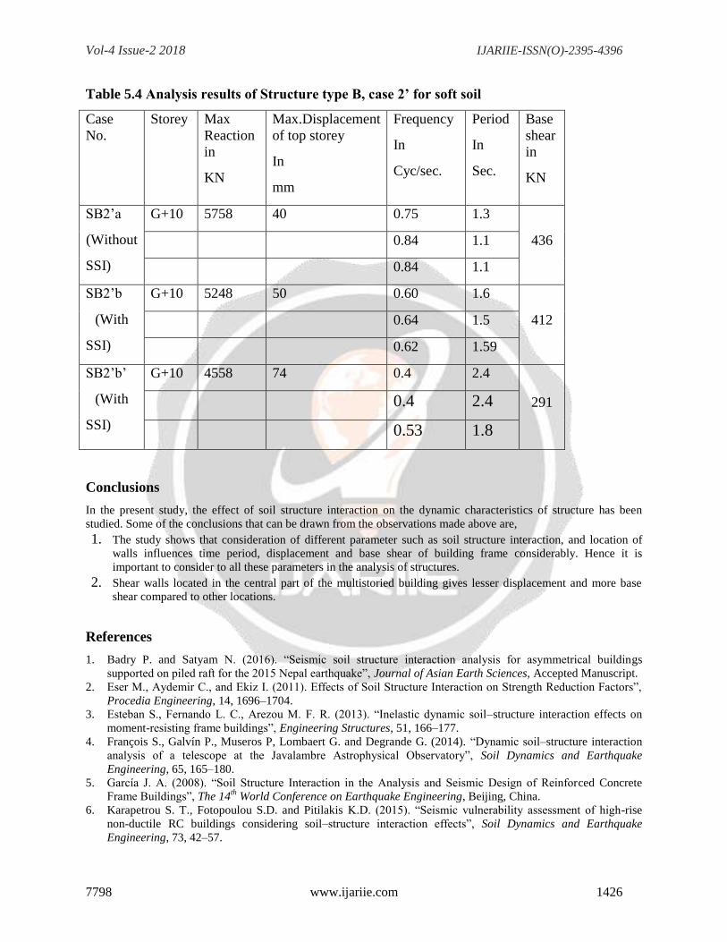
Table 5.4 Analysis results of Structure type B, case 2’ for soft soil
Case
No.
Storey Max
Reaction
in
KN
Max.Displacement
of top storey
In
mm
Frequency
In
Cyc/sec.
Period
In
Sec.
Base
shear
in
KN
SB2’a
(Without
SSI)
G+10 5758 40 0.75 1.3
436 0.84 1.1
0.84 1.1
SB2’b
(With
SSI)
G+10 5248 50 0.60 1.6
412 0.64 1.5
0.62 1.59
SB2’b’
(With
SSI)
G+10 4558 74 0.4 2.4
291 0.4 2.4
0.53 1.8
Conclusions
In the present study, the effect of soil structure interaction on the dynamic characteristics of structure has been
studied. Some of the conclusions that can be drawn from the observations made above are,
1. The study shows that consideration of different parameter such as soil structure interaction, and location of
walls influences time period, displacement and base shear of building frame considerably. Hence it is
important to consider to all these parameters in the analysis of structures.
2. Shear walls located in the central part of the multistoried building gives lesser displacement and more base
shear compared to other locations.
References
1. Badry P. and Satyam N. (2016). “Seismic soil structure interaction analysis for asymmetrical buildings
supported on piled raft for the 2015 Nepal earthquake”, Journal of Asian Earth Sciences, Accepted Manuscript.
2. Eser M., Aydemir C., and Ekiz I. (2011). Effects of Soil Structure Interaction on Strength Reduction Factors”,
Procedia Engineering, 14, 1696–1704.
3. Esteban S., Fernando L. C., Arezou M. F. R. (2013). “Inelastic dynamic soil–structure interaction effects on
moment-resisting frame buildings”, Engineering Structures, 51, 166–177.
4. François S., Galvín P., Museros P, Lombaert G. and Degrande G. (2014). “Dynamic soil–structure interaction
analysis of a telescope at the Javalambre Astrophysical Observatory”, Soil Dynamics and Earthquake
Engineering, 65, 165–180.
5. García J. A. (2008). “Soil Structure Interaction in the Analysis and Seismic Design of Reinforced Concrete
Frame Buildings”, The 14th
World Conference on Earthquake Engineering, Beijing, China.
6. Karapetrou S. T., Fotopoulou S.D. and Pitilakis K.D. (2015). “Seismic vulnerability assessment of high-rise
non-ductile RC buildings considering soil–structure interaction effects”, Soil Dynamics and Earthquake
Engineering, 73, 42–57.
Vol-4 Issue-2 2018 IJARIIE-ISSN(O)-2395-4396
7798 www.ijariie.com 1427
7. Lee J. H., Kim J. K. and Kim J. H. (2014). “Nonlinear analysis of soil–structure interaction using perfectly
matched discrete layers”, Computers and Structures, 142, 28–44.
8. Li M., Lu X, and Ye L. (2014). “Influence of soil structure interaction on seismic collapse resistance of super-
tall buildings”, Journal of Rock Mechanics and Geotechnical Engineering, 6, 477 – 485.
9. Lu Y., Hajirasouliha I. and Marshall A. M. (2016). “Performance-based seismic design of flexible-base multi-
storey buildings considering soil–structure interaction”, Engineering Structures, 108, 90–103.
10. Luco J. E. (2014). “Effects of soil–structure interaction on seismic base isolation”, Soil Dynamics and
Earthquake Engineering, 66, 167–177.
11. Massumi A. and Tabatabaiefar H.R. (2008). “A Criterion for Considering Soil-Structure Interaction Effects in
Seismic Design of Ductile RC-MRFs According to Iranian Codes”, The 14th
World Conference on Earthquake
Engineering, Beijing, China.
12. Matinmanesha H. and Asheghabadi M. S. (2011). “Seismic Analysis on Soil-Structure Interaction of Buildings
over Sandy Soil”, Procedia Engineering, 14, 1737–1743.
13. Minasidis G., Hatzigeorgiou G.D. and Beskos D.E. (2014). “SSI in steel frames subjected to near-fault
earthquakes”, Soil Dynamics and Earthquake Engineering, 66, 56–68.
14. Mitropoulou C. C., Kostopanagiotis C., Kopanos M., Ioakima D. and Lagaros N. D. (2016). “Influence of soil–
structure interaction on fragility assessment of building structures”, Structures, 6, 85–98.
15. Rajeev P. and Tesfamariam S. (2012). “Seismic fragilities of non-ductile reinforced concrete frames with
consideration of soil structure interaction”, Soil Dynamics and Earthquake Engineering, 40, 78–86.
16. Rao P. V. K., Jithu P., Sruthi S. and Krishna P. H. (2014). “Soil Structure Interaction of Building Frame
Supported by Pile Foundations Subjected to Lateral Loads”, Proceedings of Indian Geotechnical Conference
IGC-2014, Kakinada, India.
17. Raychowdhury P. (2011). “Seismic response of low-rise steel moment-resisting frame (SMRF) buildings
incorporating nonlinear soil–structure interaction (SSI)”, Engineering Structures, 33, 958–967.
18. Renzi S., Madiai C. and Vannucchi G. (2013). “A simplified empirical method for assessing seismic soil-
structure interaction effects on ordinary shear-type buildings”, Soil Dynamics and Earthquake Engineering, 55,
100–107.
19. Shanmugam J., Dode P. A. and Chore H. S. (2015). Analysis of Soil Structure Interaction in Framed
Structure”, International Journal of Computer Applications, 11 – 14.
20. Tabatabaiefar H. R. and Fatahi B. (2014). “Idealisation of soil–structure system to determine inelastic seismic
response of mid-rise building frames”, Soil Dynamics and Earthquake Engineering, 66, 339–351.
21. Tabatabaiefar H. R. and Massumi A. (2010). “A simplified method to determine seismic responses of reinforced
concrete moment resisting building frames under influence of soil–structure interaction”, Soil Dynamics and
Earthquake Engineering, 30, 1259–1267.
22. VenanziI., Salciarini D. and Tamagnini C. (2014). “The effect of soil–foundation–structure interaction on the
wind-induced response of tall buildings”, Engineering Structures, 79, 117–130.
23. K. Erol and K. K. Sashi (2007), “Assessment of current nonlinear static procedures for seismic evaluation of
buildings”, Engineering Structures, 29, 305–316.
24. Kima S. P. and Kuramab Y. C. (2008), “An alternative pushover analysis procedure to estimate seismic
displacement demands”, Engineering Structures, 30, 3793 – 3807.
25. Mwafy A.M. and Elnashai A.S. (2001), “Static pushover versus dynamic collapse analysis of RC buildings”,
Engineering Structures, 23, 407–424.
26. Ghobarah A. (2001), “Performance-based design in earthquake engineering: state of development”, Engineering
Structures, 23, 878–884.
27. Chandler A. M. and Lam N.T.K. (2001), “Performance-based design in earthquake engineering: a
multidisciplinary review”, Engineering Structures, 23, 1525–1543.
28. Maheri M.R., Kousari R. and Razazan M. (2003), “Pushover tests on steel X-braced and knee-braced RC
frames”,
29. MakariosT. K. (2005), “Optimum definition of equivalent non-linear SDF system in pushover procedure of
multistory r/c frames”, Engineering Structures, 27, 814–825.
30. Zou X.K. and Chan C.M. (2005), “Optimal seismic performance-based design of reinforced concrete buildings
using nonlinear pushover analysis”, Engineering Structures, 27, 1289–1302.
31. Borzia B., Pinhob R. and Crowleya H. (2008), “Simplified pushover-based vulnerability analysis for large-scale
assessment of RC buildings”, Engineering Structures, 30, 804–820.
32. Poursha M., Khoshnoudiana F. and Moghadamb A.S. (2009), “A consecutive modal pushover procedure for
estimating the seismic demands of tall buildings”, Engineering Structures, 31, 591 – 599.

Vol-4 Issue-2 2018 IJARIIE-ISSN(O)-2395-4396
7798 www.ijariie.com 1428
Authers and Biography