SOIL NON-LINEAR BEHAVIOR AND HYSTERETIC DAMPING IN ...
12
1 SOIL NON-LINEAR BEHAVIOR AND HYSTERETIC DAMPING IN THE SPRING-DASHPOT ANALOG Nikolaos OROLOGOPOULOS 1 and Dimitrios LOUKIDIS 2 ABSTRACT This paper presents results from numerical simulations of footing vibration examining the effect of the variation of soil shear stiffness and hysteretic damping ratio with shear strain amplitude on the values of the spring and dashpot coefficients of the Lysmer’s analog. Following validation of the numerical methodology against existing semi-analytical solutions found in the literature, a series of parametric finite element analyses are performed for vertical oscillation, horizontal oscillation and rocking of strip footings and vertical oscillation of circular footings, resting on a the free surface of a homogeneous half-space. In validation process, the soil is assumed to be a linearly elastic material, while, in the subsequent parametric study, the soil is modeled as a non-linear material following a simple hyperbolic stress-stain law with hysteresis. The study aims at establishing relationships for the determination of the spring stiffness and the dashpot coefficients for footings on fine grained soils as a function of the normalized foundation motion amplitude. INTRODUCTION The role of the foundation soil in seismic response analysis of structures is traditionally represented by simple spring and dashpot models. In most cases of soil-structure interaction simulations, the foundation soil is assumed to have constant shear stiffness (shear modulus G) and constant hysteretic damping ratio h . Numerous research studies have produced formulas and charts for the determination of the spring coefficient K and dashpot coefficient C for all possible modes of oscillation of shallow foundations, as functions of the footing size and geometry, soil elastic parameters, shear wave velocity V s and oscillation angular frequency ω (e.g., Lysmer 1965; Karashudhi et al. 1968; Luco and Westmann 1971; Veletsos and Wei 1971; Veletsos and Verbič 1973; Gazetas and Roesset 1976, 1979; Gazetas 1983; Dobry and Gazetas 1986). The spring coefficient is usually expressed as the product of the static stiffness K stat and a dynamic stiffness factor k that is a function of ω. The dashpot in such models represents mainly the radiation damping (i.e., the energy loss due to the emission of mechanical waves to the elastic half-space). The energy consumed at a material point, namely the hysteretic damping, is taken into account by applying the principle of correspondence as follows (Dobry and Gazetas 1986): h h ( ) C (1) h h 2 ( ) C C (2) 1 Research Assistant, University of Cyprus, Nicosia, Cyprus, [email protected] 2 Assistant Professor, University of Cyprus, Nicosia, Cyprus, [email protected]
Transcript of SOIL NON-LINEAR BEHAVIOR AND HYSTERETIC DAMPING IN ...

1
SOIL NON-LINEAR BEHAVIOR AND HYSTERETIC DAMPING IN
THE SPRING-DASHPOT ANALOG
Nikolaos OROLOGOPOULOS 1
and Dimitrios LOUKIDIS 2
ABSTRACT
This paper presents results from numerical simulations of footing vibration examining the effect of the
variation of soil shear stiffness and hysteretic damping ratio with shear strain amplitude on the values
of the spring and dashpot coefficients of the Lysmer’s analog. Following validation of the numerical
methodology against existing semi-analytical solutions found in the literature, a series of parametric
finite element analyses are performed for vertical oscillation, horizontal oscillation and rocking of strip
footings and vertical oscillation of circular footings, resting on a the free surface of a homogeneous
half-space. In validation process, the soil is assumed to be a linearly elastic material, while, in the
subsequent parametric study, the soil is modeled as a non-linear material following a simple
hyperbolic stress-stain law with hysteresis. The study aims at establishing relationships for the
determination of the spring stiffness and the dashpot coefficients for footings on fine grained soils as a
function of the normalized foundation motion amplitude.
INTRODUCTION
The role of the foundation soil in seismic response analysis of structures is traditionally represented by
simple spring and dashpot models. In most cases of soil-structure interaction simulations, the
foundation soil is assumed to have constant shear stiffness (shear modulus G) and constant hysteretic
damping ratio h. Numerous research studies have produced formulas and charts for the determination
of the spring coefficient K and dashpot coefficient C for all possible modes of oscillation of shallow
foundations, as functions of the footing size and geometry, soil elastic parameters, shear wave velocity
Vs and oscillation angular frequency ω (e.g., Lysmer 1965; Karashudhi et al. 1968; Luco and
Westmann 1971; Veletsos and Wei 1971; Veletsos and Verbič 1973; Gazetas and Roesset 1976,
1979; Gazetas 1983; Dobry and Gazetas 1986). The spring coefficient is usually expressed as the
product of the static stiffness Kstat and a dynamic stiffness factor k that is a function of ω. The dashpot
in such models represents mainly the radiation damping (i.e., the energy loss due to the emission of
mechanical waves to the elastic half-space). The energy consumed at a material point, namely the
hysteretic damping, is taken into account by applying the principle of correspondence as follows
(Dobry and Gazetas 1986):
h h( ) C (1)
hh
2( )C C
(2)
1 Research Assistant, University of Cyprus, Nicosia, Cyprus, [email protected]
2 Assistant Professor, University of Cyprus, Nicosia, Cyprus, [email protected]

2
It is well known that the actual soil behavior is strongly non-linear, resulting in gradual
reduction of secant shear modulus and increase of hysteretic damping ratio as the amplitude of shear
strain increases (Vucetic and Dobry 1991). Hence, it is expected that K would decrease and C would
increase with increasing amplitude of foundation displacement (or rotation for the rocking mode). This
fact is currently neglected in the standard spring-dashpot models that represent the foundation soil in
soil-structure interaction analyses in engineering practice. Nonetheless, several research efforts have
focused on introducing soil non-linearity in soil-structure interaction analysis through macro-element
modeling (e.g., Paolucci 1997; Cremer et al. 2001; Houlsby et al. 2005; Chatzigogos et al. 2009).
Moreover, significant attention has been drawn recently to the potential benefits to the structural
seismic response coming from the development of inelastic soil deformation under the foundations
and from the corresponding energy dissipation (e.g., Mergos and Kawashima 2005; Anastasopoulos et
al. 2010; Kourkoulis et al. 2012; Zafeirakos and Gerolymos 2013).
Table 1. Foundation geometries and vibration modes considered in the finite element analyses.
uyB
ux
B
uy
-uy
B
uy
B
strip footing – vertical
oscillation (plane strain)
strip footing –
horizontal oscillation
(plane strain)
strip footing - rocking
(plane strain)
circular footing - vertical
oscillation (axisymmetric)
absorbent boundary
footing
abso
rben
t bo
un
dar
y
abso
rben
t bo
un
dar
y
soil
harmonic force ( in forced vibration analysis)or initial static force (in free vibration analysis)
Figure 1. Typical finite element mesh and boundary conditions used in analyses of strip footing excited in
rocking.

N. Orologopoulos and D. Loukidis 3
This paper investigates the effect of the variation of soil stiffness and hysteretic damping ratio,
as a function of the motion amplitude, on the values of the spring and dashpot coefficients for shallow
foundation resting on the free surface of a homogeneous half-space. For this purpose, series of
parametric analyses were performed using the finite element code PLAXIS 2D (Brinkgreve et al.
2011) for vertical, horizontal and rocking oscillations of strip footings and vertical oscillation of
circular footings (Table 1), in which the soil mechanical behavior is represented by a hyperbolic
stress-strain law that predicts hysteresis. The asymptotic strength of the hyperbolic law is assumed to
be independent of the mean effective stress. Hence, the analysis results are applicable to fine grained
soils (e.g., clays, silts) under undrained conditions. In order to ensure that the employed numerical
methodology is capable of accurately simulating the problem at hand, an initial set of simulations was
performed considering the ground as a linearly elastic medium with constant hysteretic damping ratio
and the results were compared with existing semi-analytical solutions (e.g. Dobry and Gazetas 1986).
VALIDATION OF FINITE ELEMENT APPROACH
Simulations are first performed assuming that the soil is a linearly elastic medium in order to validate
the finite element methodology. Finite element results are compared with the predictions of the spring-
dashpot model for which K and C were calculated using the formulas and charts by Gazetas (1983)
and Dobry & Gazetas (1986), which are based on semi-analytical solutions and, thus, can be
considered rigorous. A large number of analyses were done for different values of Poisson’s ratio,
oscillation frequency and hysteretic damping ratio. The hysteretic damping of the soil was introduced
in the analyses through Rayleigh damping:
RayleighC M K (3)
where M and K are the global mass and stiffness matrices of the part of the finite element model
occupied by the soil (no material damping is assigned to the footing). The parameters and are
usually set to values equal to target and target/, respectively, where target is the desired material
damping ratio h at the predominant oscillation frequency of the system. These and values
essentially divide the total contribution to the material damping into two equal parts, one pertaining to
the mass (mass proportional Rayleigh damping) and the other pertaining to the stiffness (stiffness
proportional Rayleigh damping). However, this approach is not suitable for problems involving wave
propagation in a continuum, as it will be shown in the following paragraphs.
A typical finite element mesh is shown in Fig. 1, consisting of 15-noded triangular elements.
Absorbent boundary conditions are assigned to the bottom and lateral boundaries in order to diminish
reflection of the waves emitted by the foundation and achieve half-space consistent radiation damping
as much as possible. The footing has a very high Young’s modulus (practically rigid) and is fully
attached to the ground, i.e. no interface elements are placed between soil and footing. Two sets of
simulations were performed: a) forced vibration analysis and b) free vibration analysis. In forced
vibration analysis, the footing is excited by a harmonic (sinusoidal) force time history of constant
amplitude and frequency. The force is applied at the center of the footing in the case of vertical or
horizontal excitation, while a pair of vertical forces of opposite direction are applied at the edges of the
strip footing in the case of rocking in order to generate moment loading (Fig. 1). In horizontal
oscillation analyses, the footing is prevented from moving vertically or rotating. Accordingly, in
rocking analyses, the center of the footing is prevented from moving vertically or horizontally. These
footing boundary conditions were applied in order to establish pure horizontal motion and pure
rocking, which would otherwise be impossible due to the well known coupling between these two
modes of oscillation.
In free vibration analysis, the footing is first loaded statically, and, subsequently, the loading is
released (set to zero) instantaneously in order to allow the footing to vibrate freely. The mass of the
footing was selected such that the resulting motion frequency is in the range of 3Hz to 12Hz. A typical
response obtained from free vertical vibration analysis of a circular footing on soil with large
hysteretic damping is shown in Fig. 2. It was observed that the free vibration analyses give a more

4
clear picture than forced vibration analyses with respect to the damping in the soil-foundation system
and allow direct comparisons with semi-analytical solutions. The static part of these analyses was
helpful also in making comparisons regarding the static stiffness of the system and in deciding the size
of the analysis domain. This was particularly important for vertically or horizontally loaded strip
footings because, in these cases, the footing displacement is sensitive to the distance of the boundaries
from the footing.
The finite element results compare well with spring-dashpot analog predictions based on
Gazetas (1983), Dobry and Gazetas (1986) and the principle of correspondence, with differences in the
amplitude of forced vibrations not exceeding 5%. The errors are even smaller in analyses with ξh=0%,
indicating that the finite element modeling in terms of absorbent boundaries and size of analysis
domain can adequately simulate the correct radiation damping. However, the good agreement between
the finite element method (FEM) and the spring-dashpot analog based on rigorous semi-analytical
solutions is achieved on the condition that no mass proportional damping is used and the entire
material damping comes from the stiffness proportional term by setting =0 and =2h/ in Eq. (3).
In fact, setting the Rayleigh damping to be both mass and stiffness proportional, as usually done in
structural engineering practice, leads to a severe underestimation of the hysteretic damping of the soil,
as shown in the example of Fig.2.
Rayleigh damping has been originally proposed and is suitable for single degree of freedom
systems. The fact that the use of mass proportional damping in time domain analysis of multi-degree
of freedom systems is problematic has been highlighted by Hall (2006). Mass proportional damping
generates viscous forces (which consume energy) that are proportional to the absolute velocity of each
individual node of the system, as if the material point moves inside a viscous fluid exerting drag
forces. On the contrary, stiffness proportional damping generates damping forces that are proportional
to the relative motion (relative velocity) of neighboring nodes and is, thus, related to shear straining.
Hence, the stiffness proportional Rayleigh damping is closer to the physics of hysteretic damping in
problems involving wave propagation in a continuum. In such problems, in-phase “single block”
motion of the entire system is minimal and relative-differential motions dominate, and, as a result, the
mass proportional component of the Rayleigh damping is undermobilized. As a consequence, if Eq.
(3) is used with =h and =h/, the overall hysteretic damping will be underestimated, as shown
in Fig. 2. The excellent agreement between FEM (with purely stiffness proportional Rayleigh
damping) and the spring-dashpot analog is observed in all examined modes of vibration,
independently of soil elastic properties, motion frequency and ξh value. So, it can be said that the
principle of correspondence (Eq. 1 and 2) applies flawlessly to the investigated boundary value
problems.
-3.00E-04
-2.50E-04
-2.00E-04
-1.50E-04
-1.00E-04
-5.00E-05
0.00E+00
5.00E-05
1.00E-04
1.50E-04
0.0 0.1 0.2 0.3 0.4 0.5 0.6 0.7 0.8 0.9 1.0
vert
ical
dis
pla
cem
en
t u
y(m
)
t (sec)
spring-dashpot model
FEM without mass proportional damping
FEM with mass proportional damping
footing radius B =1mG=192000kPav=0.3ρ=2t/m3
h=30%f≈7.3Hz
Figure 2. Comparison of the displacement time history of free vertically oscillating circular footing predicted by
the spring-dashpot model and finite element analyses with and without mass proportional Rayleigh damping.

N. Orologopoulos and D. Loukidis 5
SOIL NON-LINEAR BEHAVIOR
The constitutive model used in the non-linear finite element analyses is the model available in
PLAXIS 2D called Hardening Soil model with small strain stiffness (HSsmall). This model combines
a shear yield surface (and a hardening cap) with pre-yield non-linear elastic behavior, thus being able
to take into account the reduction of stiffness with shear strain and also predict hysteretic behavior.
More specifically, before yielding, the material follows the hyperbolic law presented by Duncan and
Chang (1970), as modified by dos Santos and Correia (2001). The modified expression of dos Santos
and Correia (2001) for the secant shear modulus G has the following form:
max
0.7
1
1 0.385
G
G
(4)
where γ0.7 is the shear strain at which the secant shear modulus G is reduced to 72.2% of its initial
(maximum) value Gmax. During unloading and reloading, the pre-yield formulation of HSsmall obeys
the first and second Masing rules (Kramer 1996). In this study, our intention is to model soil behavior
using purely the aforementioned hyperbolic law. In order to ensure that the plastic components of the
constitutive model (yield surfaces, flow rule, e.t.c.) play no role on the material response, the material
cohesion was set to a value twice the strength asymptote predicted by the hyperbolic law. Moreover,
the soil friction angle is set equal to zero. As such, the FEM simulation results are meant to be valid
for saturated fine grained soils (e.g., clays and silts). Fig.3 shows an example of the hysteresis loop
predicted by the constitutive model in simple shear.
-300
-200
-100
0
100
200
300
-1.25 -1 -0.75 -0.5 -0.25 0 0.25 0.5 0.75 1 1.25τ xy
(kP
a)
γxy (%)
Figure 3. Hysteresis loop of soil material under simple shear loading as predicted by HSsmall.
The parameter γ0.7 controls the curvature of the shear stress-strain response (backbone curve).
This allows to fit, to the extent possible, the G/Gmax vs. γ and h vs. γ curves predicted by the HSmall
model to the experimental curves of Vucetic and Dobry (1991) for various values of the soil plasticity
index PI. Three different PI values are considered in this study, PI=5, 20 and 40, with the
corresponding γ0.7 values that fit the Vucetic and Dobry (1991) curves being 0.00025, 0.0005 and
0.0008, respectively. The hyperbolic law of Eq. (4) yields zero hysteretic damping for very small shear
strain amplitudes. On the other hand, experimental studies show that there is a minimum non-zero

6
0
0.1
0.2
0.3
0.4
0.5
0.6
0.7
0.8
0.9
1
0.001 0.01 0.1 1
G/G
ma
x
(%)
Plaxis
Vucetic & Dobry (1991)
PI=5
0.7=0.00025
(a)
0
5
10
15
20
25
30
35
40
45
50
0.001 0.01 0.1 1
h
(%)
(%)
Plaxis
Vucetic & Dobry (1991)
PI=5
0.7=0.00025 (b)
Figure 4. Comparison of experimental curves and HSsmall model predictions for PI=5.
0
0.1
0.2
0.3
0.4
0.5
0.6
0.7
0.8
0.9
1
0.001 0.01 0.1 1
G/G
ma
x
(%)
Plaxis
Vucetic and Dobry (1991)
PI=20
0.7=0.0005
(a)
0
5
10
15
20
25
30
35
40
45
0.001 0.01 0.1 1
h
(%)
(%)
Plaxis
Vucetic & Dobry (1991)
PI=20
0.7=0.0005 (b)
Figure 5. Comparison of experimental curves and HSsmall model predictions for PI=20.
0
0.1
0.2
0.3
0.4
0.5
0.6
0.7
0.8
0.9
1
0.001 0.01 0.1 1
G/G
ma
x
(%)
Plaxis
Vucetic & Dobry (1991)
PI=40
0.7=0.0008
(a)
0
5
10
15
20
25
30
35
40
0.001 0.01 0.1 1
h
(%)
(%)
Plaxis
Vucetic and Dobry (1991)
PI=40
0.7=0.0008(b)
Figure 6. Comparison of experimental curves and HSsmall model predictions for PI=40.

N. Orologopoulos and D. Loukidis 7
value for h even at practically zero shear strain. Hence, along with HSsmall, a small amount of
Rayleigh damping (stiffness proportional) was assigned to the soil in order to achieve a minimum h of
1%.
Figs. 4 through 6 compare HSsmall predictions in simple shear at material point level against
the experimental observations (Vucetic and Dobry 1991). Effort was made to have the closest possible
agreement in terms of both G/Gmax vs. γ and h vs. γ curves. As a result, the G/Gmax reduction is
generally under-predicted at the small strain range in order to not excessively over-predict h. Yet, the
over-prediction of h at γ>0.1% is inevitably large. All non-linear analyses were performed for
Poisson's ratio v=0.495, assuming that the fine grained soil is fully saturated by capillary suction or by
being under the water table.
NON-LINEAR ANALYSIS
The non-linear finite element analyses focus mainly on the effects of foundation size (half-width B
ranging from 0.5m to 4m), Gmax (50, 100 and 200MPa) , PI (5, 20 and 40) and oscillation frequency f
(in the range 3Hz to 12Hz). Given the values assumed for the parameter γ0.7 of the hyperbolic law, the
(asymptotic) undrained shear strength su of the soil ranges from 32kPa to 416kPa, and the
corresponding Gmax/su ratio from 480 to 1540. First, static parametric analyses were performed, in
which the footing was loaded statically in order to obtain the reduction of the equivalent secant spring
coefficient Kequ and establish curves of Kequ/Kmax as a function of the normalized foundation
displacement amplitude u/2B (B: footing half-width). Kmax is the spring coefficient corresponding to
the maximum shear modulus Gmax.
To determine the equivalent hysteretic damping ratio h,equ of the soil-foundation system, free
vibration analyses were performed for various levels of initial load amplitude. For each analysis, the
total damping ratio tot of the system (radiation + hysteretic) was first extracted from the displacement
time history (Fig. 7) using the well known logarithmic decrement method:
n n+1
tot,(n)2 2
n n+1
=ln /
ln / 4
u u
u u
(5)
un+1un
1.5
1.5
Figure 7. Determination of the damping ratio of a system from free vibration response.
The representative displacement amplitude corresponding to tot,(n) (tot value calculated for the nth
cycle) is assumed to be equal to u(n)=(un+un+1)/2. Given Eq. (1), Eq. (2) and that
tot h h0.5 ( ) ( )/C K , the equivalent hysteretic damping ratio of the soil-foundation system can be
determined from the following equation:

8
tot
tot
equ
h,equ
equ
0.5=
K k C
K k C
(6)
with C and k obtained from Dobry and Gazetas (1986) and the Kequ value corresponding to u(n). It was
observed that the h,equ yielded by Eq. (6) was very close to the value obtained if we assume simple
superposition of radiation and hysteretic damping:
h,equ tot rad tot
equ2
C
K k
(7)
There are several pairs of displacement amplitude in a free vibration decay (such as the one
shown in Fig. 7) that can be used for the calculation of h,equ. The earlier cycles yield larger damping
ratios since they correspond to larger displacement amplitudes (and, consequently, larger average
shear strain in the soil in the vicinity of the footing) than later cycles. By bringing together these
results from several analyses in a graph, scatter plots are formed, as shown in Fig.8. It is interesting to
note that the trend lines that fit closely the data points are actually linear functions of the footing
displacement (or rotation in this particular case); they appear curved due to the logarithmic scale of
the horizontal axis. Such trend lines of h,equ vs. u/2B are plotted in Fig. 9 and 10 for all parametric
analyses performed for vertical oscillation of circular footing and rocking of strip footing, along with
the respective stiffness reduction curves from static analyses.
0
5
10
15
20
25
0.0001 0.001 0.01 0.1
h
,eq
u (%
)
u/(2B) = /2 (%)
1kN
10kN
25kN
50kN
100kN
trend line (=120θ+0.92)
load
am
plit
ud
ein
itia
l
0
5
10
15
20
25
0.0001 0.001 0.01 0.1
h
,eq
u (%
)
u/(2B) = /2 (%)
1kN
10kN
25kN
50kN
100kN
200kN
trend line (=119.5θ+1.13)
load
am
plit
ud
ein
itia
l
Figure 8. Scatter plots of equivalent hysteretic damping ratio h,equ as a function of the normalized footing edge
displacement amplitude u/2B for strip footing in rocking from analyses with: a) B=0.5m, Gmax=200MPa, PI=20,
f=12Hz, b) B=1m, Gmax=100MPa, PI=20, f=6Hz)
Due the inherently very large radiation damping exhibited in the case of vertically or
horizontally oscillating footings, extraction of h,equ from free vibration analyses for these two modes
was found unreliable. This is because of the very small displacement amplitudes left after the first
cycle as a result of extreme decay. Moreover, the absorbent boundaries in the vertical or horizontal
free vibration analyses exhibited significant permanent displacements. For these reasons, the h,equ for
these two strip footing oscillation modes was extracted from the area of the load-displacement
hysteresis loop from analyses where the footing was cycled quasi-statically, as shown in Fig. 11. The
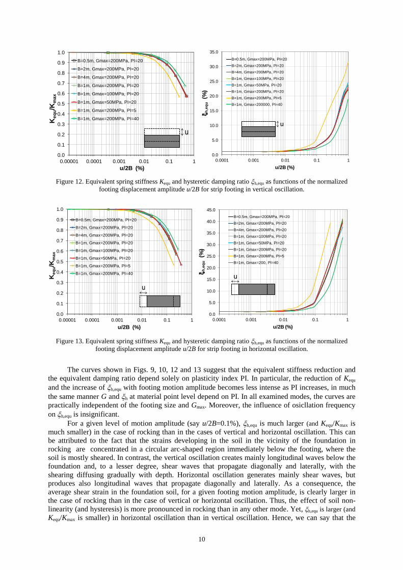
resulting equivalent spring stiffness and hysteretic damping ratio as functions of u/2B are presented in
Figs. 12 and 13. The constitutive model employed herein predicts zero hysteretic damping at very
small shear strains and, thus, quasi-static analyses produce zero h,equ for very small footing motion
amplitudes. Hence, a value of 1% was added to the quasi-static FEM results in order to be able to
make direct comparisons between Figs. 12 and 13 and Fig. 9 and 10.

N. Orologopoulos and D. Loukidis 9
0.0
0.1
0.2
0.3
0.4
0.5
0.6
0.7
0.8
0.9
1.0
0.00001 0.0001 0.001 0.01 0.1
Ke
qu/K
ma
x
u/2B (%)
B=0.5m, Gmax=200MPa, PI=20
B=2m, Gmax=200MPa, PI=20
B=1m, Gmax=200MPa, PI=20
B=1m, Gmax=100MPa, PI=20
B=1m, Gmax=50MPa, PI=20
B=1m, Gmax=200MPa, PI=5
B=1m, Gmax=200MPa, PI=40
u
0.0
1.0
2.0
3.0
4.0
5.0
6.0
7.0
0.00001 0.0001 0.001 0.01 0.1
h
,eq
u(%
)
u/2B (%)
B=0.5m, Gmax=200000, PI=20, f=12Hz
B=2m, Gmax=200MPa, PI=20, f=3Hz
B=4m, Gmax=200MPa, PI=20, f=3Hz
B=1m, Gmax=200MPa, PI=20, f=3Hz
B=1m, Gmax=100MPa, PI=20, f=6Hz
B=1m, Gmax=50MPa, PI=20, f=4.2Hz
B=1m, Gmax=200MPa, PI=5, f=8.5Hz
B=1m, Gmax=200MPa, PI=40, f=8.5Hz
B=1, Gmax=200MPa, PI=20, f=8.5Hz
u
Figure 9. Equivalent spring stiffness Kequ and hysteretic damping ratio h,equ as functions of the normalized
footing displacement amplitude u/2B for circular footing in vertical oscillation.
0.0
0.1
0.2
0.3
0.4
0.5
0.6
0.7
0.8
0.9
1.0
0.00001 0.0001 0.001 0.01 0.1
Ke
qu/K
ma
x
u/2B = /2 (%)
B=0.5m, Gmax=200000, PI=20
B=2m, Gmax=200000, PI=20
B=4m, Gmax=200000, PI=20
B=1m, Gmax=200000, PI=20
B=1m, Gmax=100000, PI=20
B=1m, Gmax=50000, PI=20
B=1m, Gmax=200000, PI=5
B=1m, Gmax=200000, PI=40
u
-u
0.0
5.0
10.0
15.0
20.0
25.0
30.0
0.00001 0.0001 0.001 0.01 0.1
h
,eq
u(%
)
u/2B = /2 (%)
B=0.5m, Gmax=200MPa, PI=20, f=12Hz
B=2m, Gmax=200MPa, PI=20, f=3Hz
B=4m, Gmax=200MPa, PI=20, f=3Hz
B=1m, Gmax=200MPa, PI=20, f=3Hz
B=1m, Gmax=100MPa, PI=20, f=6Hz
B=1m, Gmax=500MPa, PI=20, f=4.2Hz
B=1m, Gmax=200MPa, PI=20, f=8.5Hz
B=1m, Gmax=200MPa, PI=5, f=8.5Hz
B=1m, Gmax=200MPa, PI=40, f=8.5Hz
u
-u
Figure 10. Equivalent spring stiffness Kequ and hysteretic damping ratio h,equ as functions of the normalized
footing edge displacement amplitude u/2B for strip footing in rocking.
-2000
-1500
-1000
-500
0
500
1000
1500
2000
-0.02 -0.015 -0.01 -0.005 0 0.005 0.01 0.015 0.02
F (kN
)
u (m)
WD
WS
Dh,equ
S4
W
W
Figure 11. Typical hysteresis loop from quasi-static analysis of strip footing subjected to vertical cycling.
10
0.0
0.1
0.2
0.3
0.4
0.5
0.6
0.7
0.8
0.9
1.0
0.00001 0.0001 0.001 0.01 0.1 1
Ke
qu/K
ma
x
u/2B (%)
B=0.5m, Gmax=200MPa, PI=20
B=2m, Gmax=200MPa, PI=20
B=4m, Gmax=200MPa, PI=20
B=1m, Gmax=200MPa, PI=20
B=1m, Gmax=100MPa, PI=20
B=1m, Gmax=50MPa, PI=20
B=1m, Gmax=200MPa, PI=5
B=1m, Gmax=200MPa, PI=40
u
0.0
5.0
10.0
15.0
20.0
25.0
30.0
35.0
0.0001 0.001 0.01 0.1 1
h
,eq
u(%
)
u/2B (%)
B=0.5m, Gmax=200MPa, PI=20
B=2m, Gmax=200MPa, PI=20
B=4m, Gmax=200MPa, PI=20
B=1m, Gmax=100MPa, PI=20
B=1m, Gmax=50MPa, PI=20
B=1m, Gmax=200MPa, PI=20
B=1m, Gmax=200MPa, PI=5
B=1m, Gmax=200000, PI=40
u
Figure 12. Equivalent spring stiffness Kequ and hysteretic damping ratio h,equ as functions of the normalized
footing displacement amplitude u/2B for strip footing in vertical oscillation.
0.0
0.1
0.2
0.3
0.4
0.5
0.6
0.7
0.8
0.9
1.0
0.00001 0.0001 0.001 0.01 0.1 1
Ke
qu/K
ma
x
u/2B (%)
B=0.5m, Gmax=200MPa, PI=20
B=2m, Gmax=200MPa, PI=20
B=4m, Gmax=200MPa, PI=20
B=1m, Gmax=200MPa, PI=20
B=1m, Gmax=100MPa, PI=20
B=1m, Gmax=50MPa, PI=20
B=1m, Gmax=200MPa, PI=5
B=1m, Gmax=200MPa, PI=40
u
0.0
5.0
10.0
15.0
20.0
25.0
30.0
35.0
40.0
45.0
0.0001 0.001 0.01 0.1 1
h
,eq
u(%
)
u/2B (%)
B=0.5m, Gmax=200MPa, PI=20
B=2m, Gmax=200MPa, PI=20
B=4m, Gmax=200MPa, PI=20
B=1m, Gmax=100MPa, PI=20
B=1m, Gmax=50MPa, PI=20
B=1m, Gmax=200MPa, PI=20
B=1m, Gmax=200MPa, PI=5
B=1m, Gmax=200, PI=40
u
Figure 13. Equivalent spring stiffness Kequ and hysteretic damping ratio h,equ as functions of the normalized
footing displacement amplitude u/2B for strip footing in horizontal oscillation.
The curves shown in Figs. 9, 10, 12 and 13 suggest that the equivalent stiffness reduction and
the equivalent damping ratio depend solely on plasticity index PI. In particular, the reduction of Kequ
and the increase of h,equ with footing motion amplitude becomes less intense as PI increases, in much
the same manner G and h at material point level depend on PI. In all examined modes, the curves are
practically independent of the footing size and Gmax. Moreover, the influence of osicllation frequency
on h,equ is insignificant.
For a given level of motion amplitude (say u/2B=0.1%), h,equ is much larger (and Kequ/Kmax is
much smaller) in the case of rocking than in the cases of vertical and horizontal oscillation. This can
be attributed to the fact that the strains developing in the soil in the vicinity of the foundation in
rocking are concentrated in a circular arc-shaped region immediately below the footing, where the
soil is mostly sheared. In contrast, the vertical oscillation creates mainly longitudinal waves below the
foundation and, to a lesser degree, shear waves that propagate diagonally and laterally, with the
shearing diffusing gradually with depth. Horizontal oscillation generates mainly shear waves, but
produces also longitudinal waves that propagate diagonally and laterally. As a consequence, the
average shear strain in the foundation soil, for a given footing motion amplitude, is clearly larger in
the case of rocking than in the case of vertical or horizontal oscillation. Thus, the effect of soil non-
linearity (and hysteresis) is more pronounced in rocking than in any other mode. Yet, h,equ is larger (and
Kequ/Kmax is smaller) in horizontal oscillation than in vertical oscillation. Hence, we can say that the

N. Orologopoulos and D. Loukidis 11
horizontal vibration case lies between rocking and vertical vibration in terms of importance of soil
non-linearity.
CONCLUSIONS
A series of parametric analyses were performed using the finite element method (FEM) in order to
determine equivalent values for the spring stiffness and hysteretic damping ratio that account for soil
non-linearity in the standard spring-dashpot model. The finite element methodology was validated by
first performing analyses in which the soil was linearly elastic with Rayleigh damping. Numerical
results are in agreement with the predictions of the spring-dashpot model using coefficients based on
semi-analytical solutions. It was observed that use of both mass and stiffness proportional Rayleigh
damping leads to severe underestimation of the soil hysteretic damping. Hence, if possible, only
stiffness proportional damping should be used in analyses involving wave generation and propagation
in a continuum.
Finite element analyses performed assuming that the soil follows a hyperbolic stress-strain law
with hysteresis show that the equivalent spring stiffness reduces and the equivalent (average)
hysteretic damping ratio of the foundation-soil system increases with increasing motion amplitude, in
practically the same manner as in the case of a sheared soil element. However, for the same order of
displacement amplitude, the rocking mode exhibits significantly larger equivalent hysteretic damping
ratio than the vertical or horizontal oscillation modes. Accordingly, the stiffness reduction is more
intense in the case of rocking. Regardless of the type of oscillation, the equivalent spring stiffness
reduction and hysteretic damping curves depend strongly on the plasticity index PI of the soil, but not
on foundation size, maximum shear modulus or oscillation frequency.
Finally, the findings of the present study suggest that the effect of the foundation motion
amplitude on the spring stiffness and dashpot coefficients is important and may result in a significant
reduction of the spectral acceleration in soil-structure interaction computations, mostly due to the
increased hysteretic damping ratio caused by the rocking mode. However, we must stress the fact that
the constitutive model used herein to simulate non-linear soil behavior over-predicts significantly the
hysteretic damping ratio at shear strain amplitudes larger than 0.1%, which may be operative in soil-
structure interaction problems involving strong earthquake shaking. Hence, the findings reported in
this paper need to be verified by analyses using a constitutive model that captures soil hysteresis
accurately in the entire shear strain range.
REFERENCES
Anastasopoulos I, Gazetas G, Loli M, Apostolou M, Gerolymos N (2010) "Soil failure can be used for seismic
protection of structures", Bulletin of Earthquake Engineering, 8(2):309–326.
Brinkgreve RBJ, Swolfs WM and Engin E (2011) PLAXIS 2D Reference manual, Delft, The Netherlands.
Chatzigogos CT, Pecker A, Salencon J (2009) "Macroelement modeling of shallow foundations", Soil Dynamics
and Earthquake Engineering, 29(5): 765–781.
Cremer C, Pecker A, and Davenne L (2001). "Cyclic macro‐element for soil–structure interaction: material and
geometrical non‐linearities" International Journal for Numerical and Analytical Methods in
Geomechanics, 25(13): 1257-1284.
Dobry R and Gazetas G (1986), "Dynamic response of arbitrarily shaped foundations", Journal of geotechnical
engineering, 112(2): 109-135.
Dobry R and Gazetas G "Dynamic response of arbitrarily shaped foundations." Journal of geotechnical
engineering 112.2 (1986): 109-135.
Dos Santos JA and Correia AG (2001) "Reference threshold shear strain of soil. Its application to obtain an
unique strain-dependent shear modulus curve for soil", Proceedings of the 15th International Conference
on Soil Mechanics and Geotechnical Engineering, Istanbul, Turkey, AA Balkema.
Duncan JM and Chang C-Y (1970) "Nonlinear analysis of stress and strain in soils", Journal of the Soil
Mechanics and Foundations Division, 96(5): 1629-1653.

12
Gazetas GC and Roesset JM (1976) "Forced vibrations of strip footings on layered soils." Methods of Structural
Analysis, ASCE: 115-131.
Gazetas GC and Roesset JM (1979) "Vertical vibration of machine foundations" Journal of the Geotechnical
Engineering Division, 105(12): 1435-1454.
Gazetas G (1983) "Analysis of machine foundation vibrations: state of the art." International Journal of Soil
Dynamics and Earthquake Engineering 2(1): 2-42.
Gazetas G (1991) "Foundation vibrations", Chapter 15, Foundation engineering handbook, ed. Fang HY,
Springer: 553-593.
Hall JF. (2006) "Problems encountered from the use (or misuse) of Rayleigh damping." Earthquake engineering
& structural dynamics, 35(5): 525-545.
Houlsby GT, Cassidy MJ and Einav I (2005) "A generalised Winkler model for the behaviour of shallow
foundations" Géotechnique, 55(6): 449-460.
Karasudhi PL, Keer M and Lee SL (1968) "Vibratory motion of a body on an elastic half plane." Journal of
Applied Mechanics, 35: 697-705.
Kourkoulis R, Gelagoti F and Anastasopoulos I (2012) "Rocking isolation of frames on isolated footings: design
insights and limitations" Journal of Earthquake Engineering, 16(3): 374-400.
Kramer SL (1996) Geotechnical earthquake engineering, Prentice Hall.
Luco JE and Westmann RA (1971) "Dynamic response of circular footings", Journal of the Engineering
Mechanics Division, 97(5), 1381-1395.
Lysmer J (1965) Vertical motion of rigid footings, Final Report. University of Michigan, Ann Arbor, Collection
of Engineering.
Mergos PE and Kawashima K (2005). "Rocking isolation of a typical bridge pier on spread foundation", Journal
of Earthquake Engineering, 9(sup2): 395-414.
Orologopoulos N (2013) Non-linear behavior and hysteretic damping of soils in the spring-dashpot model, MSc
Thesis, University of Cyprus.
Paolucci R (1997) "Simplified evaluation of earthquake-induced permanent displacements of shallow
foundations" Journal of Earthquake Engineering, 1(3): 563-579.
Veletsos AS and Wei YT (1971) "Lateral and rocking vibration of footings", Journal of Soil Mechanics &
Foundations Div, 97(9): 1227-1248.
Veletsos AS and Verbič B (1974) "Basic response functions for elastic foundations", Journal of the Engineering
Mechanics Division, 100(2): 189-202.
Vucetic M and Dobry R (1991) "Effect of soil plasticity on cyclic response", Journal of Geotechnical
Engineering, 117(1): 89-107.
Zafeirakos A and Gerolymos N (2013) "On the seismic response of under-designed caisson foundations",
Bulletin of Earthquake Engineering, 11(5): 1337-1372.