
Soil Nails Reinforcement - Design nails soil stabilization --مسامير قضبان تسليح...
93
1 SOIL NAILING : Software SNAP-2 (Soil Nail Analysis Program) https://www.fhwa.dot.gov/engineering/geotech/software/snap2/snap2.zip Dr Hammida
-
Upload
dryoussef-hammida -
Category
Technology
-
view
1.484 -
download
3
Transcript of Soil Nails Reinforcement - Design nails soil stabilization --مسامير قضبان تسليح...

1
SOIL NAILING
:Software
SNAP-2 (Soil Nail Analysis Program)
https://www.fhwa.dot.gov/engineering/geotech/software/snap2/snap2.zip
Dr Hammida
2
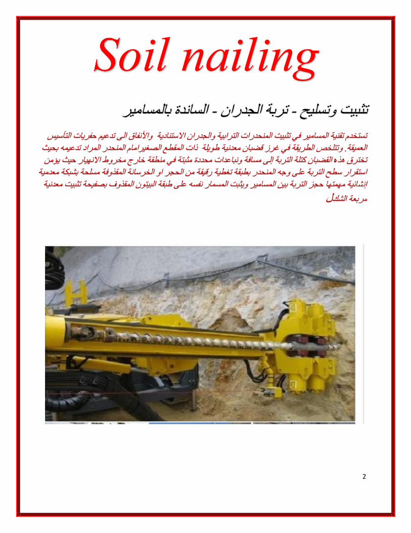
Soil nailing
رالساندة بالمسامی - تربة الجدران -وتسلیح ثبیتت
التأسیس یاترحف تدعیم الى واألنفاق ادیة الجدران االستنو تستخدم تقنیة المسامیر في تثبیت المنحدرات الترابیةالمنحدر المراد تدعیمھ بحیث الصغیرامام المقطع ذات معدنیة طویلة قضبانفي غرز الطریقة العمیقة. وتتلخص
یؤمن حیث مثبتة في منطقة خارج مخروط االنھیار محددة ونباعدات كتلة التربة إلى مسافة القضبان هذتخترق ھ معدمیة مسلحة بشبكة ةمقذوفالحجر او الخرسانة ال على وجھ المنحدر بطبقة تغطیة رقیقة من التربةاستقرار سطح
إنشائیة مھمتھا حجز التربة بین المسامیر ویثبت المسمار نفسھ على طبقة البیتون المقذوف بصفیحة تثبیت معدنیة
لمربعة الشك

3
Soil nail wall - Soil nailing - soil nailing walls
Soil nailing is an earth retention technique using grouted tension-resisting steel
elements (nails) that can be design for permanent or temporary support. The walls
are generally constructed from the top down. Typically, 3 to 6 feet of soil is
excavated from the top of the planned excavation. Near-horizontal holes are drilled
into the exposed face at typically 3 to 6 foot centers. Tension-resisting steel bars are
inserted into the holes and grouted. A drainage system is installed on the exposed
face, followed by the application of reinforced shotcrete facing. Precast face

4
been used instead of shotcrete. Bearing plates are then fixed to the heads of the soil
nails. The soil at the base of this first stage is then removed to a depth of about 3 to 6
feet. The installation process is repeated until the design wall depth is reached. The
finished soil nails produce a zone of reinforced ground.

5

6

7

8

9

10
details of a soil nail wall:

11
Figure 1: Typical soil nail wall arrangement
Soil nail wall construction proceeds from the top to bottom, and head plates are
installed on each nail. Shotcrete or concrete is typically applied on the excavation
face to provide continuity when a soil nail wall is constructed. For a soil nail wall
the general construction procedure involves:
What is Soil Nailing?
Soil nailing is a technique used to bring soil stability in areas where landslides might be a problem. Soil nail can prevent landslides by inserting steel reinforcement bars into the soil and anchoring them to the soil strata. It is called Soil Nail, because it’s like having a nail being hammered into the soil, where the nails, are the steel bars

12
Soil nail provides a resisting force against slope failures.
- Its construction process is faster than other similar methods. The
construction procedure starts, drilling into the soil, where the nail, steel
bar, is going to be placed. After the drilling has been completed, exact
depth must be provided by the geotechnical engineer, the nail must be
inserted into the drilled hole. Then, it must be grouted into the soil to
create a structure similar to a gravity wall. After placing the nail, a shot-
Crete layer is usually placed as a facing material, to protect the exposed
nail, and then other architectural options are placed over the shot-Crete,
creating an aesthetic finish to the project.
- The grouted soil nail hole typically has a minimum diameter of 4
inches. Centralizers are placed around the soil nail to maintain an
even thickness of grout around the bar. For permanent
applications, nails may be epoxy-coated or provided with a
protective sheath for corrosion protection

13
SOIL NAILING
Soil nail concept: Unlike the ground anchor that stresses to "seal" the ground, soil nail is "passive", that is, it develops tension only as the ground deforms laterally. Soil nails are normally used to stabilise natural or
excavation slopes.

14
1) face failure seems to be a structural failure of the concrete facing, mostly
un-related to the soil nail or screw. If you are able to successfully install the
nail and facing, then face failure should not happen.
2) screws may have more uniform tension along nearly the entire length of
the rod, as the anchoring helix is generally on the end.
3) screws do not impart as much stress into the looser surface zones,
instead they only anchor in the competent material where the helices are.

15

16
Strand Anchor post Tension - شد الحق

17
18

19

20
Strand Anchor

21
The difference is in soil nails vs. tieback anchors
Soil nails are usually shorter with much lower lower design loads than
tieback anchors. In length, soil nails usually are between 70% AND
100% x the wall height.
Grouted tieback anchors are usually longer than 30 feet with 40 to 60
feet being more normal for most applications . Sometimes, tieback
anchors are much, much longer than 60 feet.
Soil nails are usually installed at closer spacings than tiebacks. Nails
may be installed at an area of approximately 25 SF per nail (5' x 5')
while tiebacks may be installed at an area of approximately 120 SF per
nail (sometimes more, sometimes less).
Tiebacks are active support members. They push on the retained soil
harder than the earth and surcharge pressures would push on the
wall. Soil nails are passive support members. They provide their
support as the soil mass begins to mobilize.
Both soil nails and tieback anchors might have similar corrosion
protection details. Every tieback anchor is usually proof or
performance tested.
Most soil nails are not tested. Usually a small percentage of the nails
are tested or non-production nails are tested.
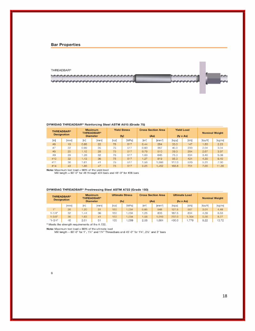
Soil nail tendons are usually Grade 60 or 75 threadbar
tendons. Tieback tendons are usually either threadbar tendons (Grade
60 to Grade 160) or multi-strand tendons (Grade 270).
Soil nail walls are soldier beamless walls. Shotcrete and nails are the
support. There may be a second or permanent facing of shotcrete or
even a precast facing attached to the nails.

22
Tiedback walls often use soldier beams, lagging, and tiebacks with a
precast or cast in place concrete permanent facing when required.
Soil nail walls become economical when the retained soils have a little
cohesion and when it may be expensive to install soldier
beams. Uncontrolled ground water can be a big problem when
constructing either tiedback or soil nail walls.
Both tiedback and soil nail walls are meant to be constructed from the
top down, in a cut situation.
If your wall is a fill or embankment wall, anchored walls are usually not
the best wall type. Try an MSE wall or conventional concrete wall. Tiebacks can be made in most types of soil except soft clays and silts, and in all types of rock. The capacity of the anchors in soil will vary depending upon grain size and installation method. The denser, granular soils will typically produce higher capacity tiebacks. We have installed tiebacks with lengths in excess of 200 feet and tested capacities of over 500 kip for landslide stabilization
Soil Nailing works – 1

23
The excavations work has left a 4.5 meter high 60° battered banking to the rear of the proposed dwellings. The banking is to be retained by driving 5 meter long steel nails into the ground at 1 meter centres. ‘
Soil Nailing works – 1-1
Deep excavationEarth nailingEarth protectionEarth work ExcavationShore protectionsoil nailing The excavations work has left a 4.5 meter high 60° battered banking to the rear of the proposed dwellings. The banking is to be retained by driving 5 meter long steel nails into the ground at 1 meter
centres.

24
‘X’ marks the spot.

25
once all the nails are in place they will be covered with a stone wall.
Soil nailing – 2
The basic principle of soil nailing is to place rebar into the
natural soil in an effort to increase its tensile strength and shear
strength. Soil nailing is used when the natural soil has adequate
compressive

26
Soil nailing – 2-1

27
Soil nailing is used when the natural soil has adequate compressive strength, but low levels of tensile and shear strength. In this condition, soil nailing serves to improve the load-bearing behavior of the natural soil.
The original subsoil is therefore turned into a composite body which, in terms of load-bearing behavior, is similar to a gravity wall capable of taking up external forces so that the soil is integrated into the structure as a structural component.
Soil Nails – 3
Construction of a Soil Nail Wall Excavate soil Drill hole Install and grout nail Test selected nails Place reinforcement Place shotcrete Finish shotcrete Install Did, than brand

28
Soil nail wall construction sequence

29

30

31

32

33

34

35

36

37

38

39

40

41
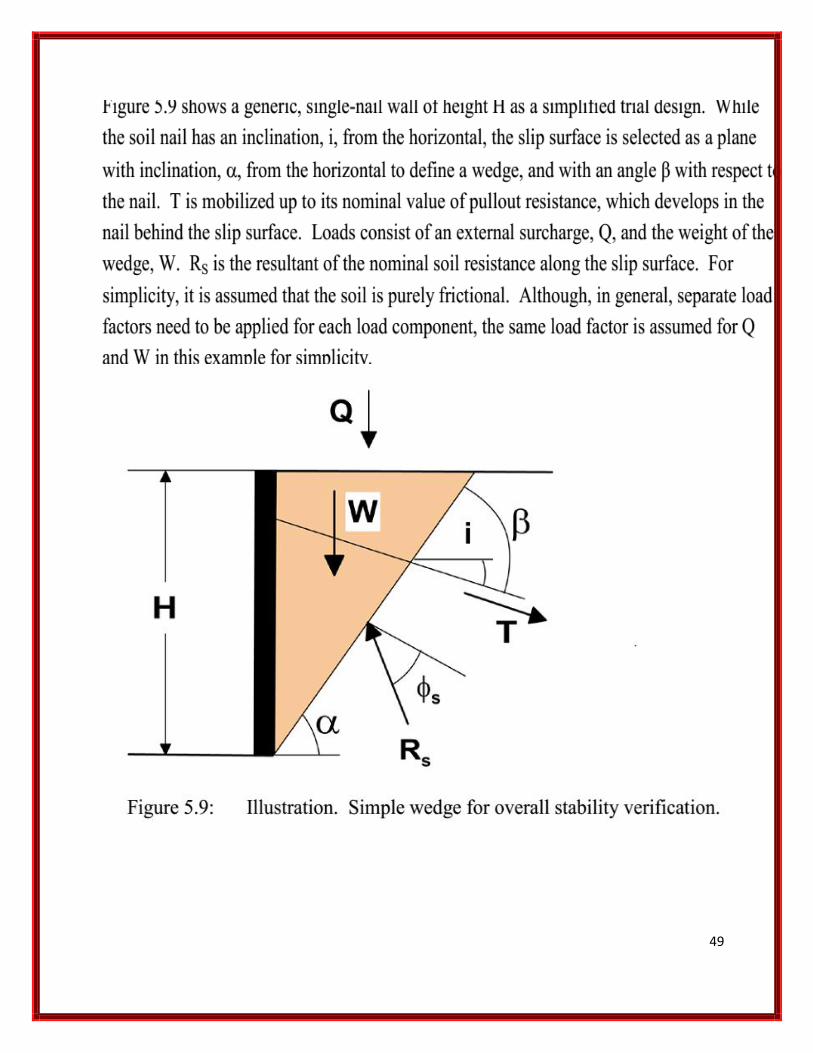
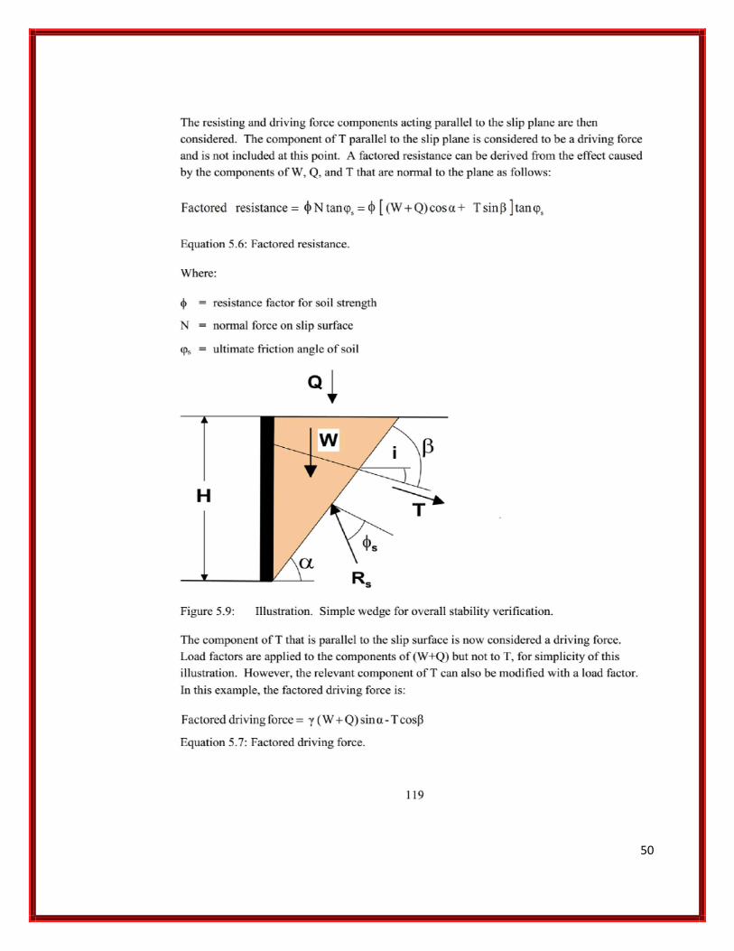
Wedge analysis – Nails Design The equilibrium of a simple triangular active failure wedge behind the excavation
face was examined to estimate the development of axial soil nail forces in response to
the deepening excavation (Figure 10).
This approach is commonly used for soil nail design, although the complexity of the
mechanisms varies (SAICE 1989). For the
problem modelled in the centrifuge, only three forces were considered: the self-weight
of the failure wedge = (W)
the resisting force mobilised on the failure plane (R) and the sum of the individual
soil nail forces (T).
For a fully mobilised failure mechanism the resisting force R would act at an angle φ
as shown in Figure 10, where φ is the soil friction angle. The soil nails were assumed
to carry only axial loads, disregarding any bending or shear stiffness they might
possess.
The failure wedge was assumed to mobilise at a slope angle β. This slope anglew as
varied to find the maximum axial soil nail force (T). For a horizontal soil surface and
smooth vertical retaining wall, the wedge analysis provides the same solution as the
active Rankine earth pressure case
The soil nail loads were calculated for various depths of excavation by simply
dividing the total calculated soil nail force (T) by the number of nails intersecting the
failure wedge. The calculated forces (based on horizontal soil nails) are plotted with
the observed loads. As no failure wedge intersects soil nails for excavation depths of
up to 30 mm (1.5 m at prototype scale), zero soil nail force was assumed up to this
depth.

42
Nails Reinforcement Design
self-weight of the failure wedge = (W )
43
nail force = (T )
active Rankine earth pressure =( R )

44

45

46

47
SMSE wall for steep terrain.

48
49
50

51

52

53

54

55

56

57

58

59

60

61

62

63

64

65

66

67

68

69

70

71

72

73

74

75

76

77

78

79

80

81

82

83

84

85
86

87

88
ادخال المعلومات الى الحاسب والمقارنة مع الحل الیدوي

89

90

91

92

93
Dr Hammida


![Fundamentals of soil stabilization - Springer · Fundamentals of soil stabilization ... [5453].Zulkieyetal.[, 55] ... however,thePIshouldnotbegreaterthan25.Soils](https://static.fdocuments.us/doc/165x107/5b60a3d07f8b9a3b488b8193/fundamentals-of-soil-stabilization-springer-fundamentals-of-soil-stabilization.jpg)