The Oklahoma Mesonet’s Soil Temperature and Soil Moisture Networks
Second Pan American Geosynthetics Conference & Exhibition GeoAmericas 2012
Lima, Peru - May 2012
SOIL CONFINEMENT AND TEMPERATURE EFFECTS ON GEOSYNTHETICS CREEP BEHAVIOR F.A.N. Franca, Department of Geotechnical Engineering, São Carlos School of Engineering, University of São Paulo, São Carlos, Brazil B.S. Bueno, Department of Geotechnical Engineering, São Carlos School of Engineering, University of São Paulo, São Carlos, Brazil, J.G. Zornberg, Department of Civil, Architectural and Environmental Engineering, University of Texas at Austin, Austin, United States. ABSTRACT The creep behavior of geosynthetics is usually determined by means of standard tests in which a geosynthetic specimen is subjected to a constant load while its elongation is registered. These tests present two main concerns: duration and lack of soil-geosynthetic interaction. A new creep apparatus was developed to mitigate both aspects simultaneously. Preliminary creep tests were conducted using a polyester non-woven geotextile to evaluate the new equipment. Afterwards, creep rupture test in both confined and in-isolation conditions were performed using a biaxial polypropylene geogrid. The results obtained so far illustrate the effect of soil confinement in both creep strains and time to rupture. Further creep rupture tests at elevated temperature using the geogrid are predicted to evaluate the extrapolation of the creep rupture curve. The new creep testing equipment performance was adequate and the results show the importance of studying the confined creep behavior of geosynthetics.
1. INTRODUCTION The reduction factor due to creep commonly appears as the most influent in computing the design tensile strength of geosynthetics used in reinforced soil structures. It is calculated based on the results of standard tests (ASTM D 5262), in which in-isolation specimens are subjected to a constant tensile load while their elongation is registered. Creep strains obtained during such tests may also be used to assess the general behavior of soil structures reinforced with geosynthetics. Thus, the determination of geosynthetics creep behavior plays an important role in defining both the design strength and the behavior of reinforced soil structures. Although conventional creep tests are widely used, these tests present two concerns: they are time-consuming and do not consider the possibly significant effect of soil confinement. These two aspects may lead to expensive tests and conservative results. In order to expedite the creep behavior quantification, the conventional creep tests may be conducted at elevated temperatures. Afterwards, the creep strains obtained at elevated temperature are interpreted as creep strain at the reference temperature (e.g. room temperature) by means of time-temperature superposition techniques. Thus, this process requires several in-isolation creep tests at the same load level, yet at different temperatures, to be performed. The result of this process is named master curve, which reaches greater values of elapsed time than those in each individual accelerated creep test. This curve represents the creep response of the geosynthetic at the reference temperature. This methodology is well established in the technical literature and different successful studies were published regarding the acceleration of geosynthetics creep response by means of test temperature elevation (Jeon et al., 2002; Zornberg et al., 2004; Bueno et al., 2005; Jones and Clark, 2007; Tong et al., 2009; Yeo et al., 2009). In addition, ASTM D 6992 presents a test method for evaluating tensile creep behavior of geosynthetics based on the new approach developed by Thornton et al. (1998). This approach consists of submitting one single specimen to several stages of increasing temperature with the objective of mitigating material variability influence on the results. Soil confinement may have a strong effect on the stress-strain behavior of geosynthetics. Elias et al. (1998) suggest three different mechanisms of interaction between soil and geosynthetics. They are mainly related to restriction in the movements of fibers and yarns within the geosynthetic matrix. Thus, the stress-strain behavior of nonwoven geotextiles is commonly the most affected by soil confinement due to its structure in filaments. It is followed by the stress-strain response of woven geotextiles and geogrids, which is considered to be the least affect by soil confinement. Elias et al. (1998) still suggest that every geosynthetic should be characterized regarding its creep behavior prior to its use in a real structure. Similarly to short-term stress-strain performance, the creep behavior of geosynthetics may also be affected by confining stresses. Accordingly, in-soil specimens may be used in creep tests in order to address the second concern regarding
1003
Franca, F., Bueno, B.S., and Zornberg, J.G. (2012). “Soil Confinement and Temperature Effects on Geosynthetics Creep Behavior.” Proceeding of GeoAmericas 2012, the Second PanAmerican Geosynthetics Conference, 1-4 May 2012, Lima, Peru, pp. 1003-1010.

conventional creep tests. Such tests are more likely to consider the overall effect of soil confinement in the creep response of geosynthetics. A pioneer piece of equipment that addressed soil confinement effect in geosynthetics creep behavior was developed by McGown et al. (1982). More recent studies on confined creep behavior in which different types of equipment were used have been published by Costa (2004), Mendes et al. (2007), Ding, et al. (2009) and Kamiji et al. (2009). Although the high number of successful attempts, there is not a standard procedure to conduct in-soil creep tests with geosynthetics. Both approaches to address the two main concerns of conventional creep tests on geosynthetics have been successfully published in the technical literature. However, these studies considered each aspect individually. A new device was developed the Laboratory of Geosynthetics of the School of Engineering of University of São Paulo at São Carlos in order to address both concerns simultaneously. It has been presented by França, Bueno e Zornberg (2011) and França and Bueno (2011). This paper presents a brief description of the new device and the tests conducted to evaluate its performance. In addition, creep rupture tests with in-isolation and in-soil specimens are presented and discussed.
2. NEW CREEP TESTING EQUIPMENT The new creep testing equipment was developed in order to simultaneously address both main concerns related to conventional creep tests. It comprises several systems used to reproduce the desired condition in each test. These systems are responsible for soil confinement reproduction, temperature elevation, creep load application, elongation measurements and data acquisition. Figure 1 presents the main elements of the new creep testing equipment.
Figure 1. Main elements of the new creep testing equipment.
Geosynthetics specimens (200 mm wide and 1100 mm long) were placed into the testing chamber (400 mm wide, 400 mm long and 200 mm high). The testing chamber is divided in two portions. The lower portion houses three electrical resistances and a thermocouple, while the upper portion is filled with soil. The geosynthetic specimens and a second thermocouple are placed during the filling of the upper portion of the testing chamber with soil or sand. A pressurized air bag is positioned over the compacted soil and is responsible for applying confining stress up to 150 kPa. Then, the chamber lid is placed and fixed to the chamber wall by means of eight screws in order to be able to work as a reaction for the pressure applied into the air bag. Finally, a polystyrene cover surrounds the testing chamber in order to reduce heat losses during elevation of test temperature. Two thermocouples are used in each creep test conducted with the new equipment. Each thermocouple has a different function. The lower thermocouple is used to control the temperature near the electrical resistances. Thus, it can be considered as an active thermocouple. On the other hand, the upper thermocouple can be considered as a passive thermocouple, since it is used to register the temperature near the specimen.
Pressurized air inlet
4
7
1
3 10
12
11
8
9
13
5 6
2
1 – Geosynthetic specimen 7 – Roller grip
2 – Upper portion of the testing chamber 8 – Load cell
(confining medium and specimen) 9 – Stainless steel wire
3 – Lower portion of the testing chamber 10 – Displacement transducer
(heating system) 11 – Pulley set
4 – Pressurized air bag 12 – Dead weight
5 – Testing chamber lid 13 – Hydraulic jack
6 – Expanded polystyrene cover 14 – Data acquisition system
14
10
12
11
Testing chamber
1004

Apertures in both side walls of the upper portion of the testing chamber allow the geosynthetic specimen to reach the roller grips. The grips are connected to dead weights by steel cables. In addition, a set of pulleys was used to increase the tensile load applied to the specimens in each test. Hydraulic jacks were used to apply the load in a constant, smooth, proper way. The loading system also comprises a pair of load cell which register the load applied on each side of the geosynthetic specimen during the tests. Although geosynthetic specimens were 1,100 mm long, the preparation process prescribes the reinforcement of the outermost portions of each specimen in order to produce two rigid parts, with smooth surfaces. These parts were reinforced with a bicomponent adhesive and resulted in a central segment (length of interest) 100 mm long and 200 mm wide. At the end of specimen preparation process, two pieces of stainless steel wires were attached and glued to the specimen, and then connected to displacement transducers. Each of them was used to measure the displacement of a specific point within the length of interest in each test. Therefore, specimen elongation was computed by Equation 1, in which ε is the specimen elongation (%), A and B are the displacements of each point registered by the transducers, and L0 is the initial distance between these two points.
ε = (A + B) / L0 [1] Automated data acquisition was applied to the new creep testing equipment. Temperature readings from both thermocouples were registered along with load cell and displacement transducers readings. A detailed description of the new creep testing equipment is presented by França, Bueno and Zornberg (2011).
3. CREEP TESTS The new creep testing equipment performance was evaluated by means of a series of creep tests conducted with a non-woven polyester geotextile manufactured with short fibers. Afterwards, creep rupture tests were performed with a biaxial polypropylene geogrid. Table 1 summarizes the main characteristics of each geosynthetic.
Table 1. Characteristics of tested geosynthetics.
Characteristics Nonwoven geotextile Biaxial geogrid
Manufacturing process Needle punched Extruded
Predominant polymer Polyester Polypropylene
Mass per unit area (g/m²) 313 (6.8%)1 N/A
2
Aperture size (mm) N/A2 37.0
Nominal thickness (mm) 2.54 (4.6%)1 N/A
2
Tested direction Machine direction Cross-machine direction
Short-term tensile strength (kN/m) 17.24 (4.0%)1 21.86 (1.0%)
1
Elongation at rupture (%) 90.86 (1.7%)1 11.38 (35.2%)
1
1the numbers in parentheses correspond to the coefficient of variation computed in each parameter.
2non-applicable.
Dry poorly graded sand was used as confining medium in creep tests in which the in-soil condition was reproduced. The coefficient of uniformity and coefficient of curvature of the sand were 1.01 and 0.72, respectively. Maximum and minimum dry density of the sand used as confining medium were 16.7 and 15.0 kN/m
3, respectively. It was placed inside
the testing chamber with density equal to 45% of its maximum dry sand. Direct shear tests were performed with the sand in the same condition, which resulted in peak friction angle equal to 34.4°. Residual friction angle was equal to 27.5°. 3.1 Equipment performance The creep tests conducted with the non-woven geotextile were used to evaluate the new equipment performance. This set of tests allowed the verification of the loading and heating systems consistency. In addition, operational aspects related to the new creep testing equipment were also assessed. 3.1.1 Loading system evaluation Load is manually applied in the beginning of the tests performed with the new creep testing equipment. This implies in an operator-dependent process which may affect the initial strains of the specimens. However, since the load application occurs within a short period of time, it has a negligible effect on the creep strains.
1005

The loading system consistency was evaluated by registering and analyzing the load cell readings during the tests conducted with the nonwoven geotextile. The desired creep load in this set of tests was equal to 20% of the short-term tensile strength of the geosynthetic. Figure 2 presents of the load readings registered in each load cell during the confined creep test conducted with the nonwoven geotextile.
Figure 2 . Cell load readings registered during the confined creep test conducted with the nonwoven geotextile: a) Full
vertical scale; b) Modified vertical scale. The mean value presented in Figure 2 was computed by considering every reading registered during this test. The load varied around the mean value throughout the test. Even though the desired load was not reached, minor adjustments were performed in order to correct the load to a constant value. However, these aspects did not affect the consistency of the load applied by the loading systems. The mean value was equal to 16.9% of the short-term tensile strength, with coefficient of variation equal to 1.39%. 3.1.2 Heating system evaluation The heating system consistency was verified with the confined-accelerated creep test conducted with the nonwoven geotextile. The programmed temperature value was equal to 50°C. This test lasted 110 hours and the mean temperature value was equal to 49.3°C, with the coefficient of variation equal to 0.93%. Figure 3 shows the entire temperature record from both thermocouples.
Figure 3. Temperature readings recorded during the confined-accelerated creep test performed with the nonwoven
geotextile. The temperature values registered in the lower portion of the testing chamber presented a wide variation around the mean value. However, this had no effect on the readings recorded by the thermocouple inserted into the upper portion of the testing chamber. There were two interruptions in the readings due to power outage at the laboratory facility. Although they lasted up to 45 minutes, the temperature reduction in the upper portion of the testing chamber was negligible.
a) b)
a) b)
1006
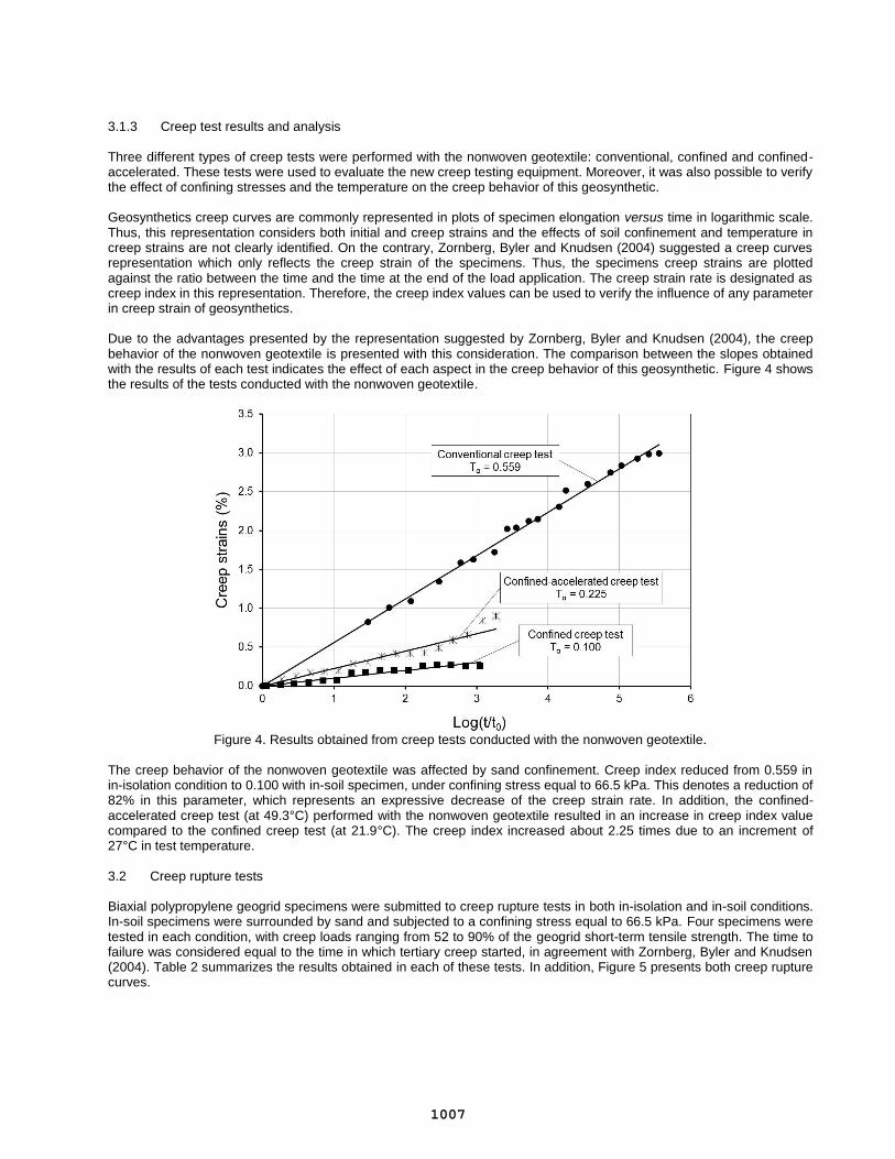
3.1.3 Creep test results and analysis Three different types of creep tests were performed with the nonwoven geotextile: conventional, confined and confined-accelerated. These tests were used to evaluate the new creep testing equipment. Moreover, it was also possible to verify the effect of confining stresses and the temperature on the creep behavior of this geosynthetic. Geosynthetics creep curves are commonly represented in plots of specimen elongation versus time in logarithmic scale. Thus, this representation considers both initial and creep strains and the effects of soil confinement and temperature in creep strains are not clearly identified. On the contrary, Zornberg, Byler and Knudsen (2004) suggested a creep curves representation which only reflects the creep strain of the specimens. Thus, the specimens creep strains are plotted against the ratio between the time and the time at the end of the load application. The creep strain rate is designated as creep index in this representation. Therefore, the creep index values can be used to verify the influence of any parameter in creep strain of geosynthetics. Due to the advantages presented by the representation suggested by Zornberg, Byler and Knudsen (2004), the creep behavior of the nonwoven geotextile is presented with this consideration. The comparison between the slopes obtained with the results of each test indicates the effect of each aspect in the creep behavior of this geosynthetic. Figure 4 shows the results of the tests conducted with the nonwoven geotextile.
Figure 4. Results obtained from creep tests conducted with the nonwoven geotextile.
The creep behavior of the nonwoven geotextile was affected by sand confinement. Creep index reduced from 0.559 in in-isolation condition to 0.100 with in-soil specimen, under confining stress equal to 66.5 kPa. This denotes a reduction of 82% in this parameter, which represents an expressive decrease of the creep strain rate. In addition, the confined-accelerated creep test (at 49.3°C) performed with the nonwoven geotextile resulted in an increase in creep index value compared to the confined creep test (at 21.9°C). The creep index increased about 2.25 times due to an increment of 27°C in test temperature. 3.2 Creep rupture tests Biaxial polypropylene geogrid specimens were submitted to creep rupture tests in both in-isolation and in-soil conditions. In-soil specimens were surrounded by sand and subjected to a confining stress equal to 66.5 kPa. Four specimens were tested in each condition, with creep loads ranging from 52 to 90% of the geogrid short-term tensile strength. The time to failure was considered equal to the time in which tertiary creep started, in agreement with Zornberg, Byler and Knudsen (2004). Table 2 summarizes the results obtained in each of these tests. In addition, Figure 5 presents both creep rupture curves.
1007
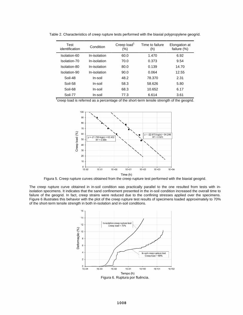
Table 2. Characteristics of creep rupture tests performed with the biaxial polypropylene geogrid.
Test identification
Condition Creep load
1
(%) Time to failure
(h) Elongation at
failure (%)
Isolation-60 In-isolation 60.0 1.470 6.92
Isolation-70 In-isolation 70.0 0.373 9.54
Isolation-80 In-isolation 80.0 0.139 14.70
Isolation-90 In-isolation 90.0 0.064 12.55
Soil-48 In-soil 48.2 78.370 2.31
Soil-58 In-soil 58.3 58.626 5.80
Soil-68 In-soil 68.3 10.652 6.17
Soil-77 In-soil 77.3 6.614 3.61 1creep load is referred as a percentage of the short-term tensile strength of the geogrid.
Figura 5. Creep rupture curves obtained from the creep rupture test performed with the biaxial geogrid.
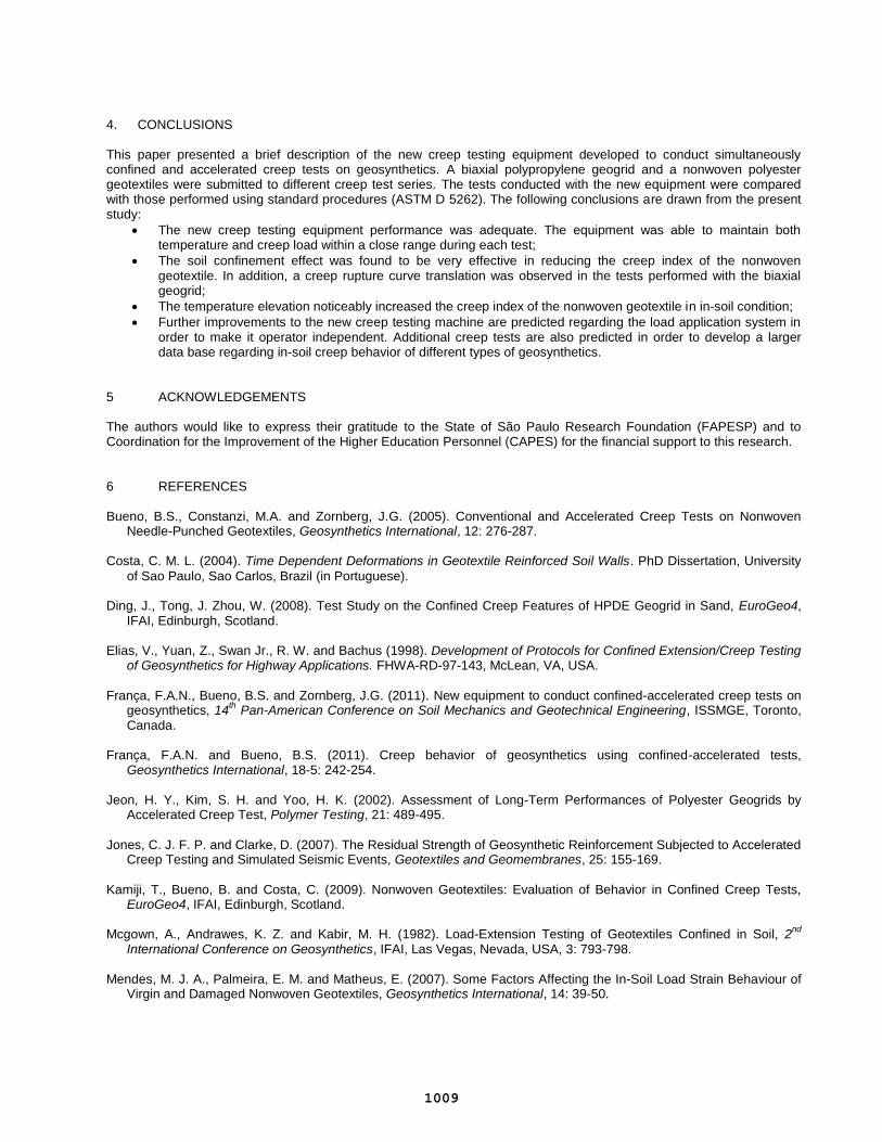
The creep rupture curve obtained in in-soil condition was practically parallel to the one resulted from tests with in-isolation specimens. It indicates that the sand confinement presented in the in-soil condition increased the overall time to failure of the geogrid. In fact, creep strains were reduced due to the confining stresses applied over the specimens. Figure 6 illustrates this behavior with the plot of the creep rupture test results of specimens loaded approximately to 70% of the short-term tensile strength in both in-isolation and in-soil conditions.
Figura 6. Ruptura por fluência.
1008
4. CONCLUSIONS This paper presented a brief description of the new creep testing equipment developed to conduct simultaneously confined and accelerated creep tests on geosynthetics. A biaxial polypropylene geogrid and a nonwoven polyester geotextiles were submitted to different creep test series. The tests conducted with the new equipment were compared with those performed using standard procedures (ASTM D 5262). The following conclusions are drawn from the present study:
The new creep testing equipment performance was adequate. The equipment was able to maintain both temperature and creep load within a close range during each test;
The soil confinement effect was found to be very effective in reducing the creep index of the nonwoven geotextile. In addition, a creep rupture curve translation was observed in the tests performed with the biaxial geogrid;
The temperature elevation noticeably increased the creep index of the nonwoven geotextile in in-soil condition;
Further improvements to the new creep testing machine are predicted regarding the load application system in order to make it operator independent. Additional creep tests are also predicted in order to develop a larger data base regarding in-soil creep behavior of different types of geosynthetics.
5 ACKNOWLEDGEMENTS The authors would like to express their gratitude to the State of São Paulo Research Foundation (FAPESP) and to Coordination for the Improvement of the Higher Education Personnel (CAPES) for the financial support to this research. 6 REFERENCES Bueno, B.S., Constanzi, M.A. and Zornberg, J.G. (2005). Conventional and Accelerated Creep Tests on Nonwoven
Needle-Punched Geotextiles, Geosynthetics International, 12: 276-287. Costa, C. M. L. (2004). Time Dependent Deformations in Geotextile Reinforced Soil Walls. PhD Dissertation, University
of Sao Paulo, Sao Carlos, Brazil (in Portuguese). Ding, J., Tong, J. Zhou, W. (2008). Test Study on the Confined Creep Features of HPDE Geogrid in Sand, EuroGeo4,
IFAI, Edinburgh, Scotland. Elias, V., Yuan, Z., Swan Jr., R. W. and Bachus (1998). Development of Protocols for Confined Extension/Creep Testing
of Geosynthetics for Highway Applications. FHWA-RD-97-143, McLean, VA, USA. França, F.A.N., Bueno, B.S. and Zornberg, J.G. (2011). New equipment to conduct confined-accelerated creep tests on
geosynthetics, 14th Pan-American Conference on Soil Mechanics and Geotechnical Engineering, ISSMGE, Toronto,
Canada. França, F.A.N. and Bueno, B.S. (2011). Creep behavior of geosynthetics using confined-accelerated tests,
Geosynthetics International, 18-5: 242-254. Jeon, H. Y., Kim, S. H. and Yoo, H. K. (2002). Assessment of Long-Term Performances of Polyester Geogrids by
Accelerated Creep Test, Polymer Testing, 21: 489-495.
Jones, C. J. F. P. and Clarke, D. (2007). The Residual Strength of Geosynthetic Reinforcement Subjected to Accelerated
Creep Testing and Simulated Seismic Events, Geotextiles and Geomembranes, 25: 155-169. Kamiji, T., Bueno, B. and Costa, C. (2009). Nonwoven Geotextiles: Evaluation of Behavior in Confined Creep Tests,
EuroGeo4, IFAI, Edinburgh, Scotland. Mcgown, A., Andrawes, K. Z. and Kabir, M. H. (1982). Load-Extension Testing of Geotextiles Confined in Soil, 2
nd
International Conference on Geosynthetics, IFAI, Las Vegas, Nevada, USA, 3: 793-798. Mendes, M. J. A., Palmeira, E. M. and Matheus, E. (2007). Some Factors Affecting the In-Soil Load Strain Behaviour of
Virgin and Damaged Nonwoven Geotextiles, Geosynthetics International, 14: 39-50.
1009

Tong, J., Gong, B. and Liu, J. (2009). An Experimental Study on the Creep Behaviour of Geogrids at Different Temperature, EuroGeo4, IFAI, Edinburgh, Scotland.
Thornton, J. S., Allen, S. R., Thomas, R. W., and Sandri, D. (1998). The Stepped Isothermal Method for Time-
Temperature Superposition and its Application to Creep Data on Polyester Yarn, 6th
International Conference on Geosynthetics, IFAI, Atlanta, Georgia, USA, 2: 699-706.
Yeo, S., Hsuan, Y. G. (2009). Evaluation of Stepped Isothermal Method Using Two Types of Geogrids, EuroGeo4, IFAI,
Edinburgh, Scotland. Zornberg, J. G., Byler, B. R. and Knudsen, J. W. (2004). Creep of Geotextiles Using Time-Temperature Superposition
Methods, Journal of Geotechnical and Geoenvironmental Engineering, 130: 1158-1168.
1010