Soil Cement Lininng Channels
13
Irrigation and Drainage Systems 5: 151-163, 1991 © 1991 Kluwer Academic Publishers. Printed in the Netherlands Soil-cement tiles for lining irrigation canals A. KHAIR 1, C. NALLURI 2 and W.M. KILKENNY 3 l Department of Irrigation Water Management, Bangladesh Agricultural University, Mymensingh, Bangladesh; 2,3 Department of Civil Engineering, University of Newcastle upon Tyne, UK Received 12 September 1990; accepted 25 February 1991 Key words: irrigation canal, soil-cement tile, compressive strength, durability, erosion due to flowing water, seepage losses Abstract. Laboratory flume test was conducted to investigate the effect of flowing water an soil- cement canal tiles. For this purpose, soil-cement tiles were constructed from different soils at various cement contents. A flume, 3 metre long and 100 mm wide, was lined with the tiles and the lined bed was subjected to flow velocities of around 2 m/s for a period of 7 days. The tiles made from coarse-textured soil (sandy loam and silt loam) aggregates of 5 mm and from fine textured soil (clay loam) aggregates of 2 mm size were found to be intact and smooth even when constructed at a cement contents lower than that needed to meet the durability requirements. Attempts were also made to measure seepage losses of soil-cement tile linings. A channel section of approximately 1 metre length with a side slope of 1:1 was constructed in the laboratory with the tiles and seepage losses measured by the ponding method were found to be in the range of 0.00123-0.00343 m3/mZ/day. The results clearly suggest that soil-cement tiles (irrespective of type of soil) made with 2 mm or less size of soil aggregates are erosion resistant and due to very little or negligible rates of seepage losses, the soil-cement tile lining of irrigation canals is expected to be very promising especially in the areas where irrigation water is costly. Introduction Garg & Chawla (1970) reported that in unlined irrigation canal systems seepage losses are so high that, in several systems, the quantity of water delivered to the fields may be less than 50% of that drawn in the head. According to the FAO (1971) the seepage losses per 1.6 km length of an irrigation canal can be as high as 20O7o of its conveyance capacity. Ahuja & Mehndiratta (1967) report- ed 18 to 50070 of water losses in irrigation canals in India. Saran et al. (1967) stated losses of around 47% in irrigation canals in India, 33 to 60% in USA and 25 to 60% in Mexico. According to Jenkins (1981) the canal water losses in Bangladesh were about 50% in a 300 m long, 57 litres/s size earth channel. Besides such a heavy loss of valuable irrigation water, excess seepage contrib- utes to water logging of farm lands, salt and alkali concentrations in soils
-
Upload
sccmvtrnet -
Category
Documents
-
view
77 -
download
0
Transcript of Soil Cement Lininng Channels

Irrigation and Drainage Systems 5: 151-163, 1991 © 1991 Kluwer Academic Publishers. Printed in the Netherlands
Soil-cement tiles for lining irrigation canals
A. K H A I R 1, C. N A L L U R I 2 and W . M . K I L K E N N Y 3
l Department of Irrigation Water Management, Bangladesh Agricultural University, Mymensingh, Bangladesh; 2,3 Department of Civil Engineering, University of Newcastle upon Tyne, UK
Received 12 September 1990; accepted 25 February 1991
Key words: irrigation canal, soil-cement tile, compressive strength, durability, erosion due to flowing water, seepage losses
Abstract. Laboratory flume test was conducted to investigate the effect of flowing water an soil- cement canal tiles. For this purpose, soil-cement tiles were constructed from different soils at various cement contents. A flume, 3 metre long and 100 mm wide, was lined with the tiles and the lined bed was subjected to flow velocities of around 2 m/s for a period of 7 days. The tiles made from coarse-textured soil (sandy loam and silt loam) aggregates of 5 mm and from fine textured soil (clay loam) aggregates of 2 mm size were found to be intact and smooth even when constructed at a cement contents lower than that needed to meet the durability requirements.
Attempts were also made to measure seepage losses of soil-cement tile linings. A channel section of approximately 1 metre length with a side slope of 1:1 was constructed in the laboratory with the tiles and seepage losses measured by the ponding method were found to be in the range of 0.00123-0.00343 m3/mZ/day.
The results clearly suggest that soil-cement tiles (irrespective of type of soil) made with 2 mm or less size of soil aggregates are erosion resistant and due to very little or negligible rates of seepage losses, the soil-cement tile lining of irrigation canals is expected to be very promising especially in the areas where irrigation water is costly.
Introduct ion
G a r g & C h a w l a (1970) r e p o r t e d tha t in u n l i n e d i r r i g a t i o n cana l sys tems seepage
losses a re so h igh tha t , in severa l sys tems , the q u a n t i t y o f wa t e r de l ive red to
the f ie lds m a y be less t h a n 5 0 % o f tha t d r a w n in the head . A c c o r d i n g to the
F A O (1971) the seepage losses pe r 1.6 k m l eng th o f an i r r i ga t i on cana l can be
as h igh as 20O7o o f its c o n v e y a n c e capac i ty . A h u j a & M e h n d i r a t t a (1967) r epo r t -
ed 18 to 50070 o f wa t e r losses in i r r i g a t i o n cana l s in Ind ia . S a r a n et al. (1967)
s ta ted losses o f a r o u n d 4 7 % in i r r i g a t i o n cana l s in Ind ia , 33 to 6 0 % in U S A
a n d 25 to 6 0 % in M e x i c o . A c c o r d i n g to J e n k i n s (1981) t he cana l w a t e r losses
in B a n g l a d e s h were a b o u t 5 0 % in a 300 m long , 57 l i t r e s / s size ea r th channe l .
Besides such a h e a v y loss o f v a l u a b l e i r r i g a t i o n wa te r , excess s eepage con t r i b -
utes to wa t e r l o g g i n g o f f a r m lands , salt and a lkal i c o n c e n t r a t i o n s in soils

152
resulting in costly maintenance roads and drainage systems and reduction in total agricultural output. USBR (1963) and Sarker (1967) stated that in many irrigation projects this led to very uneconomical irrigated agriculture and at times to abandoning of the entire project. Canal lining is considered to be most effective in reducing water losses and practical linings should be near impervi- ous, inexpensive, strong and durable. Hard surface linings of reinforced and plain concrete, sand-cement blocks, stone and brick masonry and asphalt con- crete meet many of these requirements but are the most expensive. Although brick and stone masonry linings are commonly used in many developing coun- tries as low cost materials for lining main canals, branches and distributories, the cost are prohibitive for small channels.
In many countries low cost materials such as impermeable earth, bentonite, vegetative covering, polythene sheets, asphalt mats, etc. are being used as low cost linings to minimise water losses in irrigation canals at varying degrees of success. Although these linings have been characterized as low cost techniques, their durability is very uncertain. While initial costs may be low, maintenance costs could be high. These linings may be highly susceptible to damages by bur- rowing animals, weed puncture, rain and flowing water. Besides many sub- stances also have been used to stabilize or seal canal and lateral subgrade materials. These include specially treated resins, chemicals such as sodium sili- cate in combination with sodium and clacium chloride, a commercial resin ce- ment, lime, portland cement, asphalts, petrochemicals, and others including combinations of the above. Corps of Engineers (1956) described several promising chemical soil stabilizers, but attached certain limitations in their use as well as their unfavourable economics and concluded that the best way for- ward was re-evaluation of stabilization with conventional materials, i.e. ce- ment or asphalt. USBR (1963) reported that soil-resins linings often deteriorate badly shortly after construction and chemicals are not adaptable to canal use because of the high cost as well as their poor resistance to wetting-drying or freezing-thawing cycles. Kinori (1970) stated that asphalt concrete lining is very costly and can be used only for large channels. Asphaltic oil linings deteriorate rapidly when exposed to rain and sunshine. There is a tendency for asphalt to separate from the aggregate when exposed to water over a long period causing rapid disintegration. Asphalt mats are usually damaged by weed puncture. Plastic film and synthetic rubber membrane linings are usually damaged by weed growth.
Soil is the oldest, cheapest and probably the most use of construction ma- terials. However, there are limitations to the use of natural soils due to its lack of strength and its valnerability to moisture content changes and the erosive ef- fects of external agencies. Soil stabilization is a technique aimed at increasing or maintaining the stability of the soil mass.
Lambe & Moh (1957) describe that portland cement is one of the most

153
common and successful stabilizer for soils. When cement is used as a soil stabilizing agent to improve its strength and its resistance to change, it is termed
soil-cement. Portland Cement Association (1984) has described that engineers and contractors have been using soil-cement to pave roads, streets, airports and parking areas and its performance has been outstanding. The Portland Cement Association also stated that soil-cements' low-cost, ease of construction utiliza- tion of local or inplace soil make such application economical practical and en- vironmentally attractive.
The extensive use of soil-cement for road pavements and runways has led to the experimental use of this material for canal and ditch lining. There are two types of soil-cement lining: compacted (standard) and plastic. Standard soil- cement lining has proved to be unsuccessful mainly due to lack of optimum compaction. The portland cement Association (1956) reported that a higher percentage of cement is always needed to make durable plastic soil-cement lining and also is susceptible to damages due shrinkage cracks. However, the outstanding service record of soil-cement in other fields indicates that soil- cement could be a promising low cost lining if it can be properly placed and compacted to obtain maximum density without difficulty.
In the circumstances, Khair (1988) showed that soil-cement tiles of 20 to 25 mm thickness if constructed with a cement contents to satisfy the criteria as mentioned below is durable in the irrigation field to withstand the stresses in- duced by the sun and rain:
- Soil-cement specimens should not suffer a loss in strength more than 10% after 7-day immersion test (British durability test).
- Soil-cement specimens should give a minimum wet unconfined compressive strength of 1.724 M N / m 2 after 7-day curing in the humidity cabinet.
Khair also showed that such type of lining with a life expectancy of 8 years is economically superior to all other linings (plastic soil-cement, asphalt mat, precast concrete section, brick lining, clay plastering and unlined section) cur- rently being used in Bangladesh.
The merit of a satisfactory lining not only lies in its ability to resist destruc- tive forces of weathering (sun and rain) but it must be resistant to erosion caused by flowing water as well as impermeable engough to reduce seepage losses. Hence, a detailed experimental programme was undertaken at the University of Newcastle upon Tyne, UK to investigate the resistant of soil- cement tile to flowing water and as well as to assess its merit in reducing seepage losses.

154
Experimental investigations
Selection o f soils
Three different types of soil (clay loam, sandy loam and silt loam) were collect-
ed for this investigation whose physical and chemical properties are shown in
Table 1.
The results in Table 1 show that soils collected for the present investigation
are almost suitable for cement stabilization. The soils for this investigation were not selected merely on the basis of the suitability according to the criteria
set by previous investigators for the construction of road pavements and rural
houses, rather the soils were selected randomly with a view to establishing
criteria for the construction of soil-cement tiles for lining small irrigation
canals.
Preparation o f soil-cement tiles
The Brepak (Developed by the Building Research Establishment, UK) block
making machine was used for the manufacture of soil-cement tiles. The press
consists of a moulding area of fixed size which, together with the structural
frame, forms an integral unit of an all steel construction. Access to the mould
area is via a top cover plate, pivoting about a corner mounted located pin. The
press is fittted with a lever arm extension and mechanical linkage which pro-
vides a means of locking the top cover plate onto the mould and also allows
for initial compaction of the block material within the mould area. Once the lever arm and cover plate are secured the compaction pressure is then applied
using a hand operated hydraulic pump. This manually operated machine is
especially suitable for rural areas where there is no power supply. The standard
size of building block as produced by the Brepak press is 290 x 140 x 100 mm.
The press is a constant volume type and ram moves a fixed distance so that al-
ways a standard block size with a thickness of 100 mm is produced. Therefore,
Table 1. Physical and chemical properties of soil samples.
Soil type Liquid Plastic Plasticity Organic Sulphate limit limit index content content (%) (%) (070) (%) (%)
Clay loam 33 20 13 1.07 0.056
Sandy loam 27 non-plastic - 2.27 0.047
Silt loam 35 non-plastic - 1.69 0.052

155
to produce tiles of varying thickness, steel separator plates were introduced
into the moulding cavity of the press. In order to construct tiles of 25 mm thick-
ness, two separator steel plates measuring 289 × 138 × 12.5 mm were used. The mass of cement treated soil mixture required to make a tile of the size 290 × 140 × 25 mm was calculated f rom the following relationships:
m = (1015 + 10.15 w) P~ (1)
where, m = mass of cement-treated soil mixture, g
w = opt imum moisture content of the mix in per cent obtained at a compact ion pressure of 10 M N / m 2
Pd = maximum density of dry soil plus cement in M g / m 3 achieved at a compaction pressure of 10 M N / m 2
As the maximum density of soil-cement mixture varies only slightly (Port- land Cement Association 1956) with cement content the result of the moisture
density (Table 2) relationship obtained at 6% cement content at a compaction pressure of 10 M N / m 2 were used for moulding the tile specimens at different cement (ordinary Port land Cement) contents.
The measured amount of stabilized soil needed to produce a tile of 25 mm thickness as calculated using Eq. 1 was put into the mould, then a separator
plate, a further amount of mix for another tile followed by the second plate and finally another amount of mix for the third tile. Then the top cover plate of the press was moved to its closed position and the main hand lever was re- moved through an arc to initially compact the soil. Next, the flow control valve
on the hand hydraulic pump was closed and the handle was operated until a pressure of 8,000 psi, approximately 10 M N / m 2 effective pressure on the tile, was indicated. Then the flow control valve was released and the lever arm was lifted from its horizontal position and reversed to its original start position. By
applying downward force on the lever arm, the newly pressed tiles were de-
moulded f rom the mould box. In one operation of the machine, 3 tiles of size 290 × 140 × 25 mm are produced and a man is capable of producing 150 tiles per day. Cost incurred to produce such type of 1,000 tiles is approximately US $ 5.0 only. After construction, the tiles were wrapped in polythene bags and
Table 2. Opt imum moisture contents and max i mum densities of soil-cement mixture.
Soil type Aggregates Maximum dry
density (Mg/m 3) Opt imum moisture
content (%)
Clay loam Soil + 6% cement 1.984 12.45
Sandy loam Soil + 6°70 cement 1.886 12.40
Silt loam Soil + 6% cement 1.630 15.00

156
4 .0 0 0 C L A Y - L O A M SOIL u~ ~. A SANDY-LOAM
(~1~ E Z
- 3 . 0 "r I--. 0 Z L~
F-' -4 -M -/Tn-2
S 1.0
C3
Z
Z 0 U Z 0.0 , I I I I I I I
D 0.0 2.0 4.0 6,0 g,o 12.0
CEMENT CONTENT ( % ) , C
Fig. 1. E f f e c t o f cement content on strength of soil-cement specimens after 7 days curing and 24
hour immersion.
the bags were sealed to prevent any loss of moisture and to reduce carbonation effect. The sealed bags were then stored in a humidity cabinet for 28 days curing.
Durability and compressive strength tests
Tests were conducted on soil-cement cylindrical specimens in accordance with Britsh Standard (BS1924. 1975) to establish the durability requirements with various cement contents in the mix. Figure 1 shows the relationship between the cement content and 7-day wet unconfined compressive strengths (1.724 M N / m 2 and 1.4 M N / m 2 are the c o m m o n minima for soil-cement used for road pavements and for building blocks, respectively) o f the specimens whereas Fig. 2 shows their resistance to 7-day immersion.
Figures 1 and 2 suggest that the criteria of minimum unconfined compressive strength of 1.724 M N / m 2 and 7-day immersion test (not to suffer a loss in strength by more than 10%) are met with the cement contents of 8%, 11 °70 and 10% for clayey, sandy and silty loams, respectively.

157
rio
Io0
ff 9o
0
I .d
- 7 0
C3 , 60 © i---
50 U Z ~ 4o
I .d
a: 3 0
!," ~ SILT -LOAM.
0 0 CLAY-LOAM
A z,. S A N D Y - L O ~
/ !
! !
/ I
I I I I I t I I
2.0 4.0 6-0 B.0 I0.0 t2.0 CEMENT CONTENT ( ~ )
20 0.0 14.0 16,0
Fig. 2. Resis tance to immers ion of soi l -cement specimen at d i f ferent cement contents .
Erosion and seepage tests in f lumes
Tiles of 25 m m thick made (using Brepak machine) from various soils at dif- ferent cement contents with opt imum moisture contents and densities were
used for erosion tests. Curing period has significant effect on strength of soil- cement specimens. Khair (1988) showed that the strength at 7-day are approxi-
mately 60 to 70°7o of those at 28 days. Hence 28 days curing period was consi- dered to be appropriate to obtain a quality of soil-cement tile. Therefore, after 28 days curing in the humidity cabinet, the tiles were cut to size to be accommo- dated within a laboratory flume of 3 m long and 100 m m wide. The tiles were
fixed on to the bed of the flume using water-proof glue and the joints between the tiles were filled with cement treated soil-mixtures. The flow rates supplied to the flume were measured by an on-line orifice-meter introduced in the supply pipe line. Knowing the water depth (hence the area of flow) the flow velocities were computed. The lined bed of the flume was immersed under water for a period of 7-day to allow the expansive clays, organic matter, sulphate and other detrimental constituents to be fully active. The bed was subjected to flow veloc- ities of around 2 m/Is for a period of further 7 days at a rate of 6 hours per day.

158
Table 3. Erosion (due to flowing water) tests results.
Soil type Soil aggregate Cement Bed Suspended Visual passing sieve content load load observations size (mm) % gm/hr gm/hr
Clay loam 5.00 6.00 Negligible Negligible Surface roughening all unpulverised clay particles washed away
Clay loam 5.00 8 . 0 0 Negligible Negligible -do- Clay loam 3.35 8 . 0 0 Negligible Negligible -do- Clay loam 2.80 8 . 0 0 Negligible Negligible Surface almost
smooth, little roughening
Clay loam 2.00 8.00 0 0 Smooth surface, no roughening
Clay loam 2.00 6.00 0 0 -do- Sandy loam 5.00 8.00 0 0 -do- Silt loam 5.00 8.00 0 0 -do-
Dur ing this test per iod the tile surface was visual ly observed for any eros ion
and a t t empts were made to measure the e roded mater ia l s quant i ta t ive ly by in-
stal l ing a bed load t rap at the d o w n s t r e a m end o f f lume. Also water samples
were t aken by a special ly adop t ed pipet te at regular intervals and ana lysed for
the t races o f suspended load, if any, caused by eros ion. The eros ion test results
are summar i sed in Table 3.
Seepage tests were conduc ted in a l a b o r a t o r y channel special ly cons t ruc ted
and lined with soi l -cement tiles (af ter 28 days curing in the humid i ty cabinet
and the jo in t s being fi l led with bo th the plast ic soi l -cement and cement
mor ta r s ) .
The tiles were o f 25 m m thick and made o f clayey, sandy an silty loams with
.¢v IN FILL - - IN CuT tic 350 ORIGINAL GROUND SURFACE
":" -<--=~ ~ / " ~ ' : ~ 190T mm
/
Fig. 3.0.056 cumec canal to be lined with soil-cement tiles.
159
350 J~f--IN F I L L + IN CUT k V o Rqrcq N'a-C" G ~ 0 " ~ 7 7 i suRfAcE T--
..... - - - - = mm
~ORIGINAL GROUND SURFACE / I ~ 2 2 1 2 2 ~ o G ~ M ~A N ~ M [ N T
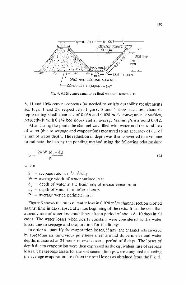
Fig. 4. 0.028 cumec canal to be lined with soil-cement tiles.
8, 11 and 10% cement contents (as needed to satisfy durability requirements
see Figs. 1 and 2), respectively. Figures 3 and 4 show such test channels representing small channels of 0.056 and 0.028 m3/s conveyance capacities,
respectively with 0.1% bed slopes and an average Manning's n around 0.012.
After curing the joints the channel was filled with water and the total loss of water (due to seepage and evaporation) measured to an accuracy of 0.1 of
a mm of water depth. The reduction in depth was then converted to a volume
to estimate the loss by the ponding method using the following relationship:
24 W (d 1 - d2) S = (2)
Pt
where
S = seepage rate in m3/m2/day
W = average width of water surface in m
d 1 = depth of water at the beginning of measurement in m
d 2 = depth of water in m after t hours
P = average wetted perimeter in m
Figure 5 shows the rates of water loss in 0.028 m3/s channel section plotted
against time in days lapsed after the beginning of the tests. It can be seen that
a steady rate of water loss establishes after a period of about 8 - 1 0 days in all
cases. The water losses when nearly constant were considered as the water
losses due to seepage and evaporation for tile linings.
In order to quantify the evaporation losses, if any, the channel was covered by spreading an impervious polythene sheet around its perimeter and water
depths measured at 24 hours intervals over a period of 8 days. The losses of
depth due to evaporation were then expressed as the equivalent rate of seepage
losses. The seepage losses for the soil-cement linings were computed deducting
the average evaporation loss from the total losses as obtained from the Fig. 5.

160
I 0 0
:>-
< 9.0 cl
~ 8.0
E im 7.0
6 .0 b J ~D <
5.0
O 4.0 }.._
~ 3 , 0
LO
m 2.0
O -3
cr I.O klJ p - <
~: o o 0
A A SILT-LOAM SOIL
O O S A N D Y - LOAM SOIL
H C L A Y - L O A M SOIL
A A ^
[, I I I I i I i
2. 4 6 8 I0 12 14 16
TIME IN DAYS
Fig. 5, Rate of water losses in a smaller canal section lined with soil-cement tiles made from dif-
ferent type of soils.
Results and discussion
Tile surface, made from clay loam soil aggregate of above 2 mm size, were roughnened due to the washing away of unpulverised clay particles when sub- jected to flow (bed shear stress) velocities of around 2 m/s . The soil loss due to erosion in these cases was so small that the usual methods failed to detect it. The tiles made from sandy loam soil aggregates of 5 mm and above and from clayey soil aggregates o f 2 mm and less in size were found to be intact and smooth even after 7 days flume operation at velocities around 2 m/s . Tiles made from clay loam soil need, 8°70 cement content to meet the standard dura- bility criteria (Figs 1 and 2) but were found undurable to flowing water when constructed with soil aggregates larger than 2 mm size. On the otherhand, tiles made from silt and sandy loam soils were found unaffected to flowing water even when constructed at a cement contents lower than those needed to meet the standard durability criteria.

161
The losses (seepage + evaporation) estimated from Fig. 5 are 0.0018, 0.003 and 0.004 m3/m2/day for soil-cement tiles made from clay loam, sandy loam and silt loam soils, respectively. In the field condition, evaporation losses are generally neglected but the measurement of evaporation may be necessary when evaporation losses are significant in comparison to seepage losses. In this study, the average computed evaporation loss was 0.000572 m3/m2/day and was considered to be significant in comparison to seepage losses and hence seepage losses for the linings were computed by deducting this evaporation loss. The seepage losses thus obtained were 0.00123, 0.00243 and 0.00343 m3/m2/day for the tiles made from clay loam, sandy loam and silt loam soils respectively. These losses are negligible in comparison to even sophisticated concrete lining for which the average seepage toss is about 0.084 m3/m2/day.
In the laboratory, under controlled conditions the losses ranged from 0.00123-0.00343 m3/m2/day, but even considering the field conditions (where proper controlled criteria may not be applicable) the seepage losses through the soil-cement tile lining may not exceed about 0.005-0.01 m3/ mZ/day.
Khair (1988) stated that soil-cement tiles are not structurally strong enough to resist external forces such as walking animals, earth or hydrostatic pressures. Therefore, the channel for lining with soil-cement tiles should be constructed in such a way so that the bottom and sides of the channel should neither be sub- jected to uplift or horizontal pressures of earth and water. Earth pressure can be avoided if the bank of the canal is made flatter than the angle of the repose of the bank material. When the bottom of a channel is above the groundwater surface, the channel will not be subjected to uplift pressure due to water. A compacted, stable subgrade is a pre-requisite for soil-cement tile lining to avoid damages due to walking animals. Construction of soil-cement canal tiles to resist damages due to walking animals would be highly uneconomical and therefore, it is justified to accept periodic maintenance than to have a fool- proof, stong but costly lining.
Soil-cement tile linings may also fail due to adverse subgrade conditions such as loss of support through piping action or heave of expansive clays. Therefore, either lining should be avoided on expansive clays or such clays should be replaced by non-expansive soils. Failure by cracking of the lining in many cases can be attributed to the poor preparation of subgrades. Before, placing tiles, the subgrade should be prepared, dressed and compacted to a level according to the required cross-section of the canal. After the preparation of the subgrade in the shape of the channel, it should be wetted before placing the tiles in order to prevent the withdrawal of moisture from freshly placed plastic soil-cement mixture between the joints. The tiles also should be fully saturated, at least 24 hours before laying.
For soil-cement lining, there will be a natural safeguard against cracking due

162
to closely spaced joints as in brick linings. As the soil-cement tiles will be satu-
rated before laying, there will be little or no probabil i ty o f damage o f the lining
due to expansion o f the tiles after absorpat ion. However , during the drying period, contract ion o f tiles may result in cracks in the joints. Therefore, it is
suggested to fill the joints with bond preventing materials. It is suggested that
approximately 7.5 mm joints between the tiles should be provided. According
to Khair (1980), the joints may be filled with bo th plastic soil-cement mixtures
and cement mor ta r (1:3). Plastic soil-cement should be applied with an al- lowance so that at least 5.0 mm cement mor ta r could be applied over the plastic
mixtures after its curing. Besides, any bond preventing materials such as
asphaltic materials may be used as a joint filler if found resistant to weather,
insects, chemical at tack and weeds.
Conclusions
Soil-cement tiles are expected to be durable to flowing (at a round 2 m/sec . )
water if they are constructed to meet the s tandard durabili ty criteria (7-day
strength and British durabil i ty test) except those made f rom plastic soil; plastic
or non-granular soils should be pulverized to pass tho rough 2 m m sieve to be
resistant against erosion due to flowing water.
The seepage losses in channels lined with soil-cement tiles is not expected to
be more than 0 .00123-0 .00343 m3/m2/day ; this is very small even in compari-
son with concrete lining. The soil-cement lining thus seems to be attractive and very promising in areas
where irrigation water is costly.
References
Ahuja P.R. & Mehndiratta K.R. 1967. Canal lining - a review. Central Board of Irrigation and Power, Symposium on-Canal Lining, Publication No. 82. New Delhi, India.
BS1924. 1975. Methods of Tests for Stabilised Soils. British Standards Institution, UDC 624 131.3: 631.4, Gr. 9 London.
Corps of Engineers, U.S. Army. 1956. Summary Reviews of Soil Stabilization Process. ReportNo. 3. Soil-Cement, Miscellaneous Paper No. 3-122 (pp 1-27).
FAO. 1971. Irrigation canal lining. Irrigation and Drainage Paper No. 2, Land and Water De- velopment Division. Food and Agricultural Organization, Rome.
Jenkins D. 1981. Irrigation and water distribution systems for tubewells and low-lift pumps in Bangladesh. USAID, CARE-Bangladesh.
Khair A. 1988. Soil-cement tiles for lining small irrigation canals in developing countries. Ph.D. thesis, University of Newcastle upon Tyne, UK.
Kinori B.Z. 1970. Manual of Surface Drainage Engineering, Vol. I. Elsevier Publishing Company, Amsterdam-London-New York.

163
Lambe T.W. & Moh Z. 1957. Improvement of strength of soil-cement with additives. Highway Research Board Bull 183: 38-47.
Portland Cement Association. 1956. Soil-Cement Laboratory Handbook. 33, West Grand Avenue, Chicago 10, Illinois, USA.
Portland Cement Association. t984. Soil-Cement for Facing Slope and Lining Channels, Reser- voirs, and Lagoons. Soil-Cement, 5420 Old Orchard Road, Skokie, Illinois 60077-5321, USA.
Saran R., Dwivedi N.K. & Sangal S.P. 1967. Lining water Courses. Central Board of Irrigation and Power, Publication No. 82, New Delhi, India.
Sarker S.N. 1967. The Problem of Canal Lining. Central Board of Irrigation and Power, Publica- tion No. 82, New Delhi, India.
USBR. 1963. Linings for Irrigation Canals. United States Department of Interior Bureau of Recla- mation, USBR, Fort Collins.