Software Requirements Specification (SRS) Generic Ethernet...
27
Software Requirements Specification (SRS) Generic Ethernet Gateway Project (GWAY) Authors: Keyur Patel, Ben Blaut, Tony Cooke, Luan Tran Customer: Mr. Anthony Torre, Chrysler Group LLC Instructor: Dr. Betty Cheng, Ph.D 1 Introduction Every year, new automobile models are released with new and innovative features that require an everincreasing amount of software. These embedded systems frequently communicate with each other, and oftentimes they do so through a gateway. This document describes the Generic Ethernet Gateway (GWAY). The GWAY is an onboard communications infrastructure that facilitates communication among the varied embedded systems within the vehicle and with external connections, such as diagnostic and reprogramming workstations. This document begins by outlining the scope of the product and its purpose, then clarifies terminology. The document also gives an overview of the system, including product function characteristics and constraints. Additionally, an enumerated list of specific requirements divided into subsections are provided. To further clarify the requirements, visual models of the structure and behavior of the system are given. These models help provide a clearer understanding the system. Likewise, a description of how to run the prototype scenarios are contained in this document to visually capture observable behavior of the system. Lastly, a list of references and a point of contact will be included. 1.1 Purpose The purpose of this document is to describe the specific requirements for the GWAY system. This document is intended to provide an unambiguous, concise, and complete list of requirements to help design the Ethernet Gateway. This document will include constraints and show how to use the system. The document is primarily intended for Mr. Anthony Torre of Chrysler Group LLC and any other personnel that will work directly with this system, as well as any stakeholders of the system. 1.2 Scope The Generic Ethernet Gateway is a control system designed to allow communication between various embedded systems. More precisely, these messages can originate from CAN (Controller Area Network) ports or Ethernet ports, thus the gateway may need to convert protocols. Therefore the main goal of the system relies on facilitation of messages from one embedded system to another. Additionally, the gateway can conduct diagnostic tests on the system and reprogram the firmware of the gateway or any other connected system as needed. This allows for one point of entry or in this case, one port on the AVB (Audio Video Bridging)
-
Upload
trinhtuong -
Category
Documents
-
view
231 -
download
3
Transcript of Software Requirements Specification (SRS) Generic Ethernet...

Software Requirements Specification (SRS)Generic Ethernet Gateway Project (GWAY)
Authors: Keyur Patel, Ben Blaut, Tony Cooke, Luan TranCustomer: Mr. Anthony Torre, Chrysler Group LLCInstructor: Dr. Betty Cheng, Ph.D
1 IntroductionEvery year, new automobile models are released with new and innovative features that requirean everincreasing amount of software. These embedded systems frequently communicate witheach other, and oftentimes they do so through a gateway. This document describes the GenericEthernet Gateway (GWAY). The GWAY is an onboard communications infrastructure thatfacilitates communication among the varied embedded systems within the vehicle and withexternal connections, such as diagnostic and reprogramming workstations.
This document begins by outlining the scope of the product and its purpose, then clarifiesterminology. The document also gives an overview of the system, including product functioncharacteristics and constraints. Additionally, an enumerated list of specific requirements dividedinto subsections are provided. To further clarify the requirements, visual models of the structureand behavior of the system are given. These models help provide a clearer understanding thesystem. Likewise, a description of how to run the prototype scenarios are contained in thisdocument to visually capture observable behavior of the system. Lastly, a list of references anda point of contact will be included.
1.1 PurposeThe purpose of this document is to describe the specific requirements for the GWAY system.This document is intended to provide an unambiguous, concise, and complete list ofrequirements to help design the Ethernet Gateway. This document will include constraints andshow how to use the system. The document is primarily intended for Mr. Anthony Torre ofChrysler Group LLC and any other personnel that will work directly with this system, as well asany stakeholders of the system.
1.2 ScopeThe Generic Ethernet Gateway is a control system designed to allow communication betweenvarious embedded systems. More precisely, these messages can originate from CAN(Controller Area Network) ports or Ethernet ports, thus the gateway may need to convertprotocols. Therefore the main goal of the system relies on facilitation of messages from oneembedded system to another. Additionally, the gateway can conduct diagnostic tests on thesystem and reprogram the firmware of the gateway or any other connected system as needed.This allows for one point of entry or in this case, one port on the AVB (Audio Video Bridging)

switch if firmware upgrades are needed.
Another goal of the system deals with security. Message packets inside the system must beencrypted to make sure an unauthorized person cannot hijack information on the gateway suchas fault codes.
While the system shall perform various tasks listed above, there are a number tasks thegateway should not perform. First, the gateway cannot alter any of the data packets that itreceives. The packets must be forwarded to the appropriate port number while keeping its dataintact, however it may modify packet headers in case protocol conversions are required. Also,the system may not forward any unencrypted packets; all packets must be encrypted.
The use of a gateway comes with many benefits. One of the main benefits of a gateway systemis that it greatly reduces the number of physical wires needed inside an application system. Thisis made possible by not requiring the many different systems to be interconnected with eachother, but rather connected to a single gateway (Figure 1). As a result, Electronic Control Units(ECU) can have a single CAN interface rather than having digital inputs to every device in thesystem. This approach greatly reduces the complexity of electronic systems that, in turn, helpsto reduce the cost and even the weight of the application domain. Moreover, new embeddedsystems can be easily connected to all other systems by simply connecting to a CAN bus.Additionally, the gateway can shut down ports if information coming from the ports seemsirregular. For example, if a fault sensor keeps sending errorfilled messages, the gateway canshut down the port to prevent unwanted noise from coming into the gateway.
Figure 1: Benefits of use CAN networks. Source:[5]
There are various application domains for this system. This system can be used in aerospace,automotive industry, and even the military. Inside these entirely different application domains, thegateway is an embedded system that helps various other embedded systems communicatewith each other. For example, inside an automobile or even an airplane, the sensor that senses

cabin temperature can send a message to the air conditioning unit to turn on the fan.
1.3 Definitions, acronyms, and abbreviationsThis section contains definitions of the acronyms, abbreviations, and specific terminology usedin this document.
AUTOSAR A document that contains standards for automotive electricalsystems.
AVB Audio Video Bridging. Set of standard developed by IEEE thatallows the transmission of audio and visual streams to besynchronized with each other with minimal latency.
Bridge Connects networks with the same protocol (e.g CAN) andforwards messages from one network to another.
Bus A medium that transfers data between different systems.
CAN Controller Area Network. A serial bus network that connectsmultiple devices such as sensors and systems inside anautomobile together. Speed of data transfer upto 1 mbps.
CAN Bus CAN Bus only transmits data on a CAN wire.
Database A collection of data.
Denial of Service(DOS)
Occurs when information is coming in too fast into the gateway.This overloads the gateway that does not allow other systems touse the service of the gateway.
Ethernet A wire that supports data transfer rates up to 100 mbps. Used inautomobile to handle infotainment data and any other servicethat requires a large amounts of bandwidth.
Ethernet Bus Ethernet Bus only transmits data on a Ethernet wire.
ECU Electronic Control Unit. A general term given to an embeddedsystem that controls and receives input from multiple systems.
Gateway Interfaces with networks that use different protocols (e.g. CANand Ethernet). It interconnects different networks by performingrequired protocol conversions.

GWAY Generic Ethernet Gateway Project. The system beingdescribed in this SRS document.
IP Internet Protocol. Each device has a unique IP address to allowfor referencing.
IO Input Ouput. Represents anything that might be a input or outputof the system.
MBPS Megabitspersecond. A rate of how fast data is transferred.
Noise Unwanted information coming into the gateway from a port.
Packet Contains chunks of data from a message. Multiple packets maybe needed to transfer one piece of information. Information onthe system data is in packets.
Port A specific location on the gateway that allows systems toconnect to the gateway. Each port has a unique IP address toallow for referencing.
RJ45 Another word for Ethernet cable.
SRS Software Requirement Specification. A document that containsdetailed information about the requirements of a system, itsconstraints and the goals. Required for being productdevelopment.
SQL SQL is a programming language used to manage databases.
Sub09 A standard 9pin electrical connector.
UML Unified modeling language. A multiple purpose modelinglanguage used to model requirements.
VLAN A technology that allows layer two networks to be virtuallysegmented into separate broadcast domains.

1.4 OrganizationThe rest of the document is broken down into six sections.
Section 2 contains the overall description. In this section, the document will provide informationabout the system functions. Also included in this section is a description of the constraintsneeded for safety, as well as any assumptions made in the user characteristics anddependencies.
Section 3 has a hierarchical enumerated list of the requirements the system must fulfill.
Section 4 contains various models that specify the bridge between application domain andmachine domain. In this section, UML diagrams and their respective detailed explanations areused to visualize and demonstrate the expected behavior of the system.
Section 5 gives an overview of the prototype, describes how to access it and run it, as well asexamples of sample scenarios.
Section 6 gives a list of all the references used to compile this document.
Section 7 gives a point of contact if more information is required.
2 Overall DescriptionThis section serves to summarize the product, its major functions, characteristics,characteristics of its users, constraints, assumptions, and items that are outside of the scope ofthis project.
2.1 Product PerspectiveThe gateway can be used in multiple settings, including industrial, automotive, aerospace, andmilitary applications. Wherever CANs are in use, the gateway facilitates interCANcommunication and communications from nonCAN sources through Ethernet.
The gateway itself is a component connecting multiple networks. The gateway connects to up tosix CANs and one AVB ethernet connection. The AVB ethernet connection may be a singledevice such as a diagnostic computer, or an AVB switch which aggregates multiple connectionsto the gateway. Gateway to CAN connections will use the DSub 9 terminator, and gateway toAVB Ethernet will use RJ45 connections. At installation time, CAN ports must be enabled ordisabled as needed per the application. The operating system environment for the gateway willinclude AUTOSAR [5], 1 MB of memory, and the most costeffective commercial CPU available.
Figure 2.1 shows a common configuration of the gateway.

Figure 2.1: A sample block diagram of the gateway and connected components.
2.2 Product FunctionsThe primary function of the gateway is to perform message passing among the connected CANsand any device(s) connected to the ethernet port. For example, messages originating from “CAN1” in Figure 2.1 may be routed to “CAN 2” or to any device connected to the AVB switch. Thereverse is also true; any device connected to the AVB switch may send messages to nodes onCANs connected to the gateway.
The ethernet port will also facilitate upgrading the firmware of the gateway device or individualcontrollers on the CAN networks and performing diagnostics over IP. For example, in Figure 2.1,“AVB Device 1” may be a maintenance computer which could send a software update to thegateway. The gateway will apply the update and reboot.
The system will also respond appropriately to power conditions. The system will power on,power off, and reboot based on voltage levels supplied to the unit.
The gateway will also provide security features as required. This includes the administrativedisabling of specific CAN ports and denial of service attack detection and mitigation.
2.3 User CharacteristicsThis product is not meant to interact directly with a consumer. In automotive applications forexample, the driver of the vehicle would not knowingly interact with the gateway. Rather, manycomputer components of the vehicle will interact automatically with the gateway without thedriver’s explicit knowledge. This is similar for pilots in aviation applications, operators in industrialapplications, and crews in the military.
Persons working directly with the gateway include engineers and service technicians. Engineersresponsible for implementing the gateway will have a deep understanding of the technologies thegateway interfaces with, and for those users, deployment and operation should be easily

understandable. For technicians, operation of the gateway can be abstracted such that theyneed not be concerned with the inner operation of the device, but simply be cognizant that itexists as part of the communication chain.
2.4 ConstraintsThe following is a list of constraints for the system:
1. When input power dips below 6 volts, the gateway must reset itself to ensure correctoperation.
2. The system must be capable of simultaneously handling nominal levels of traffic from allconnected CAN and AVB nodes.
3. The system must be compatible with standard VLAN technology.4. The gateway must conform to the following standards:
a. ISO 13400: Diagnostics over IPb. ISO 14229: Storing tester interface informationc. IEEE 802.1AS: Precise time synchronizationd. IEEE 802.1Q: Traffic shaping for media streamse. IEEE 802.1BA: Identification of nonparticipating devices
5. All data in transit to and from the gateway must be encrypted.
2.5 Assumptions and DependenciesThe following assumptions have been made and will be true for the duration of the project:
1. AVB Ethernet standards will not be deviated from or adapted.2. CAN communication standards will not be deviated from or adapted.3. A standard encryption protocol and implementation will be selected and followed without
deviation.
2.6 Approportioning of RequirementsThe following features, functions, or issues are considered out of scope for this project:
1. Nonstandard CAN messages or connections.2. Nonstandard AVB messages or connections.3. Message manipulation beyond that required for routing messages.4. Custom software for interfacing with the gateway.
3 Specific RequirementsThere are a large number of requirements that the Gateway must meet. These requirementscan be split up into requirements for operation, communication, diagnostics, and security, asdetailed below.
1. Operations1.1. Main system memory will be at most 1 MB.

1.2. The system will utilize the AUTOSAR Operating System.1.3. The system shall run on any low cost processor.1.4. The system shall facilitate 6 CAN ports, operating at 1 mbps and 1 Ethernet port.1.5. The Ethernet connection for the system shall have AVB functionality to allow for
possible audio/video usage in the future.1.6. The system shall have a wake mode that will allow normal operation.1.7. The system shall have a sleep mode that it will enter when the power is turned
off.1.8. The system shall have a restart mode.1.9. In a low voltage situation (below 6 volts), the system shall restart to avoid sending
junk information.2. Communications
2.1. The system shall selectively read data from CAN ports, then retransmit the datato the appropriate port in 8 byte packets with a time stamp over Ethernet, keepinglatency at 1 ms.
2.2. The system shall read data from the Ethernet port, parse and process it, andsend specific desired responses to designated sources if necessary.
2.3. The system shall permit reprogramming of ECUs on CAN ports.2.4. During reprogramming of the Gateway, all CAN ports should be disabled, with
only the Ethernet port allowing data transfer.2.5. Reprogramming shall be separate from program memory, downloading the
program into memory, then programming the flash sectors one at a time.2.6. CAN to Ethernet mapping on the Gateway should be done by IP.2.7. Message forwarding occurs on a cycle, handled by a timer.
3. Diagnostics3.1. The system shall allow a diagnostics program to be run through the Ethernet port,
following the diagnostic guidelines in the ISO 14229 and AUTOSAR v4.1documentation.
3.2. Tester Interface Information shall be stored and read containing fault codes in 8byte packets.
4. Security4.1. The system shall disable CAN ports that have higher than normal traffic (DOS
Attack).4.2. The system shall allow the user to disable unused or unwanted CAN ports.4.3. The system shall use encryption to protect hijacking of messages or program
specifics.4.4. The Ethernet port shall have VLAN compatibility, protecting from outside parties
from writing to the system or gaining unauthorized access.

4 Modeling RequirementsThis section contains various UML diagram to help showcase the functions of GWAY.
4.1 Use Case DiagramA Use Case Diagram visually captures functions of the system. It shows the interaction betweenexternal actors on internal functions or use cases of the system. The system boundary helps todefine the external actors and the internal functions. The extends signify another use case that issimilar, with added functionality. Moreover, use case templates are provided to give detailedinformation for each use case of the system in the diagram. These templates show which actorsare involved for a specific use case and shows the system requirement it satisfies.
Figure 4.1 Use Case Diagram for GWAY.

Use Case: Awake
Actors: Voltage
Description: The system should start up when the system voltage threshold isabove 6 volts.
Type: Primary
Crossrefs: 1.6
Use Cases: All
Use Case: Sleep
Actors: Voltage
Description: The system should go into sleep mode when the system voltagethreshold drops below 6 volts.
Type: Primary
Crossrefs: 1.7, 1.8, 1.9
Use Cases: All but Awake
Use Case: Diagnostics
Actors: Technician / Developer
Description: A technician retrieves the fault codes from the system which arestored in the database.
Type: Essential
Crossrefs: 1.5, 3.1, 3.2
Use Cases: AVB/Ethernet, Routing
Use Case: Reprogram
Actors: Technician / Developer
Description: Reprogramming of the gateway and other embedded systemsconnected that are connected to the gateway. The developerconnects to a port on the AVB switch that allows forreprogramming.
Type: Essential

Crossrefs: 1.5, 2.4, 2.5 , 2.6, 2.7
Use Cases: CAN, AVB/Ethernet, Routing
Use Case: Gateway
Actors: AVB/Ethernet
Description: The gateway can be flashed with a new firmware by a technician.During this stage, all CAN ports are disabled.
Type: Essential
Crossrefs: 2.4, 2.6
Use Cases: Reprogram
Use Case: CAN Node
Actors: CAN
Description: End systems that are connected to the gateway via CAN ports canbe flashed with new firmware.
Type: Essential
Crossrefs: 2.3, 2.6
Use Cases: Reprogram
Use Case: Routing
Actors: AVB Ethernet, CAN
Description: Messages encoded into packets are passed from the AVBEthernet port to CAN ports and viceversa.
Type: Primary
Crossrefs: 2.1, 2.2
Use Cases: Routing
Use Case: Bridge
Actors: CAN
Description: Messages encoded into packets are passed from one CAN port toother CAN ports. These messages are encrypted and decrypted aswell.

Type: Primary
Crossrefs: 2.1
Use Cases: Bridge
4.2 Domain ModelThe following section contains a domain model and a data dictionary for the system.
In the domain model, boxes represent logical objects within the system. Within the boxes, linespreceded with a “” represent individual pieces of information that that particular object knows,and lines preceded with a “+” indicate actions a given object can perform. Lines connecting theobjects show relationships among the boxes, and include a descriptive name and numbersrepresenting how many of each object is involved.
Expanded information is provided in the subsequent section titled “Data Dictionary”.
Figure 4.2: Suggested domain model for the generic gateway.

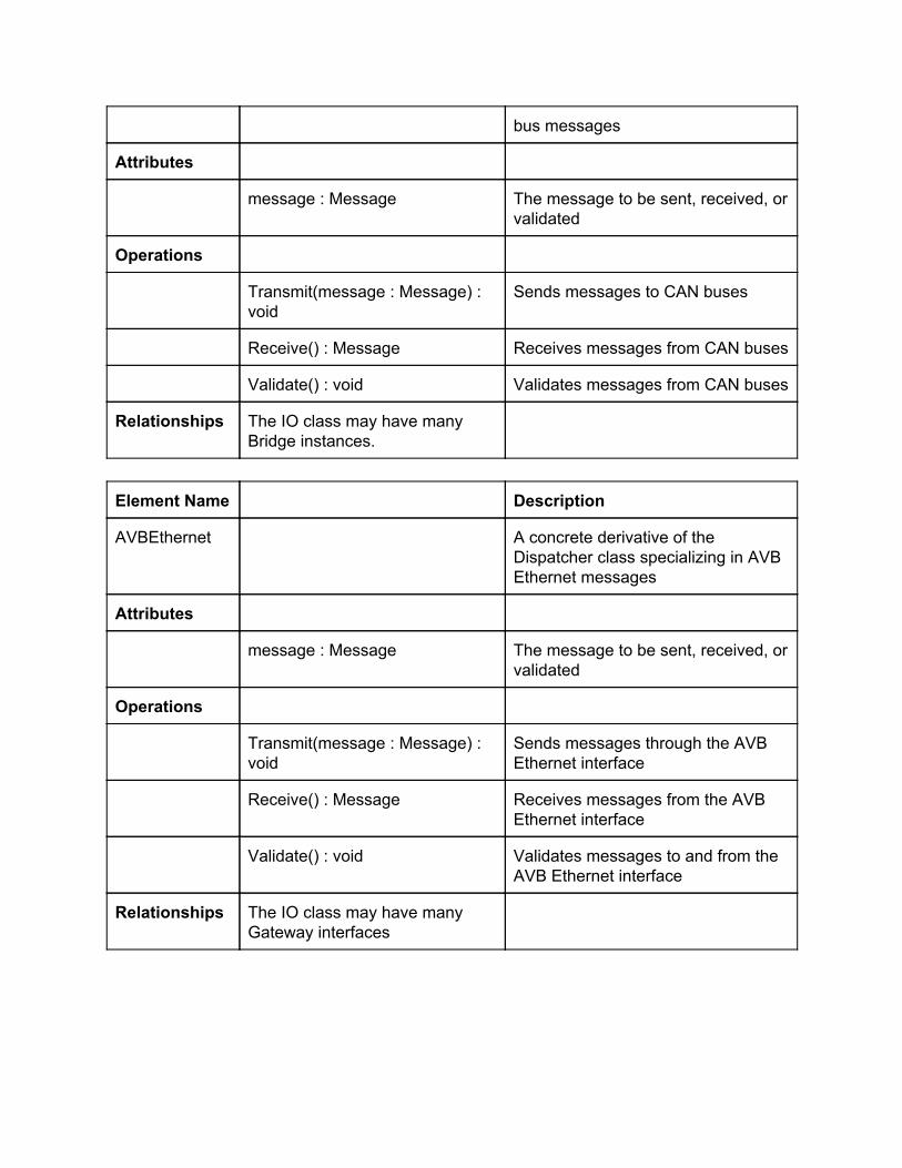
Data DictionaryThe data dictionary provides additional detail for every element in the domain model.
Element Name Description
System Contains core functionality of thegateway, such as programming,power modes, and port control
Attributes
currentState : enum Current state of the system:reprogramming, normal, rebooting
io : IO A pointer to an instance of the IOclass to facilitate sending andreceiving messages
Operations
Program() : void Initiates reprogramming of thegateway
Diag() : void Initiates diagnostic mode of thegateway
Sleep() : void Puts the gateway in sleep mode
Wake() : void Puts the gateway in normal/on mode
Restart() : void Reboots/resets the gateway
Transmit() : void Sends a message from the gatewayto either a CAN bus or the AVBEthernet port
Receive() : void Receives messages from CAN bus ofAVB Ethernet port
MessageTimer() : void Handles timing interval for sendingmessages from the gateway
EnableCANPort(portnumber : int) :void
Enables the specified CAN port
DisableCANPort(portnumber : int): void
Disables the specified CAN port

OnPowerManagement(voltage: int): void
Responds to change notificationsfrom the PowerManagement class.
Relationships The System class keeps a pointerto an instance of the IO class andalso subscribes to thePowerManagement class.
Element Name Description
IO Controls input/output operations forthe system
Attributes
db : DB A pointer to an instance of the DBclass
system : System A pointer to a System instance forcommunication with the core gatewayfunctions
messageRate : float Rate at which messages are passingthrough the system
Operations
DBRead(statement : string) :Message
Prepares a SQL statement to readdata, interacts with the DB class, andreceives response.
DBWrite(statement : string) : void Prepares a SQL statement to writedata to the DB, interacts with the DBclass to insert the data
MessageRead() : Message Reads a message from thedispatcher, and interacts with the restof the IO class to handle as needed
MessageWrite(message :Message)
Prepares a message to send out ofthe gateway and interacts with thecommunications class to send it.
EncryptMessage(messageMessage) : Message
Encrypts messages before they leavethe gateway
DecryptMessage(message :Message) : Message
Decrypts messages after they arereceived by the gateway

DBCacheFlush() : <vector>Message
Interacts with the DB class to retrieveand send all messages that fit specificcriteria for shipment to interfaces
ProgramCANNode() : void Handles communication from AVBethernet connections whenreprogramming CAN nodes
GetFaultCodes() : void Retrieves fault codes from thedatabase when in diagnostic mode
Relationships The IO class interacts withmultiple instances of both thecommunication and Messageclasses, as well and keeping apointer to an instance of the DBclass
Element Name Description
PowerManagement
Monitors the system voltage andnotifies subscribers of changes
Attributes
subscribers : <vector> A list of subscribers to be notified ofpower events
voltage : int Current system voltage
Operations
AddSubscriber() : void Adds a subscriber to be notified
NotifySubscribers() : int Sends a notification to subscribersthat the voltage has changed
ReadVoltage() : int Reads the voltage from the system
Relationships Maintains a onetoone relationshipwith the system class
Element Name Description
DB Handles interaction with the systemdatabase

Attributes
dataFile : string Path to the database file
io : IO A pointer to the IO class, such thatdatabase triggers can initiate IOactions
Operations
Insert(record : string) : void Inserts a record into the database
Select(parameters : string) : void Selects records from the databasebased on given parameters
Delete(parameters : string) : void Deletes records from the databasebased on provided parameters
Update(parameters : string) : void Updates records in the databasebased on provided parameters
Relationships Maintains a onetoone relationshipwith the IO class
Element Name Description
Message Represents an individual message inthe gateway, can be either a CAN orAVB Ethernet message
Attributes
data : string Data of the message
source : string Source address where the messagecame from
destination: string Destination address where themessage will be sent to
Operations
getData() : string Returns the data of the message
setData(_data : string) : void Sets the message data
getSource() : string Gets the source address of themessage

setSource(_source : string) : void Sets the source address of themessage
getDestination() : string Gets the destination address of themessage
setDestination(_destination :string) : void
Sets the destination address of themessage
Relationships Each message has a relationshipwith one IO instance, and each IOinstance may have manymessages
Element Name Description
Communications
An abstract class for sending,receiving, and validating messages
Attributes
message : Message The message to be sent, received, orvalidated
Operations
Transmit(message : Message) :void
Pure virtual function for sendingmessages across the child classinterface
Receive() : Message Pure virtual function that returns amessage to the IO class
Validate() : void Pure virtual function that validatesmessages as they pass through theinterface
Relationships Dispatcher is an abstract class forthe Bridge and Gateway classes,and the IO class may have manydispatchers.
Element Name Description
CAN A concrete derivative of theDispatcher class specialized for CAN
bus messages
Attributes
message : Message The message to be sent, received, orvalidated
Operations
Transmit(message : Message) :void
Sends messages to CAN buses
Receive() : Message Receives messages from CAN buses
Validate() : void Validates messages from CAN buses
Relationships The IO class may have manyBridge instances.
Element Name Description
AVBEthernet A concrete derivative of theDispatcher class specializing in AVBEthernet messages
Attributes
message : Message The message to be sent, received, orvalidated
Operations
Transmit(message : Message) :void
Sends messages through the AVBEthernet interface
Receive() : Message Receives messages from the AVBEthernet interface
Validate() : void Validates messages to and from theAVB Ethernet interface
Relationships The IO class may have manyGateway interfaces

4.3 Sequence DiagramsThe following sequence diagrams show a layout of how the system handles the different usecase scenarios previously detailed. Time flows downward vertically, with the objects representedalong the top.
4.3.1 CAN to CAN CommunicationsWhen a CAN port relays information to the system, the Bridge object will receive the message. Itwill then check if it is a valid message to be forwarded to another location on the system. TheBridge will then send the message to the IO object, where it will be read and decrypted, parsing itinto data, source, and destination. The IO object will then write the message to the database,calling functions from the Database object to store it. Once stored, the IO object reads from thedatabase, reencrypts it, and converts it back into proper message format. Lastly, the messageis transmitted back to the Bridge object to be sent to the proper CAN destination port.
Figure 4.3.1: Sequence diagram for CAN to CAN communications.

4.3.2 CAN to Ethernet CommunicationsCAN to Ethernet communications behave the same as CAN to CAN communications, however,the destination will be specified as the Ethernet port instead of a CAN port. So instead oftransmitting the message back to the Bridge at the end, the message will be sent to the Gatewayobject.
Figure 4.3.2: Sequence diagram for CAN to Ethernet communications.
4.3.3 Ethernet to CAN CommunicationsEthernet to CAN communications behave the same as CAN to Ethernet communications,however, the message originates from the Ethernet port, so the starting object is the Gateway

instead of the Bridge and the destination is the Bridge instead of the Gateway.
Figure 4.3.3: Sequence diagram for Ethernet to CAN communications.
4.3.4 Reprogramming the GatewayInformation from the Ethernet port will be received on the Gateway object, and the message willbe sent to the I/O object and read, then decrypted. The System object then programs the systemand disables all CAN ports. The System then restarts.

Figure 4.3.4: Sequence diagram for reprogramming the Gateway.
4.3.5 Reprogramming CAN portsInformation from the Ethernet port will be received on the Gateway object, and the message willbe sent to the I/O object and read, then decrypted. The System object then programs thespecified CAN nodes with the information from the message.
Figure 4.3.5: Sequence diagram for reprogramming a CAN port.
4.3.6 DiagnosticsInformation from the Ethernet port will be received on the Gateway object, then sent to the I/Oobject, where it will retrieve messages from the database using the Database object. Themessages are read from the database and sent back to the Gateway in the same manner thatmessages are sent in other types of situations.

Figure 4.3.6: Sequence diagram for diagnostics.
4.3.7 Low VoltageOnce the system is on, the System object will initialize an observer pattern to monitor the powerlevel of the system using the Power Management object. The Power Management objectconsistently checks the voltage of the system, and notifies the System object when it dropsbelow 6 volts. In such a case, the system will then enter sleep mode.

Figure 4.3.7: Sequence diagram for low voltage monitoring.
4.4 State DiagramThe figure 4.4 shows all possible states and transitions for the gateway. States are markedusing a roundedged box with a short description of the state. State transitions are signified usingarrows with text descriptions. These descriptions generally consist of a function call and anyconstraints that need to be met before the transition is made. Constraints are indicated usingbrackets. The starting state of a diagram is indicated using a black dot pointing to a state.
Figure 4.4: State diagram for the gateway.

5 PrototypeThe prototype visually simulates what happens on the system in different scenarios. Operationof the gateway can be visualized using seven basic scenarios: data transfer, low voltage,shutdown port, reprogram CAN node, reprogram gateway, IP diagnostics, and denial of service.Each scenario corresponds to each button on the control box.
5.1 Prototype OperationTo run the prototype, a modern web browser with HTML5 and JavaScript support must be used.Supported browser are:
Firefox – 2.0 + Safari – 3.0 + Chrome – 4.0 + IE – 9.0 +
This prototype has not been tested on mobile devices and cannot be guaranteed to run on them.The first version of the prototype can be acessed athttp://www.cse.msu.edu/~cse435/Projects/F2013/Groups/GWAY/Prototype/prototypev1.html.The second version is currently under development and will be available soon.
5.2 Sample ScenariosThe operation for each specific example scenario is detailed below.
5.2.1 Data TransferThe user can specify which ports send and receive the message with the drop downs above thescenario buttons. After the user clicks the “Transfer Data” button, the data packet (yellowsquare) starts from the source node (CAN port 3), goes through the database, and finishes atthe destination (AVB port 1).
The status of the system is also updated as “Selectively read data from the source CAN port,and retransmit the data to the appropriate destination in 8 byte packets with a timestamp, androute it via IP to the specified AVB node”.

Figure 5.2.1: Transferring data from CAN port 3 to AVB port 1.
5.2.2 Remaining supported scenarios:Status of the system will be updated on the Status Console in different scenarios:
Low voltage:"Low voltage threshold detected (>6v), system shutting down.System is off."
Shutdown port:"Can port <number> has been shut down."
Reprogramming CAN node:"Can node reprogrammed.
Reprogramming the Gateway:“Image is being copied to the gateway…Image is being copied to flash…Gateway is rebooting…”
IP Diagnostics:"Fault codes from the database are being forwarded to the IP diagnostics endpoint."
Denial of Service:“Too much traffic is being received from a node on CAN <number>, denial ofservice detected, shutting down CAN port <number>.”

6 References[1] Sys Tec Electronic. “CANEthernet Gateway V2”. [Online]http://www.systecelectronic.com/en/products/industrialcommunication/interfacesandgateways/canethernetgatewayv2 (Accessed: 23 September 2013).
[2] Lucia Bello, “The case for Ethernet in automotive communications”, 2012, University ofCatania, Italy, http://sigbed.seas.upenn.edu/archives/201112/Keynote.pdf
[3] Prototypes V1 GWAY, 26 Oct, 2012,http://www.cse.msu.edu/~cse435/Projects/F2013/Groups/GWAY/Prototype/prototypev1.html
[4] “Controller Area Networks Overview”, November 30, 2011, National Instruments,http://www.ni.com/whitepaper/2732/en/
[5] “AUTOSAR”, Internet: http/www.autosar.org/index.php?p=3&up=1&uup=1&uuup=0[November 4, 2013]
7 Point of ContactFor further information regarding this document and project, please contact Dr. Betty H.C.Cheng at Michigan State University ([email protected]). All materials in this document havebeen sanitized for proprietary data. The students and the instructor gratefully acknowledge theparticipation of our industrial collaborators.