Software Requirements Specification (SRS)cse435/Projects/F2014/Groups/CACC/web/... · The purpose...
27
1 Template based on IEEE Std 830-1998 for SRS. Modifications (content and ordering of information) have been made by Betty H.C. Cheng, Michigan State University (chengb at chengb.cse.msu.edu) Software Requirements Specification (SRS) Cooperative Adaptive Cruise Control System Authors: Andy Lieblich, Elizabeth Florian, Marco Botros, Zachary Ray Customer: William Milam, Ford Motor Company Instructor: Betty H.C. Cheng 1 Introduction This document outlines the requirements of the Cooperative Adaptive Cruise Control system (CACC). Following the introduction, the purpose of this document as well as the scope, definitions, and organization of the project are expanded. After this, the system is described in more detail with respect to product perspective and function as well as user characteristics. This section of the document also describes constraints, assumptions and dependencies, and the appropriation of requirements. To aid in the formalization of the system, a detailed list of requirements is used to capture the overall functionality. Next, models are provided to show visually how the system interacts with users, other vehicles, and the surrounding environment. Finally the prototype is described in detail to give the customer a better idea of how the system functions. The last section of this document gives all references and points of contact for further inquiries about the system. 1.1 Purpose The purpose of the Software Requirements Specification (SRS) is to describe how the CACC system behaves functionally so that the customer understands exactly what is being developed for their desired product. The document also helps to complete the agreement between the developer and customer so that the specified requirements are being implemented to the customer’s satisfaction. The SRS explicitly defines requirements, system behavior through modeling diagrams, and prototypes to aid the customer in their understanding. This document also helps to aid programmers in the solidification of requirements to be implemented and as a general guide to aid future development, improvement, and maintenance.
Transcript of Software Requirements Specification (SRS)cse435/Projects/F2014/Groups/CACC/web/... · The purpose...
1
Template based on IEEE Std 830-1998 for SRS. Modifications (content and ordering of information) have
been made by Betty H.C. Cheng, Michigan State University (chengb at chengb.cse.msu.edu)
Software Requirements Specification (SRS)
Cooperative Adaptive Cruise Control System
Authors: Andy Lieblich, Elizabeth Florian, Marco Botros, Zachary Ray
Customer: William Milam, Ford Motor Company
Instructor: Betty H.C. Cheng
1 Introduction This document outlines the requirements of the Cooperative Adaptive Cruise Control
system (CACC). Following the introduction, the purpose of this document as well as the
scope, definitions, and organization of the project are expanded. After this, the system is
described in more detail with respect to product perspective and function as well as user
characteristics. This section of the document also describes constraints, assumptions and
dependencies, and the appropriation of requirements. To aid in the formalization of the
system, a detailed list of requirements is used to capture the overall functionality. Next,
models are provided to show visually how the system interacts with users, other vehicles,
and the surrounding environment. Finally the prototype is described in detail to give the
customer a better idea of how the system functions. The last section of this document
gives all references and points of contact for further inquiries about the system.
1.1 Purpose
The purpose of the Software Requirements Specification (SRS) is to describe how the
CACC system behaves functionally so that the customer understands exactly what is
being developed for their desired product. The document also helps to complete the
agreement between the developer and customer so that the specified requirements are
being implemented to the customer’s satisfaction.
The SRS explicitly defines requirements, system behavior through modeling diagrams,
and prototypes to aid the customer in their understanding. This document also helps to
aid programmers in the solidification of requirements to be implemented and as a general
guide to aid future development, improvement, and maintenance.
2
Template based on IEEE Std 830-1998 for SRS. Modifications (content and ordering of information) have
been made by Betty H.C. Cheng, Michigan State University (chengb at chengb.cse.msu.edu)
1.2 Scope
The software system being developed is the CACC system. This system is being
implemented as an embedded system for automobiles. The goal of this system is to make
highway travel safer by automating tasks typically handled by a human driver.
The CACC system functions much like the standard cruise control system that most users
are familiar with. The CACC system also utilizes forward facing radar and camera
systems. Both the camera and radar systems work to track vehicles in front of the user’s
vehicle. Once a vehicle has been detected, the CACC system automatically decreases the
user’s vehicle to the following distance specified by the user. After a vehicle is detected
the user has the option to start or join a platoon. Once the user is part of a platoon, the
vehicle communicates via radio to other vehicles in the platoon to get their GPS
information including speed, position, and direction of travel. Once the system is
engaged, the user has the option to increase or decrease the speed by increments of one
mile per hour. The user is still responsible for keeping their vehicle in its lane as the
system only affects the vehicle’s forward motion. The GPS system then works to help
detect possible collisions. Since all of the vehicles in the platoon are sharing information,
if one vehicle has to stop suddenly, then there is a significantly reduced chance of getting
into an accident because all of the vehicles are connected and can share data almost
instantly effectively making highway cruise control safer.
1.3 Definitions, acronyms, and abbreviations
Table 1.1 contains the definitions of all terms, acronyms, and abbreviations used in this
document.
Term Description
CACC The Cooperative Adaptive Cruise Control software system is responsible for tracking
other vehicles through GPS, radar, and camera systems and adjusting the braking and
acceleration of a user's vehicle accordingly
GPS The Global Positioning System is used to determine where a vehicle is, what speed
the vehicle is traveling at, and what direction the vehicle is headed. This system is
also used to help track and detect possible collisions between vehicles in the platoon
Lead Vehicle The vehicle at the front most position in the platoon that sets the speed of the platoon
Platoon A group of vehicles all engaged in the Cooperative Adaptive Cruise Control system.
The group may only travel in a single lane. A vehicle leaving the lane results in the
vehicle leaving the platoon
Target Vehicle The vehicle directly in front of the user’s vehicle. This is the vehicle that will be
tracked by the camera and radar systems
Trailing Vehicle The vehicle directly behind the user’s vehicle
CAN BUS The Controller Area Network Bus is the primary way that subsystems in the vehicle
will communicate with each other
VC The Vehicle Controller is responsible for coordinating all CACC subsystems and
3
Template based on IEEE Std 830-1998 for SRS. Modifications (content and ordering of information) have
been made by Betty H.C. Cheng, Michigan State University (chengb at chengb.cse.msu.edu)
ultimately the main controller of the vehicle’s throttle and braking systems
ETC The Electronic Throttle Control is responsible for managing the power of the engine
CC The Cruise Control system ensures speed of the vehicle is constant and equal to the
speed set by the user
ACC The Adaptive Cruise Control system controls a vehicle’s acceleration and braking
depending on the location of the vehicle in front of it
Performance
Envelope A data set shared between vehicles in a platoon that describe a vehicle’s acceleration
and braking capabilities
Table 1.1: Definitions, acronyms, and abbreviations
1.4 Organization
Following the introduction of the CACC system the SRS describes the system in further
detail. The SRS does this by defining system design and layout through product
perspective and function as well as user characteristics and constraints. The CACC
system is then described in terms of requirements and accompanying models. Finally the
system prototype is explained as a practical implementation of the listed models. Lastly
references and points of contact are listed.
2 Overall Description This section provides a detailed description of the system. First the system’s functionality,
constraints, use prerequisites, and dependencies are discussed. This section also discusses the
context in which the system is used and what other subsystems it makes use of.
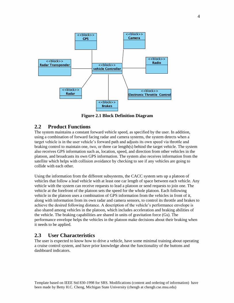
2.1 Product Perspective The CACC system will work closely with different subsystems in the vehicle. As shown in
Figure 2.1 below, the system receives information from the radar, GPS, and camera systems. The
system then sends this information to the radio where it is broadcast to other vehicles in the
platoon. The system also controls the Electronic Throttle Control system (ETC) and the Braking
system. Both of these subsystems work to control the speed of the vehicle. The system works with the limited resources of processing and memory in the vehicle while still
being very reliable. The system works in the current context of the vehicle using the Controller
Area Network (CAN) bus. The system also uses different peripherals that are shared between
systems. For instance, the camera is also used by the lane keeping system which is separate from
CACC. The user is also able to interact with the system easily. In the event of software failure,
the system informs the user that they are resuming control of the vehicle.
4
Template based on IEEE Std 830-1998 for SRS. Modifications (content and ordering of information) have
been made by Betty H.C. Cheng, Michigan State University (chengb at chengb.cse.msu.edu)
Figure 2.1 Block Definition Diagram
2.2 Product Functions The system maintains a constant forward vehicle speed, as specified by the user. In addition,
using a combination of forward facing radar and camera systems, the system detects when a
target vehicle is in the user vehicle’s forward path and adjusts its own speed via throttle and
braking control to maintain one, two, or three car length(s) behind the target vehicle. The system
also receives GPS information such as, location, speed, and direction from other vehicles in the
platoon, and broadcasts its own GPS information. The system also receives information from the
satellite which helps with collision avoidance by checking to see if any vehicles are going to
collide with each other. Using the information from the different subsystems, the CACC system sets up a platoon of
vehicles that follow a lead vehicle with at least one car length of space between each vehicle. Any
vehicle with the system can receive requests to lead a platoon or send requests to join one. The
vehicle at the forefront of the platoon sets the speed for the whole platoon. Each following
vehicle in the platoon uses a combination of GPS information from the vehicles in front of it,
along with information from its own radar and camera sensors, to control its throttle and brakes to
achieve the desired following distance. A description of the vehicle’s performance envelope is
also shared among vehicles in the platoon, which includes acceleration and braking abilities of
the vehicle. The braking capabilities are shared in units of gravitation force (Gs). The
performance envelope helps the vehicles in the platoon make decisions about their braking when
it needs to be applied.
2.3 User Characteristics The user is expected to know how to drive a vehicle, have some minimal training about operating
a cruise control system, and have prior knowledge about the functionality of the buttons and
dashboard indicators.
5
Template based on IEEE Std 830-1998 for SRS. Modifications (content and ordering of information) have
been made by Betty H.C. Cheng, Michigan State University (chengb at chengb.cse.msu.edu)
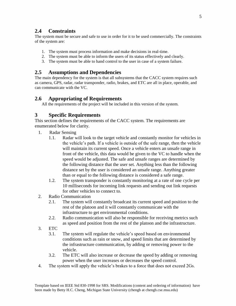
2.4 Constraints The system must be secure and safe to use in order for it to be used commercially. The constraints
of the system are:
1. The system must process information and make decisions in real-time.
2. The system must be able to inform the users of its status effectively and clearly.
3. The system must be able to hand control to the user in case of a system failure.
2.5 Assumptions and Dependencies The main dependency for the system is that all subsystems that the CACC system requires such
as camera, GPS, radar, radar transponder, radio, brakes, and ETC are all in place, operable, and
can communicate with the VC.
2.6 Appropriating of Requirements All the requirements of the project will be included in this version of the system.
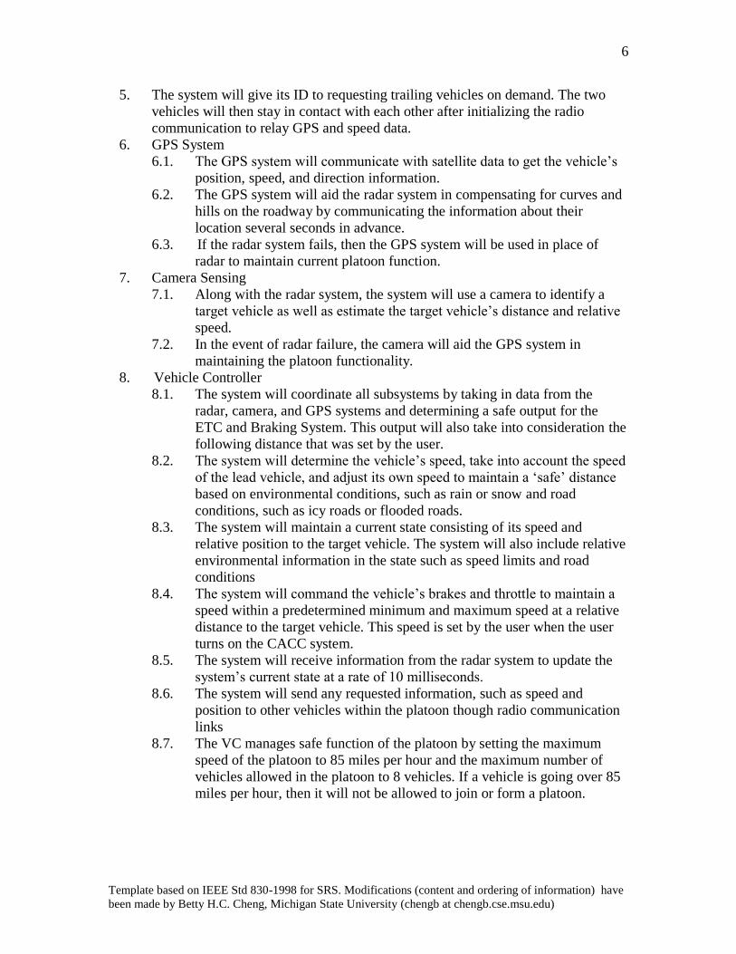
3 Specific Requirements This section defines the requirements of the CACC system. The requirements are
enumerated below for clarity.
1. Radar Sensing
1.1. Radar will look to the target vehicle and constantly monitor for vehicles in
the vehicle’s path. If a vehicle is outside of the safe range, then the vehicle
will maintain its current speed. Once a vehicle enters an unsafe range in
front of the vehicle, this data would be given to the VC to handle when the
speed would be adjusted. The safe and unsafe ranges are determined by
the following distance that the user set. Anything less than the following
distance set by the user is considered an unsafe range. Anything greater
than or equal to the following distance is considered a safe range.
1.2. The system transponder is constantly monitoring at a rate of one cycle per
10 milliseconds for incoming link requests and sending out link requests
for other vehicles to connect to.
2. Radio Communication
2.1. The system will constantly broadcast its current speed and position to the
rest of the platoon and it will constantly communicate with the
infrastructure to get environmental conditions.
2.2. Radio communication will also be responsible for receiving metrics such
as speed and position from the rest of the platoon and the infrastructure.
3. ETC
3.1. The system will regulate the vehicle’s speed based on environmental
conditions such as rain or snow, and speed limits that are determined by
the infrastructure communication, by adding or removing power to the
vehicle.
3.2. The ETC will also increase or decrease the speed by adding or removing
power when the user increases or decreases the speed control.
4. The system will apply the vehicle’s brakes to a force that does not exceed 2Gs.
6
Template based on IEEE Std 830-1998 for SRS. Modifications (content and ordering of information) have
been made by Betty H.C. Cheng, Michigan State University (chengb at chengb.cse.msu.edu)
5. The system will give its ID to requesting trailing vehicles on demand. The two
vehicles will then stay in contact with each other after initializing the radio
communication to relay GPS and speed data.
6. GPS System
6.1. The GPS system will communicate with satellite data to get the vehicle’s
position, speed, and direction information.
6.2. The GPS system will aid the radar system in compensating for curves and
hills on the roadway by communicating the information about their
location several seconds in advance.
6.3. If the radar system fails, then the GPS system will be used in place of
radar to maintain current platoon function.
7. Camera Sensing
7.1. Along with the radar system, the system will use a camera to identify a
target vehicle as well as estimate the target vehicle’s distance and relative
speed.
7.2. In the event of radar failure, the camera will aid the GPS system in
maintaining the platoon functionality.
8. Vehicle Controller
8.1. The system will coordinate all subsystems by taking in data from the
radar, camera, and GPS systems and determining a safe output for the
ETC and Braking System. This output will also take into consideration the
following distance that was set by the user.
8.2. The system will determine the vehicle’s speed, take into account the speed
of the lead vehicle, and adjust its own speed to maintain a ‘safe’ distance
based on environmental conditions, such as rain or snow and road
conditions, such as icy roads or flooded roads.
8.3. The system will maintain a current state consisting of its speed and
relative position to the target vehicle. The system will also include relative
environmental information in the state such as speed limits and road
conditions
8.4. The system will command the vehicle’s brakes and throttle to maintain a
speed within a predetermined minimum and maximum speed at a relative
distance to the target vehicle. This speed is set by the user when the user
turns on the CACC system.
8.5. The system will receive information from the radar system to update the
system’s current state at a rate of 10 milliseconds.
8.6. The system will send any requested information, such as speed and
position to other vehicles within the platoon though radio communication
links
8.7. The VC manages safe function of the platoon by setting the maximum
speed of the platoon to 85 miles per hour and the maximum number of
vehicles allowed in the platoon to 8 vehicles. If a vehicle is going over 85
miles per hour, then it will not be allowed to join or form a platoon.
7
Template based on IEEE Std 830-1998 for SRS. Modifications (content and ordering of information) have
been made by Betty H.C. Cheng, Michigan State University (chengb at chengb.cse.msu.edu)
4 Modeling Requirements In order to give both the customer and developers a better understanding of the how the
CACC system functions, the following sections give examples of models of the system.
Use cases are first expanded followed by the domain model and data dictionary. Finally
sequence diagrams are showcased and the section is closed with system state diagrams.
4.1 Use Cases
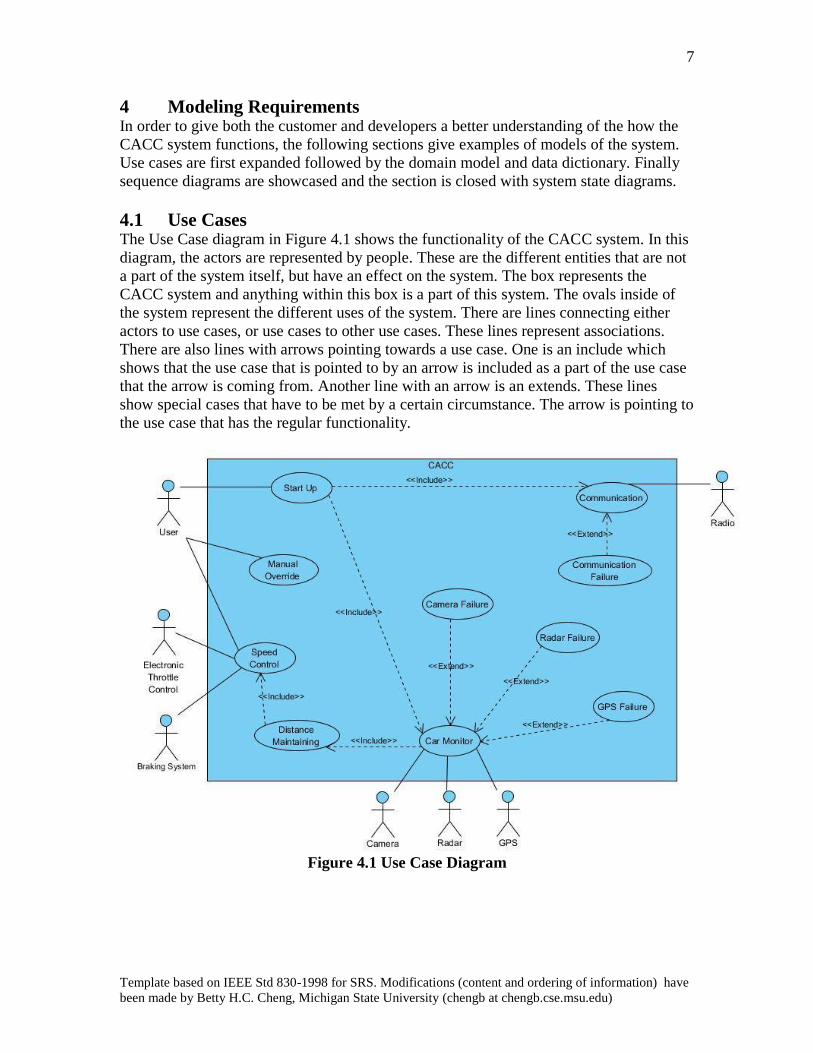
The Use Case diagram in Figure 4.1 shows the functionality of the CACC system. In this
diagram, the actors are represented by people. These are the different entities that are not
a part of the system itself, but have an effect on the system. The box represents the
CACC system and anything within this box is a part of this system. The ovals inside of
the system represent the different uses of the system. There are lines connecting either
actors to use cases, or use cases to other use cases. These lines represent associations.
There are also lines with arrows pointing towards a use case. One is an include which
shows that the use case that is pointed to by an arrow is included as a part of the use case
that the arrow is coming from. Another line with an arrow is an extends. These lines
show special cases that have to be met by a certain circumstance. The arrow is pointing to
the use case that has the regular functionality.
Figure 4.1 Use Case Diagram
8
Template based on IEEE Std 830-1998 for SRS. Modifications (content and ordering of information) have
been made by Betty H.C. Cheng, Michigan State University (chengb at chengb.cse.msu.edu)
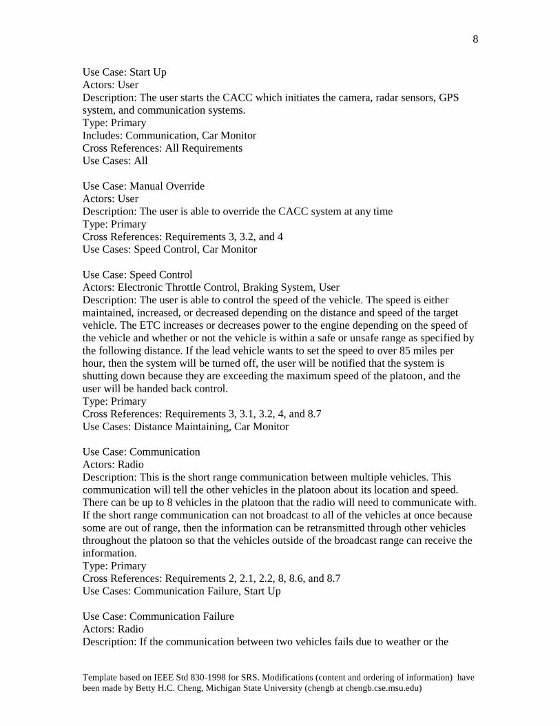
Use Case: Start Up
Actors: User
Description: The user starts the CACC which initiates the camera, radar sensors, GPS
system, and communication systems.
Type: Primary
Includes: Communication, Car Monitor
Cross References: All Requirements
Use Cases: All
Use Case: Manual Override
Actors: User
Description: The user is able to override the CACC system at any time
Type: Primary
Cross References: Requirements 3, 3.2, and 4
Use Cases: Speed Control, Car Monitor
Use Case: Speed Control
Actors: Electronic Throttle Control, Braking System, User
Description: The user is able to control the speed of the vehicle. The speed is either
maintained, increased, or decreased depending on the distance and speed of the target
vehicle. The ETC increases or decreases power to the engine depending on the speed of
the vehicle and whether or not the vehicle is within a safe or unsafe range as specified by
the following distance. If the lead vehicle wants to set the speed to over 85 miles per
hour, then the system will be turned off, the user will be notified that the system is
shutting down because they are exceeding the maximum speed of the platoon, and the
user will be handed back control.
Type: Primary
Cross References: Requirements 3, 3.1, 3.2, 4, and 8.7
Use Cases: Distance Maintaining, Car Monitor
Use Case: Communication
Actors: Radio
Description: This is the short range communication between multiple vehicles. This
communication will tell the other vehicles in the platoon about its location and speed.
There can be up to 8 vehicles in the platoon that the radio will need to communicate with.
If the short range communication can not broadcast to all of the vehicles at once because
some are out of range, then the information can be retransmitted through other vehicles
throughout the platoon so that the vehicles outside of the broadcast range can receive the
information.
Type: Primary
Cross References: Requirements 2, 2.1, 2.2, 8, 8.6, and 8.7
Use Cases: Communication Failure, Start Up
Use Case: Communication Failure
Actors: Radio
Description: If the communication between two vehicles fails due to weather or the
9
Template based on IEEE Std 830-1998 for SRS. Modifications (content and ordering of information) have
been made by Betty H.C. Cheng, Michigan State University (chengb at chengb.cse.msu.edu)
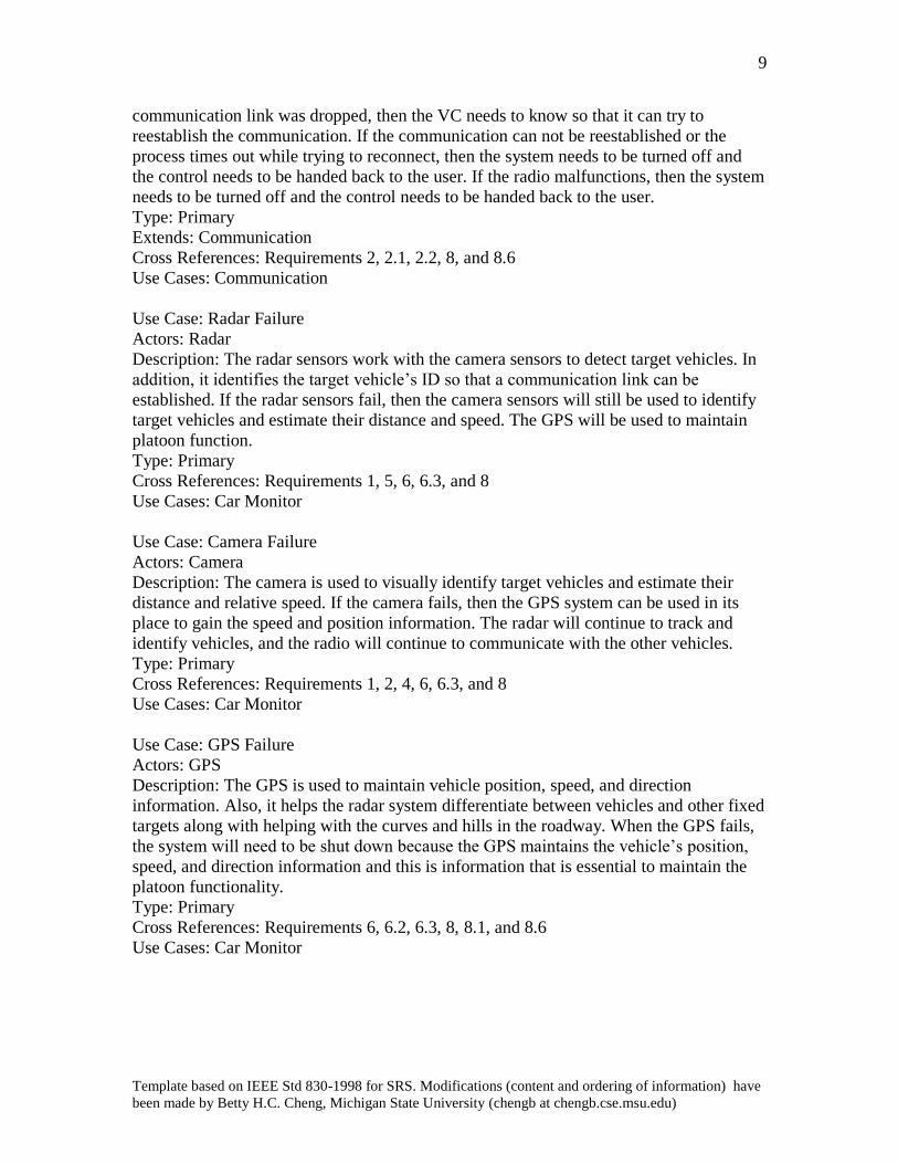
communication link was dropped, then the VC needs to know so that it can try to
reestablish the communication. If the communication can not be reestablished or the
process times out while trying to reconnect, then the system needs to be turned off and
the control needs to be handed back to the user. If the radio malfunctions, then the system
needs to be turned off and the control needs to be handed back to the user.
Type: Primary
Extends: Communication
Cross References: Requirements 2, 2.1, 2.2, 8, and 8.6
Use Cases: Communication
Use Case: Radar Failure
Actors: Radar
Description: The radar sensors work with the camera sensors to detect target vehicles. In
addition, it identifies the target vehicle’s ID so that a communication link can be
established. If the radar sensors fail, then the camera sensors will still be used to identify
target vehicles and estimate their distance and speed. The GPS will be used to maintain
platoon function.
Type: Primary
Cross References: Requirements 1, 5, 6, 6.3, and 8
Use Cases: Car Monitor
Use Case: Camera Failure
Actors: Camera
Description: The camera is used to visually identify target vehicles and estimate their
distance and relative speed. If the camera fails, then the GPS system can be used in its
place to gain the speed and position information. The radar will continue to track and
identify vehicles, and the radio will continue to communicate with the other vehicles.
Type: Primary
Cross References: Requirements 1, 2, 4, 6, 6.3, and 8
Use Cases: Car Monitor
Use Case: GPS Failure
Actors: GPS
Description: The GPS is used to maintain vehicle position, speed, and direction
information. Also, it helps the radar system differentiate between vehicles and other fixed
targets along with helping with the curves and hills in the roadway. When the GPS fails,
the system will need to be shut down because the GPS maintains the vehicle’s position,
speed, and direction information and this is information that is essential to maintain the
platoon functionality.
Type: Primary
Cross References: Requirements 6, 6.2, 6.3, 8, 8.1, and 8.6
Use Cases: Car Monitor
10
Template based on IEEE Std 830-1998 for SRS. Modifications (content and ordering of information) have
been made by Betty H.C. Cheng, Michigan State University (chengb at chengb.cse.msu.edu)
Use Case: Car Monitor
Actors: Radar, Camera, GPS
Description: This use case contains the radar, camera, and GPS systems that work
together to carry out the following functions: detect other vehicles, maintain position,
maintain speed, and collect the directional information on other vehicles. This will also
be used to differentiate between vehicles and fixed objects as well as compensate for hills
and curves in the roadway.
Type: Primary
Includes: Distance Maintaining
Cross References: Requirements 1, 1.1, 1.2, 3, 3.1, 3.2, 4, 5, 6, 6.1, 6.2, 6.3, 7, 7.1, 7.2, 8,
8.1, 8.2, 8.3, 8.4, and 8.5
Use Cases: All
Use Case: Distance Maintaining
Actors: Radar, Camera, GPS, Electronic Throttle Control, Braking System
Description: The GPS, camera, radar, and radio systems work together to detect other
vehicles and gain information about their speed, direction, and position. It uses this
information to maintain a safe distance from the target vehicle.
Type: Primary
Includes: Speed Control
Cross References: All Requirements
Use Cases: Speed Control, Car Monitor, Communication
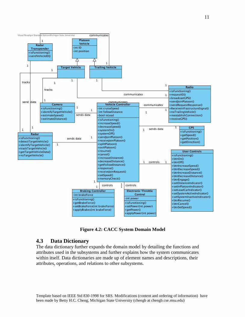
4.2 Domain Model The domain model gives a visualization of how the major system components
communicate with each other. Each box represents a subsystem of the CACC system.
Each line represents a communication link between the subsystems. This means that the
subsystems can directly talk to each other through the given operations of each
subsystem. Figure 4.2 below gives a representation of the CACC domain model.
11
Template based on IEEE Std 830-1998 for SRS. Modifications (content and ordering of information) have
been made by Betty H.C. Cheng, Michigan State University (chengb at chengb.cse.msu.edu)
Figure 4.2: CACC System Domain Model
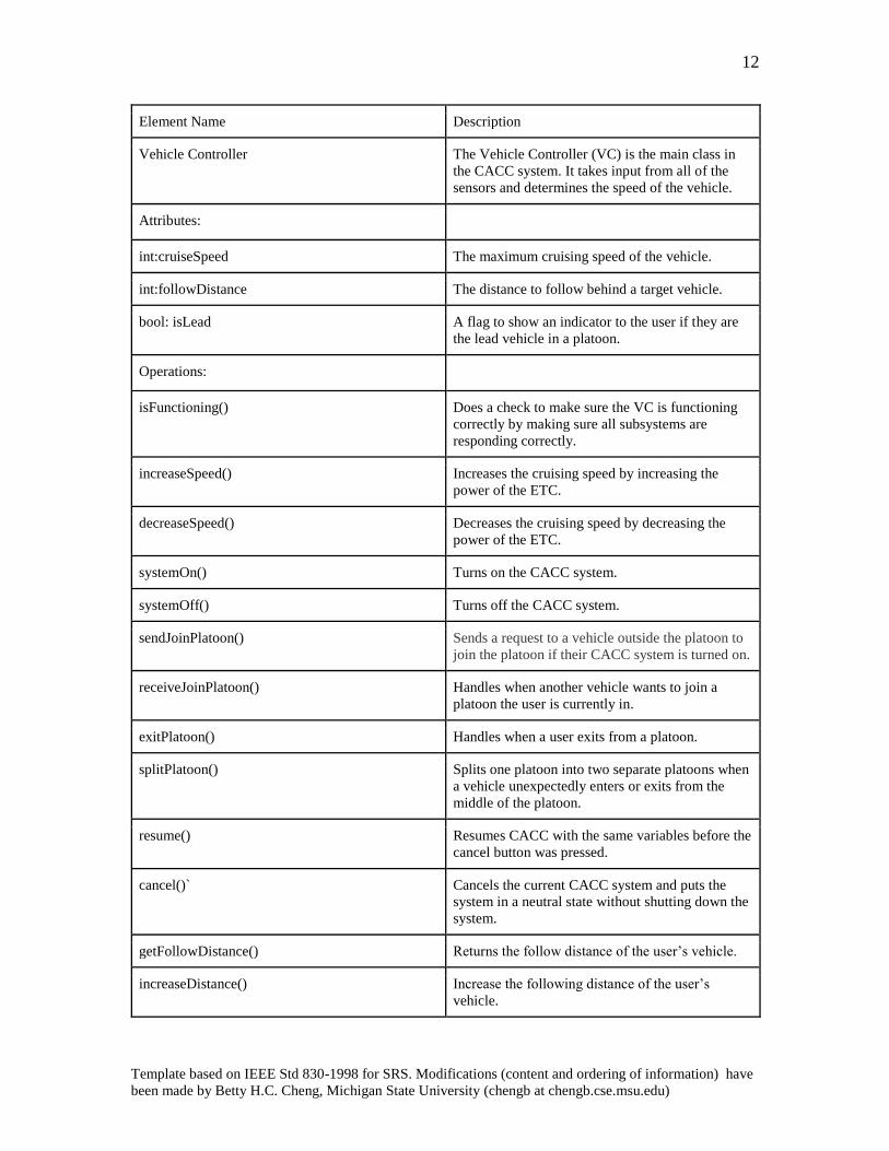
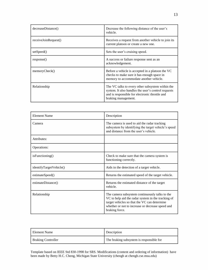
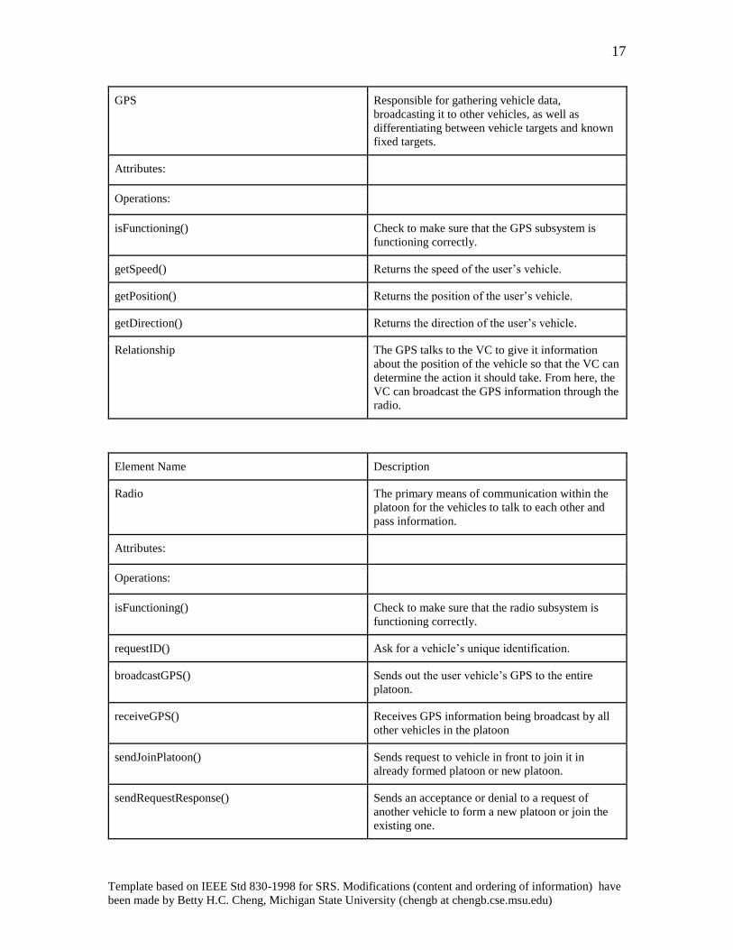
4.3 Data Dictionary
The data dictionary further expands the domain model by detailing the functions and
attributes used in the subsystems and further explains how the system communicates
within itself. Data dictionaries are made up of element names and descriptions, their
attributes, operations, and relations to other subsystems.
12
Template based on IEEE Std 830-1998 for SRS. Modifications (content and ordering of information) have
been made by Betty H.C. Cheng, Michigan State University (chengb at chengb.cse.msu.edu)
Element Name Description
Vehicle Controller The Vehicle Controller (VC) is the main class in
the CACC system. It takes input from all of the
sensors and determines the speed of the vehicle.
Attributes:
int:cruiseSpeed The maximum cruising speed of the vehicle.
int:followDistance The distance to follow behind a target vehicle.
bool: isLead A flag to show an indicator to the user if they are
the lead vehicle in a platoon.
Operations:
isFunctioning() Does a check to make sure the VC is functioning
correctly by making sure all subsystems are
responding correctly.
increaseSpeed() Increases the cruising speed by increasing the
power of the ETC.
decreaseSpeed() Decreases the cruising speed by decreasing the
power of the ETC.
systemOn() Turns on the CACC system.
systemOff() Turns off the CACC system.
sendJoinPlatoon() Sends a request to a vehicle outside the platoon to
join the platoon if their CACC system is turned on.
receiveJoinPlatoon() Handles when another vehicle wants to join a
platoon the user is currently in.
exitPlatoon() Handles when a user exits from a platoon.
splitPlatoon() Splits one platoon into two separate platoons when
a vehicle unexpectedly enters or exits from the
middle of the platoon.
resume() Resumes CACC with the same variables before the
cancel button was pressed.
cancel()` Cancels the current CACC system and puts the
system in a neutral state without shutting down the
system.
getFollowDistance() Returns the follow distance of the user’s vehicle.
increaseDistance() Increase the following distance of the user’s
vehicle.
13
Template based on IEEE Std 830-1998 for SRS. Modifications (content and ordering of information) have
been made by Betty H.C. Cheng, Michigan State University (chengb at chengb.cse.msu.edu)
decreaseDistance() Decrease the following distance of the user’s
vehicle.
receiveJoinRequest() Receives a request from another vehicle to join its
current platoon or create a new one.
setSpeed() Sets the user’s cruising speed.
response() A success or failure response sent as an
acknowledgement.
memoryCheck() Before a vehicle is accepted in a platoon the VC
checks to make sure it has enough space in
memory to accommodate another vehicle.
Relationship The VC talks to every other subsystem within the
system. It also handles the user’s control requests
and is responsible for electronic throttle and
braking management.
Element Name Description
Camera The camera is used to aid the radar tracking
subsystem by identifying the target vehicle’s speed
and distance from the user’s vehicle.
Attributes:
Operations:
isFunctioning() Check to make sure that the camera system is
functioning correctly.
identifyTargetVehicle() Aids in the detection of a target vehicle.
estimateSpeed() Returns the estimated speed of the target vehicle.
estimateDistance() Returns the estimated distance of the target
vehicle.
Relationship The camera subsystem continuously talks to the
VC to help aid the radar system in the tracking of
target vehicles so that the VC can determine
whether or not to increase or decrease speed and
braking force.
Element Name Description
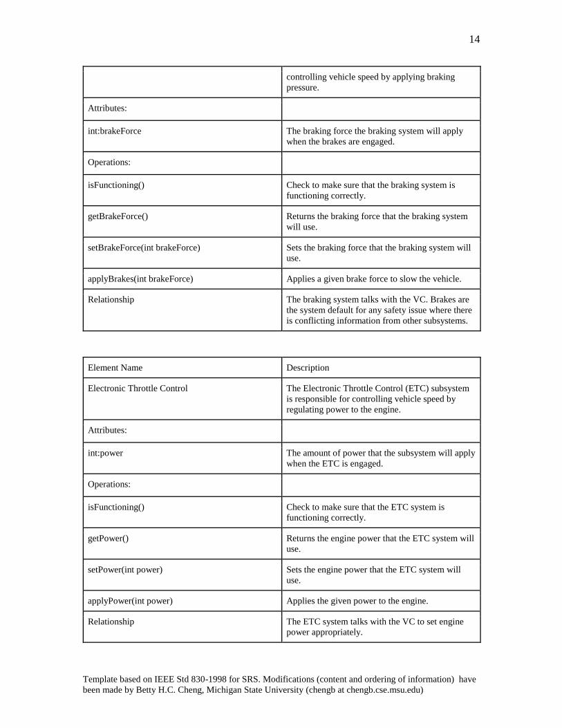
Braking Controller The braking subsystem is responsible for
14
Template based on IEEE Std 830-1998 for SRS. Modifications (content and ordering of information) have
been made by Betty H.C. Cheng, Michigan State University (chengb at chengb.cse.msu.edu)
controlling vehicle speed by applying braking
pressure.
Attributes:
int:brakeForce The braking force the braking system will apply
when the brakes are engaged.
Operations:
isFunctioning() Check to make sure that the braking system is
functioning correctly.
getBrakeForce() Returns the braking force that the braking system
will use.
setBrakeForce(int brakeForce) Sets the braking force that the braking system will
use.
applyBrakes(int brakeForce) Applies a given brake force to slow the vehicle.
Relationship The braking system talks with the VC. Brakes are
the system default for any safety issue where there
is conflicting information from other subsystems.
Element Name Description
Electronic Throttle Control The Electronic Throttle Control (ETC) subsystem
is responsible for controlling vehicle speed by
regulating power to the engine.
Attributes:
int:power The amount of power that the subsystem will apply
when the ETC is engaged.
Operations:
isFunctioning() Check to make sure that the ETC system is
functioning correctly.
getPower() Returns the engine power that the ETC system will
use.
setPower(int power) Sets the engine power that the ETC system will
use.
applyPower(int power) Applies the given power to the engine.
Relationship The ETC system talks with the VC to set engine
power appropriately.
15
Template based on IEEE Std 830-1998 for SRS. Modifications (content and ordering of information) have
been made by Betty H.C. Cheng, Michigan State University (chengb at chengb.cse.msu.edu)
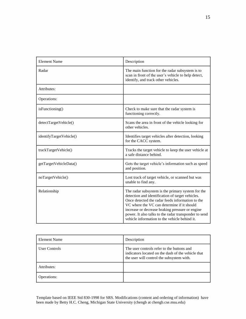
Element Name Description
Radar The main function for the radar subsystem is to
scan in front of the user’s vehicle to help detect,
identify, and track other vehicles.
Attributes:
Operations:
isFunctioning() Check to make sure that the radar system is
functioning correctly.
detectTargetVehicle() Scans the area in front of the vehicle looking for
other vehicles.
identifyTargetVehicle() Identifies target vehicles after detection, looking
for the CACC system.
trackTargetVehicle() Tracks the target vehicle to keep the user vehicle at
a safe distance behind.
getTargetVehicleData() Gets the target vehicle’s information such as speed
and position.
noTargetVehicle() Lost track of target vehicle, or scanned but was
unable to find any.
Relationship The radar subsystem is the primary system for the
detection and identification of target vehicles.
Once detected the radar feeds information to the
VC where the VC can determine if it should
increase or decrease braking pressure or engine
power. It also talks to the radar transponder to send
vehicle information to the vehicle behind it.
Element Name Description
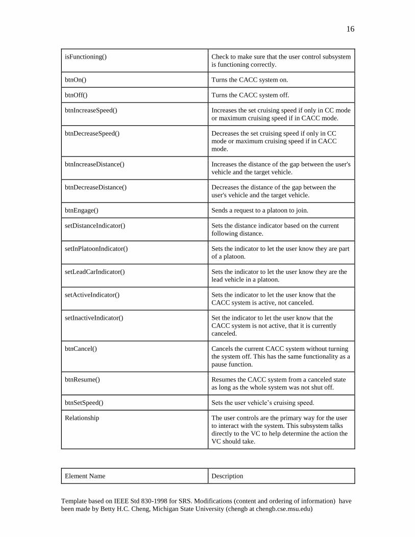
User Controls The user controls refer to the buttons and
indicators located on the dash of the vehicle that
the user will control the subsystem with.
Attributes:
Operations:
16
Template based on IEEE Std 830-1998 for SRS. Modifications (content and ordering of information) have
been made by Betty H.C. Cheng, Michigan State University (chengb at chengb.cse.msu.edu)
isFunctioning() Check to make sure that the user control subsystem
is functioning correctly.
btnOn() Turns the CACC system on.
btnOff() Turns the CACC system off.
btnIncreaseSpeed() Increases the set cruising speed if only in CC mode
or maximum cruising speed if in CACC mode.
btnDecreaseSpeed() Decreases the set cruising speed if only in CC
mode or maximum cruising speed if in CACC
mode.
btnIncreaseDistance() Increases the distance of the gap between the user's
vehicle and the target vehicle.
btnDecreaseDistance() Decreases the distance of the gap between the
user's vehicle and the target vehicle.
btnEngage() Sends a request to a platoon to join.
setDistanceIndicator() Sets the distance indicator based on the current
following distance.
setInPlatoonIndicator() Sets the indicator to let the user know they are part
of a platoon.
setLeadCarIndicator() Sets the indicator to let the user know they are the
lead vehicle in a platoon.
setActiveIndicator() Sets the indicator to let the user know that the
CACC system is active, not canceled.
setInactiveIndicator() Set the indicator to let the user know that the
CACC system is not active, that it is currently
canceled.
btnCancel() Cancels the current CACC system without turning
the system off. This has the same functionality as a
pause function.
btnResume() Resumes the CACC system from a canceled state
as long as the whole system was not shut off.
btnSetSpeed() Sets the user vehicle’s cruising speed.
Relationship The user controls are the primary way for the user
to interact with the system. This subsystem talks
directly to the VC to help determine the action the
VC should take.
Element Name Description
17
Template based on IEEE Std 830-1998 for SRS. Modifications (content and ordering of information) have
been made by Betty H.C. Cheng, Michigan State University (chengb at chengb.cse.msu.edu)
GPS Responsible for gathering vehicle data,
broadcasting it to other vehicles, as well as
differentiating between vehicle targets and known
fixed targets.
Attributes:
Operations:
isFunctioning() Check to make sure that the GPS subsystem is
functioning correctly.
getSpeed() Returns the speed of the user’s vehicle.
getPosition() Returns the position of the user’s vehicle.
getDirection() Returns the direction of the user’s vehicle.
Relationship The GPS talks to the VC to give it information
about the position of the vehicle so that the VC can
determine the action it should take. From here, the
VC can broadcast the GPS information through the
radio.
Element Name Description
Radio The primary means of communication within the
platoon for the vehicles to talk to each other and
pass information.
Attributes:
Operations:
isFunctioning() Check to make sure that the radio subsystem is
functioning correctly.
requestID() Ask for a vehicle’s unique identification.
broadcastGPS() Sends out the user vehicle’s GPS to the entire
platoon.
receiveGPS() Receives GPS information being broadcast by all
other vehicles in the platoon
sendJoinPlatoon() Sends request to vehicle in front to join it in
already formed platoon or new platoon.
sendRequestResponse() Sends an acceptance or denial to a request of
another vehicle to form a new platoon or join the
existing one.
18
Template based on IEEE Std 830-1998 for SRS. Modifications (content and ordering of information) have
been made by Betty H.C. Cheng, Michigan State University (chengb at chengb.cse.msu.edu)
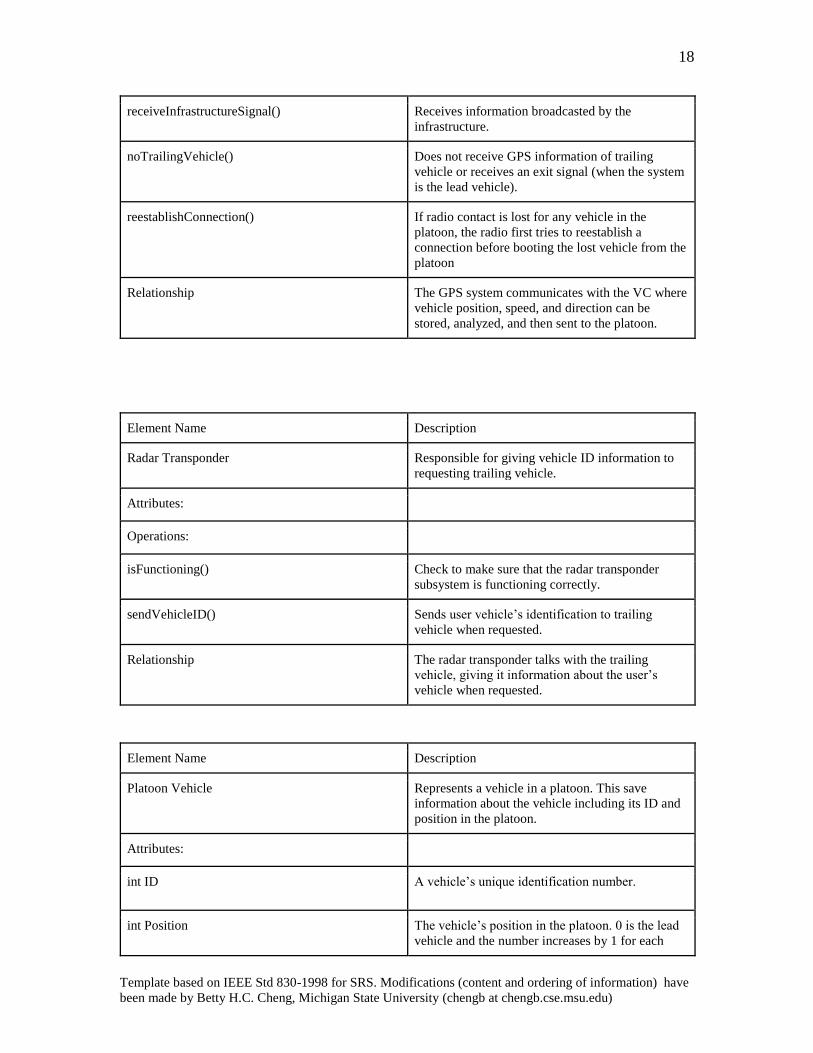
receiveInfrastructureSignal() Receives information broadcasted by the
infrastructure.
noTrailingVehicle() Does not receive GPS information of trailing
vehicle or receives an exit signal (when the system
is the lead vehicle).
reestablishConnection() If radio contact is lost for any vehicle in the
platoon, the radio first tries to reestablish a
connection before booting the lost vehicle from the
platoon
Relationship The GPS system communicates with the VC where
vehicle position, speed, and direction can be
stored, analyzed, and then sent to the platoon.
Element Name Description
Radar Transponder Responsible for giving vehicle ID information to
requesting trailing vehicle.
Attributes:
Operations:
isFunctioning() Check to make sure that the radar transponder
subsystem is functioning correctly.
sendVehicleID() Sends user vehicle’s identification to trailing
vehicle when requested.
Relationship The radar transponder talks with the trailing
vehicle, giving it information about the user’s
vehicle when requested.
Element Name Description
Platoon Vehicle Represents a vehicle in a platoon. This save
information about the vehicle including its ID and
position in the platoon.
Attributes:
int ID A vehicle’s unique identification number.
int Position The vehicle’s position in the platoon. 0 is the lead
vehicle and the number increases by 1 for each
19
Template based on IEEE Std 830-1998 for SRS. Modifications (content and ordering of information) have
been made by Betty H.C. Cheng, Michigan State University (chengb at chengb.cse.msu.edu)
position in the platoon.
Operations:
Relationship Platoon vehicles interact with the camera, radar,
radar transponder, and radio subsystem to
effectively communicate vehicle information to the
other vehicles in a platoon.
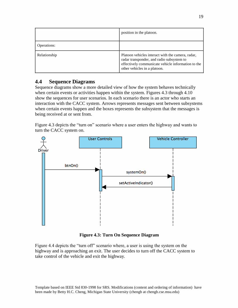
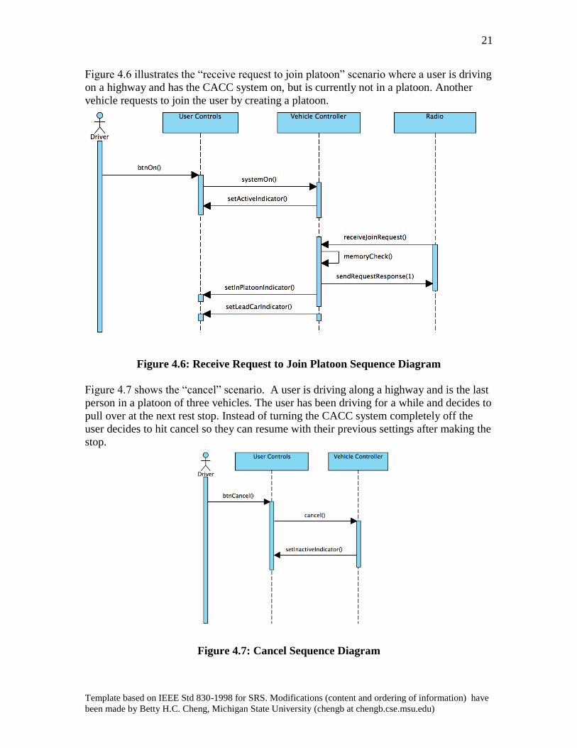
4.4 Sequence Diagrams
Sequence diagrams show a more detailed view of how the system behaves technically
when certain events or activities happen within the system. Figures 4.3 through 4.10
show the sequences for user scenarios. In each scenario there is an actor who starts an
interaction with the CACC system. Arrows represents messages sent between subsystems
when certain events happen and the boxes represents the subsystem that the messages is
being received at or sent from.
Figure 4.3 depicts the “turn on” scenario where a user enters the highway and wants to
turn the CACC system on.
Figure 4.3: Turn On Sequence Diagram
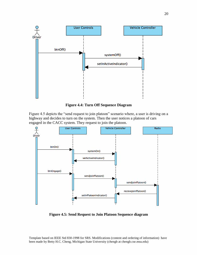
Figure 4.4 depicts the “turn off” scenario where, a user is using the system on the
highway and is approaching an exit. The user decides to turn off the CACC system to
take control of the vehicle and exit the highway.
20
Template based on IEEE Std 830-1998 for SRS. Modifications (content and ordering of information) have
been made by Betty H.C. Cheng, Michigan State University (chengb at chengb.cse.msu.edu)
Figure 4.4: Turn Off Sequence Diagram
Figure 4.5 depicts the “send request to join platoon” scenario where, a user is driving on a
highway and decides to turn on the system. Then the user notices a platoon of cars
engaged in the CACC system. They request to join the platoon.
Figure 4.5: Send Request to Join Platoon Sequence diagram
21
Template based on IEEE Std 830-1998 for SRS. Modifications (content and ordering of information) have
been made by Betty H.C. Cheng, Michigan State University (chengb at chengb.cse.msu.edu)
Figure 4.6 illustrates the “receive request to join platoon” scenario where a user is driving
on a highway and has the CACC system on, but is currently not in a platoon. Another
vehicle requests to join the user by creating a platoon.
Figure 4.6: Receive Request to Join Platoon Sequence Diagram
Figure 4.7 shows the “cancel” scenario. A user is driving along a highway and is the last
person in a platoon of three vehicles. The user has been driving for a while and decides to
pull over at the next rest stop. Instead of turning the CACC system completely off the
user decides to hit cancel so they can resume with their previous settings after making the
stop.
Figure 4.7: Cancel Sequence Diagram
22
Template based on IEEE Std 830-1998 for SRS. Modifications (content and ordering of information) have
been made by Betty H.C. Cheng, Michigan State University (chengb at chengb.cse.msu.edu)
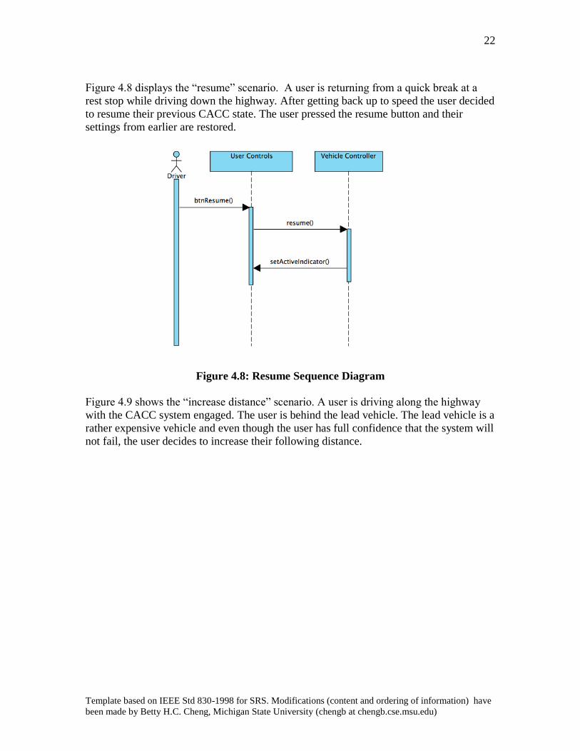
Figure 4.8 displays the “resume” scenario. A user is returning from a quick break at a
rest stop while driving down the highway. After getting back up to speed the user decided
to resume their previous CACC state. The user pressed the resume button and their
settings from earlier are restored.
Figure 4.8: Resume Sequence Diagram
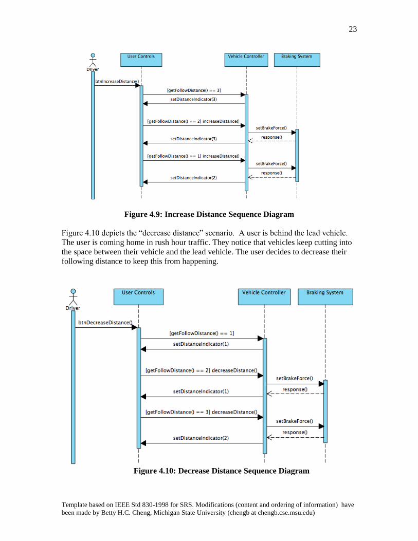
Figure 4.9 shows the “increase distance” scenario. A user is driving along the highway
with the CACC system engaged. The user is behind the lead vehicle. The lead vehicle is a
rather expensive vehicle and even though the user has full confidence that the system will
not fail, the user decides to increase their following distance.
23
Template based on IEEE Std 830-1998 for SRS. Modifications (content and ordering of information) have
been made by Betty H.C. Cheng, Michigan State University (chengb at chengb.cse.msu.edu)
Figure 4.9: Increase Distance Sequence Diagram
Figure 4.10 depicts the “decrease distance” scenario. A user is behind the lead vehicle.
The user is coming home in rush hour traffic. They notice that vehicles keep cutting into
the space between their vehicle and the lead vehicle. The user decides to decrease their
following distance to keep this from happening.
Figure 4.10: Decrease Distance Sequence Diagram
24
Template based on IEEE Std 830-1998 for SRS. Modifications (content and ordering of information) have
been made by Betty H.C. Cheng, Michigan State University (chengb at chengb.cse.msu.edu)
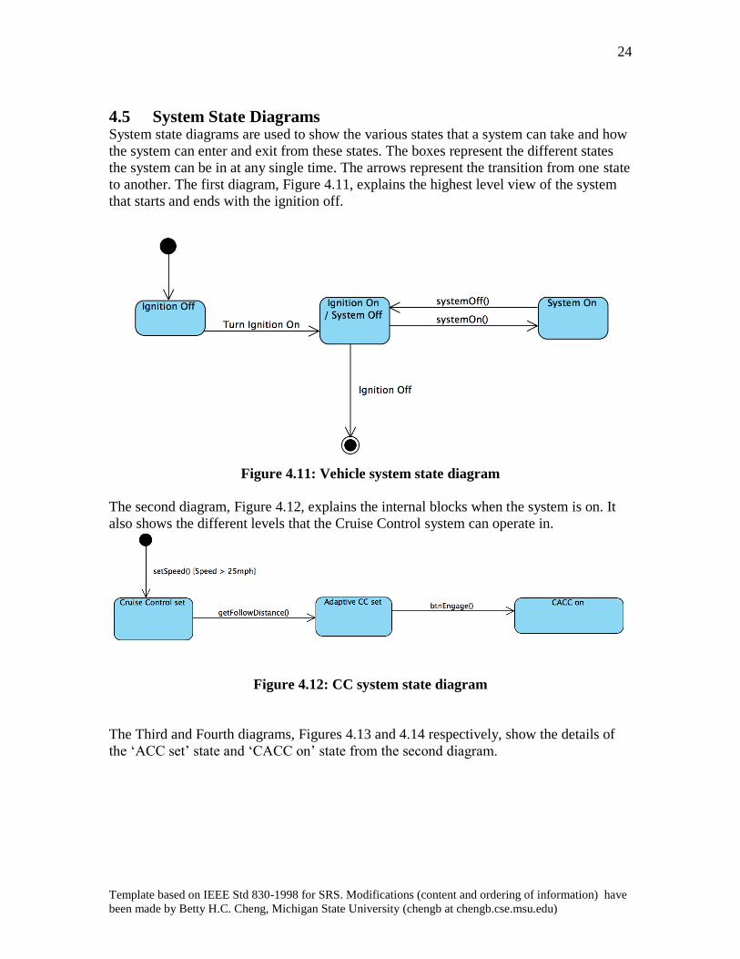
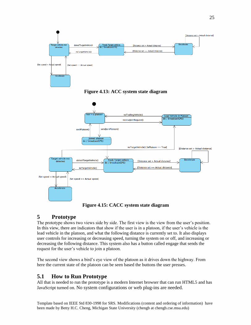
4.5 System State Diagrams
System state diagrams are used to show the various states that a system can take and how
the system can enter and exit from these states. The boxes represent the different states
the system can be in at any single time. The arrows represent the transition from one state
to another. The first diagram, Figure 4.11, explains the highest level view of the system
that starts and ends with the ignition off.
Figure 4.11: Vehicle system state diagram
The second diagram, Figure 4.12, explains the internal blocks when the system is on. It
also shows the different levels that the Cruise Control system can operate in.
Figure 4.12: CC system state diagram
The Third and Fourth diagrams, Figures 4.13 and 4.14 respectively, show the details of
the ‘ACC set’ state and ‘CACC on’ state from the second diagram.
25
Template based on IEEE Std 830-1998 for SRS. Modifications (content and ordering of information) have
been made by Betty H.C. Cheng, Michigan State University (chengb at chengb.cse.msu.edu)
Figure 4.13: ACC system state diagram
Figure 4.15: CACC system state diagram
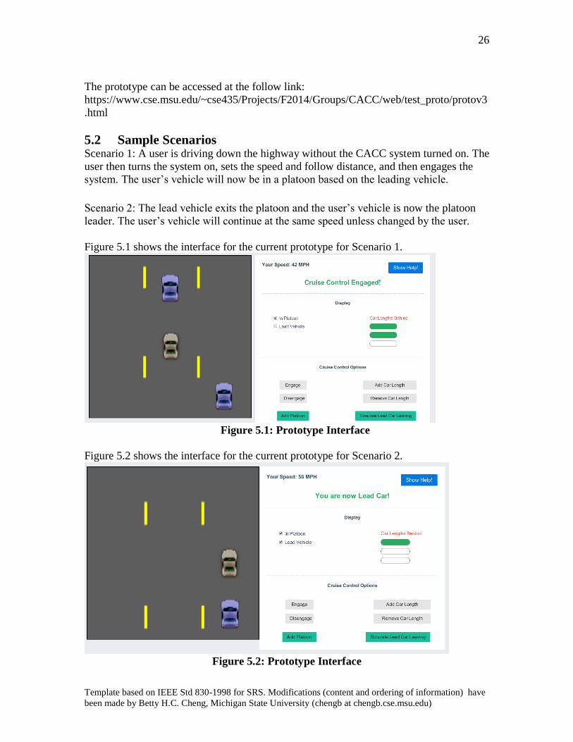
5 Prototype The prototype shows two views side by side. The first view is the view from the user’s position.
In this view, there are indicators that show if the user is in a platoon, if the user’s vehicle is the
lead vehicle in the platoon, and what the following distance is currently set to. It also displays
user controls for increasing or decreasing speed, turning the system on or off, and increasing or
decreasing the following distance. This system also has a button called engage that sends the
request for the user’s vehicle to join a platoon. The second view shows a bird’s eye view of the platoon as it drives down the highway. From
here the current state of the platoon can be seen based the buttons the user presses.
5.1 How to Run Prototype All that is needed to run the prototype is a modern Internet browser that can run HTML5 and has
JavaScript turned on. No system configurations or web plug-ins are needed.
26
Template based on IEEE Std 830-1998 for SRS. Modifications (content and ordering of information) have
been made by Betty H.C. Cheng, Michigan State University (chengb at chengb.cse.msu.edu)
The prototype can be accessed at the follow link:
https://www.cse.msu.edu/~cse435/Projects/F2014/Groups/CACC/web/test_proto/protov3
.html
5.2 Sample Scenarios
Scenario 1: A user is driving down the highway without the CACC system turned on. The
user then turns the system on, sets the speed and follow distance, and then engages the
system. The user’s vehicle will now be in a platoon based on the leading vehicle.
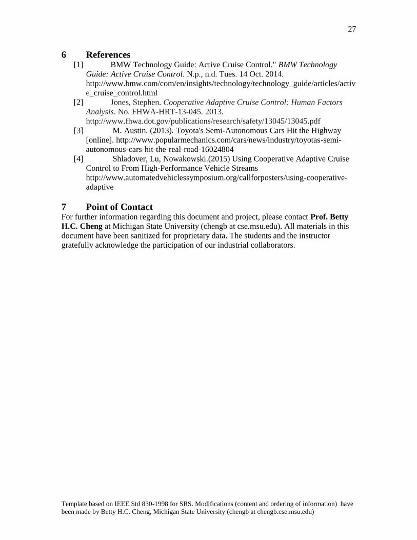
Scenario 2: The lead vehicle exits the platoon and the user’s vehicle is now the platoon
leader. The user’s vehicle will continue at the same speed unless changed by the user.
Figure 5.1 shows the interface for the current prototype for Scenario 1.
Figure 5.1: Prototype Interface
Figure 5.2 shows the interface for the current prototype for Scenario 2.
Figure 5.2: Prototype Interface
27
Template based on IEEE Std 830-1998 for SRS. Modifications (content and ordering of information) have
been made by Betty H.C. Cheng, Michigan State University (chengb at chengb.cse.msu.edu)
6 References
[1] BMW Technology Guide: Active Cruise Control." BMW Technology
Guide: Active Cruise Control. N.p., n.d. Tues. 14 Oct. 2014.
http://www.bmw.com/com/en/insights/technology/technology_guide/articles/activ
e_cruise_control.html
[2] Jones, Stephen. Cooperative Adaptive Cruise Control: Human Factors
Analysis. No. FHWA-HRT-13-045. 2013.
http://www.fhwa.dot.gov/publications/research/safety/13045/13045.pdf
[3] M. Austin. (2013). Toyota's Semi-Autonomous Cars Hit the Highway
[online]. http://www.popularmechanics.com/cars/news/industry/toyotas-semi-
autonomous-cars-hit-the-real-road-16024804
[4] Shladover, Lu, Nowakowski.(2015) Using Cooperative Adaptive Cruise
Control to From High-Performance Vehicle Streams
http://www.automatedvehiclessymposium.org/callforposters/using-cooperative-
adaptive
7 Point of Contact
For further information regarding this document and project, please contact Prof. Betty
H.C. Cheng at Michigan State University (chengb at cse.msu.edu). All materials in this
document have been sanitized for proprietary data. The students and the instructor
gratefully acknowledge the participation of our industrial collaborators.