Software Performance Analysis - Queen's...
58
Software Performance Analysis UML Tutorial SOFT 437
Transcript of Software Performance Analysis - Queen's...

Software Performance Analysis
UML Tutorial
SOFT 437
SOFT 437 2
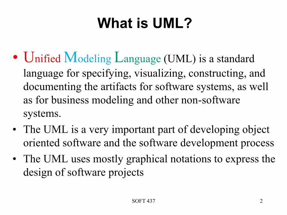
What is UML?
• Unified Modeling Language (UML) is a standard
language for specifying, visualizing, constructing, and
documenting the artifacts for software systems, as well
as for business modeling and other non-software
systems.
• The UML is a very important part of developing object
oriented software and the software development process
• The UML uses mostly graphical notations to express the
design of software projects

UML Tools
• Standalone tools
– Web-based tools (e.g., creatly.com)
– Packages (e.g., ArgoUML)
• Plugin tools
– Integrate with IDEs (e.g., UML2-SDK for Eclipse)
• Tutorials
– Many many tutorials online
SOFT 437 3

UML Building Blocks
SOFT 437 4
• Things – Structural Behavioral
– Grouping Annotational
• Relationships
• Diagrams
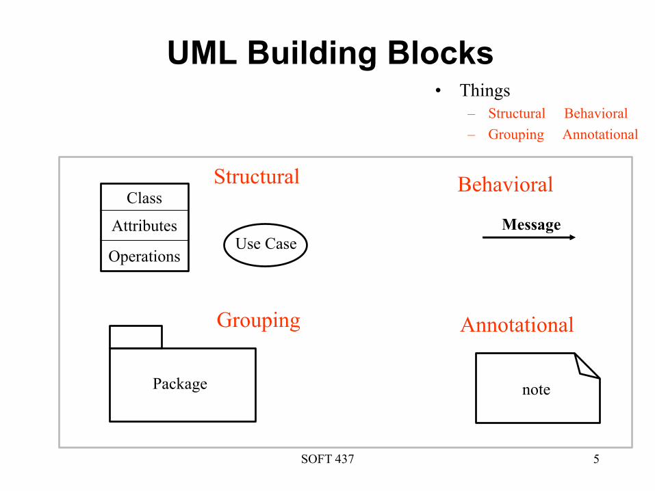
UML Building Blocks
SOFT 437 5
• Things
– Structural Behavioral
– Grouping Annotational
Message
Use Case
Class
Attributes
Operations
Package note
Structural
Grouping
Behavioral
Annotational
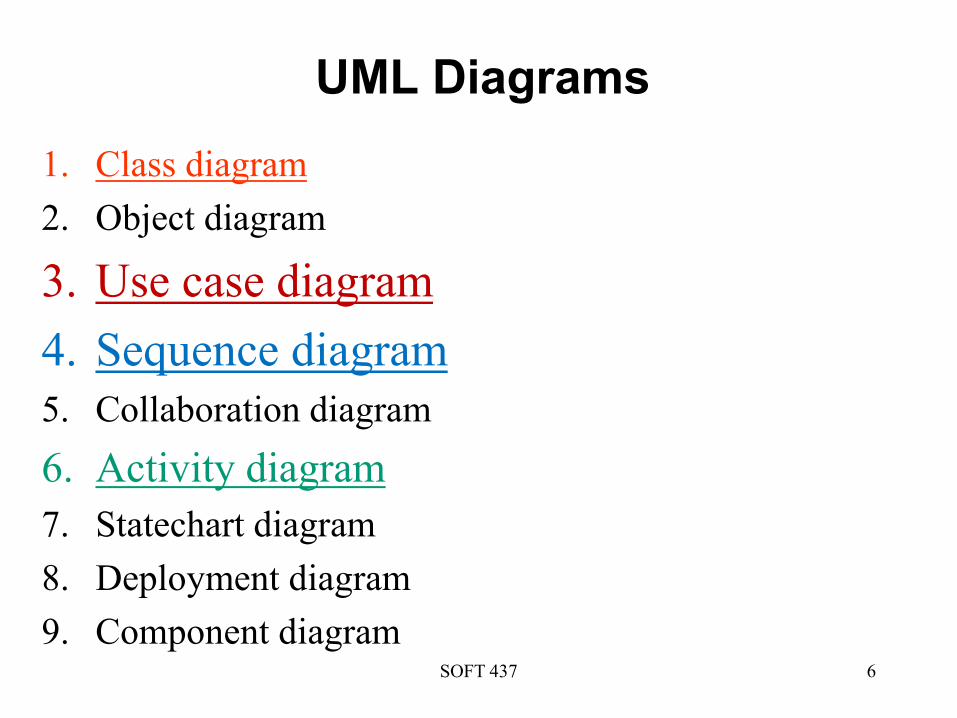
UML Diagrams
1. Class diagram
2. Object diagram
3. Use case diagram
4. Sequence diagram
5. Collaboration diagram
6. Activity diagram
7. Statechart diagram
8. Deployment diagram
9. Component diagramSOFT 437 6

SOFT 437 7
Class Diagrams
• Classes are composed of three components: a
name, attributes, and operations.
SOFT 437 8
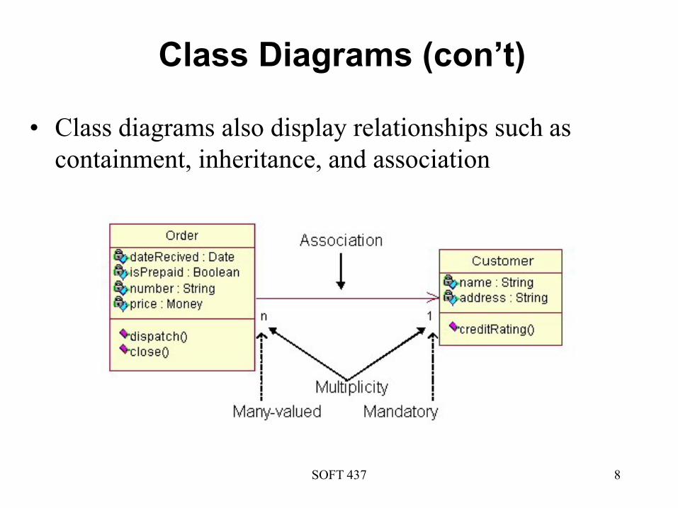
Class Diagrams (con’t)
• Class diagrams also display relationships such as
containment, inheritance, and association
SOFT 437 9
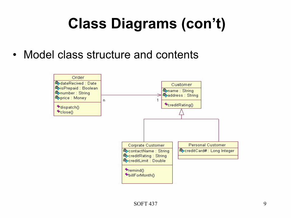
Class Diagrams (con’t)
• Model class structure and contents

SOFT 437 11
Use Cases
• Use cases describe the behavior of a system or a
subsystem
– A set of actions that a system performs and yields an
observable result of value to an actor
– An actor is an entity outside the system (e.g., a user or
another system) and interacts directly with the system
• A use case does not reveal internal details of interactions
between actors and the system

SOFT 437 12
Example Use Cases

SOFT 437 13
Use Case Diagrams
• A use case diagram shows
– a set of use cases,
– the actors that interact with use cases
– the relationships
• An actor can be represented by stick figures or stereotyped icons
• A use case is represented by an ellipse that contains the name of the use case
System
Boundary
Use Case
Association
Actor

SOFT 437 14
Critical Use Cases
• Use cases are employed to
– model the context of the system: the system boundary indicates which features are part of (inside) the system, which actors interact with system, and the meaning of interaction
– specify the requirements for the system (i.e., what the system should do from the point of view of actors)
• From a performance point of view, use case diagrams are used to identify the critical functions of the system that are most important to performance
• The critical use cases are considered, including
– are critical to the operation of the system
– influence users’ perception of responsiveness
– represent a risk that performance goals might not be met

SOFT 437 15
Use Cases and Scenarios
• The SPE process focuses on use cases and the scenarios
that describe them
• By examining the system’s use cases, you can identify
the functions of the system that are significant to
performance
• A scenario is an instance of a use case
• Performance scenario are the scenarios that have the
most impact on performance

SOFT 437 16
Scenarios
• A scenario is an instance of a use case
• It consists of a sequence of steps describing the
interactions between the objects involved in a particular
execution of the software
• The scenario shows
– objects that participate
– messages (e.g., event or method invocation) that flow
between them

SOFT 437 17
Scenarios (cont.)
• Scenarios are represented by either sequence diagrams
or collaboration diagrams
• Sequence diagrams emphasize the time-ordering of
message
• Collaboration diagrams emphasize the structural
organization of the collection of interacting objects
• Sequence diagrams are more natural to use for
constructing performance models

SOFT 437 18
Sequence Diagrams
• Sequence diagrams demonstrate the behaviour of
objects in a use case by describing the objects and the
messages they pass.
Lifeline
notation
Activation

SOFT 437 19
Sequence Diagrams (con’t)
Destroy Object

SOFT 437 20
Creation and Destruction
• An activation indicates a period of time when the object is busy performing some action
• Object creation and destruction are indicated by the stereotyped messages
Activation:
focus of control
Object creation
Object
Destruction
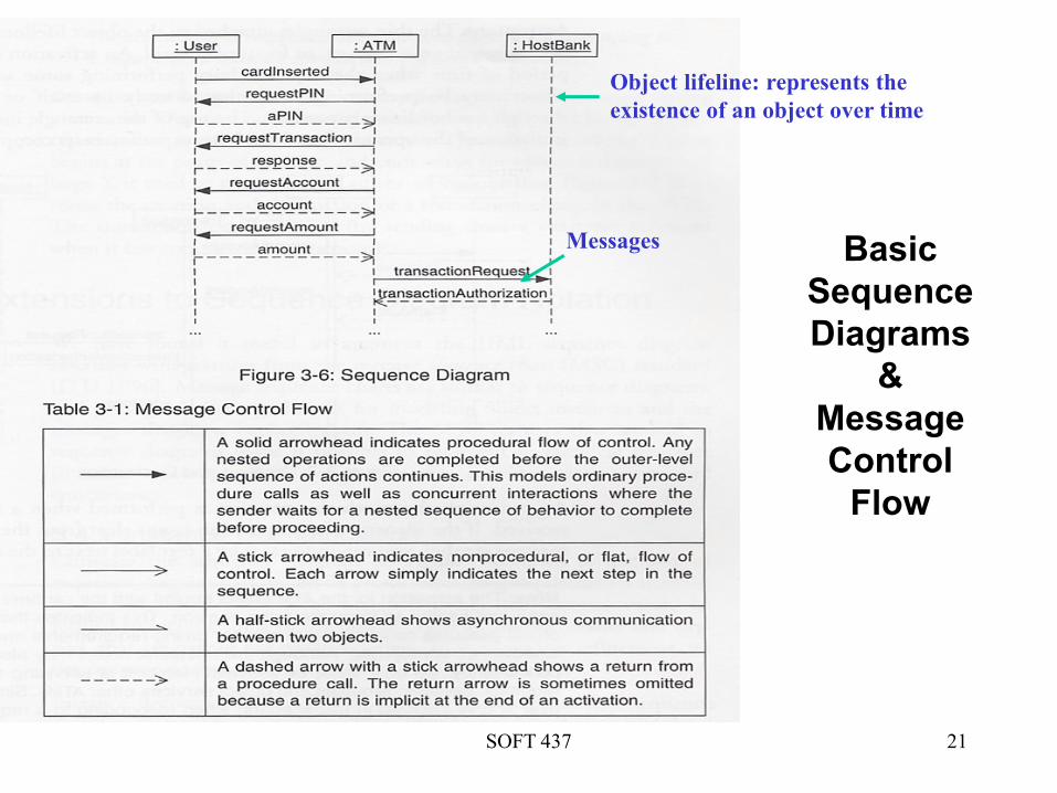
SOFT 437 21
Basic
Sequence
Diagrams
&
Message
Control
Flow
• Figure 3-6
Object lifeline: represents the
existence of an object over time
Messages

SOFT 437 22
Activity Diagrams
• Show the flow of
activities through the
system
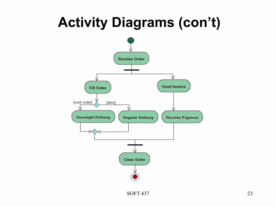
SOFT 437 23
Activity Diagrams (con’t)

Quick Quiz
SOFT 437 24
System
Boundary
Use Case
Association
Actor
1
2
3
4

Quick Quiz (cont.)
SOFT 437 25
Lifeline
notation
Activation
Class
Destroy Object
1
2
3
4

Software Performance Analysis
Chapter 3: SPE and the UML
SOFT 437

SOFT 437 27
Extending the UML
• UML provides built-in extension mechanisms that allow
you to tailor the notation for particular purposes.
• These mechanisms are
– stereotypes
– tagged values
– constraints
SOFT 437 28
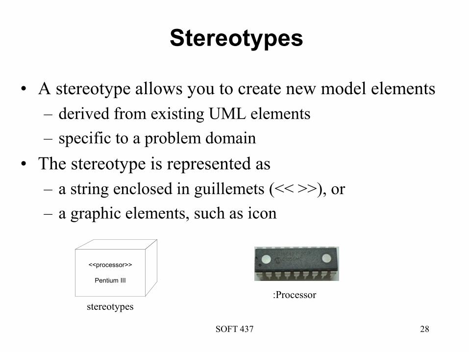
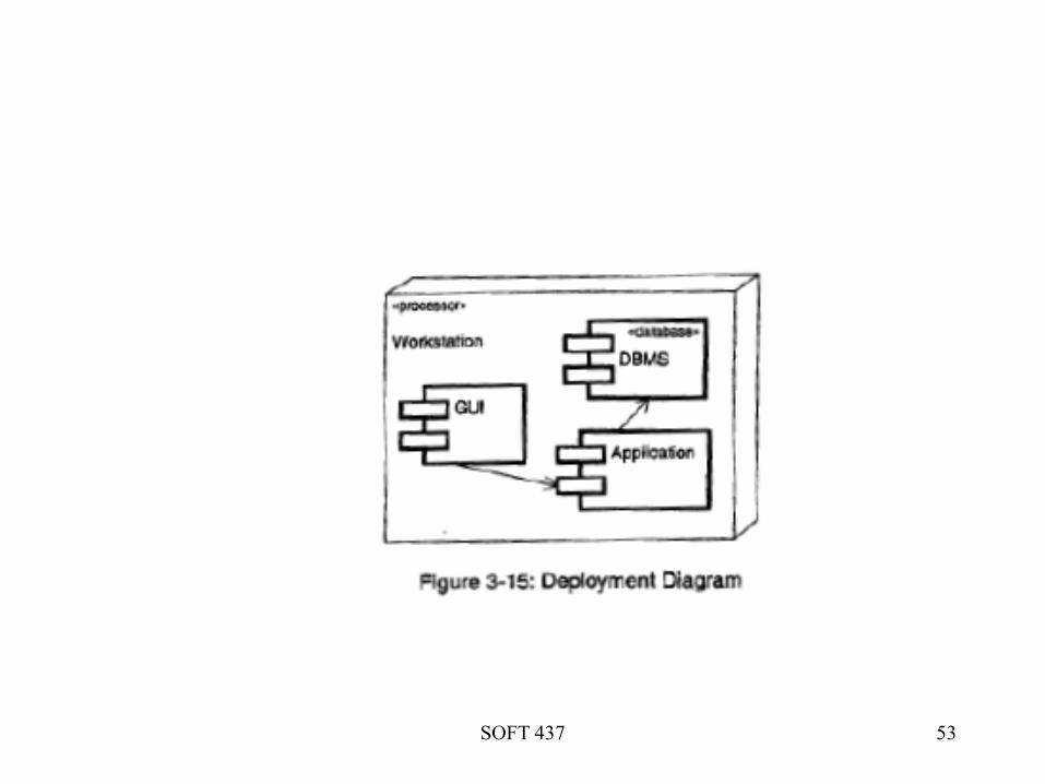
Stereotypes
• A stereotype allows you to create new model elements
– derived from existing UML elements
– specific to a problem domain
• The stereotype is represented as
– a string enclosed in guillemets (<< >>), or
– a graphic elements, such as icon
<<processor>>
Pentium III
stereotypes:Processor

SOFT 437 29
Tagged Values
• A tagged value allows you to include new properties for
model elements
• A tagged value is a pair of strings -- a tag and a value
– {name of a property = value of the property}
Client
{processorSpeed=500MHZ}
Tagged Values

SOFT 437 30
Constraints
• A constraint is a condition or restriction that defines
additional model semantics
• A constraint may be attached to an individual model
element or a collection of elements
• A constraint is written as a string enclosed in braces ({})
Constraints
SOFT 437 31
Stereotypes, Tagged Values,
Constraints
• We use stereotypes and tagged values to capture
information about the software execution environment
– e.g., processor type, processor speed, network speed
• We use constraints to specify performance objectives
– e.g., response time or throughput

SOFT 437 32
Extensions to Sequence Diagram
Notation• Sequence diagram notation is extended to represent
– hierarchical structure (instance decomposition and
references)
– looping
– alternation
– concurrency

SOFT 437 33

SOFT 437 34
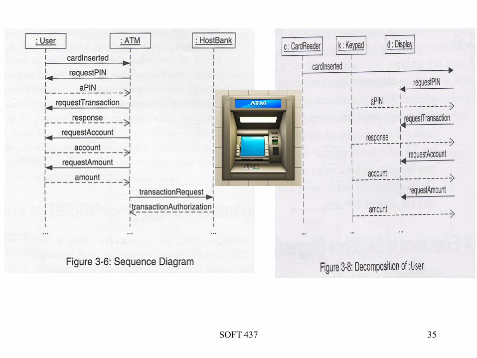
Instance Decomposition
• Uses instance decomposition to indicate the refinement
of sequence diagrams
• Makes it possible to attach another sequence diagram to
an object lifeline
• Allows expansion of a high-level sequence diagram to
show lower-level interactions
SOFT 437 35

SOFT 437 36
ATTENTION!
For the decomposition to be meaningful, the order of
messages on the decomposed instance must be preserved
SOFT 437 38
Benefits of Instance Decomposition
• Elaborate the sequence diagram as we learn more about
the system, without having to re-draw the diagram each
time
• Ensure the consistency with the scenario as it was
originally described
Use instance decomposition to elaborate high-level
objects as the design evolves

SOFT 437 39
Loop and Alternation
Repetition
Alternation
(choice)
SOFT 437 40
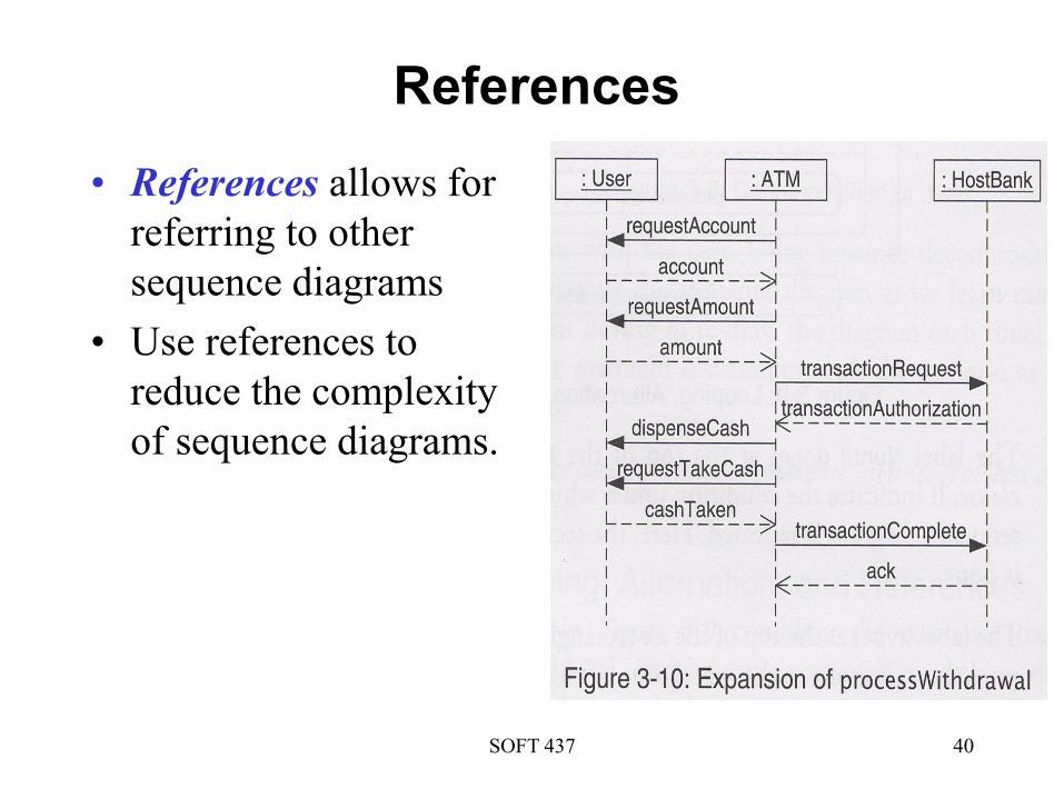
References
• References allows for
referring to other
sequence diagrams
• Use references to
reduce the complexity
of sequence diagrams.

SOFT 437 41
Loop and Alternation (con’t)
• Loop can be used when a sequence is repeated
• Alternation can be used when several possible
transitions will be executed
• A probability of execution can be attached to a given
sequence
while, loop, etc.
If-then, switch-case, etc.
Probability

SOFT 437 42
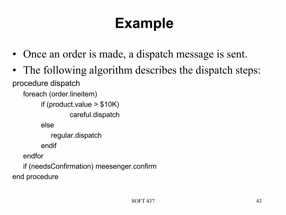
Example
• Once an order is made, a dispatch message is sent.
• The following algorithm describes the dispatch steps:procedure dispatch
foreach (order.lineitem)
if (product.value > $10K)
careful.dispatch
else
regular.dispatch
endif
endfor
if (needsConfirmation) meesenger.confirm
end procedure
SOFT 437 43

SOFT 437 44

SOFT 437 45
Specifying Time
• The UML allows you to specify timing requirements
through the use of
– timing marks
– time expressions
– timing constraints

SOFT 437 46
Timing Marks
• Denote the time at which a message or an event occurs
• For example:
– message.sendTime() -- The time that the message is sent
– message.recieveTime() -- The time that the message is
received
– where message is the name of the message
SOFT 437 47
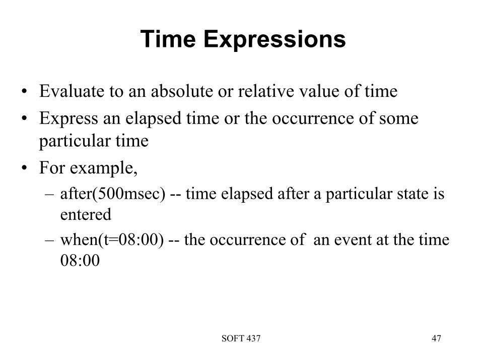
Time Expressions
• Evaluate to an absolute or relative value of time
• Express an elapsed time or the occurrence of some
particular time
• For example,
– after(500msec) -- time elapsed after a particular state is
entered
– when(t=08:00) -- the occurrence of an event at the time
08:00
SOFT 437 48
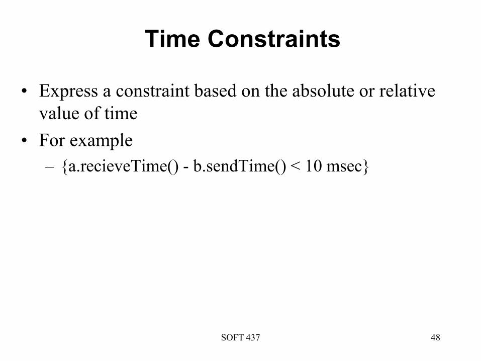
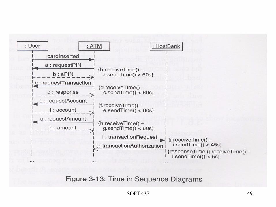
Time Constraints
• Express a constraint based on the absolute or relative
value of time
• For example
– {a.recieveTime() - b.sendTime() < 10 msec}
SOFT 437 49

SOFT 437 50
Time Constraints (con’t)
• Timeout conditions are not particularly useful from a
performance perspective
• When specifying performance, we are more interested in
response time
– responseTime(j.receiveTime() – i.sendTime())
– {responseTime(j.receiveTime() – i.sendTime()) < 5s} – a
time constraint example
Use time expressions that are meaningful from a
performance perspective, such as responseTime(), to
specify performance objectives
SOFT 437 51
Concurrency
• Modeling concurrency is important in the later stages of
SPE for evaluating contention effects
• Concurrency issues are expressed by UML notations
– Threads and Processes
– Coregions
– Parallel Composition
– Synchronization
SOFT 437 52
Threads and Processes
• A process represents a flow of control that executes in
parallel with other processes
– Each process has its own address space
– represented by a standard stereotype <<process>>
• A thread executes concurrently with other threads inside
a process
– all threads belonging to a process all share the same
address space
– represented by a standard stereotype <<thread>>
SOFT 437 53

SOFT 437 54
Coregions
• A sequence diagram are
strictly ordered in time
• Coregions allow an
exception to total ordering
whereby messages within a
coregion are unordered
• Coregions allow you to
show the interleaving of
messages that occur in
parallel processing
Coregion
Coregion
{represented by a solid line with horizontal dividers}

SOFT 437 55
Parallel Composition
• Indicates sections of the sequence diagram that are
executed in parallel
• Shows the interleaving of messages that occur in
parallel processing
• Allows more flexible representation of parallel
processing
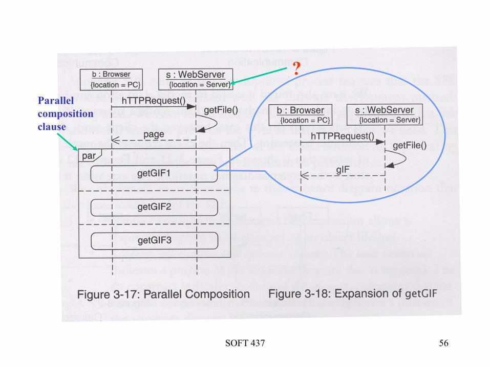
SOFT 437 56
Parallel
composition
clause
?
SOFT 437 57
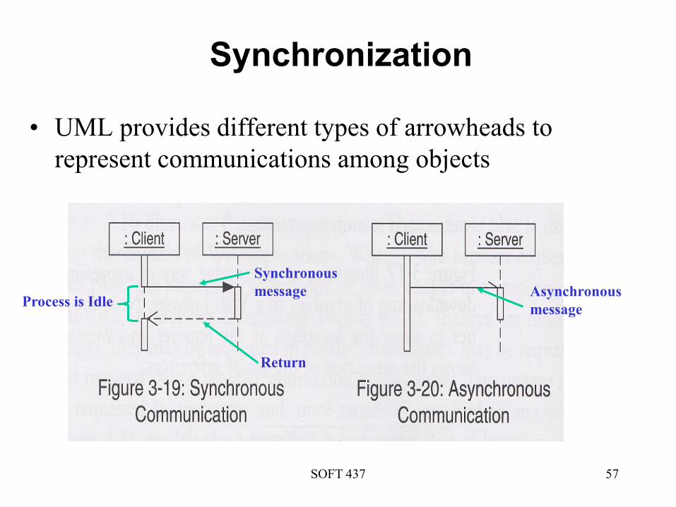
Synchronization
• UML provides different types of arrowheads to
represent communications among objects
Synchronous
message
Return
Asynchronous
messageProcess is Idle

SOFT 437 58
Synchronization (con’t)
SOFT 437 59
Contention Effects
• Modeling concurrency is important in the later stages of
SPE for evaluating contention effects
• Early stages of the development process focus on
software model without contention
• Concurrency and synchronization properties of the
proposed software are considered later when your
knowledge of the software system increases

SOFT 437 60
References
• Lecture notes for CS399 by Bob Dugan at stonehill university