Software for miniHV - Nikhef€¢ +12V, -12V and +60V power for the module(s) is supplied via the...
46
miniHV software v1.2 23-Aug-2011 1 Software for miniHV a high-voltage powersupply module with CANopen interface user manual & reference version 1.2 Henk Boterenbrood NIKHEF, Amsterdam 23 August 2011
Transcript of Software for miniHV - Nikhef€¢ +12V, -12V and +60V power for the module(s) is supplied via the...

miniHV software v1.2 23-Aug-2011
1
Software for miniHV
a high-voltage powersupply module with CANopen interface
user manual & reference version 1.2
Henk Boterenbrood NIKHEF, Amsterdam
23 August 2011
miniHV software v1.2 23-Aug-2011
2
Contents 1 MINIHV SYSTEM OVERVIEW ................................................................................................................................... 3
2 MONITORING AND CONTROLLING A MODULE................................................................................................. 7
2.1 INTRODUCTION......................................................................................................................................... 7 2.2 SETTING THE OUTPUT VOLTAGE .............................................................................................................. 7 2.3 RAMPING THE OUTPUT VOLTAGE............................................................................................................. 8 2.4 SETTING CURRENT LIMITS ..................................................................................................................... 12 2.5 MONITORING THE MODULE.................................................................................................................... 12 2.6 THE CONTROL LOOP............................................................................................................................... 13
3 MODULE STATUS LEDS............................................................................................................................................ 15
4 UTILITY PROGRAMS ................................................................................................................................................ 16
4.1 MINIHVCONF: A MINIHV CONFIGURATION TOOL.................................................................................. 16 4.2 MINIHVMON: A MINIHV MONITOR & CONTROL TOOL.......................................................................... 17
5 LOW-LEVEL ACCESS TO ONBOARD DEVICES.................................................................................................. 18
5.1 ANALOG INPUTS ..................................................................................................................................... 18 5.1.1 ADC Configuration........................................................................................................................ 18 5.1.2 Readout by SDO ............................................................................................................................ 18 5.1.3 Readout by PDO ............................................................................................................................ 19
5.2 ANALOG OUTPUT ................................................................................................................................... 20 5.3 PWM OUTPUT........................................................................................................................................ 20 5.4 CAN CONTROLLER ................................................................................................................................ 20
6 STORING THE CONFIGURATION .......................................................................................................................... 21
7 CANOPEN APPLICATION INITIALISATION........................................................................................................ 22
8 CANOPEN NODE GUARDING AND LIFE GUARDING........................................................................................ 23
9 OBJECT DICTIONARY............................................................................................................................................... 25
10 EMERGENCY OBJECTS ............................................................................................................................................ 37
11 CALIBRATION PROCEDURE................................................................................................................................... 39
12 EEPROM MEMORY MAP .......................................................................................................................................... 45
REFERENCES ....................................................................................................................................................................... 46
Table 1. Document change record.
Version History Version Date Comments
1.2 23 August 2011 Applies to MiniHV module firmware version 2.3.1 (2.3.2): added a picture of the new powersupply module, changes in calibration procedure, output voltage readout in units of 0.1V (instead of 1V).
1.1 31 May 2011 Applies to MiniHV module firmware version 2.2.7.
1.0 17 Feb 2011
Applies to MiniHV module firmware version 2.2.3: added Emergency indicating the PWM is off; added sections on utility programs MiniHVconf and MiniHVmon; added bits to TPDO1 indicat-ing ramp-in-progress and bleeder voltage; updated the references; several minor changes to text.
0.0 25 Jan 2011 Applies to MiniHV module firmware version 2.2.0.

miniHV software v1.2 23-Aug-2011
3
1 miniHV System Overview The miniHV low-current high-voltage powersupply module is a CAN-bus controlled pow-
ersupply with an output voltage range from 0 V to just over 1000 V (development of higher voltage versions are under consideration) and a current output of up to 1 μA, in a relatively small box (dimensions W x H x D = 108 mm x 82 mm x 43 mm), shown in Figure 1.
Each module has been individually calibrated to provide voltage output in Volt and output current in Ampere.
Features of the miniHV powersupply include:
• output voltage from 0 to 1000 V (a maximum allowed voltage can be configured up to about 1040 V)
• configurable voltage ramp-up speed with optional slow (exponentially de-pendent on time) approach of the end value
• choice between explicit voltage ramp-down or direct setting to lower voltage • output voltage is automatically regulated to compensate for variations in
the current load, with an absolute precision of ca. ±5V • output current and current readings up to 5 μA with pA resolution, and an
absolute precision of ca. ±1nA • configurable warning and trip limits for the high-voltage output current • bleeder resistor • three LEDs (green/red/yellow) indicating the status of the module and
high-voltage • LED indication warning for residual high voltage >50V on the output,
when the internal high-voltage generator is switched off (provided the bleeder resistor is installed)
• onboard temperature sensor, read-out in (milli)degrees centigrade • remote control and monitoring via CAN bus (up to about 100 m distance) • easy daisy-chaining of multiple modules using standard 8-wire ethernet
cables with RJ45 connectors • possibility to connect and control dozens of modules on the same CAN
bus from one host computer • +12V, -12V and +60V power for the module(s) is supplied via the CAN
bus cable (typical current drawn: 30 mA, 20 mA and 7 mA resp.)

miniHV software v1.2 23-Aug-2011
4
Figure 1. The miniHV high-voltage powersupply module. The RJ45 plugs carry the CAN-bus lines and power for the module and high-voltage generation. The module has two of these connectors for daisy-chaining multiple miniHV mod-ules.
The components of a miniHV system are shown in Figure 2. A minimal system consists of:
• one or more miniHV modules, • two miniHV CAN bus terminators, • a miniHV powersupply unit, interfacing +/-12V and +60V supplies to the CAN-bus
cable, • a 24V net adapter to power the powersupply unit.
In addition a number of standard ethernet-type network cables is required to connect the
miniHV modules, terminators and powersupply unit, as well as a single standard CAN cable with D9 connectors (one end male, one end female) to make the connection between the pow-ersupply unit and the CAN interface in the host computer. The provided software tools sup-port National Instruments and Kvaser CAN interfaces under Windows, and –optionally– Kvaser interfaces under Linux. A typical setup with multiple miniHV modules in shown schematically in Figure 3. Note
that the powersupply unit features a D9-connector for the CAN-bus connector to the host computer and two RJ45 connectors for two branches of the same CAN-bus. Each branch must be terminated with the provided miniHV CAN-bus terminator (equipped with RJ45 connec-tor, and integrated green LED). Each miniHV module on a single CAN-bus must have a unique CAN node identifier (indicated by a front-panel label; is however configurable).
Status LEDs High-voltage
output connector
Two RJ45 connectors for CAN busand power
Space for label with CAN node identifier (for now: address = serial nr)
Label with module serial number

miniHV software v1.2 23-Aug-2011
5
Figure 2. The miniHV system components. NB: the powersupply unit has been redesigned to connect directly to a power outlet and to not require a 24V net adapter (see Figure 4, picture on right), for reasons of improved grounding.
Figure 3. A miniHV system setup with multiple high-voltage modules, in two branches each terminated with a miniHV CAN-bus terminator.
24V net adapter
miniHV powersupply unit (+12V, -12V, +60V)
miniHV CAN bus
terminator
miniHV high-voltage module
CAN bus @ 125 kbit/s + power
PC + CAN-interface
Powersupply unit

miniHV software v1.2 23-Aug-2011
6
If a terminator is unplugged (or the CAN-bus line interrupted anywhere along the bus) the
60V auxiliary supply of the miniHV powersupply unit is automatically switched off, causing the high-voltage generators in all connected miniHV modules to switch off. Two red LEDs next to the RJ45 connectors on the powersupply unit indicate in which of the branches the ter-minator is missing, as illustrated in Figure 4 below. The digital electronics in the miniHV modules, powered by the +/-12V supplies keep on working, so communication with the mod-ule is not interrupted in any way.
Figure 4. Left picture: miniHV powersupply unit frontpanel, showing incomplete and/or unterminated CAN bus branches indicated by the red ‘error’ LEDs being on, and the 60V supply which is off due to this, indicated by the green ‘+60V’ LED being off. Right picture: frontpanel of the new miniHV powersupply unit, featuring a direct connection to a net power outlet.
Internally the miniHV high-voltage module consists of a controller board and a Cockcroft-
Walton (CW) high-voltage generator board. The CW board is equipped with a chip with a unique identifier (ID). The calibration constants stored in the miniHV module (on the con-troller board) are tied to a particular pair of the controller and CW boards. So the CW board cannot simply be exchanged: the module would have to be recalibrated. At power-up the software in the module checks whether the ID of the installed CW board matches the stored calibration constants and if this is not the case, will notify the user by means of a message and a status LED (see section 3).
More information about the miniHV hardware can be found in a separate document: see [1].
miniHV software v1.2 23-Aug-2011
7
2 Monitoring and Controlling a Module
2.1 Introduction
The processor controlling the miniHV module is an AT90CAN64 microcontroller with in-tegrated CAN controller [3]. In combination with an ADC device (Cirrus Logic CS5524 24-bit ADC [4]), a DAC device (Maxim MAX5544 14-bit DAC) as well as the AT90CAN64 on-chip 10-bit ADC and a PWM output, the microcontroller controls and monitors a multiple-stage Cockcroft-Walton voltage multiplier located on the CW board which generates the high-voltage. Communication with the firmware in the controller takes place via a CAN bus using the high-level CANopen protocol [2]. It is assumed the reader has at least a basic knowledge of the CANopen protocol.
The rest of this document describes how to interact with the miniHV module at the
CANopen level and includes a complete listing of its so-called Object Dictionary (OD), allow-ing access to all the module’s parameters, settings and over-all configuration. The complete OD is listed in section 9. In the rest of this document when referring to the embedded application software executed
by the microcontroller in the miniHV module the name MiniHV (underlined) is used to dis-tinguish it from the miniHV module hardware. Errors, faults and other events out of the ordinary are reported by MiniHV by means of
Emergency messages. A list of possible Emergency messages generated by MiniHV can be found in section 10.
2.2 Setting the Output Voltage The high-voltage output level can be set individually on each miniHV module, or can be
broadcast to all modules on the CAN bus. Depending on the configuration settings MiniHV will start ramping the output up to the requested value. Details on the ramping procedure can be found in the next section. The high-voltage output can be set by writing to OD index 2000h, subindex 1 or 2, using
CANopen SDO messages. The first subindex applies the ramping procedure (if configured) to both up- and down-ramping, the second subindex only to ramp-up (when the voltage is set to a lower value than the current value it is done immediately, without any explicit ramping).
The analog output can also be written using the CANopen PDO mechanism, which uses an
unconfirmed message with data without protocol overhead. The CAN-identifier used for this PDO is the so-called 2nd-receive-PDO (RPDO2) of the CANopen Predefined Connection i.e. COB-ID = 300h + NodeID. RPDO2 has 2 data bytes containing the requested voltage output level:

miniHV software v1.2 23-Aug-2011
8
Host → MiniHV RPDO2 COB-ID DataByte 0 DataByte 1 300h + NodeID HV value (LSB) HV value (MSB)
In addition, a PDO almost identical to RPDO2 is defined allowing a broadcast of a voltage
output to all miniHV modules on the CAN bus. The only difference with RPDO2 is the COB-ID which is equal to 200h (i.e. the COB-ID has no dependency on NodeID).
Once MiniHV is put into state Operational it can receive PDO messages and on reception
will set the voltage output according to the values in the PDO’s data bytes. Again, depending on its configuration settings, MiniHV will ramp the voltage output (for settings communicated by PDO only up; down is set directly).
2.3 Ramping the Output Voltage By default, if MiniHV receives a message to change the output voltage setting, it applies the
setting immediately. However, MiniHV can be configured to ramp up (and down) the voltage to the requested value with a ramp speed which can be configured to any value. It can ramp the voltage in a linear fashion, so from start value to end value with a constant ramping speed, or it can ramp the final part according to an exponential function, decreasing the ramping speed gradually, the nearer the output voltage gets to its end value. The part of the ramp which is done in this exponential fashion is set as a percentage of the end value. In addition, a mini-mum ramp speed can be set for the final exponential part. The ramping function is implemented in terms of settings of the DAC device, which directly
controls the high-voltage output. When the switch-over from linear to exponential ramping at time t=0 takes place the DAC
setting is at D0 and there are still De counts to reach the DAC end value D0+De, so DAC set-ting D(t) as a a function of time can be expressed as:
D(t) = D0 + De * (1 – exp(–At)) with constant A chosen such that the ramp speed s(t) at t=0 is equal to the set ramp speed s0, in other words:
dD(t)/dt = s(t) = A*De*exp(-At) ⇒ s(0) = s0 = A*De ⇒ A = s0/De so the ramp speed as a function of time s(t) in the exponential phase of the ramp can be ex-pressed as:
s(t) = s0 * exp(–t * s0/De) A table of values for exp(–0.05*i) with 0 ≤ i ≤ 200 is used to implement the exponential ramp. The absolute minimum ramping speed is about one (1) DAC increment per second. How-
ever, a larger minimum ramping speed can be configured for the exponential part of the ramp-ing process to limit the duration of the final (slowest) part of the ramping process. MiniHV’s Object Dictionary provides a number of objects for controlling and configuring
the ramping procedure:
• Ramping speed in millivolts per second (OD index 2000h, sub 7) • Ramping speed in DAC counts per second (OD index 2500h, sub 2) • Pause / resume ramp (OD index 2500h, sub 3)

miniHV software v1.2 23-Aug-2011
9
• Percentage of final value where the linear ramp switches to exponential ramping (OD index 2500h, sub 4)
• Minimum ramp speed during exponential ramp in DAC counts per second (OD index 2500h, sub 5)
If ramping is enabled (if the ramp speed is set >0) the ramping procedure starts immediately
after a new voltage setting is made. Figures 5 to 9 provide illustrations of the ramping process as a function of time. The figures show horizontally the time in seconds, and vertically the set-ting of the miniHV module’s 14-bit DAC (maximum setting 16383), which directly translates to the generated high-voltage output. There is a dependency of the resulting output voltage on the current load, which is taken into account and compensated for by the MiniHV control loop, after the ramping procedure is finished; see section 2.6 for details. Note that the DAC value samples in the plots have been taken once per second, with the points connected by smooth lines, up to the first sample with the end value. In the implementation of the ramping procedure the output voltage is updated up to a maxi-
mum of 100 times a second. For example, if the ramp speed is 1000 DAC-counts/s MiniHV will do an increment of 10 DAC-counts every 10 ms. Figure 5 shows some ramp curves with a linear ramp from start to final setting, for a number
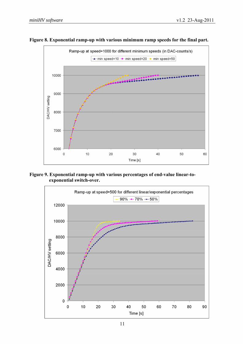
of different ramp speeds. Figure 6 shows some ramp curves with an exponential part that starts at 50% of the end value, for a number of different ramp speeds. Figure 7 shows some exponential ramps where the begin value is in the ‘middle’ of the exponential part of the ramp. Figure 8 shows the influence of different minimum ramp speeds on the shape of the ramp curve. Figure 9 does the same for a number of ‘percentage-of-end-value switch-over from linear to exponential’. The DAC setting was sampled once per second to obtain the plots.
Figure 5. Linear voltage ramp-up.

miniHV software v1.2 23-Aug-2011
10
Figure 6. Exponential voltage ramp-up with a minimum ramp speed of 10 (DAC counts).
Figure 7. Exponential ramp-up starting nearer to end value, so without initial linear part.
miniHV software v1.2 23-Aug-2011
11
Figure 8. Exponential ramp-up with various minimum ramp speeds for the final part.
Figure 9. Exponential ramp-up with various percentages of end-value linear-to-exponential switch-over.

miniHV software v1.2 23-Aug-2011
12
2.4 Setting Current Limits MiniHV provides two configurable output current limits: a warning limit and a trip limit.
The limits are set in units of nA, in OD index 2001h, sub 3 and 4 respectively. If a limit is set to 0, it is not checked against the actual output current. Checking the actual
current against the configured limits is done by the control loop, described in section 2.6. In addition a counter can be configured to count the number of consecutive exceedances of
the limit before taking action. This counter can be configured in OD index 2001h, sub 5; its default value is 1. Note that the time a limit is exceeded before action is taken by MiniHV de-pends on this counter as well as the control loop frequency. For example, if the counter is set to 10 and the control loop frequency is set to 2 Hz, the action taken as a result of a current limit exceedance is taken only after the exceedance persisted for at least 5 s.
When the warning limit (plus counter) is exceeded an Emergency message is sent; see sec-
tion 10. Note that a new Emergency message is sent only when the limit is exceeded after the current has first dropped again below the warning limit. When the trip limit (plus counter) is exceeded an Emergency message is sent, and the high-
voltage output is set to 0. The red ‘Error’ LED will start to blink. As soon as a new high-voltage setting is made by the user the error indication is removed.
2.5 Monitoring the Module Interaction with MiniHV can be done (almost) entirely based on CANopen SDO (Service
Data Object) messages, reading and/or writing directly from and to objects in the module’s OD, in particular Objecs 2000h (high-voltage, including temperature sensor reading and ramp speed in units of Volts), 2001h (high-voltage control loop) and 2500h (most ramping-related parameters).
A faster and easier way to read out some of the important parameters a user may wish to
monitor is to use a CANopen PDO (Process Data Object) message. A PDO message is a non-confirmed CAN-message with one sender and one or more receivers, containing no protocol overhead, only data (from 1 to 8 bytes). Receivers of a particular PDO message are supposed to know the meaning of the data content of the message. MiniHV supports 4 PDOs in total, three ‘transmit’ PDOs and one ‘receive’ PDO. Only the
PDO carrying the main high-voltage parameters is described here, as it is the only PDO of in-terest to the normal user (a description of the other PDOs can be found in section 5).

miniHV software v1.2 23-Aug-2011
13
By default MiniHV responds to a CANopen SYNC message by sending a PDO (the socalled
‘first transmit PDO’ or TPDO1) with the following content:
MiniHV → Host TPDO1 COB-ID DataByte 0-1 DataByte 2-5 DataByte 6-7
180h+NodeID output voltage output current bits 0-13: DAC value bit 14: bleeder voltage bit 15: ramping
with: output voltage: the output voltage in units of 0.1V, corresponding to OD entry 2000h,
sub 3, 2 bytes, LSB first, i.e. the output voltage according to a reading from a parallel Cockcroft-Walton stage, adjusted by a term which depends on the currently supplied current load (given by the next 4 bytes).
output current: the output current load in pA, corresponding to OD entry 2000h, sub 4, 4 bytes, LSB first,
DAC value: the currently set (14-bits) DAC value, corresponding to OD entry 6411h, sub 1, 2 bytes, LSB first,
bleeder voltage: a bit when set to 1 indicates that there is high-voltage output (detected through bleeder resistor current) eventhough the high-voltage setting is equal to 0 (zero); corresponds to OD entry 2000h, sub 5 exceeding 50V while OD entry 2000h, sub 1 equal to 0,
ramping: a bit when set to 1 indicates that the output voltage is ramping, corre-sponding to OD entry 2500h, sub 3.
Optionally DAC value can be replaced by a reading from the onboard temperature sensor,
in units of 0.1 degrees centigrade, by setting the object in OD index 2000h, sub 13 to 1 (= true). Optionally output voltage can be replaced by the voltage directly derived from a reading of
the bleeder current, by setting the object in OD index 2000h, sub 14 to 1 (= true). Note that this is a somewhat unreliable parameter due to the instability of the bleeder resistance value. Note that a SYNC message will trigger this reply from all miniHV modules connected to
the CAN bus, simplifying monitoring of multiple modules.
2.6 The Control Loop If the miniHV module has been calibrated (which normally is the case) MiniHV automati-
cally starts a control loop when the module is powered up, which does all of the following pe-riodically, with a configurable frequency:
• Initiates a regular sequence of ADC input conversions to regularly obtain a new set of input data samples used in the other tasks in this list.
• Regulates the setting of the DAC that drives the high-voltage generator to achieve the intended output voltage on the basis of the measured output current value, adjust-ing the DAC setting to compensate for the voltage drop due to this current. All the while the output voltage ramp configuration is taken into account when increasing or decreasing the DAC setting, including exponential ramp-up and minimum ramp-up speed. Alternatively, the DAC setting may be adjusted on the basis of the voltage
miniHV software v1.2 23-Aug-2011
14
output as calculated from the measured bleeder current. However, this is not recom-mended since it was found that the bleeder resistance value is quite unstable over time (probably depending on environmental circumstances like temperature and hu-midity).
• Checks the presence of the +60V supply, switches off the high-voltage when absent (as a backup procedure, since this operation is already taken care of by means of an interrupt routine triggered by a microcontroller interrupt line which is directly tied to the +60V supply), and sends an Emergency message when this happens.
• Checks the output voltage according to the measured bleeder current and in case the high-voltage setting is zero it indicates the presence of a voltage > 50V using the yellow ‘HV’ status LED (blinking it rapidly; see section 3).
• Checks the output current and indicates any ‘warning limit exceeded’ or ‘trip limit exceeded’ occurrences using the red ‘Error’ LED (in case of a trip) and by sending an Emergency message.
• Operates the yellow ‘HV’ status LED when high-voltage ramping is not in progress (during a ramp the ramping process operates the LED).
The control loop settings and the current warning and trip limits can be configured in OD in-
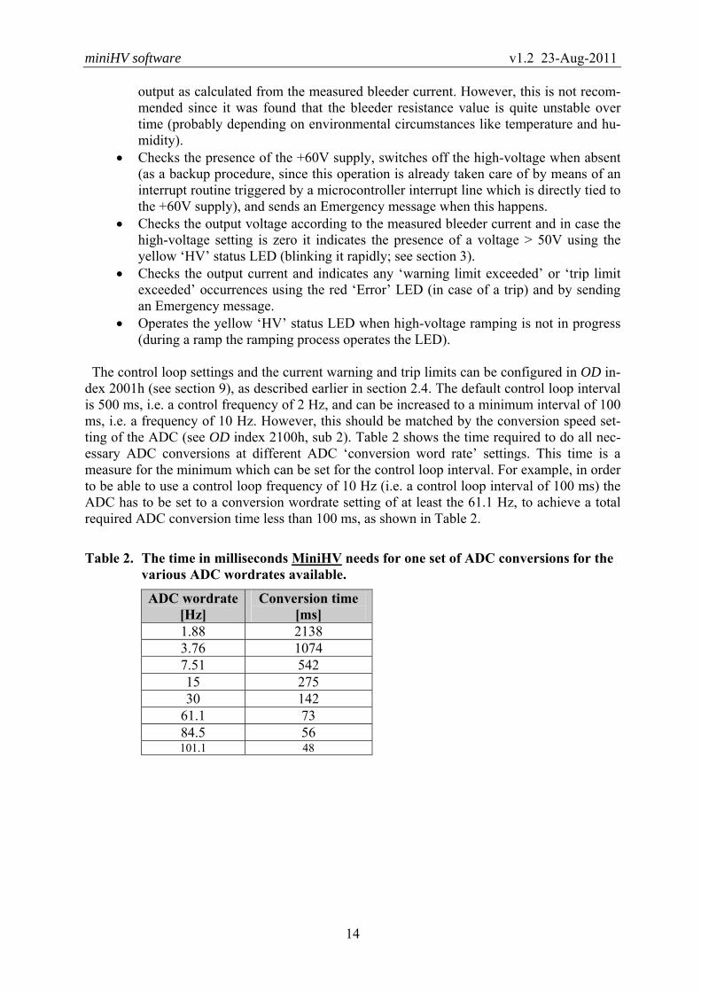
dex 2001h (see section 9), as described earlier in section 2.4. The default control loop interval is 500 ms, i.e. a control frequency of 2 Hz, and can be increased to a minimum interval of 100 ms, i.e. a frequency of 10 Hz. However, this should be matched by the conversion speed set-ting of the ADC (see OD index 2100h, sub 2). Table 2 shows the time required to do all nec-essary ADC conversions at different ADC ‘conversion word rate’ settings. This time is a measure for the minimum which can be set for the control loop interval. For example, in order to be able to use a control loop frequency of 10 Hz (i.e. a control loop interval of 100 ms) the ADC has to be set to a conversion wordrate setting of at least the 61.1 Hz, to achieve a total required ADC conversion time less than 100 ms, as shown in Table 2.
Table 2. The time in milliseconds MiniHV needs for one set of ADC conversions for the various ADC wordrates available.
ADC wordrate [Hz]
Conversion time [ms]
1.88 2138 3.76 1074 7.51 542 15 275 30 142
61.1 73 84.5 56 101.1 48

miniHV software v1.2 23-Aug-2011
15
3 Module Status LEDs
The miniHV module features three LEDs on its front-panel, indicating the status of the module: a green LED labeled ‘RUN/CAN’, a red LED labeled ‘ERROR’ and a yellow LED labeled ‘HV’, as shown in Figure 1.
The green LED is permanently on when the module has properly initialized and the firm-
ware is running. It blinks briefly when the module receives or sends CAN-messages. The red LED indicates whether an error of any sort has occurred. If there was an error de-
tected during a conversion of the onboard ADC (such as a time-out or an out-of-range read-ing) there is brief flash of the red LED (the flash is slightly longer for an ADC time-out).
If the high-voltage 60V generator supply is off the red LED blinks as long as this situation persists.
If the high-voltage output has been switched off due to exceeding a preset current limit (i.e the high-voltage tripped) the red LED blinks until a new high-voltage setting is made.
The yellow LED, when on, indicates that the high-voltage output is active, the frequency of
blinking indicating whether the voltage is ramping or has reached its intended setting. A blinking yellow LED may also indicate the high-voltage is in error state. This ‘HV error’
indication in combination with a blinking red LED means that the auxiliary +60V supply is off or the high-voltage has been switched off due to exceeding the set output current limit. In case the red LED is not on, the ‘HV error’ indication means that there is a problem with the calibration constants (missing, corrupted, or not matching with the installed CW board). The various patterns of blinking of the yellow LED produced by MiniHV are shown in some
more detail in Figure 10 below.
Figure 10. Blink patterns of the yellow ‘HV’ (high-voltage) status LED and a short de-scription of their meaning.
HV on and stable
HV error
HV is ramping, linear part
HV is ramping, final exponential part
Bleeder resistor indicates high-voltage (still) present
(but voltage generator is off)
Time →
Description Pattern

miniHV software v1.2 23-Aug-2011
16
4 Utility Programs
4.1 MiniHVconf: a MiniHV Configuration tool MiniHVconf is a utility program allowing a user to easily configure miniHV modules, in
particular the ramp procedure parameters and current limits. Figure 11 shows a representative screenshot of a configuration in progress. On opening a CAN port MiniHVconf scans the con-nected CAN bus for miniHV modules, which can then be individually selected from the Ad-dress drop-down menu item. After selecting a module some of its parameters and settings are read out and displayed. Some can then be modified (the valid range is indicated in a tool-tip; modified entries are indicated by a yellow background) and subsequently be saved onboard the module by clicking the Configure button (the yellow backgrounds disappear). As long as there is any input error (shown on a red background) the Configure button remains disabled, as shown in the screenshot. The Set Defaults button resets all MiniHV parameters back to their default values. As a bonus, the status of the currently selected module is continuously monitored and shown as a green or red ‘LED’ (marked Error Reg), depending on the mod-ule’s Error Register value (OD index 1002h).
Figure 11. Screenshot of the MiniHVconf program, showing a number of modified (but not saved yet) parameters (in yellow) and a parameter value modified but out-of-range (in red; in this case:‘Warning limit’ should be <=5000).

miniHV software v1.2 23-Aug-2011
17
4.2 MiniHVmon: a MiniHV Monitor & Control tool MiniHVmon is a utility program to allow a user to get started quickly with miniHV and to
control (i.e. set the output voltage) and monitor any number of miniHV modules connected to a CAN bus. For monitoring TPDO1 messages are used as described in section 2.5; periodi-cally (set by the Monitor interval spinbox) a CANopen SYNC message is sent by MiniHVmon to trigger all modules on the bus to send their data in a TPDO1 message. Voltage, current, temperature, (error) status and ramping-procedure-in-progress are monitored for all modules, but only for up to 4 of the modules these parameters are displayed in a MiniHV frame in the window, each one user-selectable by means of a drop-down menu. On opening a CAN port MiniHVmon automatically scans the connected CAN bus for miniHV modules.
The Ramping ‘LED’ blinks when the module is busy ramping its output voltage. The Status ‘LED’ turns red if a bit is set in the module’s Error Register (OD index 1002h); the Diagnos-tic Messages window will show a short description of the problem (also for modules that are not currently selected in the four MiniHV window frames). If the high-voltage output is active a yellow high-voltage icon appears in front of the voltage
parameter. The icon is also visible (and blinking) when there is residual output voltage >50V present (according to the measured bleeder current), eventhough the voltage shown may be zero. The output voltage can be set on each module individually (using the appropriate Set button),
or all modules can be set simultaneously using the Set All button. When entering a voltage value in an edit-box a validity check of the value is made; the box turns yellow when a new value is entered, and red when the entered value is out-of-range.
Figure 12. Screenshot of the MiniHVmon program.

miniHV software v1.2 23-Aug-2011
18
5 Low-level Access to Onboard Devices The access to devices on the miniHV module described in this chapter is meant for advanced
users and for test and debugging purposes.
5.1 Analog Inputs The analog inputs of MiniHV are used to read out the following parameters:
1. the high-voltage output voltage (although not corrected for the load (output) current), 2. the high-voltage output current, 3. the current through the bleeder resistor, 4. the onboard temperature sensor, 5. the high-voltage driver voltage, 6. the auxiliary supply (+60V) voltage.
5.1.1 ADC Configuration
The ADC configuration parameters, such as input voltage range and conversion speed, can be read from and set in OD index 2100h. However, input voltage range and unipolar/bipolar setting should not be changed as the module is made for and calibrated for a setting of 2.5V range bipolar. The conversion speed may be changed to allow for faster regulation of the out-put voltage (by software), as described elsewhere in this document.
In addition object 2100h allows to read from and to write to the ADC’s various registers,
primarily for test and debugging purposes.
5.1.2 Readout by SDO
The analog inputs can be read out using a CANopen SDO message, reading from OD index 6404h for readout of the ADC channels in ADC counts and from OD index 2400h for readout of the ADC channels in μV. Note that the data in these objects –apart from the ADC value– contain a 'flags' byte (read from the CS5524 Configuration Register), with a bit layout shown here:
BIT 7 6 5 4 3 2 1 0 Value 0 0 OF OD 0 0 0 0
with OD = Oscillation Detect Flag bit and OF = Over-range Flag bit. NB: stop the MiniHV control loop (OD index 2001h, sub 1) before reading analog inputs by
SDO, otherwise there is a good chance it will fail, when the loop is going through its own ADC conversions.

miniHV software v1.2 23-Aug-2011
19
5.1.3 Readout by PDO
If a PDO has been configured, MiniHV sends one PDO message for every analog input. It either sends PDO messages containing the raw ADC count or PDO messages containing the input voltage in microvolts (μV).
The CAN-identifier used for the ADC readout in counts is the so-called 2nd-transmit-PDO (TPDO2) of the CANopen Predefined Connection Set, i.e. COB-ID = 280h + NodeID.
The TPDO2 message is a 4-byte message and is formatted as follows:
MiniHV → Host TPDO2 COB-ID DataByte 0 DataByte 1 DataByte 2-4
280h+NodeID Channel Number Chan status ADC value with:
ADC value: 24-bits value, LSB in byte 2, MSB in byte 4. Channel Number: number 0-5. Chan status: bit 7: Conversion status: 1=ERROR (overflow or oscillation), 0=OKAY.
The CAN-identifier used for the ADC readout in μV is the so-called 3rd-transmit-PDO
(TPDO3) of the CANopen Predefined Connection Set, i.e. COB-ID = 380h + NodeID. The TPDO3 message is a 6-byte message and is formatted as follows:
MiniHV → Host TPDO3 COB-ID DataByte 0 DataByte 1 DataByte 2-5
380h+NodeID Channel Number Chan status ADC value [μV] with:
ADC value: 32-bits signed value in μV, LSB first. Channel Number: number 0-5. Chan status: see above.
The ADC resolution in μV depends on the ADC voltage range setting as set in OD index 2100h. The way in which the analog inputs are read out depends on the transmission-type of
TPDO2 and TPDO3. The analog input is read out according to the PDO transmission type af-ter power-up. Alternatively the user can set the transmission type to the required value by writing to MiniHV’s Object Dictionary (to OD index 1801h, sub 2 or OD index 1802h, sub 2), and possibly stores it permanently in onboard EEPROM so that it will be the default transmission type after every subsequent reset or power-up. The following modes of transmission are supported: • PDO transmission type 1:
after every so-called SYNC message issued on the CAN-bus, MiniHV sends a TPDO message as shown above for every ADC input channel. The SYNC message is a CAN-message with a fixed COB-ID and no data bytes:
Host → all (SYNC-)slave nodes COB-ID
080h

miniHV software v1.2 23-Aug-2011
20
Note that all nodes that have PDOs configured to respond to a SYNC message will re-spond to it (a SYNC is a broadcast message). Note also that if both TPDO2 and TPDO3 have transmission type 1 only TPDO3 mes-sages are produced.
• PDO transmission type 255 and Event Timer = 0:
after every so-called Remote Transmission Request (RTR, or Remote Frame) for TPDO2/3, MiniHV sends one TPDO2 or TPD3 message for every ADC input channel. The CAN Remote Frame that constitutes this RTR has no data bytes:
Host → MiniHV COB-ID
280h + NodeID Note that an RTR is sent to and processed by only one particular node.
• PDO transmission type 255 and Event Timer > 0:
If TPDO2’s event timer (OD index 1801h, sub 5) or TPDO3’s event timer (OD index 1802h, sub 5) is set to a value unequal to zero (event timer is expressed in units of 1 s) MiniHV automatically reads the analog input channels (resulting in a TPDO2 or TPDO3 message for every ADC input channel) triggered by a timer with a period equal to the event timer setting (in this mode an RTR also triggers such an input scan).
5.2 Analog Output
MiniHV has one analog output, representing the Digital-to-Analog Converter (DAC) device on the miniHV module, which controls the output voltage level of the high-voltage output.
The analog output may be written to using CANopen SDO messages in OD index 6411h. De-pending on the configuration settings of the DAC, MiniHV will start ramping the output up to the set DAC value.
5.3 PWM Output
The PWM output drives the circuit that pumps the Cockcroft-Walton voltage multiplier, generating the miniHV module’s high-voltage output.
There is one pair of PWM output pins (AT90CAN64 microcontroller pins OC3B and OC3C,
see [3]), with inverted waveforms with non-overlapping positive pulses. OD index 2600h al-lows to select a number of waveform frequencies as well as the size of the gap between the pulses of the two waveforms on the two microcontroller pins. In addition the PWM output can be configured to start or not start by default at power-up or reset. These parameters are con-figured in OD index 2600h.
5.4 CAN Controller
A number of settings and parameters concerning the miniHV module’s CAN Controller de-vice (integrated in the onboard microcontroller) can set and read from OD index 3200h. For more details see the Object Dictionary in section 9.

miniHV software v1.2 23-Aug-2011
21
6 Storing the Configuration
Parameters and settings can be stored permanently onboard (in the onchip EEPROM of the onboard microcontroller) by writing string "save" to OD index 1010h (this does not apply to MiniHV’s calibration constants; these are saved directly after calculation during the calibra-tion procedure). The CANopen SDO mechanism is used to do this:
Host → MiniHV DataByte COB-ID 0 1 2 3 4 5 6 7
600h + NodeID
23h 10h 10h subindex 73h ('s')
61h ('a')
76h ('v')
65h ('e')
with OD index 1010h in byte 1+2 and subindex in byte 3 with subindex:
= 1: store all parameters (as listed for subindex 2 and 3). = 2: store communication parameters (concerning PDO messages and Guarding). = 3: store application parameters (concerning HV, ADC, DAC and PWM).
(check out the Object Dictionary tables in section 9 to find out which parameters are stored).
If the store-operation succeeded MiniHV sends the following reply:
MiniHV → Host DataByte COB-ID 0 1 2 3 4 5 6-7
580h + NodeID
60h 10h 10h subindex – – –
If the store-operation did NOT succeed MiniHV sends the following reply (SDO Abort Do-
main Transfer, error reason: ‘hardware fault’ (for details see [2])):
MiniHV → Host DataByte COB-ID 0 1 2 3 4 5 6 7
580h + NodeID
80h 10h 10h subindex 0 0 6 (Error Code)
6 (Error Class)
Parameters can be reset to their default values (by invalidating the corresponding contents of
the EEPROM) by writing to OD index 1011h, using this time the string "load" (6Ch, 6Fh, 61h, 64h) in bytes 4 to 7 of the SDO. Note that the default values take effect only after a sub-sequent reset of the node. Default values are listed in the OD tables in section 9.
The tables with the Object Dictionary in section 9 show the settings stored in EEPROM as
marked by an asterisk (*). Note that storage of the module’s serial number and the calibration constants are handled
separately. See the section 12 for an overview of the MiniHV EEPROM memory map.

miniHV software v1.2 23-Aug-2011
22
7 CANopen Application Initialisation After power-up, watchdog reset, manual reset or a CANopen initiated reset action (i.e. by an
NMT Reset-Node message, see below) a CANopen node sends a so-called Boot-up message (as defined by the CANopen standard) as soon as it has finished initializing its hardware and software; this is a CAN message with the following syntax:
MiniHV (NMT-Slave) → Host (NMT-Master) COB-ID Data Byte 0
700h + NodeID 0
NodeID is the CAN node identifier (a value between 1 and 127), which in MiniHV can be configured remotely through objects in the Object Dictionary. See the description of OD index 3300h and 3301h for details on how to set the identifier. The identifier is stored in the miniHV module’s microcontroller EEPROM memory.
To start MiniHV in the CANopen sense of the word, the following CANopen NMT (Net-work ManagemenT) message must be sent:
Host (NMT-Master) → MiniHV (NMT-Slave) COB-ID Data Byte 0 Data Byte 1
000h 01h (Start_Remote_Node)
NodeID or 0 (0: all nodes on the bus)
There is no reply to this message.
Now MiniHV is Operational, meaning that it can send and receive (and processes) CANopen PDO messages, which carry the application data, depending on how things are con-figured. In any case, MiniHV takes care of HV ramping and control even when not in Opera-tional state.
Optionally a feature called auto-start may be enabled in the case of MinHV, so that MiniHV
automatically goes to Operational state after power-up or reset. The auto-start feature can be configured in the CAN Controller parameters in OD index 3200h, subindex 2.
miniHV software v1.2 23-Aug-2011
23
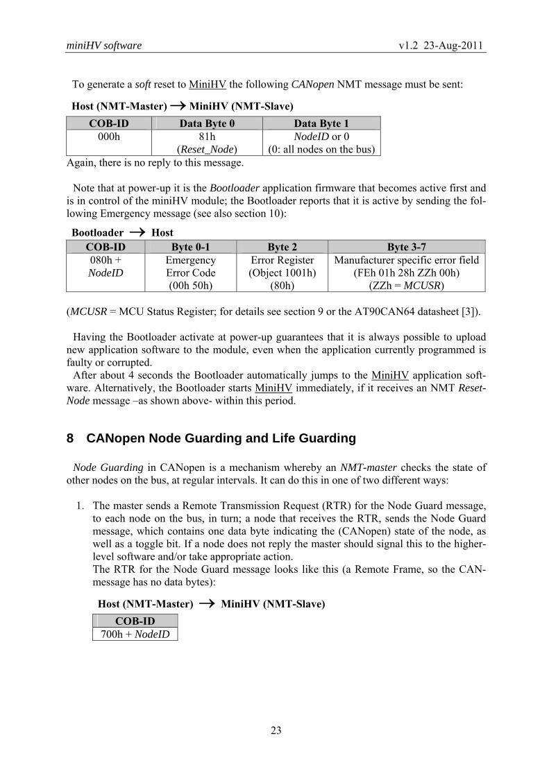
To generate a soft reset to MiniHV the following CANopen NMT message must be sent:
Host (NMT-Master) → MiniHV (NMT-Slave) COB-ID Data Byte 0 Data Byte 1
000h 81h (Reset_Node)
NodeID or 0 (0: all nodes on the bus)
Again, there is no reply to this message. Note that at power-up it is the Bootloader application firmware that becomes active first and
is in control of the miniHV module; the Bootloader reports that it is active by sending the fol-lowing Emergency message (see also section 10):
Bootloader → Host COB-ID Byte 0-1 Byte 2 Byte 3-7 080h + NodeID
Emergency Error Code (00h 50h)
Error Register (Object 1001h)
(80h)
Manufacturer specific error field (FEh 01h 28h ZZh 00h)
(ZZh = MCUSR)
(MCUSR = MCU Status Register; for details see section 9 or the AT90CAN64 datasheet [3]). Having the Bootloader activate at power-up guarantees that it is always possible to upload
new application software to the module, even when the application currently programmed is faulty or corrupted.
After about 4 seconds the Bootloader automatically jumps to the MiniHV application soft-ware. Alternatively, the Bootloader starts MiniHV immediately, if it receives an NMT Reset-Node message –as shown above- within this period.
8 CANopen Node Guarding and Life Guarding
Node Guarding in CANopen is a mechanism whereby an NMT-master checks the state of other nodes on the bus, at regular intervals. It can do this in one of two different ways:
1. The master sends a Remote Transmission Request (RTR) for the Node Guard message,
to each node on the bus, in turn; a node that receives the RTR, sends the Node Guard message, which contains one data byte indicating the (CANopen) state of the node, as well as a toggle bit. If a node does not reply the master should signal this to the higher-level software and/or take appropriate action. The RTR for the Node Guard message looks like this (a Remote Frame, so the CAN-message has no data bytes):
Host (NMT-Master) → MiniHV (NMT-Slave) COB-ID
700h + NodeID

miniHV software v1.2 23-Aug-2011
24
The reply Node Guard message from a node looks like this:
MiniHV (NMT-Slave) → Host (NMT-Master) COB-ID DataByte 0
700h + NodeID bit 7: toggle bit, bit 6-0: state
2. Each node on the bus sends a Heartbeat message at regular intervals; typically, the NMT-master monitors these messages and keeps a time-out period for each node. The master detects nodes that stop sending their Heartbeat messages and should signal this to the higher-level software and/or take appropriate action. A Heartbeat message looks like this:
MiniHV (Heartbeat producer) → Consumer(s) (e.g. NMT-Master) COB-ID DataByte 0
700h + NodeID State State is one of these CANopen states: 0 (Initializing), 4 (Stopped), 5 (Operational) or 127 (Pre-operational). Note that this makes the Boot-up message the first Heartbeat message after a node reset (see previous section).
According to the CANopen standard, a node is not allowed to support both Node Guarding and Heartbeat protocols at the same time. MiniHV supports both methods of Node Guarding (but indeed not at the same time), i.e. it can send the Node Guard message or it can send the Heartbeat message with an interval, which is configurable in OD index 1017h.
Life Guarding in CANopen is a mechanism whereby a node checks the aliveness of the host or master, by applying a time-out on messages received. CANopen defines that the message to time-out is the RTR for the Node Guard message, sent by the NMT-master; however, MiniHV resets its Life Guarding timer at each properly received message addressed to it.
Life Guarding is controlled through OD objects 100Ch and 100Dh. In MiniHV the Life Guarding time-out can be set between 1 and 255 seconds, by setting OD index 100Dh to the corresponding value, or can be switched off, by setting OD index 100Dh to zero.
If a Life Guarding time-out occurs, the node should take whatever action is appropriate. MiniHV resets and reinitializes the CAN-controller, and (tries to) resume(s) normal operation, after sending an Emergency message (see section 10).

miniHV software v1.2 23-Aug-2011
25
9 Object Dictionary
The CANopen Object Dictionary (OD) of MiniHV version 2.3.1 is listed in the tables on the pages below.
The values of objects marked with '∗' in the Index column are stored in the miniHV mod-
ule’s onboard EEPROM for permanent non-volatile storage, on request. They are retrieved from EEPROM at reset and power-up.
Communication Profile Area Index (hex)
Sub Index
Description Data/ Object
Attr Default
Comment
1000 - Device type U32 RO 00000000h Does not comply to any specific
CiA standard device 1001 - Error register U8 RO 0 1002 - Manufacturer status reg U32 RO 0 1
1008 - Manufacturer device name VisStr RO "MiHV" = miniHV module 1009 - Manufacturer hw version VisStr RO "HV20" = miniHV hardware version 2 100A 0 Manufacturer software
version VisStr RO "MH23" MiniHV application version 2.3
1 minor version number VisStr RO "0001" version 2.3.1
100C - Guard time [ms] U16 RO 1000 = 1 second 100D
* - Life time factor U8 RW 0 Life Guarding timeout in seconds;
0 → no life guarding timeout
1 Manufacturer Status Register bits:
Byte 0 = ADC: 01 = ADC reset error, 02 = ADC calibration error, 04 = ADC conversion time-out. Byte 1 = HV: 01 = no voltage calibration constants, 02 = no current calibration constants,
04 = CW board ID read error, 08 = CW board ID mismatch, 10 = 60V supply failure, 20 = HV tripped, 40 = HV driver PWM off.

miniHV software v1.2 23-Aug-2011
26
Communication Profile Area Index (hex)
Sub Index
Description Data/ Object
Attr Default
Comment
1010 Store parameters Array Save stuff in onboard EEPROM
0 Highest index supported U8 RO 5 1 Save all parameters
U32 RW 1 Read: 1; Write "save": store all
(incl. ADC limits) 2 Save communication pa-
rameters U32 RW 1 Read: 1; Write "save": store
PDO par's, Life time factor, … 3 Save application parame-
ters U32 RW 1 Read: 1; Write "save": store
ADC config, dig.I/O config, … (incl. ADC limits)
4 Save ADC delta-change parameters
U32 RW 1 Read: 1; Write "save": store ADC deltas
5 Save ADC upper/lower limit parameters
U32 RW 1 Read: 1; Write "save": store ADC upper/lower liimits
1011 Restore default parameters Array Invalidate stuff in onboard
EEPROM; use defaults 0 Highest index supported U8 RO 5 1 Set all parameters to de-
faults U32 RW 1 Read: 1; Write "load": invalidate
all parameters stored (excl. ADC deltas/limits)
2 Set communication pa-rameters to defaults
U32 RW 1 Read: 1; Write "load": invali-date stored PDO par's, etc.
3 Set application parameters to defaults
U32 RW 1 Read: 1; Write "load": invali-date stored ADC config, etc. (excl. ADC deltas/limits)
4 Set ADC delta-change pa-rameters to defaults
U32 RW 1 Read: 1; Write "load": invalidate ADC deltas
5 Set ADC upper/lower limit parameters to defaults
U32 RW 1 Read: 1; Write "load": invalidate ADC upper/lower limits
1017
* - Producer Heartbeat Time
[1 s] U16 RW 0 In units of seconds (but ≤255 !),
(NB: should be in ms according to CANopen!); 0 → Heartbeat is disabled
1018 Identity Record Mandatory CANopen object
0 Number of entries 1..4 RO 1 1 Vendor ID U32 RO 12345678h to be ordered from CiA

miniHV software v1.2 23-Aug-2011
27
Communication Profile Area (continued…) Index (hex)
Sub Index
Description Data/ Object
Attr Default
Comment
1400 1st Receive PDO parameters Record Data type = PDOCommPar
0 Number of entries U8 RO 5 1 COB-ID used by PDO U32 RO 200h NodeID not included, used to
broadcast to all nodes 2 Transmission type U8 RO 255 Only 255 allowed 3,4,5 Not used RO 0
1401 2nd Receive PDO parameters Record Data type = PDOCommPar 0 Number of entries U8 RO 5 1 COB-ID used by PDO U32 RO 300h +
NodeID According to CANopen Prede-fined Connection Set
2 Transmission type U8 RO 255 3,4,5 Not used RO 0
1600 1st Receive PDO mapping Record Data type = PDOMapping 0 Number of entries U8 RO 1 1 16-bit high-voltage setting U32 RO 20000210 OD index 2000, sub-index 2:
voltage value, size = 16 bits 1601 2nd Receive PDO mapping Record Data type = PDOMapping
0 Number of entries U8 RO 1 1 16-bit high-voltage setting U32 RO 20000210 OD index 2000, sub-index 2:
voltage value, size = 16 bits
1800 1st Transmit PDO parameters Record Data type = PDOCommPar 0 Number of entries U8 RO 5 1 COB-ID used by this PDO U32 RO 180h +
NodeID According to CANopen Prede-fined Connection Set
* 2 Transmission type U8 RW 1 Only 1 allowed 3 Inhibit time [100 μs] U16 RO 0 not used in this application 4 Not used U8 RO 0
* 5 Event timer [1 s] U16 RW 0 In units of seconds (NB: should be in ms according to CANopen!); active if >0 and transmission-type=255
1801 2nd Transmit PDO parameters Record Data type = PDOCommPar 0 Number of entries U8 RO 5 1 COB-ID used by this PDO U32 RO 280h +
NodeID According to CANopen Prede-fined Connection Set
* 2 Transmission type U8 RW 255 Only 1 and 255 allowed 3 Inhibit time [100 μs] U16 RO 0 not used in this application 4 Not used U8 RO 0
* 5 Event timer [1 s] U16 RW 0 In units of seconds (NB: should be in ms according to CANopen!); active if >0 and transm-type=255

miniHV software v1.2 23-Aug-2011
28
Communication Profile Area (continued…) Index (hex)
Sub Index
Description Data/ Object
Attr Default
Comment
1802 3rd Transmit PDO parameters Record Data type = PDOCommPar
0 Number of entries U8 RO 5 1 COB-ID used by this PDO U32 RO 380h +
NodeID According to CANopen Prede-fined Connection Set
* 2 Transmission type U8 RW 255 Only 1 and 255 allowed 3 Inhibit time [100 μs] U16 RO 0 not used
* 5 Event timer [1 s] U16 RW 0 In units of seconds (NB: should be in ms according to CANopen!); active if >0 and transmission-type=255
1A00 1st Transmit PDO mapping Record Data type = PDOMapping
0 Number of entries U8 RO 6 1 U32 RO 20000310h OD index 2000, subindex 3:
HV output voltage 2 U32 RO 20000410h OD index 2000, subindex 4:
HV output current 3 U32 RO 20000510h OD index 2000, subindex 5:
HV output voltage according to bleeder resistor
4 U32 RO 6411010Eh OD index 6411, subindex 1: current DAC value
5 U32 RO 20000501h OD index 2000, subindex 5: bleeder voltage when HV==0
6
U32 RO 25000301h OD index 2500, subindex 3: ramping in progress
1A01 2nd Transmit PDO mapping Record Data type = PDOMapping
0 Number of entries U8 RO 2 should be 255 for a MuxPDO, but this is not a CANopen MPDO…
1 ADC channel number U32 RO 64040008h actually not allowed, but… 2 32-bit analogue input U32 RO 64040x20h OD index 6404, subindex x:
Analogue inputs, multiplexed, size = 32 bits; actually the ADC flag bits (pre-sent in OD index 6404) have been replaced by a byte with ADC config and an error flag (0x80)
1A02 3rd Transmit PDO mapping Record Data type = PDOMapping
0 Number of entries U8 RO 2 should be 255 for a MuxPDO, but this is not a CANopen MPDO…
1 ADC channel number U32 RO 24000008h actually not allowed, but who cares… it’s not important
2 8+32-bit analogue input U32 RO 24000x28h Object 2400, subindex x: Analogue inputs in volts, multiplexed, size = 40 bits: actually the ADC flag bits (pre-sent in Object 2400) have been replaced by a byte combining the ADC configuration and the two ADC error flags; 24-bit data is replaced by a 32-bit signed long

miniHV software v1.2 23-Aug-2011
29
Manufacturer-Specific Profile Area Index (hex)
Sub Index
Description Data/ Object
Attr Default
Comment
2000 High-Voltage parameters Record
0 Number of entries U8 RO 15 1 Set output voltage [V] U16 RW 0 Maximum possible is set in
Object 2000, sub 8 2 Set output voltage [V]
directly U16 RW 0 No ramping done if setting is
lower than current setting (e.g. for fast HV switch-off)
3 Output voltage [0.1V] U16 RO 0 According to: Vout = (a*Vadc/100 + b – c* Iadc* (1+Vadc/v) / 1000 – elog( 1+Iadc/ p ) ) / 100 + 0.35* Iadc* (1– Vadc/27000) 1
or + 7000*(1–Vadc/30000) – 5000*(1– Iadc/23000) 2
4 Output current [pA] I32 RO 0 Iout = e*Iadc + f – Ibleeder 5 Bleeder voltage [0.1V] U16 RO 0 High-voltage output according to
bleeder resistance and current, Ob-jects 2000, sub 6 and 2010, sub 8
6 Bleeder current [pA] U16 RO 0 * 7 Ramp speed [mV/s] U32 RW 0 If != 0 ramp speed is taken into
account; in mV per second, as-suming Vout = (m/100)*DAC + nEquivalent to Object 2500, sub 2
* 8 Maximum allowed output voltage [V]
U16 RW 1020 Maximum high-voltage output allowed (must be ≤ fullscale in OD 2020)
9 HV voltage calibrated Bool RO 0 = 1 if voltage output has been cali-brated
10 HV current calibrated Bool RO 0 = 1 if current output has been calibrated
* 11 Bleeder resistor installed Bool RW 1 12 Temperature sensor
reading [˚mC] I32 RO The ADC input connected to the
onboard temperature sensor is read out and converted to mil-lidegrees centigrade
* 13 T-sensor data in TPDO Bool RW 0 If = 1, DAC value in TPDO1 replaced by temperature
* 14 Voltage according to bleeder in TPDO
Bool RW 0 If = 1, output voltage value in TPDO1 is represented by the bleeder voltage
15 HV supply error status 3 U8 RO 0 Also available in byte 1 of Object 1002 (Manufacturer Status Reg)
1 The last term was added to this formula for a better match between real output voltage and resulting value,
this one used in MiniHV version 2.3.1. 2 Term used in MiniHV version 2.3.2. 3 High-voltage powersupply error status byte bit definitions:
01 = no voltage calibration constants, 02 = no current calibration constants, 04 = CW board ID read error, 08 = CW board ID mismatch, 10 = 60V supply failure, 20 = HV tripped, 40 = HV driver PWM off.

miniHV software v1.2 23-Aug-2011
30
Manufacturer-Specific Profile Area Index (hex)
Sub Index
Description Data/ Object
Attr Default
Comment
2001 High-Voltage control loop
parameters Record
0 Number of entries U8 RO 8 1 Control loop enabled Bool RW 0 = 1 at power-up if module is
calibrated * 2 Control loop interval U8 RW 50 In units of 10 ms, must be > 10 * 3 Output current warning limit U16 RW 0 In nA (0 = not enabled) * 4 Output current trip limit U16 RW 0 In nA (0 = not enabled) * 5 Current trip limit count U8 RW 1 If number of consecutive samples
exceeding the limit reaches this count action is taken (Emergency message indicating high-voltage trip); must be > 0
* 6 Constant p in logarithmic term for current compensa-tion
U8 RW 20 Term is elog( 1+ Iadc / p ) [V]
7 Constant q U8 RW 16 Used to moderate the output volt-age control when controlled using the bleeder voltage (See Object 2001h, sub 8 below)
* 8 Control using bleeder volt-age
Bool RW 0 If = 1, output voltage is controlled using the bleeder voltage calcu-lated from the the bleeder current ADC reading as feedback; this is not recommended

miniHV software v1.2 23-Aug-2011
31
Manufacturer-Specific Profile Area Index (hex)
Sub Index
Description Data/ Object
Attr Default
Comment
2010 High-voltage / ADC
calibration constants Record Vout= (a* Vadc/100 + b
– c*Iadc* (1+Vadc/v) / 1000 – elog( 1+ Iadc / p ) Vout= m*DAC/100 + n – c*Iadc* (1+Vadc/v) / 1000 – elog( 1+ Iadc / p ) Iout = e*Iadc + f (Vadc and Iadc are 16-bit signed ADC readings)
0 Number of entries U8 RO 11 * 1 a I32 RW 3509 In units of 0.01mV, default =
Vfullscale * 100000 / ADCmax = 1150 * 100000 / 32767 (16-bits signed ADC reading)
* 2 b I32 RW 0 In units of mV * 3 c I32 RW 550 In units of μV * 4 e I32 RW 15259 In units of 10fA, default =
Ifullscale * 100000 / ADCmax = 5000 * 100000 / 32767 (16-bits signed ADC reading)
* 5 f I32 RW 0 In units of 10fA * 6 m I32 RW 7019 In units of 0.01mV, default =
Vfullscale * 100000 / DACmax = 1150 * 100000 / 16383 (for a 14-bit DAC)
* 7 n I32 RW 0 In units of mV * 8 r I32 RW 1800 Bleeder resistance value
in units of 0.1GOhm (default = 180 GΩ)
* 9 v I32 RW 60000 10 Erase calibration constants U8 WO Also erases what’s stored in
Object 2011 (EXPERT ONLY) 11 Store calibration constants U8 WO Store current calibration con-
stants’ values (EXPERT ONLY)
2011 CW-board ID associated with calibration constants
Record Compare with Object 2030 (= ID of current CW-board)
0 Number of entries U8 RO 2 * 1 CW-board ID bytes 0-3 U32 RO 0 * 2 CW-board ID bytes 4-7 U32 RO 0

miniHV software v1.2 23-Aug-2011
32
Manufacturer-Specific Profile Area Index (hex)
Sub Index
Description Data/ Object
Attr Default
Comment
2012 High-voltage / ADC
calibration sequence: ex-ternal voltage readings
Record Vn = m*DAC/100 + n – c* Iadc* (1+Vadc/v) / 1000 – elog( 1+ Iadc / p ) or Vn = a*Vadc/100 + b – c* Iadc* (1+Vadc/v) / 1000 – elog( 1+ Iadc / p ) (Vn is a reading from an external voltmeter, Vadc, Iadc are ADC readings, DAC is the DAC set-ting)
0 Number of entries U8 RO 4 1 V1 U16 WO Ext measured V1, in V, assuming
Iadc = 0 2 V2 U16 WO Ext measured V2, in V, assuming
Iadc = 0 a, b, m, n and r are calculated and stored
3 V3 (not used anymore see section 11)
U16 WO Ext measured V3, in V with I adc > 0
4 V4 (not used anymore see section 11)
U16 WO Ext measured V4, in V with I adc >> 0, c is calculated and stored
2013 High-voltage / ADC
calibration sequence: ex-ternal current readings
Record In = e* Iadc + f – Ibleeder (In is a reading from an external ampmeter, Iadc an ADC reading, Ibleeder is the bleeder current)
0 Number of entries U8 RO 2 1 I1 U16 WO Externally measured I1, in 0.1nA 2 I2 U16 WO Externally measured I2, in 0.1nA,
e and f are calculated and stored
2020 *
- High-voltage output voltage full-scale [V]
U16 RW 1150 High-voltage supply fullscale output voltage measured by fullscale ADC reading, in V
2021
* - High-voltage output current
full-scale [nA] U16 RW 5000 High-voltage supply fullscale
output current measured by fullscale ADC reading, in nA
2030 Cockcroft-Walton high-
voltage board identification Record DS2431 identification chip con-
taining a unique 8-byte serial number
0 Number of entries U8 RO 2 1 First 4 bytes U32 RO 2 Second 4 bytes U32 RO
miniHV software v1.2 23-Aug-2011
33
Manufacturer-Specific Profile Area Index (hex)
Sub Index
Description Data/ Object
Attr Default
Comment
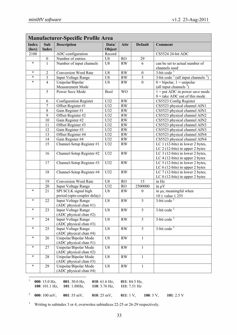
2100 ADC-configuration Record CS5524 24-bit ADC 0 Number of entries U8 RO 29
* 1 Number of input channels U8 RW 6 can be set to actual number of channels used
* 2 Conversion Word Rate U8 RW 0 3-bit code 1 * 3 Input Voltage Range U8 RW 5 3-bit code 2 (all input channels 3) * 4 Unipolar/Bipolar
Measurement Mode U8 RW 0 0 = bipolar, 1 = unipolar
(all input channels 3) 5 Power Save Mode Bool WO 1 = put ADC in power save mode
0 = take ADC out of this mode 6 Configuration Register U32 RW CS5523 Config Register 7 Offset Register #1 U32 RW CS5523 physical channel AIN1 8 Gain Register #1 U32 RW CS5523 physical channel AIN1 9 Offset Register #2 U32 RW CS5523 physical channel AIN2 10 Gain Register #2 U32 RW CS5523 physical channel AIN2 11 Offset Register #3 U32 RW CS5523 physical channel AIN3 12 Gain Register #3 U32 RW CS5523 physical channel AIN3 13 Offset Register #4 U32 RW CS5523 physical channel AIN4 14 Gain Register #4 U32 RW CS5523 physical channel AIN4 15 Channel-Setup Register #1 U32 RW LC 1 (12-bits) in lower 2 bytes,
LC 2 (12-bits) in upper 2 bytes 16 Channel-Setup Register #2 U32 RW LC 3 (12-bits) in lower 2 bytes,
LC 4 (12-bits) in upper 2 bytes 17 Channel-Setup Register #3 U32 RW LC 5 (12-bits) in lower 2 bytes,
LC 6 (12-bits) in upper 2 bytes 18 Channel-Setup Register #4 U32 RW LC 7 (12-bits) in lower 2 bytes,
LC 8 (12-bits) in upper 2 bytes 19 Conversion Word Rate U8 RO 15 in Hz 20 Input Voltage Range U32 RO 2500000 in μV
* 21 SPI SCLK signal high period (opto-coupler delay)
U8 RW 0 in μs, meaningful when 10 ≤ value ≤ 255
* 22 Input Voltage Range (ADC physical chan #1)
U8 RW 5 3-bit code 2
* 23 Input Voltage Range (ADC physical chan #2)
U8 RW 5 3-bit code 2
* 24 Input Voltage Range (ADC physical chan #3)
U8 RW 5 3-bit code 2
* 25 Input Voltage Range (ADC physical chan #4)
U8 RW 5 3-bit code 2
* 26 Unipolar/Bipolar Mode (ADC physical chan #1)
U8 RW 1
* 27 Unipolar/Bipolar Mode (ADC physical chan #2)
U8 RW 1
* 28 Unipolar/Bipolar Mode (ADC physical chan #3)
U8 RW 1
* 29 Unipolar/Bipolar Mode (ADC physical chan #4)
U8 RW 1
1 000: 15.0 Hz, 001: 30.0 Hz, 010: 61.6 Hz, 011: 84.5 Hz,
100: 101.1 Hz, 101: 1.88Hz, 110: 3.76 Hz, 111: 7.51 Hz
2 000: 100 mV, 001: 55 mV, 010: 25 mV, 011: 1 V, 100: 5 V, 101: 2.5 V 3 Writing to subindex 3 or 4, overwrites subindices 22-25 or 26-29 respectively.

miniHV software v1.2 23-Aug-2011
34
Manufacturer-Specific Profile Area Index (hex)
Sub Index
Description Data/ Object
Attr Default
Comment
2400 Read Analogue Input Voltage
Record Read out as: 8 bits flags 1, 24 bits analogue value, in μV; represents same inputs as in Object 6404
0 Number of analog inputs U8 RO 6 Fixed, but actual hardware con-figuration may vary (set in Object 2100, sub 1)
1 High-voltage output voltage U32 RO 1st analog input: 8-bit flags 1 + 24-bit (signed) data
2 High-voltage output current U32 RO … 3 Bleeder current U32 RO … 4 Temperature sensor U32 RO See also Object 2000, sub 12 5 Driver output U32 RO 5th analog input:
10-bit data in 2nd and 3rd byte 6 Driver supply U32 RO …
2500 DAC configuration Record 0 Number of entries U8 RO 6
* 1 SPI SCLK signal high period (opto-coupler delay)
U8 RW 0 in μs, meaningful when 10 ≤ value ≤ 255
* 2 Ramp speed U16 RW 0 If != 0 ramp speed is taken into account; in DAC-counts per sec (also see Object 2000, sub 5)
3 Ramping pause/continue Bool RW 0 Ramping in progress or not (read),pause/continue ramping (write)
* 4 Percentage of DAC end value at which to switch from linear to exponential ramping
U8 RW 100 The percentage of the requested DAC end-value at which up-ramping (not down) switches from linear to exponential, taking the set ramp speed into account
* 5 Minimum ramp speed dur-ing exponential ramp
U16 RW 10 > 0; during exponential ramp the speed will not fall below this value, i.e. becomes linear again; in DAC-counts per sec
6 DAC setting U16 RO Currently requested final value for DAC (ramp may be in pro-gress); current DAC value to be read from Object 6411, sub 1 or 2
2600 PWM configuration Record Configuration of PWM wave-
forms on AT90CAN64 output pins OC3B/C, used for HV gen
0 Number of entries U8 RO 4 * 1 Start at power-up Bool RW 1 Start at power-up or not * 2 Frequency U8 RW 3 1 = 25KHz, 2 = 50KHz,
3 = 100KHz, 4 = 200KHz NB: if changed, calibration invalid
* 3 Gap size U8 RW 1 Gap between waveforms positive pulses, in units of system clock period (4 MHz, i.e. 250 ns)
4 PWM stop/start Bool RW 1 Read: PWM is running or not; write: start or stop the PWM
1 See section 5.1.2 for a description of the ADC 'flags' byte.

miniHV software v1.2 23-Aug-2011
35
Manufacturer-Specific Profile Area (continued…) Index (hex)
Sub Index
Description Data/ Object
Attr Default
Comment
3000 Program Code CRC Record 0 Number of entries U8 RO 3 1 Check 16-bit CRC of pro-
gram code in FLASH memory
U16 RO 0 SDO reply unequal to zero means there is a checksum error; absence of CRC in flash results in SDO Abort with Error Code 1; error while accessing FLASH re-sults in SDO Abort with Error Code 6
2 not used U16 RO 0 3 Get CRC U16 RO Return CRC from flash
3100 - Serial Number U32 RW Number or 4-byte string uniquely identifying a module, given during production
3101 - Enable Serial Number write operation
U8 WO DON’T USE
Writing 5Ah enables one write operation on the Serial Number (Object 3100).
3200 CAN-controller settings
and status Record
0 Number of entries U8 RO 4 1 Format error interrupt
counters U32 RO Byte 0: SERG
Byte 1: CERG Byte 2: FERG Byte 3: AERG
* 2 Enable auto-start U8 RW 1 If =1 go to Operational at startup * 3 Bus-off max retry counter U8 RW 2 Counter is decremented every 1s,
but if the node reaches this maximum value it abandons re-gaining CAN-bus access for good
4 Received message counter U8 RO Counts received CAN messages modulo 256 (for debug purposes)
3300 - CAN Node Identifier U8 WO The new CAN Node Identifier is
used after the next reset 3301 - Enable CAN Node Identi-
fier write operation U32 WO Writing a number that matches
the Serial Number (as in Object 3100) enables one write opera-tion on the CAN Node Identifier(Object 3300)

miniHV software v1.2 23-Aug-2011
36
Manufacturer-Specific Profile Area (continued…) Index (hex)
Sub Index
Description Data/ Object
Attr Default
Comment
5C00 - Compile Options U32 RO Bitmask denoting which compile
options were used when the ap-plication was generated (see table below for details)
5E00 - Transfer control to Boot-
loader application U8 WO MiniHV jumps to the Bootloader
application Object 5C00: Compile Options Bit Option Comment
0 VARS_IN_EEPROM Store/retrieve working copies of configuration parameters in/from EEPROM (for improved radiation-tolerance of the running software)
1-4 – – 5 AT90CAN32 Code compiled for AT90CAN32 microcontroller 6 AT90CAN64 Code compiled for AT90CAN64 microcontroller 7 AT90CAN128 Code compiled for AT90CAN128 microcontroller
Standardized Device Profile Area (according to CiA-DS4O1) Index (hex)
Sub Index
Description Data/ Object
Attr Default
Comment
6404 Read Analogue Input
manufacturer-specific Record Read out as:
8 bits flags 1, 24 bits ADC count;see also Object 2400
0 Number of analog inputs U8 RO 6 Fixed, but actual hardware con-figuration may vary (see OD index 2100, sub 1)
1 High-voltage output voltage U32 RO 1st analog input:8-bit flags 1 + 24-bit (signed) ADC data
2 High-voltage output current U32 RO … 3 Bleeder current U32 RO … 4 Temperature sensor U32 RO See also Object 2000, sub 12 5 Driver output U32 RO 5th analog input:
+ 10-bit data in 2nd and 3rd byte 6 Driver supply U32 RO …
6411 Write Analogue Out 16-bit Array miniHV DAC device
0 Number of 16-bit outputs U8 RO 2 1 Output 1 U16 RW 1st analog output:16-bit 2 Output 2 U16 RW 2nd analog output:16-bit
(NB: here the same as 1st input, except that in this case high-voltage ramp down is not done: output is set directly to its value)
1 See section 5.1.2 for a description of the ADC 'flags' byte.

miniHV software v1.2 23-Aug-2011
37
10 Emergency Objects
Emergency messages are triggered by the occurrence of an internal (fatal) error situation. An emergency CAN-message has the following general syntax:
MiniHV → Host COB-ID Byte 0-1 Byte 2 Byte 3-7 080h + NodeID
Emergency Error Code
Error Register (Object 1001h)
Manufacturer specific error field
The most significant bit of byte 7 of the Emergency message is a toggle bit. So byte 7 alter-
nates between value 00h and 80h from one Emergency message to the next. The following Emergency messages listed in may be generated by the MiniHV application
(note that byte 2 containing the Error Register is not included in the table; see Table 4 below for that).
Table 3. List of possible Emergency messages from the MiniHV application.
Error Description
Emergency Error Code
(byte 1-0)
Manufacturer-Specific Error Field (byte 3-7)
CAN communication 8100h Byte 3: 00h
Byte 4: total format error count Byte 5: error counter Byte 6: bus-off counter (see OD index 3200, sub 3)
CAN buffer overrun 8110h CAN message buffer in RAM full: at least 1 message was lost Life Guarding time-out 8130h CAN-controller has been reinitialized RPDO: too few bytes 8210h Byte 3: minimum DLC (Data Length Code) required ADC: conversion timeout
5000h Byte 3: 01h Byte 4: ADC channel number (0..63) Byte 5: 0
ADC: reset failed
5000h Byte 3: 02h Byte 4: 00h Byte 5: Error id 1
ADC: calibration failed 5000h Byte 3: 03h Byte 4: 00h (offset calibration) or 01h (gain calibration)
ADC problem(s) during initialisation
5000h Byte 3: 04h Byte 4: ADC status byte (see OD index 1002)
DAC problem(s) during initialisation
5000h Byte 3: 11h Byte 4: 0
DAC: illegal setting 5000h Byte 3: 12h Byte 4+5: DAC setting
…table continues on the next page…
1 01h: Reset-Valid bit not set, 02h: Reset-Valid bit not reset, 04h: error in initial Offset Register value,
08h: error in initial Gain Register value.

miniHV software v1.2 23-Aug-2011
38
Error
Description Emergency Error Code
(byte 1-0)
Manufacturer-Specific Error Field (byte 3-7)
HV problem(s) during initialisation
5000h Byte 3: 21h Byte 4: HV status byte (see OD index 1002)
HV: illegal setting 5000h Byte 3: 22h Byte 4+5: HV voltage setting
HV driver supply absent 5000h Byte 3: 23h HV current warning limit exceeded
5000h Byte 3: 24h
HV current trip limit exceeded
5000h Byte 3: 25h
HV driver PWM off 5000h Byte 3: 26h CRC error 5000h Byte 3: 30h
Byte 4: 1 (program code in Flash memory) EEPROM: write error 5000h Byte 3: 41h
Byte 4: Parameter block index 1 Byte 5: = 0: while writing datablock info > 0: size of parameter block to write
EEPROM: read error 5000h Byte 3: 42h Byte 4: Parameter block index 1
Byte 5: Error id (1=CRC, 2=length, 4=infoblock) Irregular reset (Watchdog, Brown-out or JTAG)
5000h Byte 3: F0h Byte 4: microcontroller MCUSR register contents 2
Bootloader: not present 5000h Byte 3: F1h Bootloader is now in control 3
5000h Byte 3: FEh Byte 4: 81h (80h in case of an AT90CAN64/32 micro) Byte 5: 28h (64h for AT90CAN64, 32h for AT90CAN32) Byte 6: microcontroller MCUSR register contents 2
Bootloader cannot jump to application: invalid 3
6000h Byte 3: FEh Byte 4: AAh Byte 5: AAh
1 0: PDO communication parameters, 1: Guarding parameters, 2: ADC configuration, 3: DAC configuration,
4: CAN configuration parameters, 5: PWM configuration parameters, 6: HV configuration parameters, 7: HV calibration constants, FFh: Serial Number.
2 AT90CANxx MCUSR register bits: 01h: Power-On Reset, 02h: External Reset, 04h: Brown-Out Reset, 08h: Watchdog Reset, 10h: JTAG Reset.
3 The Emergency message is generated by the Bootloader program !

miniHV software v1.2 23-Aug-2011
39
Byte 2 of the Emergency message contains the value of the so-called Error Register (Object
Dictionary index 1001h, a mandatory CANopen object). One or more bits of the 8-bit Error Register may be set to 1, depending on the node's history of errors since the last reset. Table 4 below gives a description of the meaning of the various bits.
Table 4. Definition of CANopen Error Register bits.
Error Register (Object 1001h) bits Bit Error type 0 generic 1 current 2 voltage 3 temperature 4 communication 5 device profile specific 6 reserved (=0) 7 manufacturer specific
11 Calibration Procedure The calibration of the miniHV module is done at production and there should be no need for
the user to redo it at any time. The description of the calibration given here is for documenta-tion purposes only. Calibration is required to enable MiniHV to provide the user with actual voltages and cur-
rents in physical units, i.e. in Volt and Ampere respectively and to allow it to accurately set and regulate the output voltage and check the set current limits. When the output voltage of miniHV is set to a certain voltage and the output current load
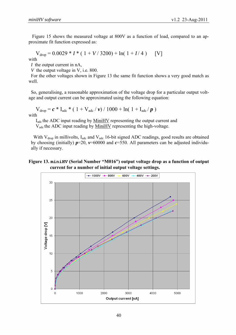
increases then the voltage –if not regulated– decreases. Figure 13 shows the voltage drop measured by an independent external voltmeter at a num-
ber of initial MiniHV output voltages as a function of the current load (the readings in the fig-ure are taken with miniHV module serial number “M016”). The current load readings were taken from the miniHV module itself, which was calibrated for current beforehand. Note that here the PWM driver (driving the Cockcroft-Walton voltage multiplier) is set to 100 KHz; changing this frequency would change the voltage drop slope considerably (a lower PWM fre-quency causes a larger voltage drop). The plots show that apart from a non-linear drop at low current load the voltage drop in-
creases linearly as a function of the current load and also that this linear factor increases for higher output voltages, as shown in Figure 14. The increase of this factor can be approximated by a linear dependency on the voltage. Therefor the voltage drop as a function of output cur-rent can be approximated by a term which is linearly dependent on the current plus a term which is linearly dependent on current and voltage plus a log-term to account for the non-linear voltage-drop at low currents.
miniHV software v1.2 23-Aug-2011
40
Figure 15 shows the measured voltage at 800V as a function of load, compared to an ap-
proximate fit function expressed as:
Vdrop = 0.0029 * I * ( 1 + V / 3200) + ln( 1 + I / 4 ) [V] with I the output current in nA, V the output voltage in V, i.e. 800. For the other voltages shown in Figure 13 the same fit function shows a very good match as
well. So, generalising, a reasonable approximation of the voltage drop for a particular output volt-
age and output current can be approximated using the following equation:
Vdrop = c * Iadc * ( 1 + Vadc / v) / 1000 + ln( 1 + Iadc / p ) with
Iadc the ADC input reading by MiniHV representing the output current and Vadc the ADC input reading by MiniHV representing the high-voltage.
With Vdrop in millivolts, Iadc and Vadc 16-bit signed ADC readings, good results are obtained by choosing (initially) p=20, v=60000 and c=550. All parameters can be adjusted individu-ally if necessary.
Figure 13. miniHV (Serial Number “M016”) output voltage drop as a function of output current for a number of initial output voltage settings.

miniHV software v1.2 23-Aug-2011
41
Figure 14. Plot of output voltage drop per unit of current load as a function of output voltage (numbers derived from Figure 13, i.e. the slopes of the plots).
Figure 15. Plot showing output voltage drop as a function of output current I at 800V output as well as a fit according to Vdrop = .0029*I*(1+800/3200) + elog(1+I/4).

miniHV software v1.2 23-Aug-2011
42
Here is a description of the sequence of steps and actions currently done to calibrate a miniHV module (ADC readings used in the calibration sequence are 16-bit signed values):
1. Make sure the control loop is disabled and not active (the control loop is enabled if the module has been calibrated before, and this is a recalibration).
2. Voltage calibration: set the DAC to setting D1 (e.g. 2000, ca. 130V), no output load (except bleeder) by applying a compensating high-voltage, measure output voltage V1 and write value to MiniHV (Object 2012h, sub 1).
3. Set the DAC to settting D2 (e.g. 12000, ca.850V), no output load (except bleeder) by applying a compensating high-voltage, measure output voltage V2 and write value to MiniHV (Object 2012h, sub 2): • MiniHV calculates constants m and n (to convert DAC setting to actual output
voltage) from: V1 = m*D1 + n V2 = m*D2 + n
• (Using m and n MiniHV determines the resulting fullscale voltage setting Vfull: Vfull = m*Dmax + n = m*0x3FFF + n = 16383*m +n )
• MiniHV calculates constants a and b (to convert from output voltage ADC read-ing to actual output voltage in V) from the voltage ADC readings V1adc and V2adc: V1 = a*V1adc + b V2 = a*V2adc + b
• MiniHV calculates bleeder resistance value r from the bleeder current ADC (range 2.5V) reading IbleederADC across an internal 100 MΩ resistor: r = (V2 / (IbleederADC * 2.5 / 0x7FFF)) * 100*106
4. Now connect a load of 200 MΩ and enable the MiniHV control loop (Object 2001h, sub 1).
5. Set the voltage to 1000V (Object 2000h, sub 1) and measure the output voltage (external meter); adjust constant c (Object 2010h, sub 3) until the meter also reads 1000V (increase constant c to increase the externally measured voltage). NB: at 1000V and a 200 MΩ load, the output current is around its maximum of 5000 nA.
6. Read the value of constant a (Object 2010h, sub 1) and adjust it until the MiniHV also provides 1000V as the output voltage (Object 2000, sub 3).
7. Current calibration: go back to an output load of 1 GΩ, set the DAC to setting D3 (e.g. 2000), measure output current I1 and write value to MiniHV (Object 2013h, sub 1). (Alternatively leave the DAC setting to a high value, but apply a compensation high-voltage to arrive at a low current load I1.)
8. Leaving the load connected to the output, set the DAC to setting D4 (e.g. 14000), meas-ure output current I2, making sure I2 is (much) larger than I1, and write value to MiniHV (Object 2013h, sub 2): • MiniHV calculates constants e and f (to convert from output current ADC reading to
output current in Ampere) from: I1 = e*I1adc + f – I1bleeder I2 = e*I2adc + f – I2bleeder (Note the bleeder current corrections I1bleeder and I2bleeder: the externally measured currents I1 and I2 do not include the bleeder current, so is subtracted.)
• (Using e and f MiniHV determines a fullscale current reading Ifull (no bleeder cur-rent): Ifull = e*0x7FFF + f = 32767*e + f )

miniHV software v1.2 23-Aug-2011
43
Figure 16 (left plot) shows how the miniHV output voltage depends on the setting of the DAC, with no load connected to the miniHV module except the bleeder resistance. This is a linear dependency and can be described, as done in the description above, by Vout = m*D + n, with m and n constants and D the DAC setting (a 14-bit value).
Figure 16 (right plot) shows how the miniHV ADC reading from a parallel Cockcroft-Walton stage representing the output voltage depends on the setting of the DAC, with no load con-nected to the miniHV module except the bleeder resistance. Again, this is a linear dependency, so that the actual output voltage also depends linearly on this ADC reading, and can be de-scribed, as done in the description above, by Vout = a*Vadc + n, with a and b constants and Vadc the ADC reading.
Figure 16. Left plot: externally measured miniHV output voltage as a function of DAC setting (no load, except bleeder). Right plot: miniHV ADC reading representing the output voltage as a func-tion of DAC setting (no load, except bleeder)
Figure 17. Plot showing dependency of the ADC reading representing the output volt-age on the miniHV current load.

miniHV software v1.2 23-Aug-2011
44
Although it is not taken into account in the calibration described above, the ADC reading representing the (uncompensated) output voltage Vadc also has a dependency on the current load of the miniHV module. This is shown in Figure 17 above: the value decreases when the load increases. An extra term was added to the conversion formula of Vadc to actual output voltage to take this into account (see Object 2000, sub 3 in the OD tables). Figure 18 shows another ‘feature’ of the miniHV module: if the bleeder resistance would be constant a linear dependency would be expected for the bleeder current ADC reading (the voltage across a 100 MΩ resistor in series with the nominal bleeder resistor chain of approxi-mately 180 GΩ) and the high-voltage output if the bleeder resistance is constant. This is clearly not the case as shown by the straight line (dashed) in the same figure. Changing the miniHV load does not influence this behaviour. So when MiniHV returns the output voltage according to the bleeder current, this characteris-
tic is taken into account when converting the bleeder current reading to an output voltage: a compensating term dependent on the square of the bleeder current reading is added and results in a good approximation of the output voltage:
Vout = r * Ibl * 25 / 0x7FFF – (Ibl * Ibl) / 100000 [.1V] with
Ibl the 16-bit signed ADC input reading by MiniHV representing the bleeder current and r the nominal bleeder resistance value (in units of 0.1GΩ) as determined in the calibration procedure described above.
Figure 18. Plot showing the bleeder current ADC reading by MiniHV as a function of the miniHV output voltage, compared to a linear dependency (dashed line). Measurements made with miniHV “M016” connected to a 200 MΩ load.

miniHV software v1.2 23-Aug-2011
45
12 EEPROM Memory Map
Table 5 below details the usage of the EEPROM of the AT90CAN64 microcontroller by the MiniHV software.
Table 5. AT90CAN64 microcontroller EEPROM memory map of the MiniHV software.
EEPROM ADDR not used 0000h 0001h MiniHV
configuration
parameters 00A0h 00A1h
Rad-tolerant
working copy
of global
settings and parameters 00FEh not used 00FFh MiniHV 0100h
Serial
Number 0106h
Node-ID (opt) 0107h
0108h 01FFh Voltage 0200h
calibration
constants 021Fh
Current 0220h
calibration
constants 022Fh
Cockcroft- 0240h
Walton board
identifier 0247h
0248h not used 0FFFh
Holds a copy of most application configura-tion and settings and some other parameters that normally don't change very often; pa-rameters are reread from EEPROM each time before being used; this is an optional (compi-lation) feature of the software to counter ef-fects of SEE (Single Event Upset). The code will have a slightly larger size and run slower with this feature enabled.
Holds permanently saved application configu-ration and settings, stored in up to 8 blocks of up to 16 bytes each; includes a CRC checksum for each data block.
DESCRIPTION
Holds the module’s Serial Number given to it at production time; serves to uniquely identify the module.
The 'Node-ID' location contains the CAN Node-ID for the module as used in the CANopen Predefined Connection Set; if the location does not contain a valid number (1<=val<=127) a default of 31 is used.
Constants a, b, c, m, n, r and v (see text).
Constants e and f (see text).
64-bit identifier of the Cockroft-Walton plug-on board associated with the stored voltage and current calibration constants..

miniHV software v1.2 23-Aug-2011
46
Table 6. Detailed EEPROM memory map of the miniHV module’s Serial Number stor-age space. Example: serial number “M123”, is stored with ‘M’ (4Dh) in ad-dress 100h, ‘1’ (31h) in 101h, ‘2’ (32h) in 102h and ‘3’ (33h) in 103h.
EEPROM ADDR
char 0 (ASCII) 0100 char 1 (ASCII) 0101 char 2 (ASCII) 0102 char 3 (ASCII) 0103
CRC MSB 0104 CRC LSB 0105
‘V’ (56h) 0106
References [1] H.L.Groenstege, J.J.Kuijt,
miniHV V2, a modular, remote-controlled high-voltage system, internal document, NIKHEF, Amsterdam, Jan 2011.
[2] H.Boterenbrood,
CANopen, high-level protocol for CAN-bus, Version 3.0, NIKHEF, Amsterdam, 20 March 2000, http://www.nikhef.nl/pub/departments/ct/po/doc/CANopen30.pdf
[3] 8-bit AVR Microcontroller with 32K/64K128K Bytes of ISP Flash and CAN
Controller, AT90CAN32, AT90CAN64, AT90CAN128, ATMEL product datasheet. http://www.atmel.com/products/avr/
[4] CRYSTAL CS5521/22/23/24/28, 16-Bit or 24-bit, 2/4/8-Channel ADCs with
PGIA, CIRRUS LOGIC product datasheet, DS317F8, July 2009, http://www.cirrus.com