
Software Engineering · SOFTWARE PROCESS AND PROJECT MANAGEMENT: Introduction to software...
616
INSTITUTE OF AERONAUTICAL ENGINEERING (Autonomous) Dundigal, Hyderabad – 500 043 Software Engineering Course Code: ACS008 IV Semester (IARE – R16) Prepared by: Ms. B.DHANA LAXMI Assistant Professor Mr. A. PRAVEEN Assistant Professor 1
Transcript of Software Engineering · SOFTWARE PROCESS AND PROJECT MANAGEMENT: Introduction to software...
INSTITUTE OF AERONAUTICAL ENGINEERING(Autonomous)
Dundigal, Hyderabad – 500 043
Software EngineeringCourse Code: ACS008
IV Semester (IARE – R16)
Prepared by:
Ms. B.DHANA LAXMI
Assistant Professor
Mr. A. PRAVEEN
Assistant Professor
1
SOFTWARE PROCESS AND PROJECT MANAGEMENT:
Introduction to software engineering, software process, perspective
and specialized process models; Software project management:
Estimation: LOC and FP based estimation, COCOMO model;
Project scheduling: Scheduling, earned value analysis, risk
management
1. Roger S. Pressman, “Software Engineering – A Practitioner‟s
Approach”, McGraw-Hill International Edition, 7th Edition,
2010.
2. Ian Somerville, “Software Engineering”, Pearson Education
Asia, 9th Edition, 2011.
UNIT-I
2
What is Software
3
The product that software professionals build and then support
over the long term.
Software encompasses:
(1) instructions (computer programs) that when executed provide
desired features, function, and performance;
(2) data structures that enable the programs to adequately store and
manipulate information and
(3) documentation that describes the operation and use of the
programs.
Software products
4
Generic products
Stand-alone systems that are marketed and sold to any customer
who wishes to buy them.
Examples – PC software such as editing, graphics programs,
project management tools; CAD software; software for specific
markets such as appointments systems for dentists.
Customized products
Software that is commissioned by a specific customer to meet
their own needs.
Examples – embedded control systems, air traffic control
software, traffic monitoring systems.
3
Why Software is Important?
5
The economies of ALL developed nations are dependent on
software.
More and more systems are software controlled ( transportation,
medical, telecommunications, military, industrial, entertainment,
etc…)
Software engineering is concerned with theories, methods and tools
for professional software development.
Expenditure on software represents asignificant fraction of Gross national product (GNP) in all developed countries.
Features of Software?
6
Its characteristics that make it different from other things humanbeing build.
Features of such logical system:
Software is developed or engineered, it is not manufactured in theclassical sense which has quality problem.
Software doesn't "wear out.” but it deteriorates (due to change).
Hardware has bathtub curve of failure rate ( high failure rate in the
beginning, then drop to steady state, then cumulative effects of dust, vibration, abuseoccurs).
Although the industry is moving toward component-basedconstruction (e.g. standard screws and off-the-shelf integratedcircuits), most software continues to be custom-built. Modernreusable components encapsulate data and processing into softwareparts to be reused by different programs. E.g. graphical userinterface, window, pull-down menus in library etc.
7
Software Myths
• Software Myths
– Software myths – beliefs about software and the process used to
build it
– Management Myths
• Myth – We already have a book that’s full of standards and
procedures for building software. Won’t that provide my people
with everything they need to know?
• Reality – The book of standards may very well exist but is it
used? Are software practitioners aware of its existence? Does it
reflect modern software engineering practice? Is it adaptable?
• Myth – If we get behind schedule, we can add more
programmers and catch up
• Reality – Software development is not a mechanistic process
like manufacturing. ― Adding more people to a late software
project makes it later‖
8
Software Myths• Software Myths
– Software myths – beliefs about software and the process used to
build it
– Management Myths
• Myth – If I decide to outsource the software project to a third
party, I can relax and let that firm build it
• Reality – If an organization does not understand how to
manage and control software projects internally, it will
invariably struggle when it is outsourced.
9
Software Myths
• Software Myths
– Customer Myths
• Myth – A general statement of objectives is sufficient to begin
writing programs – we can fill in the details later
• Reality – An ambiguous statement of objectives is a recipe for
disaster. Unambiguous requirements are developed only
through effective and continuous communication between
customer and developer
• Myth – Project requirements change, but change can be easily
accommodated because software is flexible
• Reality – When requirement changes are requested early, cost
impact is relatively small. With time, cost impact grows
rapidly, and a change can cause additional resources and major
design modifications
10
Software Myths
• Software Myths
– Practitioner Myths
• Myth – Once we write the program and get it to work, our job
is done
• Reality – The sooner you begin writing code, the longer it will
take you to get done. Between 60 to 80 percent of all effort
spent on software will be spent after it is delivered to the
customer for the first time
• Myth – Until I get the program running, I have no way of
assessing its quality
• Reality – Software reviews are a ―quality filter‖ that have been
found to be more effective than testing for finding certain
classes of software errors
11
Software Myths
• Software Myths
– Practitioner Myths
• Myth – The only deliverable work product for a successful
project is the working program
• Reality – A working program is only one part of a software
configuration that includes many elements. Documentation
provides a foundation for successful engineering and guidance
for software support
• Myth – Software engineering will make us create voluminous
and unnecessary documentation and will invariably slow us
down
• Reality – Software engineering is not about creating
documents, it si about creating quality. Better quality leads to
reduced rework. Reduced rework results in faster delivery
times
Software Applications
12
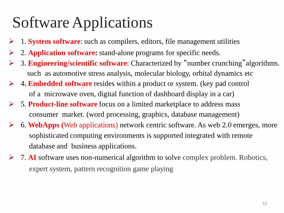
1. System software: such as compilers, editors, file management utilities
2. Application software: stand-alone programs for specific needs.
3. Engineering/scientific software: Characterized by “number crunching”algorithms.
such as automotive stress analysis, molecular biology, orbital dynamics etc
4. Embedded software resides within a product or system. (key pad control
of a microwave oven, digital function of dashboard display in a car)
5. Product-line software focus on a limited marketplace to address mass
consumer market. (word processing, graphics, database management)
6. WebApps (Web applications) network centric software. As web 2.0 emerges, more
sophisticated computing environments is supported integrated with remote
database and business applications.
7. AI software uses non-numerical algorithm to solve complex problem. Robotics,
expert system, pattern recognition game playing
The seminal definition:
[Software engineering is] the establishment and use of sound
engineering principles in order to obtain economically
software that is reliable and works efficiently on real
machines.
The IEEE definition:
Software Engineering: (1) The application of a systematic,
disciplined, quantifiable approach to the development,
operation, and maintenance of software; that is, the
application of engineering to software. (2) The study of
approaches as in (1).
Software Engineering Definition
13
Importance of Software Engineering
14
More and more, individuals and society rely on advanced
software systems. We need to be able to produce reliable and
trustworthy systems economically and quickly.
It is usually cheaper, in the long run, to use software
engineering methods and techniques for software systems
rather than just write the programs as if it was a personal
programming project. For most types of system, the majority of
costs are the costs of changing the software after it has gone
into use.
FAQ about software engineering
15
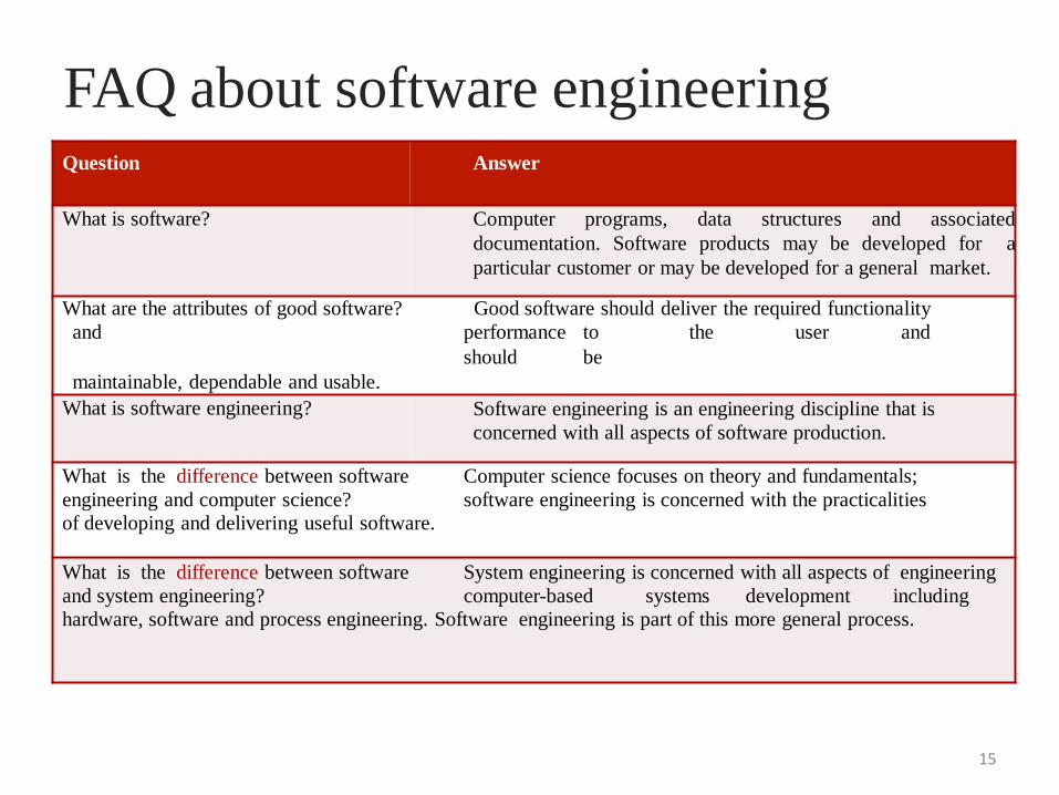
Question Answer
What is software? Computer programs, data structures and associated
documentation. Software products may be developed for a
particular customer or may be developed for a general market.
What are the attributes of good software? Good software should deliver the required functionality
and performance to the user and
should be
maintainable, dependable and usable.
What is software engineering? Software engineering is an engineering discipline that is
concerned with all aspects of software production.
What is the difference between software Computer science focuses on theory and fundamentals;
engineering and computer science? software engineering is concerned with the practicalities
of developing and delivering useful software.
What is the difference between software System engineering is concerned with all aspects of engineering
and system engineering? computer-based systems development including
hardware, software and process engineering. Software engineering is part of this more general process.
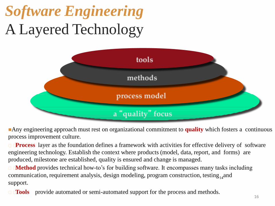
Software Engineering
A Layered Technology
16
Any engineering approach must rest on organizational commitment to quality which fosters a continuous
process improvement culture.
Process layer as the foundation defines a framework with activities for effective delivery of software
engineering technology. Establish the context where products (model, data, report, and forms) are
produced, milestone are established, quality is ensured and change is managed.
Method provides technical how-to‟s for building software. It encompasses many tasks including
communication, requirement analysis, design modeling, program construction, testing14
and
support.
Tools provide automated or semi-automated support for the process and methods.
Software Process
• A process is a collection of activities, actions and tasks that
are performed when some work product is to be created. It is
not a rigid prescription for how to build computer software.
Rather, it is an adaptable approach that enables the people
doing the work to pick and choose the appropriate set of
work actions and tasks.
• Purpose of process is to deliver software in a timely manner
and with sufficient quality to satisfy those who have
sponsored its creation and those who will use it.
17
Five Activities of a Generic Process Framework
• Communication: communicate with customer to understand objectives and gatherrequirements.
• Planning: creates a “map” defines the work by describing the tasks, risks andresources, work products and work schedule.
• Modeling: Create a “sketch”, what it looks like architecturally, how theconstituent parts fit together and other characteristics.
• Construction: code generation and the testing.
• Deployment: Delivered to the customer who evaluates the products and providesfeedback based on the evaluation.
• These five framework activities can be used to all software developmentregardless of the application domain, size of the project, complexity of the effortsetc, though the details will be different in each case.
• For many software projects, these framework activities are applied iteratively asa project progresses. Each iteration produces a software increment that provides asubset of overall software features and functionality.
18
Umbrella Activities
19
Complement the five process framework activities and help team manage and control progress, quality, change, and risk.
• Software project tracking and control: assess progress against the plan and take actions to maintain the schedule.
• Risk management: assesses risks that may affect the outcome and quality.
• Software quality assurance: defines and conduct activities to ensure quality.
• Technical reviews: assesses work products to uncover and remove errors before going to the next activity.
• Measurement: define and collects process, project, and product measures to ensure stakeholder's needs are met.
• Software configuration management: manage the effects of change throughout the software process.
• Reusability management: defines criteria for work product reuse and establishes mechanism to achieve reusable components.
• Work product preparation and production: create work products such as models, documents, logs, forms and lists.
Adapting a Process ModelThe process should be agile and adaptable to problems. Process adopted for oneproject might be significantly different than a process adopted from another project.(to the problem, the project, the team, organizational culture). Among the differencesare:
20
• the overall flow of activities, actions, and tasks and theinterdependencies among them
• the degree to which actions and tasks are defined within eachframework activity
• the degree to which work products are identified and required
• the manner which quality assurance activities are applied
• the manner in which project tracking and control activities are
applied
• the overall degree of detail and rigor with which the process is
described
• the degree to which the customer and other stakeholders areinvolved with the project
• the level of autonomy given to the software team
• the degree to which team organization and roles are prescribed
Prescriptive and Agile Process Models
•The prescriptive process models stress detailed definition, identification,and application of process activates and tasks. Intent is to improve systemquality, make projects more manageable, make delivery dates and costsmore predictable, and guide teams of software engineers as they performthe work required to build a system.
•Unfortunately, there have been times when these objectives were notachieved. If prescriptive models are applied dogmatically and withoutadaptation, they can increase the level of bureaucracy.
•Agile process models emphasize project “agility” and follow a set ofprinciples that lead to a more informal approach to software process. Itemphasizes maneuverability and adaptability. It is particularly usefulwhen Web applications are engineered.
21
Understand the Problem• Who has a stake in the solution to the problem? That is,
who are the stakeholders?
• What are the unknowns? What data, functions, andfeatures are required to properly solve the problem?
• Can the problem be compartmentalized? Is it possibleto represent smaller problems that may be easier tounderstand?
• Can the problem be represented graphically? Can ananalysis model be created?
22
Plan the Solution
• Have you seen similar problems before? Are there patterns
that are recognizable in a potential solution? Is there existing
software that implements the data, functions, and features
that are required?• Has a similar problem been solved? If so, are elements of the
solution reusable?
• Can subproblems be defined? If so, are solutions readily
apparent for the subproblems?
• Can you represent a solution in a manner that leads to
effective implementation? Can a design model be created?
23
Carry Out the Plan
• Does the solutions conform to the plan? Is source code traceable
to the design model?
• Is each component part of the solution provably correct? Has the
design and code been reviewed, or better, have correctness proofs
been applied to algorithm?
24
Examine the Result
• Is it possible to test each component part of the solution? Has a
reasonable testing strategy been implemented?
• Does the solution produce results that conform to the data,
functions, and features that are required? Has the software been
validated against all stakeholder requirements?
25
What / who / why is Process Models?
26
What: Go through a series of predictable steps--- a road map that helps
you create a timely, high-quality results.
Who: Software engineers and their managers, clients also. People adapt the
process to their needs and follow it.
Why: Provides stability, control, and organization to an activity that can if leftuncontrolled, become quite chaotic. However, modern software engineeringapproaches must be agile and demand ONLY those activities, controls and workproducts that are appropriate.
What Work products: Programs, documents, and data
What are the steps: The process you adopt depends on the software that you arebuilding. One process might be good for aircraft avionic system, while an entirelydifferent process would be used for website creation.
How to ensure right: A number of software process assessment mechanisms thatenable us to determine the maturity of the software process. However, the quality,timeliness and long-term viability of the software are the best indicators of theefficacy of the process you use.
Definition of Software Process
27
• A framework for the activities, actions, and tasks that are
required to build high-quality software.
• SP defines the approach that is taken as software is engineered.
• Is not equal to software engineering, which also encompasses
technologies that populate the process– technical methods and
automated tools.
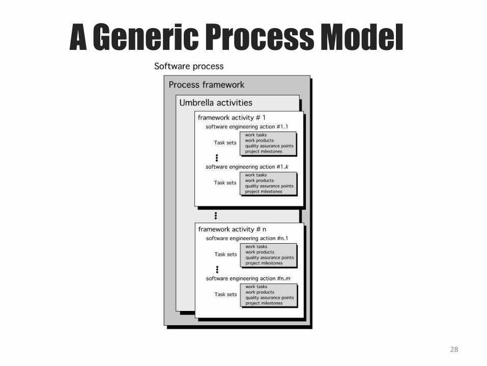
A Generic Process Model
28
A Generic Process ModelA generic process framework for software engineering defines
five framework activities- communication, planning,
modeling, construction, and deployment.
In addition, a set of umbrella activities- project tracking and control, risk management, quality assurance, configuration management, technical reviews, and others are applied throughout the process.
Next question is: how the framework activities and the actions and tasks that occur within each activity are organized with respect to sequence and time? See the process flow for answer.
29
Process Flow
30
7
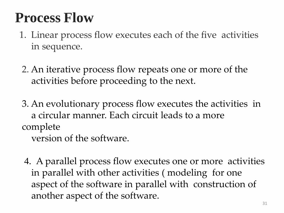
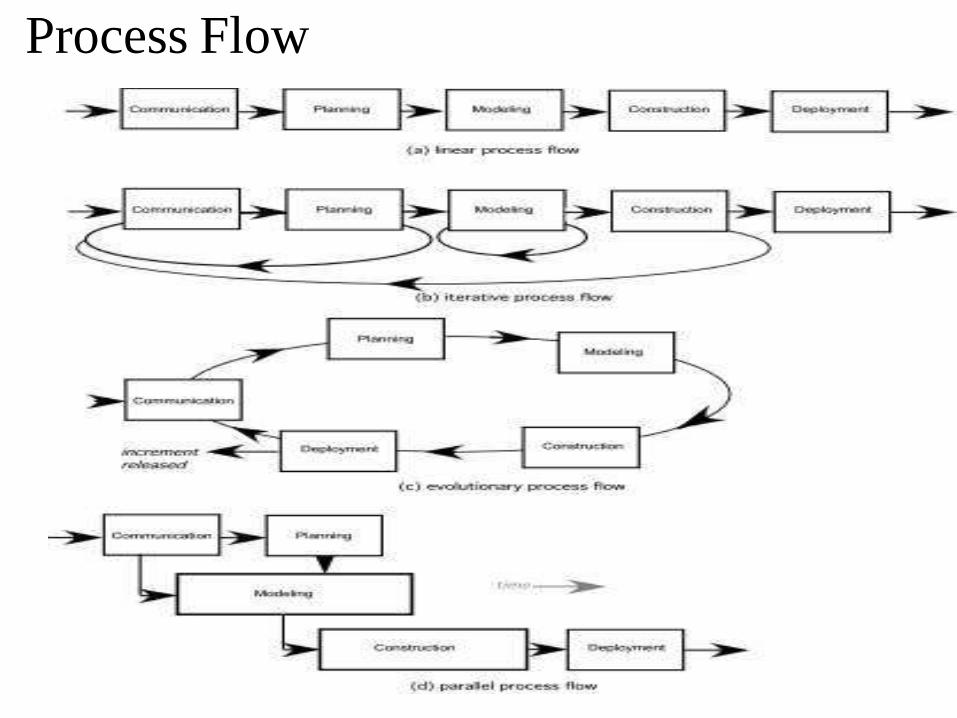
1. Linear process flow executes each of the five activities in sequence.
2. An iterative process flow repeats one or more of the activities before proceeding to the next.
3. An evolutionary process flow executes the activities in a circular manner. Each circuit leads to a more
complete version of the software.
4. A parallel process flow executes one or more activities in parallel with other activities ( modeling for one aspect of the software in parallel with construction of another aspect of the software.
31
Process Flow
Identifying a Task Set
Before you can proceed with the process model, a keyquestion: what actions are appropriate for a frameworkactivity given the nature of the problem, thecharacteristics of the people and the stakeholders?
32
A task set defines the actual work to be done to accomplishthe objectives of a software engineering action.
A list of the task to be accomplished
A list of the work products to be produced
A list of the quality assurance filters to be applied
Identifying a Task Set
For example, a small software project requested by oneperson with simple requirements, the communicationactivity might encompass little more than a phone allwith the stakeholder. Therefore, the only necessaryaction is phone conversation, the work tasks of thisaction are:
Make contact with stakeholder via telephone.
Discuss requirements and take notes.
Organize notes into a brief written statement of requirements.
E-mail to stakeholder for review and approval.
33
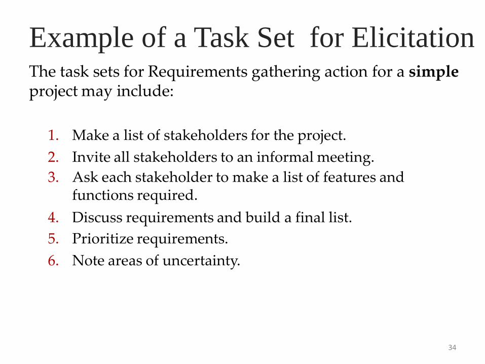
Example of a Task Set for ElicitationThe task sets for Requirements gathering action for a simple project may include:
34
1. Make a list of stakeholders for the project.
2. Invite all stakeholders to an informal meeting.
3. Ask each stakeholder to make a list of features and functions required.
4. Discuss requirements and build a final list.
5. Prioritize requirements.
6. Note areas of uncertainty.
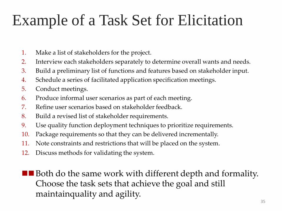
1. Make a list of stakeholders for the project.
2. Interview each stakeholders separately to determine overall wants and needs.
3. Build a preliminary list of functions and features based on stakeholder input.
4. Schedule a series of facilitated application specification meetings.
5. Conduct meetings.
6. Produce informal user scenarios as part of each meeting.
7. Refine user scenarios based on stakeholder feedback.
8. Build a revised list of stakeholder requirements.
9. Use quality function deployment techniques to prioritize requirements.
10. Package requirements so that they can be delivered incrementally.
11. Note constraints and restrictions that will be placed on the system.
12. Discuss methods for validating the system.
Both do the same work with different depth and formality. Choose the task sets that achieve the goal and still maintainquality and agility.
Example of a Task Set for Elicitation
35
Process Patterns• A process pattern
• describes a process-related problem that is encountered during software engineering work,
• identifies the environment in which the problem has been encountered, and
• suggests one or more proven solutions to the problem.
• Stated in more general terms, a process pattern provides you with atemplate [Amb98]—a consistent method for describing problem solutionswithin the context of the software process.
( defined at different levels of abstraction)
1. Problems and solutions associated with a complete process model (e.g. prototyping).
2. Problems and solutions associated with a framework activity (e.g. planning) or
3. an action with a framework activity (e.g. project estimating).
36
Process Pattern Types• Stage patterns—defines a problem associated with a
framework activity for the process. It includesmultiple task patterns as well. For example,EstablishingCommunication would incorporate thetask pattern RequirementsGathering and others.
• Task patterns—defines a problem associated with asoftware engineering action or work task andrelevant to successful software engineering practice
• Phase patterns—define the sequence of frameworkactivities that occur with the process, even when theoverall flow of activities is iterative in nature.Example includes SprialModel or Prototyping.
14
37
An Example of Process Pattern
38
• Describes an approach that may be applicable when stakeholders have a general idea of what must be done but are unsure of specific software requirements.
• Pattern name. Requirement Unclear
• Intent. This pattern describes an approach for building a model that can be assessediteratively by stakeholders in an effort to identify or solidify software requirements.
• Type. Phase pattern
• Initial context. Conditions must be met (1) stakeholders have been identified; (2) amode of communication between stakeholders and the software team has beenestablished; (3) the overriding software problem to be solved has been identified bystakeholders ; (4) an initial understanding of project scope, basic businessrequirements and project constraints has been developed.
• Problem. Requirements are hazy or nonexistent. stakeholders are unsure of what they want.
• Solution. A description of the prototyping process would be presented here.
• Resulting context. A software prototype that identifies basic requirements. (modesof interaction, computational features, processing functions) is approved bystakeholders. Following this, 1. This prototype may evolve through a series ofincrements to become the production software or 2. the prototype may be discarded.
• Related patterns. CustomerCommunication, IterativeDesign, IterativeDevelopment,
Customer Assessment, Requirement Extraction.
Process Assessment and Improvement• The existence of a software process is no guarantee that software will be
delivered on time, that it will meet the customer‟s needs, or that it will
exhibit the technical characteristics that will lead to long-term quality
characteristics.
• A number of different approaches to software process assessment and
improvement have been proposed over the past few decades:
• Standard CMMI Assessment Method for Process Improvement
(SCAMPI)—provides a five-step process assessment model that
incorporates five phases: initiating, diagnosing, establishing, acting, and
learning. The SCAMPI method uses the SEI CMMI as the basis for
assessment [SEI00].
• CMM-Based Appraisal for Internal Process Improvement (CBA
IPI)— provides a diagnostic technique for assessing the relative
maturity of a software organization; uses the SEI CMM as the basis for
the assessment [Dun01].
39
Process Assessment and Improvement• SPICE (ISO/IEC15504)—a standard that defines a set of
requirements for software process assessment. The intent of
the standard is to assist organizations in developing an
objective evaluation of the efficacy of any defined software
process [ISO08].
• ISO 9001:2000 for Software—a generic standard that applies
to any organization that wants to improve the overall quality of
the products, systems, or services that it provides. Therefore,
the standard is directly applicable to software organizations
and companies [Ant06].
40
Prescriptive Models
41
• Originally proposed to bring order to chaos.
• Prescriptive process models advocate an orderly approach to software
engineering. However, will some extent of chaos (less rigid) be beneficial
to bring some creativity?
That leads to a few questions …
• If prescriptive process models strive for structure and order (prescribe a set
of process elements and process flow), are they inappropriate for a
software world that thrives on change?
• Yet, if we reject traditional process models (and the order they imply) and
replace them with something less structured, do we make it impossible to
achieve coordination and coherence in software work?
42
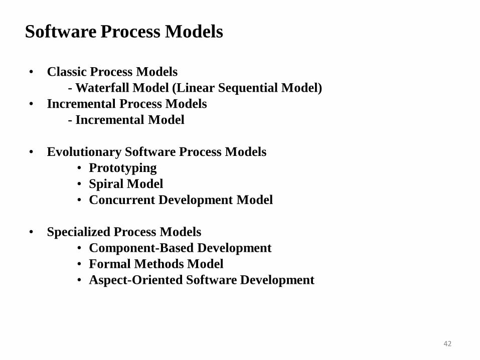
Software Process Models
• Classic Process Models
- Waterfall Model (Linear Sequential Model)
• Incremental Process Models
- Incremental Model
• Evolutionary Software Process Models
• Prototyping
• Spiral Model
• Concurrent Development Model
• Specialized Process Models
• Component-Based Development
• Formal Methods Model
• Aspect-Oriented Software Development
The Waterfall Model
43
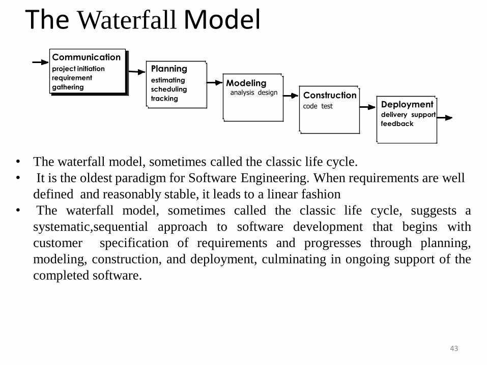
Modelinganalysis design Construction
code test
Communication
project initiation
requirement
gathering
Planning
estimating
scheduling
trackingDeploymentdelivery support
feedback
• The waterfall model, sometimes called the classic life cycle.
• It is the oldest paradigm for Software Engineering. When requirements are well
defined and reasonably stable, it leads to a linear fashion
• The waterfall model, sometimes called the classic life cycle, suggests a
systematic,sequential approach to software development that begins with
customer specification of requirements and progresses through planning,
modeling, construction, and deployment, culminating in ongoing support of the
completed software.
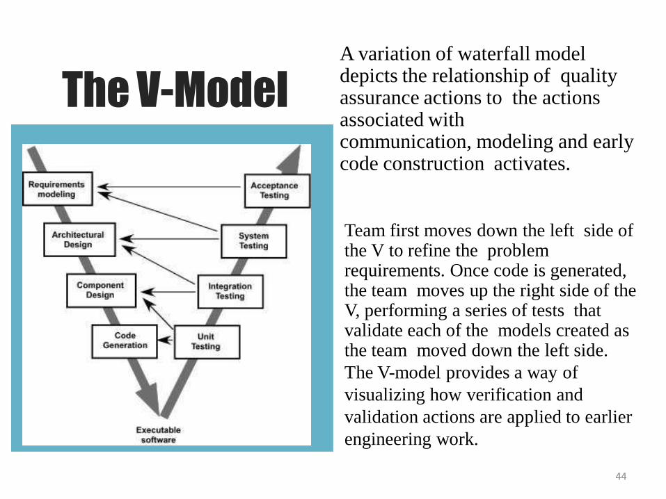
The V-ModelA variation of waterfall model depicts the relationship of quality assurance actions to the actions associated withcommunication, modeling and early code construction activates.
44
Team first moves down the left side of the V to refine the problem requirements. Once code is generated, the team moves up the right side of the V, performing a series of tests that validate each of the models created as the team moved down the left side.
The V-model provides a way of
visualizing how verification and
validation actions are applied to earlier
engineering work.
The problems that are sometimes encountered when the waterfall model is
applied are:
• Real projects rarely follow the sequential flow that the modelproposes. Although the linear model can accommodate iteration, itdoes so indirectly. As a result, changes can cause confusion as theproject team proceeds.
• It is often difficult for the customer to state all requirementsexplicitly. The waterfall model requires this and has difficultyaccommodating the natural uncertainty that exists at the beginningof many projects.
• The customer must have patience. A working version of theprogram(s) will not be available until late in the project time span. Amajor blunder, if undetected until the working program is reviewed,can be disastrous.
45
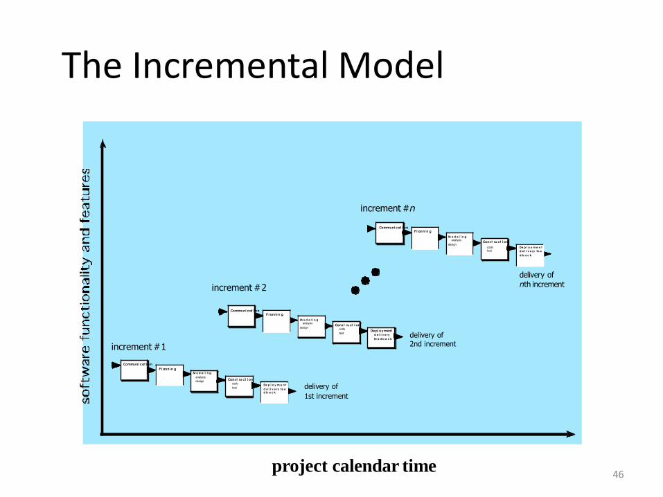
The Incremental Model
46
Co m m u n i c a t i on
P l a n n i n g
Co n s t ru c t i on
De p l o y m e n t
d e l i v e ry fe e d b a c k
M o d e l i n g
analysis
designcode
test
increment #1
increment #2
delivery of
1st increment
delivery of 2nd increment
delivery of
nth increment
increment #n
project calendar time
Co m m u n i c a t i onP l a n n i n g
Co n s t ru c t i on
De p l o y m e ntd e l i v e ry
fe e d b a c k
M o d e l i n g analysis
design code
test
Co m m u n i c a t i onP l a n n i n g
Co n s t ru c t i on
De p l o y m e n t
d e l i v e ry fe e
d b a c k
M o d e l i n g analysis
designcode test
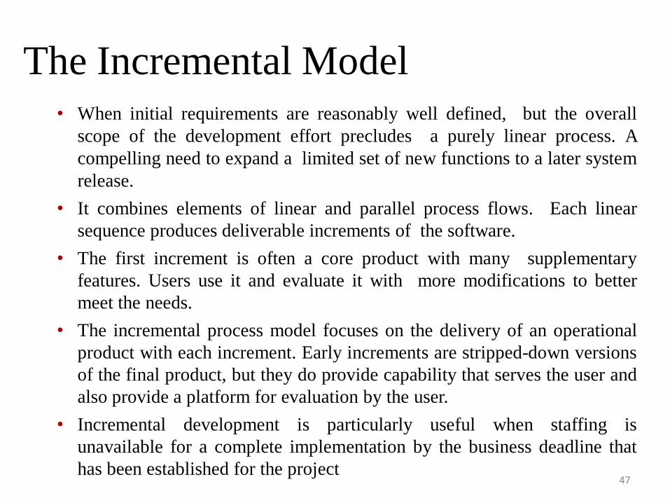
The Incremental Model
47
• When initial requirements are reasonably well defined, but the overall
scope of the development effort precludes a purely linear process. A
compelling need to expand a limited set of new functions to a later system
release.
• It combines elements of linear and parallel process flows. Each linear
sequence produces deliverable increments of the software.
• The first increment is often a core product with many supplementary
features. Users use it and evaluate it with more modifications to better
meet the needs.
• The incremental process model focuses on the delivery of an operational
product with each increment. Early increments are stripped-down versions
of the final product, but they do provide capability that serves the user and
also provide a platform for evaluation by the user.
• Incremental development is particularly useful when staffing is
unavailable for a complete implementation by the business deadline that
has been established for the project
Evolutionary Models
48
• Software system evolves over time as requirements often change
as development proceeds. Thus, a straight line to a complete end
product is not possible. However, a limited version must be
delivered to meet competitive pressure.
• Usually a set of core product or system requirements is well
understood, but the details and extension have yet to be defined.
• You need a process model that has been explicitly designed to
accommodate a product that evolved over time.
• It is iterative that enables you to develop increasingly more
complete version of the software.
• Two types are introduced, namely Prototyping and Spiral
models.
Evolutionary Models: Prototyping
49
• When to use: Customer defines a set of general objectives but does not identify
detailed requirements for functions and features. or Developer may be unsure of the
efficiency of an algorithm, the form that human computer interaction should take.
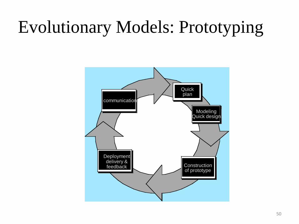
• What step: Begins with communication by meeting with stakeholders to define the
objective, identify whatever requirements are known, outline areas where further
definition is mandatory. A quick plan for prototyping and modeling (quick design)
occur. Quick design focuses on a representation of those aspects the software that will
be visible to end users. ( interface and output). Design leads to the construction of a
prototype which will be deployed and evaluated. Stakeholder’s comments will be
used to refine requirements.• Both stakeholders and software engineers like the prototyping paradigm. Users get a
feel for the actual system, and developers get to build something immediately.
However, engineers may make compromises in order to get a prototype working
quickly. The less-than-ideal choice may be adopted forever after you get used to it.
Evolutionary Models: Prototyping
50
Constructionof prototype
Com m u n ication
Q u ick p lan
Con stru ction
of
prototype
Mo d e lin g
Q u ick d e sig n
Deployment
De live ry
& Fe e dback
communication
Quick plan
Modeling Quick design
Construction of prototype
Deployment delivery & feedback
Prototyping can be problematic for the
following reasons:
51
• Stakeholders see what appears to be a working version of the software, unaware
that the prototype is held together haphazardly, unaware that in the rush to get it
working you haven‟t considered overall software quality or long-term
maintainability.
• As a software engineer, you often make implementation compromises in order to
get a prototype working quickly.
• An inappropriate operating system or programming language may be used simply
because it is available and known;
• An inefficient algorithm may be implemented simply to demonstrate capability.
After a time, you may become comfortable with these choices and forget all the
reasons why they were inappropriate. The less-than-ideal choice has now become
an integral part of the system
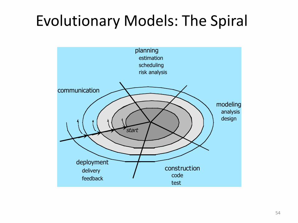
Evolutionary Models: The Spiral
52
• It couples the iterative nature of prototyping with the controlled and systematic
aspects of the waterfall model and is a risk-driven process model generator that is
used to guide multi-stakeholder concurrent engineering of software intensive
systems.
• Two main distinguishing features: one is cyclic approach for incrementally
growing a system‟s degree of definition and implementation while decreasing its
degree of risk. The other is a set of anchor point milestones for ensuring
stakeholder commitment to feasible and mutually satisfactory system solutions.
• A series of evolutionary releases are delivered. During the early iterations, the
release might be a model or prototype. During later iterations, increasingly more
complete version of the engineered system are produced.

• The first circuit in the clockwise direction might result in theproduct specification; subsequent passes around the spiralmight be used to develop a prototype and then progressivelymore sophisticated versions of the software.
• Each pass results in adjustments to the project plan. Costand schedule are adjusted based on feedback. Also, thenumber of iterations will be adjusted by project manager.
• Good to develop large-scale system as software evolves asthe process progresses and risk should be understood andproperly reacted to. Prototyping is used to reduce risk.
• However, it may be difficult to convince customers that it iscontrollable as it demands considerable risk assessmentexpertise.
53
Evolutionary Models: The Spiral
54
communication
deployment
delivery
feedback
start
modelinganalysis
design
constructioncode
test
planning estimation
scheduling
risk analysis
Three Concerns on
Evolutionary Processes
55
• First concern is that prototyping poses a problem to project planning because of
the uncertain number of cycles required to construct the product.
• Second, it does not establish the maximum speed of the evolution. If the
evolution occur too fast, without a period of relaxation, it is certain that the
process will fall into chaos. On the other hand if the speed is too slow then
productivity could be affected.
• Third, software processes should be focused on flexibility and extensibility
rather than on high quality. We should prioritize the speed of the development
over zero defects. Extending the development in order to reach high quality
could result in a late delivery of the product when the opportunity niche has
disappeared.
Concurrent Model
56
• Allow a software team to represent iterative and concurrent elements of any of the
process models. For example, the modeling activity defined for the spiral model is
accomplished by invoking one or more of the following actions: prototyping,
analysis and design.
• The Figure shows modeling may be in any one of the states at any given time. For
example, communication activity has completed its first iteration and in the
awaiting changes state. The modeling activity was in inactive state, now makes a
transition into the under development state. If customer indicates changes in
requirements, the modeling activity moves from the under development state into
the awaiting changes state.
• Concurrent modeling is applicable to all types of software development and
provides an accurate picture of the current state of a project. Rather than confining
software engineering activities, actions and tasks to a sequence of events, it defines
a process network. Each activity, action or task on the network exists
simultaneously with other activities, actions or tasks. Events generated at one point
trigger transitions among28the state.
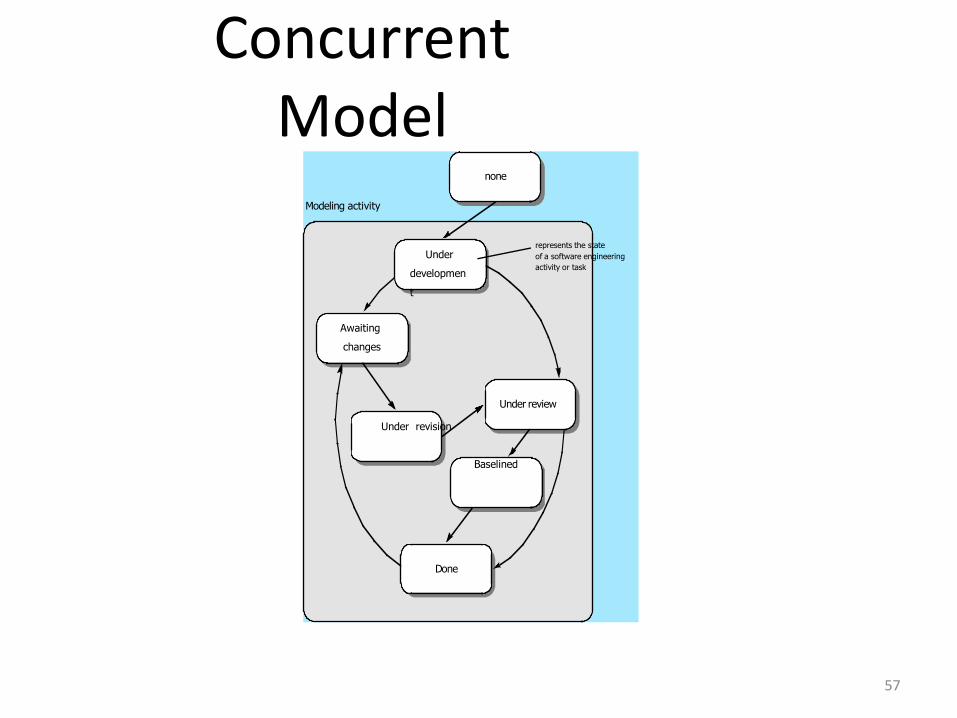
ConcurrentModel
57
Under review
Done
Under revision
Baselined
Awaiting
changes
Under
developmen
t
none
Modeling activity
represents the state
of a software engineering
activity or task
58
SPECIALIZED PROCESS MODELS
•Component-Based Development
•The Formal Methods Model
•Aspect-Oriented Software Development
58
59
SPECIALIZED PROCESS MODELS
•Component-Based DevelopmentCommercial off-the-shelf (COTS) software components, developed by vendors
who offer them as products, provide targeted functionality with well-defined
interfaces that enable the component to be integrated into the software that is to
be built.
These components can be as either conventional software modules or object-
oriented packages or packages of classes
• Steps involved in CBS are
• Available component-based products are researched
and evaluated for the application domain in
question.
• Component Integration issues are considered.
59
60
SPECIALIZED PROCESS MODELS
•Component-Based Development
• Steps involved in CBS are
• A software architecture is designed to accommodate
the components
• Components are integrated into the architecture
• Comprehensive testing is conducted to ensure
proper functionality
The component-based development model leads to software
reuse, and reusability provides software engineers with a
number of measurable benefits60
61
SPECIALIZED PROCESS MODELS
•Component-Based Development
• Component-based development model leads to
software reuse and reusability helps software
engineers with a number of measurable benefits
• Component-based development leads to a 70 percent
reduction in development cycle time, 84 percent
reduction in project cost and productivity index of 26.2
compared to an industry norm of 16.9
61
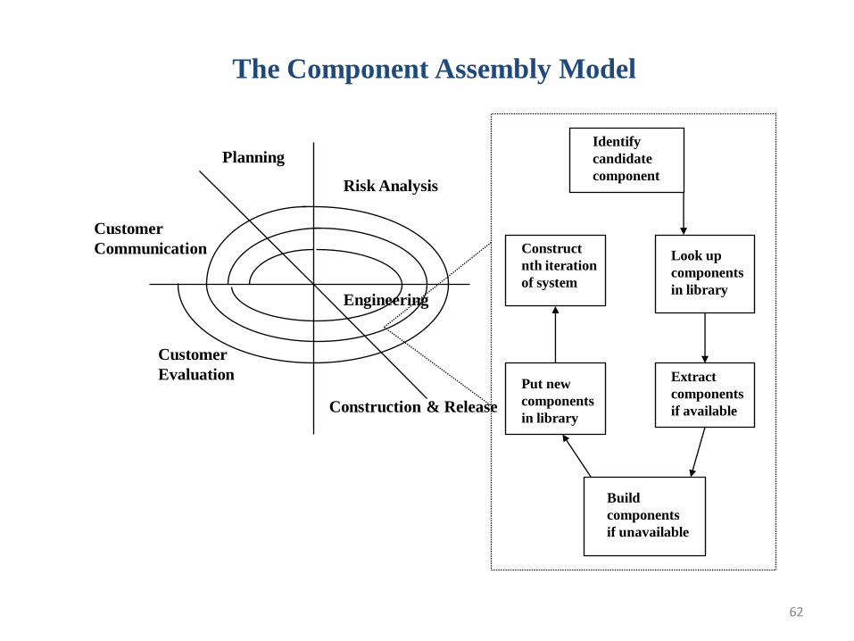
62
The Component Assembly Model
Construction & Release
Risk Analysis
Planning
Customer
Evaluation
Customer
Communication
Identify
candidate
component
Build
components
if unavailable
Put new
components
in library
Extract
components
if available
Construct
nth iteration
of system
Look up
components
in libraryEngineering
63
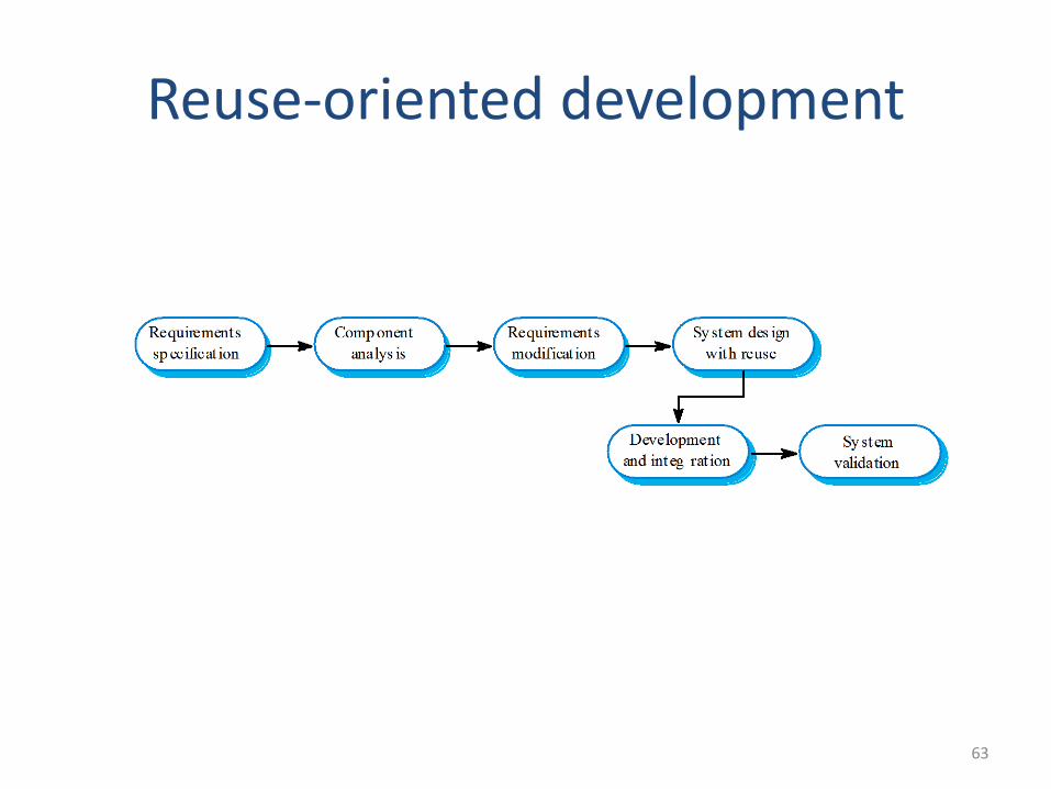
Reuse-oriented development
64
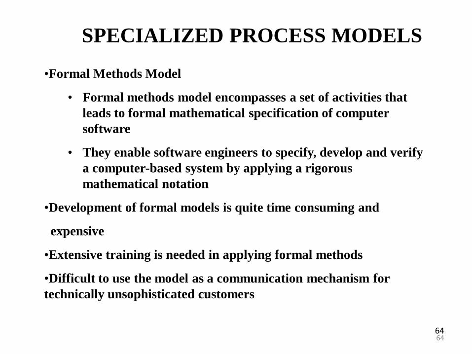
SPECIALIZED PROCESS MODELS
•Formal Methods Model
• Formal methods model encompasses a set of activities that
leads to formal mathematical specification of computer
software
• They enable software engineers to specify, develop and verify
a computer-based system by applying a rigorous
mathematical notation
•Development of formal models is quite time consuming and
expensive
•Extensive training is needed in applying formal methods
•Difficult to use the model as a communication mechanism for
technically unsophisticated customers
64
65
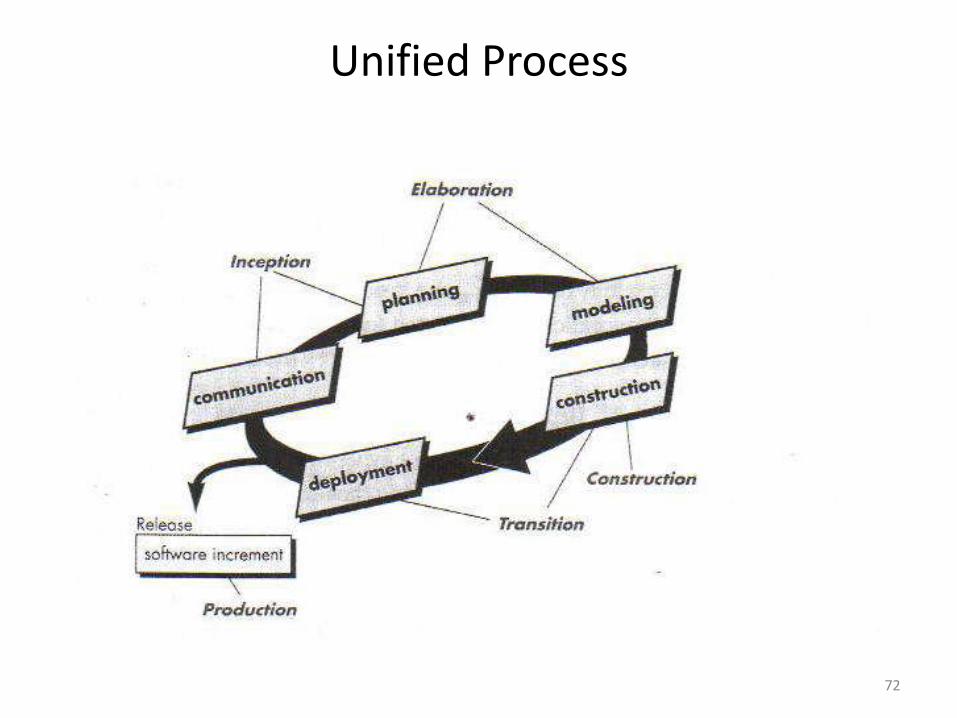
Unified Process
• The Unified Process is an iterative and incremental developmentprocess. Unified Process divides the project into four phases – Inception– Elaboration– Construction– Transition
• The Inception, Elaboration, Construction and Transition phases are divided into a series of timeboxed iterations. (The Inception phase may also be divided into iterations for a large project.)
• Each iteration results in an increment, which is a release of the system that contains added or improved functionality compared with the previous release.
• Although most iterations will include work in most of the process disciplines (e.g. Requirements, Design, Implementation, Testing) the relative effort and emphasis will change over the course of the project.
66
Unified Process
• Risk Focused
– The Unified Process requires the project team to focus on addressing the most critical risks early in the project life cycle. The deliverables of each iteration, especially in the Elaboration phase, must be selected in order to ensure that the greatest risks are addressed first. Risk Focused
67
Unified Process
• Inception Phase– Inception is the smallest phase in the project, and ideally it should
be quite short. If the Inception Phase is long then it is usually an indication of excessive up-front specification, which is contrary to the spirit of the Unified Process.
– The following are typical goals for the Inception phase.
• Establish a justification or business case for the project
• Establish the project scope and boundary conditions
• Outline the use cases and key requirements that will drive the design tradeoffs
• Outline one or more candidate architectures
• Identify risks
• Prepare a preliminary project schedule and cost estimate
– The Lifecycle Objective Milestone marks the end of the Inception phase.
68
Unified Process
• Elaboration Phase
– During the Elaboration phase the project team is expected to capture a majority of the system requirements. The primary goals of Elaboration are to address known risk factors and to establish and validate the system architecture.
– Common processes undertaken in this phase include the creation of use case diagrams, conceptual diagrams (class diagrams with only basic notation) and package diagrams (architectural diagrams).
– The architecture is validated primarily through the implementation of an Executable Architectural Baseline. This is a partial implementation of the system which includes the core, most architecturally significant, components. It is built in a series of small, timeboxed iterations.
69
Unified Process
• Elaboration Phase
– By the end of the Elaboration phase the system architecture must have stabilized and the executable architecture baseline must demonstrate that the architecture will support the key system functionality and exhibit the right behavior in terms of performance, scalability and cost.
– The final Elaboration phase deliverable is a plan (including cost
and schedule estimates) for the Construction phase. At this point
the plan should be accurate and credible, since it should be based
on the Elaboration phase experience and since significant risk
factors should have been addressed during the Elaboration phase.
– The Lifecycle Architecture Milestone marks the end of the
Elaboration phase.
70
Unified Process
• Construction Phase– Construction is the largest phase in the project. In this phase the
remainder of the system is built on the foundation laid in Elaboration. System features are implemented in a series of short, timeboxed iterations. Each iteration results in an executable release of the software. It is customary to write full text use cases during the construction phase and each one becomes the start of a new iteration.
– Common UML (Unified Modeling Language) diagrams used during this phase include Activity, Sequence, Collaboration, State (Transition) and Interaction Overview diagrams.
– The Initial Operational Capability Milestone marks the end of the Construction phase.
71
Unified Process• Transition Phase
– The final project phase is Transition. In this phase the
system is deployed to the target users. Feedback
received from an initial release (or initial releases) may
result in further refinements to be incorporated over
the course of several Transition phase iterations. The
Transition phase also includes system conversions and
user training.
– The Product Release Milestone marks the end of the
Transition phase.
72
Unified Process
73
Unified Process
• Advantages of UP Software Development
– This is a complete methodology in itself with an emphasis on accurate documentation
– It is proactively able to resolve the project risks associated with the client's evolving requirements requiring careful change request management
– Less time is required for integration as the process of integration goes on throughout the software development life cycle.
– The development time required is less due to reuse of components.
74
Unified Process
• Disadvantages of RUP Software Development– The team members need to be expert in their field to
develop a software under this methodology. – On cutting edge projects which utilise new technology,
the reuse of components will not be possible. Hence the time saving one could have made will be impossible to fulfill.
– Integration throughout the process of software development, in theory sounds a good thing. But on particularly big projects with multiple development streams it will only add to the confusion and cause more issues during the stages of testing
What is estimation?
Estimation is attempt to determine how much money, effort, resources & time it
will take to build a specific software based system or project.
Estimation involves answering the following questions:
1. How much effort is required to complete each activity?
2. How much calendar time is needed to complete each activity?
3. What is the total cost of each activity?
Project cost estimation and project scheduling are normallycarried out together.
The costs of development are primarily the costs of theeffort involved, so the effort computation is used in both thecost and the schedule estimate.
Do some cost estimation before detailed schedules aredrawn up.
These initial estimates may be used to establish a budget forthe project or to set a price for the software for a customer
There are three parameters involved in computing the total cost of
a software development project:
• Hardware and software costs including maintenance
• Travel and training costs
• Effort costs (the costs of paying software engineers).
The following costs are all part of the total effort cost:
1. Costs of providing, heating and lighting office space
2. Costs of support staff such as accountants, administrators,
system managers, cleaners and technicians
3. Costs of networking and communications
4. Costs of central facilities such as a library or recreational
facilities
5. Costs of Social Security and employee benefits such as
pensions and health insurance.
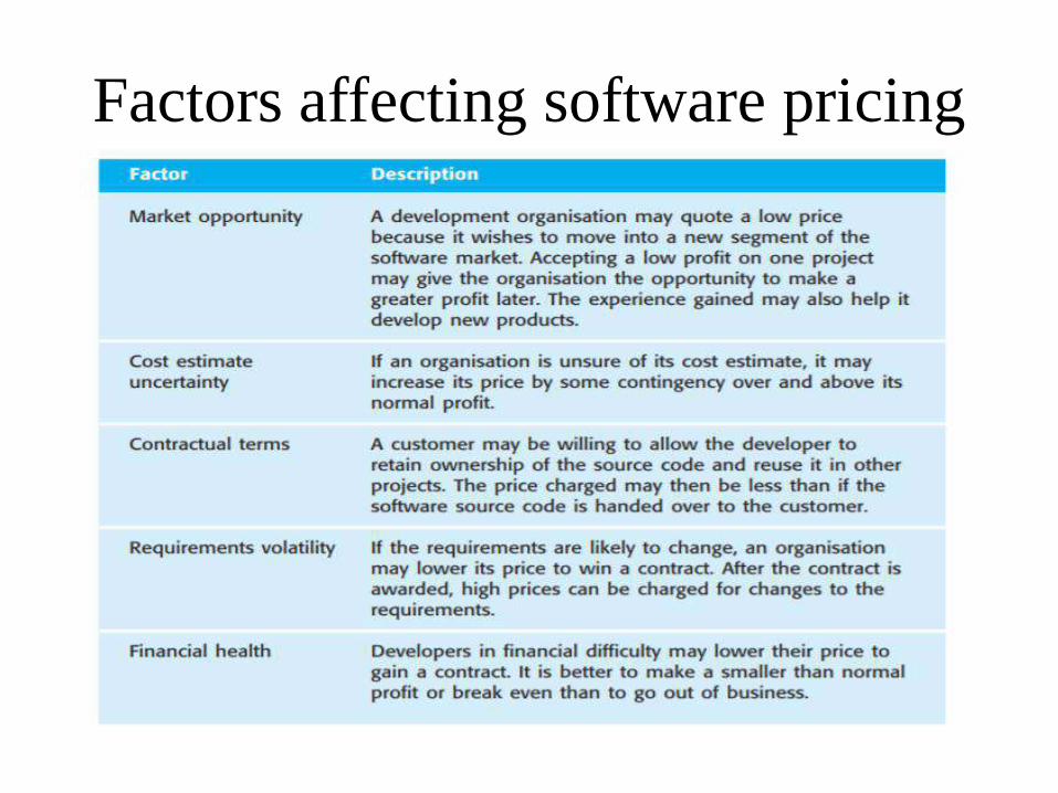
Factors affecting software pricing
78
COCOMO Models MotivationThe software cost estimation provides:
• The vital link between the general concepts and techniques of economic analysisand the particular world of software engineering.
• Software cost estimation techniques also provides an essential part of thefoundation for good software management.
Cost of a project
• The cost in a project is due to:
– due the requirements for software, hardware and human resources
– the cost of software development is due to the human resources needed
– most cost estimates are measured in person-months (PM)
– the cost of the project depends on the nature and characteristics of the project, at any point, the accuracy of the estimate will depend on the amount of reliable information we have about the final product.
79
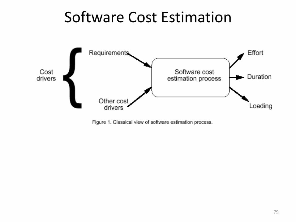
Software Cost Estimation
80
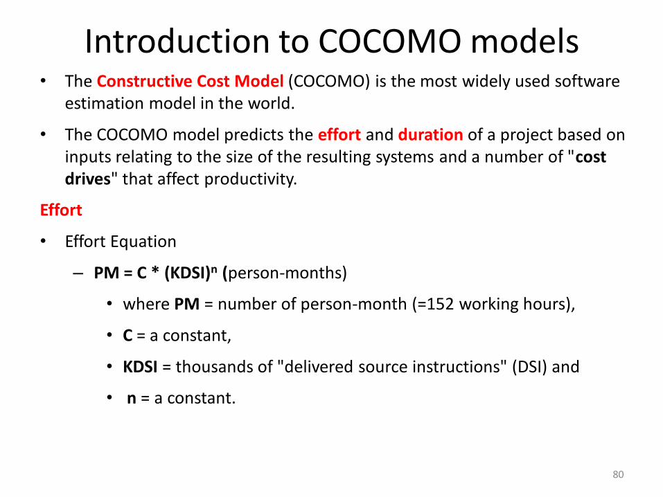
Introduction to COCOMO models• The Constructive Cost Model (COCOMO) is the most widely used software
estimation model in the world.
• The COCOMO model predicts the effort and duration of a project based on inputs relating to the size of the resulting systems and a number of "cost drives" that affect productivity.
Effort
• Effort Equation
– PM = C * (KDSI)n (person-months)
• where PM = number of person-month (=152 working hours),
• C = a constant,
• KDSI = thousands of "delivered source instructions" (DSI) and
• n = a constant.
81
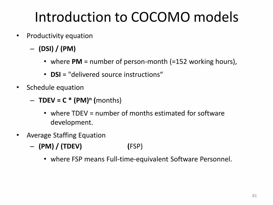
Introduction to COCOMO models• Productivity equation
– (DSI) / (PM)
• where PM = number of person-month (=152 working hours),
• DSI = "delivered source instructions“
• Schedule equation
– TDEV = C * (PM)n (months)
• where TDEV = number of months estimated for software development.
• Average Staffing Equation
– (PM) / (TDEV) (FSP)
• where FSP means Full-time-equivalent Software Personnel.
82
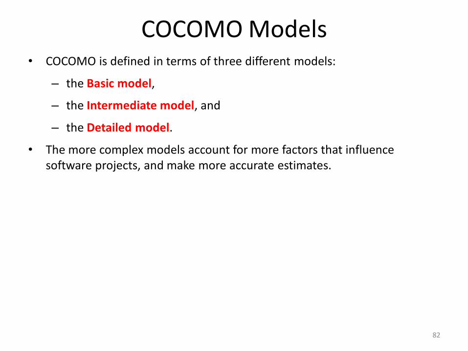
COCOMO Models• COCOMO is defined in terms of three different models:
– the Basic model,
– the Intermediate model, and
– the Detailed model.
• The more complex models account for more factors that influence software projects, and make more accurate estimates.
83
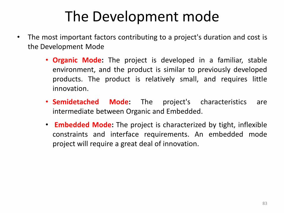
The Development mode• The most important factors contributing to a project's duration and cost is
the Development Mode
• Organic Mode: The project is developed in a familiar, stableenvironment, and the product is similar to previously developedproducts. The product is relatively small, and requires littleinnovation.
• Semidetached Mode: The project's characteristics areintermediate between Organic and Embedded.
• Embedded Mode: The project is characterized by tight, inflexibleconstraints and interface requirements. An embedded modeproject will require a great deal of innovation.
84
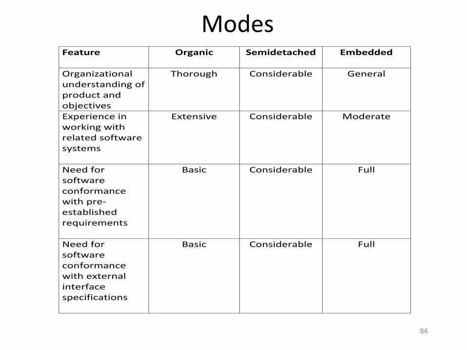
Modes Feature
Organic Semidetached Embedded
Organizational understanding of product and objectives
Thorough
Considerable
General
Experience in working with related software systems
Extensive
Considerable
Moderate
Need for software conformance with pre-established requirements
Basic
Considerable
Full
Need for software conformance with external interface specifications
Basic
Considerable
Full
85
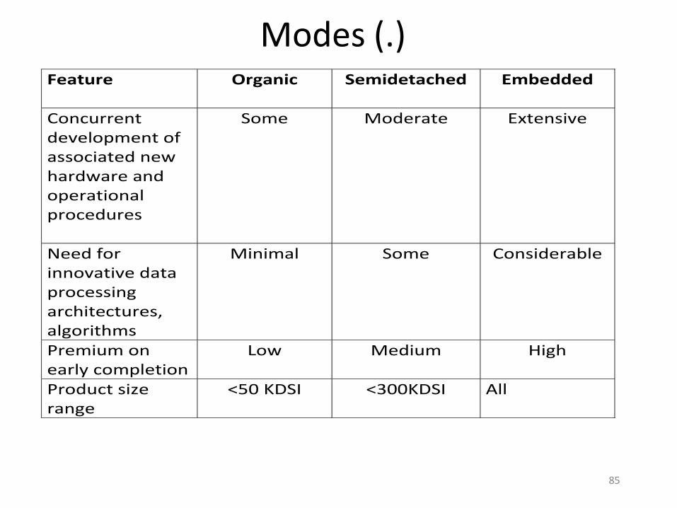
Modes (.) Feature
Organic Semidetached Embedded
Concurrent development of associated new hardware and operational procedures
Some
Moderate
Extensive
Need for innovative data processing architectures, algorithms
Minimal
Some
Considerable
Premium on early completion
Low
Medium
High
Product size range
<50 KDSI
<300KDSI
All
86
Cost Estimation Process
Cost= Size Of The Project x Productivity
87
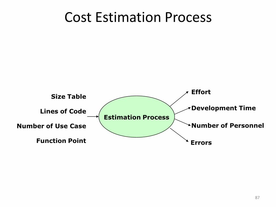
Cost Estimation Process
Errors
Effort
Development Time
Size Table
Lines of Code
Number of Use Case
Function Point
Estimation Process
Number of Personnel
88
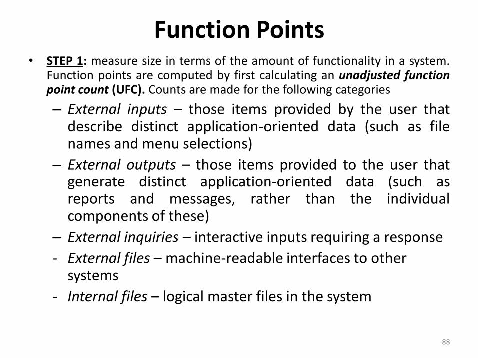
Function Points• STEP 1: measure size in terms of the amount of functionality in a system.
Function points are computed by first calculating an unadjusted functionpoint count (UFC). Counts are made for the following categories
– External inputs – those items provided by the user thatdescribe distinct application-oriented data (such as filenames and menu selections)
– External outputs – those items provided to the user thatgenerate distinct application-oriented data (such asreports and messages, rather than the individualcomponents of these)
– External inquiries – interactive inputs requiring a response
- External files – machine-readable interfaces to other systems
- Internal files – logical master files in the system
89
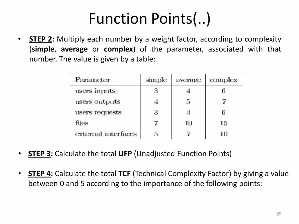
Function Points(..)• STEP 2: Multiply each number by a weight factor, according to complexity
(simple, average or complex) of the parameter, associated with thatnumber. The value is given by a table:
• STEP 3: Calculate the total UFP (Unadjusted Function Points)
• STEP 4: Calculate the total TCF (Technical Complexity Factor) by giving a valuebetween 0 and 5 according to the importance of the following points:
90
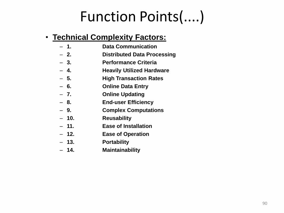
Function Points(....)• Technical Complexity Factors:
– 1. Data Communication
– 2. Distributed Data Processing
– 3. Performance Criteria
– 4. Heavily Utilized Hardware
– 5. High Transaction Rates
– 6. Online Data Entry
– 7. Online Updating
– 8. End-user Efficiency
– 9. Complex Computations
– 10. Reusability
– 11. Ease of Installation
– 12. Ease of Operation
– 13. Portability
– 14. Maintainability
91
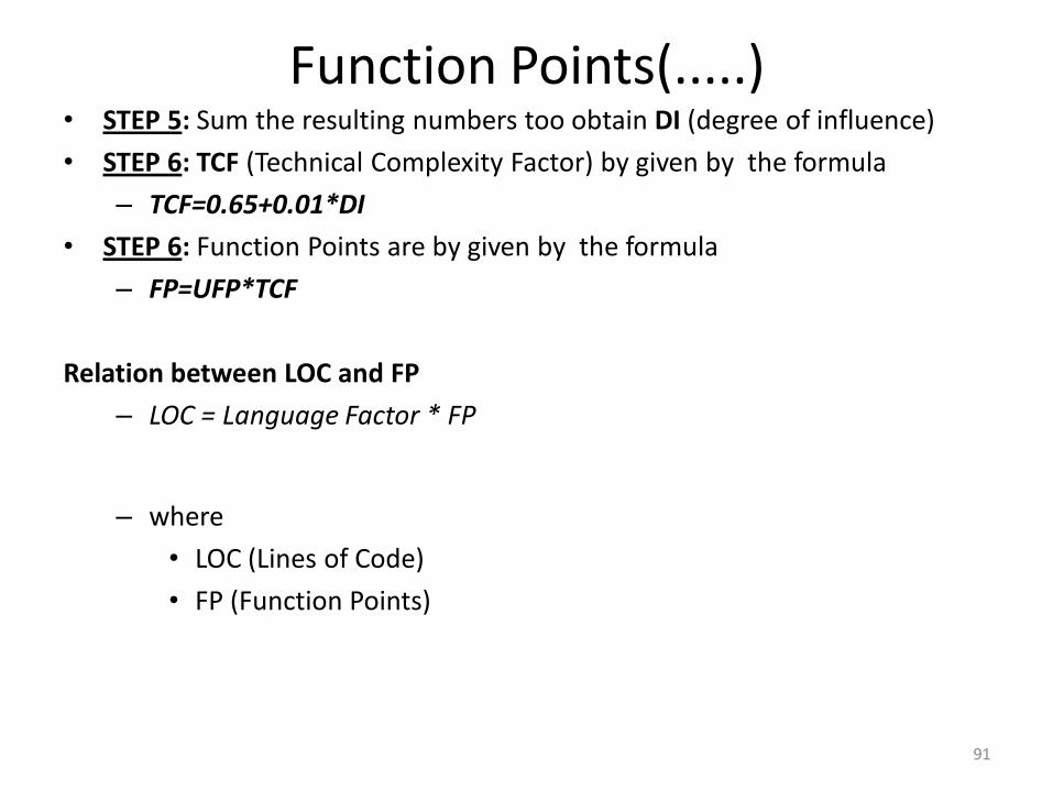
Function Points(.....)• STEP 5: Sum the resulting numbers too obtain DI (degree of influence)
• STEP 6: TCF (Technical Complexity Factor) by given by the formula
– TCF=0.65+0.01*DI
• STEP 6: Function Points are by given by the formula
– FP=UFP*TCF
Relation between LOC and FP
– LOC = Language Factor * FP
– where
• LOC (Lines of Code)
• FP (Function Points)
92
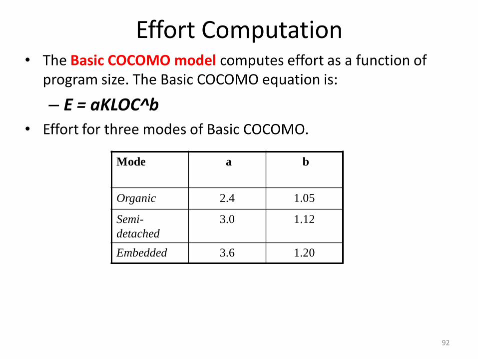
Effort Computation• The Basic COCOMO model computes effort as a function of
program size. The Basic COCOMO equation is:
– E = aKLOC^b
• Effort for three modes of Basic COCOMO.
Mode a b
Organic 2.4 1.05
Semi-
detached
3.0 1.12
Embedded 3.6 1.20
93
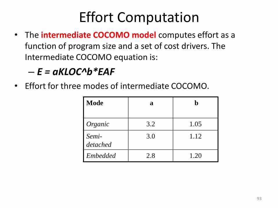
Effort Computation• The intermediate COCOMO model computes effort as a
function of program size and a set of cost drivers. The Intermediate COCOMO equation is:
– E = aKLOC^b*EAF
• Effort for three modes of intermediate COCOMO.
Mode a b
Organic 3.2 1.05
Semi-
detached
3.0 1.12
Embedded 2.8 1.20
94
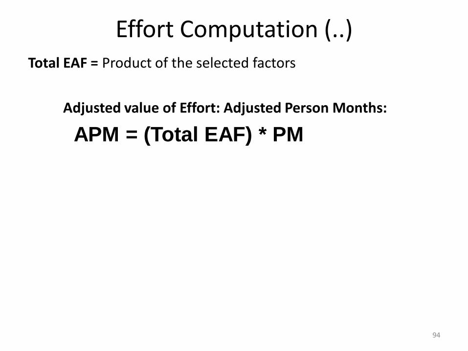
Effort Computation (..)Total EAF = Product of the selected factors
Adjusted value of Effort: Adjusted Person Months:
APM = (Total EAF) * PM
95
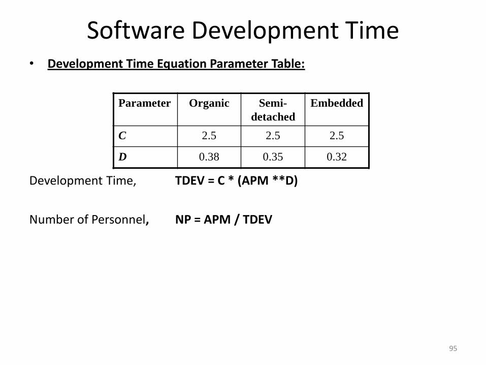
Software Development Time• Development Time Equation Parameter Table:
Development Time, TDEV = C * (APM **D)
Number of Personnel, NP = APM / TDEV
Parameter Organic Semi-
detached
Embedded
C 2.5 2.5 2.5
D 0.38 0.35 0.32
96
Distribution of Effort• A development process typically consists of the following stages:
• Requirements Analysis
• Design (High Level + Detailed)
• Implementation & Coding
• Testing (Unit + Integration)
97
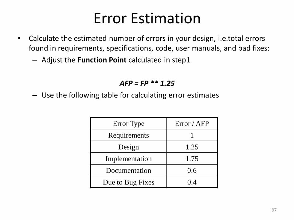
Error Estimation• Calculate the estimated number of errors in your design, i.e.total errors
found in requirements, specifications, code, user manuals, and bad fixes:
– Adjust the Function Point calculated in step1
AFP = FP ** 1.25
– Use the following table for calculating error estimates
Error Type Error / AFP
Requirements 1
Design 1.25
Implementation 1.75
Documentation 0.6
Due to Bug Fixes 0.4
Estimation• LOC based estimation
• Source lines of code (SLOC), also known as lines of code (LOC), is a software metric used to measure the size of a computer program by counting the number of lines in the text of the program's source code.
• SLOC is typically used to predict the amount of effort that will be required to developa program, as well as to estimate programming productivity or maintainability oncethe software is produced.
• Lines used for commenting the code and header file are ignored.
• Two major types of LOC:
1. Physical LOC
• Physical LOC is the count of lines in the text of the program's source code includingcomment lines.
• Blank lines are also included unless the lines of code in a section consists of morethan 25% blank lines.
2. Logical LOC
• Logical LOC attempts to measure the number of executable statements, but theirspecific definitions are tied to specific computer languages.
• Ex: Logical LOC measure for C-like programming languages is the number ofstatement-terminating semicolons(;)
EstimationLOC‐based Estimation
The problems of lines of code (LOC)– Different languages lead to different lengths of code– It is not clear how to count lines of code– A report, screen, or GUI generator can generate thousands of lines of code
in minutes– Depending on the application, the complexity of code is different.
PROJECT SCHEDULING
100
What is PROJECT SCHEDULING?
Basic Concepts
Project Scheduling
• Basic Principles
• The Relationship Between People and Effort
• Effort Distribution
•Earned Value Analysis
What is PROJECT SCHEDULING?
• In the late 1960s, a bright-eyed young engineer was chosen to“write” a computer program for an automated manufacturingapplication. The reason for his selection was simple. He was theonly person in his technical group who had attended a computerprogramming seminar. He knew the ins and outs of assemblylanguage and FORTRAN but nothing about software engineeringand even less about project scheduling and tracking. His boss gavehim the appropriate manuals and a verbal description of what had tobe done. He was informed that the project must be completed in twomonths. He read the manuals, considered his approach, and beganwriting code. After two weeks, the boss called him into his officeand asked how things were going. “Really great,” said the youngengineer with youthful enthusiasm. “This was much simpler than Ithought. I‟m probably close to 75 percent finished.”
101
What is PROJECT SCHEDULING?
• The boss smiled and encouraged the young engineer to keep up thegood work. They planned to meet again in a week‟s time. A weeklater the boss called the engineer into his office and asked, “Wherearewe?” “Everything‟s going well,” said the youngster, “but I‟ve runinto a few small snags. I‟ll get them ironed out and be back on tracksoon.” “How does the deadline look?” the boss asked. “Noproblem,” said the engineer. “I‟m close to 90 percent complete.” Ifyou‟ve been working in the software world for more than a fewyears, you can finish the story. It‟ll come as no surprise that theyoung engineer1 stayed 90 percent complete for the entire projectduration and finished (with the help of others) only one month late.This story has been repeated tens of thousands of times by softwaredevelopers during the past five decades. The big question is why?
102
What is PROJECT SCHEDULING? You’ve selected an app You’ve selected an appropriate process model
Appropriate process model.
You’ve identified the software engineering tasks that have to beperformed.
You estimated the amount of work and the number of people, you knowthe deadline, you’ve even considered the risks.
Now it’s time to connect the dots. That is, you have to create a network ofsoftware engineering tasks that will enable you to get the job done ontime.
Once the network is created, you have to assign responsibility for eachtask, make sure it gets done, and adapt the network as risks becomereality.
103
What is PROJECT SCHEDULING?
104
Why it’s Important? In order to build a complex system, many software engineering tasks
occur in parallel. The result of work performed during one task may have a profound
effect on work to be conducted in another task. These interdependencies are very difficult to understand without a
schedule. lt’s also virtually impossible to assess progress on a moderate or large
software project without a detailed schedule
What are the steps?
The software engineering tasks dictated by the software process model are refined for the functionality to be built.
Effort and duration are allocated to each task and a task network (also called an “activity network”) is created in a manner that enables the software team to meet the delivery deadline established.
What is PROJECT SCHEDULING?Basic Concept of Project Scheduling
An unrealistic deadline established by someone outside the software development group and forced on managers and practitioner's within the group.
Changing customer requirements that are not reflected in schedule changes.
An honest underestimate of the amount of effort and/or the number of resources that will be required to do the job.
Predictable and/or unpredictable risks that were not considered when the project commenced.
Technical difficulties that could not have been foreseen in advance.
Why should we do when the management demands that we make a dead line I impossible? Perform a detailed estimate using historical data from past projects.
Determine the estimated effort and duration for the project.
Using an incremental process model, develop a software engineering strategy that will deliver critical functionality by the imposed deadline, but delay other functionality until later. Document the plan.
Meet with the customer and (using the detailed estimate), explain why the imposed deadline is unrealistic.
105
Project Scheduling
106
Project Scheduling
• Basic Principles
• The Relationship Between People and Effort
• Effort Distribution
• Software project scheduling is an action that distributes estimated effort across the
planned project duration by allocating the effort to specific software engineering
tasks.
• During early stages of project planning, a macroscopic schedule is developed.
• As the project gets under way, each entry on the macroscopic schedule is refined
into a detailed schedule.
Project Scheduling Basic Principles of Project Scheduling.
1. Compartmentalization: The project must be compartmentalized into a number of manageable activities and tasks. To accomplish compartmentalization, both the product and the process are refined.
2. Interdependency: The interdependency of each compartmentalized activity ortask must be determined. Some tasks must occur in sequence, while otherscan occur in parallel. Other activities can occur independently.
3. Time allocation: Each task to be scheduled must be allocated some number ofwork units (e.g., person‐days of effort). In addition, each task must beassigned a start date and a completion date. whether work will be conductedon a full-time or part-time basis.
4. Effort validation: Every project has a defined number of people on thesoftware team. The project manager must ensure that no more than theallocated number of people have been scheduled at any given time.
5. Defined responsibilities. Every task that is scheduled should be assigned to aspecific team member.
107
Project Scheduling6. Defined outcomes: Every task that is scheduled should have a defined
outcome. For software projects, the outcome is normally a work product (e.g., the design of a component) or a part of a work product. Work products are often combined in deliverables.
7. Defined milestones: Every task or group of tasks should be associated with a project milestone. A milestone is accomplished when one or more work products has been reviewed for quality and has been approved.
Each of these principles is applied as the project schedule evolves.
108
The Relationship Between People and Effort
• In a small software development project a single person can analyzerequirements, perform design, generate code, and conduct tests. As the size of aproject increases, more people must become involved.
•There is a common myth that is still believed by many managers who areresponsible for software development projects: “If we fall behind schedule, wecan always add more programmers and catch up later in the project.”
•Unfortunately, adding people late in a project often has a disruptive effect on theproject, causing schedules to slip even further. The people who are added mustlearn the system, and the people who teach them are the same people whowere doing the work.
•While teaching, no work is done, and the project falls further behind. In additionto the time it takes to learn the system, more people.
•Although communication is absolutely essential to successful softwaredevelopment, every new communication path requires additional effort andtherefore additional time.
109
Effort Distribution • A recommended distribution of effort across the software process is oftenreferred to as the 40–20–40 rule.
•Forty percent of all effort is allocated to frontend analysis and design. A similarpercentage is applied to back-end testing. You can correctly infer that coding (20percent of effort) is deemphasized.
• Work expended on project planning rarely accounts for more than 2 to 3 percentof effort, unless the plan commits an organization to large expenditures with highrisk.
•Customer communication and requirements analysis may comprise 10 to 25percent of project effort.
•Effort expended on analysis or prototyping should increase in direct proportionwith project size and complexity.
•A range of 20 to 25 percent of effort is normally applied to software design. Timeexpended for design review and subsequent iteration must also be considered.
110
• Because of the effort applied to software design, code shouldfollow with relatively little difficulty.
• A range of 15 to 20 percent of overall effort can be achieved.Testing and subsequent debugging can account for 30 to 40 percentof software development effort.
• The criticality of the software often dictates the amount of testingthat is required. If software is human rated (i.e., software failurecan result in loss of life), even higher percentages are typical.
111
Scheduling • Scheduling of a software project does not differ greatly from scheduling of
any multitask engineering effort. Therefore, generalized project schedulingtools and techniques can be applied with little modification for softwareprojects.
• Program evaluation and review technique (PERT) and the critical pathmethod (CPM) are two project scheduling methods that can be applied tosoftware development.
1. Time-Line Charts:
• When creating a software project schedule, begin with a set of tasks.
• If automated tools are used, the work breakdown is input as a tasknetwork or task outline. Effort, duration, and start date are then input foreach task. In addition, tasks may be assigned to specific individuals.
• As a consequence of this input, a time-line chart, also called a Gantt chart,is generated.
• A time-line chart can be developed for the entire project. Alternatively,separate charts can be developed for each project function or for eachindividual working on the project.
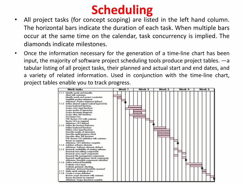
Scheduling • All project tasks (for concept scoping) are listed in the left hand column.
The horizontal bars indicate the duration of each task. When multiple barsoccur at the same time on the calendar, task concurrency is implied. Thediamonds indicate milestones.
• Once the information necessary for the generation of a time-line chart has beeninput, the majority of software project scheduling tools produce project tables. —atabular listing of all project tasks, their planned and actual start and end dates, anda variety of related information. Used in conjunction with the time-line chart,project tables enable you to track progress.
Scheduling 2. Tracking the Schedule
• If it has been properly developed, the project schedule becomes a roadmap that defines the tasks and milestones to be tracked and controlled asthe project proceeds.
• Tracking can be accomplished in a number of different ways:
• Conducting periodic project status meetings in which each team memberreports progress and problems.
• Evaluating the results of all reviews conducted throughout the softwareengineering process.
• Determining whether formal project milestones have been accomplishedby the scheduled date.
• Comparing the actual start date to the planned start date for each projecttask listed in the resource table.
• Meeting informally with practitioners to obtain their subjectiveassessment of progress to date and problems on the horizon.
• Using earned value analysis to assess progress quantitatively.
In reality, all of these tracking techniques are used by experienced projectmanagers.

Scheduling
3. Tracking Progress for an OO Project
Technical milestone: OO analysis complete
o All hierarchy classes defined and reviewed
o Class attributes and operations are defined and reviewed
o Class relationships defined and reviewed
o Behavioral model defined and reviewed
o Reusable classed identified
Technical milestone: OO design complete
o Subsystems defined and reviewed
o Classes allocated to subsystems and reviewed
o Task allocation has been established and reviewed
o Responsibilities and collaborations have been identified
o Attributes and operations have been designed and reviewed
o Communication model has been created and reviewed

Scheduling
• Technical milestone: OO programming complete
o Each new design model class has been implemented
o Classes extracted from the reuse library have been implemented
o Prototype or increment has been built
• Technical milestone: OO testing
o The correctness and completeness of the OOA and OOD models hasbeen reviewed
o Class-responsibility-collaboration network has been developed andreviewed
o Test cases are designed and class-level tests have been conducted foreach class
o Test cases are designed, cluster testing is completed, and classes havebeen integrated
o System level tests are complete

Scheduling 4. Scheduling for WebApp Projects
• WebApp project scheduling distributes estimated effort across theplanned time line (duration) for building each WebApp increment.
• This is accomplished by allocating the effort to specific tasks.
• The overall WebApp schedule evolves over time.
• During the first iteration, a macroscopic schedule is developed.
• This type of schedule identifies all WebApp increments and projects thedates on which each will be deployed.
• As the development of an increment gets under way, the entry for theincrement on the macroscopic schedule is refined into a detailedschedule.
• Here, specific development tasks (required to accomplish an activity) areidentified and scheduled.
EARNED VALUE ANALYSIS• It is reasonable to ask whether there is a quantitative technique for assessing
progress as the software team progresses through the work tasks allocated tothe project schedule.
• A Technique for performing quantitative analysis of progress does exist. It iscalled earned value analysis (EVA).
• To determine the earned value, the following steps are performed:
1. The budgeted cost of work scheduled (BCWS) is determined for each worktask represented in the schedule. During estimation, the work (in person-hours or person-days) of each software engineering task is planned. Hence,BCWSi is the effort planned for work task i. To determine progress at a givenpoint along the project schedule, the value of BCWS is the sum of the BCWSivalues for all work tasks that should have been completed by that point intime on the project schedule.
2. The BCWS values for all work tasks are summed to derive the budget at
completion (BAC). Hence, BAC (BCWSk) for all tasks k
3. Next, the value for budgeted cost of work performed (BCWP) is computed.The value for BCWP is the sum of the BCWS values for all work tasks thathave actually been completed by a point in time on the project schedule.
118
EARNED VALUE ANALYSIS• Given values for BCWS, BAC, and BCWP, important progress indicators can be
computed:
Schedule performance index, SPI = BCWP / BCWS
Schedule variance, SV = BCWP – BCWS
• SPI is an indication of the efficiency with which the project is utilizing scheduledresources. An SPI value close to 1.0 indicates efficient execution of the projectschedule. SV is simply an absolute indication of variance from the plannedschedule.
• Percent scheduled for completion = BCWS / BAC
provides an indication of the percentage of work that should have beencompleted by time t.
• Percent complete = BCWP / BAC
provides a quantitative indication of the percent of completeness of the projectat a given point in time t. It is also possible to compute the actual cost of workperformed (ACWP). The value for ACWP is the sum of the effort actuallyexpended on work tasks that have been completed by a point in time on theproject schedule. It is then possible to compute
119
EARNED VALUE ANALYSIS
Cost performance index, CPI = BCWP /ACWP
Cost variance, CV = BCWP - ACWP
A CPI value close to 1.0 provides a strong indication that the project iswithin its defined budget. CV is an absolute indication of cost savings(against planned costs) or shortfall at a particular stage of a project.
120
Risk Management
• Hazard and Risk
• A Hazard is
Any real or potential condition that can cause injury, illness, ordeath to personnel; damage to or loss of a system, equipment orproperty; or damage to the environment. Simpler .... A threat ofharm. A hazard can lead to one or several consequences.
• Risk is
The expectation of a loss or damage (consequence)
The combined severity and probability of a loss
The long term rate of loss
A potential problem (leading to a loss) that may - or may not occur inthe future.
121
Risk Management
• Risk Management is A set of practices and support tools to identify,analyze, and treat risks explicitly.
• Treating a risk means understanding it better, avoiding or reducingit (risk mitigation), or preparing for the risk to materialize.
• Risk management tries to reduce the probability of a risk to occurand the impact (loss) caused by risks.
122
Risk Management
• Reactive versus Proactive Risk Strategies
• Software risks
Reactive versus Proactive Risk Strategies
•The majority of software teams rely solely on reactive risk strategies. Atbest, a reactive strategy monitors the project for likely risks. Resources areset aside to deal with them, should they become actual problems.
•The software team does nothing about risks until something goes wrong.Then, the team flies into action in an attempt to correct the problemrapidly. This is often called a fire-fighting mode.
123
Risk Management
• Reactive versus Proactive Risk Strategies
• A considerably more intelligent strategy for risk management is to beproactive.
• A proactive strategy begins long before technical work is initiated.Potential risks are identified, their probability and impact are assessed,and they are ranked by importance. Then,
• The software team establishes a plan for managing risk. The primaryobjective is to avoid risk, but because not all risks can be avoided, theteam works to develop a contingency plan that will enable it to respondin a controlled and effective manner.
124
Software Risks
Risk always involves two characteristics:
• Risk always involves two characteristics: uncertainty—the risk may ormay not happen; that is, there are no 100 percent probable risks—andloss—if the risk becomes a reality, unwanted consequences or losses willoccur.
• When risks are analyzed, it is important to quantify the level ofuncertainty and the degree of loss associated with each risk.
• Different categories of risks are follows:
1. Project risks
Threaten the project plan. That is, if project risks become real, it islikely that the project schedule will slip and that costs will increase.
Project risks identify potential budgetary, schedule, personnel(staffing and organization), resource, stakeholder, and requirementsproblems and their impact on a software project.
125
Software Risks2. Technical risks Threaten the quality and timeliness of the software to be produced. If a technical risk becomes a reality, implementation may become difficult or
impossible. Technical risks identify potential design, implementation, interface,verification, and maintenance problems.
In addition, specification ambiguity, technical uncertainty, technicalobsolescence, and “leading-edge” technology are also risk factors. Technicalrisks occur because the problem is harder to solve than you thought it wouldbe.
3. Business risks Business risks threaten the viability of the software to be built and often
jeopardize the project or the product. Candidates for the top five business risks are
(1) building an excellent product or system that no one really wants (marketrisk)(2) building a product that no longer fits into the overall business strategy forthe company (strategic risk)(3) building a product that the sales force doesn’t understand how to sell (salesrisk)(4) losing the support of senior management due to a change in focus or achange in people (management risk)(5) losing budgetary or personnel commitment (budget risks).
126
Software RisksAnother general categorization of risks has been proposed byCharette.
1. Known risks are those that can be uncovered after carefulevaluation of the project plan, the business and technicalenvironment in which the project is being developed, andother reliable information sources (e.g., unrealistic deliverydate, lack of documented requirements or software scope,poor development environment).
2. Predictable risks are extrapolated from past projectexperience (e.g., staff turnover, poor communication withthe customer, dilution of staff effort as ongoingmaintenance requests are serviced).
3. Unpredictable risks are the joker in the deck. They can anddo occur, but they are extremely difficult to identify in
advance.
127
UNIT- II
Requirement Analysis and Specification: Software
requirements: Functional and nonfunctional, user
requirements, system requirements, software
requirements document; Requirement engineering
process: Feasibility studies, requirements elicitation and
analysis, requirements validation, requirements
management; Classical analysis: Structured system
analysis, petri nets, data dictionary.
128
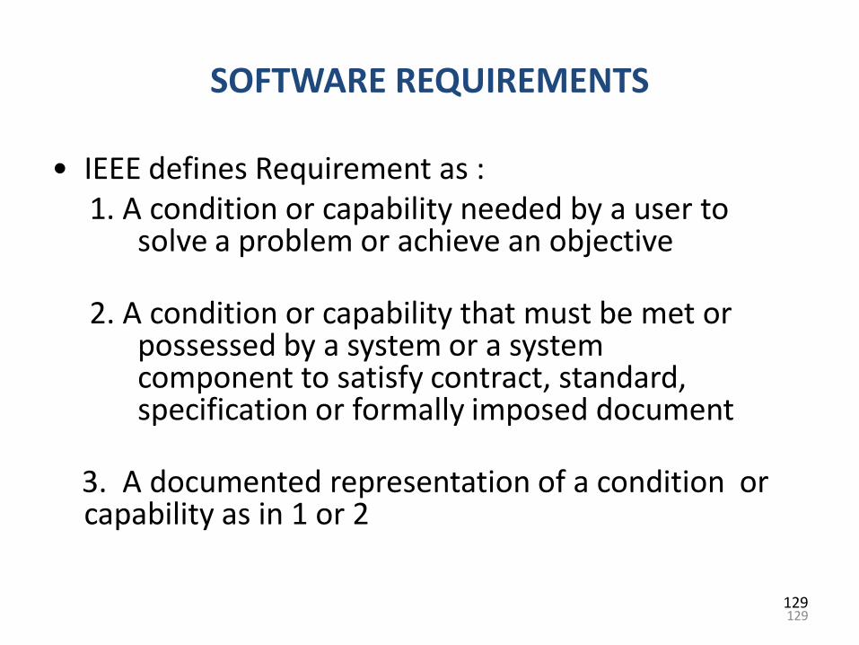
129
SOFTWARE REQUIREMENTS
• IEEE defines Requirement as :1. A condition or capability needed by a user to
solve a problem or achieve an objective
2. A condition or capability that must be met or possessed by a system or a system component to satisfy contract, standard, specification or formally imposed document
3. A documented representation of a condition or capability as in 1 or 2
129
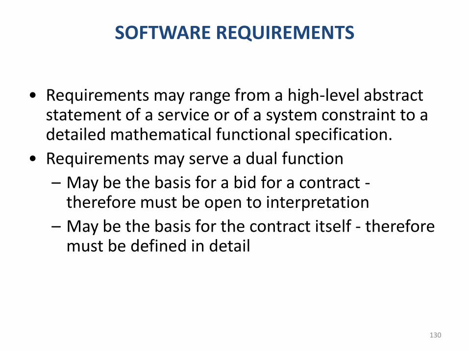
130
SOFTWARE REQUIREMENTS
• Requirements may range from a high-level abstract statement of a service or of a system constraint to a detailed mathematical functional specification.
• Requirements may serve a dual function
– May be the basis for a bid for a contract -therefore must be open to interpretation
– May be the basis for the contract itself - therefore must be defined in detail
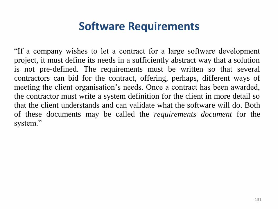
131
Software Requirements
“If a company wishes to let a contract for a large software development project, it must define its needs in a sufficiently abstract way that a solution is not pre-defined. The requirements must be written so that several contractors can bid for the contract, offering, perhaps, different ways of meeting the client organisation‟s needs. Once a contract has been awarded, the contractor must write a system definition for the client in more detail so that the client understands and can validate what the software will do. Both of these documents may be called the requirements document for the system.”
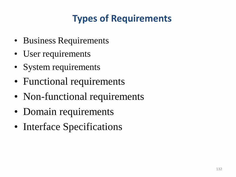
132
Types of Requirements
• Business Requirements
• User requirements
• System requirements
• Functional requirements
• Non-functional requirements
• Domain requirements
• Interface Specifications
Business Requirements
• A high-level business objective of the organization
that builds a product or of a customer who procures it
• Generally stated by the business owner or sponsor of
the project
– Example: A system is needed to track the
attendance of employees
– A system is needed to account the inventory of the
organization
133
Business RequirementsContents of Business Requirements:
• Purpose, Inscope, Out of Scope, Targeted Audiences
• Use Case diagrams
• Data Requirements
• Non Functional Requirements
• Interface Requirements
• Limitations
• Risks
• Assumptions
• Reporting Requirements
• Checklists
134
User Requirements
• A user requirement refers to a function that the userrequires a system to perform.
• Made through statements in natural language anddiagrams of the services the system provides and itsoperational constraints. Written for customers.
• User requirements are set by client and confirmedbefore system development.
– For example, in a system for a bank the user may require afunction to calculate interest over a set time period.
135
System Requirements
• A system requirement is a more technical requirement, often relating to hardware or software required for a system to function.
– System requirements may be something like - "The system must run on a server with IIS
– System requirements may also include validation requirements such as "File upload is limited to .xls format
• System requirements are more commonly used by developers throughout the development life cycle. The client will usually have less interest in these lower level requirements.
• A structured document setting out detailed descriptions of the system‟s functions, services and operational constraints.
136
Functional Requirements
• Statements of services the system should provide, how the system shouldreact to particular inputs and how the system should behave in particularsituations.
• A functional requirement defines a function of a software system or itscomponent.
• A function is described as a set of inputs, the behavior, and outputs.
• Functional requirements may be calculations, technical details, datamanipulation and processing and other specific functionality that define whata system is supposed to accomplish.
• Behavioral requirements describing all the cases where the system uses thefunctional requirements are captured in use cases
• Functional requirements drive the application architecture of a system
• The plan for implementing functional requirements is detailed in the systemdesign
137
Non-Functional Requirements
• A non-functional requirement is a requirement that specifies criteria that canbe used to judge the operation of a system, rather than specific behaviors
• The plan for implementing non-functional requirements is detailed in thesystem architecture.
• Non-functional requirements are often called qualities of a system. Otherterms for non-functional requirements are "constraints", "quality attributes","quality goals", "quality of service requirements" and "non-behavioralrequirements
• These define system properties and constraints e.g. reliability, response timeand storage requirements. Constraints are I/O device capability, systemrepresentations, etc.
• Process requirements may also be specified mandating a particular CASEsystem, programming language or development method.
• Non-functional requirements may be more critical than functionalrequirements. If these are not met, the system may become useless.
138
139
Non-Functional Requirements
• These define system properties and constraints e.g. reliability,response time and storage requirements. Constraints are I/Odevice capability, system representations, etc.
• Process requirements may also be specified mandating aparticular CASE system, programming language ordevelopment method.
• Non-functional requirements may be more critical thanfunctional requirements. If these are not met, the system isuseless.
140
Non-functional Requirements classifications
• Product requirements
– Requirements which specify that the delivered product must behave in
a particular way e.g. execution speed, reliability, etc.
• Organisational requirements
– Requirements which are a consequence of organisational policies and
procedures e.g. process standards used, implementation requirements,
etc.
• External requirements
– Requirements which arise from factors which are external to the system
and its development process e.g. interoperability requirements,
legislative requirements, etc.
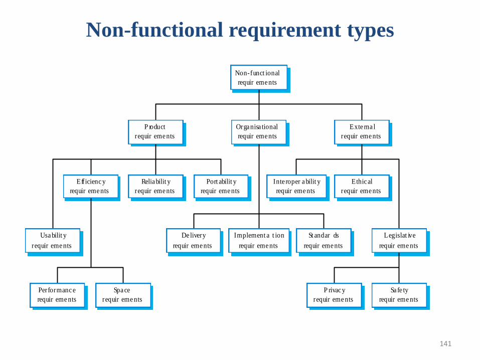
141
Non-functional requirement types
Performance
requir ements
Space
requir ements
Usa bilit y
requir ements
Efficiency
requir ements
Reliabilit y
requir ements
Port abilit y
requir ements
Inte roper a bilit y
requir ements
Ethical
requir ements
Legislat ive
requir ements
Implement a t ion
requir ements
St andar ds
requir ements
De livery
requir ements
Sa fe ty
requir ements
P rivacy
requir ements
P roduct
requir ements
Organisa tional
requir ements
Exte rna l
requir ements
Non-funct ional
requir ements
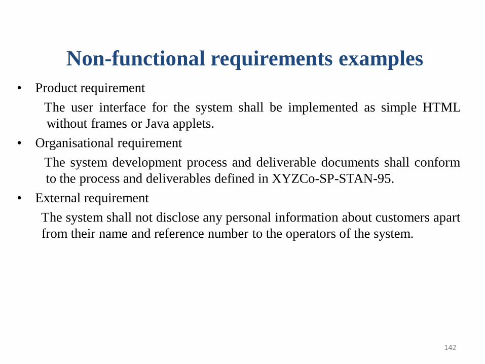
142
Non-functional requirements examples
• Product requirement
The user interface for the system shall be implemented as simple HTML
without frames or Java applets.
• Organisational requirement
The system development process and deliverable documents shall conform
to the process and deliverables defined in XYZCo-SP-STAN-95.
• External requirement
The system shall not disclose any personal information about customers apart
from their name and reference number to the operators of the system.
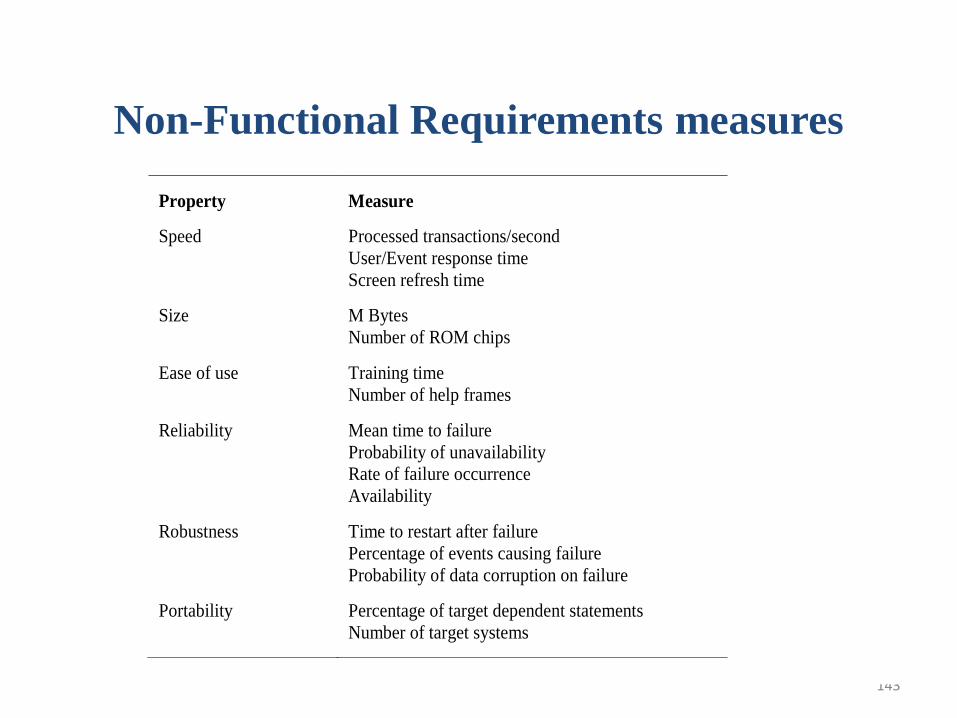
143
Non-Functional Requirements measures
Property Measure
Speed Processed transactions/second
User/Event response time
Screen refresh time
Size M Bytes
Number of ROM chips
Ease of use Training time
Number of help frames
Reliability Mean time to failure
Probability of unavailability
Rate of failure occurrence
Availability
Robustness Time to restart after failure
Percentage of events causing failure
Probability of data corruption on failure
Portability Percentage of target dependent statements
Number of target systems
Domain Requirements
• Domain requirements reflect the environment in which the system operatesso, when we talk about an application domain it means environments suchas train operation, medical records, e-commerce etc.
• Domain requirements may be expressed using specialized domainterminology or reference to domain concepts. Because these requirementsare specialized, software engineers often find it difficult to understand howthey are related to other system requirements
• Domain requirements are important because they often reflect fundamentalsof the application domain. If these requirements are not satisfied, it may beimpossible to make the system work satisfactorily.
• For example, the requirements for an insulin pump system that deliversinsulin on demand include the following domain requirement:
– The system safety shall be assured according to standard IEC 60601-1:MedicalElectrical Equipment – Part 1:General Requirements for Basic Safety andEssential Performance
144
145
Domain requirements problems
• Understandability
– Requirements are expressed in the language of the
application domain
– This is often not understood by software engineers
developing the system.
• Implicitness
– Domain specialists understand the area so well that they do
not think of making the domain requirements explicit.
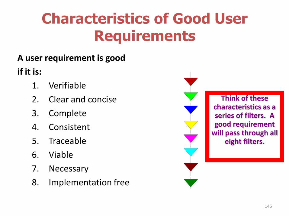
Characteristics of Good User Requirements
A user requirement is good
if it is:
1. Verifiable
2. Clear and concise
3. Complete
4. Consistent
5. Traceable
6. Viable
7. Necessary
8. Implementation free
146
Think of these characteristics as a series of filters. A good requirement
will pass through all eight filters.
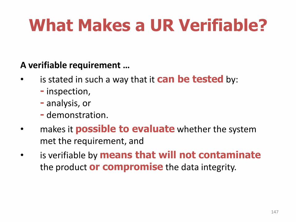
What Makes a UR Verifiable?
A verifiable requirement …
• is stated in such a way that it can be tested by:- inspection, - analysis, or - demonstration.
• makes it possible to evaluate whether the system met the requirement, and
• is verifiable by means that will not contaminatethe product or compromise the data integrity.
147
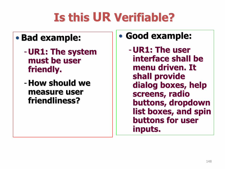
Is this UR Verifiable?
148
• Good example:
-UR1: The user interface shall be menu driven. It shall provide dialog boxes, help screens, radio buttons, dropdown list boxes, and spin buttons for user inputs.
• Bad example:
-UR1: The system must be user friendly.
-How should we measure user friendliness?
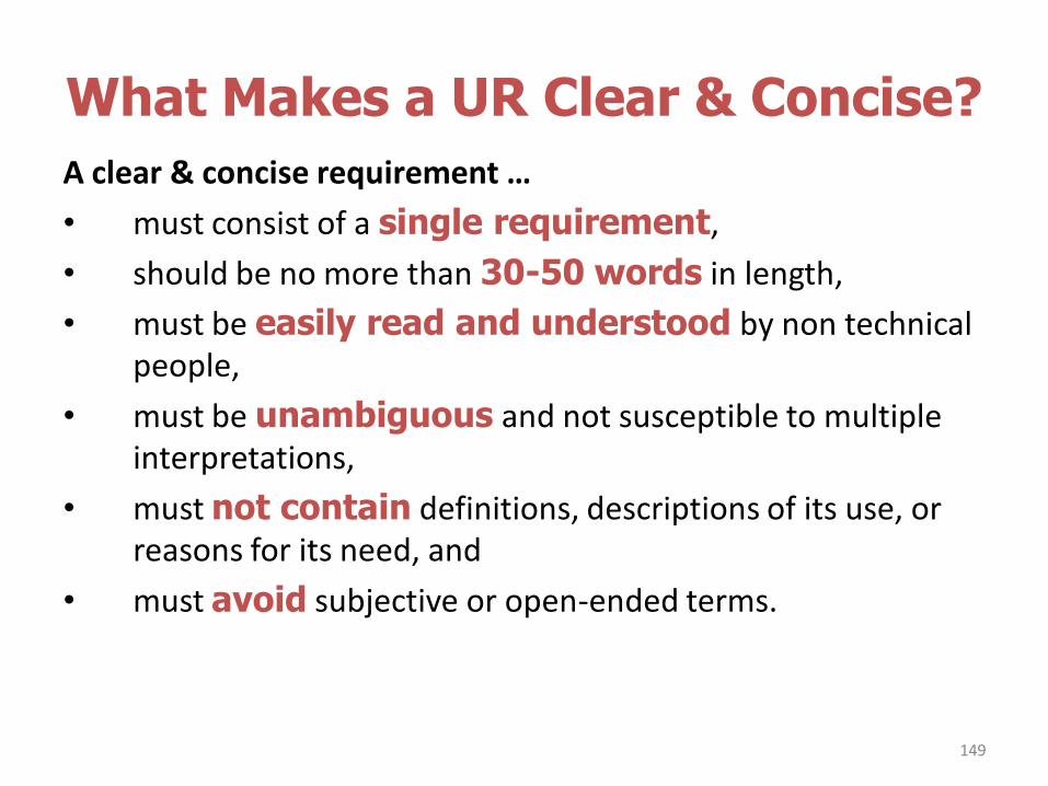
What Makes a UR Clear & Concise?
A clear & concise requirement …
• must consist of a single requirement,
• should be no more than 30-50 words in length,
• must be easily read and understood by non technical people,
• must be unambiguous and not susceptible to multiple interpretations,
• must not contain definitions, descriptions of its use, or reasons for its need, and
• must avoid subjective or open-ended terms.
149
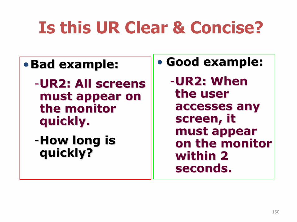
Is this UR Clear & Concise?
150
• Good example:
-UR2: When the user accesses any screen, it must appear on the monitor within 2 seconds.
•Bad example:
-UR2: All screens must appear on the monitor quickly.
-How long is quickly?
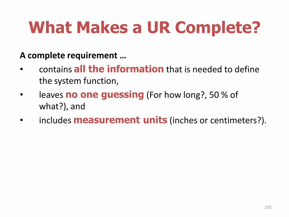
What Makes a UR Complete?
A complete requirement …
• contains all the information that is needed to define the system function,
• leaves no one guessing (For how long?, 50 % of what?), and
• includes measurement units (inches or centimeters?).
151
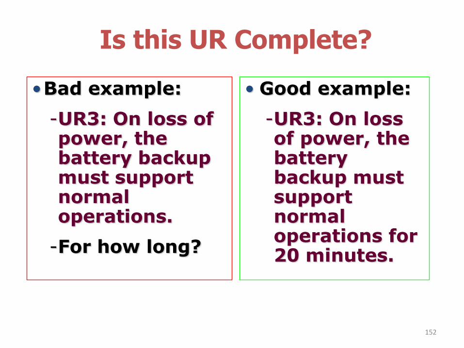
Is this UR Complete?
152
• Good example:
-UR3: On loss of power, the battery backup must support normal operations for 20 minutes.
•Bad example:
-UR3: On loss of power, the battery backup must support normal operations.
-For how long?
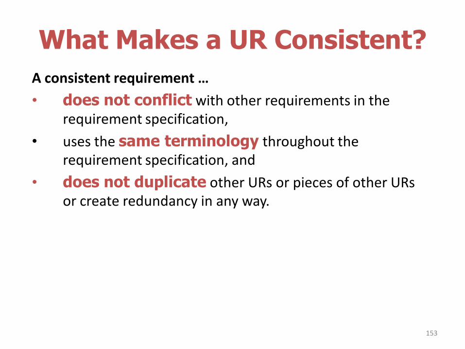
What Makes a UR Consistent?
A consistent requirement …
• does not conflict with other requirements in the requirement specification,
• uses the same terminology throughout the requirement specification, and
• does not duplicate other URs or pieces of other URs or create redundancy in any way.
153
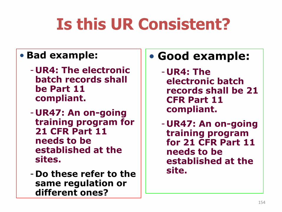
Is this UR Consistent?
154
• Good example:
-UR4: The electronic batch records shall be 21 CFR Part 11 compliant.
-UR47: An on-going training program for 21 CFR Part 11 needs to be established at the site.
• Bad example:
-UR4: The electronic batch records shall be Part 11 compliant.
-UR47: An on-going training program for 21 CFR Part 11 needs to be established at the sites.
-Do these refer to the same regulation or different ones?
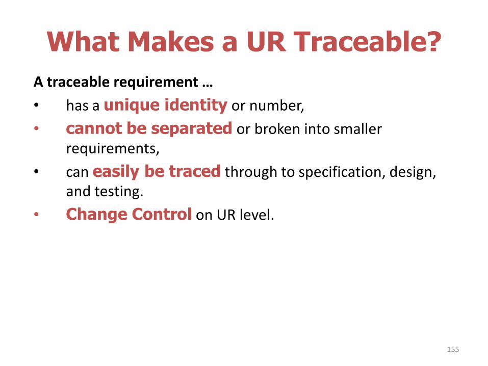
What Makes a UR Traceable?
A traceable requirement …
• has a unique identity or number,
• cannot be separated or broken into smaller requirements,
• can easily be traced through to specification, design, and testing.
• Change Control on UR level.
155
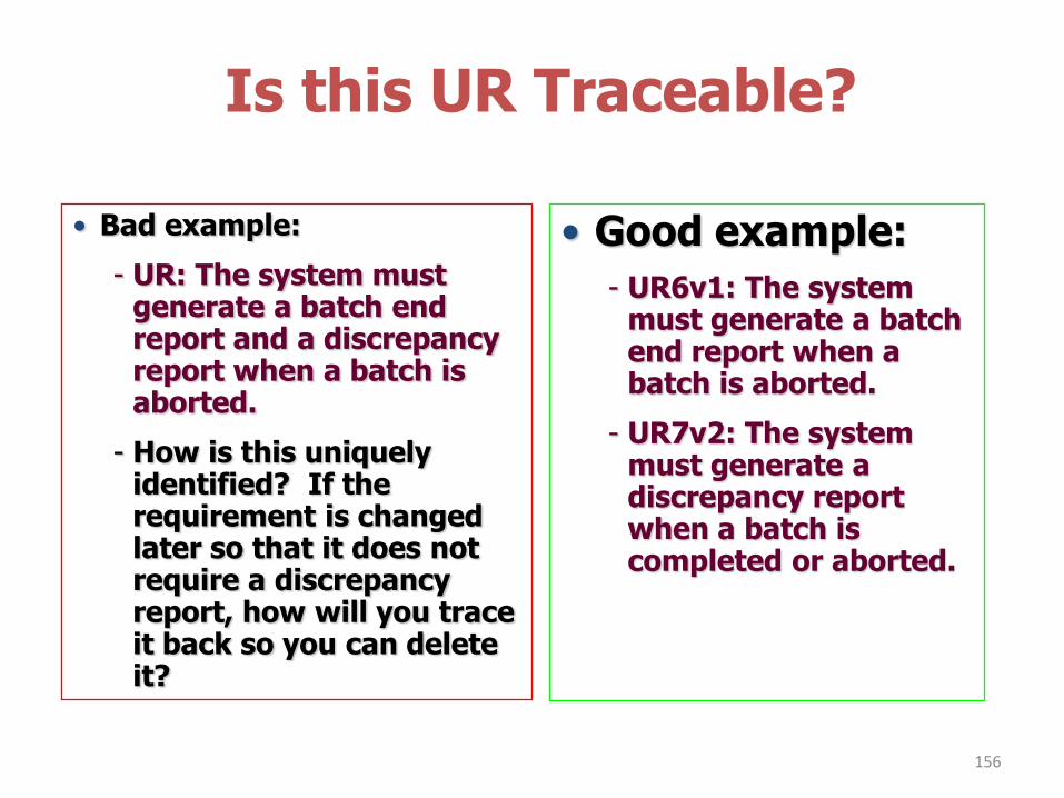
Is this UR Traceable?
156
• Good example:
- UR6v1: The system must generate a batch end report when a batch is aborted.
- UR7v2: The system must generate a discrepancy report when a batch is completed or aborted.
• Bad example:
- UR: The system must generate a batch end report and a discrepancy report when a batch is aborted.
- How is this uniquely identified? If the requirement is changed later so that it does not require a discrepancy report, how will you trace it back so you can delete it?
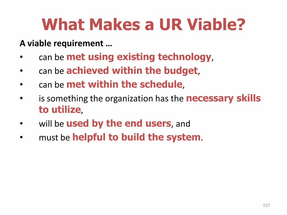
What Makes a UR Viable?A viable requirement …
• can be met using existing technology,
• can be achieved within the budget,
• can be met within the schedule,
• is something the organization has the necessary skills to utilize,
• will be used by the end users, and
• must be helpful to build the system.
157
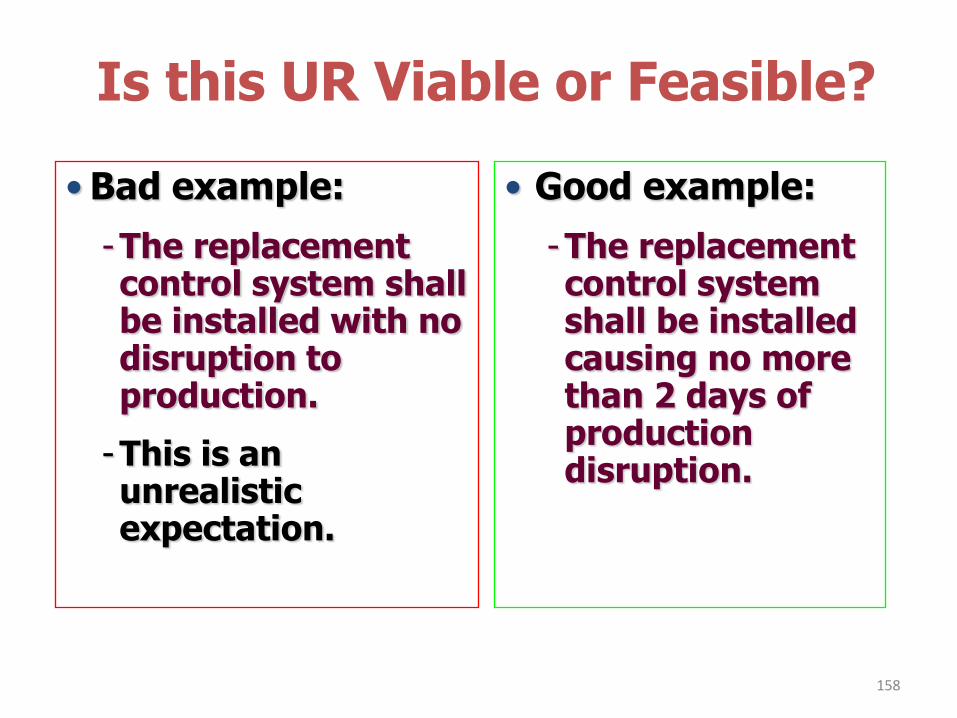
Is this UR Viable or Feasible?
158
• Good example:
-The replacement control system shall be installed causing no more than 2 days of production disruption.
• Bad example:
-The replacement control system shall be installed with no disruption to production.
-This is an unrealistic expectation.
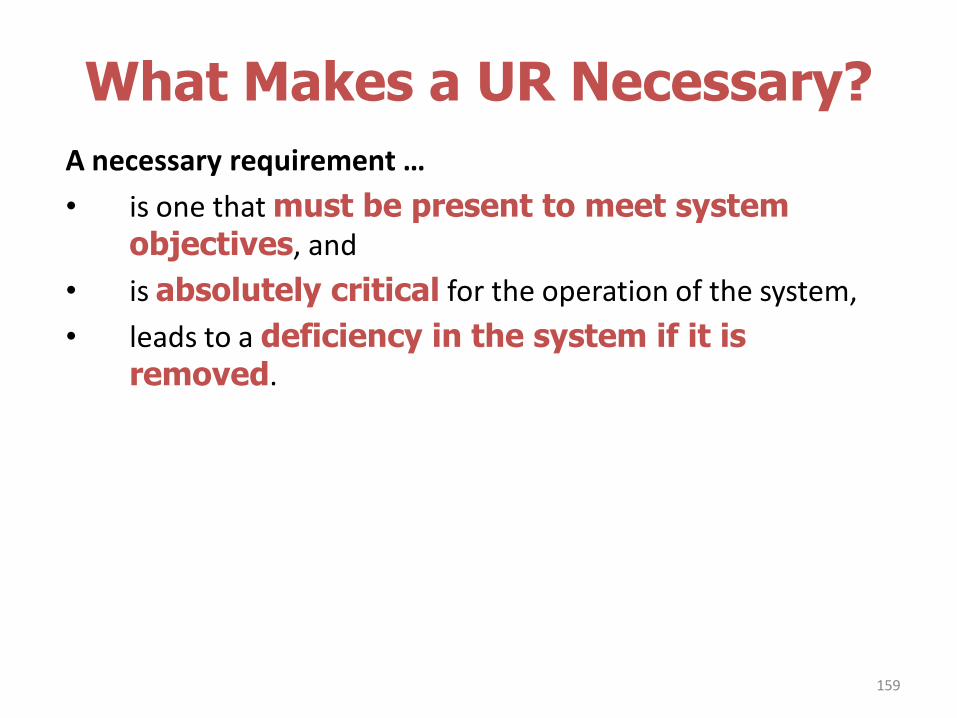
What Makes a UR Necessary?
A necessary requirement …
• is one that must be present to meet system objectives, and
• is absolutely critical for the operation of the system,
• leads to a deficiency in the system if it is removed.
159
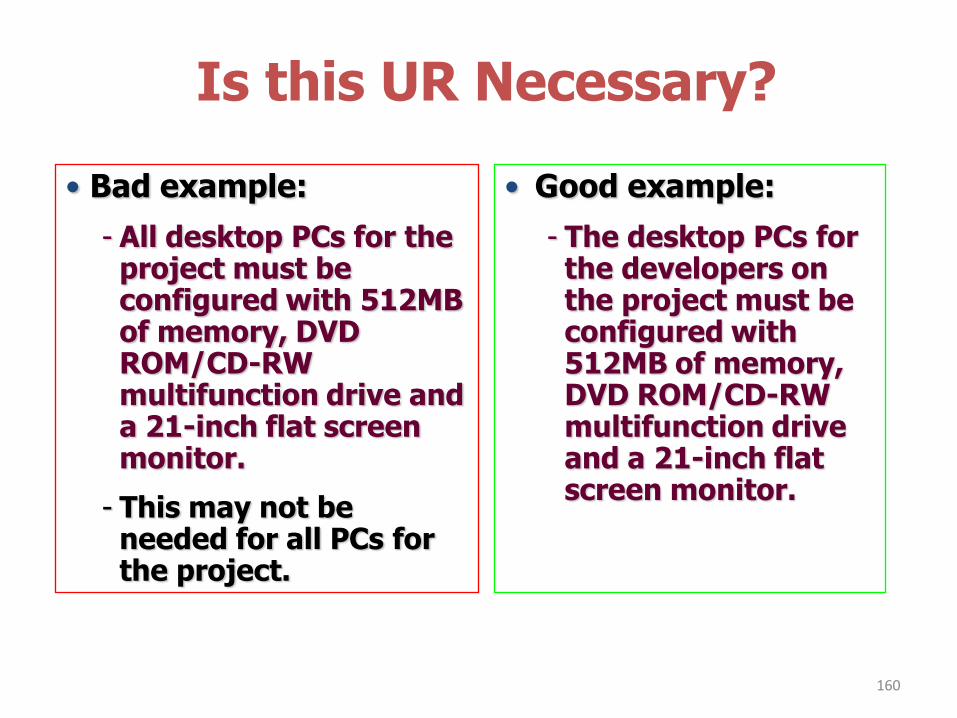
Is this UR Necessary?
160
• Good example:
- The desktop PCs for the developers on the project must be configured with 512MB of memory, DVD ROM/CD-RW multifunction drive and a 21-inch flat screen monitor.
• Bad example:
- All desktop PCs for the project must be configured with 512MB of memory, DVD ROM/CD-RW multifunction drive and a 21-inch flat screen monitor.
- This may not be needed for all PCs for the project.
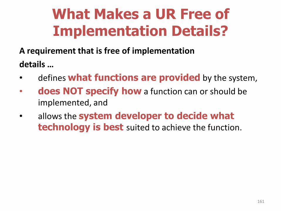
What Makes a UR Free of Implementation Details?
A requirement that is free of implementation
details …
• defines what functions are provided by the system,
• does NOT specify how a function can or should be implemented, and
• allows the system developer to decide what technology is best suited to achieve the function.
161
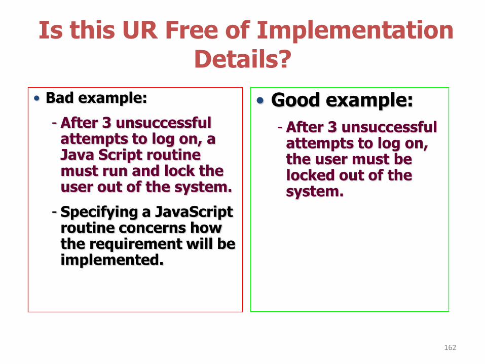
Is this UR Free of Implementation Details?
162
• Good example:
- After 3 unsuccessful attempts to log on, the user must be locked out of the system.
• Bad example:
- After 3 unsuccessful attempts to log on, a Java Script routine must run and lock the user out of the system.
- Specifying a JavaScript routine concerns how the requirement will be implemented.
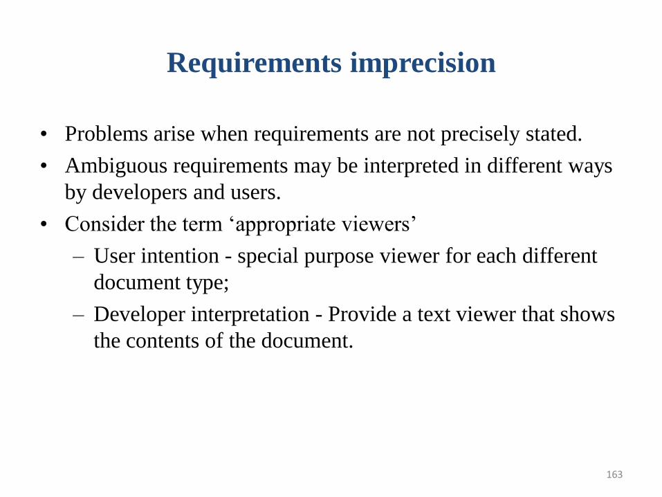
163
Requirements imprecision
• Problems arise when requirements are not precisely stated.
• Ambiguous requirements may be interpreted in different ways
by developers and users.
• Consider the term „appropriate viewers‟
– User intention - special purpose viewer for each different
document type;
– Developer interpretation - Provide a text viewer that shows
the contents of the document.
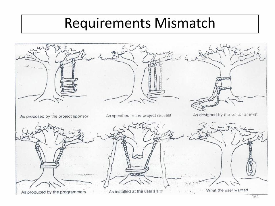
164164
Requirements Mismatch
165
Interface specification
• Most systems must operate with other systems and the operating interfaces must be specified as part of the requirements.
• Three types of interface may have to be defined
– Procedural interfaces;
– Data structures that are exchanged;
– Data representations.
• Formal notations are an effective technique for interface
specification.
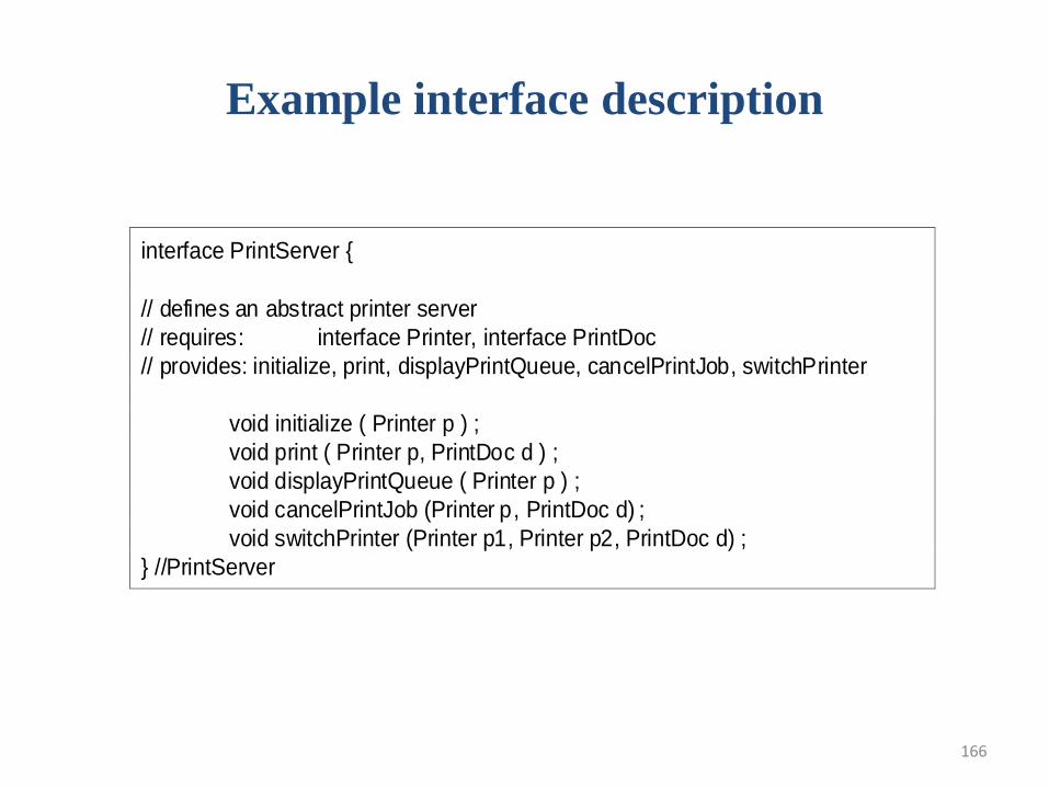
166
Example interface description
interface PrintServer {
// defines an abstract printer server
// requires: interface Printer, interface PrintDoc
// provides: initialize, print, displayPrintQueue, cancelPrintJob, switchPrinter
void initialize ( Printer p ) ;
void print ( Printer p, PrintDoc d ) ;
void displayPrintQueue ( Printer p ) ;
void cancelPrintJob (Printer p, PrintDoc d) ;
void switchPrinter (Printer p1, Printer p2, PrintDoc d) ;
} //PrintServer
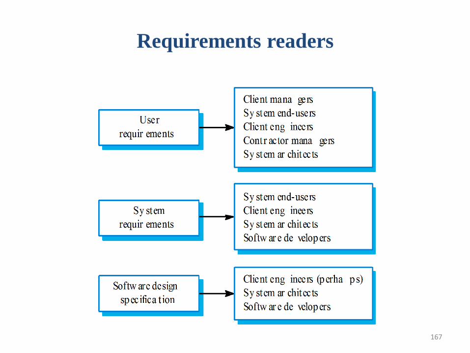
167
Requirements readers
168
Requirements and design
• In principle, requirements should state what the system should do and the design should describe how it does this.
• In practice, requirements and design are inseparable
– A system architecture may be designed to structure the requirements;
– The system may inter-operate with other systems that generate design requirements;
– The use of a specific design may be a domain requirement.
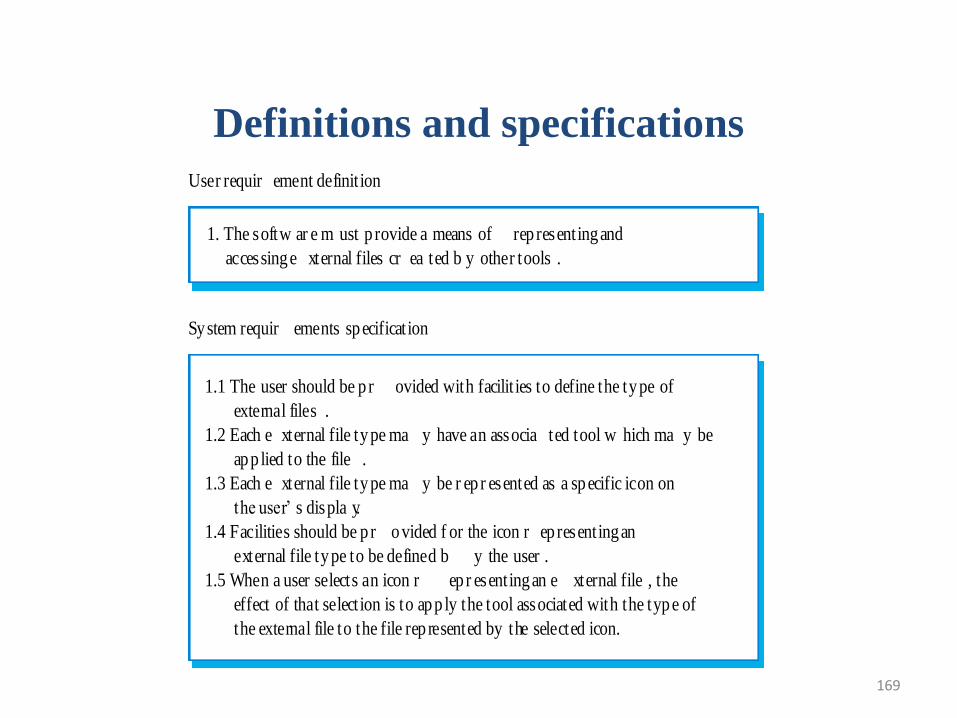
169
Definitions and specifications
1. The softw ar e m ust p rovide a means of rep resenting and
1. accessing e xternal files cr ea ted b y other tools .
1.1 The user should be p r ovided with facilit ies to define the type of
1.2 external files .
1.2 Each e xternal file type ma y have an associa ted tool w hich ma y be
1.2 app lied to the file .
1.3 Each e xternal file type ma y be r ep r esented as a specific icon on
1.2 the user‟ s displa y.
1.4 Facilities should be p r ovided f or the icon r ep resenting an
1.2 external file type to be defined b y the user .
1.5 When a user selects an icon r ep r esenting an e xternal file , the
1.2 effect of that selection is to app ly the tool associated with the type of
1.2 the external file to the file rep resented by the selected icon.
User requir ement definit ion
System requir ements specification
170
Specifying User requirements
• Should describe functional and non-functional requirements in
such a way that they are understandable by system users who
don‟t have detailed technical knowledge.
• User requirements are defined using natural language, tables
and diagrams as these can be understood by all users.
171
Problems with natural language
• Lack of clarity
– Precision is difficult without making the document
difficult to read.
• Requirements confusion
– Functional and non-functional requirements tend
to be mixed-up.
• Requirements amalgamation
– Several different requirements may be expressed
together.
172
Problems with NL specification
• Ambiguity
– The readers and writers of the requirement must interpret the same words in the same way. NL is naturally ambiguous so this is very difficult.
• Over-flexibility
– The same thing may be said in a number of different ways in the specification.
• Lack of modularisation
– NL structures are inadequate to structure system requirements.
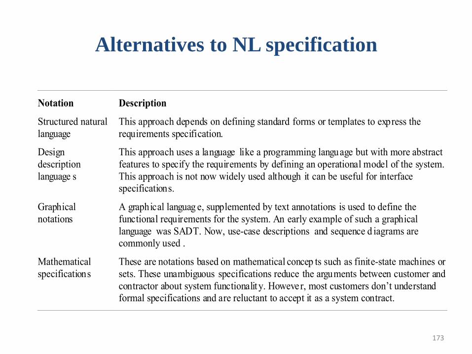
173
Alternatives to NL specification
Notation Description
Structured natural
language
This approach depends on defining standard forms or templates to express the
requirements specification.
Design
description
language s
This approach uses a language like a programming language but with more abstract
features to specify the requirements by defining an operational model of the system.
This approach is not now widely used although it can be useful for interfacespecifications.
Graphical
notations
A graphical languag e, supplemented by text annotations is used to define the
functional requirements for the system. An early example of such a graphical
language was SADT. Now, use-case descriptions and sequence d iagrams arecommonly used .
Mathematical
specifications
These are notations based on mathematical concep ts such as finite-state machines or
sets. These unambiguous specifications reduce the arguments between customer and
contractor about system functionalit y. However, most customers don’t understandformal specifications and are reluctant to accept it as a system contract.
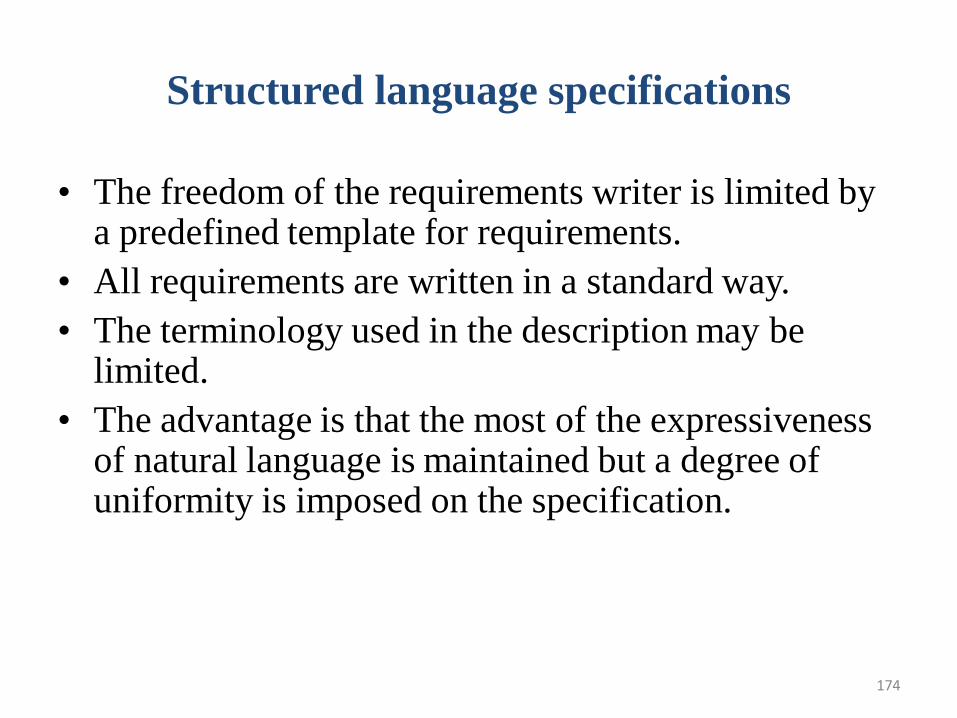
174
Structured language specifications
• The freedom of the requirements writer is limited by a predefined template for requirements.
• All requirements are written in a standard way.
• The terminology used in the description may be limited.
• The advantage is that the most of the expressiveness of natural language is maintained but a degree of uniformity is imposed on the specification.
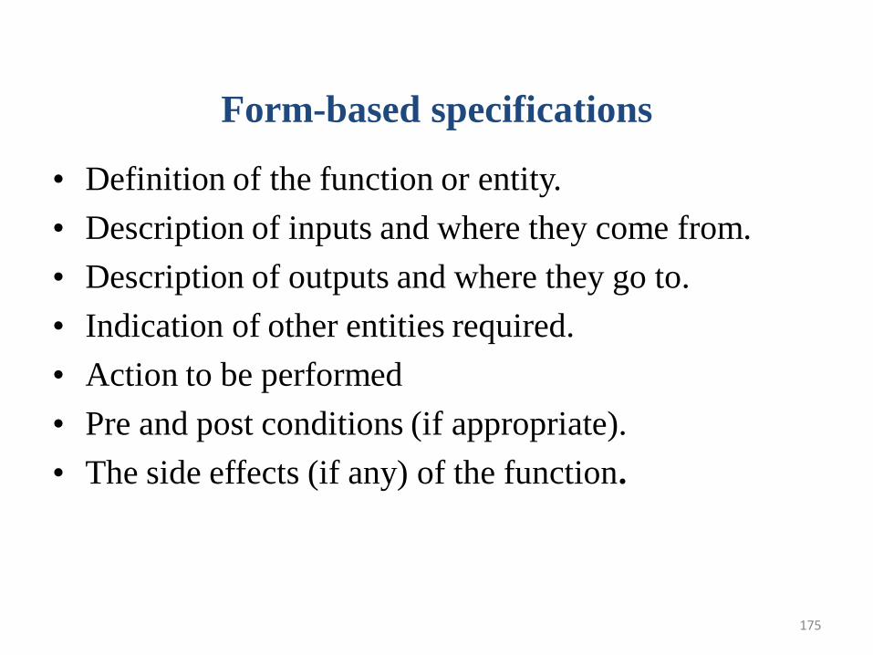
175
Form-based specifications
• Definition of the function or entity.
• Description of inputs and where they come from.
• Description of outputs and where they go to.
• Indication of other entities required.
• Action to be performed
• Pre and post conditions (if appropriate).
• The side effects (if any) of the function.
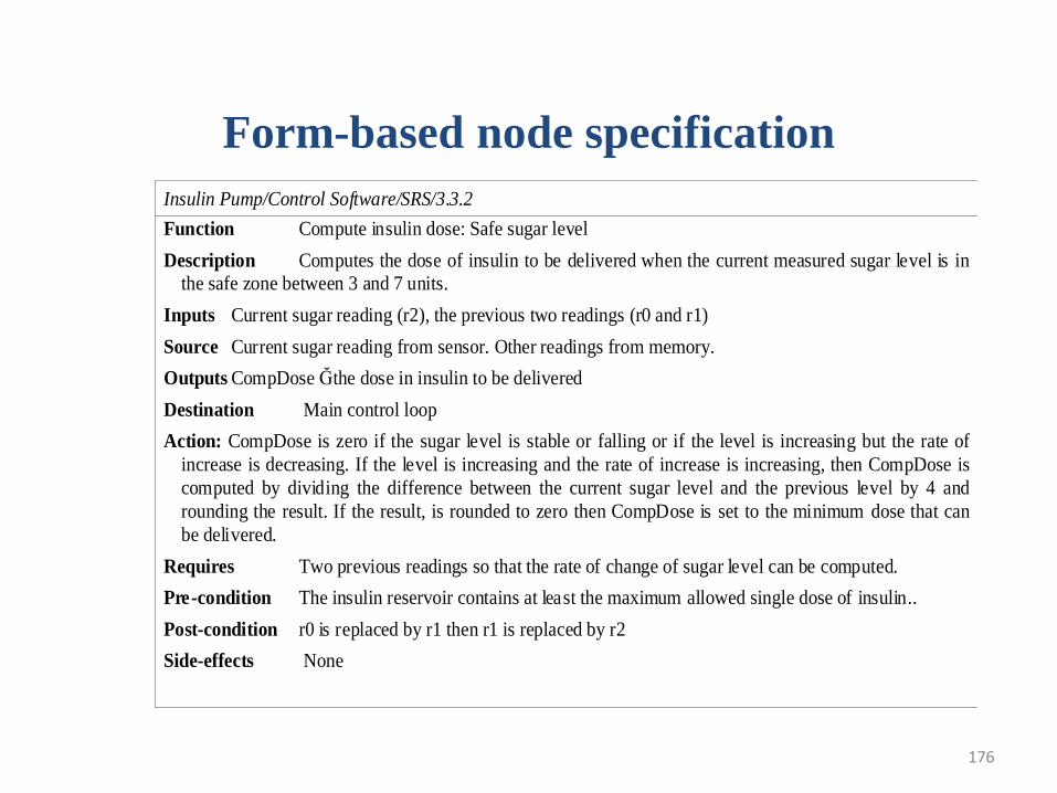
176
Form-based node specification
Insulin Pump/Control Software/SRS/3.3.2
Function Compute insulin dose: Safe sugar level
Description Computes the dose of insulin to be delivered when the current measured sugar level is in
the safe zone between 3 and 7 units.
Inputs Current sugar reading (r2), the previous two readings (r0 and r1)
Source Current sugar reading from sensor. Other readings from memory.
Outputs CompDose Ğ the dose in insulin to be delivered
Destination Main control loop
Action: CompDose is zero if the sugar level is stable or falling or if the level is increasing but the rate of
increase is decreasing. If the level is increasing and the rate of increase is increasing, then CompDose is
computed by dividing the difference between the current sugar level and the previous level by 4 and
rounding the result. If the result, is rounded to zero then CompDose is set to the minimum dose that can
be delivered.
Requires Two previous readings so that the rate of change of sugar level can be computed.
Pre-condition The insulin reservoir contains at least the maximum allowed single dose of insulin..
Post-condition r0 is replaced by r1 then r1 is replaced by r2
Side-effects None
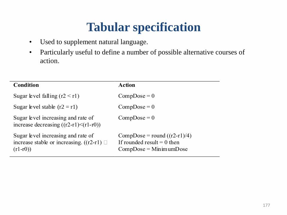
177
Tabular specification
Condition Action
Sugar level falling (r2 < r1) CompDose = 0
Sugar level stable (r2 = r1) CompDose = 0
Sugar level increasing and rate of
increase decreasing ((r2-r1)<(r1-r0))
CompDose = 0
Sugar level increasing and rate of
increase stable or increasing. ((r2-r1) •
(r1-r0))
CompDose = round ((r2-r1)/4)
If rounded result = 0 then
CompDose = MinimumDose
• Used to supplement natural language.
• Particularly useful to define a number of possible alternative courses of
action.
178
Graphical models
• Graphical models are most useful when you
need to show how state changes or where there
is a need to describe a sequence of actions.
179
Sequence diagrams
• These show the sequence of events that take place during some user interaction with a system.
• You read them from top to bottom to see the order of the actions that take place.
• Cash withdrawal from an ATM
– Validate card;
– Handle request;
– Complete transaction.
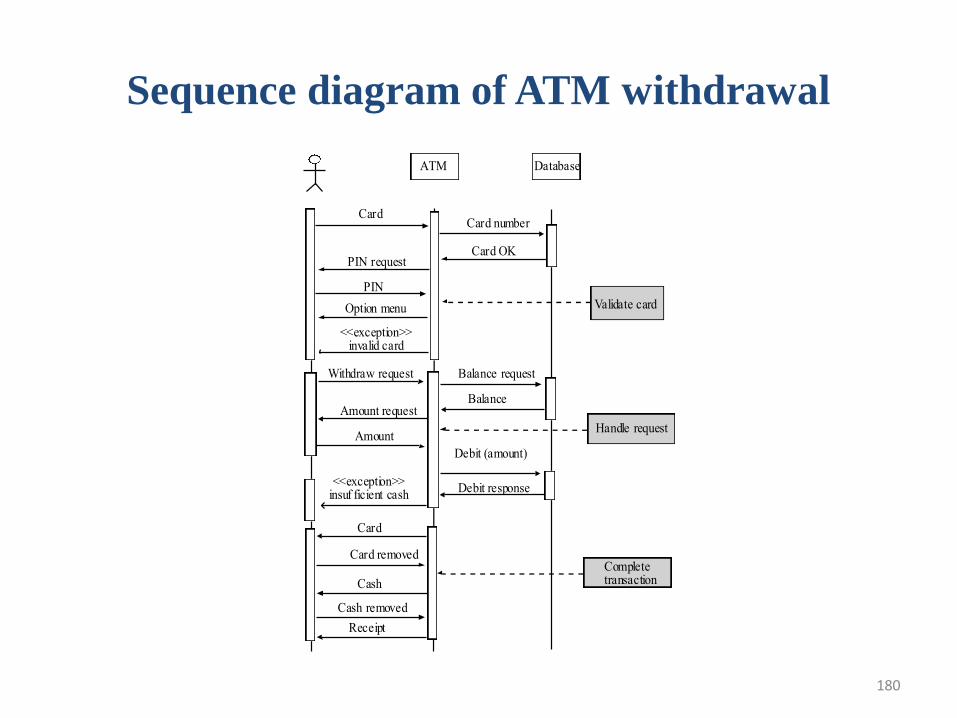
180
Sequence diagram of ATM withdrawal
ATM Database
CardCard number
Card OKPIN request
PIN
Option menu
<<exception>>invalid card
Withdraw request
Amount request
Amount
Balance request
Balance
<<exception>>insuf ficient cash
Debit (amount)
Debit response
Card
Card removed
Cash
Cash removed
Receipt
Validate card
Handle request
Completetransaction
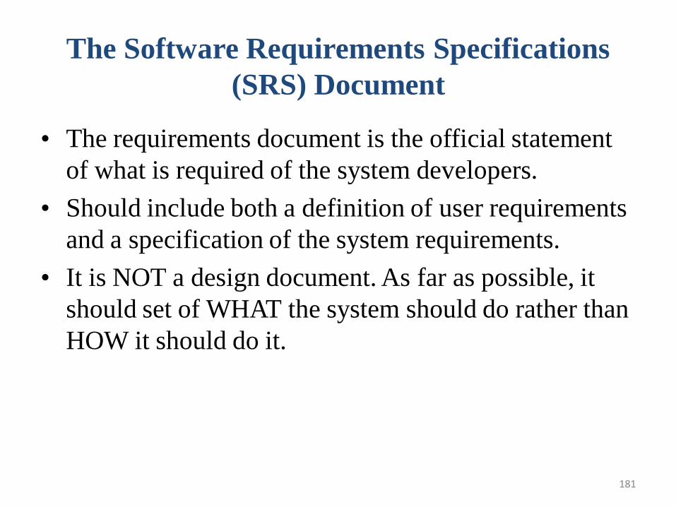
181
The Software Requirements Specifications
(SRS) Document
• The requirements document is the official statement
of what is required of the system developers.
• Should include both a definition of user requirements
and a specification of the system requirements.
• It is NOT a design document. As far as possible, it
should set of WHAT the system should do rather than
HOW it should do it.
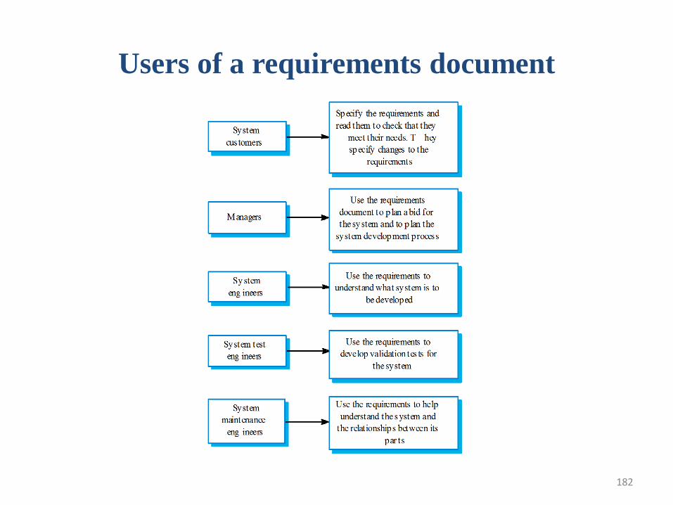
182
Users of a requirements document
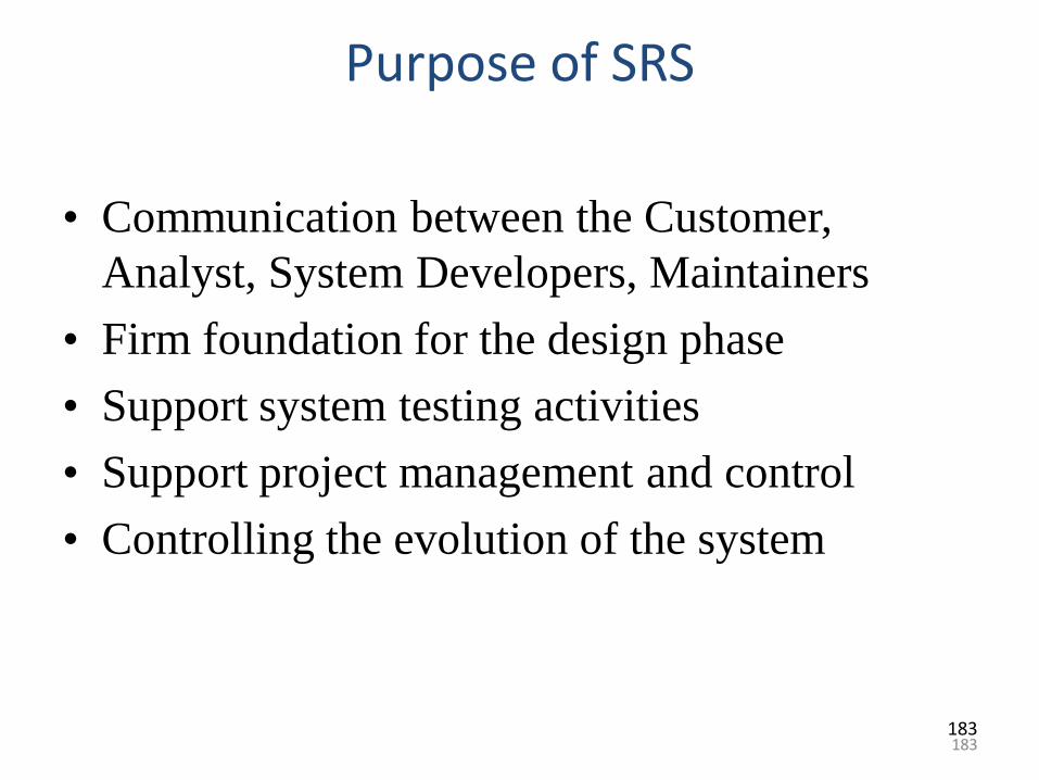
183
Purpose of SRS
• Communication between the Customer,
Analyst, System Developers, Maintainers
• Firm foundation for the design phase
• Support system testing activities
• Support project management and control
• Controlling the evolution of the system
183
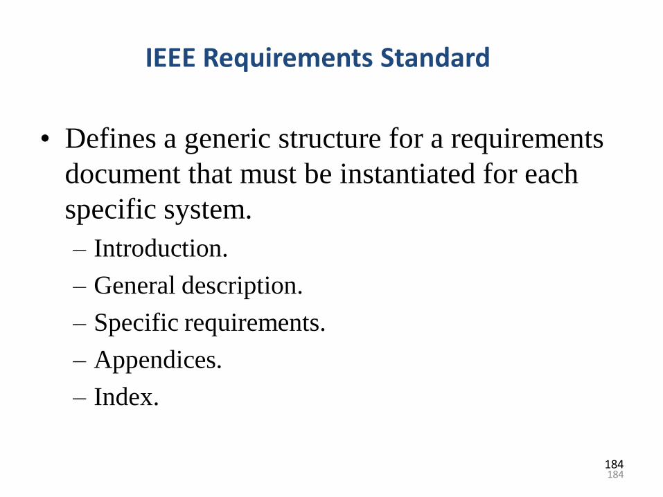
184
IEEE Requirements Standard
• Defines a generic structure for a requirements
document that must be instantiated for each
specific system.
– Introduction.
– General description.
– Specific requirements.
– Appendices.
– Index.
184
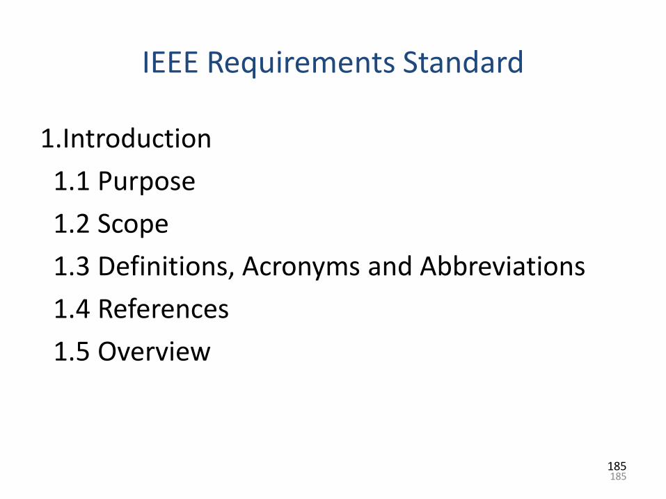
185
IEEE Requirements Standard
1.Introduction
1.1 Purpose
1.2 Scope
1.3 Definitions, Acronyms and Abbreviations
1.4 References
1.5 Overview
185
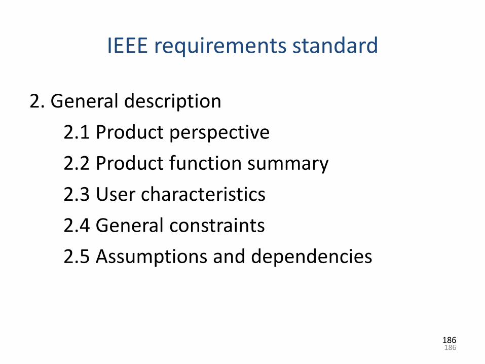
186
IEEE requirements standard
2. General description
2.1 Product perspective
2.2 Product function summary
2.3 User characteristics
2.4 General constraints
2.5 Assumptions and dependencies
186
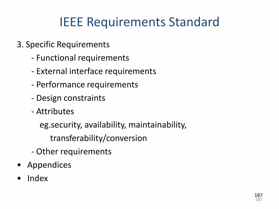
187
IEEE Requirements Standard
3. Specific Requirements
- Functional requirements
- External interface requirements
- Performance requirements
- Design constraints
- Attributes
eg.security, availability, maintainability,
transferability/conversion
- Other requirements
• Appendices
• Index
187
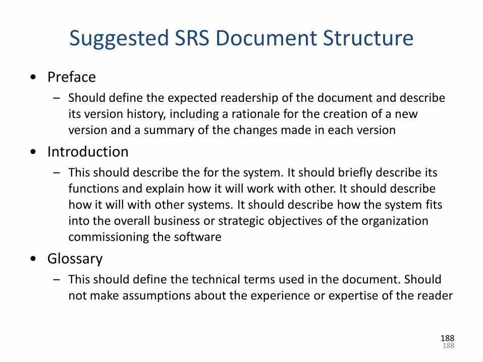
188
Suggested SRS Document Structure
• Preface– Should define the expected readership of the document and describe
its version history, including a rationale for the creation of a new version and a summary of the changes made in each version
• Introduction– This should describe the for the system. It should briefly describe its
functions and explain how it will work with other. It should describe how it will with other systems. It should describe how the system fits into the overall business or strategic objectives of the organization commissioning the software
• Glossary– This should define the technical terms used in the document. Should
not make assumptions about the experience or expertise of the reader
188
189
Suggested SRS Document Structure
• User Requirements Definition– The services provided for the user and the non-functional system
requirements should be described in this section. This description may use natural language, diagrams or other notations that are understandable by customers. Product and process standards which must be followed should be specified
• System Architecture– This chapter should present a high-level overview of the anticipated
system architecture showing the distribution of functions across modules. Architectural components that re reused should be highlighted
• System Requirements Specification– This should describe the functional and non-functional requirements
in more detail. If necessary, further detail may also be added to the non-functional requirements e.g. interfaces to other systems may be defined
189
190
Suggested SRS Document Structure
• System Models– This should set out one or more system models showing the
relationships between the system components and the system and its environment. These might be object models and data-flow models
• System Evolution– This should describe the fundamental assumptions on which the
system is based and anticipated changes due to hardware evolution, changing user needs etc
• Appendices– These should provide detailed, specific information which is related to
the application which is being developed. E.g. Appendices that may include hardware and database descriptions.
• Index– Several indexes to the document may be included
190
191
Requirements Engineering Processes
• A customer says “ I know you think you understand what I said, but what you don‟t understand is what I said is not what I mean”
• Requirement engineering helps software engineers to better understand the problem to solve.
• It is carried out by software engineers (analysts) and other project stakeholders
• It is important to understand what the customer wants before one begins to design and build a computer based system
• Work products include user scenarios, functions and feature lists, analysis models
Requirements Engineering Processes
• Requirements engineering (RE) is a systems and software engineering process which covers all of the activities involved in discovering, documenting and maintaining a set of requirements for a computer-based system
• The processes used for RE vary widely depending on the application domain, the people involved and the organisation developing the requirements.
• Activities within the RE process may include:
– Requirements elicitation - discovering requirements from system stakeholders
– Requirements Analysis and negotiation - checking requirements and resolving stakeholder conflicts
192
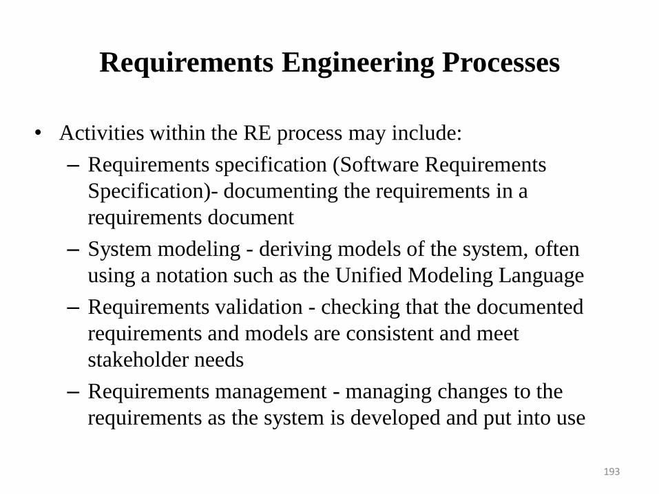
Requirements Engineering Processes
• Activities within the RE process may include:
– Requirements specification (Software Requirements
Specification)- documenting the requirements in a
requirements document
– System modeling - deriving models of the system, often
using a notation such as the Unified Modeling Language
– Requirements validation - checking that the documented
requirements and models are consistent and meet
stakeholder needs
– Requirements management - managing changes to the
requirements as the system is developed and put into use
193
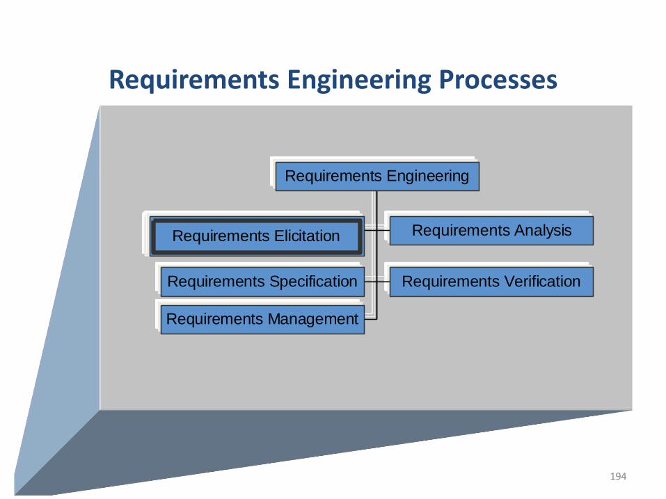
194
Requirements Engineering Processes
Requirements Elicitation Requirements Analysis
Requirements Specification Requirements Verification
Requirements Management
Requirements Engineering
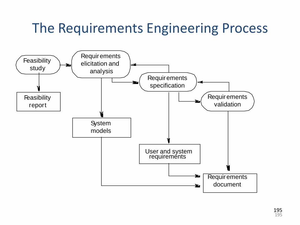
195
The Requirements Engineering Process
Feasibility
study
Requirements
elicitation and
analysisRequirements
specification
Requirements
validationFeasibility
report
System
models
User and systemrequirements
Requirements
document
195
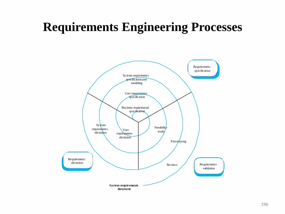
Requirements Engineering Processes
196
Requirements
specification
Requirements
validation
Requirementselicitation
System requirements
specification andmodeling
System
requirementselicitation
User requirementsspecification
Userrequirements
elicitation
Business requirementsspecification
Prototyping
Feasibility
study
Reviews
System requirements
document
Feasibility studies
• The purpose of feasibility study is not to solve the problem, but to determine whether the problem is worth solving.
• A feasibility study decides whether or not the proposed system is worthwhile.
• The feasibility study concentrates on the following area.
– Operational Feasibility
– Technical Feasibility
– Economic Feasibility
197
Feasibility studies
• A short focused study that checks
– If the system contributes to organisational
objectives;
– If the system can be engineered using current
technology and within budget;
– If the system can be integrated with other systems
that are used.
198
Feasibility study implementation
• Based on information assessment (what is required),
information collection and report writing.
• Questions for people in the organisation
– What if the system wasn‟t implemented?
– What are current process problems?
– How will the proposed system help?
– What will be the integration problems?
– Is new technology needed? What skills?
– What facilities must be supported by the proposed system?
199
Requirements Analysis
• Requirements analysis in systems engineering and software engineering, encompasses those tasks that go into determining the needs or conditions to meet for a new or altered product, taking account of the possibly conflicting requirements of the various stakeholders, such as beneficiaries or users.
• Requirements analysis is critical to the success of a systems or software project. The requirements should be documented, actionable, measurable, testable, traceable, related to identified business needs or opportunities, and defined to a level of detail sufficient for system design.
200
Requirement Analysis
• Requirements analysis includes three types of activities
– Eliciting requirements: The task of identifying the varioustypes of requirements from various sources includingproject documentation, (e.g. the project charter ordefinition), business process documentation, andstakeholder interviews. This is sometimes also calledrequirements gathering.
– Analyzing requirements: determining whether the statedrequirements are clear, complete, consistent andunambiguous, and resolving any apparent conflicts.
– Recording requirements: Requirements may bedocumented in various forms, usually including a summarylist and may include natural-language documents, usecases, user stories, or process specifications.
201
Problems of Requirements Analysis
• Stakeholders don‟t know what they really want.
• Stakeholders express requirements in their own terms.
• Different stakeholders may have conflicting requirements.
• Organisational and political factors may influence the system
requirements.
• The requirements change during the analysis process. New
stakeholders may emerge and the business environment
change.
202
Requirement Elicitation • Requirements elicitation is the practice of collecting the
requirements of a system from users, customers and otherstakeholders. Sometimes called Requirements Discovery
• Requirements elicitation is important because one can never besure to get all requirements from the user and customer by justasking them what the system should do
• Requirements elicitation practices include interviews,questionnaires, user observation, workshops, brain storming,use cases, role playing and prototyping.
• Before requirements can be analyzed, modeled, or specifiedthey must be gathered through an elicitation process.
• Requirements elicitation is a part of the requirementsengineering process, usually followed by analysis andspecification of the requirements.
203
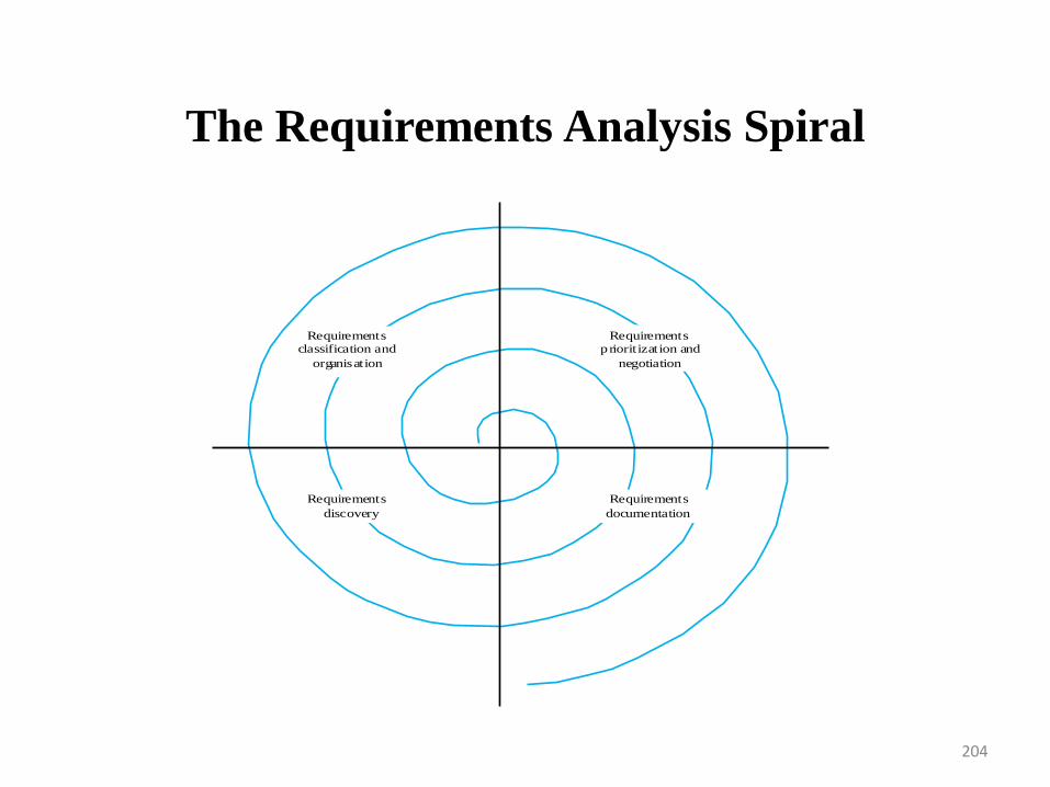
The Requirements Analysis Spiral
204
Requirementsclassification and
organisation
Requirementsprioritization and
negotiation
Requirements
documentation
Requirements
discovery
Requirements Analysis Process activities
• Requirements discovery
– Interacting with stakeholders to discover their requirements. Domain requirements are also discovered at this stage.
• Requirements classification and organisation
– Groups related requirements and organises them into coherent clusters.
• Prioritisation and negotiation
– Prioritising requirements and resolving requirements conflicts.
• Requirements documentation
– Requirements are documented and input into the next round of the spiral.
205
Requirements discovery
• The process of gathering information about the
proposed and existing systems and distilling(complete
separation) the user and system requirements from
this information.
• Sources of information include documentation,
system stakeholders and the specifications of similar
systems.
206
Requirements discovery
• Stakeholder Identification
– Stakeholders (SH) are people or organizations (legal
entities such as companies, standards bodies) that have a
valid interest in the system. They may be affected by it
either directly or indirectly
– Stakeholders are not limited to the organization employing
the analyst. Other stakeholders will include:
• Anyone who operates the system (normal and
maintenance operators)
• Anyone who benefits from the system (functional,
political, financial and social beneficiaries)
207
Requirements discovery
• Stakeholder Identification
– Other stakeholders will include:
• Anyone involved in purchasing or procuring the system.
In a mass-market product organization, product
management, marketing and sometimes sales act as
surrogate consumers (mass-market customers) to guide
development of the product
• Organizations which regulate aspects of the system
(financial, safety, and other regulators)
• People or organizations opposed to the system (negative
stakeholders
• Organizations responsible for systems which interface
with the system under design
208
Requirements Discovery
• E.g. ATM stakeholders
– Bank customers
– Representatives of other banks
– Bank managers
– Counter staff
– Database administrators
– Security managers
– Marketing department
– Hardware and software maintenance engineers
– Banking regulators
209
Requirements Discovery -Viewpoints
• Viewpoints are a way of structuring the requirements
to represent the perspectives of different stakeholders.
Stakeholders may be classified under different
viewpoints.
• This multi-perspective analysis is important as there
is no single correct way to analyse system
requirements.
210
Requirements Discovery -Viewpoints
• Types of viewpoint
– Interactor viewpoints
• People or other systems that interact directly with the system. In an
ATM, the customers and the account database are interactor VPs.
– Indirect viewpoints
• Stakeholders who do not use the system themselves but who
influence the requirements. In an ATM, management and security
staff are indirect viewpoints.
– Domain viewpoints
• Domain characteristics and constraints that influence the
requirements. In an ATM, an example would be standards for inter-
bank communications.
211
Viewpoint Identification
• Identify viewpoints using
– Providers and receivers of system services;
– Systems that interact directly with the system being specified;
– Regulations and standards;
– Sources of business and non-functional requirements.
– Engineers who have to develop and maintain the system;
– Marketing and other business viewpoints.
212
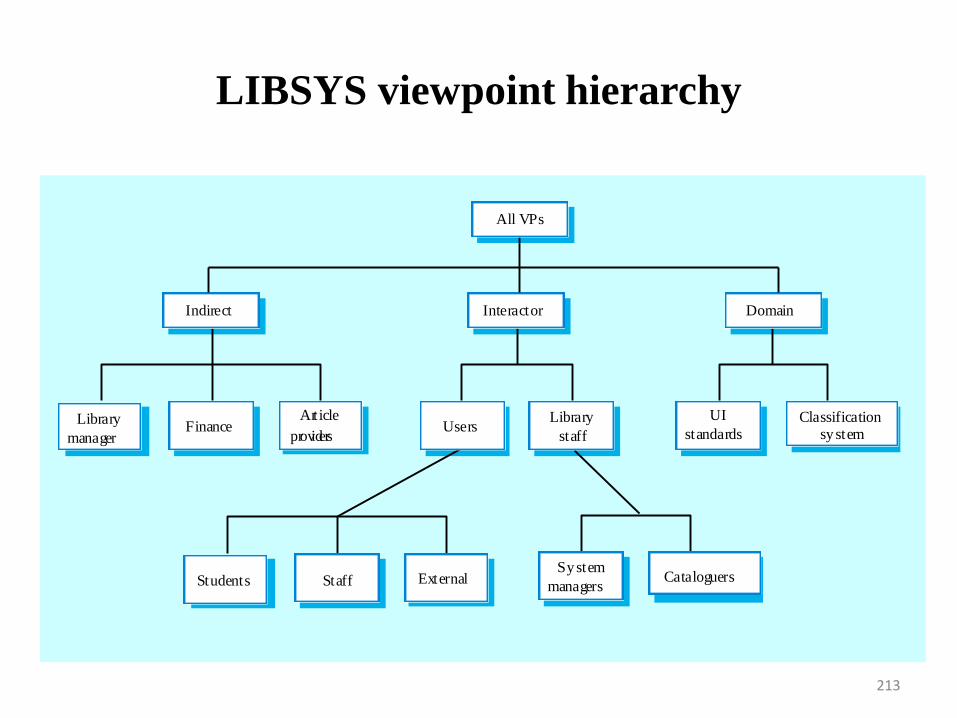
LIBSYS viewpoint hierarchy
213
Article
providersFinance
Library
manager
Library
staffUsers
InteractorIndirect
All VPs
Classificationsystem
UI
standards
Domain
ExternalStaffStudents CataloguersSystem
managers
Interviewing
• The interview is the primary technique for information
gathering during the systems analysis phases of a development
project. It is a skill which must be mastered by every analyst.
• The interviewing skills of the analyst determine what
information is gathered, and the quality and depth of that
information. Interviewing, observation, and research are the
primary tools of the analyst.
• In formal or informal interviewing, the RE team puts questions
to stakeholders about the system that they use and the system
to be developed.
• Interviews are good for getting an overall understanding of
what stakeholders do and how they might interact with the
system.
214
Interviewing
• Goals of the Interview
– At each level, each phase, and with each interviewee, an interview may be conducted to:
• Gather information on the company
• Gather information on the function
• Gather information on processes or activities
• Uncover problems
• Conduct a needs determination
• Verification of previously gathered facts
• Gather opinions or viewpoints
• Provide information
• Obtain leads for further interviews
215
Interviews In Practice
• There are two types of interview
– Closed interviews where a pre-defined set of questions are answered.
– Open interviews where there is no pre-defined agenda and a range of issues are explored with stakeholders.
• Normally a mix of closed and open-ended interviewing is undertaken.
• Interviews are not good for understanding domain requirements
– Requirements engineers cannot understand specific domain terminology;
– Some domain knowledge is so familiar that people find it hard to articulate or think that it isn‟t worth articulating.
216
Interviews
• Effective Interviewers
– Interviewers should be open-minded, willing to listen to stakeholders and should not have pre-conceived ideas about the requirements.
– They should prompt the interviewee with a question or a proposal and should not simply expect them to respond to a question such as „what do you want‟.
• Information form interviews supplement other information about the system from documents, user observations, and so on
• Sometimes, apart from information from documents, interviews may be the only source of information about the system requirements
• It should be used alongside other requirements elicitation techniques
217
Scenarios
• Scenarios are real-life examples of how a system can be used.
• Scenarios can be particularly useful for adding detail to an
outline requirements description.
• Each scenario covers one or more possible interactions
• Several forms of scenarios can be developed, each of which
provides different types of information at different levels of
detail about the system
• Scenarios may be written as text, supplemented by diagrams,
screen shots and so on
218
Scenarios
• Scenarios are real-life examples of how a system can be used.
• A scenario may include
– A description of the starting situation;
– A description of the normal flow of events;
– A description of what can go wrong;
– Information about other concurrent activities that might be going on at the same time
– A description of the system state when the scenario finishes.
219
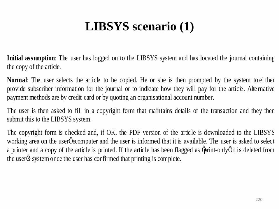
LIBSYS scenario (1)
220
Initial assumption: The user has logged on to the LIBSYS system and has located the journal containing
the copy of the article.
Normal: The user selects the article to be copied. He or she is then prompted by the system to ei ther
provide subscriber information for the journal or to indicate how they will pay for the article. Alte rnative
payment methods are by credit card or by quoting an organisational account number.
The user is then asked to fill in a copyright form that maintains details of the transaction and they then
submit this to the LIBSYS system.
The copyright form is checked and, if OK, the PDF version of the artic le is downloaded to the LIBSYS
working area on the userÕs computer and the user is informed that it is available. The user is asked to select
a pr inter and a copy of the article is printed. If the article has been flagged as Ôprint-onlyÕ it i s deleted from
the userÕs system once the user has confirmed that printing is complete.
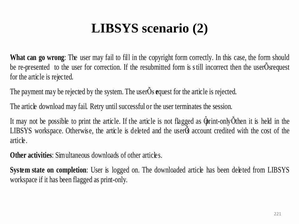
LIBSYS scenario (2)
221
What can go wrong: The user may fail to fill in the copyright form correctly. In this case, the form should
be re-presented to the user for correction. If the resubmitted form is s till incorrect then the userÕs request
for the article is rejected.
The payment may be rejected by the system. The userÕs request for the article is rejected.
The article download may fail. Retry until successful or the user terminates the session.
It may not be possible to print the article. If the article is not flagged as Ôprint-onlyÕ then it is held in the
LIBSYS workspace. Otherwise, the artic le is deleted and the userÕs account credited with the cost of the
article.
Other activities: Simultaneous downloads of other articles.
System state on completion: User is logged on. The downloaded article has been deleted from LIBSYS
workspace if it has been flagged as print-only.
Use cases
• Use-cases are a scenario based technique in the UML which
identify the actors in an interaction and which describe the
interaction itself.
• A set of use cases should describe all possible interactions with
the system.
• Sequence diagrams may be used to add detail to use-cases by
showing the sequence of event processing in the system.
• Use-case approach helps with requirements prioitization
222
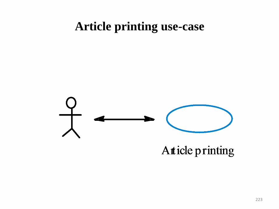
Article printing use-case
223
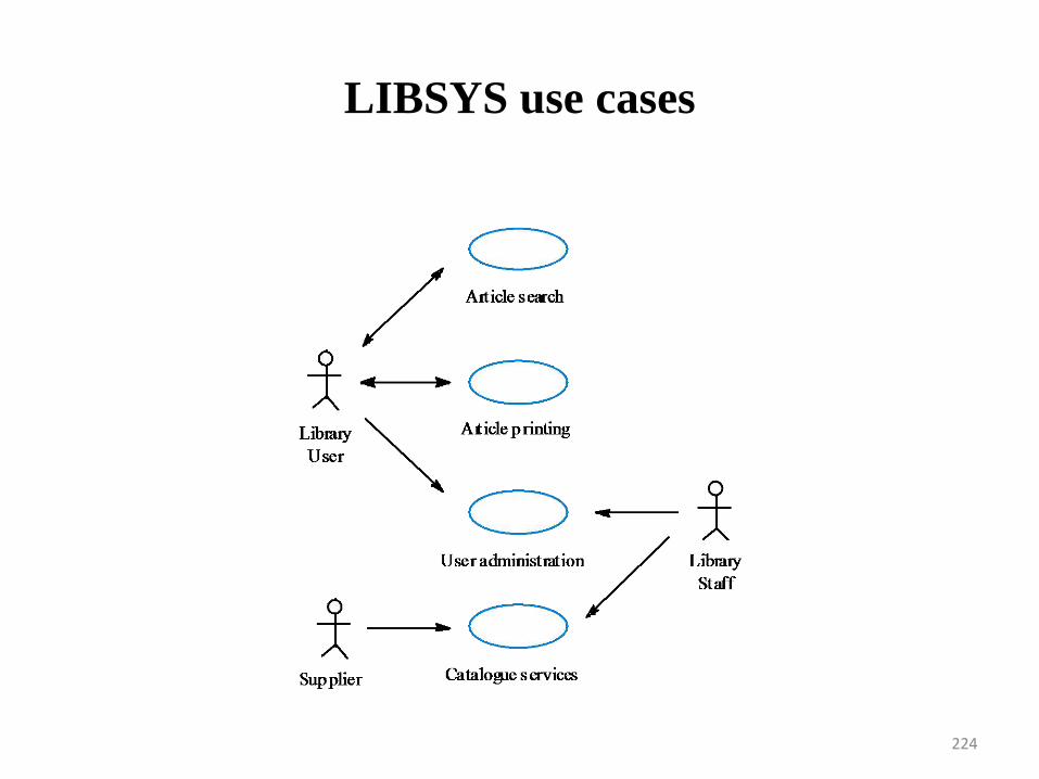
LIBSYS use cases
224
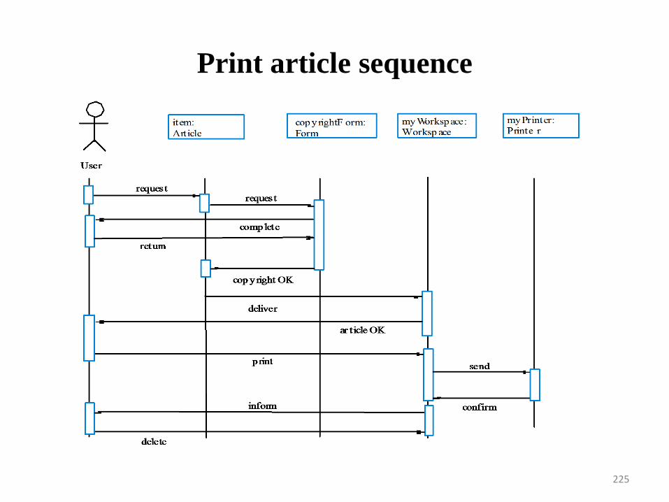
Print article sequence
225
USE CASES
• A Use case can have high priority for
– It describes one of the business process that the
system enables
– Many users will use it frequently
– A favoured user class requested it
– It provides capability that‟s required for regularoty
compliance
– Other system functions depend on its presence
226
Social and organisational factors
• Software systems are used in a social and organisational
context. This can influence or even dominate the system
requirements.
• Social and organisational factors are not a single viewpoint but
have influences on all viewpoints.
• Good analysts must be sensitive to these factors but currently
no systematic way to tackle their analysis.
227
Ethnography
• A social scientists spends a considerable time
observing and analysing how people actually work.
• People do not have to explain or articulate their work.
• Social and organisational factors of importance may
be observed.
• Ethnographic studies have shown that work is usually
richer and more complex than suggested by simple
system models.
228
Focused ethnography
• Developed in a project studying the air traffic controlprocess
• Combines ethnography with prototyping
• Prototype development results in unansweredquestions which focus the ethnographic analysis.
• The problem with ethnography is that it studiesexisting practices which may have some historicalbasis which is no longer relevant.
229
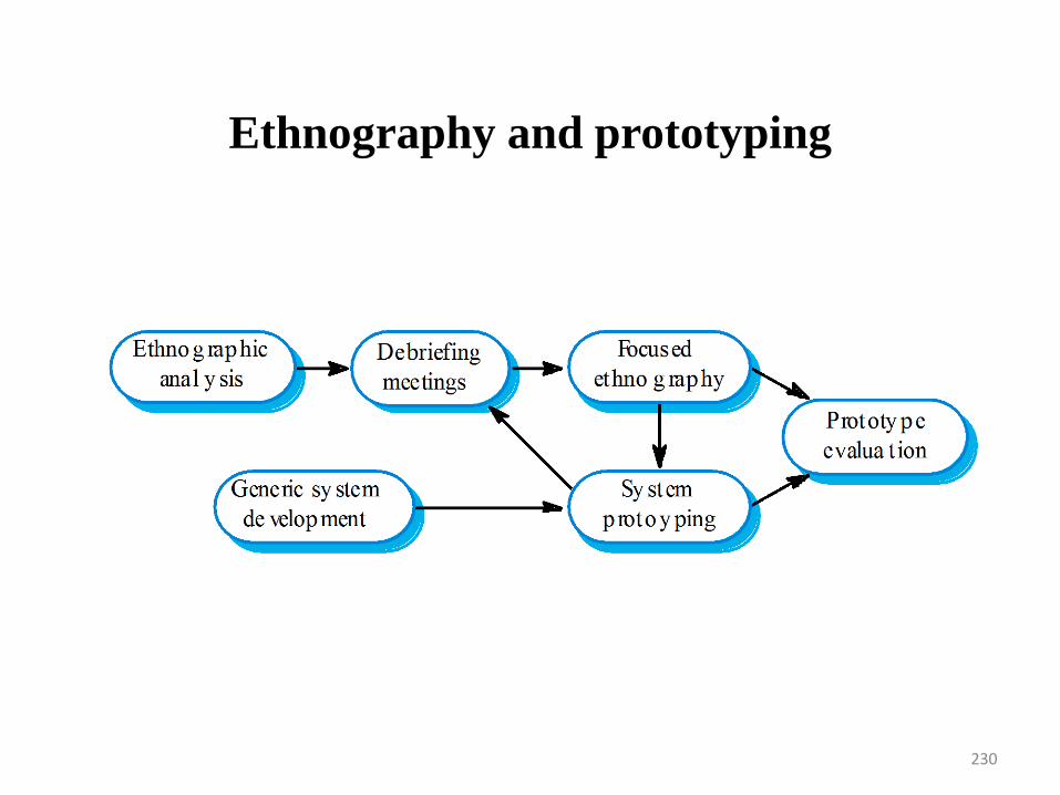
Ethnography and prototyping
230
Scope of Ethnography
• Requirements that are derived from the way
that people actually work rather than the way
which process definitions suggest that they
ought to work.
• Requirements that are derived from
cooperation and awareness of other people‟s
activities.
231
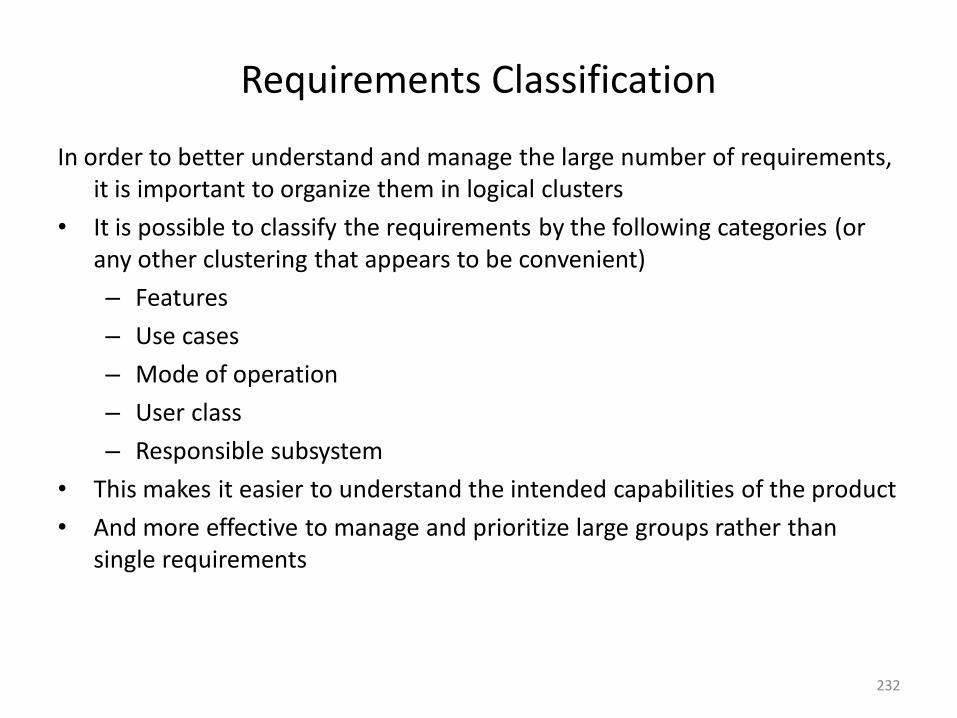
Requirements Classification
In order to better understand and manage the large number of requirements, it is important to organize them in logical clusters
• It is possible to classify the requirements by the following categories (or any other clustering that appears to be convenient)
– Features
– Use cases
– Mode of operation
– User class
– Responsible subsystem
• This makes it easier to understand the intended capabilities of the product
• And more effective to manage and prioritize large groups rather than single requirements
232
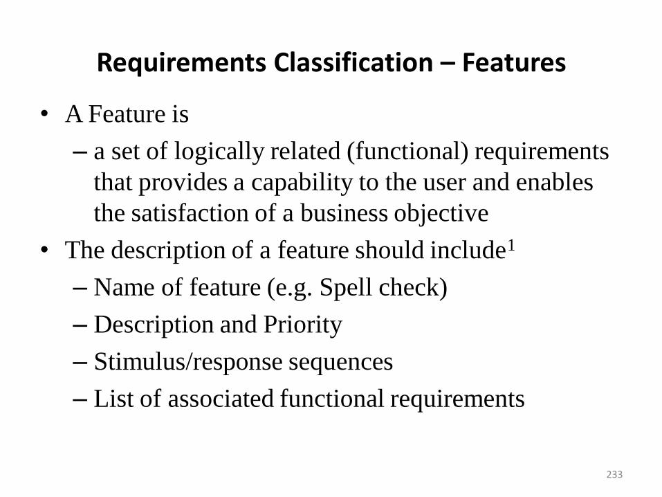
Requirements Classification – Features
• A Feature is
– a set of logically related (functional) requirements
that provides a capability to the user and enables
the satisfaction of a business objective
• The description of a feature should include1
– Name of feature (e.g. Spell check)
– Description and Priority
– Stimulus/response sequences
– List of associated functional requirements
233
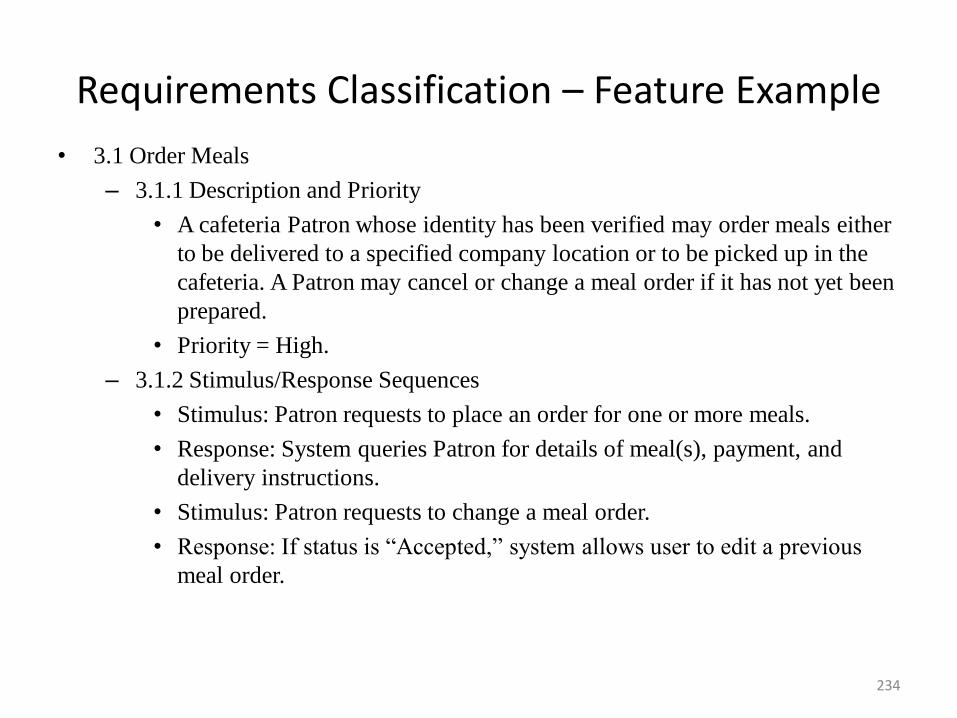
Requirements Classification – Feature Example
• 3.1 Order Meals
– 3.1.1 Description and Priority
• A cafeteria Patron whose identity has been verified may order meals either
to be delivered to a specified company location or to be picked up in the
cafeteria. A Patron may cancel or change a meal order if it has not yet been
prepared.
• Priority = High.
– 3.1.2 Stimulus/Response Sequences
• Stimulus: Patron requests to place an order for one or more meals.
• Response: System queries Patron for details of meal(s), payment, and
delivery instructions.
• Stimulus: Patron requests to change a meal order.
• Response: If status is “Accepted,” system allows user to edit a previous
meal order.
234
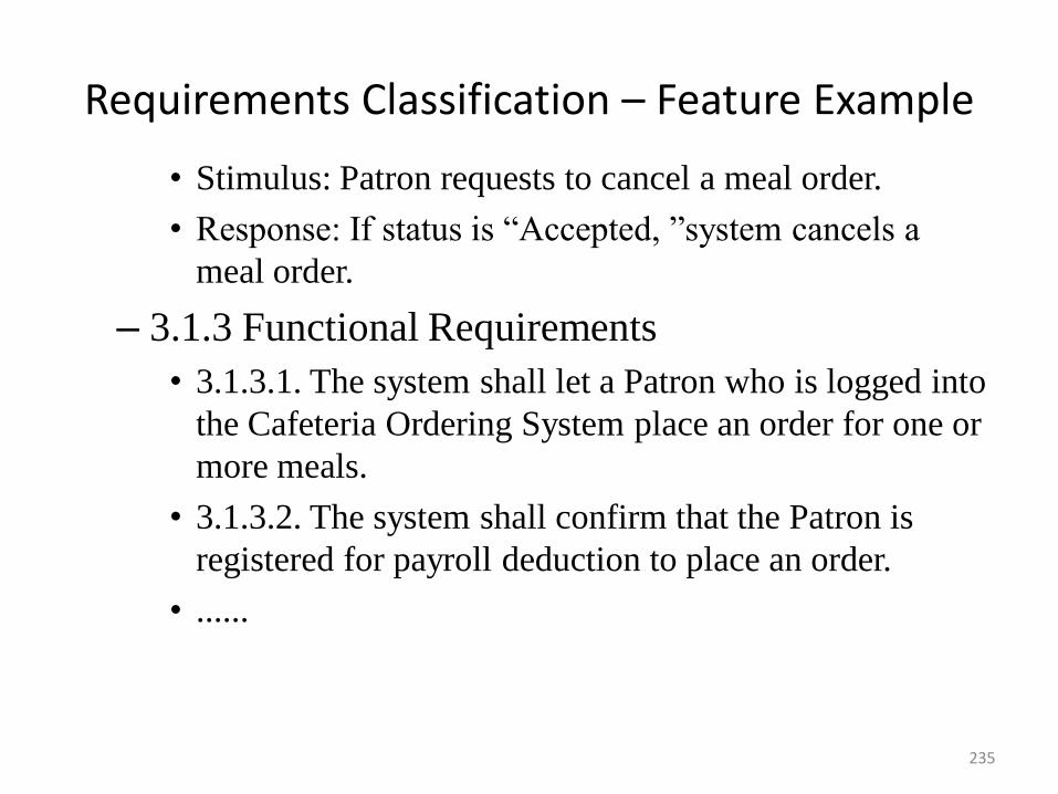
Requirements Classification – Feature Example
• Stimulus: Patron requests to cancel a meal order.
• Response: If status is “Accepted, ”system cancels a
meal order.
– 3.1.3 Functional Requirements
• 3.1.3.1. The system shall let a Patron who is logged into
the Cafeteria Ordering System place an order for one or
more meals.
• 3.1.3.2. The system shall confirm that the Patron is
registered for payroll deduction to place an order.
• ......
235
Requirements Validation
• Concerned with demonstrating that the requirements define the
system that the customer really wants.
• Requirements error costs are high so validation is very
important
– Fixing a requirements error after delivery may cost up to
100 times the cost of fixing an implementation error.
236
Requirements Checking
• Validity. Does the system provide the functions which
best support the customer‟s needs?
• Consistency. Are there any requirements conflicts?
• Completeness. Are all functions required by the
customer included?
• Realism. Can the requirements be implemented given
available budget and technology
• Verifiability. Can the requirements be checked?
237
Requirements Validation Techniques
• Requirements reviews
– Systematic manual analysis of the requirements.
• Prototyping
– Using an executable model of the system to check
requirements.
• Test-case generation
– Developing tests for requirements to check testability.
238
Requirements Reviews
• Regular reviews should be held while the
requirements definition is being formulated.
• Both client and contractor staff should be involved in
reviews.
• Reviews may be formal (with completed documents)
or informal. Good communications between
developers, customers and users can resolve problems
at an early stage.
239
Review Checks
• Verifiability. Is the requirement realistically testable?
• Comprehensibility. Is the requirement properly
understood?
• Traceability. Is the origin of the requirement clearly
stated?
• Adaptability. Can the requirement be changed without
a large impact on other requirements?
240
Requirements Management
• Requirements management is the process of managing
changing requirements during the requirements engineering
process and system development.
• Requirements are inevitably incomplete and inconsistent
– New requirements emerge during the process as business
needs change and a better understanding of the system is
developed;
– Different viewpoints have different requirements and these
are often contradictory.
241
Requirements Change
• The priority of requirements from different
viewpoints changes during the development process.
• System customers may specify requirements from a
business perspective that conflict with end-user
requirements.
• The business and technical environment of the system
changes during its development.
242
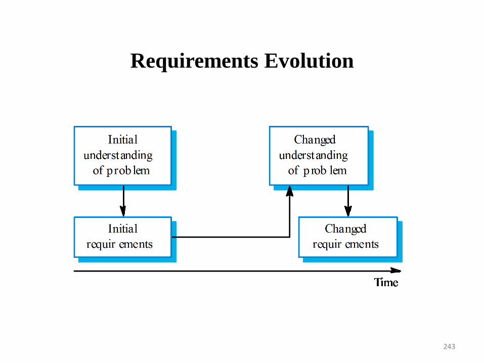
Requirements Evolution
243
244
Enduring and Volatile Requirements
• Enduring requirements
– These are relatively stable requirements that derive from
the core activity of the organization
– Relate directly to the domain of the system
– These requirements may be derived from domain models
that show the entities and relations which characterise an
application domain
– For example, in a hospital there will always be
requirements concerned with patients, doctors, nurses,
treatments, etc
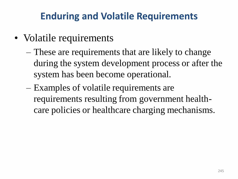
245
Enduring and Volatile Requirements
• Volatile requirements
– These are requirements that are likely to change
during the system development process or after the
system has been become operational.
– Examples of volatile requirements are
requirements resulting from government health-
care policies or healthcare charging mechanisms.
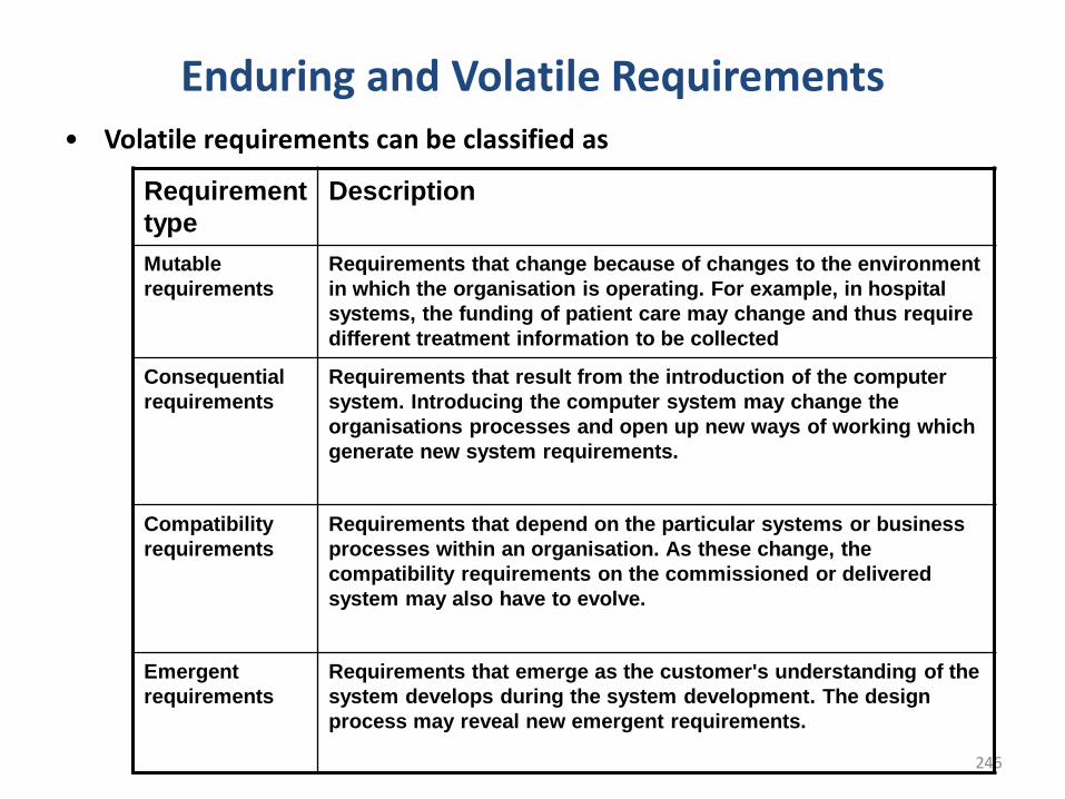
246
Enduring and Volatile Requirements• Volatile requirements can be classified as
Requirement
type
Description
Mutable
requirements
Requirements that change because of changes to the environment
in which the organisation is operating. For example, in hospital
systems, the funding of patient care may change and thus require
different treatment information to be collected
Consequential
requirements
Requirements that result from the introduction of the computer
system. Introducing the computer system may change the
organisations processes and open up new ways of working which
generate new system requirements.
Compatibility
requirements
Requirements that depend on the particular systems or business
processes within an organisation. As these change, the
compatibility requirements on the commissioned or delivered
system may also have to evolve.
Emergent
requirements
Requirements that emerge as the customer's understanding of the
system develops during the system development. The design
process may reveal new emergent requirements.
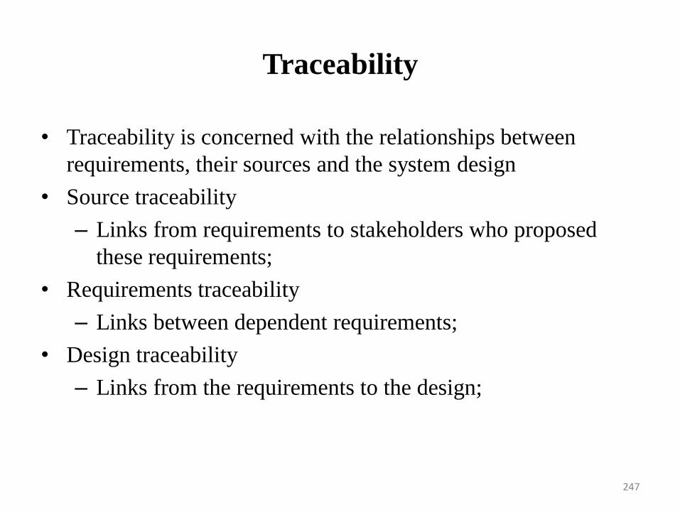
Traceability
• Traceability is concerned with the relationships between
requirements, their sources and the system design
• Source traceability
– Links from requirements to stakeholders who proposed
these requirements;
• Requirements traceability
– Links between dependent requirements;
• Design traceability
– Links from the requirements to the design;
247
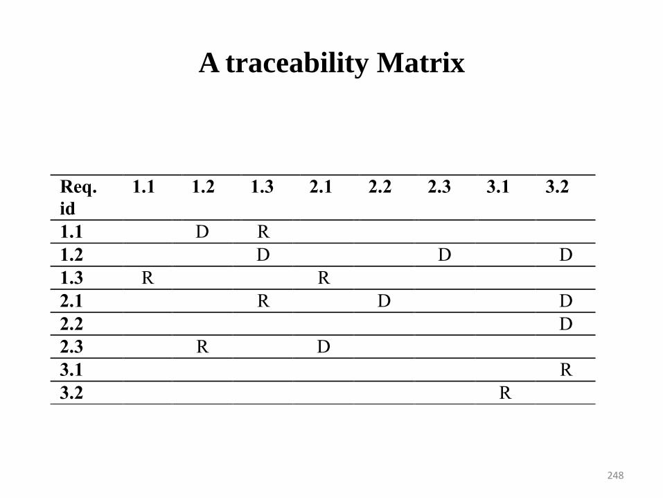
A traceability Matrix
248
Req.
id
1.1 1.2 1.3 2.1 2.2 2.3 3.1 3.2
1.1 D R
1.2 D D D
1.3 R R
2.1 R D D
2.2 D
2.3 R D
3.1 R
3.2 R
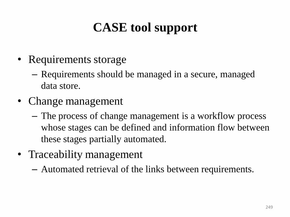
CASE tool support
• Requirements storage
– Requirements should be managed in a secure, managed
data store.
• Change management
– The process of change management is a workflow process
whose stages can be defined and information flow between
these stages partially automated.
• Traceability management
– Automated retrieval of the links between requirements.
249
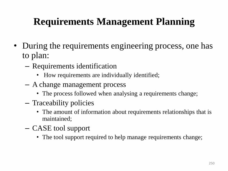
Requirements Management Planning
• During the requirements engineering process, one has to plan:
– Requirements identification• How requirements are individually identified;
– A change management process• The process followed when analysing a requirements change;
– Traceability policies• The amount of information about requirements relationships that is
maintained;
– CASE tool support• The tool support required to help manage requirements change;
250
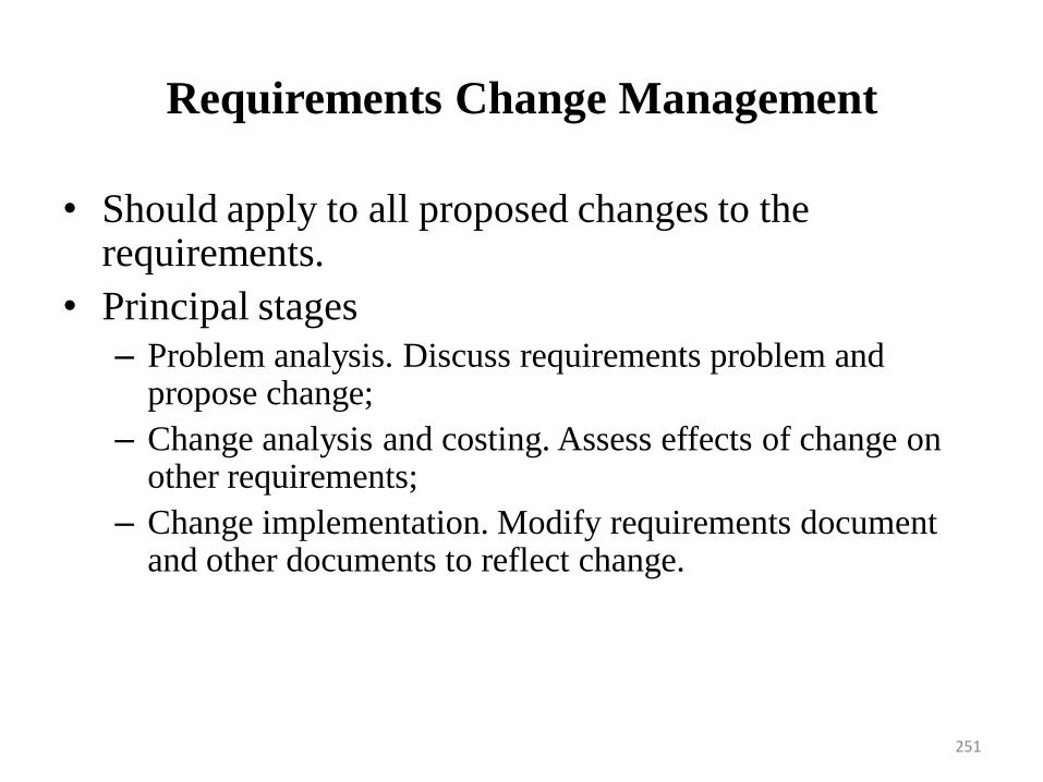
Requirements Change Management
• Should apply to all proposed changes to the requirements.
• Principal stages
– Problem analysis. Discuss requirements problem and propose change;
– Change analysis and costing. Assess effects of change on other requirements;
– Change implementation. Modify requirements document and other documents to reflect change.
251
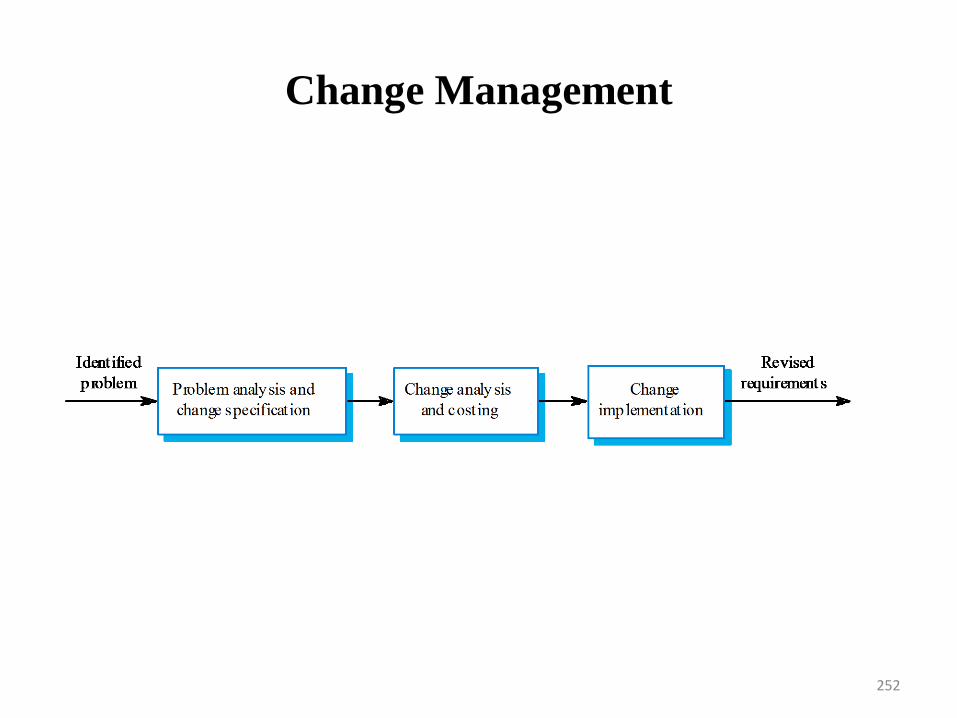
Change Management
252
Classical Analysis• Structured system analysis• Throughout the phases of analysis and design, the analyst should proceed step by
step, obtaining feedback from users and analyzing the design for omissions anderrors.
• Moving too quickly to the next phase may require the analyst to rework portionsof the design that were produced earlier.
• They Structured a project into small, well-defines activities and specify thesequence and interaction of these activities.
• They use diagrammatic and other modeling techniques to give a more precise(structured) definition that is understandable by both users and developers.
• Structured analysis provides a clear requirements statements that everyone canunderstand and is a firm foundation for subsequent design and implementation.
• Part of the problem with systems analysts just asking ‘the right questions’ that it isoften difficult for a technical person to describe the system concepts back to theuser can understand.
• Structured methods generally include the use of easily understood, non technicaldiagrammatic techniques.
• It is important that these diagram do not contain computer jargon and technicaldetail that the user wont understand – and does not need understand.
• Use graphics whenever possible to help communicate better with the user.• Differentiate between logical and physical system.• Build a logical system model to familiarize the user with system characteristics and
interrelationships before implementation.253
Structured system analysis• A Data Flow Diagram (DFD) is a graphical representation of the
"flow" of data through an information system.
• It differs from the system flowchart as it shows the flow of datathrough processes instead of computer hardware.
• It is common practice to draw a System Context Diagram first whichshows the interaction between the system and outside entities.
• The DFD is designed to show how a system is divided into smallerportions and to highlight the flow of data between those parts.
• This context-level Data flow diagram is then "exploded" to showmore detail of the system being modeled. 10
254
High-Level Petri Nets The classical Petri net was invented by Carl Adam Petri in 1962.
A lot of research has been conducted (>10,000 publications).
Until 1985 it was mainly used by theoreticians.
Since the 80’s their practical use has increased because of the introduction of high-level Petri nets and the availability of many tools.
High-level Petri nets are Petri nets extended with
colour (for the modelling of attributes)
time (for performance analysis)
hierarchy (for the structuring of models, DFD's)
255
Why do we need Petri Nets? Petri Nets can be used to rigorously define a system
(reducing ambiguity, making the operations of a system clear, allowing us to prove properties of a system etc.)
They are often used for distributed systems (with several subsystems acting independently) and for systems with resource sharing.
Since there may be more than one transition in thePetri Net active at the same time (and we do notknow which will ‘fire’ first), they are non-deterministic.
256
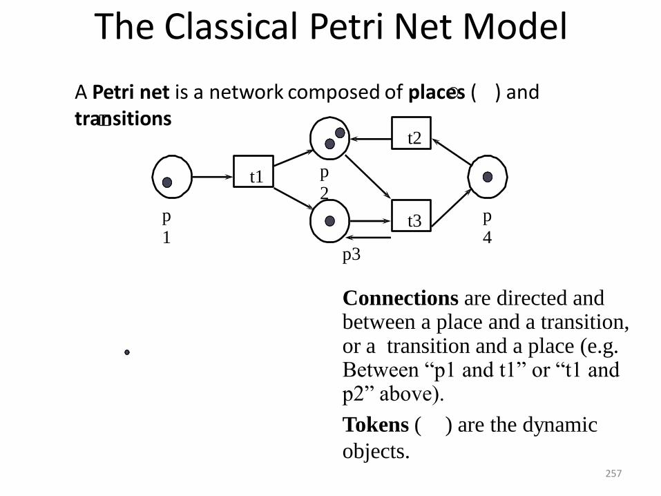
The Classical Petri Net Model
A Petri net is a network composed of places ( ) andtransitions
t2
p
1
p
2
p
4t3
t1
p3
Connections are directed and between a place and a transition, or a transition and a place (e.g. Between “p1 and t1” or “t1 and p2” above).
Tokens ( ) are the dynamic
objects.257
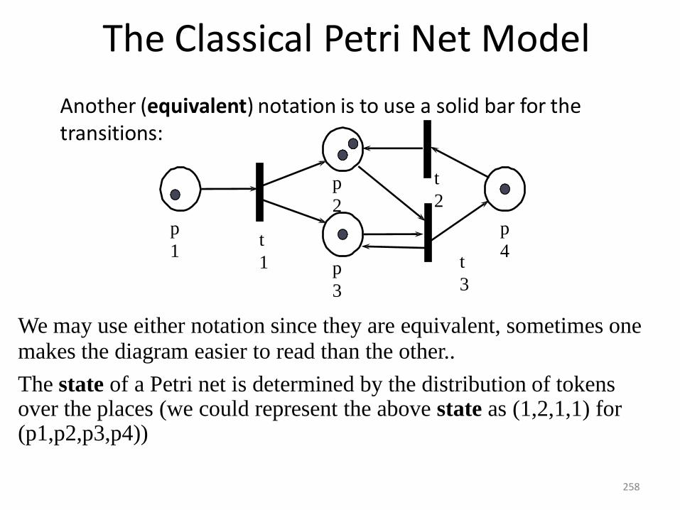
The Classical Petri Net Model
Another (equivalent) notation is to use a solid bar for thetransitions:
t
2
p
1
p
2
p
3
p
4t
3
t
1
We may use either notation since they are equivalent, sometimes one makes the diagram easier to read than the other..
The state of a Petri net is determined by the distribution of tokens over the places (we could represent the above state as (1,2,1,1) for (p1,p2,p3,p4))
258
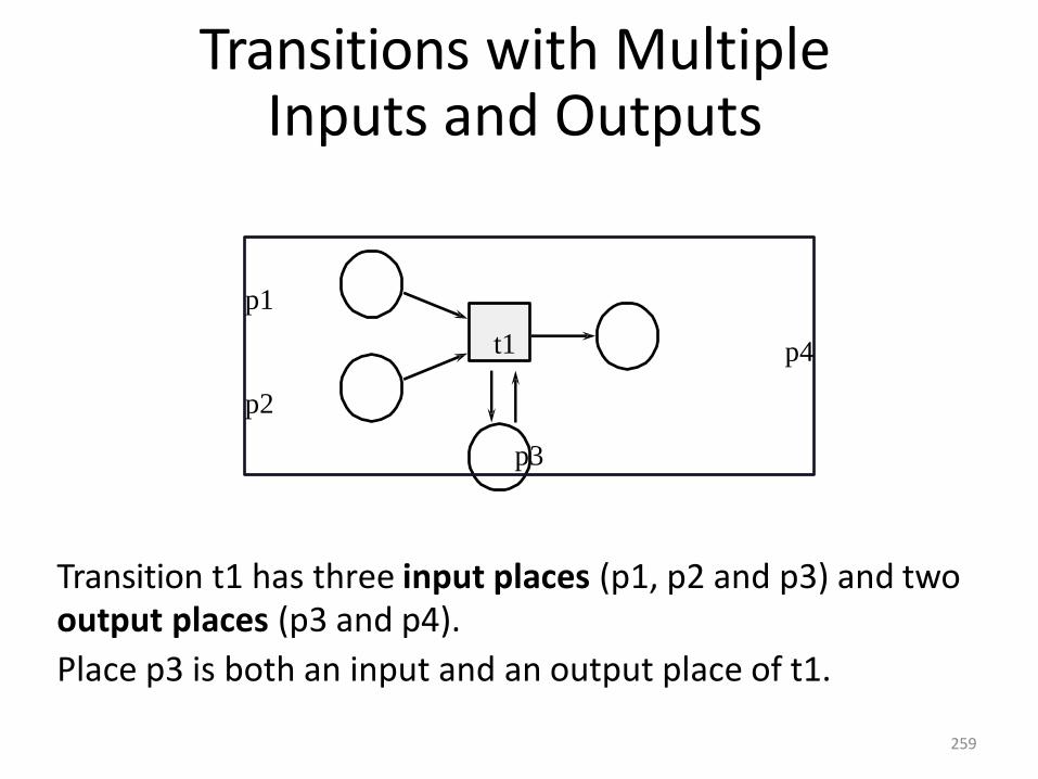
Transition t1 has three input places (p1, p2 and p3) and twooutput places (p3 and p4).
Place p3 is both an input and an output place of t1.
p1
p4
p2
p3
Transitions with MultipleInputs and Outputs
t1
259
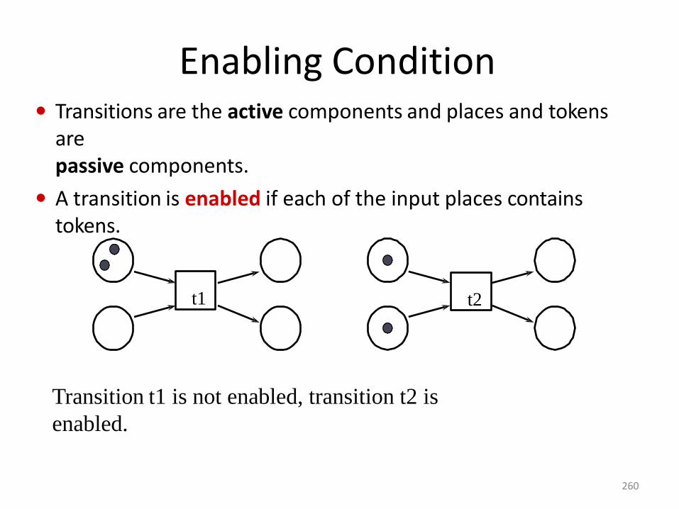
Enabling Condition Transitions are the active components and places and tokens
arepassive components.
A transition is enabled if each of the input places containstokens.
t1 t2
Transition t1 is not enabled, transition t2 is
enabled.
260
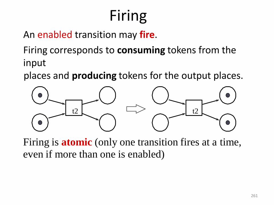
FiringAn enabled transition may fire.
Firing corresponds to consuming tokens from the inputplaces and producing tokens for the output places.
t2t2
Firing is atomic (only one transition fires at a time,
even if more than one is enabled)
261
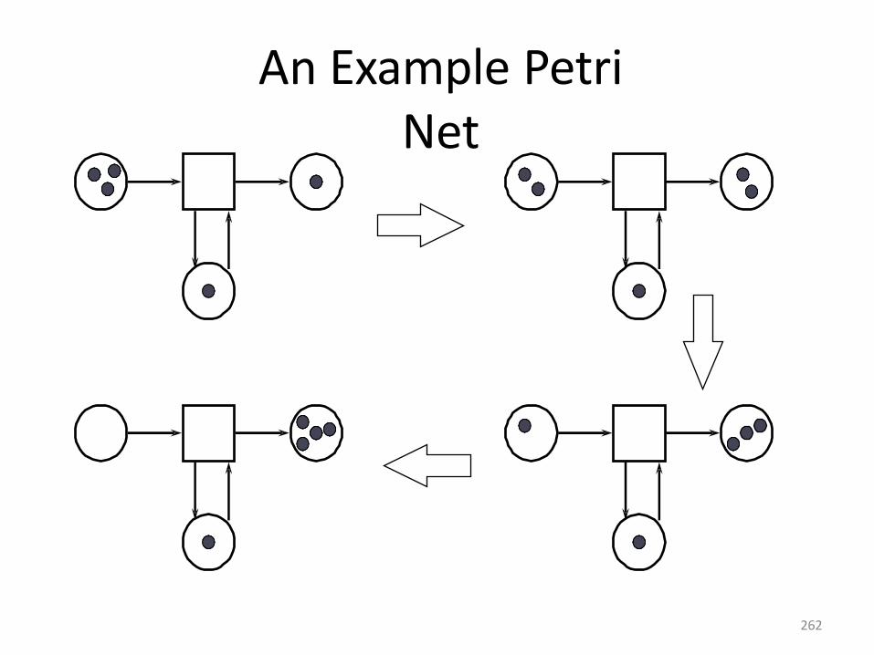
An Example PetriNet
262
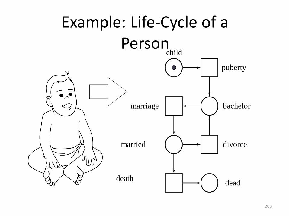
Example: Life-Cycle of aPerson
bachelor
married
child
puberty
marriage
divorce
deathdead
263
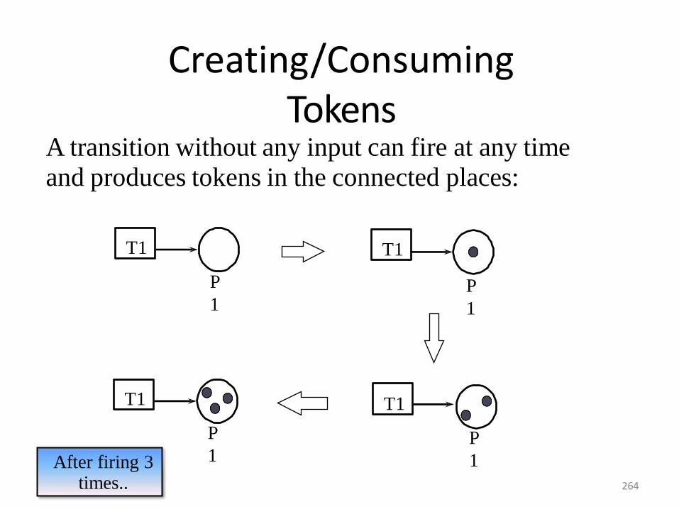
Creating/ConsumingTokens
A transition without any input can fire at any time
and produces tokens in the connected places:
T1
After firing 3 times..
T1
T1T1
P
1P
1
P
1P
1
264
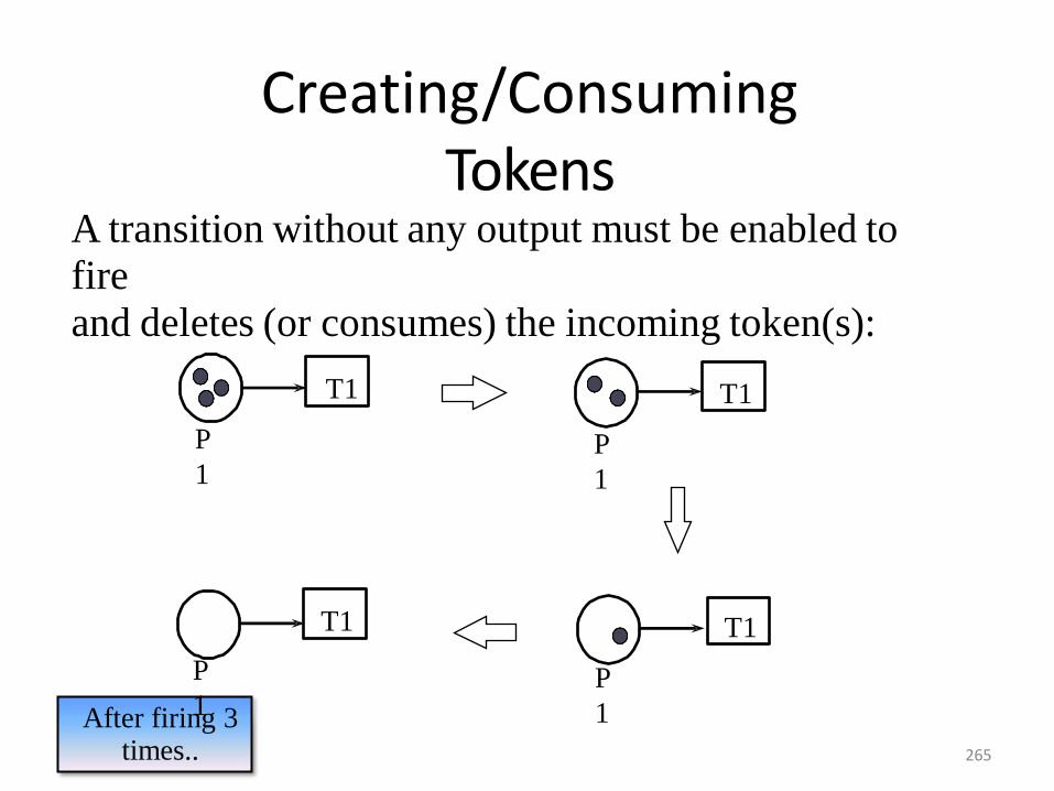
Creating/ConsumingTokens
A transition without any output must be enabled to
fire
and deletes (or consumes) the incoming token(s):
T1
After firing 3 times..
T1
T1 T1
P
1P
1
P
1P
1
265
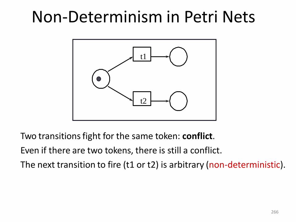
Non-Determinism in Petri Nets
Two transitions fight for the same token: conflict.
Even if there are two tokens, there is still a conflict.
The next transition to fire (t1 or t2) is arbitrary (non-deterministic).
t1
t2
266
Data Dictionary
1. A tool for recording and processing information (metadata) about the
data that an organisation uses.
2. A central catalogue for metadata.
3. Can be integrated within the DBMS or be separate.
4. May be referenced during system design, programming, and by
actively-executing programs.
5. Can be used as a repository for common code (e.g. library routines).
267
Benefits of a DDSBenefits of a DDS are mainly due to the fact that it is a central store of
information about the database.
• Benefits include -
•improved documentation and control
•consistency in data use
•easier data analysis
•reduced data redundancy
•simpler programming
•the enforcement of standards
•better means of estimating the effect of change.
268
DDS FacilitiesA DDS should provide two sets of facilities:
To record and analyse data requirements independently of how they are
going to be met - conceptual data models (entities, attributes, relationships).
To record and design decisions in terms of database or file structures
implemented and the programs which access them - internal schema.
One of the main functions of a DDS is to show the relationship between the
conceptual and implementation views. The mapping should be consistent -
inconsistencies are an error and can be detected here.
269
DD Management With so much detail held on the DDS, it is essential that an indexing and
cross-referencing facility is provided by the DDS.
The DDS can produce reports for use by the data administration staff (to
investigate the efficiency of use and storage of data), systems analysts,
programmers, and users.
DDS can provide a pre-printed form to aid data input into the database
and DD.
A query language is provided for ad-hoc queries. If the DD is tied to the
DBMS, then the query language will be that of the DBMS itself.
270
Management ObjectivesFrom an management point of view, the DDS should
provide facilities for documenting information collected during
all stages of a computer project.
provide details of applications usage and their data usage once a
system has been implemented, so that analysis and redesign may
be facilitated as the environment changes.
make access to the DD information easier than a paper-based
approach by providing cross-referencing and indexing facilities.
make extension of the DD information easier.
encourage systems analysts to follow structured methodologies.
271
Advanced FacilitiesExtra facilities which may be supported by DDS are:Automatic input from source code of data definitions (atcompile time).The recognition that several versions of the same programs ordata structures may exist at the same time.
– live and test states of the programs or data.– programs and data structures which may be used at
different sites.
– data set up under different software or validation routine.
The provision of an interface with a DBMS.Security features such as password protection, to restrict DDSaccess.Generation of update application programs and programs toproduce reports and validation routines.
272
Management Advantages
A number of possible benefits may come from using a DDS:
•improve control and knowledge about the data resource.
•allows accurate assessment of cost and time scale to effect
any changes.
•reduces the clerical load of database administration, and gives
more control
•over the design and use of the database.
•accurate data definitions can be provided securely directly to
programs.
•aid the recording, processing, storage and destruction of data
and associated documents.
273
Management Disadvantages
A DDS is a useful management tool, but at a price.
• The DDS ‟project‟ may itself take two or three years.
• It needs careful planning, defining the exact requirements
designing its contents, testing, implementation and
evaluation.
• The cost of a DDS includes not only the initial price of its
installation and any hardware requirements, but also the cost
of collecting the information entering it into the DDS,
keeping it up-to-date and enforcing standards.
• The use of a DDS requires management
commitment, which is not easy to achieve,
particularly where the benefits are intangible and
long term. 274
UNIT- IIISOFTWARE DESIGN
Design process, Design concepts, design model,
design heuristic, architectural design, architectural
styles, Assessing alternative architectural designs,
and architectural mapping using data flow.
User interface design: Interface analysis, interface
design; Component level design: Designing class
based components, traditional components.
276
Design Engineering
• A good software should exhibit the following properties
– Firmness – A program should not have any bugs thatinhibit its function.
– Commodity – A program should be suitable for thepurposes for which it was intended
– Delight – The experience of using the program should bea pleasurable one.
• The goal of design engineering is to produce a model orrepresentation that exhibits firmness, commodity anddelight. Design engineering for computer software changescontinuously as new methods, better analysis, and broaderunderstanding evolve.
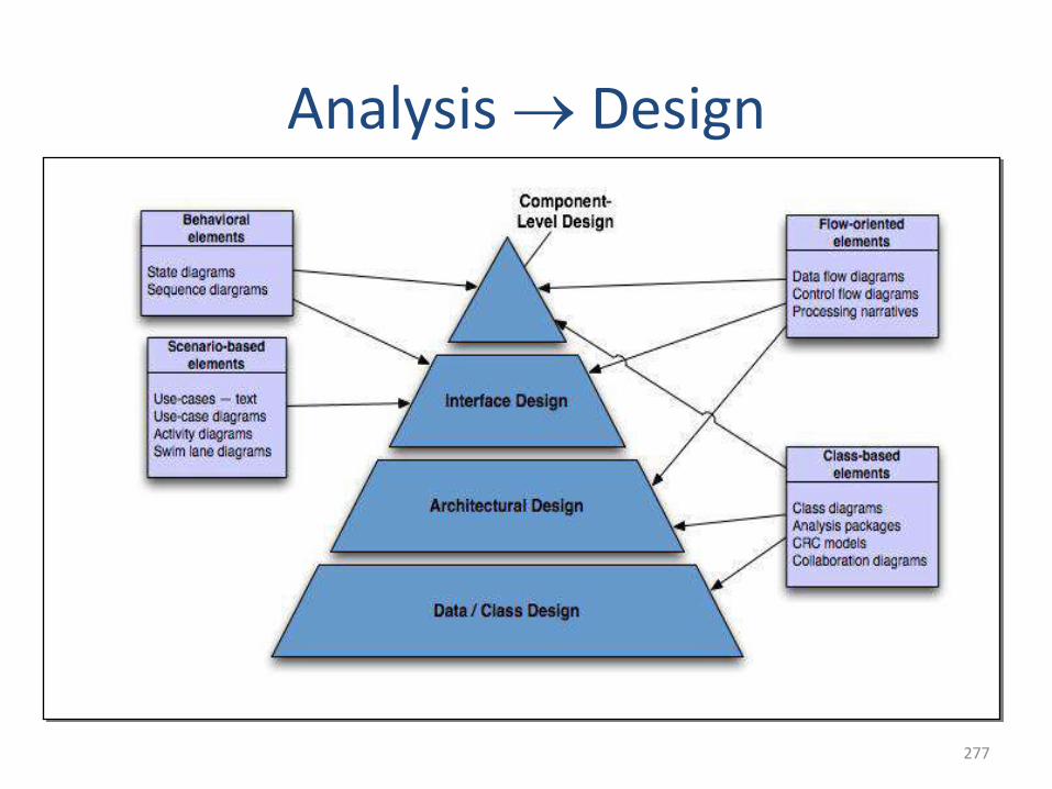
277
277
Analysis Design
278
Design Engineering
• Design creates a representation or model of the software,but unlike the analysis model, the design model providesdetail about software data structures, architecture,interfaces, and components that are necessary to implementthe system
• Design allows a software engineer to model the system orproduct that is to be built
• A design model that encompasses architectural, interface,component-level, and deployment representations is theprimary work product that is produced during softwaredesign
279
Design Engineering
• The design model is assessed by the software team in aneffort to determine whether it contains errors,inconsistencies, or omission, whether better alternativesexist, and whether the model can be implemented withinthe constraints, schedule, and cost that have beenestablished
• Design produces a data /class design, an architecturaldesign, an interface design, and a component design
• Data /analysis design transforms analysis –class models intodesign class realizations and the requisite data structuresrequired to implement the software
280
Design Engineering• The architectural design defines the relationship between
major structural elements of the software, the architecturalstyles and design patterns that can be used to achieve therequirements defined for the system, and the constraintsthat effect the way in which architectural can beimplemented
• The interface design describes how the softwarecommunicates with systems that interoperate with it, andwith humans who use it.
• The component level design transforms structural elementsof the software architecture into a procedural description ofsoftware components
281
The Design Process:• Software design is an iterative process through which requirements are
translated into a “blueprint” for constructing the software. Initially, the blueprint depicts a holistic view of software. That is, the design is represented at ahigh level of abstraction— a level that can be directly traced to the specificsystem objective and more detailed data, functional, and behavioralrequirements.
1. Software Quality Guidelines and Attributes
• Design Guidelines
• A good design should
• exhibit good architectural structure
• be modular
• contain distinct representations of data, architecture, interfaces, and components (modules)
• lead to data structures that are appropriate for the objects to be implemented and be drawn from recognizable design patterns
• lead to components that exhibit independent functional characteristics
• lead to interfaces that reduce the complexity of connections between modules and with the external environment
• be derived using a reputable method that is driven by information obtained during software requirements analysis
282
• Quality Guidelines
• A design should exhibit an architecture that
(1) has been created using recognizable architectural styles or patterns
(2) is composed of components that exhibit good design characteristics (these are discussed later in this chapter), and (3) can be implemented in an evolutionary fashion,2 thereby facilitating implementation and testing.
• A design should be modular; that is, the software should be logically partitioned into elements or subsystems.
• A design should contain distinct representations of data, architecture, interfaces, and components.
• A design should lead to data structures that are appropriate for the classes to be implemented and are drawn from recognizable data patterns.
283
• Quality Guidelines
• A design should lead to components that exhibitindependent functional characteristics.
• A design should lead to interfaces that reduce thecomplexity of connections between components and withthe external environment.
• A design should be derived using a repeatable method thatis driven by information obtained during softwarerequirements analysis.
• A design should be represented using a notation thateffectively communicates its meaning.
284
• Quality attributes
– Functionality is assessed by evaluating the feature set andcapabilities of the program, the generality of the functionsthat are derived and the security of the overall system
– Usability is assessed by considering human factors, overallaesthetics, consistency and documentation
– Reliability is evaluated by measuring the frequency andseverity of failure, the accuracy of output results, the mean-time-to-failure, the ability to recover form failure, and thepredictability of the program.
– Performance is measured by processing speed, response time,resource consumption, throughput, and efficiency
– Supportability combines the ability to extend the program,adaptability, serviceability, testability, compatibility,configurability, the ease with which a system can be installed,and the ease with which problems can be localized
The Design Process:2. The Evolution of Software Design:
• The evolution of software design is a continuing process that has now spanned almost six decades.
• All these methods have a number of common characteristics:
1. a mechanism for the translation of the requirements model into a designrepresentation,
2. a notation for representing functional components and their interfaces,
3. heuristics for refinement and partitioning, and
4. guidelines for quality assessment.
Regardless of the design method that is used, you should apply a set of basicconcepts to data, architectural, interface, and component-level design. Theseconcepts are considered in the sections that follow
286
Design Concepts• A set of fundamental software design concepts has evolved
over the history of software engineering
• Fundamental software design concepts
– Abstraction
– Architecture
– Patterns
– Separation of Concerns
– Modularity
– Information hiding
– Functional independence
– Refinement
– Aspects
– Refactoring
– Object-Oriented Design Concepts
– Design Classes
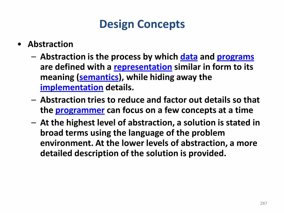
287
Design Concepts
• Abstraction
– Abstraction is the process by which data and programsare defined with a representation similar in form to its meaning (semantics), while hiding away the implementation details.
– Abstraction tries to reduce and factor out details so that the programmer can focus on a few concepts at a time
– At the highest level of abstraction, a solution is stated in broad terms using the language of the problem environment. At the lower levels of abstraction, a more detailed description of the solution is provided.
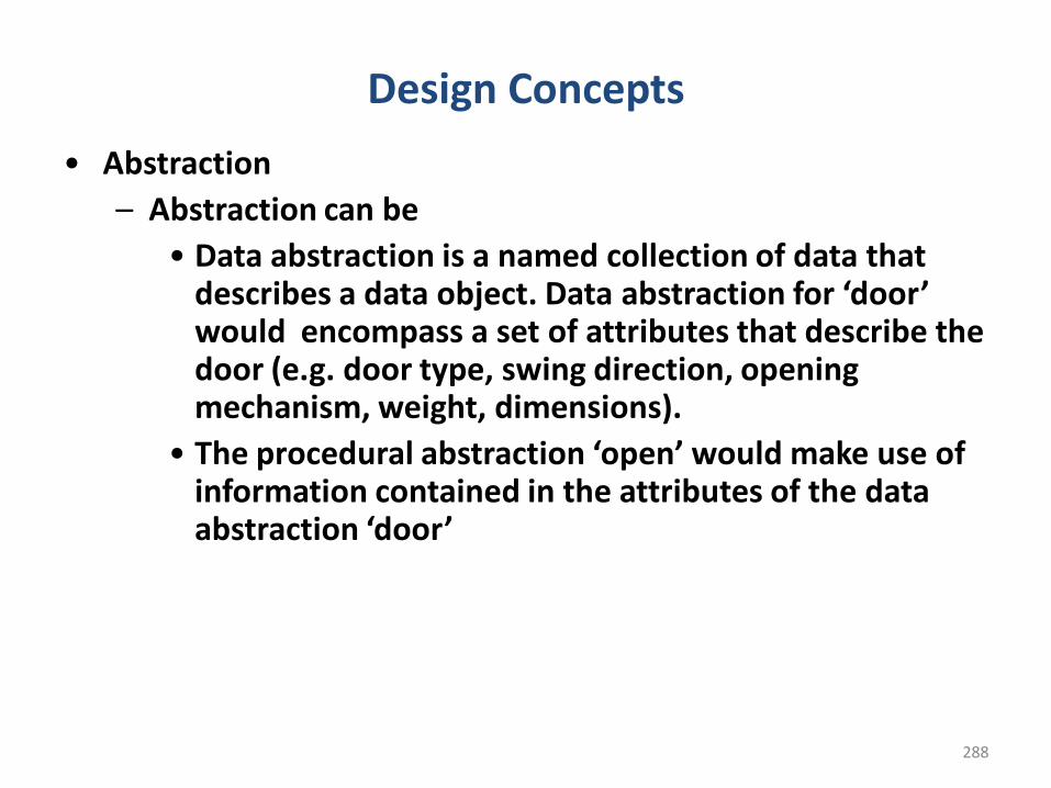
288
Design Concepts
• Abstraction
– Abstraction can be
• Data abstraction is a named collection of data that describes a data object. Data abstraction for ‘door’ would encompass a set of attributes that describe the door (e.g. door type, swing direction, opening mechanism, weight, dimensions).
• The procedural abstraction ‘open’ would make use of information contained in the attributes of the data abstraction ‘door’
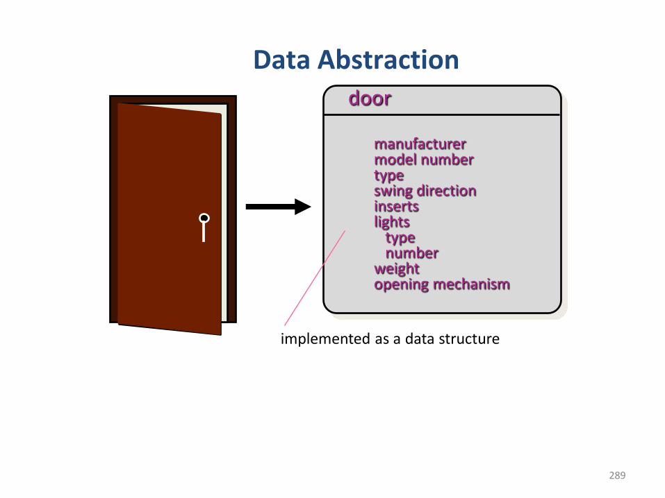
289
Data Abstractiondoor
implemented as a data structure
manufacturermodel numbertypeswing directioninsertslights
typenumber
weightopening mechanism
290
Design Concepts• Abstraction
• Procedural abstraction refers to a sequence ofinstructions that have as specific and limited function. Thename of the procedural abstraction implies thesefunctions, but specific details are suppressed.
e.g. ‘open’ for a door. ‘open’ implies a long sequence ofprocedural steps (e.g. walk to the door, reach out andgrasp knob, turn knob, turn knob and pull door, step awayfrom moving door, etc)
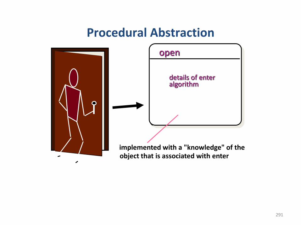
291
Procedural Abstraction
open
implemented with a "knowledge" of the object that is associated with enter
details of enter algorithm
292
Design Concepts
• Architecture
– Architecture is the structure or organization of program components (modules), the manner in which these components interact, and the structure of data that are used by the components. Architectural design can be represented using
• Structural models
• Framework models
• Dynamic models
• Procedural models
• Function models
293
Design Concepts• Architecture
• Structural models represent architecture as an organizedcollection of program components
• Framework models increase the level of design abstractionby attempting to identify repeatable architectural designframeworks that are encountered in similar types ofapplication
• Dynamic models address the behavioural aspects of theprogram architecture, indicating how the structure orsystem configuration may change as a function of externalevents
• Procedural models focus on the design of the business ortechnical process that the system must accommodate
• Function models can be used to represent the functionalhierarchy of a system
294
Design Concepts• Patterns
– Design pattern describes a design structure that solves a particular design problem within a specific context.
– Each design pattern is to provide a description that enables a designer to determine
• Whether the pattern is applicable to the current work
• Whether the pattern can be reused
• Whether the pattern can serve as a guide for developing a similar, but functionally or structurally different pattern
Separation of Concerns
• Separation of concerns is a design concept that suggests thatany complex problem can be more easily handled if it issubdivided into pieces that can each be solved and/oroptimized independently.
• A concern is a feature or behavior that is specified as part ofthe requirements model for the software.
• By separating concerns into smaller, and therefore moremanageable pieces, a problem takes less effort and time tosolve.
• For two problems, p1 and p2, if the perceived complexity of p1is greater than the perceived complexity of p2, it follows thatthe effort required to solve p1 is greater than the effortrequired to solve p2.
Design Concepts
296
Design Concepts• Modularity
– Software is divided into separately named andaddressable components, called modules that areintegrated to satisfy problem requirements
– Design has to be modularized so that development canbe more easily planned, software increments can bedefined and delivered, changes can be more easilyaccommodated, testing and debugging can be conductedmore efficiently and long-term maintenance can beconducted without serious side effects
297
Modular Design
easier to build, easier to change, easier to fix ...
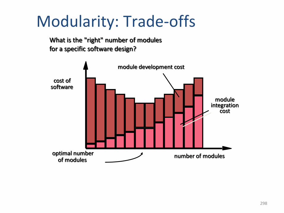
298
Modularity: Trade-offsWhat is the "right" number of modules for a specific software design?
optimal numberof modules
cost ofsoftware
number of modules
moduleintegration
cost
module development cost
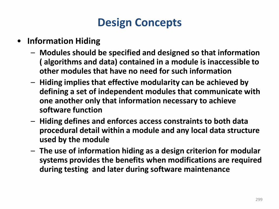
299
Design Concepts
• Information Hiding– Modules should be specified and designed so that information
( algorithms and data) contained in a module is inaccessible to other modules that have no need for such information
– Hiding implies that effective modularity can be achieved by defining a set of independent modules that communicate with one another only that information necessary to achieve software function
– Hiding defines and enforces access constraints to both data procedural detail within a module and any local data structure used by the module
– The use of information hiding as a design criterion for modular systems provides the benefits when modifications are required during testing and later during software maintenance
300
Design Concepts• Information Hiding
• Reduces the likelihood of “side effects”• Limits the global impact of local design
decisions• Emphasizes communication through
controlled interfaces• Discourages the use of global data• Leads to encapsulation—an attribute of high
quality design• Results in higher quality software
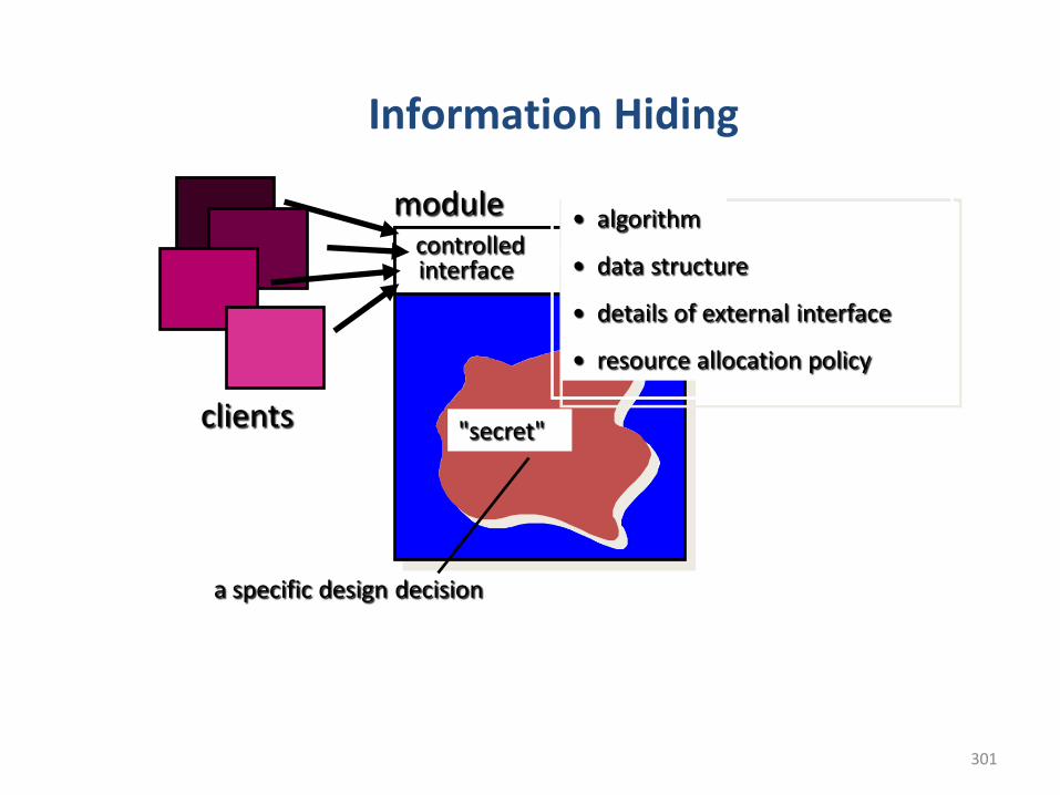
301
Information Hiding
modulecontrolledinterface
"secret"
• algorithm
• data structure
• details of external interface
• resource allocation policy
clients
a specific design decision
302
Design Concepts• Functional Independence
– Functional independence is achieved by developing modules with ‘single minded’ function and avoids excessive interaction with other modules.
– Independent modules are easier to maintain because secondary effects caused by design or code modification are limited, error propagation is reduced
303
Design Concepts• Functional Independence
– Independence is assessed using two qualitative criteria
• Cohesion which is an indication of the relative functional strength of a module. A cohesive module performs a single task, requiring little interaction with other components in other parts of a program
• Coupling is an indication of the relative interdependence among modules. Coupling depends on the interface complexity between modules, the point at which entry or reference is made to a module, and what data pass across the interface
304
Design Concepts• Refinement
– Refinement is a process of elaboration. Refinement causes the designer to elaborate on the original statement, providing more and more detail as each successive refinement occurs.
– Refinement helps the designer to reveal low-level details as design progresses.
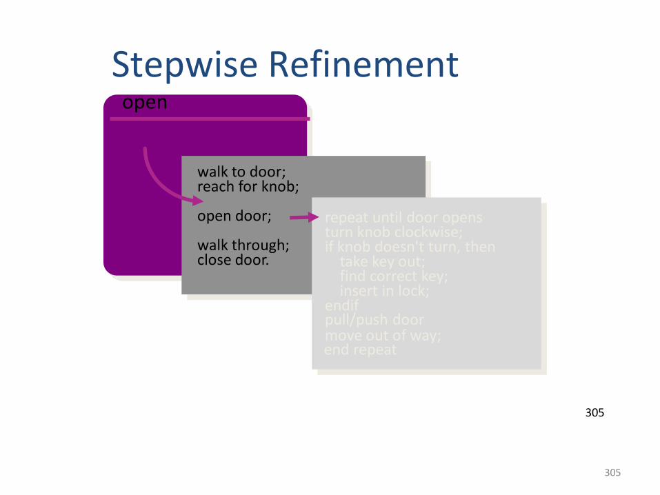
305
305
Stepwise Refinementopen
walk to door;reach for knob;
open door;
walk through;close door.
repeat until door opensturn knob clockwise;if knob doesn't turn, then
take key out;find correct key;insert in lock;
endifpull/push doormove out of way;end repeat
306
Design Concepts
• Refactoring
– Refactoring is the process of changing a software system in such a way that it does not alter the external behaviour of the code yet improves its internal structure
– When software is refactored, the existing design is examined for redundancy, unused design elements, inefficient or unnecessary algorithms, poorly constructed or inappropriate data structures, or any other design failure that can be corrected to yield a better design
•Aspects• As requirements analysis occurs, a set of “concerns” is
uncovered. These concerns “include requirements, use cases,features, data structures, quality-of-service issues, variants,intellectual property boundaries, collaborations, patterns andcontracts”
• Ideally, a requirements model can be organized in a way thatallows you to isolate each concern (requirement) so that it canbe considered independently.
• In practice, however, some of these concerns span the entiresystem and cannot be easily compartmentalized. As designbegins, requirements are refined into a modular designrepresentation.
• Consider two requirements, A and B. Requirement A crosscutsrequirement B “if a software decomposition [refinement] hasbeen chosen in which B cannot be satisfied without taking Ainto account”.
Design Concepts
Design Concepts• Refactoring
• An important design activity suggested for many agilemethods, refactoring is a reorganization technique thatsimplifies the design (or code) of a component withoutchanging its function or behavior
• When software is refactored, the existing design isexamined for redundancy, unused design elements,inefficient or unnecessary algorithms, poorly constructedor inappropriate data structures, or any other designfailure that can be corrected to yield a better design .
Design Concepts
Object-Oriented Design Concepts
• The object-oriented (OO) paradigm is widely used in modernsoftware engineering.
• OO design concepts such as classes and objects, inheritance,messages, and polymorphism, among others.
310
Design Concepts• Design classes
– As the design model evolves, a set of design classes are to be defined that
• Refine the analysis classes by providing design detail that will enable the classes to be implemented
• Create a new set of design classes that implement a software infrastructure to support the business solution
311
Design Concepts• Design classes
– Types of design classes
• User Interface classes define all abstractions that are necessary for human-computer interaction (HCI). Design classes for the interface may be visual representations of the elements of the metaphor
• Business domain classes are refinements of the analysis classes . The classes identify the attributes and services that are required to implement some element of the business domain
• Process classes implement lower-level business abstractions required to fully manage the business domain classes
• Persistent classes represent data stores that will persist beyond the execution of the software
• System classes implement software management and control functions that enable the system to operate and communicate within its computing environment and with the outside world
312
Design Concepts• Design classes
– Characteristics of well-formed design classes
• Complete and sufficient – a design class should be the complete encapsulation of all attributes and methods that can reasonably be expected to exist for the class.
• Primitiveness – methods associated with a design class should be focussed on accomplishing one service for the class. Once the service has been implemented with a method, the class should not provide another way to accomplish the same thing.
• High cohesion – a cohesive design class has a small, focussed set of responsibilities and single-mindedly applies attributes and methods to implement those responsibilities.
• Low coupling – Within the design model, it is necessary for design classes to collaborate with one another collaboration should be kept to an acceptable minimum.
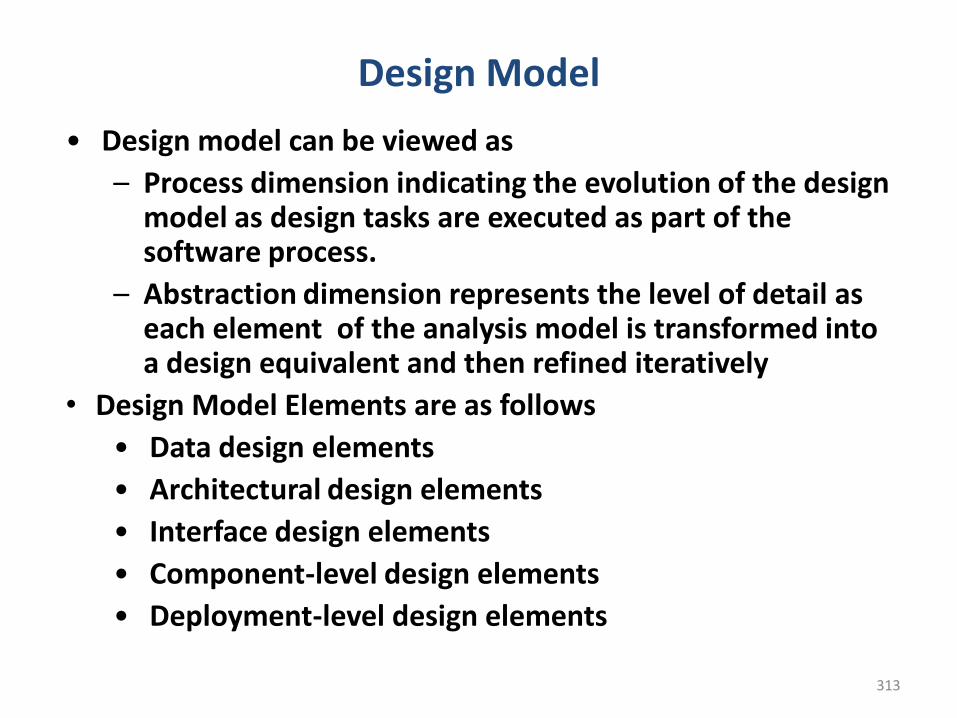
313
Design Model
• Design model can be viewed as
– Process dimension indicating the evolution of the design model as design tasks are executed as part of the software process.
– Abstraction dimension represents the level of detail as each element of the analysis model is transformed into a design equivalent and then refined iteratively
• Design Model Elements are as follows
• Data design elements
• Architectural design elements
• Interface design elements
• Component-level design elements
• Deployment-level design elements
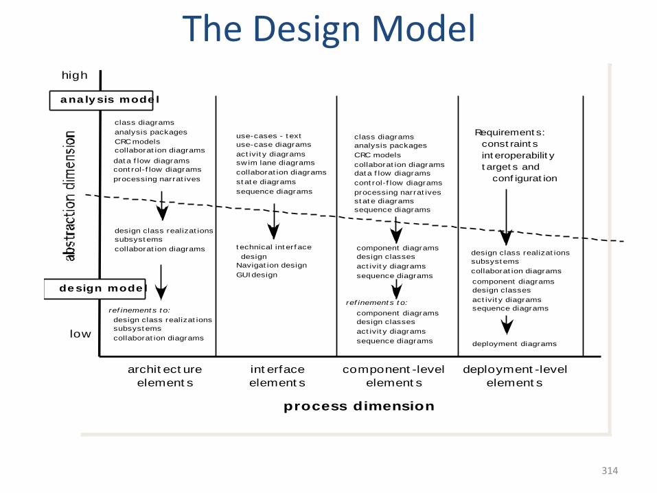
314
314
The Design Model
process dimension
archit ect ure
element s
int erface
element s
component -level
element s
deployment -level
element s
low
high
class diagrams
analysis packages
CRC models
collaborat ion diagrams
use-cases - t ext
use-case diagrams
act ivit y diagrams
sw im lane diagrams
collaborat ion diagrams dat a f low diagrams
cont rol- f low diagrams
processing narrat ives
dat a f low diagrams
cont rol- f low diagrams
processing narrat ives
st at e diagrams
sequence diagrams
st at e diagrams
sequence diagrams
design class realizat ions
subsyst ems
collaborat ion diagrams
design class realizat ions
subsyst ems
collaborat ion diagrams
ref inement s t o:
deployment diagrams
class diagrams
analysis packages
CRC models
collaborat ion diagrams
component diagrams
design classes
act ivit y diagrams
sequence diagrams
ref inement s t o:
component diagrams
design classes
act ivit y diagrams
sequence diagrams
design class realizat ions
subsyst ems
collaborat ion diagrams
component diagrams
design classes
act ivit y diagrams
sequence diagrams
a na ly sis mode l
de sign mode l
Requirement s:
const raint s
int eroperabilit y
t arget s and
conf igurat ion
t echnical int erf ace
design
Navigat ion design
GUI design
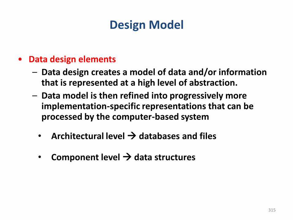
315
Design Model
• Data design elements
– Data design creates a model of data and/or information that is represented at a high level of abstraction.
– Data model is then refined into progressively more implementation-specific representations that can be processed by the computer-based system
• Architectural level databases and files
• Component level data structures
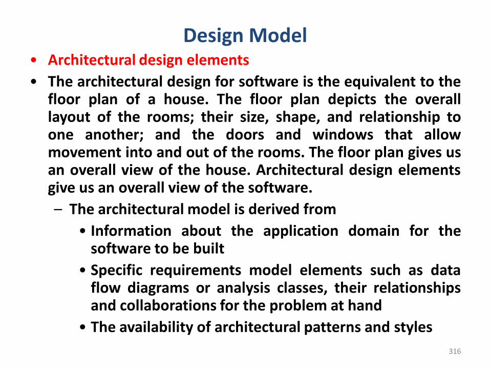
316
Design Model• Architectural design elements
• The architectural design for software is the equivalent to thefloor plan of a house. The floor plan depicts the overalllayout of the rooms; their size, shape, and relationship toone another; and the doors and windows that allowmovement into and out of the rooms. The floor plan gives usan overall view of the house. Architectural design elementsgive us an overall view of the software.
– The architectural model is derived from
• Information about the application domain for thesoftware to be built
• Specific requirements model elements such as dataflow diagrams or analysis classes, their relationshipsand collaborations for the problem at hand
• The availability of architectural patterns and styles
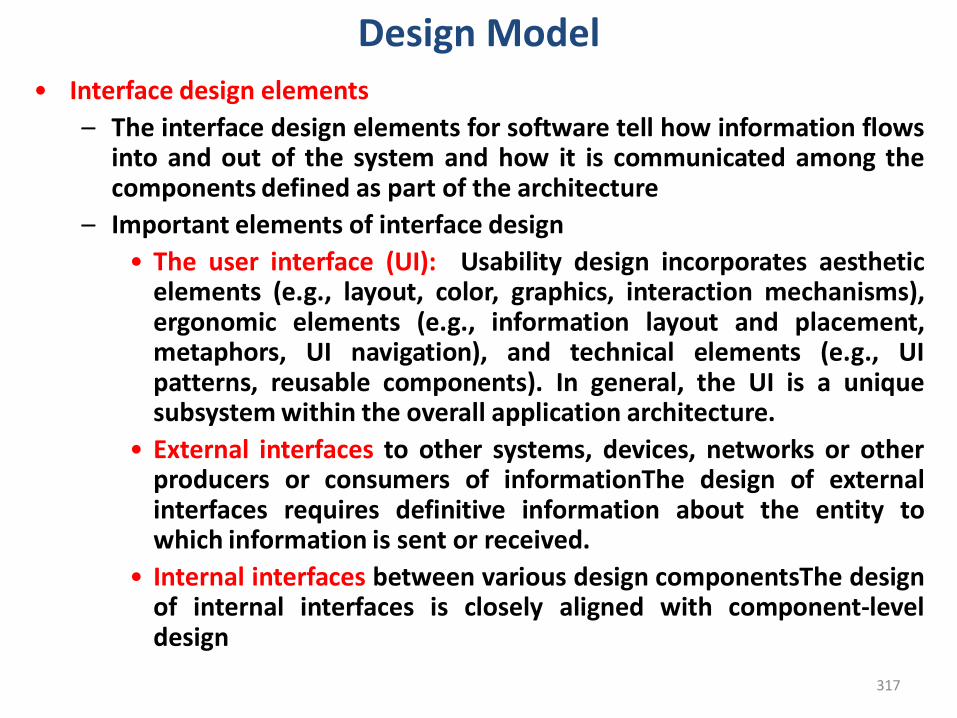
317
Design Model• Interface design elements
– The interface design elements for software tell how information flowsinto and out of the system and how it is communicated among thecomponents defined as part of the architecture
– Important elements of interface design
• The user interface (UI): Usability design incorporates aestheticelements (e.g., layout, color, graphics, interaction mechanisms),ergonomic elements (e.g., information layout and placement,metaphors, UI navigation), and technical elements (e.g., UIpatterns, reusable components). In general, the UI is a uniquesubsystem within the overall application architecture.
• External interfaces to other systems, devices, networks or otherproducers or consumers of informationThe design of externalinterfaces requires definitive information about the entity towhich information is sent or received.
• Internal interfaces between various design componentsThe designof internal interfaces is closely aligned with component-leveldesign
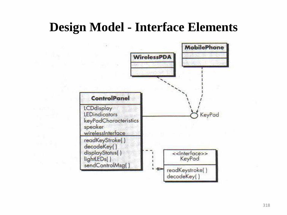
Design Model - Interface Elements
318
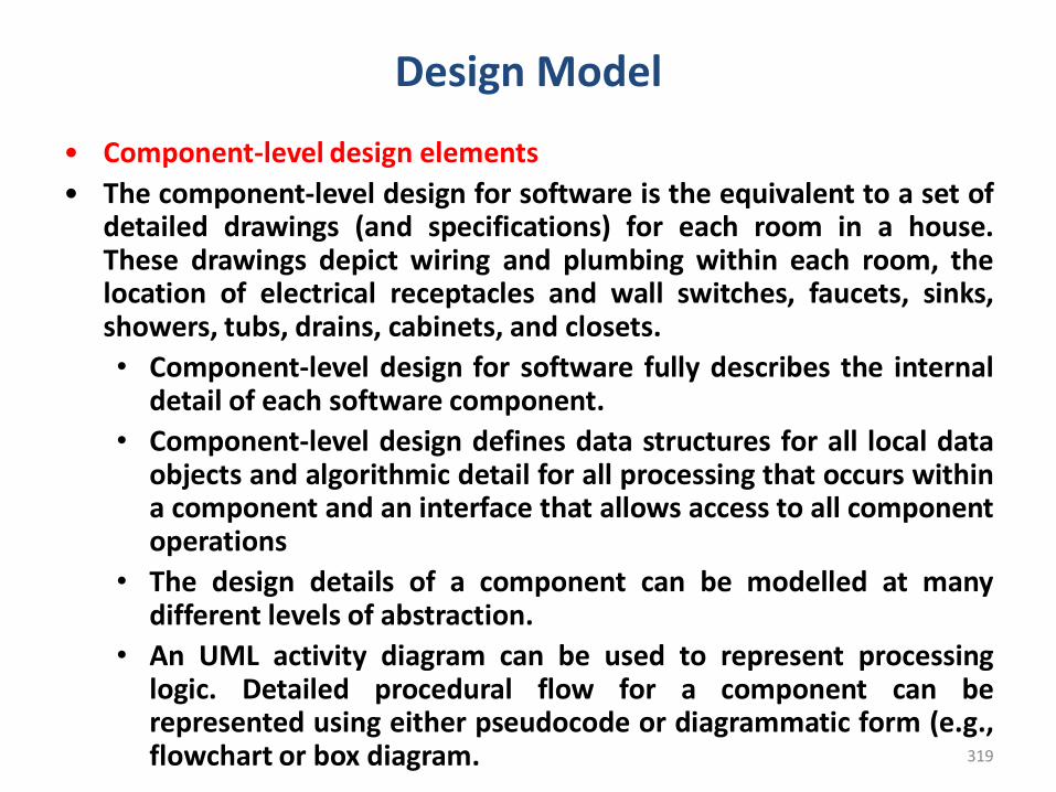
319
Design Model
• Component-level design elements
• The component-level design for software is the equivalent to a set ofdetailed drawings (and specifications) for each room in a house.These drawings depict wiring and plumbing within each room, thelocation of electrical receptacles and wall switches, faucets, sinks,showers, tubs, drains, cabinets, and closets.
• Component-level design for software fully describes the internaldetail of each software component.
• Component-level design defines data structures for all local dataobjects and algorithmic detail for all processing that occurs withina component and an interface that allows access to all componentoperations
• The design details of a component can be modelled at manydifferent levels of abstraction.
• An UML activity diagram can be used to represent processinglogic. Detailed procedural flow for a component can berepresented using either pseudocode or diagrammatic form (e.g.,flowchart or box diagram.
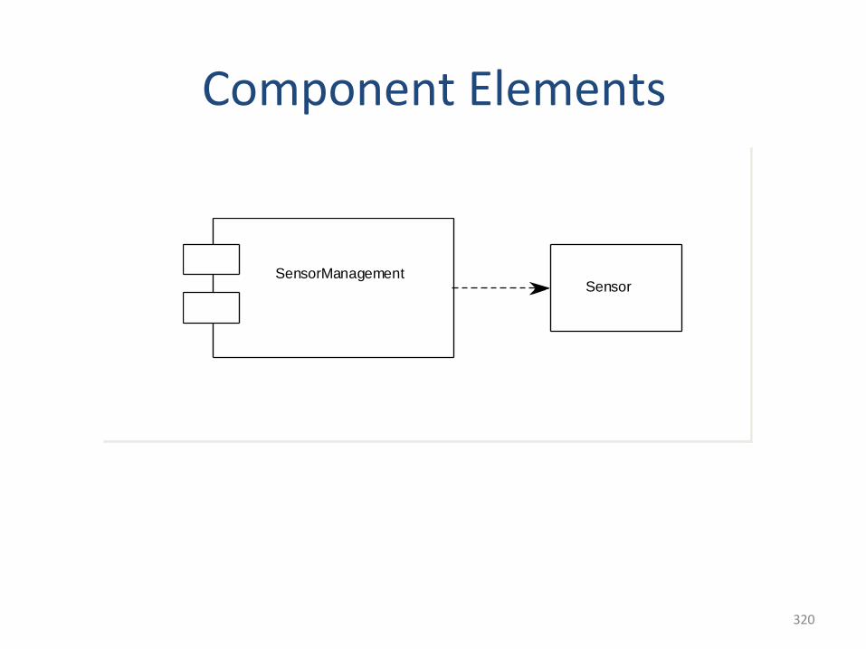
320
Component Elements
SensorManagementSensor
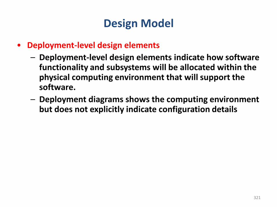
321
Design Model
• Deployment-level design elements
– Deployment-level design elements indicate how software functionality and subsystems will be allocated within the physical computing environment that will support the software.
– Deployment diagrams shows the computing environment but does not explicitly indicate configuration details
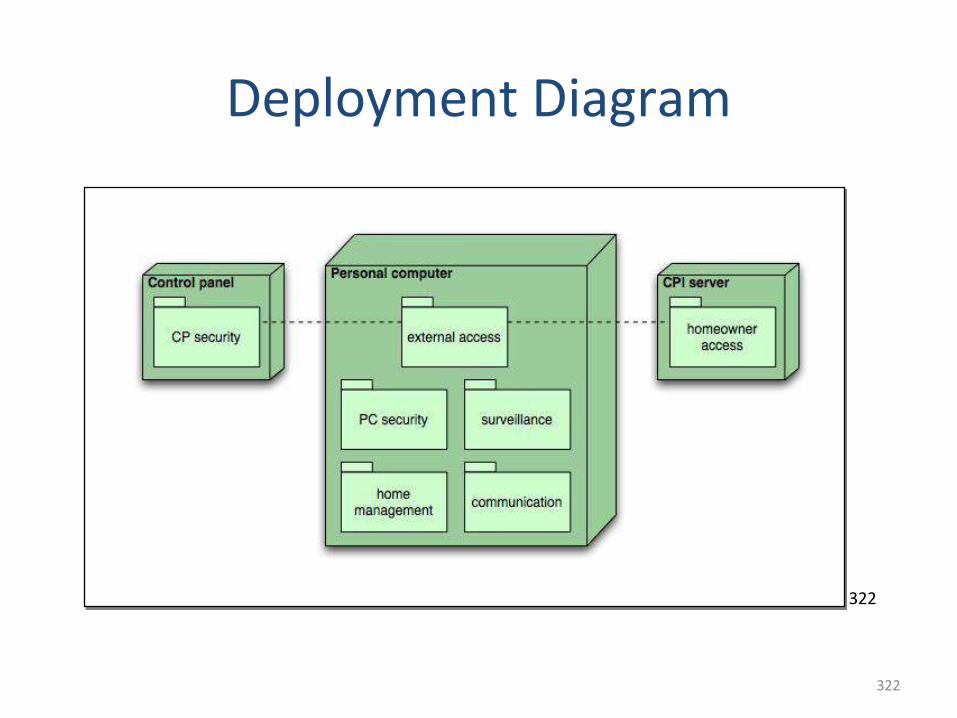
322
322
Deployment Diagram
Creating an architectural design
323
324
Software ArchitectureWhat is software Architecture
• When you consider the architecture of a building, many differentattributes come to mind. At the most simplistic level, you thinkabout the overall shape of the physical structure. But in reality,architecture is much more. It is the manner in which the variouscomponents of the building are integrated to form a cohesivewhole.
• The software architecture of a program or computing system isthe structure or structures of the system, which comprisesoftware components, the externally visible properties of thosecomponents, and the relationships among them
• Software architecture enables to
– Analyze the effectiveness of the design in meeting its stated requirements
– Consider architectural alternatives at a stage when making design changes is still relatively easy
– Reduce the risks associated with the construction of the software
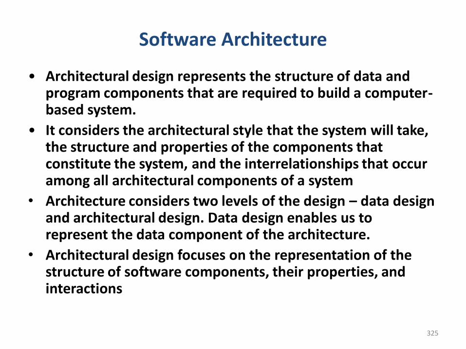
325
Software Architecture
• Architectural design represents the structure of data and program components that are required to build a computer-based system.
• It considers the architectural style that the system will take, the structure and properties of the components that constitute the system, and the interrelationships that occur among all architectural components of a system
• Architecture considers two levels of the design – data design and architectural design. Data design enables us to represent the data component of the architecture.
• Architectural design focuses on the representation of the structure of software components, their properties, and interactions
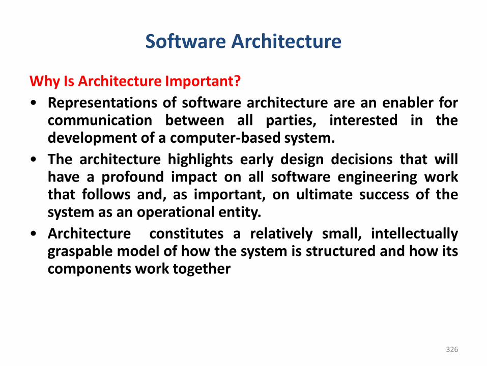
326
Software Architecture
Why Is Architecture Important?
• Representations of software architecture are an enabler forcommunication between all parties, interested in thedevelopment of a computer-based system.
• The architecture highlights early design decisions that willhave a profound impact on all software engineering workthat follows and, as important, on ultimate success of thesystem as an operational entity.
• Architecture constitutes a relatively small, intellectuallygraspable model of how the system is structured and how itscomponents work together
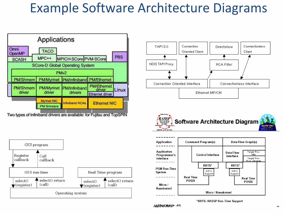
327327
Example Software Architecture Diagrams
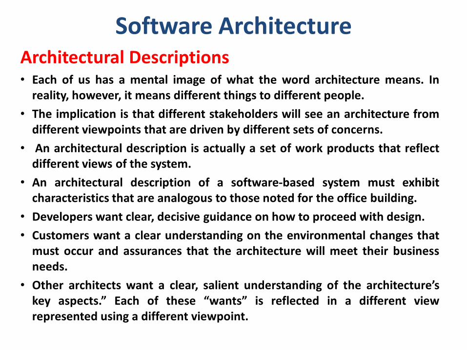
Software ArchitectureArchitectural Descriptions • Each of us has a mental image of what the word architecture means. In
reality, however, it means different things to different people.
• The implication is that different stakeholders will see an architecture fromdifferent viewpoints that are driven by different sets of concerns.
• An architectural description is actually a set of work products that reflectdifferent views of the system.
• An architectural description of a software-based system must exhibitcharacteristics that are analogous to those noted for the office building.
• Developers want clear, decisive guidance on how to proceed with design.
• Customers want a clear understanding on the environmental changes thatmust occur and assurances that the architecture will meet their businessneeds.
• Other architects want a clear, salient understanding of the architecture’skey aspects.” Each of these “wants” is reflected in a different viewrepresented using a different viewpoint.
Software Architecture
Architectural Decisions
• Each view developed as part of an architectural descriptionaddresses a specific stakeholder concern.
• To develop each view (and the architectural description as awhole) the system architect considers a variety ofalternatives and ultimately decides on the specificarchitectural features that best meet the concern.
• Therefore, architectural decisions themselves can beconsidered to be one view of the architecture.
• The reasons that decisions were made provide insight intothe structure of a system and its conformance tostakeholder concerns.
330
Software Architectural Styles1. A Brief Taxonomy of Architectural Styles2. Architectural Patterns3. Organization and Refinement
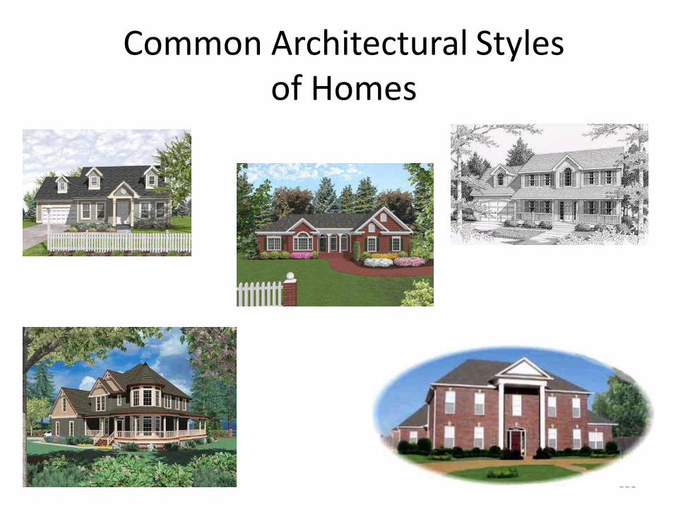
331
Common Architectural Stylesof Homes
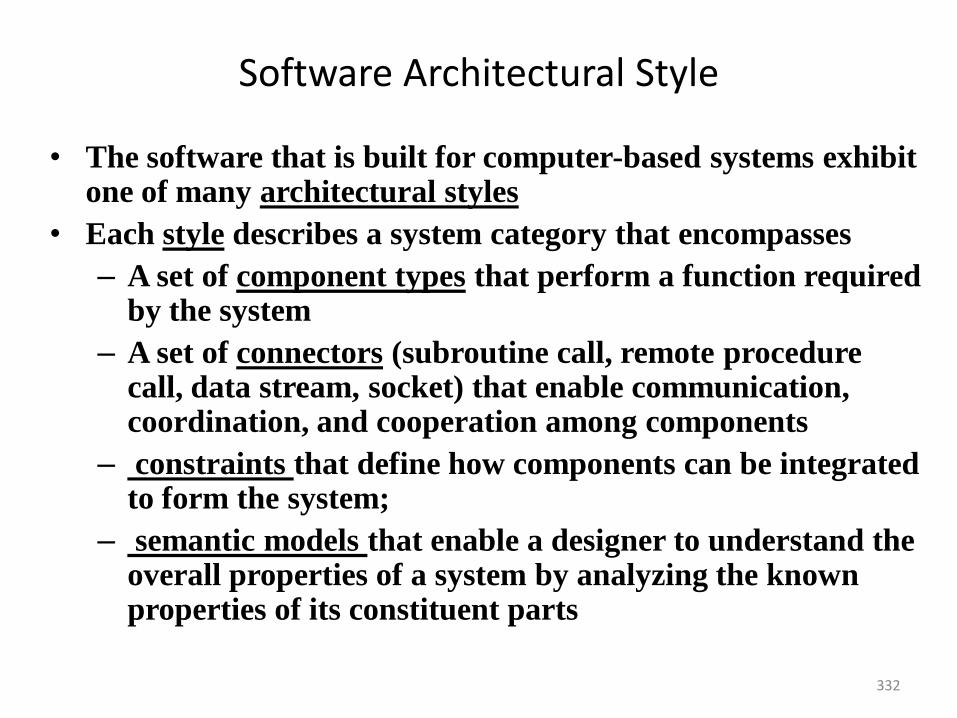
332
Software Architectural Style
• The software that is built for computer-based systems exhibit one of many architectural styles
• Each style describes a system category that encompasses
– A set of component types that perform a function required by the system
– A set of connectors (subroutine call, remote procedure call, data stream, socket) that enable communication, coordination, and cooperation among components
– constraints that define how components can be integrated to form the system;
– semantic models that enable a designer to understand the overall properties of a system by analyzing the known properties of its constituent parts
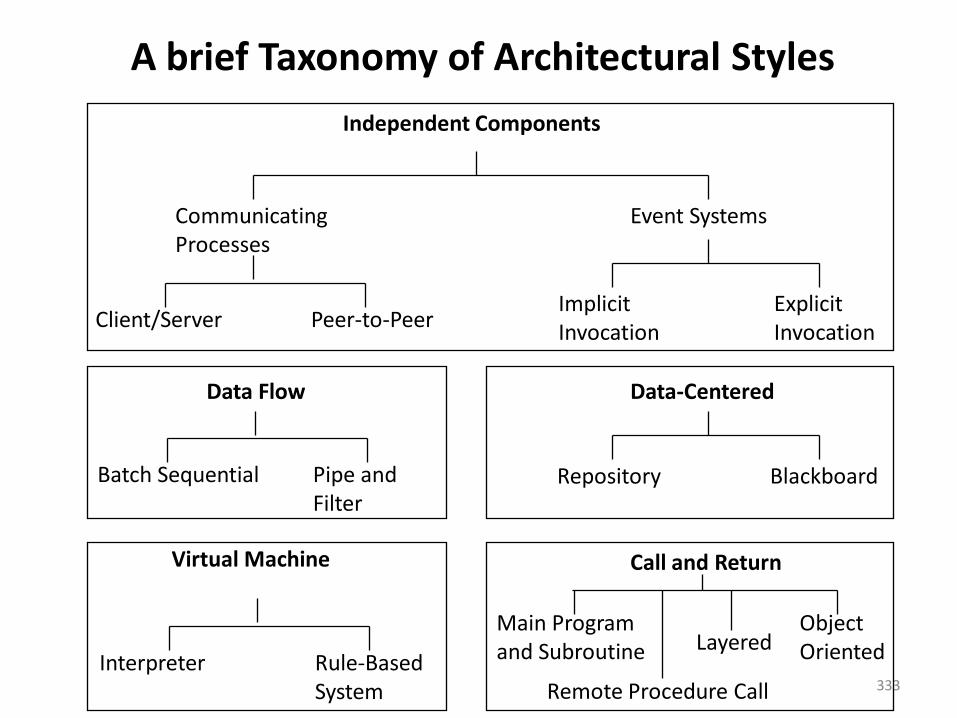
333
A brief Taxonomy of Architectural Styles
Independent Components
CommunicatingProcesses
Event Systems
Client/Server Peer-to-PeerImplicitInvocation
ExplicitInvocation
Data Flow
Batch Sequential Pipe andFilter
Virtual Machine
Interpreter Rule-BasedSystem
Data-Centered
Repository Blackboard
Call and Return
Main Programand Subroutine
ObjectOrientedLayered
Remote Procedure Call
Software Architectural Style
A Brief Taxonomy of Architectural Styles
• Data-centered architectures. A data store (e.g., a file ordatabase) resides at the center of this architecture and isaccessed frequently by other components that update, add,delete, or otherwise modify data within the store.
• illustrates a typical data-centered style. Client software accessesa central repository. In some cases the data repository ispassive. That is, client software accesses the data independentof any changes to the data or the actions of other clientsoftware. A variation on this approach transforms therepository into a “blackboard
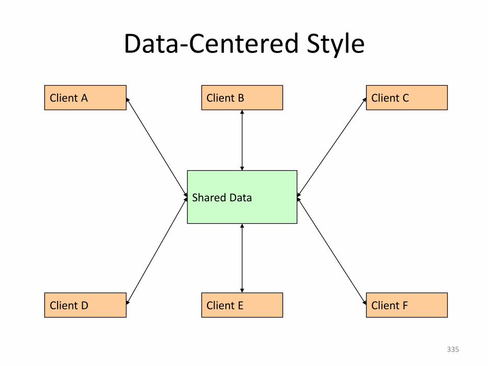
335
Data-Centered Style
Shared Data
Client A Client B Client C
Client D Client E Client F
Software Architectural Style
• Data-flow architectures. • This architecture is applied when input data are to be• transformed through a series of computational or
manipulative components into output data. • A pipe-and-filter pattern shows has a set of
components, called filters, connected by pipes that transmit data from one component to the next.
• Each filter works independently of those components upstream and downstream, is designed to expect data input of a certain form, and produces data output (to the next filter) of a specified form.
• However, the filter does not require knowledge of the workings of its neighboring filters.
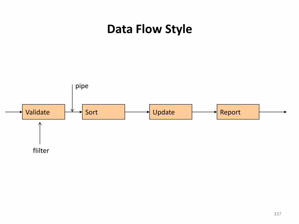
337
Data Flow Style
Validate Sort Update Report
fIilter
pipe
Software Architectural Style
• Call and return architectures.
• This architectural style enables you to achieve a programstructure that is relatively easy to modify and scale.
• A number of substyles exist within this category:
• Main program/subprogram architectures: This classicprogram structure decomposes function into a controlhierarchy where a “main” program invokes a number ofprogram components that in turn may invoke still othercomponents. Figure illustrates an architecture of this type.
• Remote procedure call architectures: The components of amain program/subprogram architecture are distributed acrossmultiple computers on a network.
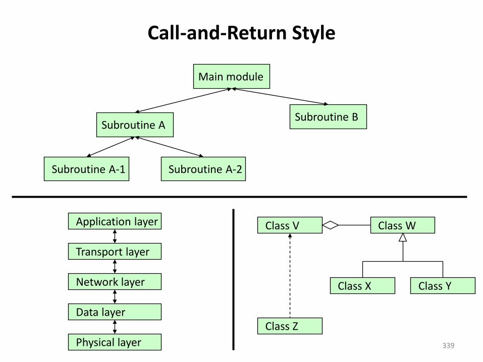
339
Call-and-Return Style
Main module
Subroutine ASubroutine B
Subroutine A-1 Subroutine A-2
Physical layer
Data layer
Network layer
Transport layer
Application layer Class WClass V
Class X
Class Z
Class Y
Software Architectural Style• Object-oriented architectures. • The components of a system encapsulate data and the
operations that must be applied to manipulate the data.
• Communication and coordination between components are accomplished via message passing.
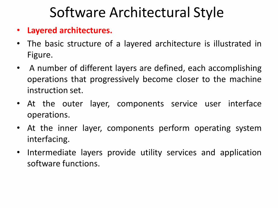
Software Architectural Style• Layered architectures.
• The basic structure of a layered architecture is illustrated inFigure.
• A number of different layers are defined, each accomplishingoperations that progressively become closer to the machineinstruction set.
• At the outer layer, components service user interfaceoperations.
• At the inner layer, components perform operating systeminterfacing.
• Intermediate layers provide utility services and applicationsoftware functions.
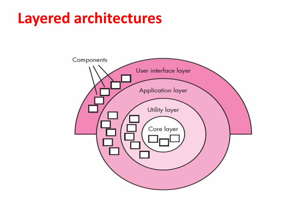
Layered architectures
343
Architectural Patterns
• As the requirements model is developed, you’ll notice that thesoftware must address a number of broad problems that span theentire application.
• For example, the requirements model for virtually every e-commerceapplication is faced with the following problem: How do we offer abroad array of goods to a broad array of customers and allow thosecustomers to purchase our goods online?
• Architectural patterns address an application-specific problem withina specific context and under a set of limitations and constraints. Thepattern proposes an architectural solution that can serve as the basisfor architectural design.
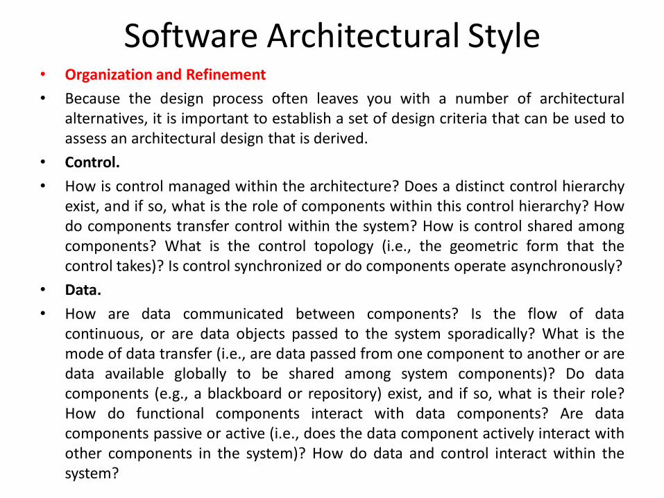
Software Architectural Style• Organization and Refinement
• Because the design process often leaves you with a number of architecturalalternatives, it is important to establish a set of design criteria that can be used toassess an architectural design that is derived.
• Control.
• How is control managed within the architecture? Does a distinct control hierarchyexist, and if so, what is the role of components within this control hierarchy? Howdo components transfer control within the system? How is control shared amongcomponents? What is the control topology (i.e., the geometric form that thecontrol takes)? Is control synchronized or do components operate asynchronously?
• Data.
• How are data communicated between components? Is the flow of datacontinuous, or are data objects passed to the system sporadically? What is themode of data transfer (i.e., are data passed from one component to another or aredata available globally to be shared among system components)? Do datacomponents (e.g., a blackboard or repository) exist, and if so, what is their role?How do functional components interact with data components? Are datacomponents passive or active (i.e., does the data component actively interact withother components in the system)? How do data and control interact within thesystem?
Architectural Design Process
345
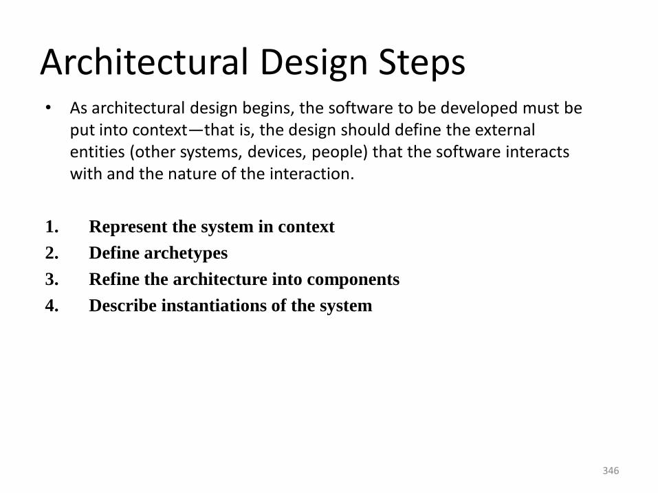
346
Architectural Design Steps• As architectural design begins, the software to be developed must be
put into context—that is, the design should define the external entities (other systems, devices, people) that the software interacts with and the nature of the interaction.
1. Represent the system in context
2. Define archetypes
3. Refine the architecture into components
4. Describe instantiations of the system
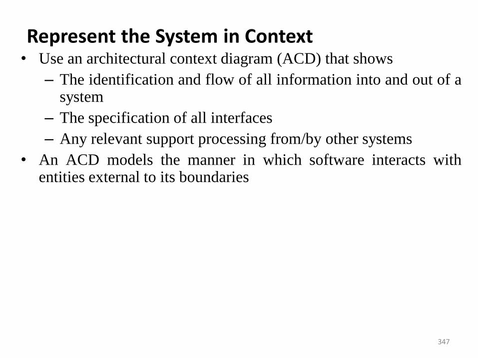
347
Represent the System in Context • Use an architectural context diagram (ACD) that shows
– The identification and flow of all information into and out of asystem
– The specification of all interfaces
– Any relevant support processing from/by other systems
• An ACD models the manner in which software interacts withentities external to its boundaries
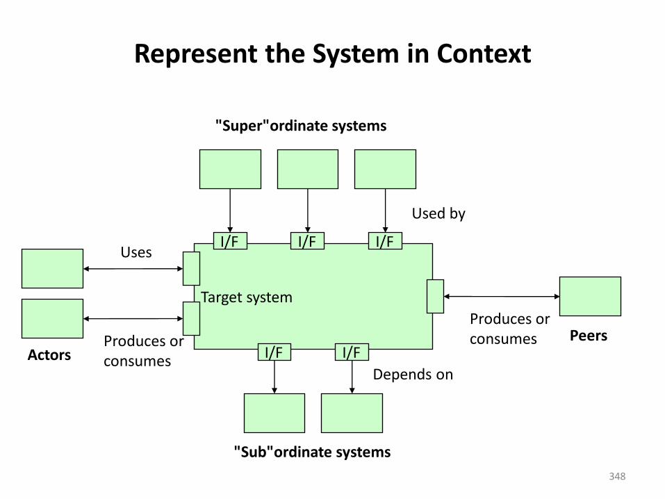
348
Represent the System in Context
Target system
I/F I/F
I/F I/F I/F
ActorsPeers
"Super"ordinate systems
"Sub"ordinate systems
Used by
Produces orconsumesProduces or
consumesDepends on
Uses
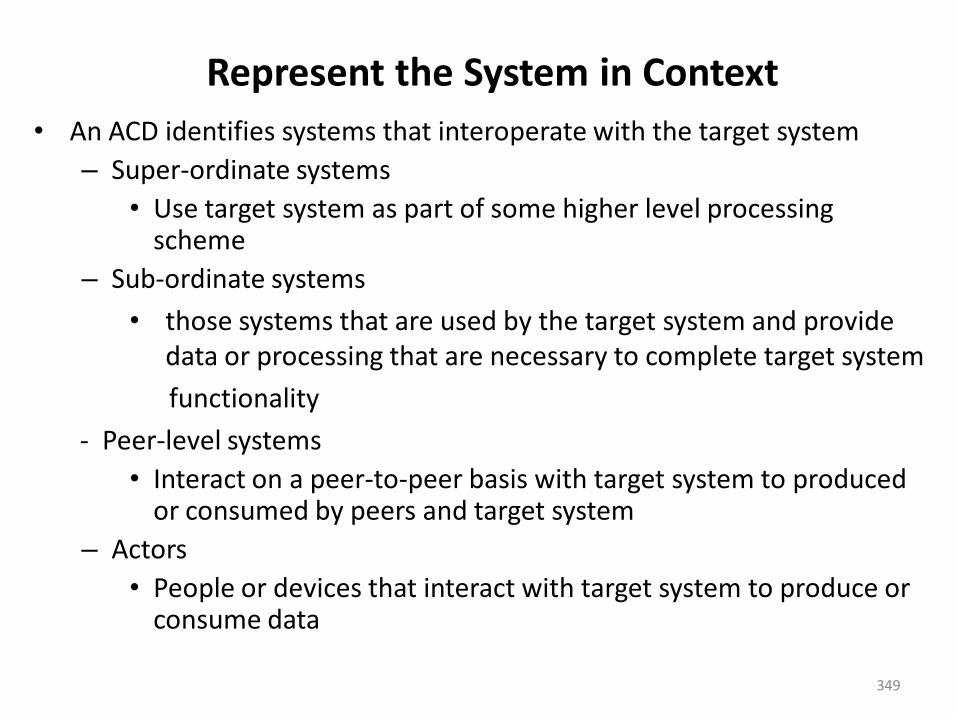
349
Represent the System in Context
• An ACD identifies systems that interoperate with the target system
– Super-ordinate systems
• Use target system as part of some higher level processing scheme
– Sub-ordinate systems
• those systems that are used by the target system and provide data or processing that are necessary to complete target system
functionality
- Peer-level systems
• Interact on a peer-to-peer basis with target system to produced or consumed by peers and target system
– Actors
• People or devices that interact with target system to produce or consume data
350
Define Archetypes
• Archetypes indicate the important abstractions within theproblem domain (i.e., they model information)
• An archetype is a class or pattern that represents a coreabstraction that is critical to the design of an architecturefor the target system
• Only a relatively small set of archetypes is required inorder to design even relatively complex systems
• The target system architecture is composed of thesearchetypes– They represent stable elements of the architecture– They may be instantiated in different ways based on
the behavior of the system– They can be derived from the analysis class model
• The archetypes and their relationships can be illustrated ina UML class diagram
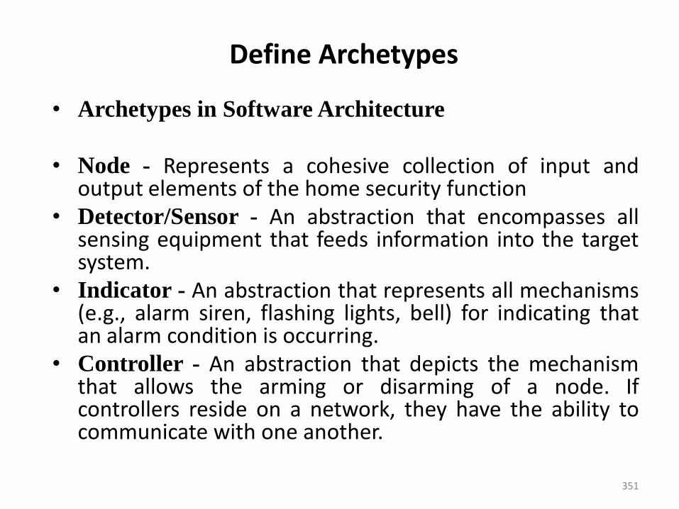
351
Define Archetypes
• Archetypes in Software Architecture
• Node - Represents a cohesive collection of input andoutput elements of the home security function
• Detector/Sensor - An abstraction that encompasses allsensing equipment that feeds information into the targetsystem.
• Indicator - An abstraction that represents all mechanisms(e.g., alarm siren, flashing lights, bell) for indicating thatan alarm condition is occurring.
• Controller - An abstraction that depicts the mechanismthat allows the arming or disarming of a node. Ifcontrollers reside on a network, they have the ability tocommunicate with one another.
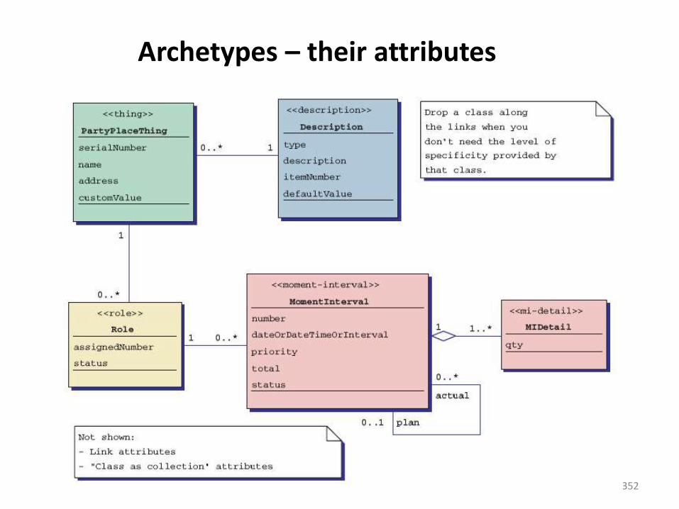
352
Archetypes – their attributes
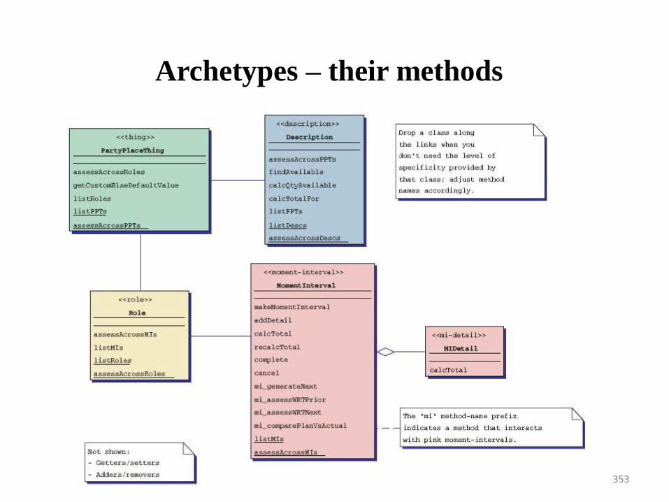
353
Archetypes – their methods
354
Refine the Architecture into Components
• Based on the archetypes, the architectural designer refines thesoftware architecture into components to illustrate the overallstructure and architectural style of the system
• These components are derived from various sources– The application domain provides application components, which
are the domain classes in the analysis model that represententities in the real world
– The infrastructure domain provides design components (i.e., design classes) that enable application components but have no business connection• Examples: memory management, communication, database, and
task management
• These components are derived from various sources– The interfaces in the ACD imply one or more specialized
components that process the data that flow across the interface
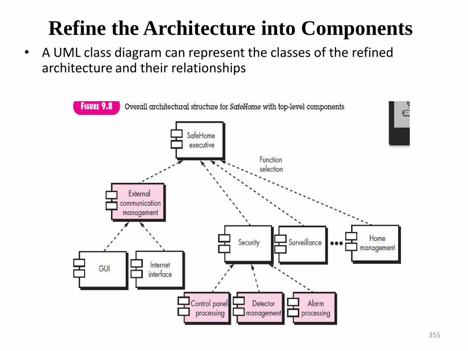
355
Refine the Architecture into Components• A UML class diagram can represent the classes of the refined
architecture and their relationships
356
Describe Instantiations of the System
• The architectural design that has been modeled to this point is still relatively high level.
• The context of the system has been represented, archetypes that indicate the important abstractions within the problem domain have been defined, the overall structure of the system is apparent, and the major software components have been identified.
• However, further refinement (recall that all design is iterative) is still necessary.
Assessing alternative architectural design• Design results in a number of architectural alternatives that are each assessed
to determine which is the most appropriate for the problem to be solved.
1. An Architecture Trade-Off Analysis Method
The Software Engineering Institute (SEI) has developed an architecture trade-off analysis method that establishes an iterative evaluation process forsoftware architectures. The design analysis activities that follow areperformed iteratively:
• Collect scenarios. A set of use cases is developed to represent the systemfrom the user’s point of view.
• Elicit requirements, constraints, and environment description. Thisinformation is determined as part of requirements engineering and is usedto be certain that all stakeholder concerns have been addressed.
• Describe the architectural styles/patterns that have been chosen toaddress the scenarios and requirements.
• Evaluate quality attributes by considering each attribute in isolation.
• Identify the sensitivity of quality attributes to various architecturalattributes for a specific architectural style.
• Critique candidate architectures (developed in step 3) using the sensitivityanalysis conducted
Assessing alternative architectural design2. Architectural Complexity
A useful technique for assessing the overall complexity of a proposedarchitecture is to consider dependencies between components within thearchitecture. These dependencies are driven by information/control flowwithin the system.
3. Architectural Description Languages
• Architectural description language (ADL) provides a semantics and syntaxfor describing a software architecture.
• ADL should provide the designer with the ability to decomposearchitectural components, compose individual components into largerarchitectural blocks, and represent interfaces (connection mechanisms)between components.
• Once descriptive, language based techniques for architectural design havebeen established, it is more likely that effective assessment methods forarchitectures will be established as the design evolves.
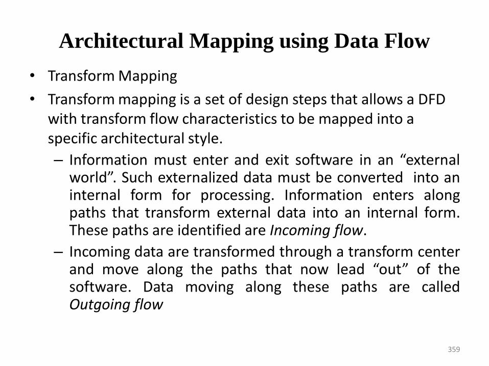
Architectural Mapping using Data Flow
• Transform Mapping
• Transform mapping is a set of design steps that allows a DFD with transform flow characteristics to be mapped into a specific architectural style.
– Information must enter and exit software in an “externalworld”. Such externalized data must be converted into aninternal form for processing. Information enters alongpaths that transform external data into an internal form.These paths are identified are Incoming flow.
– Incoming data are transformed through a transform centerand move along the paths that now lead “out” of thesoftware. Data moving along these paths are calledOutgoing flow
359
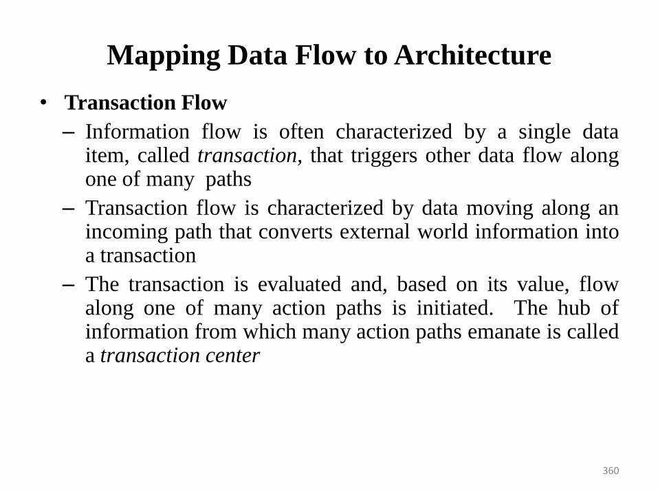
Mapping Data Flow to Architecture
• Transaction Flow
– Information flow is often characterized by a single dataitem, called transaction, that triggers other data flow alongone of many paths
– Transaction flow is characterized by data moving along anincoming path that converts external world information intoa transaction
– The transaction is evaluated and, based on its value, flowalong one of many action paths is initiated. The hub ofinformation from which many action paths emanate is calleda transaction center
360
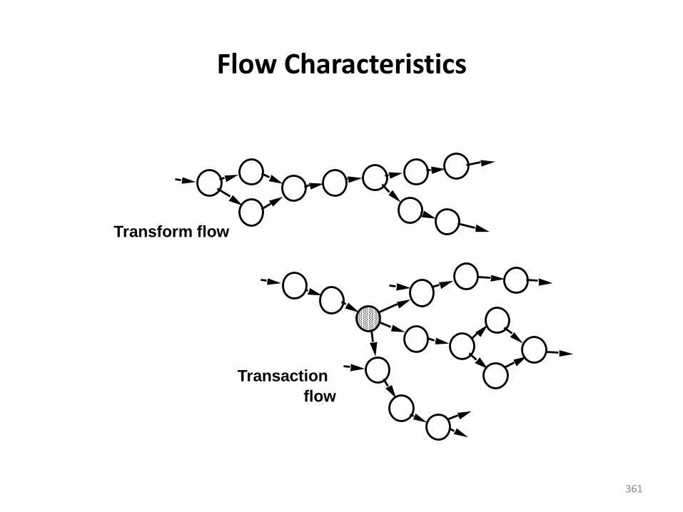
Flow Characteristics
Transform flow
Transaction
flow
361
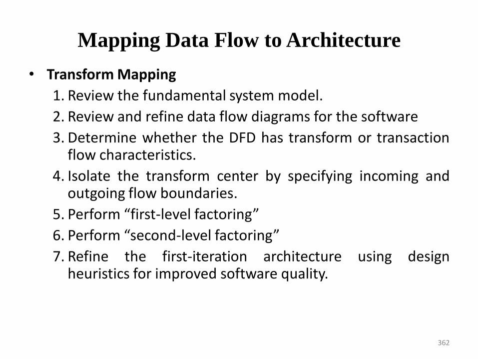
Mapping Data Flow to Architecture
• Transform Mapping
1. Review the fundamental system model.
2. Review and refine data flow diagrams for the software
3. Determine whether the DFD has transform or transactionflow characteristics.
4. Isolate the transform center by specifying incoming andoutgoing flow boundaries.
5. Perform “first-level factoring”
6. Perform “second-level factoring”
7. Refine the first-iteration architecture using designheuristics for improved software quality.
362
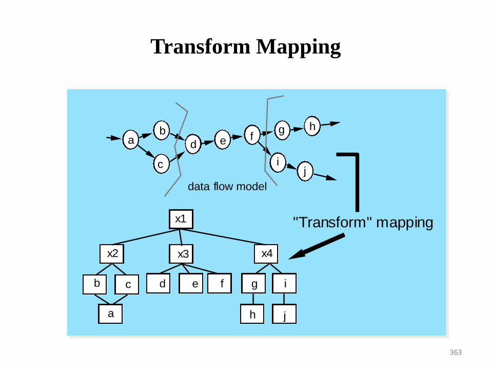
Transform Mapping
data flow model
"Transform" mapping
ab
c
d e fg h
ij
x1
x2 x3 x4
b c
a
d e f g i
h j
363
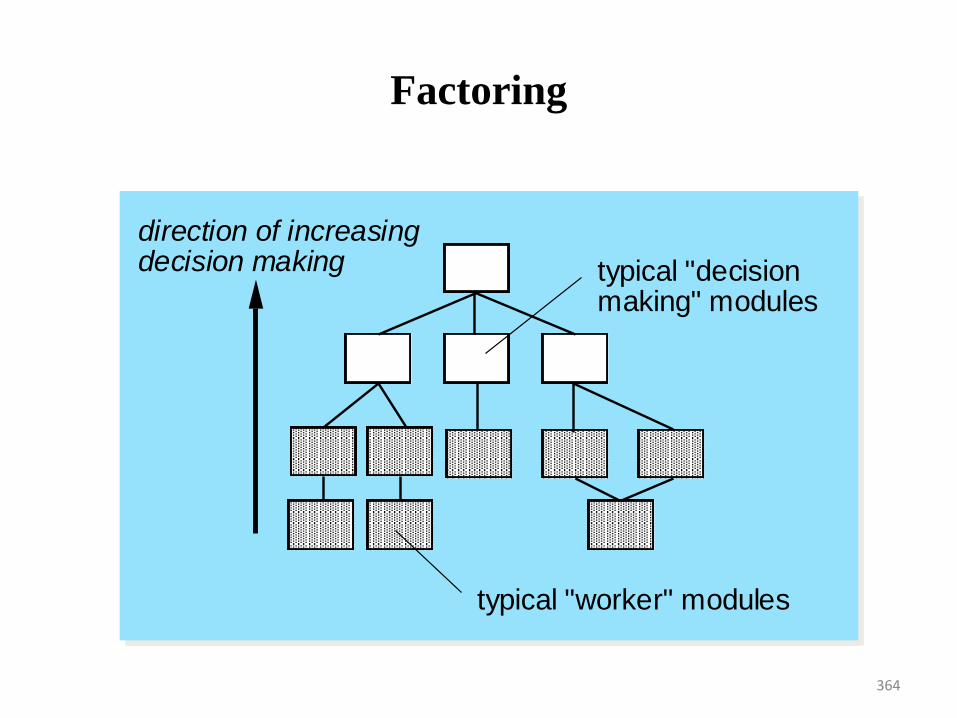
Factoring
typical "worker" modules
typical "decision making" modules
direction of increasing decision making
364
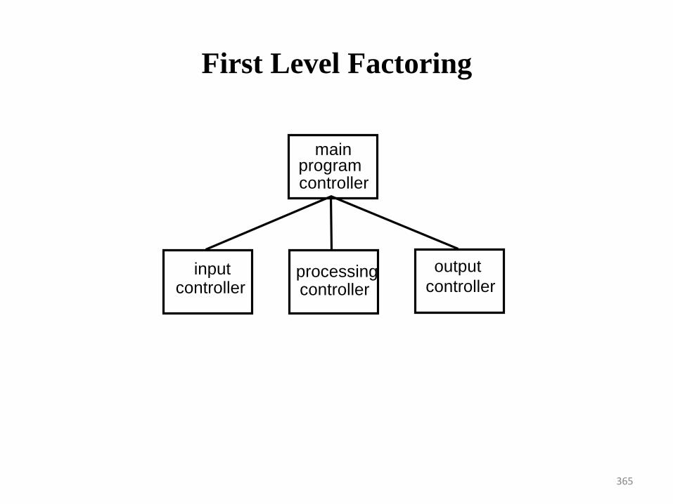
First Level Factoring
main programcontroller
inputcontroller
processingcontroller
output
controller
365
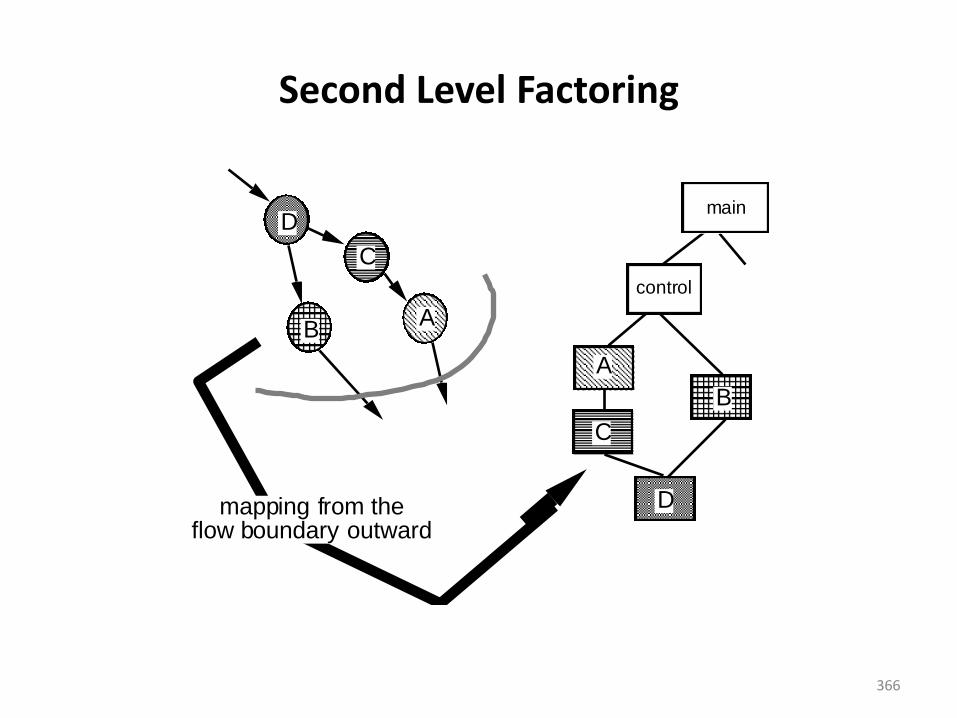
Second Level Factoring
D
C
BA
A
C
B
Dmapping from the flow boundary outward
main
control
366
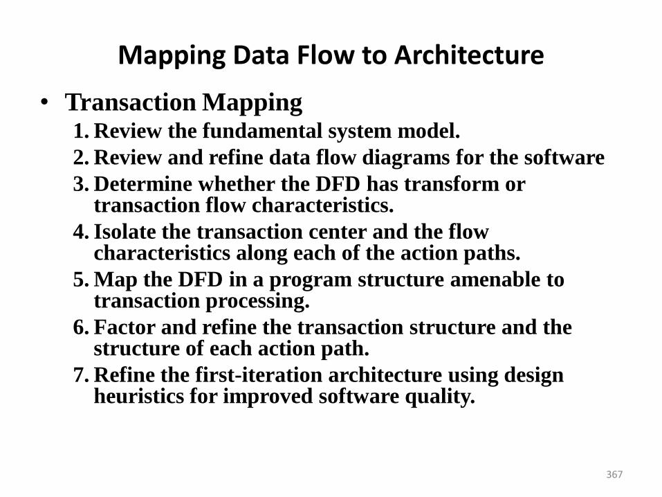
Mapping Data Flow to Architecture
• Transaction Mapping1. Review the fundamental system model.
2. Review and refine data flow diagrams for the software
3. Determine whether the DFD has transform or transaction flow characteristics.
4. Isolate the transaction center and the flow characteristics along each of the action paths.
5. Map the DFD in a program structure amenable to transaction processing.
6. Factor and refine the transaction structure and the structure of each action path.
7. Refine the first-iteration architecture using design heuristics for improved software quality.
367
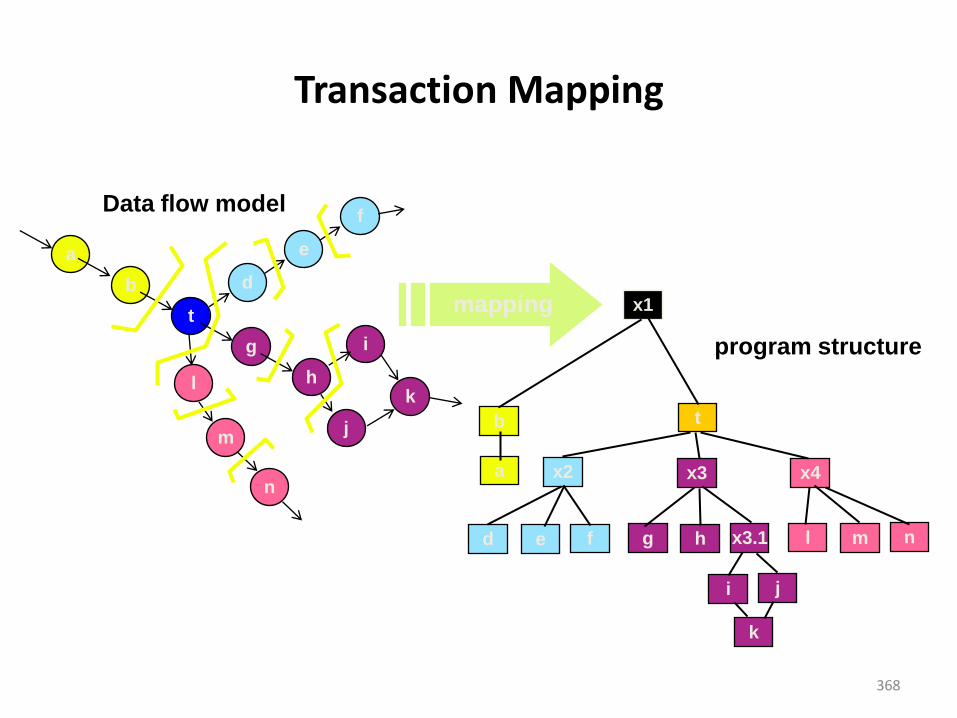
Transaction Mapping
a
b
t
g
h
d
e
f
i
k
j
l
m
n
Data flow model
x1
b
a
t
x2 x3 x4
d e f g h x3.1 l m n
i j
k
mapping
program structure
368
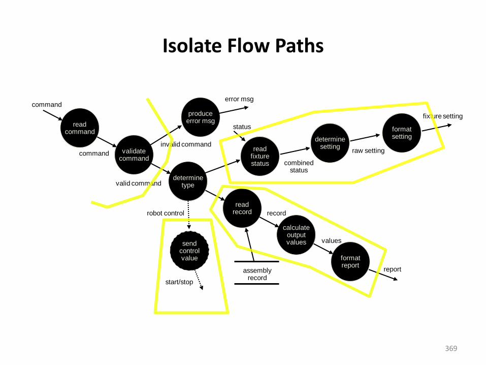
Isolate Flow Paths
readcommand
validatecommand
determinetype
readrecord
calculateoutputvalues
formatreport
produceerror msg
readfixturestatus
determinesetting
formatsetting
sendcontrolvalue
command
command
invalid command
error msg
status
combinedstatus
raw setting
fixture setting
robot control
start/stop
assemblyrecord
record
values
report
valid command
369
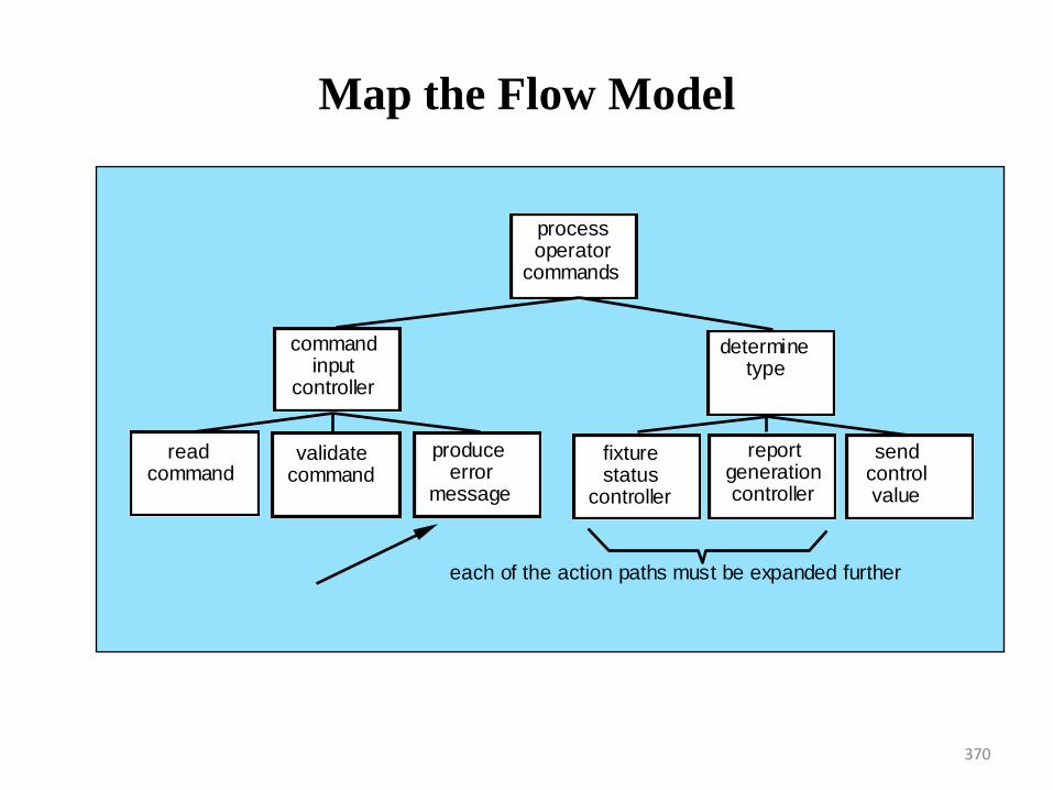
Map the Flow Model
process operator
commands
command input
controller
read command
validate command
produce error
message
determine type
fixture status
controller
report generation controller
send control value
each of the action paths must be expanded further
370
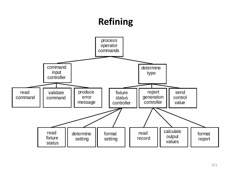
Refining
process operator
commands
command input
controller
read command
validate command
produce error
message
determine type
send control value
read fixture status
determine setting
format setting
read record
calculate output values
format report
fixture status
controller
report generation controller
371
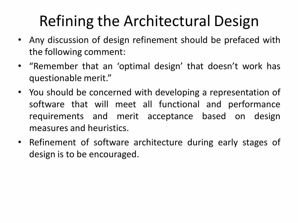
Refining the Architectural Design• Any discussion of design refinement should be prefaced with
the following comment:
• “Remember that an ‘optimal design’ that doesn’t work hasquestionable merit.”
• You should be concerned with developing a representation ofsoftware that will meet all functional and performancerequirements and merit acceptance based on designmeasures and heuristics.
• Refinement of software architecture during early stages ofdesign is to be encouraged.
373
Syllabus
• User interface design : Golden Rules, interface
analysis, interface design steps
• Modeling component-level design : Designing
class-based components, conducting
component level design, object constraint
language, designing conventional components
373
374
Performing User interface design
375
User interface design
• Background• Interface design focuses on the following
– The design of interfaces between software components
– The design of interfaces between the software and other nonhuman producers and consumers of information
– The design of the interface between a human and the computer
• Graphical user interfaces (GUIs) have helped to eliminate many of the most horrific interface problems
• However, some are still difficult to learn, hard to use, confusing, counterintuitive, unforgiving, and frustrating
• User interface analysis and design has to do with the study of people and how they relate to technology
376
The User Interface
• User interfaces creates an effective communication medium between a human and a computer
• Using a set of interface design principles, design identifies interface objects and actions and then creates a screen layout that forms the basis of a user interface prototype
• User interfaces should be designed to match the skills, experience and expectations of its anticipated users.
• System users often judge a system by its interface rather than its functionality.
• A poorly designed interface can cause a user to make catastrophic errors.
• Poor user interface design is the reason why so many software systems are never used.
377
The User Interface
• Easy to learn?
• Easy to use?
• Easy to Understand?
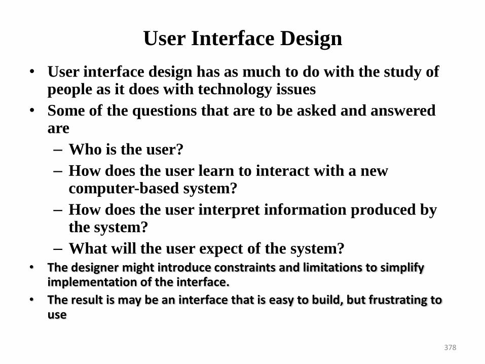
378
User Interface Design
• User interface design has as much to do with the study of people as it does with technology issues
• Some of the questions that are to be asked and answered are
– Who is the user?
– How does the user learn to interact with a new computer-based system?
– How does the user interpret information produced by the system?
– What will the user expect of the system?• The designer might introduce constraints and limitations to simplify
implementation of the interface.
• The result is may be an interface that is easy to build, but frustrating to use
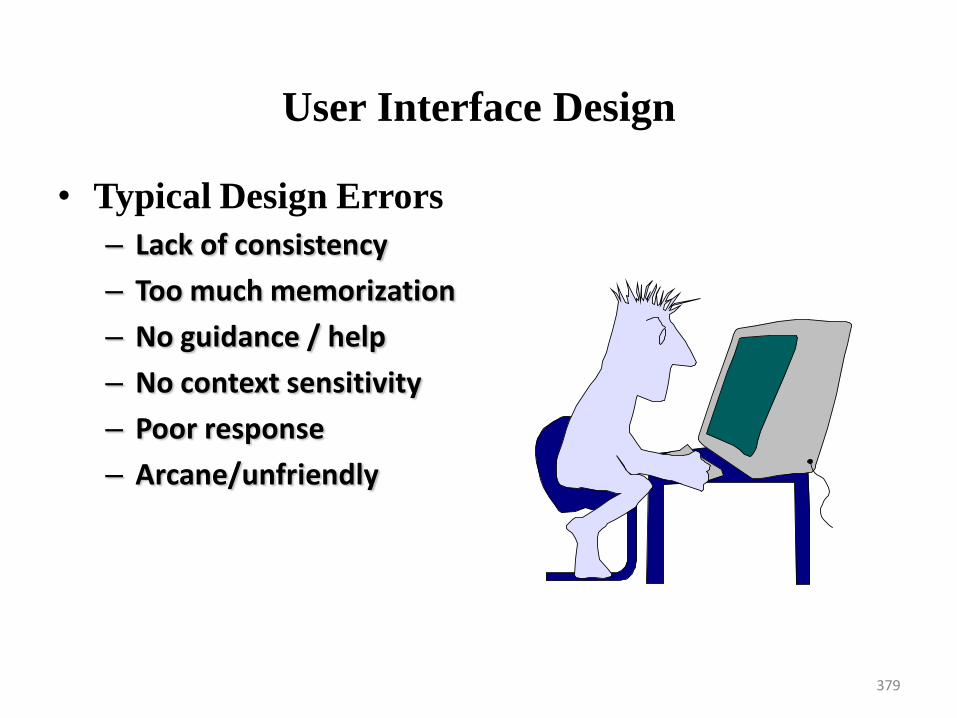
379
User Interface Design
• Typical Design Errors
– Lack of consistency
– Too much memorization
– No guidance / help
– No context sensitivity
– Poor response
– Arcane/unfriendly
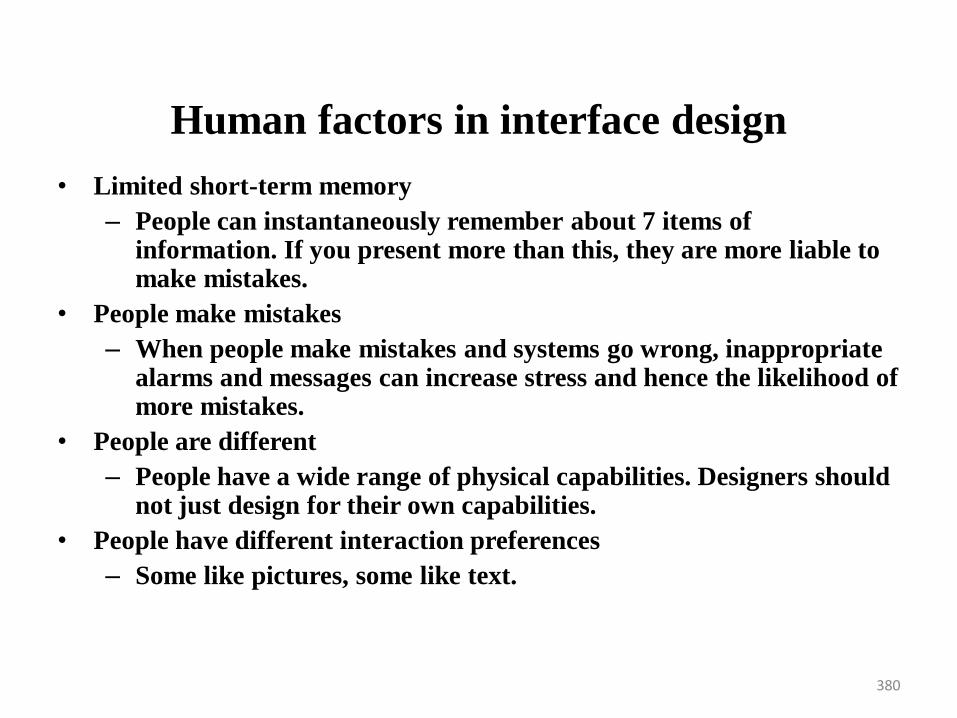
380
Human factors in interface design
• Limited short-term memory
– People can instantaneously remember about 7 items of information. If you present more than this, they are more liable to make mistakes.
• People make mistakes
– When people make mistakes and systems go wrong, inappropriate alarms and messages can increase stress and hence the likelihood of more mistakes.
• People are different
– People have a wide range of physical capabilities. Designers should not just design for their own capabilities.
• People have different interaction preferences
– Some like pictures, some like text.
381
User Interface Design
• Golden Rules
–Place the user in control
–Reduce the user’s memory load
–Make the interface consistent
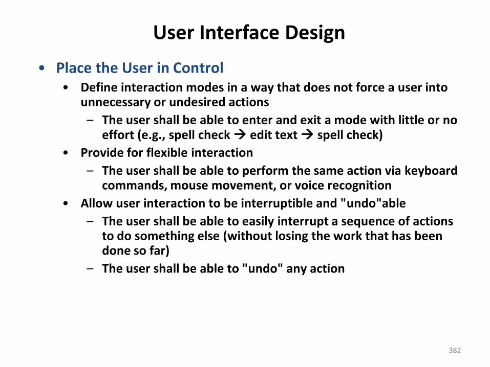
382
User Interface Design
• Place the User in Control• Define interaction modes in a way that does not force a user into
unnecessary or undesired actions
– The user shall be able to enter and exit a mode with little or no effort (e.g., spell check edit text spell check)
• Provide for flexible interaction
– The user shall be able to perform the same action via keyboard commands, mouse movement, or voice recognition
• Allow user interaction to be interruptible and "undo"able
– The user shall be able to easily interrupt a sequence of actions to do something else (without losing the work that has been done so far)
– The user shall be able to "undo" any action
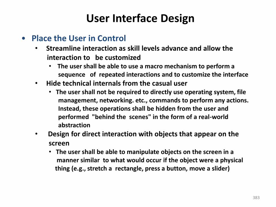
383
User Interface Design
• Place the User in Control• Streamline interaction as skill levels advance and allow the
interaction to be customized• The user shall be able to use a macro mechanism to perform a
sequence of repeated interactions and to customize the interface
• Hide technical internals from the casual user• The user shall not be required to directly use operating system, file
management, networking. etc., commands to perform any actions. Instead, these operations shall be hidden from the user and performed "behind the scenes" in the form of a real-worldabstraction
• Design for direct interaction with objects that appear on the screen• The user shall be able to manipulate objects on the screen in a
manner similar to what would occur if the object were a physical thing (e.g., stretch a rectangle, press a button, move a slider)
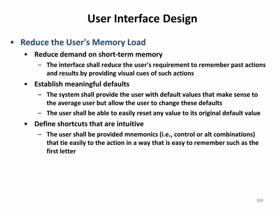
384
User Interface Design
• Reduce the User's Memory Load• Reduce demand on short-term memory
– The interface shall reduce the user's requirement to remember past actions and results by providing visual cues of such actions
• Establish meaningful defaults
– The system shall provide the user with default values that make sense to the average user but allow the user to change these defaults
– The user shall be able to easily reset any value to its original default value
• Define shortcuts that are intuitive
– The user shall be provided mnemonics (i.e., control or alt combinations) that tie easily to the action in a way that is easy to remember such as the first letter
385
User Interface Design
• Reduce the User's Memory Load• The visual layout of the interface should be based on a real world
metaphor • The screen layout of the user interface shall contain well-
understood visual cues that the user can relate to real-world actions
• Disclose information in a progressive fashion• When interacting with a task, an object or some behavior, the
interface shall be organized hierarchically by moving the user progressively in a step-wise fashion from an abstract concept to a concrete action (e.g., text format options format dialog box)
The more a user has to remember, the more error-prone interaction with the system will be
386
User Interface Design
• Make the Interface Consistent• The interface should present and acquire information in a consistent
fashion
– All visual information shall be organized according to a design standard that is maintained throughout all screen displays
– Input mechanisms shall be constrained to a limited set that is used consistently throughout the application
– Mechanisms for navigating from task to task shall be consistently defined and implemented
• Allow the user to put the current task into a meaningful context
– The interface shall provide indicators (e.g., window titles, consistent color coding) that enable the user to know the context of the work at hand
– The user shall be able to determine where he has come from and what alternatives exist for a transition to a new task
387
User Interface Design
• Make the Interface Consistent
• Maintain consistency across a family of applications• A set of applications performing complimentary functionality
shall all implement the same design rules so that consistency is maintained for all interaction
• If past interactive models have created user expectations, do not make changes unless there is a compelling reason to do so• Once a particular interactive sequence has become a de facto standard (e.g., alt-S to save a file), the application shall continue this expectation in every part of its functionality
388
User Interface Design Models
• Four different models come into play when a user interface is analyzed and designed
– User profile model – Established by a human engineer or software engineer
– Design model – Created by a software engineer
– Implementation model – Created by the software implementers
– User's mental model – Developed by the user when interacting with the application
• The role of the interface designer is to reconcile these differences and derive a consistent representation of the interface
389
User Profile Model
• Establishes the profile of the end-users of the system
– Based on age, gender, physical abilities, education, cultural or ethnic background, motivation, goals, and personality
• Considers syntactic knowledge of the user
– The mechanics of interaction that are required to use the interface effectively
• Considers semantic knowledge of the user
– The underlying sense of the application; an understanding of the functions that are performed, the meaning of input and output, and the objectives of the system
390
User Profile Model
• Categorizes users as
– Novices
• No syntactic knowledge of the system, little semantic knowledge of the application, only general computer usage
– Knowledgeable, intermittent users
• Reasonable semantic knowledge of the system, low recall of syntactic information to use the interface
– Knowledgeable, frequent users
• Good semantic and syntactic knowledge (i.e., power user), look for shortcuts and abbreviated modes of operation
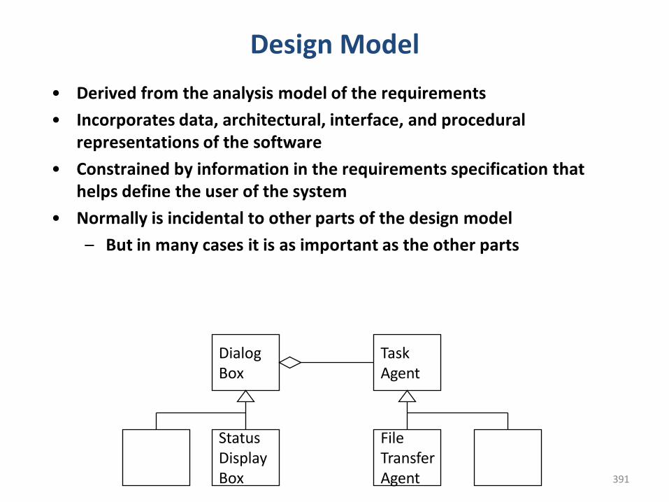
391
Design Model
• Derived from the analysis model of the requirements
• Incorporates data, architectural, interface, and procedural representations of the software
• Constrained by information in the requirements specification that helps define the user of the system
• Normally is incidental to other parts of the design model
– But in many cases it is as important as the other parts
TaskAgent
StatusDisplayBox
DialogBox
File TransferAgent
392
Implementation Model
• Consists of the look and feel of the interface combined with all supporting information (books, videos, help files) that describe system syntax and semantics
• Strives to agree with the user's mental model; users then feel comfortable with the software and use it effectively
• Serves as a translation of the design model by providing a realization of the information contained in the user profile model and the user’s mental model
393
User's Mental Model
• Often called the user's system perception
• Consists of the image of the system that users carry in their heads
• Accuracy of the description depends upon the user’s profile and overall familiarity with the software in the application domain
394
User Interface Development
• User interface development follows a spiral process – Interface analysis (user, task, and environment analysis)
• Focuses on the profile of the users who will interact with the system
• Concentrates on users, tasks, content and work environment • Studies different models of system function (as perceived from the
outside)• Delineates the human- and computer-oriented tasks that are
required to achieve system function– Interface design
• Defines a set of interface objects and actions (and their screen representations) that enable a user to perform all defined tasks in a manner that meets every usability goal defined for the system
395
User Interface Development
• User interface development follows a spiral process – Interface construction
• Begins with a prototype that enables usage scenarios to be evaluated
• Continues with development tools to complete the construction– Interface validation, focuses on
• The ability of the interface to implement every user task correctly, to accommodate all task variations, and to achieve all general user requirements
• The degree to which the interface is easy to use and easy to learn• The users' acceptance of the interface as a useful tool in their
work
396
User Interface Analysis
• Elements of the User Interface
– To perform user interface analysis, the practitioner needs to study
and understand four elements
• The users who will interact with the system through the
interface
• The tasks that end users must perform to do their work
• The content that is presented as part of the interface
• The work environment in which these tasks will be conducted
397
User Interface Analysis
• User Analysis
– The analyst strives to get the end user's mental model and the design model to converge by understanding
• The users themselves
• How these people use the system
– Information can be obtained from
• User interviews with the end users
• Sales input from the sales people who interact with customers and users on a regular basis
• Marketing input based on a market analysis to understand how different population segments might use the software
• Support input from the support staff who are aware of what works and what doesn't, what users like and dislike, what features generate questions, and what features are easy to use
– A set of questions should be answered during user analysis
398
User Interface Analysis
• User Analysis Questions
1) Are the users trained professionals, technicians, clerical or manufacturing workers?
2) What level of formal education does the average user have?
3) Are the users capable of learning on their own from written materials or have they expressed a desire for classroom training?
4) Are the users expert typists or are they keyboard phobic?
5) What is the age range of the user community?
6) Will the users be represented predominately by one gender?
7) How are users compensated for the work they perform or are they volunteers?
399
User Interface Analysis
• User Analysis Questions
8. Do users work normal office hours, or do they work whenever the job is required?
9. Is the software to be an integral part of the work users do, or will it be used only occasionally?
10. What is the primary spoken language among users?
11. What are the consequences if a user makes a mistake using the system?
12. Are users experts in the subject matter that is addressed by the system?
13. Do users want to know about the technology that sits behind the interface?
400
User Interface Analysis
• Task Analysis and Modeling
– Task analysis strives to know and understand
• The work the user performs in specific circumstances
• The tasks and subtasks that will be performed as the user does the work
• The specific problem domain objects that the user manipulates as work is performed
• The sequence of work tasks (i.e., the workflow)
• The hierarchy of tasks
– Use cases
• Show how an end user performs some specific work-related task
• Enable the software engineer to extract tasks, objects, and overall workflow of the interaction
• Helps the software engineer to identify additional helpful features
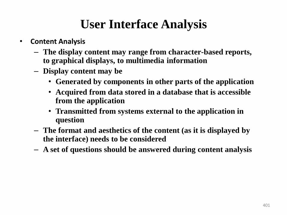
401
User Interface Analysis
• Content Analysis
– The display content may range from character-based reports, to graphical displays, to multimedia information
– Display content may be
• Generated by components in other parts of the application
• Acquired from data stored in a database that is accessible from the application
• Transmitted from systems external to the application in question
– The format and aesthetics of the content (as it is displayed by the interface) needs to be considered
– A set of questions should be answered during content analysis
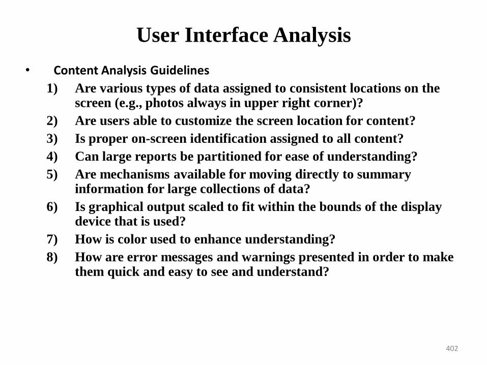
402
User Interface Analysis
• Content Analysis Guidelines
1) Are various types of data assigned to consistent locations on the screen (e.g., photos always in upper right corner)?
2) Are users able to customize the screen location for content?
3) Is proper on-screen identification assigned to all content?
4) Can large reports be partitioned for ease of understanding?
5) Are mechanisms available for moving directly to summary information for large collections of data?
6) Is graphical output scaled to fit within the bounds of the display device that is used?
7) How is color used to enhance understanding?
8) How are error messages and warnings presented in order to make them quick and easy to see and understand?
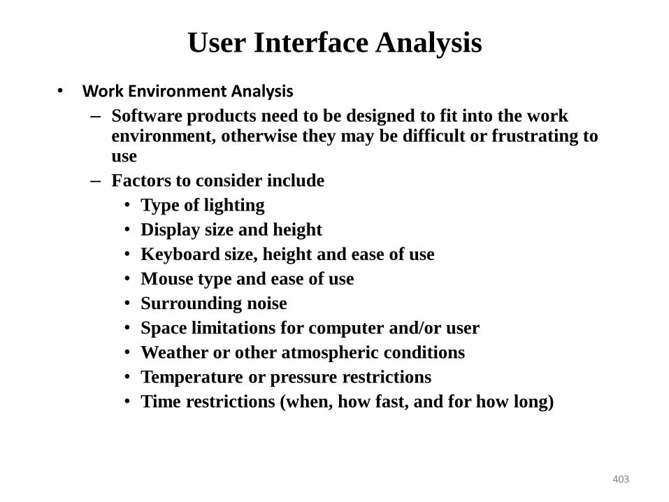
403
User Interface Analysis
• Work Environment Analysis
– Software products need to be designed to fit into the work environment, otherwise they may be difficult or frustrating to use
– Factors to consider include
• Type of lighting
• Display size and height
• Keyboard size, height and ease of use
• Mouse type and ease of use
• Surrounding noise
• Space limitations for computer and/or user
• Weather or other atmospheric conditions
• Temperature or pressure restrictions
• Time restrictions (when, how fast, and for how long)
Interface Design Steps
1. Applying Interface Design Steps
2. User Interface Design Patterns
3. Design Issues
405
User Interface Design• User interface design is an iterative process, where each iteration
elaborate and refines the information developed in the preceding steps
• General steps for user interface design
1) Using information developed during user interface analysis, define user interface objects and actions (operations)
2) Define events (user actions) that will cause the state of the user interface to change; model this behavior
3) Depict each interface state as it will actually look to the end user
4) Indicate how the user interprets the state of the system from information provided through the interface
• During all of these steps, the designer must
– Always follow the three golden rules of user interfaces
– Model how the interface will be implemented
– Consider the computing environment (e.g., display technology, operating system, development tools) that will be used
406
User Interface Design
• Applying Interface Design Steps • Interface objects and actions are obtained from a grammatical
parse of the use cases and the software problem statement
– Interface objects are categorized into types: source, target, and application
• A source object is dragged and dropped into a target object such as to create a hardcopy of a report
• An application object represents application-specific data that are not directly manipulated as part of screen interaction such as a list
– After identifying objects and their actions, an interface designer performs screen layout which involves
• Graphical design and placement of icons
• Definition of descriptive screen text
• Specification and titling for windows
• Definition of major and minor menu items
• Specification of a real-world metaphor to follow
User Interface Design• User Interface Design Patterns• Graphical user interfaces have become so common that a wide variety of
user interface design patterns has emerged.
• A design pattern is an abstraction that prescribes a design solution to a
specific, well-bounded design problem.
• As an example of a commonly encountered interface design problem,
consider a situation in which a user must enter one or more calendar dates,
sometimes months in advance. There are many possible solutions to this
simple problem, and a number of different patterns that might be proposed.
Laakso [Laa00] suggests a pattern called CalendarStrip that produces a
continuous, scrollable calendar in which the current date is highlighted and
future dates may be selected by picking them from the calendar. The
calendar metaphor is well known to every user and provides an effective
mechanism for placing a future date in context.
408
User Interface Design
• Design Issues
• Four common design issues usually surface in any user interface
– System response time
• System response time is the primary complaint for many interactive applications.
• System response time is measured from the point at which the user performs some control action (e.g., hits the return key or clicks a mouse) until the software responds with desired output or action.
• System response time has two important characteristics: length and variability. If system response is too long, user frustration and stress are inevitable. Variability refers to the deviation from average response time, and in many ways, it is the most important response time characteristic.
User Interface Design– Help facilities
• Almost every user of an interactive, computer-based systemrequires help now and then.
• Modern software provides online help facilities that enable a userto get a question answered or resolve a problem without leavingthe interface.
• A number of design issues must be addressed when a help facilityis considered:
• When is it available, how is it accessed, how is it represented tothe user, how is it structured, what happens when help is exited
– Error handling
• Error messages and warnings are ―bad news‖ delivered to usersof interactive systems when something has gone awry. At theirworst, error messages and warnings impart useless or misleadinginformation and serve only to increase user frustration.
410
User Interface Design
• In general, every error message or warning produced by an interactive system should have the following characteristics:
– The message should describe the problem in plain language that a typical user can understand
– The message should provide constructive advice for recovering from the error
– The message should indicate any negative consequences of the error (e.g., potentially corrupted data files) so that the user can check to ensure that they have not occurred (or correct them if they have)
– The message should be accompanied by an audible or visual cuesuch as a beep, momentary flashing, or a special error color
– The message should be non-judgmental i.e The message should never place blame on the user
An effective error message philosophy can do much to improve the quality of an interactive system and will significantly reduce user
frustration when problems do occur
411
User Interface Design
– Menu and command labeling
• The typed command was once the most common mode of interactionbetween user and system software and was commonly used forapplications of every type.
• Today, the use of window-oriented, point-and pick interfaces hasreduced reliance on typed commands, but some power-users continueto prefer a command-oriented mode of interaction.
• A number of design issues arise when typed commands or menu labelsare provided as a mode of interaction:– Will every menu option have a corresponding command?– What form will a command take? A control sequence? A function
key? A typed word?– How difficult will it be to learn and remember the commands?– What can be done if a command is forgotten?– Can commands be customized or abbreviated by the user?– Are menu labels self-explanatory within the context of the
interface?– Are submenus consistent with the function implied by a master
menu item?
COMPONENT- LEVEL DESIGN• What Is a Component?
• An Object-Oriented View
• The Traditional View
• A Process-Related View
• Designing Class-Based Components
• Basic Design Principles
• Component-Level Design Guidelines
• Cohesion
• Coupling
• Designing Traditional Components
• Graphical Design Notation
• Tabular Design Notation
• Program Design Language
413
Component Definitions
• What Is a Component?
• An Object-Oriented View
• The Traditional View
• A Process-Related View
• A software component is a software element that conforms to acomponent model and can be independently deployed and composedwithout modification according to a composition standard.
– A software component is a unit of composition with contractuallyspecified interfaces and explicit context dependencies only. A softwarecomponent can be deployed independently and is subject tocomposition by third-parties.
– A modular, deployable, and replaceable part of a system thatencapsulates implementation and exposes a set of interfaces
414
Component-level Design
• A complete set of software components is defined during architectural design
• But the internal data structures and processing details of each component are not represented at a level of abstraction that is close to code
• Component-level design defines the data structures, algorithms, interface characteristics, and communication mechanisms allocated to each component
415
Component Views
• An Object-Oriented View
– A component is a set of collaborating classes.– Each class within a component is fully elaborated to include
all attributes and operations that are relevant to its implementation
– As part of the design elaboration, all interfaces that enable the classes to communicate and collaborate with other design classes must also be defined
– Begins with analysis model and elaborates analysis classes (for components that relate to the problem domain) and infrastructure classes ( for components that provide support services for the problem domain)
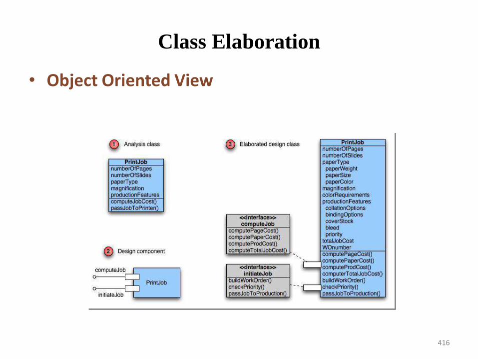
416
Class Elaboration
• Object Oriented View
417
Component Views
• The Traditional View – A component is a functional element ofa program that incorporates processing logic, the internal datastructures required to implement the processing logic, and aninterface that enables the component to be invoked and datato be passed to it.
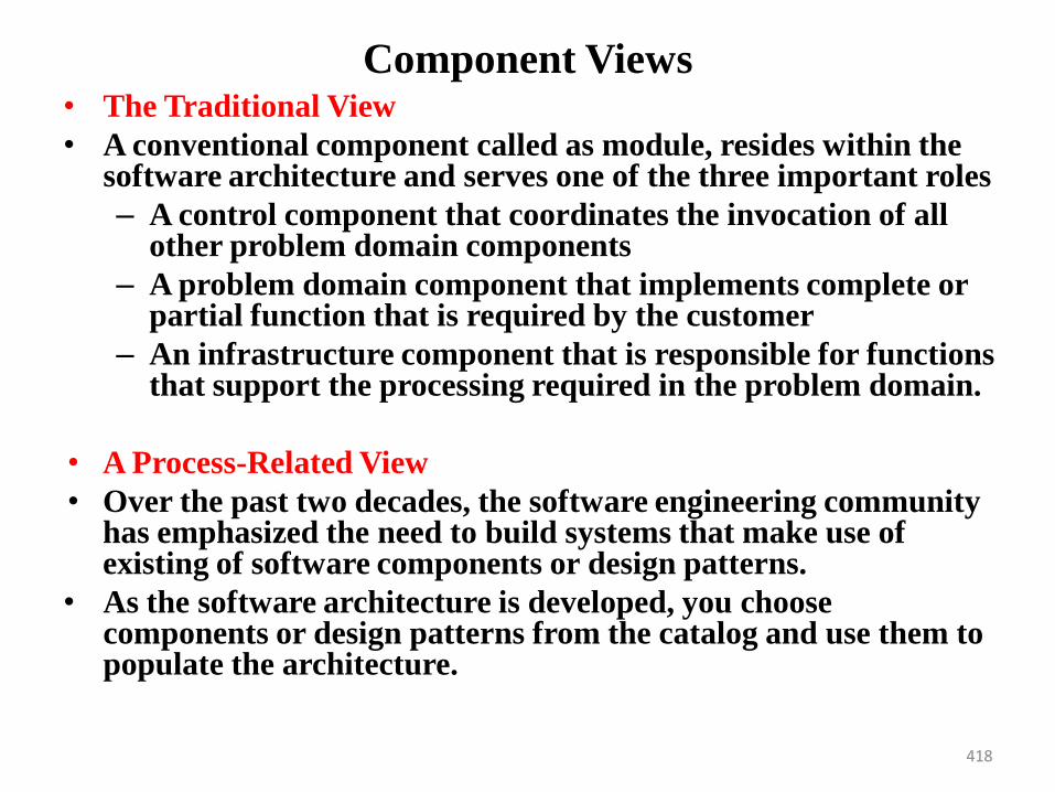
418
Component Views• The Traditional View
• A conventional component called as module, resides within the software architecture and serves one of the three important roles
– A control component that coordinates the invocation of all other problem domain components
– A problem domain component that implements complete or partial function that is required by the customer
– An infrastructure component that is responsible for functions that support the processing required in the problem domain.
• A Process-Related View
• Over the past two decades, the software engineering community has emphasized the need to build systems that make use of existing of software components or design patterns.
• As the software architecture is developed, you choose components or design patterns from the catalog and use them to populate the architecture.
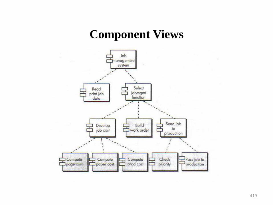
419
Component Views
420
Designing Class Based Components
Designing Class Based Components
1. Basic Design Principles
2. Component-Level Design Guidelines
3. Cohesion
4. Coupling
• Component-level design focuses on the elaboration of analysis classes (problem domain specific classes) and definition and refinement of infrastructure classes
• Purpose of using design principles is to create designs that are more amenable to change and to reduce propagation of side effects when changes do occur
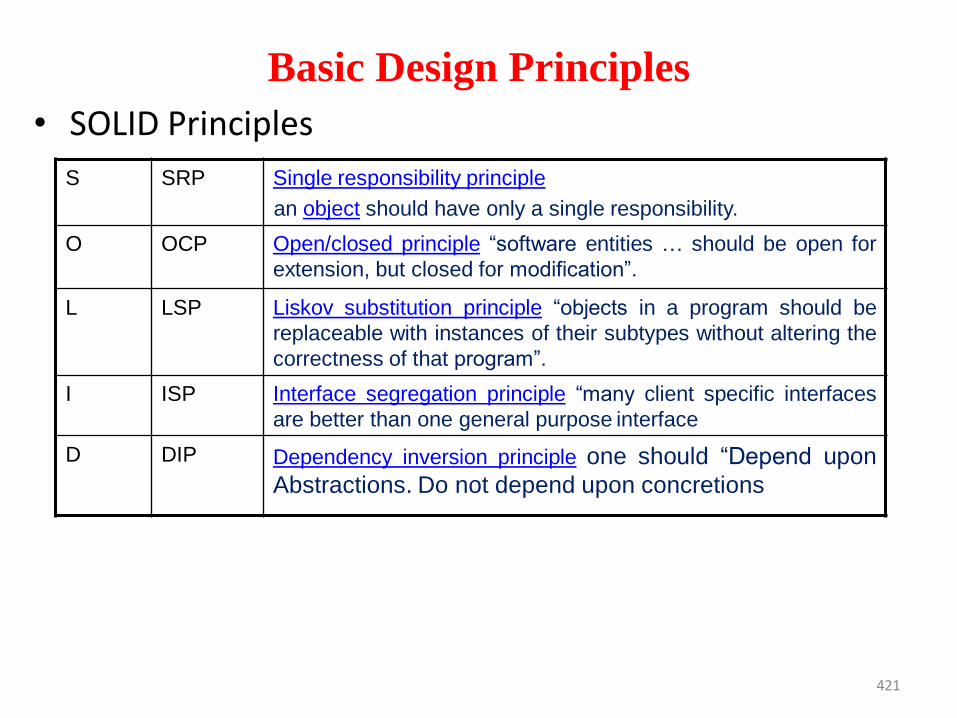
421
Basic Design Principles
• SOLID Principles
S SRP Single responsibility principle
an object should have only a single responsibility.
O OCP Open/closed principle “software entities … should be open for
extension, but closed for modification”.
L LSP Liskov substitution principle “objects in a program should be
replaceable with instances of their subtypes without altering the
correctness of that program”.
I ISP Interface segregation principle “many client specific interfaces
are better than one general purpose interface
D DIP Dependency inversion principle one should “Depend upon
Abstractions. Do not depend upon concretions
422
Basic Design Principles
• Single Responsibility Principle
• Open-Closed Principle
• Liskov Substitution Principle
• Dependency inversion Principle
• Interface segregation Principle

423
Single Responsibility Principle
• Single responsibility principle states that every classshould have a single responsibility, and thatresponsibility should be entirely encapsulated by theclass. All its services should be narrowly aligned withthat responsibility.
• Classes that keeps track of a lot of information andhave several responsibilities.
• One code change will most likely affect other parts ofthe class and therefore indirectly all other classesthat uses it.
• That in turn leads to an even bigger maintenancemess since no one dares to do any changes otherthan adding new functionality to it.
424
Single Responsibility Principle
• Just because you can, does not mean should
425
Open-Closed Principle
• A module should be open for extension but closed formodification
• The designer should specify the component in a waythat it allows to be extended (within the functionaldomain that it addresses) without the need to makeinternal modifications ( code or logic level) to thecomponent
• Abstractions are created that serve as a bufferbetween the functionality that is likely to beextended and the design class
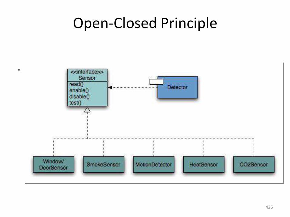
426
Open-Closed Principle
.
427
Open-Closed Principle
• Open chest surgery is not needed when putting on a coat.
428
The Liskov Substitution Principle (LSP). • “Subclasses should be substitutable for their base
classes”.• A component that uses a base class should continue
to function properly if a class derived from the baseclass is passed to the component instead
• Any class derived from the base class must honourany implied contract between the base class andthe components that uses it
• A contract is a precondition that must be truebefore the component uses a base class and a postcondition that should be true after the componentuses the base class
• When a designer creates derived classes, they mustalso conform to pre and post conditions
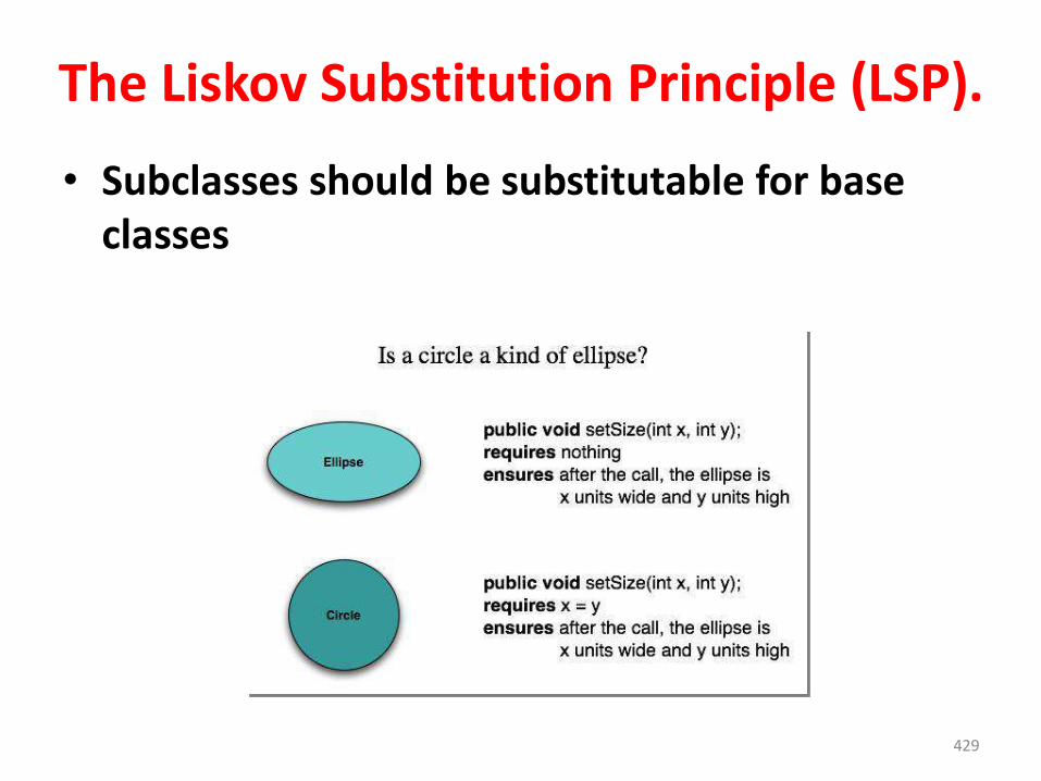
429
The Liskov Substitution Principle (LSP).
• Subclasses should be substitutable for base classes
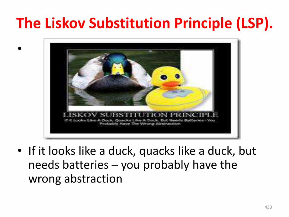
430
The Liskov Substitution Principle (LSP).
•
• If it looks like a duck, quacks like a duck, but needs batteries – you probably have the wrong abstraction
431
The Interface Segregation Principle (ISP).
• ―Many client-specific interfaces are better than one
general purpose interface‖
• Many instances in which multiple client components use
the operations provided by a server class.
• ISP suggests that you should create a specialized interface
to serve each major category of clients.
• Only those operations that are relevant to a particular
category of clients should be specified in the interface for
that client.
• If multiple clients require the same operations, it should be
specified in each of the specialized interfaces.
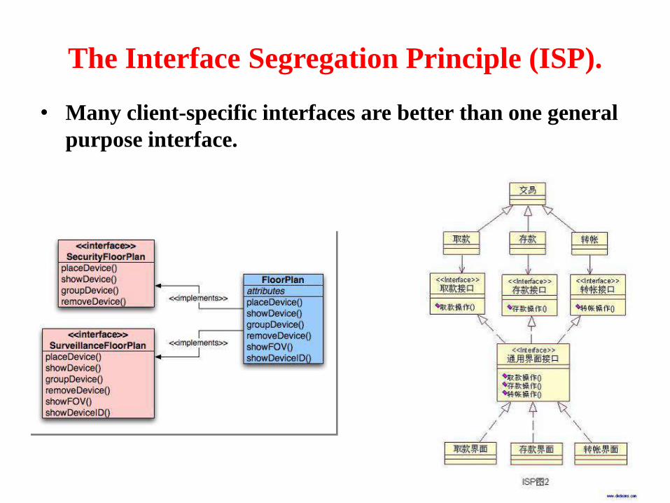
432
The Interface Segregation Principle (ISP).
• Many client-specific interfaces are better than one general
purpose interface.
433
The Interface Segregation Principle (ISP).
• You want me to plug this in, where?

434
Dependency Inversion Principle (DIP)
• “Depend on abstractions. Do not depend onconcretions”
• High level modules should not depend uponlow level modules. Both should depend uponabstractions.
• Abstractions should not depend upon details.Details should depend upon abstractions
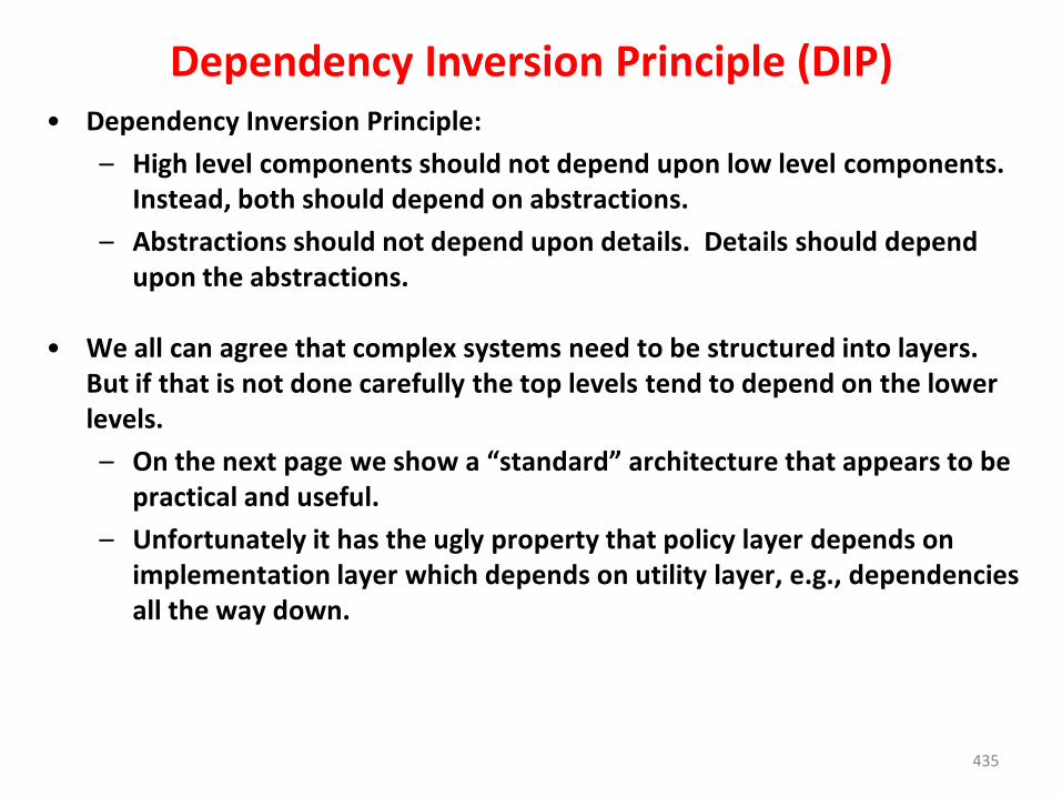
435
Dependency Inversion Principle (DIP)• Dependency Inversion Principle:
– High level components should not depend upon low level components. Instead, both should depend on abstractions.
– Abstractions should not depend upon details. Details should depend upon the abstractions.
• We all can agree that complex systems need to be structured into layers. But if that is not done carefully the top levels tend to depend on the lower levels.
– On the next page we show a “standard” architecture that appears to be practical and useful.
– Unfortunately it has the ugly property that policy layer depends on implementation layer which depends on utility layer, e.g., dependencies all the way down.
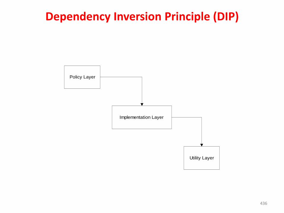
436
Dependency Inversion Principle (DIP)
Policy Layer
Implementation Layer
Utility Layer
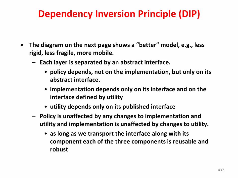
437
Dependency Inversion Principle (DIP)
• The diagram on the next page shows a “better” model, e.g., less rigid, less fragile, more mobile.
– Each layer is separated by an abstract interface.
• policy depends, not on the implementation, but only on its abstract interface.
• implementation depends only on its interface and on the interface defined by utility
• utility depends only on its published interface
– Policy is unaffected by any changes to implementation and utility and implementation is unaffected by changes to utility.
• as long as we transport the interface along with its component each of the three components is reusable and robust
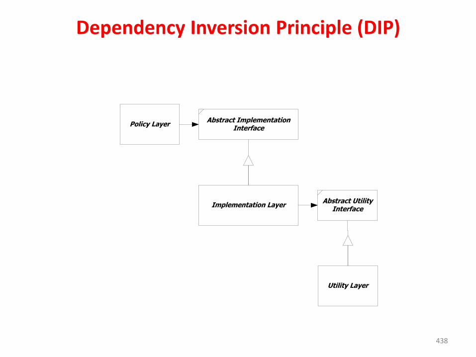
438
Dependency Inversion Principle (DIP)
Policy Layer
Implementation Layer
Utility Layer
Abstract ImplementationInterface
Abstract UtilityInterface
439
Dependency Inversion Principle (DIP)
•
• Would you solder a lamp directly to the electrical wiring in a wall?
Component-Level Design Guidelines• In addition to the principles discussed, a set of pragmatic design
guidelines can be applied as component-level design proceeds.
• These guidelines apply to components, their interfaces, and thedependencies and inheritance and inheritance characteristics that
have an impact on the resultant design.
• Components: Naming conventions should be established forcomponents that are specified as part of the architectural modeland then refined and elaborated as part of the component-levelmodel.
• Architectural component names should be drawn from the problemdomain and should have meaning to all stakeholders who view thearchitectural model.
• For example, the class name FloorPlan is meaningful to everyonereading it regardless of technical background.
Component-Level Design Guidelines• Interfaces: Interfaces provide important information about communication
and collaboration
• Ambler recommends that
(1) lollipop representation of an interface should be used in lieu of the more formal UML box and dashed arrow approach, when diagrams grow complex;
(2) for consistency, interfaces should flow from the left-hand side of the component box;
(3)only those interfaces that are relevant to the component under consideration should be shown, even if other interfaces are available.
• Dependencies and Inheritance:
• For improved readability, it is a good idea to model dependencies from left to right and inheritance from bottom (derived classes) to top (base classes).
442
Cohesion
• The “single-mindedness” of a component.
• Cohesion implies that a single component or class encapsulates only attributes and operations that are closely related to one another and to the class or component itself.
• Types of cohesion
– Functional
– Layer
– Communicational
443
Functional Cohesion• A form of cohesion in which modules together perform a
function (a computation) that returns a result and has no side effects) are kept together, and everything else is kept out
• Has advantages– It is easier to understand a module when you know all it
does is generate one specific output and has no side effects– It is easier to replace a functionally cohesive module with
another that performs the same computation– Functionally cohesive module is much more likely to be
reusable
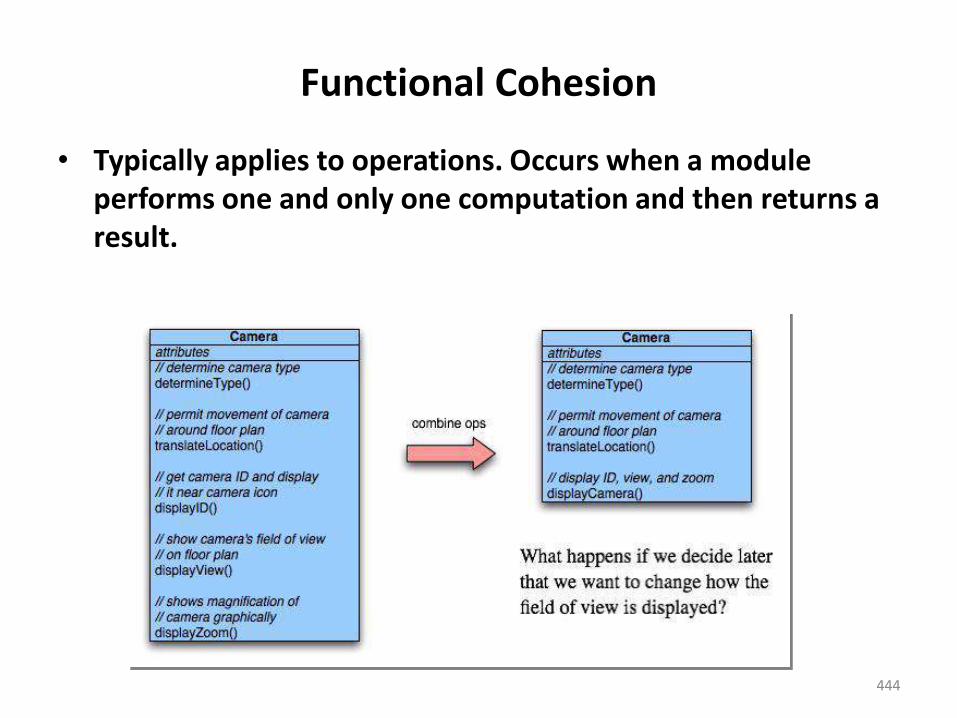
444
Functional Cohesion
• Typically applies to operations. Occurs when a module performs one and only one computation and then returns a result.
445
Layer Cohesion• Form of cohesion in which the facilities for providing or
accessing a set of services through an API or hardware interface are kept together
• There must also be a strict hierarchy in which higher level layers can access only lower-level layers. In other words, the system is effectively divided into layers
• The set of related services which could form a layer might include:– Services for computation– Services for transmission of messages or data– Services for storage of data– Services for managing security– Services for interacting with users– Services provided by an operating system– Services provided directly by the hardware
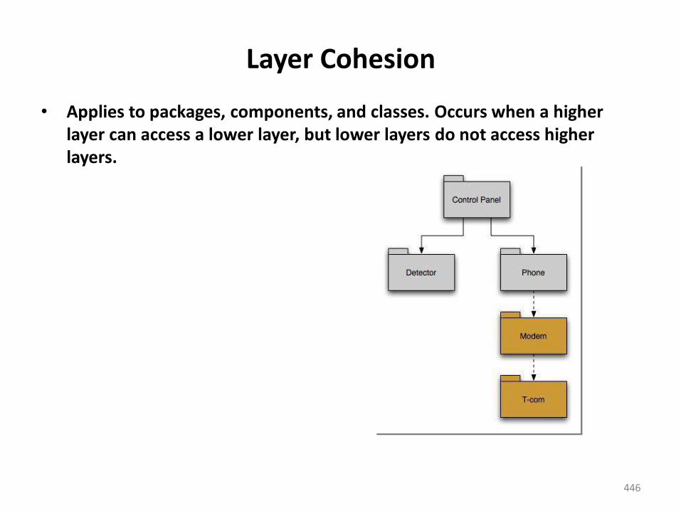
446
Layer Cohesion
• Applies to packages, components, and classes. Occurs when a higher layer can access a lower layer, but lower layers do not access higher layers.
447
Communicational Cohesion
• All operations that access the same data are defined within one class.
• In general, such classes focus solely on the data in question, accessing and storing it.
• Example: A StudentRecord class that adds, removes, updates, and accesses various fields of a student record for client components.
448
Other Types of Cohesion
• Procedural Cohesion– Components or operations are grouped in a manner that allows one
to be invoked immediately after the preceding one was invoked, even when there is no data passed between them
• Sequential Cohesion– Components or operations are grouped in a manner that allows the
first to provide input to the next and so on. The intent is to implement sequence of operations
• Temporal Cohesion– Operations that are performed to reflect a specific behaviour or state
e.g an operation performed at start up or all operations performed when an error is detected
449
Coupling • Coupling or Dependency is the degree to which each program
module relies on each one of the other modules.
• Coupling is usually contrasted with cohesion. Low couplingoften correlates with high cohesion, and vice versa
• Low coupling is often a sign of a well-structured computersystem and a good design, and when combined with highcohesion, supports the general goals of high readability and
maintainability.
450
Coupling
• Coupling can be "low" (also "loose" and "weak") or "high" (also "tight" and "strong"). Types of coupling, are as follows:
• Content coupling (high)
– Content coupling (also known as Pathological coupling) is when one module modifies or relies on the internal workings of another module (e.g., accessing local data of another module).
– Therefore changing the way the second module produces data (location, type, timing) will lead to changing the dependent module.
– Violates information hiding
451
Coupling
• Content coupling (high)
– Example
• module a modifies statements of module b
• module a refers to local data of module b in terms of some numerical displacement within b
• module a branches into local label of module b
– Why is this bad?
• almost any change to b requires changes to a
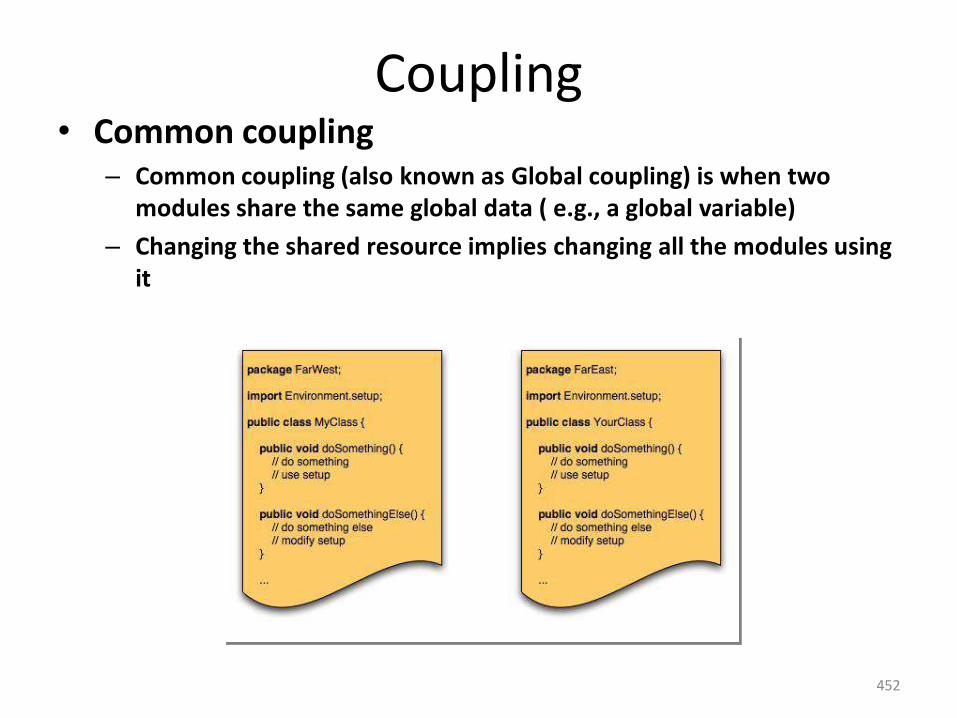
452
Coupling • Common coupling
– Common coupling (also known as Global coupling) is when two modules share the same global data ( e.g., a global variable)
– Changing the shared resource implies changing all the modules using it
453
Coupling
• External coupling– External coupling occurs when two modules share an
externally imposed data format, communication protocol, or device interface. This is basically related to the communication to external tools and devices.
– Occurs when a component communicates or collaborates with infrastructure components ( operating systems, data base capability, telecommunication functions).
– Although this type of coupling is necessary, it should be limited to a small number of components or classes within a system
454
Coupling
• Control coupling– Control coupling is one module controlling the flow of
another, by passing it information on what to do (e.g., passing a what-to-do flag).
– Occurs when operation A() invokes operation B() and passes a control flag. The control flag then “directs” logical flow within B.
– Problem with this form of coupling is that an unrelated change in B can result in the necessity to change the meaning of the control flag that A passes
455
Coupling
• Stamp coupling (Data-structured coupling)
– Stamp coupling is when modules share a composite data structure and use only a part of it, possibly a different part (e.g., passing a whole record to a function that only needs one field of it).
– This may lead to changing the way a module reads a record because a field that the module doesn't need has been modified.
– Occurs when Class B is declared as a type for an argument of an operation of Class A. Because Class B is now part of the definition of Class A, modifying the system becomes more complex
456
Coupling • Data coupling
– Data coupling is when modules share data through, for example,parameters. Each datum is an elementary piece, and these are theonly data shared (e.g., passing an integer to a function that computesa square root).
– Occurs when operations pass long strings of data arguments. Thebandwidth of communication between classes and componentsgrows and the complexity of the interface increases. Testing andmaintenance are more difficult
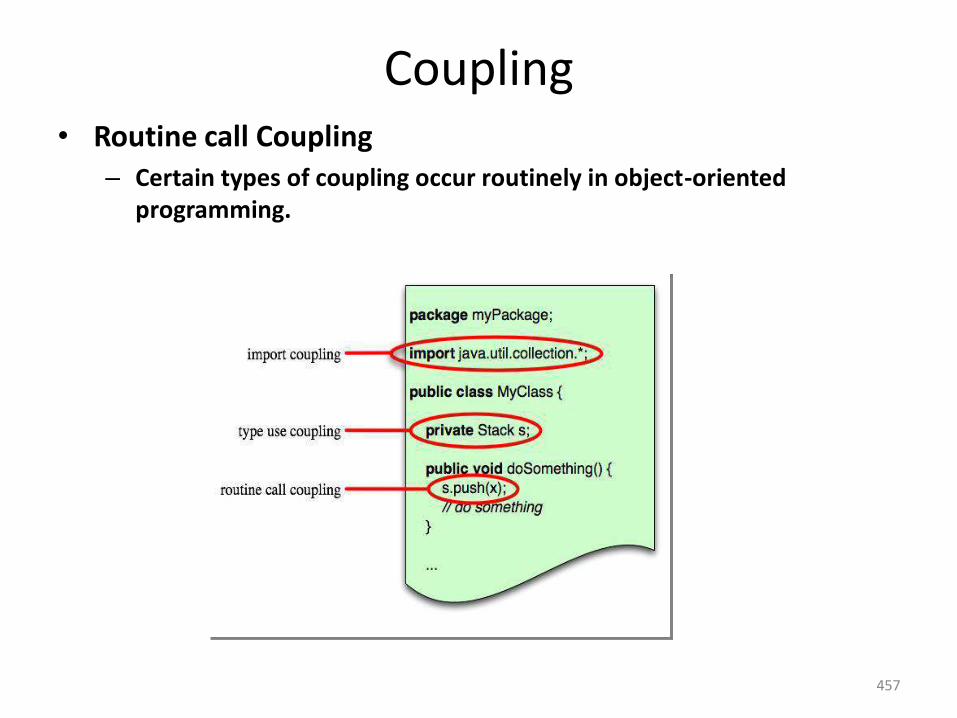
457
Coupling • Routine call Coupling
– Certain types of coupling occur routinely in object-oriented programming.
458
Coupling
• Message coupling (low)
– This is the loosest type of coupling. Component communication is done via parameters or message passing
• Software must communicate internally and externally and hence coupling is essential. However the designer should work to reduce coupling wherever possible and understand the ramifications of high coupling when it cannot be avoided
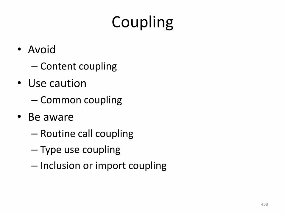
459
Coupling
• Avoid
– Content coupling
• Use caution
– Common coupling
• Be aware
– Routine call coupling
– Type use coupling
– Inclusion or import coupling
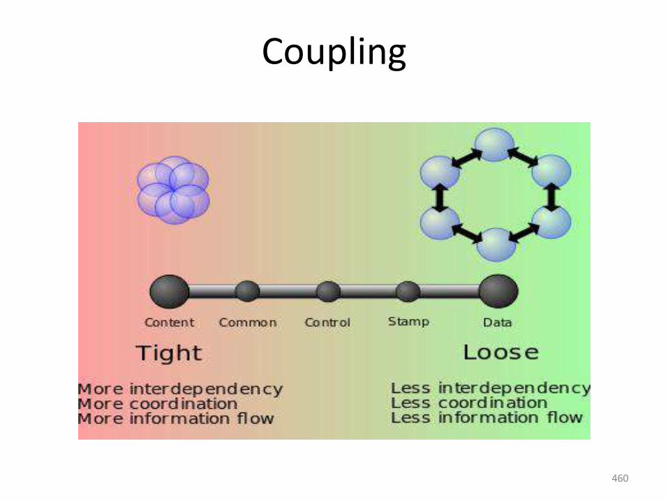
460
Coupling
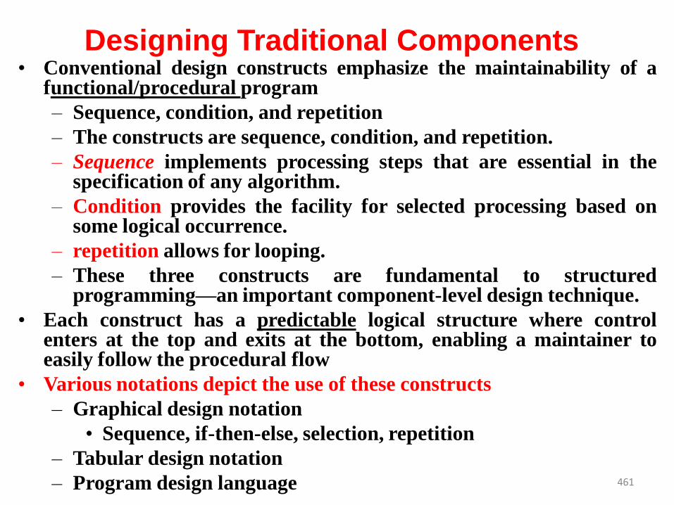
461
Designing Traditional Components• Conventional design constructs emphasize the maintainability of a
functional/procedural program
– Sequence, condition, and repetition
– The constructs are sequence, condition, and repetition.
– Sequence implements processing steps that are essential in thespecification of any algorithm.
– Condition provides the facility for selected processing based onsome logical occurrence.
– repetition allows for looping.
– These three constructs are fundamental to structuredprogramming—an important component-level design technique.
• Each construct has a predictable logical structure where controlenters at the top and exits at the bottom, enabling a maintainer toeasily follow the procedural flow
• Various notations depict the use of these constructs
– Graphical design notation
• Sequence, if-then-else, selection, repetition
– Tabular design notation
– Program design language
Graphical Design Notation• ”A picture is worth a thousand words,” but it’s rather important to know
which picture and which 1000 words.
• There is no question that graphical tools, such as the UML activity diagramor the flowchart, provide useful pictorial patterns that readily depictprocedural detail.
• However, if graphical tools are misused, the wrong picture may lead to thewrong software.
• The activity diagram allows you to represent sequence, condition, andrepetition—
• all elements of structured programming—and is a descendent of an earlierpictorial design representation (still used widely) called a flowchart.
• A flowchart, like an activity diagram, is quite simple pictorially. A box isused to indicate a processing step. A diamond represents a logicalcondition, and arrows show the flow of control. The sequence isrepresented as two processing boxes connected by a line (arrow) ofcontrol.
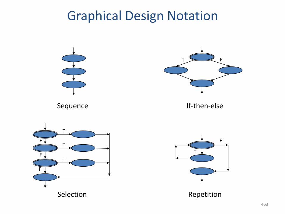
463
Graphical Design Notation
Sequence If-then-else
Selection Repetition
T F
T
T
T
F
F
F
T
F
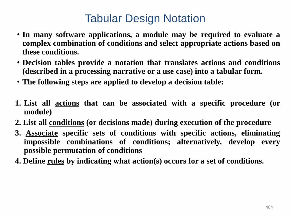
464
Tabular Design Notation
• In many software applications, a module may be required to evaluate acomplex combination of conditions and select appropriate actions based onthese conditions.
• Decision tables provide a notation that translates actions and conditions(described in a processing narrative or a use case) into a tabular form.
• The following steps are applied to develop a decision table:
1. List all actions that can be associated with a specific procedure (ormodule)
2. List all conditions (or decisions made) during execution of the procedure
3. Associate specific sets of conditions with specific actions, eliminatingimpossible combinations of conditions; alternatively, develop everypossible permutation of conditions
4. Define rules by indicating what action(s) occurs for a set of conditions.
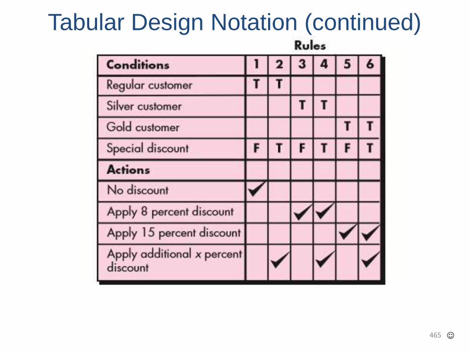
465
Tabular Design Notation (continued)
466
Program Design Language
• Program design language (PDL), also called structured English orpseudocode, incorporates the logical structure of a programminglanguage with the free-form expressive ability of a natural language(e.g., English).
• Narrative text (e.g., English) is embedded within a programminglanguage-like syntax. Automated tools (e.g., [Cai03]) can be used toenhance the application of PDL.
• A basic PDL syntax should include constructs for componentdefinition, interface description, data declaration, block structuring,condition constructs, repetition constructs, and input-output (I/O)constructs.
• PDL can be extended to include keywords for multitasking and/orconcurrent processing, interrupt handling, interprocesssynchronization, and many other features
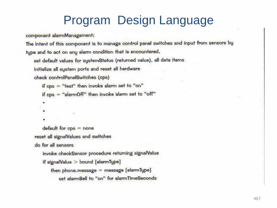
467
Program Design Language
• Program Design Language is also called structured English or psuedocode is a pidgin language in that it uses the vocabulary of one language (English) and the overall syntax of another ( structured programming language)
• Difference between PDL and real programming language lies in the use of narrative text embedded directly within the PDL statements
• PDL cannot be compiled
UNIT- IVTESTING AND IMPLEMENTATION
Software testing fundamentals: Internal andexternal views of testing, white box testing,basis path testing, control structure testing,black box testing, regression testing, unittesting, integration testing, validation testing,system testing and debugging; Softwareimplementation techniques: Coding practices,refactoring.
468
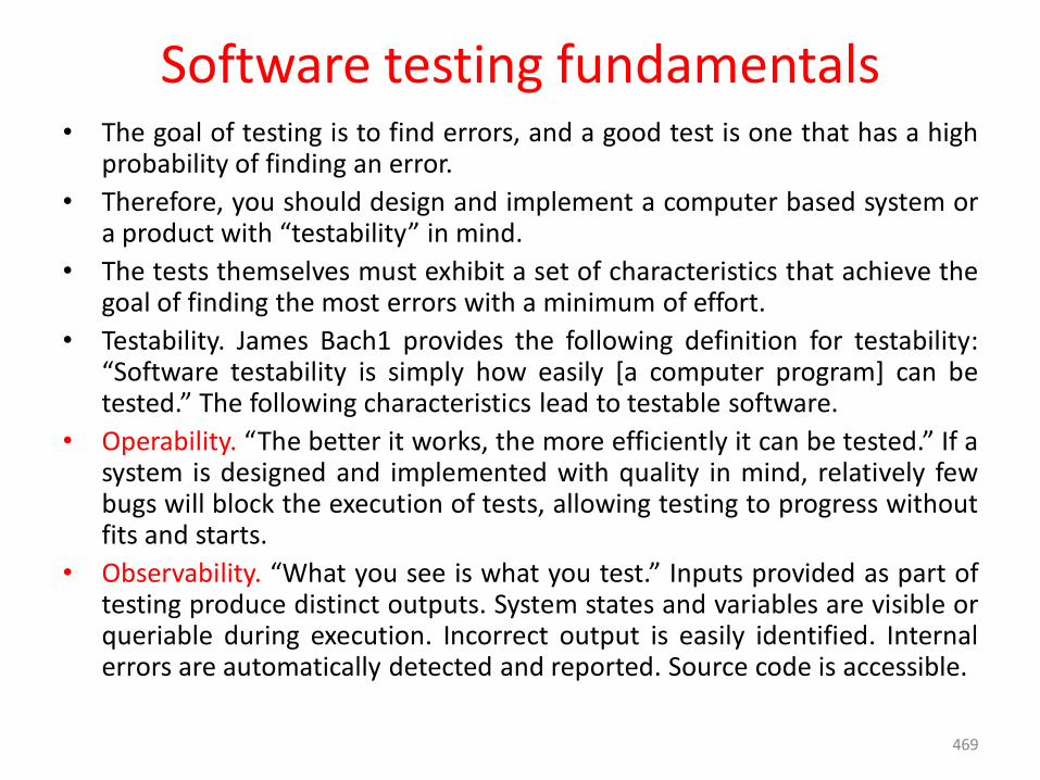
Software testing fundamentals• The goal of testing is to find errors, and a good test is one that has a high
probability of finding an error.
• Therefore, you should design and implement a computer based system ora product with “testability” in mind.
• The tests themselves must exhibit a set of characteristics that achieve thegoal of finding the most errors with a minimum of effort.
• Testability. James Bach1 provides the following definition for testability:“Software testability is simply how easily [a computer program] can betested.” The following characteristics lead to testable software.
• Operability. “The better it works, the more efficiently it can be tested.” If asystem is designed and implemented with quality in mind, relatively fewbugs will block the execution of tests, allowing testing to progress withoutfits and starts.
• Observability. “What you see is what you test.” Inputs provided as part oftesting produce distinct outputs. System states and variables are visible orqueriable during execution. Incorrect output is easily identified. Internalerrors are automatically detected and reported. Source code is accessible.
469
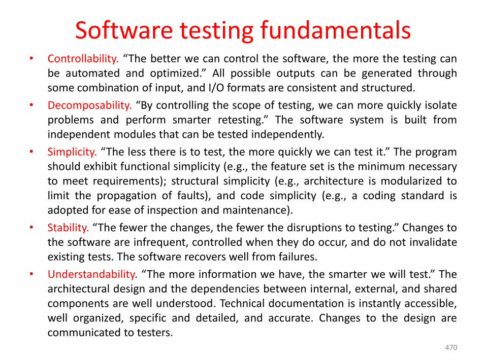
Software testing fundamentals• Controllability. “The better we can control the software, the more the testing can
be automated and optimized.” All possible outputs can be generated throughsome combination of input, and I/O formats are consistent and structured.
• Decomposability. “By controlling the scope of testing, we can more quickly isolateproblems and perform smarter retesting.” The software system is built fromindependent modules that can be tested independently.
• Simplicity. “The less there is to test, the more quickly we can test it.” The programshould exhibit functional simplicity (e.g., the feature set is the minimum necessaryto meet requirements); structural simplicity (e.g., architecture is modularized tolimit the propagation of faults), and code simplicity (e.g., a coding standard isadopted for ease of inspection and maintenance).
• Stability. “The fewer the changes, the fewer the disruptions to testing.” Changes tothe software are infrequent, controlled when they do occur, and do not invalidateexisting tests. The software recovers well from failures.
• Understandability. “The more information we have, the smarter we will test.” Thearchitectural design and the dependencies between internal, external, and sharedcomponents are well understood. Technical documentation is instantly accessible,well organized, specific and detailed, and accurate. Changes to the design arecommunicated to testers.
470
Software testing fundamentals• What are good Test Characteristics (or) What is a “good” test?
• A good test has a high probability of finding an error. To achieve this goal,the tester must understand the software and attempt to develop a mentalpicture of how the software might fail. Ideally, the classes of failure areprobed.
• A good test is not redundant. Testing time and resources are limited. Thereis no point in conducting a test that has the same purpose as another test.Every test should have a different purpose (even if it is subtly different).
• A good test should be “best of breed” . In a group of tests that have asimilar intent, time and resource limitations may mitigate toward theexecution of only a subset of these tests. In such cases, the test that hasthe highest likelihood of uncovering a whole class of errors should beused.
• A good test should be neither too simple nor too complex. Although it issometimes possible to combine a series of tests into one test case, thepossible side effects associated with this approach may mask errors. Ingeneral, each test should be executed separately.
471
Internal and External Views of Testing• Any engineered product (and most other things) can be tested in one of
two ways:
• (1) Knowing the specified function that a product has been designed toperform, tests can be conducted that demonstrate each function isfully operational while at the same time searching for errors in eachfunction.
• (2) Knowing the internal workings of a product, tests can be conducted toensure that “all gears mesh,” that is, internal operations are performedaccording to specifications and all internal components have beenadequately exercised.
• The first test approach takes an external view and is called black-boxtesting. The second requires an internal view and is termed white-boxtesting.
472
Internal and External Views of Testing• Black-box testing alludes to tests that are conducted at the software
interface. A black-box test examines some fundamental aspect of a systemwith little regard for the internal logical structure of the software.
• White-box testing of software is predicated on close examination ofprocedural detail. Logical paths through the software and collaborationsbetween components are tested by exercising specific sets of conditionsand/or loops.
• White-box testing would lead to “100 percent correct programs.” need dois define all logical paths, develop test cases to exercise them, andevaluate results, i.e, generate test cases to exercise program logicexhaustively.
• A limited number of important logical paths can be selected andexercised. Important data structures can be probed for validity.
473
White-Box Testing• White-box testing is the detailed investigation of internal logic and
structure of the code.
• White-box testing, sometimes called glass-box testing or open-box testing.
• It is a test-case design philosophy that uses the control structure describedas part of component-level design to derive test cases.
• The tester needs to have a look inside the source code and find out whichunit/chunk of the code is behaving inappropriately.
• Using White-box testing methods, you can derive test cases that
(1) guarantee that all independent paths within a module have been
exercised at least once,
(2) exercise all logical decisions on their true and false sides,
(3) execute all loops at their boundaries and within their operational
bounds, and
(4) exercise internal data structures to ensure their validity.
474
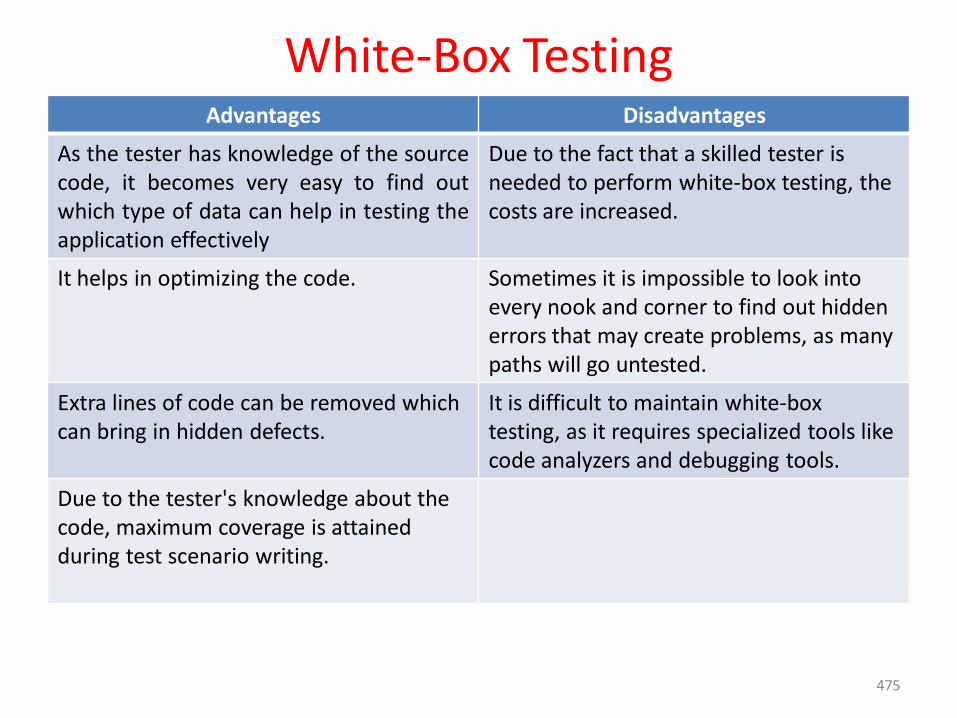
White-Box TestingAdvantages Disadvantages
As the tester has knowledge of the sourcecode, it becomes very easy to find outwhich type of data can help in testing theapplication effectively
Due to the fact that a skilled tester is needed to perform white-box testing, the costs are increased.
It helps in optimizing the code. Sometimes it is impossible to look into every nook and corner to find out hidden errors that may create problems, as many paths will go untested.
Extra lines of code can be removed which can bring in hidden defects.
It is difficult to maintain white-box testing, as it requires specialized tools like code analyzers and debugging tools.
Due to the tester's knowledge about the code, maximum coverage is attained during test scenario writing.
475
Basis Path Testing• Basis path testing is a white-box testing technique.
• The basis path method enables the test-case designer to derive a logicalcomplexity measure of a procedural design and use this measure as a guidefor defining a basis set of execution paths.
• Test cases derived to exercise the basis set are guaranteed to execute everystatement in the program at least one time during testing.
• Flow Graph Notation
• Independent Program Paths
• Deriving Test Cases
• Graph Matrices
476
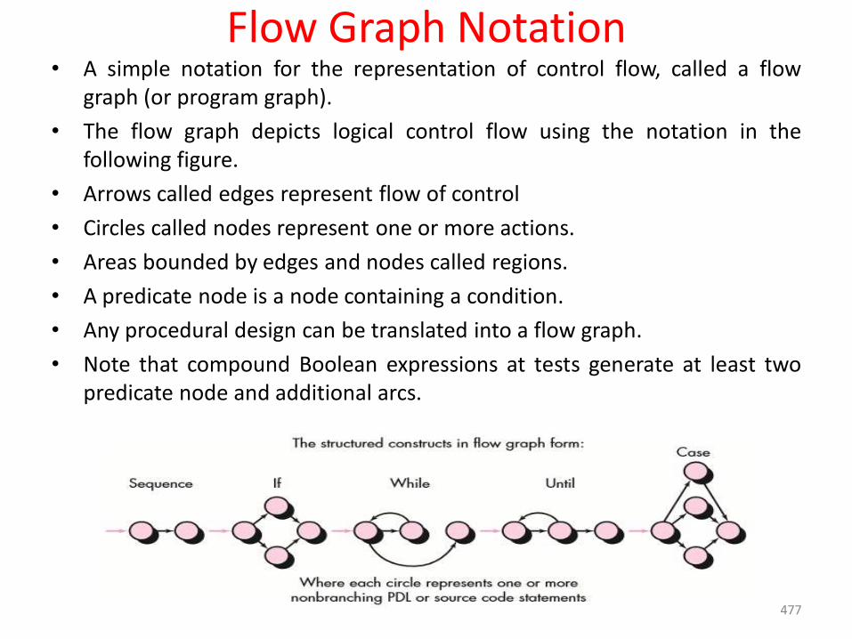
Flow Graph Notation• A simple notation for the representation of control flow, called a flow
graph (or program graph).
• The flow graph depicts logical control flow using the notation in thefollowing figure.
• Arrows called edges represent flow of control
• Circles called nodes represent one or more actions.
• Areas bounded by edges and nodes called regions.
• A predicate node is a node containing a condition.
• Any procedural design can be translated into a flow graph.
• Note that compound Boolean expressions at tests generate at least twopredicate node and additional arcs.
477
Flow Graph Notation• To illustrate the use of a flow graph, consider the procedural design
representation in Figure.
• Here, Figure (a) flow chart is used to depict program control structure.
• Figure(b) maps the flowchart into a corresponding flow graph (assumingthat no compound conditions are contained in the decision diamonds ofthe flowchart).
• Figure(b), each circle, called a flow graph node, represents one or moreprocedural statements.
• A sequence of process boxes and a decision diamond can map into a singlenode.
• The arrows on the flow graph, called edges or links, represent flow ofcontrol and are analogous to flowchart arrows.
• An edge must terminate at a node, even if the node does not representany procedural statements (e.g., see the flow graph symbol for the if-then-else construct).
• Areas bounded by edges and nodes are called regions. When countingregions.
478
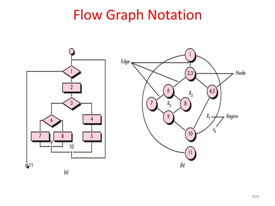
Flow Graph Notation
479
Independent Program Paths• An independent path is any path through the program that introduces at least
one new set of processing statements or a new condition.• Cyclomatic complexity is a software metric that provides a quantitative
measure of the logical complexity if a program.• When used in the context of the basis path testing method, the value
computed for Cyclomatic complexity defines the number of independentpaths in the basis set of a program and provides you with an upper bound forthe number of tests that must be conducted to ensure that all statementshave been executed at least once.
• Cyclomatic complexity has a foundation in graph theory and provides you withan extremely useful software metric. Complexity is computed in one of threeways:
1. The number of regions of the flow graph corresponds to the Cyclomaticcomplexity.
2. Cyclomatic complexity V(G) for a flow graph G is defined asV(G) =E – N + 2 where E is the number of flow graph edges and N is thenumber of flow graph nodes.
3. Cyclomatic complexity V(G) for a flow graph G is also defined as V(G) =P+ 1 where P is the number of predicate nodes contained in the flowgraph G.
480
Deriving Test Cases The following steps can be applied to derive the basis set:
1. Using the design or code as a foundation, draw a corresponding flow graph.
2. Determine the Cyclomatic complexity of the resultant flow graph.
3. Determine a basis set of linearly independent paths.
4. Prepare test cases that will force execution of each path in the basis set.
Graph Matrices:• A data structure, called a graph matrix, can be quite useful for developing
a software tool that assists in basis path testing.
• A graph matrix is a square matrix whose size (i.e., number of rows and columns) is equal to the number of nodes on the flow graph.
• Each row and column corresponds to an identified node, and matrix entries correspond to connections (an edge) between nodes.
481
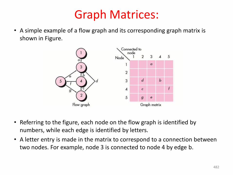
Graph Matrices:• A simple example of a flow graph and its corresponding graph matrix is
shown in Figure.
• Referring to the figure, each node on the flow graph is identified by numbers, while each edge is identified by letters.
• A letter entry is made in the matrix to correspond to a connection between two nodes. For example, node 3 is connected to node 4 by edge b.
482
Graph Matrices:• The graph matrix is nothing more than a tabular representation of a flow
graph.
• By adding a link weight to each matrix entry, the graph matrix can becomea powerful tool for evaluating program control structure during testing.
• The link weight provides additional information about control flow. In itssimplest form, the link weight is 1 (a connection exists) or 0 (a connectiondoes not exist).
483
Control Structure Testing• Although basis path testing is simple and highly effective, it is not sufficient
in itself.
• Other variations on control structure testing necessary. These broadentesting coverage and improve the quality of white-box testing.
1. Condition testing:
• Condition testing is a test-case design method that exercises the logical conditions contained in a program module.
• A simple condition is a Boolean variable or a relational expression, possibly preceded with one NOT (¬) operator.
• A relational expression takes the form
E1<relational-operator> E2
• Where E1 and E2 are arithmetic expressions and <relational-operator> is one of the following:
• A compound condition is composed of two or more simple conditions, Boolean operators, and parentheses.
• The condition testing method focuses on testing each condition in the program to ensure that it does not contain errors.
484
Control Structure Testing2. Data Flow Testing
• The data flow testing method selects test paths of a program according tothe locations of definitions and uses of variables in the program. T
• To illustrate the data flow testing approach, assume that each statementin a program is assigned a unique statement number and that eachfunction does not modify its parameters or global variables.
• For a statement with S as its statement number,
• DEF(S)= {X | statement S contains a definition of X}
• USE(S) = {X | statement S contains a use of X}
• If statement S is an if or loop statement, its DEF set is empty and its USEset is based on the condition of statement S. The definition of variable X atstatement S is said to be live at statement S’ if there exists a path fromstatement S to statement S’ that contains no other definition of X.
485
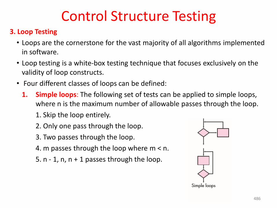
Control Structure Testing3. Loop Testing
• Loops are the cornerstone for the vast majority of all algorithms implemented in software.
• Loop testing is a white-box testing technique that focuses exclusively on the validity of loop constructs.
• Four different classes of loops can be defined:
1. Simple loops: The following set of tests can be applied to simple loops, where n is the maximum number of allowable passes through the loop.
1. Skip the loop entirely.
2. Only one pass through the loop.
3. Two passes through the loop.
4. m passes through the loop where m < n.
5. n - 1, n, n + 1 passes through the loop.
486
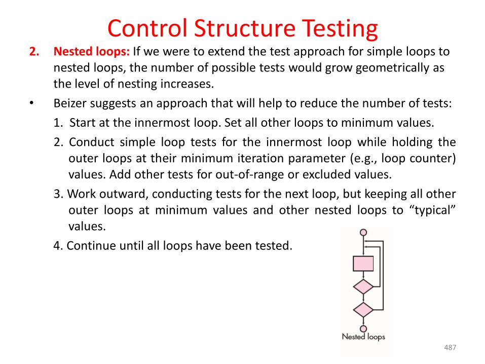
Control Structure Testing2. Nested loops: If we were to extend the test approach for simple loops to
nested loops, the number of possible tests would grow geometrically as the level of nesting increases.
• Beizer suggests an approach that will help to reduce the number of tests:
1. Start at the innermost loop. Set all other loops to minimum values.
2. Conduct simple loop tests for the innermost loop while holding theouter loops at their minimum iteration parameter (e.g., loop counter)values. Add other tests for out-of-range or excluded values.
3. Work outward, conducting tests for the next loop, but keeping all otherouter loops at minimum values and other nested loops to “typical”values.
4. Continue until all loops have been tested.
487
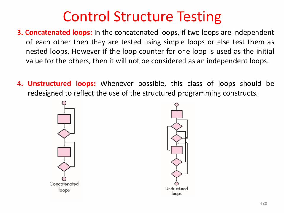
Control Structure Testing3. Concatenated loops: In the concatenated loops, if two loops are independent
of each other then they are tested using simple loops or else test them asnested loops. However if the loop counter for one loop is used as the initialvalue for the others, then it will not be considered as an independent loops.
4. Unstructured loops: Whenever possible, this class of loops should beredesigned to reflect the use of the structured programming constructs.
488
Black-Box Testing• Black-box testing, also called behavioral testing.
• It focuses on the functional requirements of the software.
• Black-box testing techniques enable you to derive sets of input conditionsthat will fully exercise all functional requirements for a program.
• Black-box testing attempts to find errors in the following categories:
(1) incorrect or missing functions
(2) interface errors
(3) errors in data structures or external database access
(4) behavior or performance errors
(5) initialization and termination errors.
Black – Box Testing Techniques
1. Graph-Based Testing Methods 2. Equivalence Partitioning
3. Boundary Value Analysis 4. Orthogonal Array Testing
489
Black-Box Testing1. Graph-Based Testing Methods
• The first step in black-box testing is to understand the objects5 that aremodeled in software and the relationships that connect these objects.
• Next step is to define a series of tests that verify “all objects have the expectedrelationship to one another.
• To accomplish these steps, create a graph—a collection of nodes thatrepresent objects, links that represent the relationships between objects,node weights that describe the properties of a node (e.g., a specific data valueor state behavior), and link weights that describe some characteristic of a link.
• The symbolic representation of a graph is shown in below Figure.
• Nodes are represented as circles connected by links that take a number ofdifferent forms.
• A directed link (represented by an arrow) indicates that a relationship movesin only one direction.
• A bidirectional link, also called a symmetric link, implies that the relationshipapplies in both directions.
• Parallel links are used when a number of different relationships areestablished between graph nodes
490
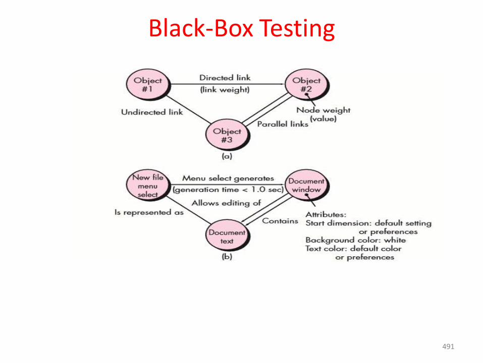
Black-Box Testing
491
Black-Box Testing2. Equivalence Partitioning
• Equivalence partitioning is a black-box testing method that divides the input domain of a program into classes of data from which test cases can be derived.
• Test-case design for equivalence partitioning is based on an evaluation of equivalence classes for an input condition.
• Equivalence classes may be defined according to the following guidelines:
If an input condition specifies a range, one valid and two invalid equivalence classes are defined.
If an input condition requires a specific value, one valid and two invalid equivalence classes are defined.
If an input condition specifies a member of a set, one valid and one invalid equivalence class are defined.
If an input condition is Boolean, one valid and one invalid class are defined.
492
Black-Box Testing3.Boundary Value Analysis
• A greater number of errors occurs at the boundaries of the input domain rather than in the “center of input domain.
• For this reason that boundary value analysis (BVA) has been developed as a testing technique
• Boundary value analysis leads to a selection of test cases that exercise bounding values.
• BVA leads to the selection of test cases at the “edges” of the class. Rather than focusing solely on input conditions.
• BVA derives test cases from the output domain also.
• Guidelines for BVA are similar in many respects to those provided for equivalence partitioning:
1. If an input condition specifies a range bounded by values a and b, testcases should be designed with values a and b and just above and justbelow a and b.
2. If an input condition specifies a number of values, test cases should be
developed that exercise the minimum and maximum numbers. Values
just above and below minimum and maximum are also tested.
493

Black-Box Testing3. Apply guidelines 1 and 2 to out put conditions. For example, assume that a
temperature versus pressure table is required as output from anengineering analysis program. Test cases should be designed to create anoutput report that produces the maximum(and minimum)allowablenumber of table entries.
4. If internal program data structures have prescribed boundaries (e.g., atable has a defined limit of 100 entries), be certain to design a test case toexercise the data structure at its boundary.
Most software engineers intuitively perform BVA to some degree. By applyingthese guidelines, boundary testing will be more complete, thereby having ahigher likelihood for error detection.
494
Black-Box Testing4. Orthogonal Array Testing
• Orthogonal array testing can be applied to problems in which the inputdomain is relatively small but too large to accommodate exhaustive testing.
• The orthogonal array testing method is particularly useful in finding regionfaults—an error category associated with faulty logic within a softwarecompone
• For example, when a train ticket has to be verified, the factors such as - thenumber of passengers, ticket number, seat numbers and the train numbershas to be tested, which becomes difficult when a tester verifies input one byone. Hence, it will be more efficient when he combines more inputs togetherand does testing. Here, use the Orthogonal Array testing method.
• When orthogonal array testing occurs, an L9 orthogonal array of test cases iscreated.
• The L9 orthogonal array has a “balancing property”.
• That is, test cases (represented by dark dots in the figure) are “disperseduniformly throughout the test domain,” as illustrated in the right-hand cube inFigure.
495
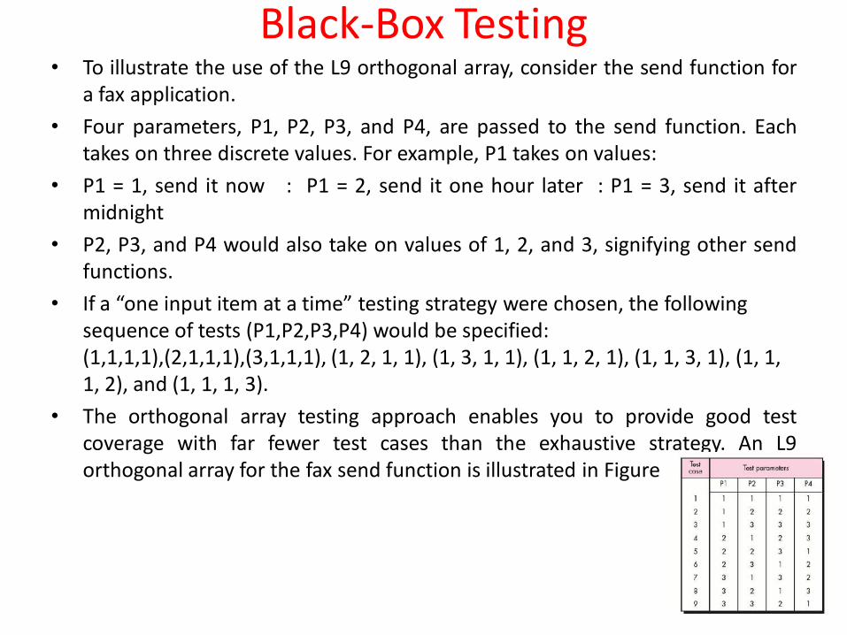
Black-Box Testing• To illustrate the use of the L9 orthogonal array, consider the send function for
a fax application.
• Four parameters, P1, P2, P3, and P4, are passed to the send function. Eachtakes on three discrete values. For example, P1 takes on values:
• P1 = 1, send it now : P1 = 2, send it one hour later : P1 = 3, send it aftermidnight
• P2, P3, and P4 would also take on values of 1, 2, and 3, signifying other sendfunctions.
• If a “one input item at a time” testing strategy were chosen, the following sequence of tests (P1,P2,P3,P4) would be specified: (1,1,1,1),(2,1,1,1),(3,1,1,1), (1, 2, 1, 1), (1, 3, 1, 1), (1, 1, 2, 1), (1, 1, 3, 1), (1, 1, 1, 2), and (1, 1, 1, 3).
• The orthogonal array testing approach enables you to provide good testcoverage with far fewer test cases than the exhaustive strategy. An L9orthogonal array for the fax send function is illustrated in Figure.
496
Regression testing• When any modification or changes are done to the application or even when
any small change is done to the code then it can bring unexpected issues.Along with the new changes it becomes very important to test whether theexisting functionality is intact or not. This can be achieved by doing theregression testing.
• The purpose of the regression testing is to find the bugs which may getintroduced accidentally because of the new changes or modification.
• During confirmation testing the defect got fixed and that part of theapplication started working as intended. But there might be a possibility thatthe fix may have introduced or uncovered a different defect elsewhere in thesoftware. The way to detect these ‘unexpected side-effects’ of fixes is to doregression testing.
• This also ensures that the bugs found earlier are NOT creatable.
• Usually the regression testing is done by automation tools because in order to fix the defect the same test is carried out again and again and it will be very tedious and time consuming to do it manually.
• During regression testing the test cases are prioritized depending upon the changes done to the feature or module in the application. The feature or module where the changes or modification is done that entire feature is taken into priority for testing.
497
Regression testing• This testing becomes very important when there are continuous
modifications or enhancements done in the application or product. Thesechanges or enhancements should NOT introduce new issues in the existingtested code.
• This helps in maintaining the quality of the product along with the newchanges in the application.
• Example:
• Let’s assume that there is an application which maintains the details of allthe students in school. This application has four buttons Add, Save, Deleteand Refresh. All the buttons functionalities are working as expected.Recently a new button ‘Update’ is added in the application. This ‘Update’button functionality is tested and confirmed that it’s working as expected.But at the same time it becomes very important to know that theintroduction of this new button should not impact the other existingbuttons functionality. Along with the ‘Update’ button all the other buttonsfunctionality are tested in order to find any new issues in the existingcode. This process is known as regression testing.
498
Regression testingWhen to use Regression testing it:1. Any new feature is added 2. Any enhancement is done3. Any bug is fixed 4. Any performance related issue is fixed
Advantages of Regression testing:• It helps us to make sure that any changes like bug fixes or any
enhancements to the module or application have not impacted the existing tested code.
• It ensures that the bugs found earlier are NOT creatable.• Regression testing can be done by using the automation tools• It helps in improving the quality of the product.
Disadvantages of Regression testing:• If regression testing is done without using automated tools then it can be
very tedious and time consuming because here we execute the same set of test cases again and again.
• Regression test is required even when a very small change is done in the code because this small modification can bring unexpected issues in the existing functionality.
499
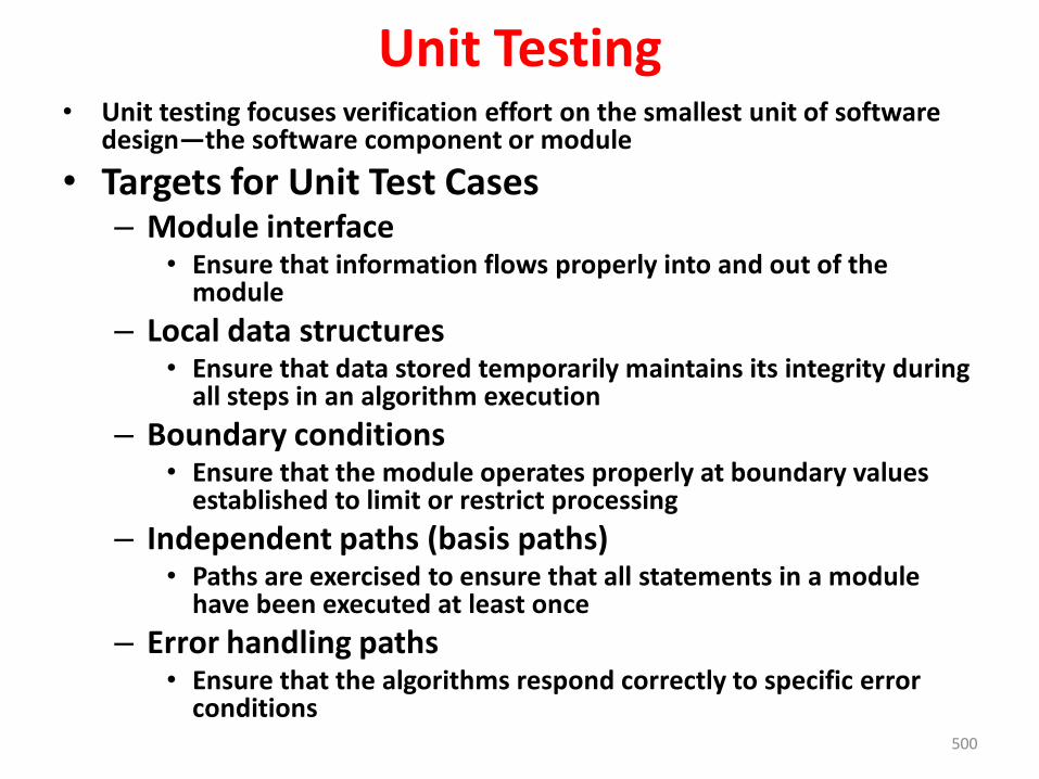
500
Unit Testing• Unit testing focuses verification effort on the smallest unit of software
design—the software component or module
• Targets for Unit Test Cases– Module interface
• Ensure that information flows properly into and out of the module
– Local data structures• Ensure that data stored temporarily maintains its integrity during
all steps in an algorithm execution
– Boundary conditions• Ensure that the module operates properly at boundary values
established to limit or restrict processing
– Independent paths (basis paths)• Paths are exercised to ensure that all statements in a module
have been executed at least once
– Error handling paths• Ensure that the algorithms respond correctly to specific error
conditions
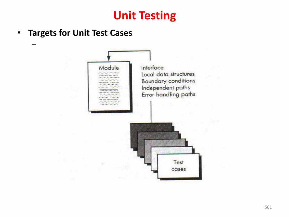
501
Unit Testing
• Targets for Unit Test Cases–
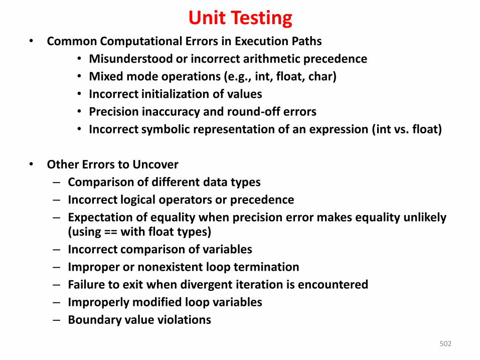
502
Unit Testing• Common Computational Errors in Execution Paths
• Misunderstood or incorrect arithmetic precedence
• Mixed mode operations (e.g., int, float, char)
• Incorrect initialization of values
• Precision inaccuracy and round-off errors
• Incorrect symbolic representation of an expression (int vs. float)
• Other Errors to Uncover
– Comparison of different data types
– Incorrect logical operators or precedence
– Expectation of equality when precision error makes equality unlikely (using == with float types)
– Incorrect comparison of variables
– Improper or nonexistent loop termination
– Failure to exit when divergent iteration is encountered
– Improperly modified loop variables
– Boundary value violations
503
Unit Testing
• Problems to uncover in Error Handling
– Error description is unintelligible or ambiguous
– Error noted does not correspond to error encountered
– Error condition causes operating system intervention prior to error handling
– Exception condition processing is incorrect
– Error description does not provide enough information to assist in the location of the cause of the error
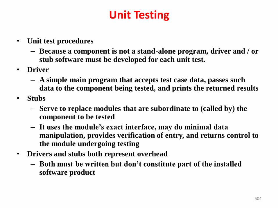
504
Unit Testing
• Unit test procedures
– Because a component is not a stand-alone program, driver and / or stub software must be developed for each unit test.
• Driver
– A simple main program that accepts test case data, passes such data to the component being tested, and prints the returned results
• Stubs
– Serve to replace modules that are subordinate to (called by) the component to be tested
– It uses the module’s exact interface, may do minimal data manipulation, provides verification of entry, and returns control to the module undergoing testing
• Drivers and stubs both represent overhead
– Both must be written but don’t constitute part of the installed software product
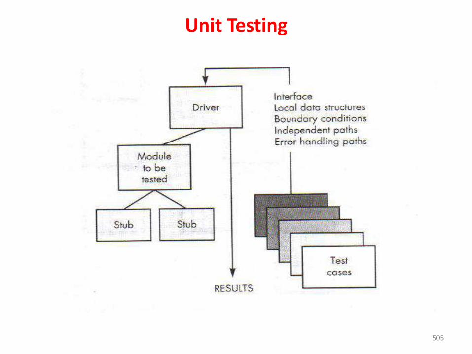
505
Unit Testing
506
Integration TestingIntegration testing is systematic technique for constructing the softwarearchitecture while at the same time conducting tests to cover to uncovererrors associated with interfacing
– Objective is to take unit tested modules and build a program structure based on the prescribed design
– Two Approaches
• Non-incremental Integration Testing
• Incremental Integration Testing
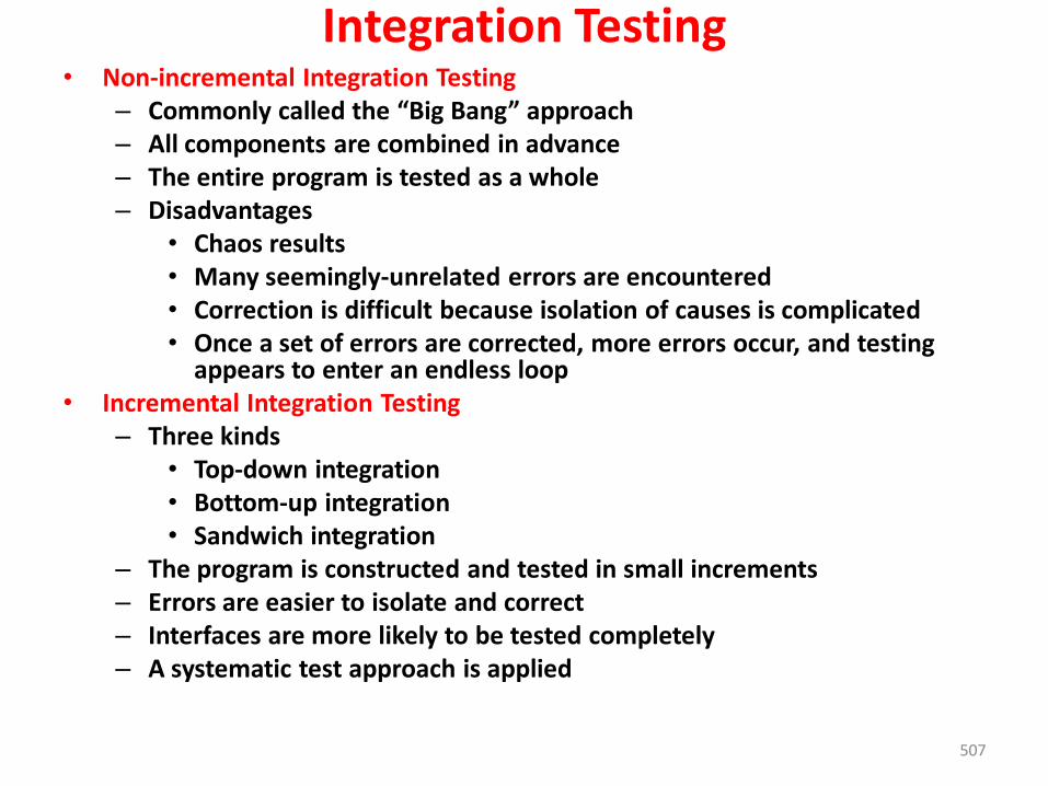
507
Integration Testing• Non-incremental Integration Testing
– Commonly called the “Big Bang” approach– All components are combined in advance– The entire program is tested as a whole– Disadvantages
• Chaos results• Many seemingly-unrelated errors are encountered• Correction is difficult because isolation of causes is complicated• Once a set of errors are corrected, more errors occur, and testing
appears to enter an endless loop• Incremental Integration Testing
– Three kinds • Top-down integration• Bottom-up integration• Sandwich integration
– The program is constructed and tested in small increments– Errors are easier to isolate and correct– Interfaces are more likely to be tested completely– A systematic test approach is applied
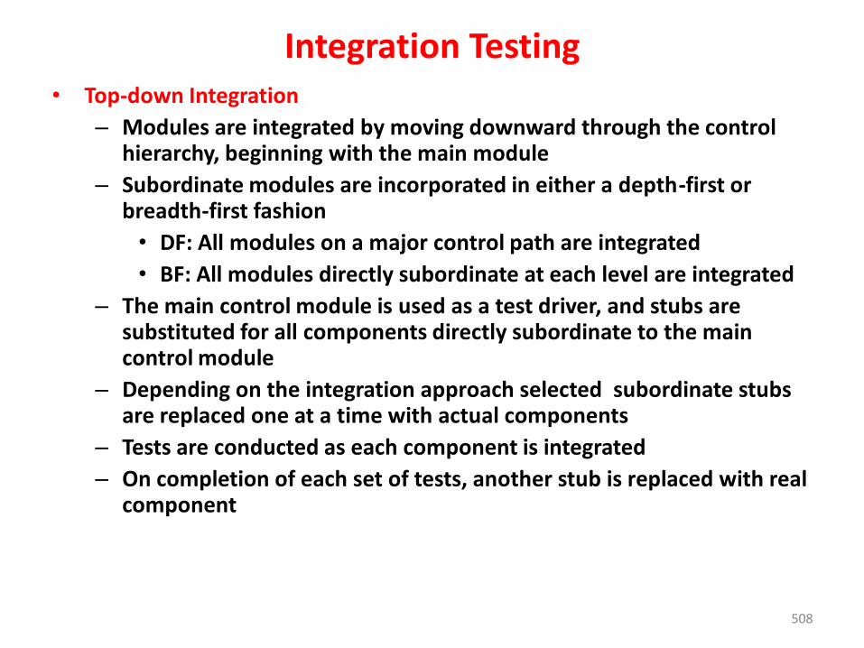
508
Integration Testing• Top-down Integration
– Modules are integrated by moving downward through the control hierarchy, beginning with the main module
– Subordinate modules are incorporated in either a depth-first or breadth-first fashion
• DF: All modules on a major control path are integrated
• BF: All modules directly subordinate at each level are integrated
– The main control module is used as a test driver, and stubs are substituted for all components directly subordinate to the main control module
– Depending on the integration approach selected subordinate stubs are replaced one at a time with actual components
– Tests are conducted as each component is integrated
– On completion of each set of tests, another stub is replaced with real component
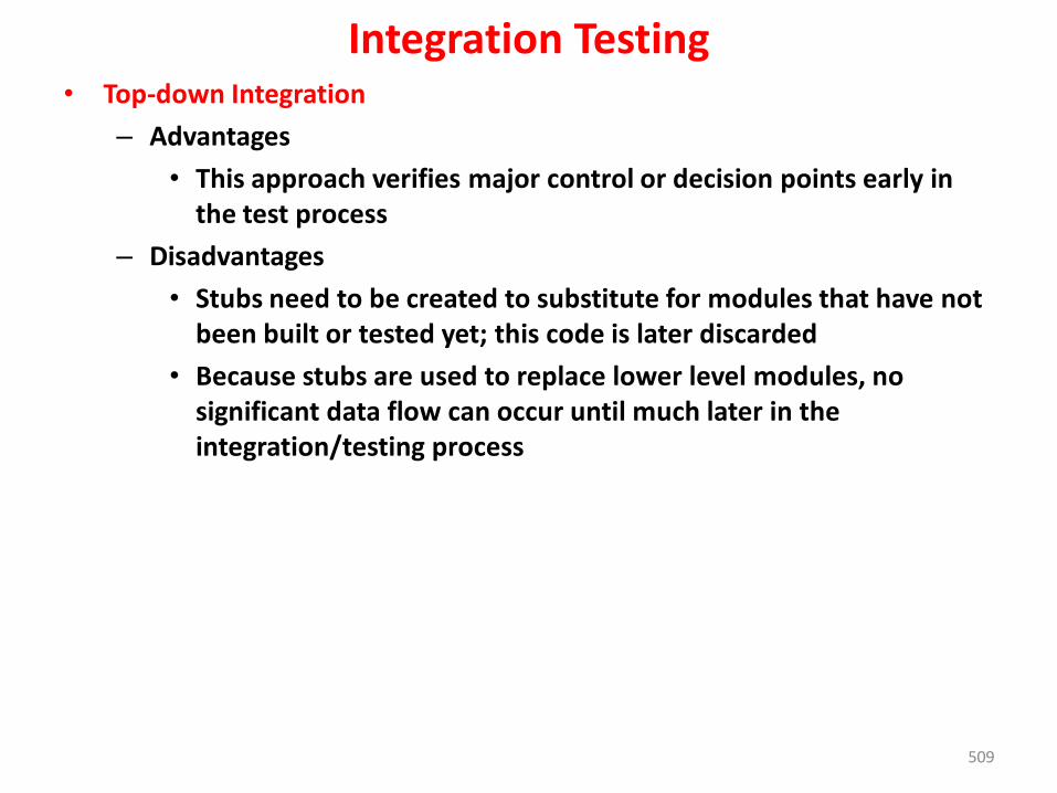
509
Integration Testing• Top-down Integration
– Advantages
• This approach verifies major control or decision points early in the test process
– Disadvantages
• Stubs need to be created to substitute for modules that have not been built or tested yet; this code is later discarded
• Because stubs are used to replace lower level modules, no significant data flow can occur until much later in the integration/testing process
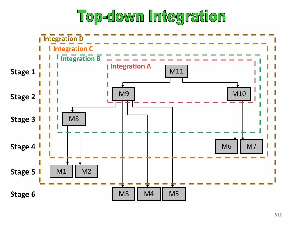
510
M9
M8
M1 M2
M3 M4 M5
M6 M7
M10
M11
Integration C
Integration AIntegration B
Stage 3
Stage 1
Stage 2
Stage 5
Integration D
Stage 4
Stage 6
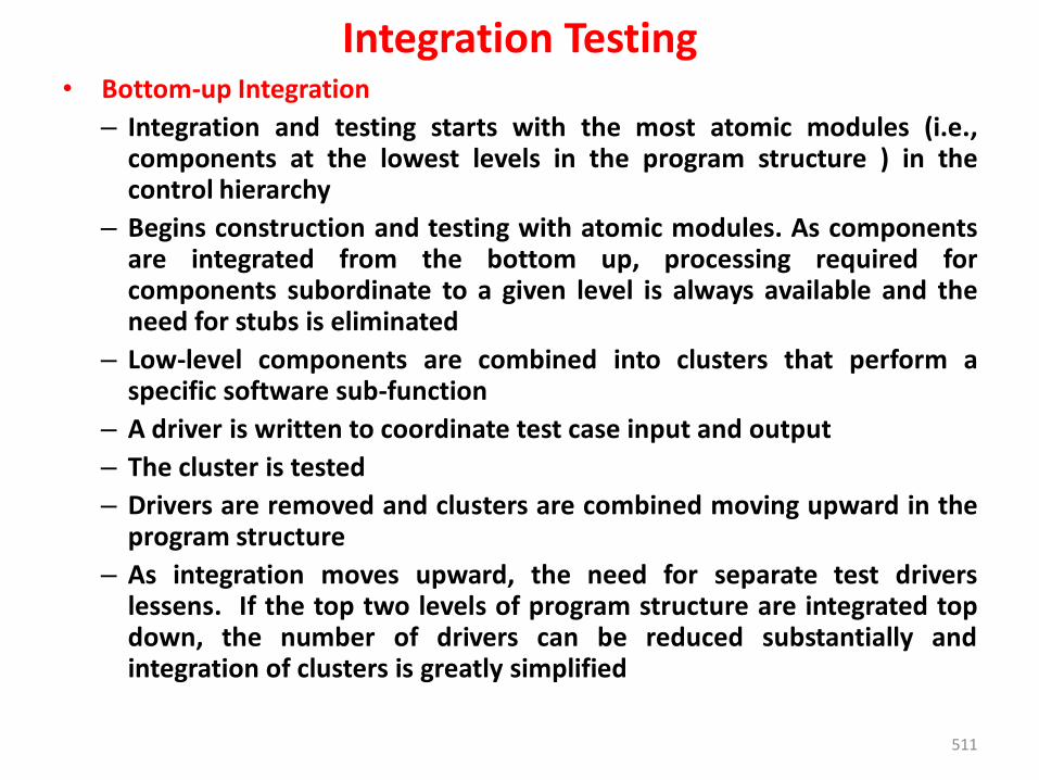
511
Integration Testing• Bottom-up Integration
– Integration and testing starts with the most atomic modules (i.e.,components at the lowest levels in the program structure ) in thecontrol hierarchy
– Begins construction and testing with atomic modules. As componentsare integrated from the bottom up, processing required forcomponents subordinate to a given level is always available and theneed for stubs is eliminated
– Low-level components are combined into clusters that perform aspecific software sub-function
– A driver is written to coordinate test case input and output
– The cluster is tested
– Drivers are removed and clusters are combined moving upward in theprogram structure
– As integration moves upward, the need for separate test driverslessens. If the top two levels of program structure are integrated topdown, the number of drivers can be reduced substantially andintegration of clusters is greatly simplified
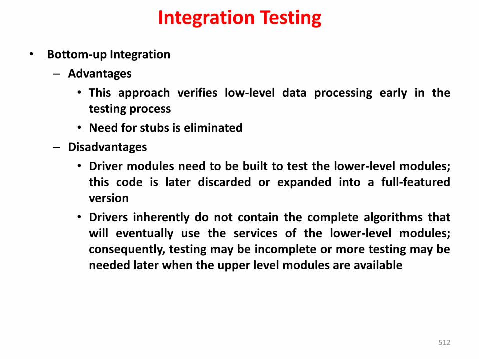
512
Integration Testing
• Bottom-up Integration
– Advantages
• This approach verifies low-level data processing early in thetesting process
• Need for stubs is eliminated
– Disadvantages
• Driver modules need to be built to test the lower-level modules;this code is later discarded or expanded into a full-featuredversion
• Drivers inherently do not contain the complete algorithms thatwill eventually use the services of the lower-level modules;consequently, testing may be incomplete or more testing may beneeded later when the upper level modules are available
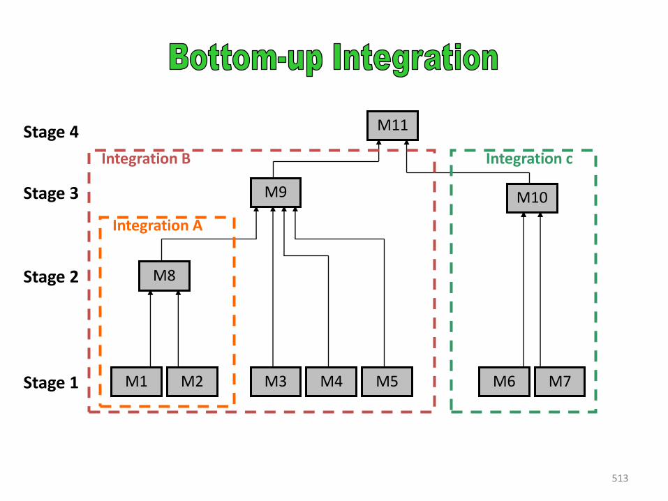
513
M9
M8
M1 M2 M3 M4 M5 M6 M7
M10
M11
Integration A
Integration B Integration c
Stage 2
Stage 4
Stage 3
Stage 1
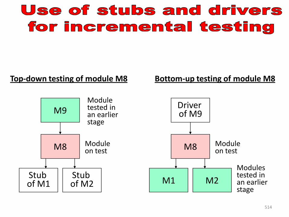
514
Top-down testing of module M8 Bottom-up testing of module M8
Module on test
M9
Stub of M2
Stub of M1
M8 Module on test
Driver of M9
M2M1
M8
Module tested in an earlier stage
Modules tested in an earlier stage
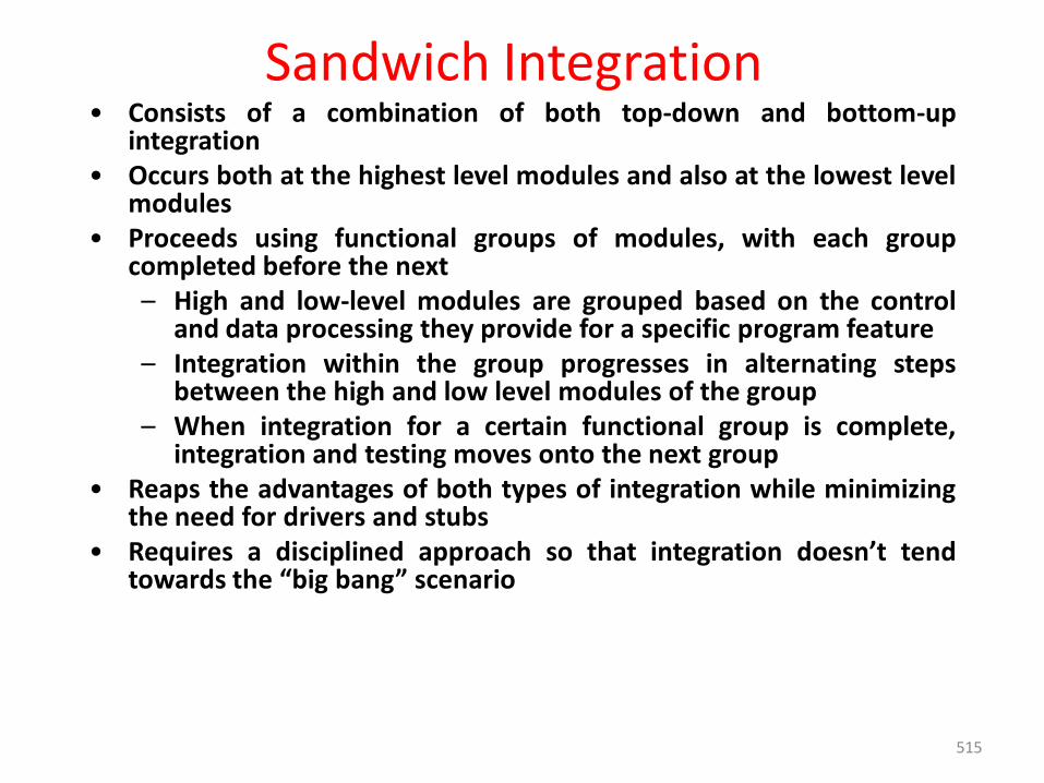
515
Sandwich Integration• Consists of a combination of both top-down and bottom-up
integration• Occurs both at the highest level modules and also at the lowest level
modules• Proceeds using functional groups of modules, with each group
completed before the next– High and low-level modules are grouped based on the control
and data processing they provide for a specific program feature– Integration within the group progresses in alternating steps
between the high and low level modules of the group– When integration for a certain functional group is complete,
integration and testing moves onto the next group• Reaps the advantages of both types of integration while minimizing
the need for drivers and stubs• Requires a disciplined approach so that integration doesn’t tend
towards the “big bang” scenario

516
Regression Testing– Each time a new module is added as part of integration testing, the
software changes.
– New data flow paths are established, new I/O may occur, and newcontrol logic is invoked. These changes may cause problems withfunctions that previously worked flawlessly.
– Regression testing is the re-execution of some subset of tests thathave already been conducted to ensure that changes have notpropagated unintended side effects
– The regression test suite contains
• A representative sample of tests that will exercise all softwarefunctions
• Additional tests that focus on software functions that are likely tobe affected by the change
• Test that focus on the software components that have beenchanged
517
Smoke Testing• Taken from the world of hardware
– Power is applied and a technician checks for sparks, smoke, or other dramatic signs of fundamental failure
• Designed as a pacing mechanism for time-critical projects
– Allows the software team to assess its project on a frequent basis
• Includes the following activities
– The software is compiled and linked into a build
– A series of breadth tests is designed to expose errors that will keep the build from properly performing its function
518
Smoke Testing• The goal is to uncover “show stopper” errors that have the highest
likelihood of throwing the software project behind schedule
– The build is integrated with other builds and the entire product is smoke tested daily
• Daily testing gives managers and practitioners a realistic assessment of the progress of the integration testing
– After a smoke test is completed, detailed test scripts are executed
519
Smoke Testing• Benefits of Smoke Testing
– Integration risk is minimized
• Daily testing uncovers incompatibilities and show-stoppers early in the testing process, thereby reducing schedule impact
– The quality of the end-product is improved
• Smoke testing is likely to uncover both functional errors and architectural and component-level design errors
– Error diagnosis and correction are simplified
• Smoke testing will probably uncover errors in the newest components that were integrated
– Progress is easier to assess
• As integration testing progresses, more software has been integrated and more has been demonstrated to work
• Managers get a good indication that progress is being made
520
Validation Testing• Validation testing follows integration testing
– The distinction between conventional and object-oriented software disappears
– Focuses on user-visible actions and user-recognizable output from the system
– Demonstrates conformity with requirements
1. Validation-Test Criteria
• Designed to ensure that
– All functional requirements are satisfied
– All behavioral characteristics are achieved
– All performance requirements are attained
– Documentation is correct
– Usability and other requirements are met (e.g., transportability, compatibility, error recovery, maintainability)
521
Validation Testing• After each validation test
– The function or performance characteristic conforms tospecification and is accepted
– A deviation from specification is uncovered and a deficiency list iscreated
• Deviation or error discovered at this stage in a project can rarely becorrected prior to scheduled delivery
2. A configuration review or audit ensures that all elements of thesoftware configuration have been properly developed, cataloged, andhave the necessary detail for entering the support phase of thesoftware life cycle (activies)
522
Validation Testing• It is virtually impossible for a software developer to foresee how the
customer will really use a program.
• Instructions for use may be misinterpreted; strange combinations ofdata may be regularly used; output that seemed clear to the tester maybe unintelligible to a user in the field.
• When custom software is built for one customer, a series of acceptancetests are conducted to enable the customer to validate allrequirements. Conducted by the end user rather than softwareengineers, an acceptance test can range from an informal “test drive”to a planned and systematically executed series of tests.
• In fact, acceptance testing can be conducted over a period of weeks ormonths, thereby uncovering cumulative errors that might degrade thesystem over time.
• If software is developed as a product to be used by many customers, itis impractical to perform formal acceptance tests with each one. Mostsoftware product builders use a process called alpha and beta testing touncover errors that only the end user seems able to find.
523
Validation Testing3. Alpha and Beta Testing
– Alpha Testing
• Conducted at the developer’s site by end users
• Software is used in a natural setting with developers watchingintently
• Testing is conducted in a controlled environment
– Beta Testing
• Conducted at end-user sites
• Developer is generally not present
• It serves as a live application of the software in an environmentthat cannot be controlled by the developer Alpha and Beta Testing
– Beta Testing
• The end-user records all problems that are encountered and reports these to the developers at regular intervals
• After beta testing is complete, software engineers make software modifications and prepare for release of the software product to the entire customer base.
524
System Testing• System testing is a series of different test whose primary purpose is to
fully exercise the computer-based system.
• Each test has a different purpose, all work to verify that systemelements have been properly integrated and perform allocatedfunctions.
1. Recovery testing
– Tests for recovery from system faults
– Forces the software to fail in a variety of ways and verifies thatrecovery is properly performed
– Tests reinitialization, checkpointing mechanisms, data recovery,and restart for correctness
– If recovery is automatic, reinitialization, checkpointingmechanisms, data recovery, and restart are evaluated forcorrectness
– If recovery requires human intervention, the mean-time-to-repairis evaluated to determine whether it is within acceptable limits
525
System Testing2. Security testing
– Verifies that protection mechanisms built into a system will, in fact, protect it from improper access
– During security testing, the tester plays the role of the individual who desires to penetrate the system.
– Anything goes! The tester may attempt to acquire passwords through external clerical means.
– may attack the system with custom software designed to break down any defenses that have been constructed
3. Stress testing
– Executes a system in a manner that demands resources in abnormal quantity, frequency, or volume.
– Stress tests are designed to confront programs with abnormal situations. In essence, the tester who performs stress testing asks: “How high can we crank this up before it fails?”
– A variation of stress testing is a technique called sensitivity testing.
System Testing• A very small range of data contained within the bounds of valid data for
a program may cause extreme and even erroneous processing or profound performance degradation.
• Sensitivity testing attempts to uncover data combinations within valid input classes that may cause instability or improper processing.
4. Performance Testing
• Performance testing is designed to test the run-time performance ofsoftware within the context of an integrated system.
• Performance testing occurs throughout all steps in the testing process.Even at the unit level, the performance of an individual module maybe assessed as tests are conducted
• Performance tests are often coupled with stress testing and usuallyrequires both hardware and software instrumentation.
• That is, it is often necessary to measure resource utilization (e.g.,processor cycles) in an exacting fashion
526
System Testing
5. Deployment Testing
• software must execute on a variety of platforms and under more than one operating system environment.
• Deployment testing, sometimes called configuration testing, exercises the software in each environment in which it is to operate.
• Deployment testing examines all installation procedures and specialized installation software (e.g., “installers”) that will be used by customers, and all documentation that will be used to introduce the software to end users.
527
528
The Art of Debugging• Debugging occurs as a consequence of successful testing. When a test case
uncovers an error, debugging is an action that results in the removal of the error.
1. The debugging process
The debugging process attempts to match symptom with cause, thereby leading to error correction.
The debugging process will usually have one of two outcomes:
(1) the cause will be found and corrected or
(2) the cause will not be found. In the latter case, the person performing debugging may suspect a cause, design a test case to help validate that suspicion, and work toward error correction in an iterative fashion.
– Debugging process beings with the execution of a test case. Results are assessed and a lack of correspondence between expected and actual performance is observed
– Debugging attempts to match symptom with cause , thereby leading to error correction .
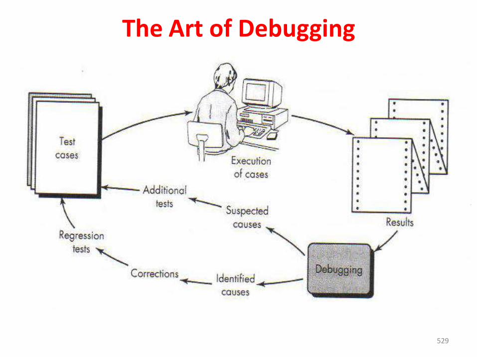
529
The Art of Debugging
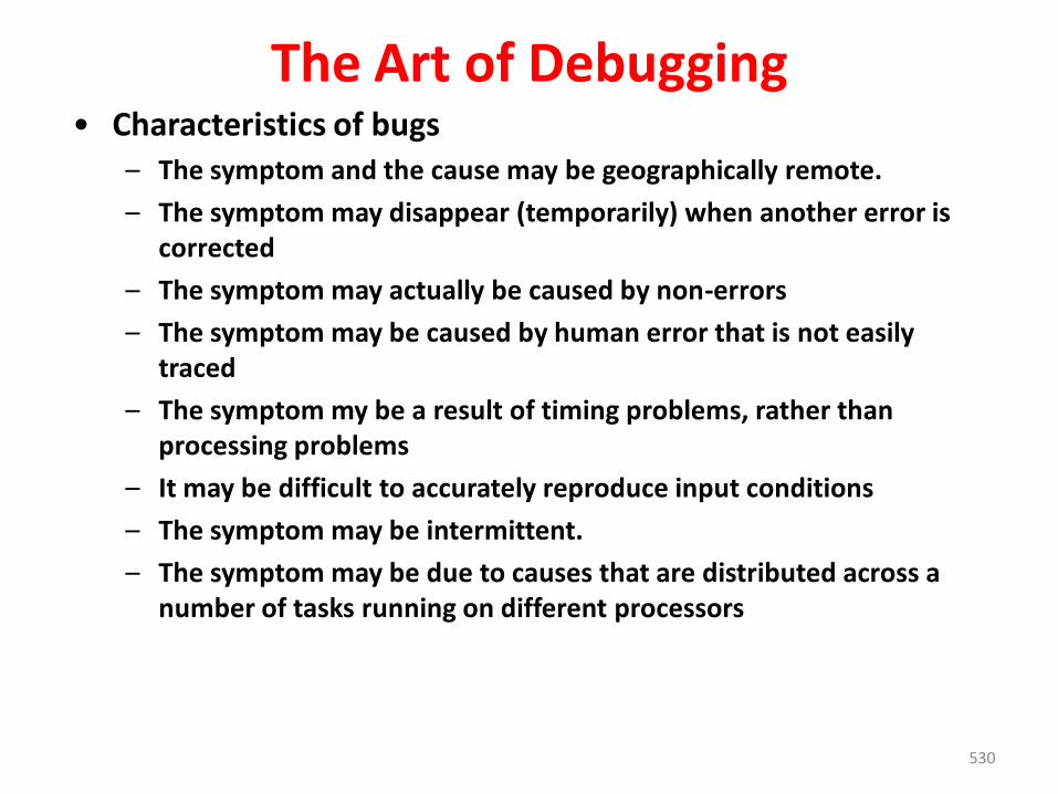
530
The Art of Debugging• Characteristics of bugs
– The symptom and the cause may be geographically remote.
– The symptom may disappear (temporarily) when another error is corrected
– The symptom may actually be caused by non-errors
– The symptom may be caused by human error that is not easily traced
– The symptom my be a result of timing problems, rather than processing problems
– It may be difficult to accurately reproduce input conditions
– The symptom may be intermittent.
– The symptom may be due to causes that are distributed across a number of tasks running on different processors
531
2. Psychological Considerations
• Unfortunately, there appears to be some evidence that debuggingprowess is an innate human trait. Some people are good at it and othersaren’t.
• Although experimental evidence on debugging is open to manyinterpretations, large variances in debugging ability have been reportedfor programmers with the same education and experience.
3. Debugging Strategies
• Objective of debugging is to find and correct the cause of a software error or defect.
• Bugs are found by a combination of systematic evaluation, intuition, and luck.
• Debugging methods and tools are not a substitute for careful evaluation based on a complete design model and clear source code
• There are three main debugging strategies
1. Brute force 2. Backtracking 3. Cause elimination
The Art of Debugging
532
The Art of Debugging• Brute Force
– Most commonly used and least efficient method for isolating the causeof a software error
– Used when all else fails
– Involves the use of memory dumps, run-time traces, and outputstatements
– Leads many times to wasted effort and time
• Backtracking
– Can be used successfully in small programs
– The method starts at the location where a symptom has beenuncovered
– The source code is then traced backward (manually) until the location ofthe cause is found
– In large programs, the number of potential backward paths maybecome unmanageably large
533
The Art of Debugging• Cause Elimination
– Involves the use of induction or deduction and introduces theconcept of binary partitioning
• Induction (specific to general): Prove that a specific startingvalue is true; then prove the general case is true
• Deduction (general to specific): Show that a specificconclusion follows from a set of general premises
– Data related to the error occurrence are organized to isolatepotential causes
– A cause hypothesis is devised, and the aforementioned data areused to prove or disprove the hypothesis
– Alternatively, a list of all possible causes is developed, and testsare conducted to eliminate each cause
– If initial tests indicate that a particular cause hypothesis showspromise, data are refined in an attempt to isolate the bug
534
The Art of Debugging4. Correcting the Error
• Once a bug has been found, it must be corrected.
• But the correction of a bug can introduce other errors and therefore do more harm than good.
• Van Vleck suggests three simple questions that you should ask beforemaking the “correction” that removes the cause of a bug.
• Three Questions to ask Before Correcting the Error
– Is the cause of the bug reproduced in another part of the program?
• Similar errors may be occurring in other parts of the program
– What next bug might be introduced by the fix that I’m about to make?
• The source code (and even the design) should be studied to assessthe coupling of logic and data structures related to the fix
– What could we have done to prevent this bug in the first place?
• This is the first step toward software quality assurance
• By correcting the process as well as the product, the bug will beremoved from the current program and may be eliminated from allfuture programs
Software Implementation TechniquesCoding Practices:
• Best coding practices are a set of informal rules that the softwaredevelopment community has learned over time which can help improvethe quality of software
• Many computer programs remain in use for far longer than the originalauthors ever envisaged (sometimes 40 years or more) so any rules need tofacilitate both initial development and subsequent maintenance andenhancement by people other than the original authors.
• In Ninety-ninety rule, Tim Cargill is credited with this explanation as towhy programming projects often run late: "The first 90% of the codeaccounts for the first 90% of the development time. The remaining 10% ofthe code accounts for the other 90% of the development time." Anyguidance which can redress this lack of foresight is worth considering.
• The size of a project or program has a significant effect on error rates,programmer productivity, and the amount of management needed
a) Maintainability b) Dependability (c) Efficiency
d) Usability.
535
Software Implementation TechniquesRefactoring:• Refactoring is usually motivated by noticing a code smell.• For example the method at hand may be very long, or it may be a near duplicate of another
nearby method.• Once recognized, such problems can be addressed by refactoring the source code, or
transforming it into a new form that behaves the same as before but that no longer "smells".
There are two general categories of benefits to the activity of refactoring.
Maintainability. It is easier to fix bugs because the source code is easy to read andthe intent of its author is easy to grasp. This might be achieved by reducing largemonolithic routines into a set of individually concise, well-named, single-purposemethods. It might be achieved by moving a method to a more appropriate class, orby removing misleading comments.
Extensibility. It is easier to extend the capabilities of the application if it usesrecognizable design patterns, and it provides some flexibility where none beforemay have existed.
• Before applying a refactoring to a section of code, a solid set of automatic unittests is needed. The tests are used to demonstrate that the behavior of the moduleis correct before the refactoring.
• The tests can never prove that there are no bugs, but the important point is thatthis process can be cost-effective: good unit tests can catch enough errors to makethem worthwhile and to make refactoring safe enough.
536
UNIT- VPROJECT MANAGEMENT
Project Management: Estimation: FP based,LOC based, make/buy decision; COCOMO II:Planning, project plan, planning process, RFPrisk management, identification, projection;RMMM: Scheduling and tracking, relationshipbetween people and effort, task set andnetwork, scheduling; EVA: Process and projectmetrics.
Estimation• Software cost and effort estimation will never be an exact science. Too many
variables—human, technical, environmental, political—can affect the ultimate costof software and effort applied to develop it.
• To achieve reliable cost and effort estimates, a number of options arise:1. Delay estimation until late in the project (obviously, we can achieve 100 percent
accurate estimates after the project is complete!).2. Base estimates on similar projects that have already been completed.3. Use relatively simple decomposition techniques to generate project cost and
effort estimates.4. Use one or more empirical models for software cost and effort estimation.
Unfortunately, the first option, however attractive, is not practical. Cost estimatesmust be provided up-front. However, recognize that the longer you wait, the more youknow, and the more you know, the less likely you are to make serious errors in yourestimates.
The second option can work reasonably well, if the current project is quite similar topast efforts and other project influences (e.g., the customer, business conditions, thesoftware engineering environment, deadlines) are roughly equivalent. Unfortunately,past experience has not always been a good indicator of future results.
Estimation• A model is based on experience (historical data) and takes the form
d = f (vi)
• where d is one of a number of estimated values (e.g., effort, cost, projectduration) and vi are selected independent parameters (e.g., estimated LOC orFP).
Function Point based Estimation :
• A Function Point (FP) is a unit of measurement to express the amount ofbusiness functionality, an information system (as a product) provides to a user.FPs measure software size. They are widely accepted as an industry standardfor functional sizing.
• Function point analysis is a method of quantifying the size and complexity of asoftware system in terms of the functions that the system delivers to the user
• It is independent of the computer language, development methodology,technology or capability of the project team used to develop the application
• Function point analysis is designed to measure business applications (notscientific applications)
Estimation• Scientific applications generally deal with complex algorithms that the
function point method is not designed to handle
• Function points are independent of the language, tools, or methodologiesused for implementation (ex. Do not take into consideration programminglanguages, DBMS, or processing hardware)
• Function points can be estimated early in analysis and design
• Uses of Function Point:
• Measure productivity (ex. Number of function points achieved per workhour expended)
• Estimate development and support (cost benefit analysis, staffingestimation)
• Monitor outsourcing agreements (Ensure that the outsourcing entitydelivers the level of support and productivity gains that they promise)
• Drive IS related business decisions (Allow decisions regarding theretaining, retiring and redesign of applications to be made)
• Normalize other measures (Other measures, such as defects, frequentlyrequire the size in function points)
Estimation• LOC based estimation
• Source lines of code (SLOC), also known as lines of code (LOC), is a software metric used to measure the size of a computer program by counting the number of lines in the text of the program's source code.
• SLOC is typically used to predict the amount of effort that will be required to developa program, as well as to estimate programming productivity or maintainability oncethe software is produced.
• Lines used for commenting the code and header file are ignored.
• Two major types of LOC:
1. Physical LOC
• Physical LOC is the count of lines in the text of the program's source code includingcomment lines.
• Blank lines are also included unless the lines of code in a section consists of morethan 25% blank lines.
2. Logical LOC
• Logical LOC attempts to measure the number of executable statements, but theirspecific definitions are tied to specific computer languages.
• Ex: Logical LOC measure for C-like programming languages is the number ofstatement-terminating semicolons(;)
EstimationLOC‐based EstimationThe problems of lines of code (LOC)– Different languages lead to different lengths of code– It is not clear how to count lines of code– A report, screen, or GUI generator can generate thousands of lines of code
in minutes– Depending on the application, the complexity of code is different.
make/buy decision• In many software application areas, it is often more cost effective to acquire
rather than develop computer software.
• Software engineering managers are faced with a make/ buy decision that can be further complicated by a number of acquisition options.
(1) Software may be purchased (or licensed) off-the-shelf
(2) “full-experience” or “partial-experience” software components may beacquired and then modified and integrated to meet specific needs.
(3) Software may be custom built by an outside contractor to meet thepurchaser’s specifications.
• In the final analysis the make/buy decision is made based on the following conditions:
(1) Will the delivery date of the software product be sooner than that for internally developed software?
(2) Will the cost of acquisition plus the cost of customization be less than the cost of developing the software internally?
(3) Will the cost of outside support (e.g., a maintenance contract) be less than the cost of internal support?
make/buy decisionCreating a Decision Tree :
• The steps just described can be augmented using statistical techniquessuch as decision tree analysis.
• For example, considered the figure below it depicts a decision tree for asoftware based system X. In this case, the software engineeringorganization can
(1) build system X from scratch
(2) reuse existing partial-experience components to construct the system
(3) buy an available software product and modify it to meet local needs, or(4) contract the software development to an outside vendor.
If the system is to be built from scratch, there is a 70 percent probability thatthe job will be difficult.
The expected value for cost, computed along any branch of the decision tree,is:
where i is the decision tree path. For the build path.
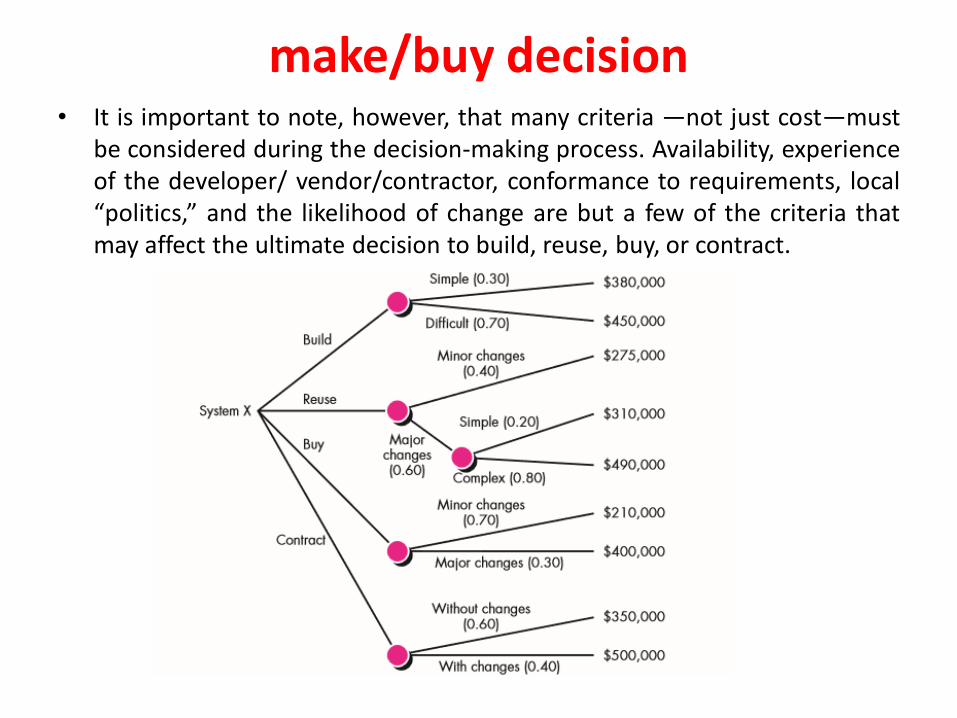
make/buy decision• It is important to note, however, that many criteria —not just cost—must
be considered during the decision-making process. Availability, experienceof the developer/ vendor/contractor, conformance to requirements, local“politics,” and the likelihood of change are but a few of the criteria thatmay affect the ultimate decision to build, reuse, buy, or contract.
make/buy decisionOutsourcing
• Sooner or later, every company that develops computer software asks afundamental question: “Is there a way that we can get the software andsystems we need at a lower price?”
• The answer to this question is not a simple one, and the emotionaldiscussions that occur in response to the question always lead to a singleword: outsourcing. Regardless of the breadth of focus, the outsourcingdecision is often a financial one.
• Outsourcing is extremely simple. Software engineering activities arecontracted to a third party who does the work at lower cost and,hopefully, higher quality.
• The decision to outsource can be either strategic or tactical.• At the strategic level, business managers consider whether a significant
portion of all software work can be contracted to others.• At the tactical level, a project manager determines whether part or all of a
project can be best accomplished by subcontracting the software work.• On the positive side, cost savings can usually be achieved by reducing the
number of software people and the facilities (e.g., computers,infrastructure) that support them.
• On the negative side, a company loses some control over the softwarethat it needs.
COCOMO II • Barry Boehm [Boe81] introduced a hierarchy of software estimation
models bearing the name COCOMO, for Constructive Cost MOdel. Theoriginal COCOMO model became one of the most widely used anddiscussed software cost estimation models in the industry. It has evolvedinto a more comprehensive estimation model, called COCOMOII.
• COCOMOII is actually a hierarchy of estimation models that address thefollowing areas:
• Application composition model. Used during the early stages of softwareengineering, when prototyping of user interfaces, consideration ofsoftware and system interaction, assessment of performance, andevaluation of technology maturity are paramount.
• Early design stage model. Used once requirements have been stabilizedand basic software architecture has been established.
• Post-architecture-stage model. Used during the construction of thesoftware.
• The COCOMO II models require sizing information.
• Three different sizing options are available as part of the model hierarchy:object points, function points, and lines of source code.
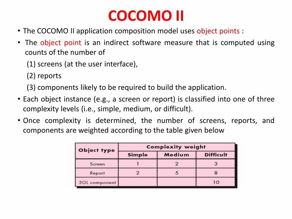
COCOMO II • The COCOMO II application composition model uses object points :
• The object point is an indirect software measure that is computed usingcounts of the number of
(1) screens (at the user interface),
(2) reports
(3) components likely to be required to build the application.
• Each object instance (e.g., a screen or report) is classified into one of threecomplexity levels (i.e., simple, medium, or difficult).
• Once complexity is determined, the number of screens, reports, andcomponents are weighted according to the table given below
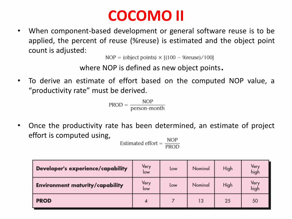
COCOMO II • When component-based development or general software reuse is to be
applied, the percent of reuse (%reuse) is estimated and the object pointcount is adjusted:
where NOP is defined as new object points. • To derive an estimate of effort based on the computed NOP value, a
“productivity rate” must be derived.
• Once the productivity rate has been determined, an estimate of projecteffort is computed using,
The Project Planning Process• The Project Planning Phase is the second phase in the project life cycle. It
involves creating of a set of plans to help guide your team through theexecution and closure phases of the project.
• The plans created during this phase will help you to manage time, cost,quality, change, risk and issues. They will also help you manage staff andexternal suppliers, to ensure that you deliver the project on time andwithin budget.
• The objective of software project planning is to provide a framework thatenables the manager to make reasonable estimates of resources, cost,and schedule.
• In addition, estimates should attempt to define best-case and worst-casescenarios so that project outcomes can be bounded.
• Although there is an inherent degree of uncertainty, the software teamembarks on a plan that has been established as a consequence of thesetasks.
• Therefore, the plan must be adapted and updated as the project proceeds.• The Project Planning Phase is often the most challenging phase for a
Project Manager, as you need to make an educated guess of the staff,resources and equipment needed to complete your project. You may alsoneed to plan your communications and procurement activities, as well ascontract any 3rd party suppliers.
Risk Management• A Hazard is
Any real or potential condition that can cause injury, illness, or death topersonnel; damage to or loss of a system, equipment or property; or damage tothe environment. Simpler .... A threat of harm. A hazard can lead to one orseveral consequences.
• Risk is
The expectation of a loss or damage (consequence)
The combined severity and probability of a loss
The long term rate of loss
A potential problem (leading to a loss) that may - or may not occur in the future.
• Risk Management is A set of practices and support tools to identify, analyze, andtreat risks explicitly.
• Treating a risk means understanding it better, avoiding or reducing it (riskmitigation), or preparing for the risk to materialize.
• Risk management tries to reduce the probability of a risk to occur and theimpact (loss) caused by risks.
Risk Management• Reactive versus Proactive Risk Strategies
• Software risks
Reactive versus Proactive Risk Strategies
• The majority of software teams rely solely on reactive risk strategies. At best, areactive strategy monitors the project for likely risks. Resources are set aside todeal with them, should they become actual problems.
• The software team does nothing about risks until something goes wrong. Then,the team flies into action in an attempt to correct the problem rapidly. This isoften called a fire-fighting mode.
• A considerably more intelligent strategy for risk management is to be proactive.
• A proactive strategy begins long before technical work is initiated. Potentialrisks are identified, their probability and impact are assessed, and they areranked by importance. Then,
• The software team establishes a plan for managing risk. The primary objective isto avoid risk, but because not all risks can be avoided, the team works todevelop a contingency plan that will enable it to respond in a controlled andeffective manner.
Software RisksRisk always involves two characteristics:
• Risk always involves two characteristics: uncertainty—the risk may or may nothappen; that is, there are no 100 percent probable risks—and loss—if the riskbecomes a reality, unwanted consequences or losses will occur.
• When risks are analyzed, it is important to quantify the level of uncertainty andthe degree of loss associated with each risk.
• Different categories of risks are follows:
1. Project risks
Threaten the project plan. That is, if project risks become real, it is likelythat the project schedule will slip and that costs will increase.
Project risks identify potential budgetary, schedule, personnel (staffing andorganization), resource, stakeholder, and requirements problems and theirimpact on a software project.
Software Risks2. Technical risks Threaten the quality and timeliness of the software to be produced. If a technical risk becomes a reality, implementation may become difficult or
impossible. Technical risks identify potential design, implementation, interface,verification, and maintenance problems.
In addition, specification ambiguity, technical uncertainty, technicalobsolescence, and “leading-edge” technology are also risk factors. Technicalrisks occur because the problem is harder to solve than you thought it wouldbe.
3. Business risks Business risks threaten the viability of the software to be built and often
jeopardize the project or the product. Candidates for the top five business risks are
(1) building an excellent product or system that no one really wants (marketrisk)
(2) building a product that no longer fits into the overall business strategy forthe company (strategic risk)
(3) building a product that the sales force doesn’t understand how to sell (salesrisk)
(4) losing the support of senior management due to a change in focus or achange in people (management risk)
(5) losing budgetary or personnel commitment (budget risks).
Software RisksAnother general categorization of risks has been proposed by Charette.
1. Known risks are those that can be uncovered after careful evaluation ofthe project plan, the business and technical environment in which theproject is being developed, and other reliable information sources (e.g.,unrealistic delivery date, lack of documented requirements or softwarescope, poor development environment).
2. Predictable risks are extrapolated from past project experience (e.g.,staff turnover, poor communication with the customer, dilution of staffeffort as ongoing maintenance requests are serviced).
3. Unpredictable risks are the joker in the deck. They can and do occur, but
they are extremely difficult to identify in advance.
Risk Identification• Risk identification is a systematic attempt to specify threats to the project
plan (estimates, schedule, resource loading, etc.).
• By identifying known and predictable risks, the project manager takes a firststep toward avoiding them when possible and controlling them whennecessary.
• There are two distinct types of risks: generic risks and product-specificrisks.
• Generic risks are a potential threat to every software project.
• Product-specific risks can be identified only by those with a clearunderstanding of the technology, the people, and the environment that isspecific to the software that is to be built.
• To identify product-specific risks, the project plan and the softwarestatement of scope are examined, and an answer to the following questionis developed: “What special characteristics of this product may threaten ourproject plan?”
Risk Identification• One method for identifying risks is to create a risk item checklist.
• The checklist can be used for risk identification and focuses on some subset ofknown and predictable risks in the following generic subcategories:
• Product size—risks associated with the overall size of the software to be builtor modified.
• Business impact—risks associated with constraints imposed by managementor the marketplace.
• Stakeholder characteristics—risks associated with the sophistication of thestakeholders and the developer’s ability to communicate with stakeholders ina timely manner.
• Process definition—risks associated with the degree to which the softwareprocess has been defined and is followed by the development organization. •Development environment—risks associated with the availability and qualityof the tools to be used to build the product.
• Technology to be built—risks associated with the complexity of the system tobe built and the “newness” of the technology that is packaged by the system.
• Staff size and experience—risks associated with the overall technical andproject experience of the software engineers who will do the work.
Risk IdentificationAssessing Overall Project Risk
The following questions have been derived from risk data obtained by surveying experienced software project managers in different parts of the world.
1. Have top software and customer managers formally committed to support the project?
2. Are end users enthusiastically committed to the project and the system/ product to be built?
3. Are requirements fully understood by the software engineering team and its customers?
4. Have customers been involved fully in the definition of requirements?
5. Do end users have realistic expectations?
6. Is the project scope stable?
7. Does the software engineering team have the right mix of skills?
8. Are project requirements stable?
9. Doestheprojectteamhaveexperiencewiththetechnologytobeimplemented?
10. Is the number of people on the project team adequate to do the job?
11. Do all customer/user constituencies agree on the importance of the project and on the requirements for the system/product to be built
Risk Identification• The project manager identify the risk drivers that affect software risk
components— performance, cost, support, and schedule.
• The risk components are defined in the following manner:
• Performance risk—the degree of uncertainty that the product will meet itsrequirements and be fit for its intended use.
• Cost risk—the degree of uncertainty that the project budget will bemaintained.
• Support risk—the degree of uncertainty that the resultant software will beeasy to correct, adapt, and enhance.
• Schedule risk—the degree of uncertainty that the project schedule will bemaintained and that the product will be delivered on time.
• The impact of each risk driver on the risk component is divided into one offour impact categories—negligible, marginal, critical, or catastrophic.
Risk Projection• Risk projection, also called risk estimation, attempts to rate each risk in two
ways.
(1) The likelihood or probability that the risk is real and
(2) The consequences of the problems associated with the risk, should itoccur
Managers and technical staff to perform four risk projection steps:
1. Establish a scale that reflects the perceived likelihood of a risk.
2. Delineate the consequences of the risk.
3. Estimate the impact of the risk on the project and the product.
4. Assess the overall accuracy of the risk projection so that there will be nomisunderstandings.
The intent of these steps is to consider risks in a manner that leads toprioritization. No software team has the resources to address every possible riskwith the same degree of rigor.
By prioritizing risks, you can allocate resources where they will have the mostimpact.
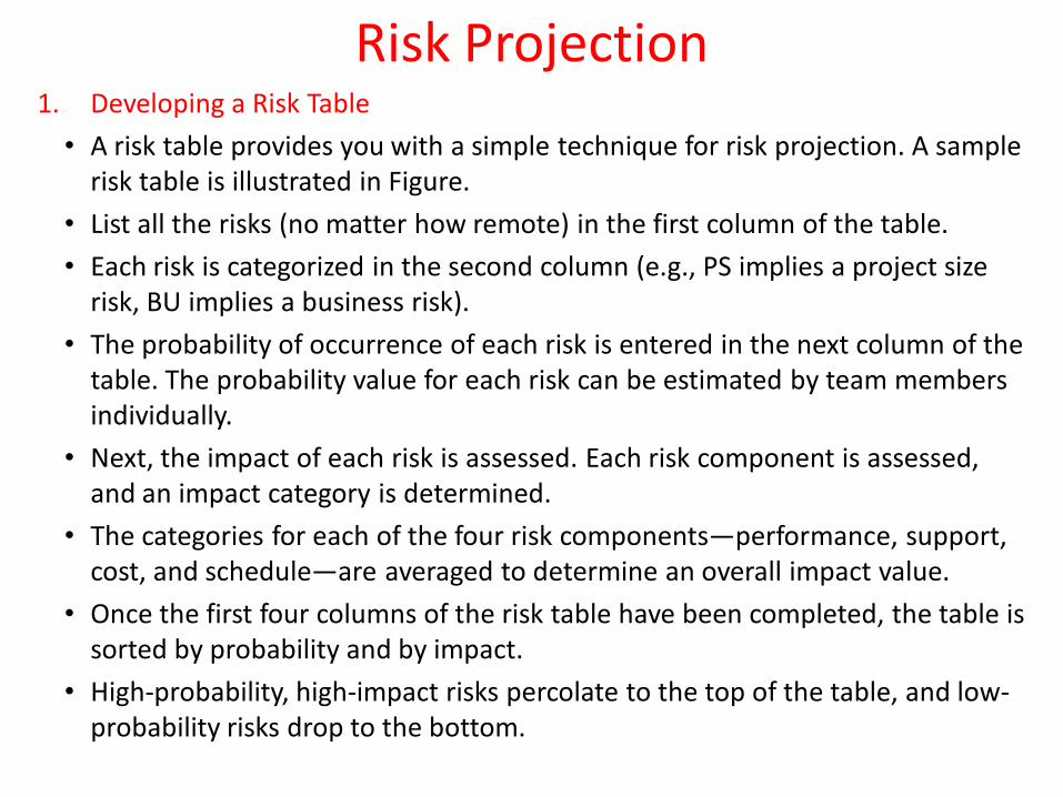
Risk Projection1. Developing a Risk Table
• A risk table provides you with a simple technique for risk projection. A sample risk table is illustrated in Figure.
• List all the risks (no matter how remote) in the first column of the table.
• Each risk is categorized in the second column (e.g., PS implies a project size risk, BU implies a business risk).
• The probability of occurrence of each risk is entered in the next column of the table. The probability value for each risk can be estimated by team members individually.
• Next, the impact of each risk is assessed. Each risk component is assessed, and an impact category is determined.
• The categories for each of the four risk components—performance, support, cost, and schedule—are averaged to determine an overall impact value.
• Once the first four columns of the risk table have been completed, the table is sorted by probability and by impact.
• High-probability, high-impact risks percolate to the top of the table, and low-probability risks drop to the bottom.
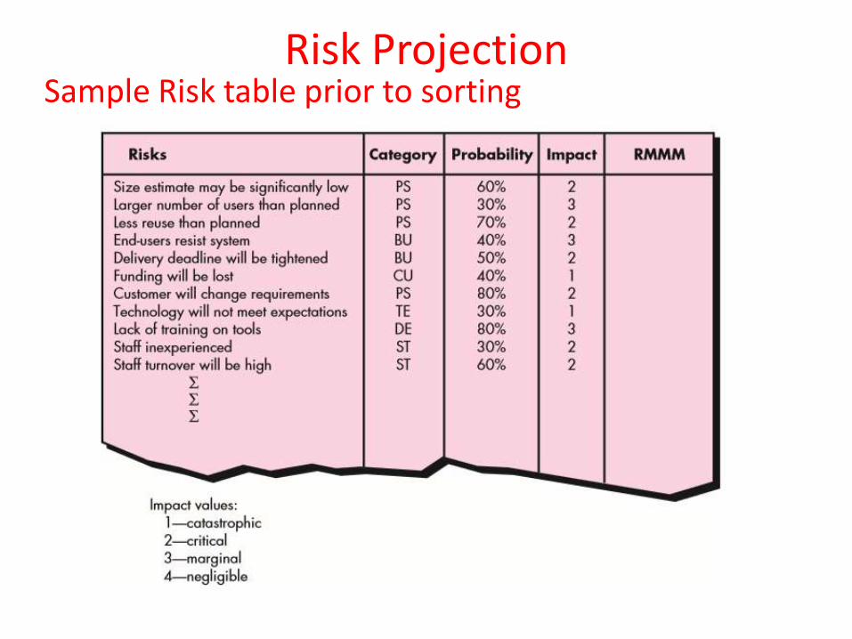
Risk ProjectionSample Risk table prior to sorting
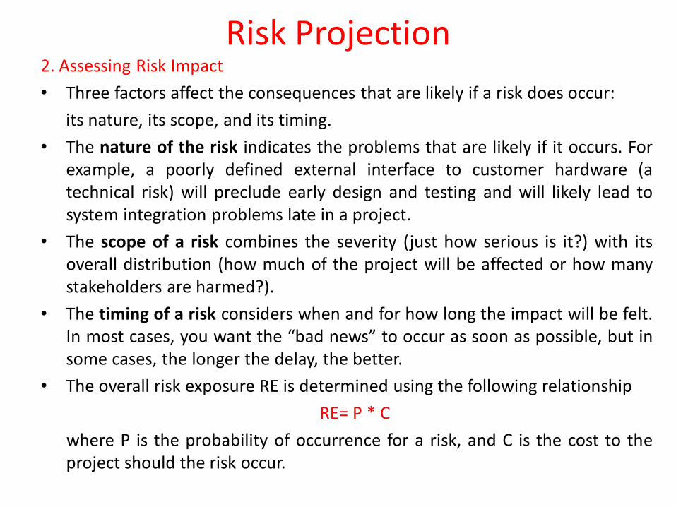
Risk Projection2. Assessing Risk Impact
• Three factors affect the consequences that are likely if a risk does occur:
its nature, its scope, and its timing.
• The nature of the risk indicates the problems that are likely if it occurs. Forexample, a poorly defined external interface to customer hardware (atechnical risk) will preclude early design and testing and will likely lead tosystem integration problems late in a project.
• The scope of a risk combines the severity (just how serious is it?) with itsoverall distribution (how much of the project will be affected or how manystakeholders are harmed?).
• The timing of a risk considers when and for how long the impact will be felt.In most cases, you want the “bad news” to occur as soon as possible, but insome cases, the longer the delay, the better.
• The overall risk exposure RE is determined using the following relationship
RE= P * C
where P is the probability of occurrence for a risk, and C is the cost to theproject should the risk occur.
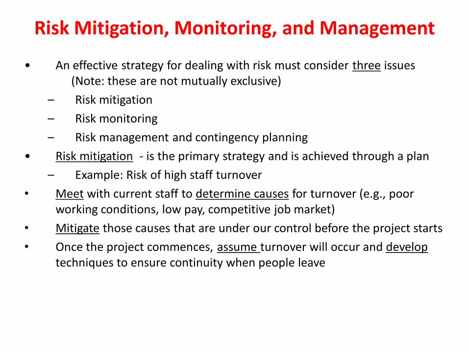
Risk Mitigation, Monitoring, and Management
• An effective strategy for dealing with risk must consider three issues(Note: these are not mutually exclusive)
– Risk mitigation
– Risk monitoring
– Risk management and contingency planning
• Risk mitigation - is the primary strategy and is achieved through a plan
– Example: Risk of high staff turnover
• Meet with current staff to determine causes for turnover (e.g., poor working conditions, low pay, competitive job market)
• Mitigate those causes that are under our control before the project starts
• Once the project commences, assume turnover will occur and developtechniques to ensure continuity when people leave
Risk Mitigation, Monitoring, and Management
• Organize project teams so that information about each developmentactivity is widely dispersed
• Define documentation standards and establish mechanisms to ensurethat documents are developed in a timely manner
• Conduct peer reviews of all work (so that more than one person is "up tospeed")
• Assign a backup staff member for every critical technologist.
• During risk monitoring, the project manager monitors factors that mayprovide an indication of whether a risk is becoming more or less likely
• Risk management and contingency planning assume that mitigationefforts have failed and that the risk has become a reality
Risk Mitigation, Monitoring, and Management
• RMMM steps incur additional project cost– Large projects may have identified 30 – 40 risks
• Risk is not limited to the software project itself– Risks can occur after the software has been delivered to the user
• Software safety and hazard analysis– These are software quality assurance activities that focus on the
identification and assessment of potential hazards that may affectsoftware negatively and cause an entire system to fail
– If hazards can be identified early in the software process, softwaredesign features can be specified that will either eliminate or controlpotential hazards.
• It is important to note that risk mitigation, monitoring, and management(RMMM) steps incur additional project cost
The RMMM Plan
• The RMMM plan may be a part of the software developmentplan or may be a separate document
• Once RMMM has been documented and the project hasbegun, the risk mitigation, and monitoring steps begin
– Risk mitigation is a problem avoidance activity
– Risk monitoring is a project tracking activity
• Risk monitoring has three objectives– To assess whether predicted risks do, in fact, occur
– To ensure that risk aversion steps defined for the risk are beingproperly applied
– To collect information that can be used for future risk analysis
• The findings from risk monitoring may allow the project manager toascertain what risks caused which problems throughout the project

What is PROJECT SCHEDULING?
• In the late 1960s, a bright-eyed young engineer was chosen to“write” a computer program for an automated manufacturingapplication. The reason for his selection was simple. He was theonly person in his technical group who had attended a computerprogramming seminar. He knew the ins and outs of assemblylanguage and FORTRAN but nothing about software engineeringand even less about project scheduling and tracking. His boss gavehim the appropriate manuals and a verbal description of what had tobe done. He was informed that the project must be completed in twomonths. He read the manuals, considered his approach, and beganwriting code. After two weeks, the boss called him into his officeand asked how things were going. “Really great,” said the youngengineer with youthful enthusiasm. “This was much simpler than Ithought. I‟m probably close to 75 percent finished.”
What is PROJECT SCHEDULING?
• The boss smiled and encouraged the young engineer to keep up thegood work. They planned to meet again in a week‟s time. A weeklater the boss called the engineer into his office and asked, “Wherearewe?” “Everything‟s going well,” said the youngster, “but I‟ve runinto a few small snags. I‟ll get them ironed out and be back on tracksoon.” “How does the deadline look?” the boss asked. “Noproblem,” said the engineer. “I‟m close to 90 percent complete.” Ifyou‟ve been working in the software world for more than a fewyears, you can finish the story. It‟ll come as no surprise that theyoung engineer1 stayed 90 percent complete for the entire projectduration and finished (with the help of others) only one month late.This story has been repeated tens of thousands of times by softwaredevelopers during the past five decades. The big question is why?
What is PROJECT SCHEDULING? You’ve selected an appropriate process model.
You’ve identified the software engineering tasks that have to beperformed.
You estimated the amount of work and the number of people, you knowthe deadline, you’ve even considered the risks.
Now it’s time to connect the dots. That is, you have to create a network ofsoftware engineering tasks that will enable you to get the job done ontime.
Once the network is created, you have to assign responsibility for eachtask, make sure it gets done, and adapt the network as risks becomereality.
What is PROJECT SCHEDULING?
Why it’s Important? In order to build a complex system, many software engineering tasks
occur in parallel. The result of work performed during one task may have a profound
effect on work to be conducted in another task. These interdependencies are very difficult to understand without a
schedule. lt’s also virtually impossible to assess progress on a moderate or large
software project without a detailed schedule
What are the steps?
The software engineering tasks dictated by the software process model are refined for the functionality to be built.
Effort and duration are allocated to each task and a task network (also called an “activity network”) is created in a manner that enables the software team to meet the delivery deadline established.
What is PROJECT SCHEDULING?Basic Concept of Project Scheduling
An unrealistic deadline established by someone outside the software development group and forced on managers and practitioner's within the group.
Changing customer requirements that are not reflected in schedule changes.
An honest underestimate of the amount of effort and/or the number of resources that will be required to do the job.
Predictable and/or unpredictable risks that were not considered when the project commenced.
Technical difficulties that could not have been foreseen in advance.
Why should we do when the management demands that we make a dead line I impossible? Perform a detailed estimate using historical data from past projects.
Determine the estimated effort and duration for the project.
Using an incremental process model, develop a software engineering strategy that will deliver critical functionality by the imposed deadline, but delay other functionality until later. Document the plan.
Meet with the customer and (using the detailed estimate), explain why the imposed deadline is unrealistic.
Project SchedulingProject Scheduling
• Basic Principles
• The Relationship Between People and Effort
• Effort Distribution
• Software project scheduling is an action that distributes estimated effort
across the planned project duration by allocating the effort to specific
software engineering tasks.
• During early stages of project planning, a macroscopic schedule is
developed.
• As the project gets under way, each entry on the macroscopic schedule
is refined into a detailed schedule.
Project Scheduling Basic Principles of Project Scheduling.
1. Compartmentalization: The project must be compartmentalized into anumber of manageable activities and tasks. To accomplishcompartmentalization, both the product and the process are refined.
2. Interdependency: The interdependency of each compartmentalized activity ortask must be determined. Some tasks must occur in sequence, while otherscan occur in parallel. Other activities can occur independently.
3. Time allocation: Each task to be scheduled must be allocated some number ofwork units (e.g., person‐days of effort). In addition, each task must beassigned a start date and a completion date. whether work will be conductedon a full-time or part-time basis.
4. Effort validation: Every project has a defined number of people on thesoftware team. The project manager must ensure that no more than theallocated number of people have been scheduled at any given time.
5. Defined responsibilities. Every task that is scheduled should be assigned to aspecific team member.
Project Scheduling6. Defined outcomes: Every task that is scheduled should have a defined
outcome. For software projects, the outcome is normally a work product(e.g., the design of a component) or a part of a work product. Workproducts are often combined in deliverables.
7. Defined milestones: Every task or group of tasks should be associatedwith a project milestone. A milestone is accomplished when one or morework products has been reviewed for quality and has been approved.
Each of these principles is applied as the project schedule evolves.
Project Scheduling•The Relationship Between People and Effort
• In a small software development project a single person can analyzerequirements, perform design, generate code, and conduct tests. As the sizeof a project increases, more people must become involved.
• There is a common myth that is still believed by many managers who areresponsible for software development projects: “If we fall behind schedule,we can always add more programmers and catch up later in the project.”
• Unfortunately, adding people late in a project often has a disruptive effect onthe project, causing schedules to slip even further. The people who are addedmust learn the system, and the people who teach them are the same peoplewho were doing the work.
• While teaching, no work is done, and the project falls further behind. Inaddition to the time it takes to learn the system, more people.
• Although communication is absolutely essential to successful softwaredevelopment, every new communication path requires additional effort andtherefore additional time.
Project SchedulingEffort Distribution• A recommended distribution of effort across the software process is often referred to
as the 40–20–40 rule.
• Forty percent of all effort is allocated to frontend analysis and design. A similarpercentage is applied to back-end testing. You can correctly infer that coding (20percent of effort) is deemphasized.
• Work expended on project planning rarely accounts for more than 2 to 3 percent ofeffort, unless the plan commits an organization to large expenditures with high risk.
• Customer communication and requirements analysis may comprise 10 to 25 percent ofproject effort.
• Effort expended on analysis or prototyping should increase in direct proportion withproject size and complexity.
• A range of 20 to 25 percent of effort is normally applied to software design. Timeexpended for design review and subsequent iteration must also be considered.
• Because of the effort applied to software design, code should follow with relativelylittle difficulty.
• A range of 15 to 20 percent of overall effort can be achieved. Testing and subsequentdebugging can account for 30 to 40 percent of software development effort.
• The criticality of the software often dictates the amount of testing that is required. Ifsoftware is human rated (i.e., software failure can result in loss of life), even higherpercentages are typical.
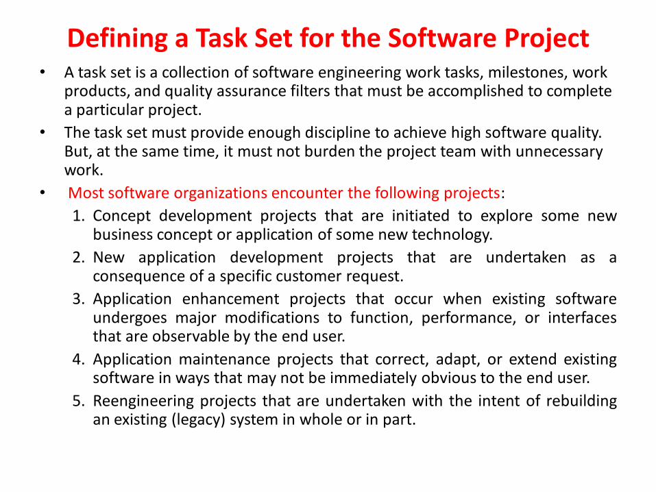
Defining a Task Set for the Software Project• A task set is a collection of software engineering work tasks, milestones, work
products, and quality assurance filters that must be accomplished to complete a particular project.
• The task set must provide enough discipline to achieve high software quality. But, at the same time, it must not burden the project team with unnecessary work.
• Most software organizations encounter the following projects:
1. Concept development projects that are initiated to explore some newbusiness concept or application of some new technology.
2. New application development projects that are undertaken as aconsequence of a specific customer request.
3. Application enhancement projects that occur when existing softwareundergoes major modifications to function, performance, or interfacesthat are observable by the end user.
4. Application maintenance projects that correct, adapt, or extend existingsoftware in ways that may not be immediately obvious to the end user.
5. Reengineering projects that are undertaken with the intent of rebuildingan existing (legacy) system in whole or in part.
Defining a Task Set for the Software Project1. A Task Set Example
• Concept development projects are initiated when the potential for somenew technology must be explored. There is no certainty that thetechnology will be applicable, but a customer (e.g., marketing) believesthat potential benefit exists.
2. Refinement of Software Engineering Actions
• The software engineering actions are used to define a macroscopicschedule for a project.
• The macroscopic schedule must be refined to create a detailed projectschedule.
• Refinement begins by taking each action and decomposing it into a set oftasks (with related work products and milestones).
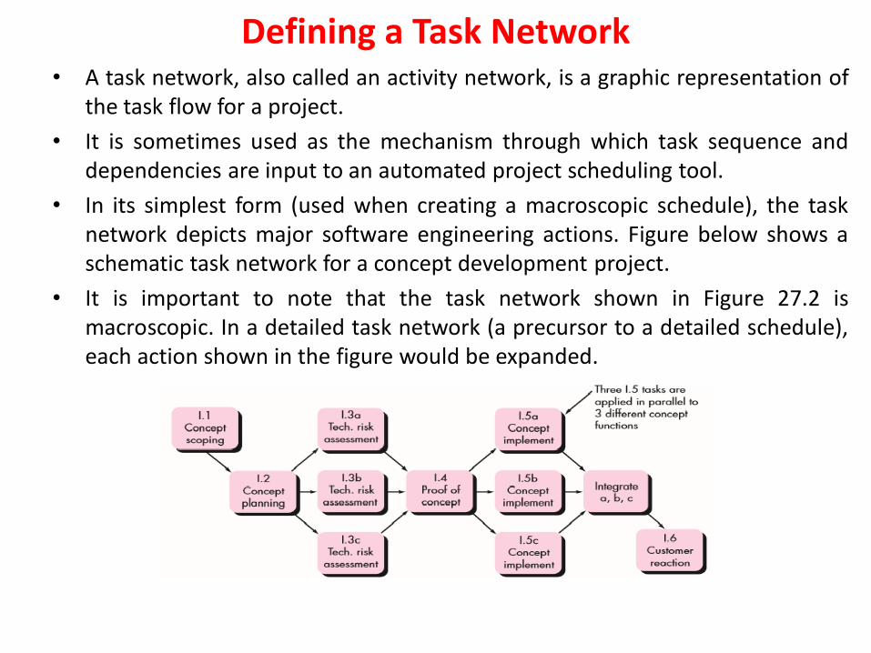
Defining a Task Network• A task network, also called an activity network, is a graphic representation of
the task flow for a project.
• It is sometimes used as the mechanism through which task sequence anddependencies are input to an automated project scheduling tool.
• In its simplest form (used when creating a macroscopic schedule), the tasknetwork depicts major software engineering actions. Figure below shows aschematic task network for a concept development project.
• It is important to note that the task network shown in Figure 27.2 ismacroscopic. In a detailed task network (a precursor to a detailed schedule),each action shown in the figure would be expanded.

Scheduling • Scheduling of a software project does not differ greatly from scheduling of
any multitask engineering effort. Therefore, generalized project schedulingtools and techniques can be applied with little modification for softwareprojects.
• Program evaluation and review technique (PERT) and the critical pathmethod (CPM) are two project scheduling methods that can be applied tosoftware development.
1. Time-Line Charts:
• When creating a software project schedule, begin with a set of tasks.
• If automated tools are used, the work breakdown is input as a tasknetwork or task outline. Effort, duration, and start date are then input foreach task. In addition, tasks may be assigned to specific individuals.
• As a consequence of this input, a time-line chart, also called a Gantt chart,is generated.
• A time-line chart can be developed for the entire project. Alternatively,separate charts can be developed for each project function or for eachindividual working on the project.

Scheduling • All project tasks (for concept scoping) are listed in the left hand column.
The horizontal bars indicate the duration of each task. When multiple barsoccur at the same time on the calendar, task concurrency is implied. Thediamonds indicate milestones.
• Once the information necessary for the generation of a time-line chart has beeninput, the majority of software project scheduling tools produce project tables. —atabular listing of all project tasks, their planned and actual start and end dates, anda variety of related information. Used in conjunction with the time-line chart,project tables enable you to track progress.

Scheduling 2. Tracking the Schedule
• If it has been properly developed, the project schedule becomes a roadmap that defines the tasks and milestones to be tracked and controlled asthe project proceeds.
• Tracking can be accomplished in a number of different ways:
• Conducting periodic project status meetings in which each team memberreports progress and problems.
• Evaluating the results of all reviews conducted throughout the softwareengineering process.
• Determining whether formal project milestones have been accomplishedby the scheduled date.
• Comparing the actual start date to the planned start date for each projecttask listed in the resource table.
• Meeting informally with practitioners to obtain their subjectiveassessment of progress to date and problems on the horizon.
• Using earned value analysis to assess progress quantitatively.
In reality, all of these tracking techniques are used by experienced projectmanagers.
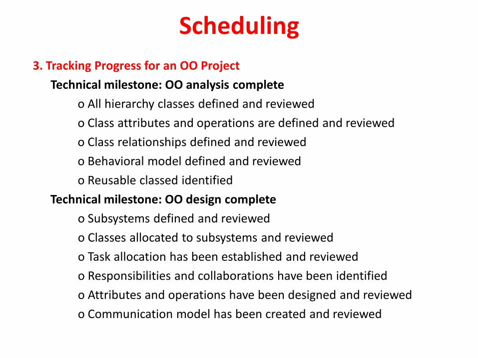
Scheduling
3. Tracking Progress for an OO Project
Technical milestone: OO analysis complete
o All hierarchy classes defined and reviewed
o Class attributes and operations are defined and reviewed
o Class relationships defined and reviewed
o Behavioral model defined and reviewed
o Reusable classed identified
Technical milestone: OO design complete
o Subsystems defined and reviewed
o Classes allocated to subsystems and reviewed
o Task allocation has been established and reviewed
o Responsibilities and collaborations have been identified
o Attributes and operations have been designed and reviewed
o Communication model has been created and reviewed
Scheduling
• Technical milestone: OO programming complete
o Each new design model class has been implemented
o Classes extracted from the reuse library have been implemented
o Prototype or increment has been built
• Technical milestone: OO testing
o The correctness and completeness of the OOA and OOD models hasbeen reviewed
o Class-responsibility-collaboration network has been developed andreviewed
o Test cases are designed and class-level tests have been conducted foreach class
o Test cases are designed, cluster testing is completed, and classes havebeen integrated
o System level tests are complete
Scheduling • Scheduling for WebApp Projects
• WebApp project scheduling distributes estimated effort across theplanned time line (duration) for building each WebApp increment.
• This is accomplished by allocating the effort to specific tasks.
• The overall WebApp schedule evolves over time.
• During the first iteration, a macroscopic schedule is developed.
• This type of schedule identifies all WebApp increments and projects thedates on which each will be deployed.
• As the development of an increment gets under way, the entry for theincrement on the macroscopic schedule is refined into a detailedschedule.
• Here, specific development tasks (required to accomplish an activity) areidentified and scheduled.
EARNED VALUE ANALYSIS• It is reasonable to ask whether there is a quantitative technique for assessing
progress as the software team progresses through the work tasks allocated tothe project schedule.
• A Technique for performing quantitative analysis of progress does exist. It iscalled earned value analysis (EVA).
• To determine the earned value, the following steps are performed:
1. The budgeted cost of work scheduled (BCWS) is determined for each worktask represented in the schedule. During estimation, the work (in person-hours or person-days) of each software engineering task is planned. Hence,BCWSi is the effort planned for work task i. To determine progress at a givenpoint along the project schedule, the value of BCWS is the sum of the BCWSivalues for all work tasks that should have been completed by that point intime on the project schedule.
2. The BCWS values for all work tasks are summed to derive the budget at
completion (BAC). Hence, BAC (BCWSk) for all tasks k
3. Next, the value for budgeted cost of work performed (BCWP) is computed.The value for BCWP is the sum of the BCWS values for all work tasks thathave actually been completed by a point in time on the project schedule.
EARNED VALUE ANALYSIS• Given values for BCWS, BAC, and BCWP, important progress indicators can be
computed:
Schedule performance index, SPI = BCWP / BCWS
Schedule variance, SV = BCWP – BCWS
• SPI is an indication of the efficiency with which the project is utilizing scheduledresources. An SPI value close to 1.0 indicates efficient execution of the projectschedule. SV is simply an absolute indication of variance from the plannedschedule.
• Percent scheduled for completion = BCWS / BAC
provides an indication of the percentage of work that should have beencompleted by time t.
• Percent complete = BCWP / BAC
provides a quantitative indication of the percent of completeness of the projectat a given point in time t. It is also possible to compute the actual cost of workperformed (ACWP). The value for ACWP is the sum of the effort actuallyexpended on work tasks that have been completed by a point in time on theproject schedule. It is then possible to compute
EARNED VALUE ANALYSIS
Cost performance index, CPI = BCWP /ACWP
Cost variance, CV = BCWP - ACWP
A CPI value close to 1.0 provides a strong indication that the project iswithin its defined budget. CV is an absolute indication of cost savings(against planned costs) or shortfall at a particular stage of a project.
Process and Project MetricsWhat are Metrics?
• Software process and project metrics are quantitative measures
• They are a management tool
• They offer insight into the effectiveness of the software process and the
projects that are conducted using the process as a framework
• Basic quality and productivity data are collected
• These data are analyzed, compared against past averages, and assessed
• The goal is to determine whether quality and productivity
improvements have occurred
• The data can also be used to pinpoint problem areas
• Remedies can then be developed and the software process can be
improved
Reasons to Measure
To characterize in order to
Gain an understanding of processes, products, resources, and environments Establish baselines for comparisons with future
assessments
To evaluate in order to Determine status with respect to plans
To predict in order to
Gain understanding of relationships among processes and products Build models of these relationships
To improve in order to
Identify roadblocks, root causes, inefficiencies, and other opportunities for improving product quality and process performance
Process and Project Metrics
• Process metrics are collected across all projects and over long periods of time.
• Their intent is to provide a set of process indicators that lead to long-term software process improvement.
• Project metrics enable a software project manager to
• assess the status of an ongoing project,• track potential risks,• uncover problem areas before they go “critical,”• adjust work flow or tasks,
• evaluate the project team’s ability to control quality of software work products
Metrics In The Process and Project Domains
Process Metrics and Software Process Improvement:-
• Software process improvement, it is important to note that process is onlyone of a number of “controllable factors in improving software quality and
organizational performance”.
• Process sits at the center of a triangle connecting three factors that have aprofound influence on software quality and organizational performance.
• The skill and motivation of people has been shown to be the single mostinfluential factor in quality and performance.
• The complexity of the product can have a substantial impact on quality andteam performance.
• The technology (i.e., the software engineering methods and tools) thatpopulates the process also has an impact.
• In addition, the process triangle exists within a circle of environmentalconditions that include the development environment (e.g., integratedsoftware tools), business conditions (e.g., deadlines, business rules), andcustomer characteristics (e.g., ease of communication and collaboration).
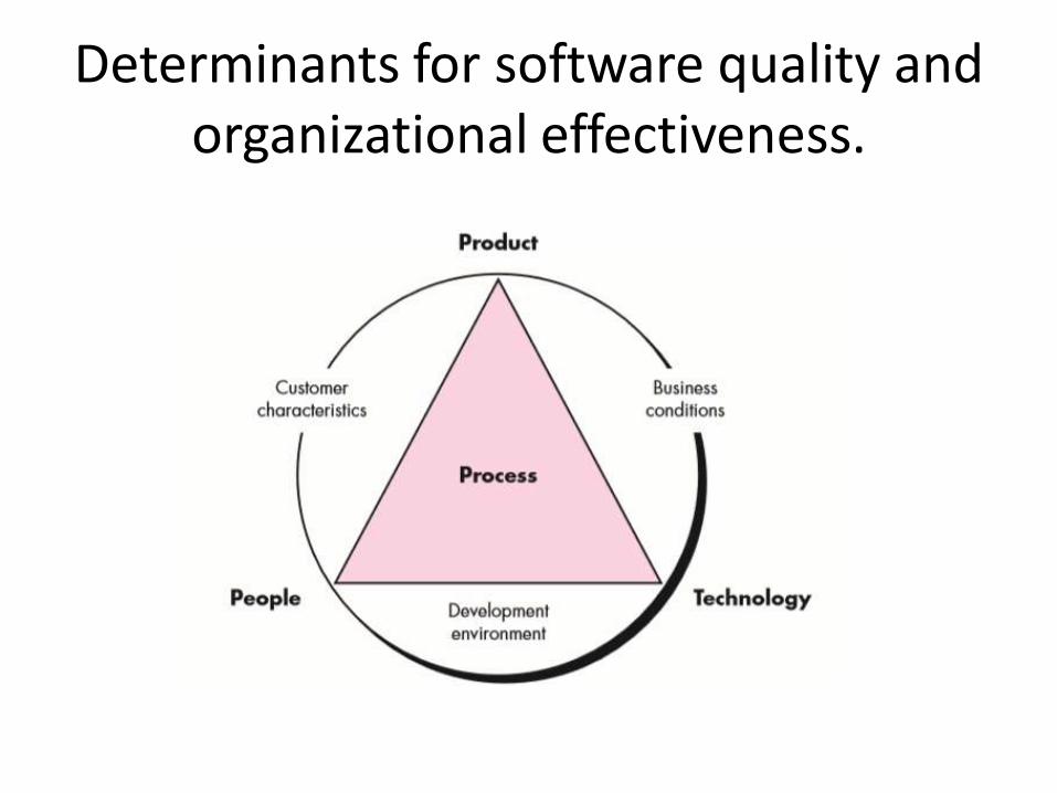
Determinants for software quality and organizational effectiveness.
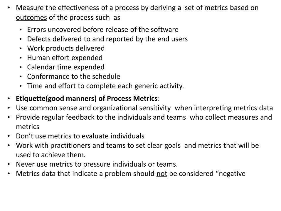
• Measure the effectiveness of a process by deriving a set of metrics based on
outcomes of the process such as
• Errors uncovered before release of the software• Defects delivered to and reported by the end users• Work products delivered• Human effort expended• Calendar time expended• Conformance to the schedule• Time and effort to complete each generic activity.
• Etiquette(good manners) of Process Metrics:• Use common sense and organizational sensitivity when interpreting metrics data• Provide regular feedback to the individuals and teams who collect measures and
metrics• Don’t use metrics to evaluate individuals• Work with practitioners and teams to set clear goals and metrics that will be
used to achieve them.• Never use metrics to pressure individuals or teams.• Metrics data that indicate a problem should not be considered “negative
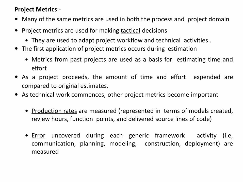
Project Metrics:-
Many of the same metrics are used in both the process and project domain
Project metrics are used for making tactical decisions
They are used to adapt project workflow and technical activities . The first application of project metrics occurs during estimation
Metrics from past projects are used as a basis for estimating time and
effort
As a project proceeds, the amount of time and effort expended are
compared to original estimates.
As technical work commences, other project metrics become important
Production rates are measured (represented in terms of models created,review hours, function points, and delivered source lines of code)
Error uncovered during each generic framework activity (i.e,communication, planning, modeling, construction, deployment) aremeasured
Project metrics are used to
Minimize the development schedule by making the adjustments necessary to
avoid delays and mitigate potential problems and risks
Assess product quality on an ongoing basis and, when necessary, to modify
the technical approach to improve quality
In summary
As quality improves, defects are minimized
As defects go down, the amount of rework required
during the project is also reduced
As rework goes down, the overall project cost is reduced
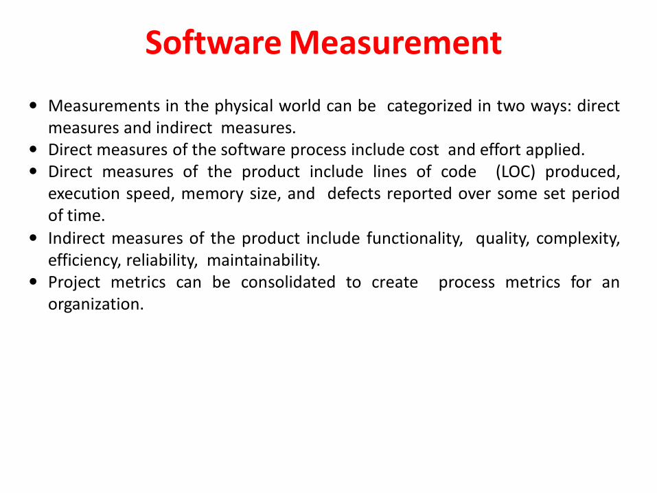
Measurements in the physical world can be categorized in two ways: directmeasures and indirect measures.
Direct measures of the software process include cost and effort applied. Direct measures of the product include lines of code (LOC) produced,
execution speed, memory size, and defects reported over some set periodof time.
Indirect measures of the product include functionality, quality, complexity,efficiency, reliability, maintainability.
Project metrics can be consolidated to create process metrics for anorganization.
Software Measurement
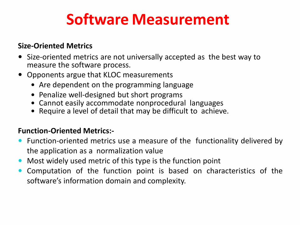
Size-Oriented Metrics
Size-oriented metrics are not universally accepted as the best way to measure the software process.
Opponents argue that KLOC measurements Are dependent on the programming language Penalize well-designed but short programs Cannot easily accommodate nonprocedural languages Require a level of detail that may be difficult to achieve.
Function-Oriented Metrics:- Function-oriented metrics use a measure of the functionality delivered by
the application as a normalization value Most widely used metric of this type is the function point Computation of the function point is based on characteristics of the
software’s information domain and complexity.
Software Measurement
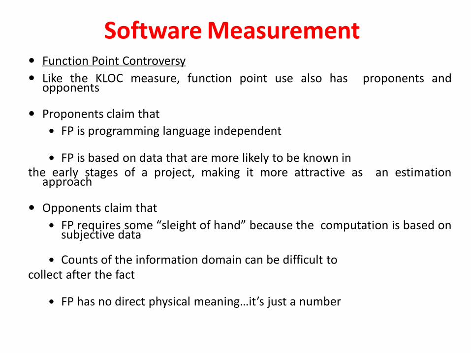
Function Point Controversy
Like the KLOC measure, function point use also has proponents andopponents
Proponents claim that
FP is programming language independent
FP is based on data that are more likely to be known inthe early stages of a project, making it more attractive as an estimation
approach
Opponents claim that
FP requires some “sleight of hand” because the computation is based onsubjective data
Counts of the information domain can be difficult tocollect after the fact
FP has no direct physical meaning…it’s just a number
Software Measurement
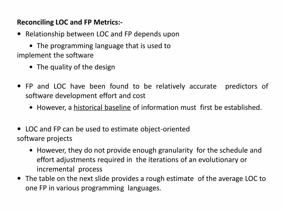
Reconciling LOC and FP Metrics:-
Relationship between LOC and FP depends upon
The programming language that is used toimplement the software
The quality of the design
FP and LOC have been found to be relatively accurate predictors ofsoftware development effort and cost
However, a historical baseline of information must first be established.
LOC and FP can be used to estimate object-orientedsoftware projects
However, they do not provide enough granularity for the schedule and effort adjustments required in the iterations of an evolutionary or incremental process
The table on the next slide provides a rough estimate of the average LOC to one FP in various programming languages.
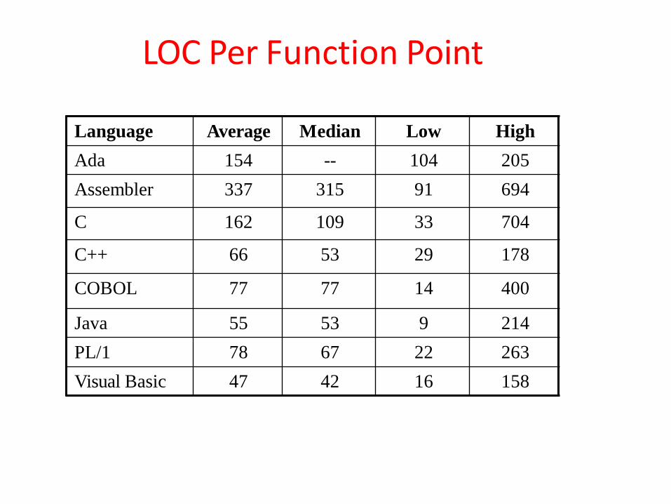
LOC Per Function Point
Language Average Median Low High
Ada 154 -- 104 205
Assembler 337 315 91 694
C 162 109 33 704
C++ 66 53 29 178
COBOL 77 77 14 400
Java 55 53 9 214
PL/1 78 67 22 263
Visual Basic 47 42 16 158
Object-oriented Metrics:-
Following set of metrics for OO projects:
Number of scenario scripts:- A scenario script is a detailed sequence of steps that describe the interaction between the user and the application.
Each script is organized into triplets of the form{initiator, action, participant} where initiator is the object that requests some service, action is the result
of the request, and participant is the server object that satisfies therequest.
Number of key classes.:- Key classes are the “highly independent components ” that are defined early in object-oriented analysis
Because key classes are central to the problem domain, the number of such classes is an indication of the amount of effort required to develop the software.
Also an indication of the potential amount of reuse to be applied during system development.
Number of support classes:- Support classes are required to implement the system but are not immediately related to the problem domain.
• The number of support classes is an indication of the amount of effortrequired to develop the software and also an indication of the potentialamount of reuse to be applied during system development.
• Number of subsystems• A subsystem is an aggregation of classes that support a function that is
visible to the end user of a system.
Average number of support classes per key class Key classes are identified early in a project (e.g., at requirements
analysis) Estimation of the number of support classes can be made from the
number of key classes
GUI applications have between two and three times more support
classes as key classes
Non-GUI applications have between one and two times more support
classes as key classes
Use-Case–Oriented Metrics:-
Use cases describe user-visible functions and features that are basicrequirements for a system.
The number of use cases is directly proportional to the size of the applicationin LOC and to the number of test cases that will have to be designed to fullyexercise the application.
WebApp Project Metrics:-
The objective of all WebApp projects is to deliver a combination of content and
functionality to the end user.
The measures that can be collected are:
• Number of static Web pages.• Number of dynamic Web pages.• Number of internal page links.:-Internal page links are pointers that provide a
hyperlink to some other Web page within the WebApp
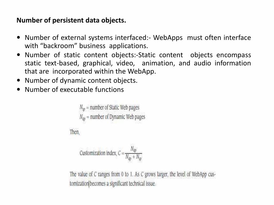
Number of persistent data objects.
Number of external systems interfaced:- WebApps must often interfacewith “backroom” business applications.
Number of static content objects:-Static content objects encompassstatic text-based, graphical, video, animation, and audio informationthat are incorporated within the WebApp.
Number of dynamic content objects. Number of executable functions
The overriding goal of software engineering is to produce a high-quality system,application, or product within a time frame that satisfies a market need.
The quality of a system, application, or product is only as good as therequirements that describe the problem, the design that models the solution,the code that leads to an executable program, and the tests that exercise thesoftware to uncover errors.
Measuring Quality
• There are many measures of software quality,8 correctness, maintainability,integrity, and usability provide useful indicators for the project team
Correctness:
• Correctness is the degree to which the software performs its required function.• The most common measure for correctness is defects per KLOC, where a defect
is defined as a verified lack of conformance to requirements.• Defects are those problems reported by a user of the program after the
program has been released for general use.
Metrics For Software Quality

Maintainability:
• Maintainability is the ease with which a program can be corrected if anerror is encountered, adapted if its environment changes, or enhancedif the customer desires a change in requirements.
• Mean -time-to-change (MTTC), the time it takes to analyze the changerequest, design an appropriate modification, implement the change,test it, and distribute the change to all users.
• Integrity:
• Software integrity has become increasingly important in the age of cyber terrorists and hackers.
• Attacks can be made on all three components of software: programs, data, and documentation.
• To measure integrity, two attributes must be defined:• threat and security.
• Usability:• If a program is not easy to use, it is often doomed to failure, even if the
functions that it performs are valuable
Defect Removal Efficiency:
Defect removal efficiency provides benefits at both the project and process level
It is a measure of the filtering ability of quality assurances activities as they are
applied throughout all process framework activities
It indicates the percentage of software errors found before software release
It is defined as DRE = E / (E + D)
E is the number of errors found before delivery of the software to the end
user
D is the number of defects found after delivery
• As D increases, DRE decreases (i.e., becomes a smaller and smaller fraction)
• The ideal value of DRE is 1, which means no defects are found after delivery
• DRE encourages a software team to institute techniques for finding as many
errors as possible before delivery.
Arguments for Software Metrics:-
• Most software developers do not measure, and most have little desire to begin
• Establishing a successful company-wide software metrics program can be a multi-year effort
• But if we do not measure, there is no real way of determining whether we are improving
• Measurement is used to establish a process baseline from which improvements can be assessed
• Software metrics help people to develop better project estimates, produce higher-quality systems, and get products out the door on time.
• The collection of quality metrics enables an organization to “tune” its software process to remove the “vital few” causes of defects that have the greatest impact on software development
Integrating Metrics Within The Software Process
Establishing a Baseline:-• By establishing a metrics baseline, benefits can be obtained at the software
process, product, and project levels
• The same metrics can serve many masters
• The baseline consists of data collected from past software development projects.
Baseline data must have the following attributes Data must be reasonably accurate (guesses should be avoided) Data should be collected for as many projects as
possible Measures must be consistent (e.g., a line of code must be interpreted
consistently across all projects) Past applications should be similar to the work that is to be estimated.
Metrics Collection, Computation, and Evaluation• Data collection requires an historical investigation of past projects to
reconstruct required data• After data is collected and metrics are computed, the metrics should be
evaluated and applied during estimation, technical work, project control, and process improvement.
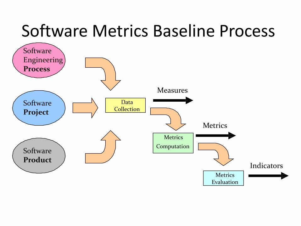
Software Metrics Baseline ProcessSoftware Engineering Process
SoftwareProject
SoftwareProduct
Data Collection
Metrics
Computation
Metrics Evaluation
Measures
Metrics
Indicators
• Most software organizations have fewer than 20 software engineers.
• It is reasonable to suggest that software organizations of all sizes measure andthen use the resultant metrics to help improve their local software process andthe quality and timeliness of the products they produce.
• A commonsense approach to the implementation of any software process-relatedactivity is: keep it simple, customize to meet local needs, and be sure it addsvalue.
A small organization might select the following set of easily collected measures:
• Time (hours or days) elapsed from the time a request is made until evaluation iscomplete, tqueue.
• Effort (person-hours) to perform the evaluation, Weval.
• Time (hours or days) elapsed from completion of evaluation to assignment ofchange order to personnel, teval.
Metrics For Small Organizations
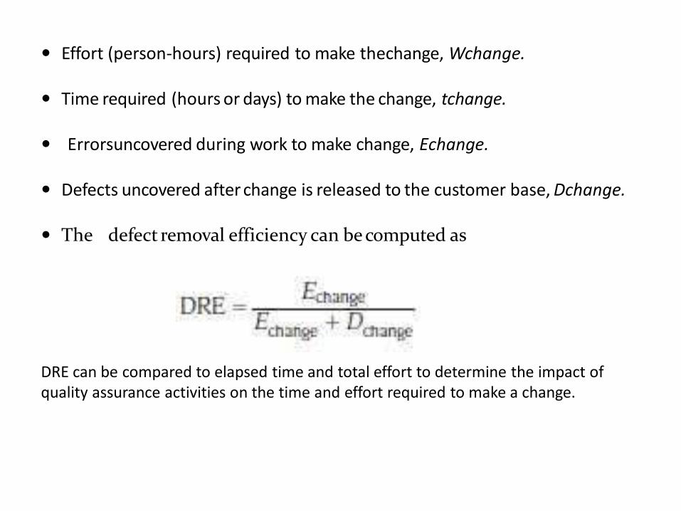
Effort (person-hours) required to make thechange, Wchange.
Time required (hours or days) to make the change, tchange.
Errorsuncovered during work to make change, Echange.
Defects uncovered after change is released to the customer base, Dchange.
The defect removal efficiency can be computed as
DRE can be compared to elapsed time and total effort to determine the impact of quality assurance activities on the time and effort required to make a change.
The Software Engineering Institute has developed a comprehensive guidebook forestablishing a “goal-driven” software metrics program.
The guidebook suggests the following steps:
• Identify business goal
• Identify what you want to know
• Identify subgoals
• Identify subgoal entities and attributes
• Formalize measurement goals
• Identify quantifiable questions and indicators related to subgoals
• Identify data elements needed to be collected to construct the indicators
• Define measures to be used and create operational definitions for them
• Identify actions needed to implement the measures
• Prepare a plan to implement the measures
Establishing a software metrics program
Establishing a software metrics program• For example, consider the SafeHome product. Working as a team,
software engineering and business managers develop a list of prioritizedbusiness goals:
1. Improve our customers’ satisfaction with our products.
2. Make our products easier to use.
3. Reduce the time it takes us to get a new product to market.
4. Make support for our products easier.
5. Improve our overall profitability.


![Software Effort Estimation Inspired by COCOMO …...Extensions of COCOMO, such as COMCOMO II, can be found [25], however, for the purpose of research reported, in this paper, the basic](https://static.fdocuments.us/doc/165x107/5f0bd3f17e708231d432692e/software-effort-estimation-inspired-by-cocomo-extensions-of-cocomo-such-as.jpg)


![A Variant of COCOMO II for Improved Software Effort Estimation · COCOMO 81 (Constructive Cost Model) is an empirical estimation scheme proposed in 1981 [23], [24] as a model for](https://static.fdocuments.us/doc/165x107/5e5707bda1def618bb1a541d/a-variant-of-cocomo-ii-for-improved-software-effort-cocomo-81-constructive-cost.jpg)