SOFTWARE ENGINEERING for REAL-TIME SYSTEMS (© J.E.Cooling 2003) Requirements - slide 1 Software...
45
SOFTWARE ENGINEERING for REAL-TIME SYSTEMS (© J.E.Cooling 2003) Requirements - slide 1 Software engineering for real-time systems Section 3 Requirements analysis and specification
-
Upload
april-wilson -
Category
Documents
-
view
214 -
download
1
Transcript of SOFTWARE ENGINEERING for REAL-TIME SYSTEMS (© J.E.Cooling 2003) Requirements - slide 1 Software...

SOFTWARE ENGINEERING for REAL-TIME SYSTEMS (© J.E.Cooling 2003) Requirements - slide 1
Software engineering for real-time systems
Section 3
Requirements analysis and specification

SOFTWARE ENGINEERING for REAL-TIME SYSTEMS (© J.E.Cooling 2003) Requirements - slide 2
Objectives
To: Distinguish between mythical and realistic software life cycle models.
Show where requirements analysis and software specification (the requirements stage) fits into the life cycle.
Highlight the importance of the requirements stage.
Introduce the topic of software prototyping.
Introduction
From system requirements to software specifications

SOFTWARE ENGINEERING for REAL-TIME SYSTEMS (© J.E.Cooling 2003) Requirements - slide 3
The software life cycle
The software life cycle
-
From problem to solution

SOFTWARE ENGINEERING for REAL-TIME SYSTEMS (© J.E.Cooling 2003) Requirements - slide 4
User problem
Problem analysis
Requirement specification
Architectural design
Physical design
Implementation
Test and debug
Maintain
Customers requirements
System requirements
Software requirements specification
Software structure
Hardware/Software structure
Software modules
Total software package
Statement of requirements
The mythical software life cycle

SOFTWARE ENGINEERING for REAL-TIME SYSTEMS (© J.E.Cooling 2003) Requirements - slide 5
Analysis andspecification
Design ImplementationTest and
debug
Time
Effort
Project effort distribution - another myth

SOFTWARE ENGINEERING for REAL-TIME SYSTEMS (© J.E.Cooling 2003) Requirements - slide 6
Need perceived
Informal specification
Informal discussions with suppliers
Formal tendering specification
Bid analysis
Reply by suppliers
Modification of tendering specification
Contract awarded - SOR
Formulating the user statement of requirements (SOR)

SOFTWARE ENGINEERING for REAL-TIME SYSTEMS (© J.E.Cooling 2003) Requirements - slide 7
User problem
Problem analysis
Requirement specification
Architectural design
Physical design
Implementation
Test and debug
Maintain
Customers requirements
System requirements
Software requirements specification
Software structure
Hardware/Software structure
Software modules
Total software package
Statement of requirements
A more realistic software life-cycle model

SOFTWARE ENGINEERING for REAL-TIME SYSTEMS (© J.E.Cooling 2003) Requirements - slide 8
PROJECTRequirements
and designImplementation Test, debug
and integrationSAGE 39 14 47NTDS 30 20 50GEMINI 36 17 47SATURN V 32 24 44OS/360 33 17 50TRW Survey 46 20 34
Distribution of software effort

SOFTWARE ENGINEERING for REAL-TIME SYSTEMS (© J.E.Cooling 2003) Requirements - slide 9
Analysis andspecification
Design
Test integration anddebug
Effort
Time
Implementation
Project effort distribution - reality

SOFTWARE ENGINEERING for REAL-TIME SYSTEMS (© J.E.Cooling 2003) Requirements - slide 10
D efence S taff;D efence procurem entagenc ies
A nalys is and des igne.g.A nalys is o f the a ir warfare threat.O vera ll des ign of appropria te a ir in terceptor fightersys tem .
O utput: O vera ll system S O R .
M ain contractor:the a irc raft m anufacturer.
A nalys is o f system requirem ents andits overa ll des ign.D esign o f the weapon av ionics (N A V /W A S ) sub-system .E laboration o f system spec ifications.
O utput: S ub-system spec ifications.
A nalys is o f the N A V /W A S sub-systemspecifications.D esign o f the sub-systemO utput: N A V /W A S system , hardware and software
spec ifications.
A v ion ics (N A V /W A S )
software developer
O utput: D es ign docum entation andsource code.
Floor
Floor
Floor
Ceiling
Ceiling
Ceiling
A vionics (N A V /W A S )subcontractor
A nalys is o f the problem -A ir defence requirem ents--------------------------------------
A nalys is o f system and software spec ifications.D esign o f the software.
The development process - a layered approach

SOFTWARE ENGINEERING for REAL-TIME SYSTEMS (© J.E.Cooling 2003) Requirements - slide 11
D ESIG N SP ECIF IC ATIO N -C O M PLETEN ESS AN D
C O M PR EH EN SIO N
D ESIGNSO LU TIO N
CO N C EPTU ALSO FTW A RE
* Evaluation* Deve lopm ent
o f C onceptsD esign
Im plem enta tionR eview
Tim e
Start
C O D E
Incremental development of software

SOFTWARE ENGINEERING for REAL-TIME SYSTEMS (© J.E.Cooling 2003) Requirements - slide 12
The importance of requirements capture
The importance of requirements capture
-
Mistakes and their consequences

SOFTWARE ENGINEERING for REAL-TIME SYSTEMS (© J.E.Cooling 2003) Requirements - slide 13
Making mistakes

SOFTWARE ENGINEERING for REAL-TIME SYSTEMS (© J.E.Cooling 2003) Requirements - slide 14
Requirem ents56%
Code7% Other10%
Design27%
Sources of software errors

SOFTWARE ENGINEERING for REAL-TIME SYSTEMS (© J.E.Cooling 2003) Requirements - slide 15
Requirem ents 82%
Other 4%Code 1%
Design 13%
Cost of rectifying software errors

SOFTWARE ENGINEERING for REAL-TIME SYSTEMS (© J.E.Cooling 2003) Requirements - slide 16
The impact of requirements errors
Requirem ents 82%
Other 4%Code 1%
Design 13%
Requirem ents56%
Code7% O ther10%
Design27%
Error source No. of errors
Correction cost
Overall impact
Percentage impact
Requirements 56 0.82 45.92 85
Design 27 0.13 0.13 6.5
Coding 7 0.1 0.7 1.2
Other 10 0.4 4.0 7.4
For every 100 errors
SOFTWARE ENGINEERING for REAL-TIME SYSTEMS (© J.E.Cooling 2003) Requirements - slide 17
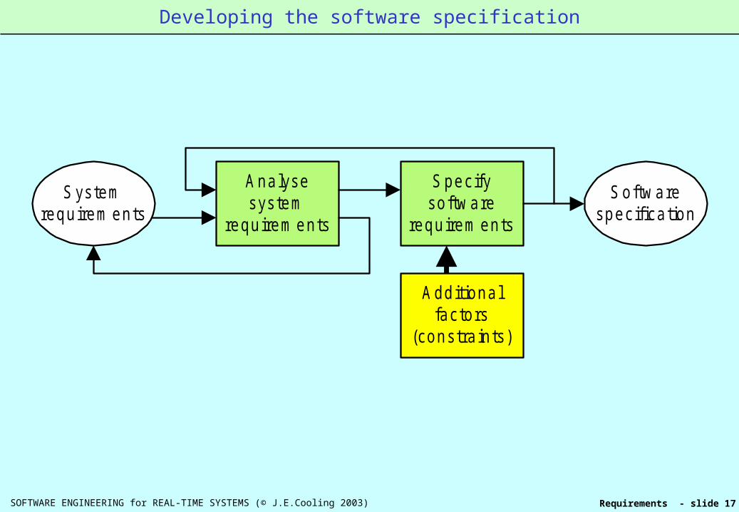
Systemrequirem ents
Analysesystem
requirem ents
Specifysoftware
requirem ents
Additionalfactors
(constraints)
Softwarespecification
Developing the software specification

SOFTWARE ENGINEERING for REAL-TIME SYSTEMS (© J.E.Cooling 2003) Requirements - slide 18
Overall system description
What it'ssupposed to do
Function
How well itmust do it
Performance
How it fits in withits environment
Interfaces
Do's anddon’t's
Constraints
"Real world" interfaces "Software world" interfaces
Man-machine Plant Operatingsystems
Databases
Overall system description

SOFTWARE ENGINEERING for REAL-TIME SYSTEMS (© J.E.Cooling 2003) Requirements - slide 19
Requirem ents specification
Functionalrequirem ents
Non-functionalrequirem ents
Developm entrequirem ents
W hat it does:Behaviour
W hat it has:A ttributes
How it shouldbe built
Software specification features

SOFTWARE ENGINEERING for REAL-TIME SYSTEMS (© J.E.Cooling 2003) Requirements - slide 20
The originalrequirem ents
The deliveredproduct
Errors in translation
Form ulation ofrequirem ents
Com m unication ofrequirem ents
Change torequirem ents
Understandingof requirem ents
Determ ined byuser expertise
Determ ined by them ethods used
Determ ined bythe suppliers
expertise
Unpredictable
Where mistakes are made in defining requirements

SOFTWARE ENGINEERING for REAL-TIME SYSTEMS (© J.E.Cooling 2003) Requirements - slide 21
Practical requirements capture methods
Defining system requirements
-Practical requirements capture methods:
1. Use cases. 2. Prototyping.

SOFTWARE ENGINEERING for REAL-TIME SYSTEMS (© J.E.Cooling 2003) Requirements - slide 22
Use Case Fundamentals
Use case fundamentals
Use Cases are a technique for organizing and presenting requirements.
They can be used to:
Analyse clients requirements.
Minimize confusion and misunderstanding between clients and suppliers.
Validate system-level designs.
Develop specifications for the software system itself.
Define the outlines of system acceptance tests.

SOFTWARE ENGINEERING for REAL-TIME SYSTEMS (© J.E.Cooling 2003) Requirements - slide 23
Library
Bookshop
Bank
• The starting point:
• System requirements are related to the whats, whens and hows of system usage.
• People are USERS of systems.
• Systems are also users of systems.
Setting the scene

SOFTWARE ENGINEERING for REAL-TIME SYSTEMS (© J.E.Cooling 2003) Requirements - slide 24
John
Jim
Alex
Bookshop
Library
• Many people.
• Many systems.
• Exactly why are people using the system?
• What are we interested in?
Systems and their users

SOFTWARE ENGINEERING for REAL-TIME SYSTEMS (© J.E.Cooling 2003) Requirements - slide 25
Order book
John
Jim
CustomerBookshop
Order book
(a) (b)
The system of concern is a bookshop.
There are two users (specifically two individuals).
The individuals are using the system to order a book (orbooks).
Any illustration of the use of a system is defined to be a ‘usecase’; hence this example is the use case ‘order book’.
‘Roles’ - both people are ‘customers’.
Basics of the use case diagram

SOFTWARE ENGINEERING for REAL-TIME SYSTEMS (© J.E.Cooling 2003) Requirements - slide 26
Order Book
Diagram symbol(icon)
"The customer places a telephoneorder for a book. It will be
dispatched within 24 hours"
Text description
What goes on when a customer tries to order a book?
•The diagram symbol for a use case is an ellipse. •Inside this is written the name of the use case.
•But this doesn’t give any detail of the use case.
•Thus a description of the use case must be provided.
The components of a use case

SOFTWARE ENGINEERING for REAL-TIME SYSTEMS (© J.E.Cooling 2003) Requirements - slide 27
Actors
Use Case 1
Use Case 2
Use Case 3
Use cases
Text for use case 1
Text for use case 2
Text for use case 3
Use case descriptions
Each system has its own use case model
•This model consists of actors, use cases and use case descriptions.
• Actors depict the ‘roles’ performed by users.
• The reasons why actors use the system are shown as a set of use cases.
• Use case descriptions add detail.
The components of the use case model

SOFTWARE ENGINEERING for REAL-TIME SYSTEMS (© J.E.Cooling 2003) Requirements - slide 28
Navigator
Pilot
Nav/Was system Air data system
Get NavigationWaypoints
Set AirfieldAltitude
Navigator
Pilot
(a) (b)
Each system is drawn as a rectangular box.
The relevant use cases are shown as ellipses inside them.
Outside the system boundary are the actors.
These are connected to (‘associated with’) the use cases using by drawing lines between them.
Example use case diagrams

SOFTWARE ENGINEERING for REAL-TIME SYSTEMS (© J.E.Cooling 2003) Requirements - slide 29
The navigator enters new valuesfor the airfield altitude.This is displayed on the pilot'shead-down display
START
1. Navigator enters airfield altitude data.
2. System checks data range validity.
3. New values displayed to the navigator. Conformation required
4. Navigator confirms values.
5. New values displayed on pilot's head-down display. FINISH
(a) Initial
(b) Expanded
Describing and structuring use cases
Use cases: text description

SOFTWARE ENGINEERING for REAL-TIME SYSTEMS (© J.E.Cooling 2003) Requirements - slide 30
Types of scenarios
Normal (error-free) use of the system.
Uses where errors occur but which can be dealtwith as part of the interaction process (e.g.entering invalid data).
Uses where errors occur but which cannot bedealt with as part of the normal processing(exceptions).
Use case scenarios
‘A particular sequence of interactions’
Use case scenarios

SOFTWARE ENGINEERING for REAL-TIME SYSTEMS (© J.E.Cooling 2003) Requirements - slide 31
• Both scenarios apply to the same use case.
• In practice a use case could have a number of scenarios.
• As the paperwork expands it becomes more difficult to apply use case techniques effectively.
Scenarios - text descriptions
(b) Scenario 2 - Data not in valid range
Start 1. Navigator enters ___
2. System checks data range validity. 2.1 System rejects data. 2.2 Requests re-entry of data. 2.3 Go to action 1.
3. New values _ _ _ 4. Navigator confirms_ _ _ 5. New values _ _ _
Finish
(a) Scenario 1 - Data within valid range
Start
1. Navigator enters airfield altitude data.
2. System checks data range validity.
3. New values displayed to the navigator. Conformation required
4. Navigator confirms values.
5. New values displayed on pilot's head-down display.
Finish

SOFTWARE ENGINEERING for REAL-TIME SYSTEMS (© J.E.Cooling 2003) Requirements - slide 32
Combining scenarios
Start 1. Navigator _ _ _
2. System checks input data.
3. New _ _ _ 4. Navigator _ _ _ 5. New _ _ _ Finish
Start1. System checks data range validity. 2. IF in range THEN 2.1 System acknowledges entry. ELSE 2.2 System rejects data. Requests re-entry of data. Navigator enters data Go to action 1.Finish
Simplifying the paperwork - combine the individual scenarios
Presentation style 1
Presentation style 2
A ‘mini’ use case description
Start 1. Navigator _ _ _ 2. System checks data range validity. IF in range THEN 2.1 System acknowledges entry. ELSE 2.2 System rejects data. Requests re-entry of data. Navigator enters data. Go to action 2. 3. New _ _ _ 4. Navigator _ _ _ 5. New _ _ _
Finish

SOFTWARE ENGINEERING for REAL-TIME SYSTEMS (© J.E.Cooling 2003) Requirements - slide 33
Navigator Air data system
Set Airfield Altitude
Validate Data Range
<< Include >>
Pilot
Use case diagram for previous slide - the include relationship
The separate text can be treated as a use case in its own right
The include relationship

SOFTWARE ENGINEERING for REAL-TIME SYSTEMS (© J.E.Cooling 2003) Requirements - slide 34
Variations on a theme
1. A base use case may be complete but
2. There may be situations where extra operationsare required
3. In this situation the functionality of the base usecase is extended by a second one.
The extend relationship

SOFTWARE ENGINEERING for REAL-TIME SYSTEMS (© J.E.Cooling 2003) Requirements - slide 35
Air Electronics Officer Generating system
Check Alarm Status
Set Alarm Limits
<< extend >>
• The base use case - ‘Check Alarm Status’ - is complete.
• It describes what happens when the AEO checks out the generating system alarms.
• Most of the time this is the only action required.
• However, sometimes it may be necessary to set the alarm limits.
• Thus extra functions must be performed.
• These are defined in the use case ‘Set Alarm Limits’.
The extend relationship (more)

SOFTWARE ENGINEERING for REAL-TIME SYSTEMS (© J.E.Cooling 2003) Requirements - slide 36
The distinction between includes and extends.
Include use cases collect in one place behaviour which is : Either called on a number of times within one use case
and/or Is common to a number of base use cases (fig. (a)).
Extend use cases show variations on a theme (fig. (b)).
Set airfieldaltitude
Set autopilotmode
Validatedata range
<<Include>>
<<Include>>
Check alarmstatus
Maintaingeneratingsystems
Set alarmlimits
<<Extend>>
<<Extend>>
(b)(a)
Comparing the include and extend relationships

SOFTWARE ENGINEERING for REAL-TIME SYSTEMS (© J.E.Cooling 2003) Requirements - slide 37
Up to this point we have used actors to representthe roles of people.
But frequently systems interact, not only withpeople, but with other systems.
Navigator
P ilot Nav/W assystem
Air datasystem
(a) System view
Nav/W assystem
Air datasystem
(b) Use case view
External systems as actors

SOFTWARE ENGINEERING for REAL-TIME SYSTEMS (© J.E.Cooling 2003) Requirements - slide 38
Introduction to protoyping
Prototyping withinthe
software life cycle

SOFTWARE ENGINEERING for REAL-TIME SYSTEMS (© J.E.Cooling 2003) Requirements - slide 39
Exploratory prototyping
Solution prototyping
Investigative prototyping
Verification prototyping
Evolutionary prototyping
Form al tendering specification
Reply by supplier
SOR
Requirem entsphases
Design phases
Build andm aintenance
phases
Prototyping within the software life cycle

SOFTWARE ENGINEERING for REAL-TIME SYSTEMS (© J.E.Cooling 2003) Requirements - slide 40
Prototypingtool
User interfaceOutputsupportsystem
Designm anagem ent
Design toolsDesign
database
Modellingenvironm ent
Elements of a prototyping tool

SOFTWARE ENGINEERING for REAL-TIME SYSTEMS (© J.E.Cooling 2003) Requirements - slide 41
Screen prototype proposed avionics cockpit instrument layout

SOFTWARE ENGINEERING for REAL-TIME SYSTEMS (© J.E.Cooling 2003) Requirements - slide 42
Anim ationscreendisplaym odel
Model properties
Anim ation engine
User
Building the animation model

SOFTWARE ENGINEERING for REAL-TIME SYSTEMS (© J.E.Cooling 2003) Requirements - slide 43
Screenm odel
buildingtool
Behavioural/tem poralm odel building tool
Screen m odel
Graphical(com ponent)
libraries
Behavioural/tem poral m odel
Lin
kM O DEL INPUTS Devices (com ponents) Device attributes Tim ing inform ation Stim uli (events) Com ponent
connections
M O DEL INPUTS Functions and
dynam ics
Animation prototyping typical development environment
SOFTWARE ENGINEERING for REAL-TIME SYSTEMS (© J.E.Cooling 2003) Requirements - slide 44
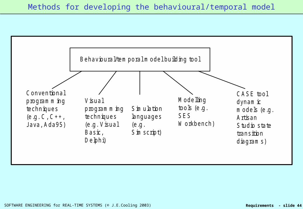
Behavioural/tem poral m odel building tool
Conventionalprogram m ingtechniques(e.g. C, C++,Java, Ada95)
V isualprogram m ingtechniques(e.g. V isualBasic,Delphi)
S im ulationlanguages(e.g.S im script)
Modellingtools (e.g.SESW orkbench)
CASE tooldynam icm odels (e.g.ArtisanStudio statetransitiondiagram s)
Methods for developing the behavioural/temporal model

SOFTWARE ENGINEERING for REAL-TIME SYSTEMS (© J.E.Cooling 2003) Requirements - slide 45
Review of section
You should now:
Be able to explain the realistic development of software in real-time systems.
Appreciate how important it is to properly and fully establish the true requirements of systems before plunging into design.
Understand the basics of use case analysis techniques.
Understand the basic role of prototyping in establishing system requirements.
Appreciate how rapid and animation prototyping can be used effectively as front-end techniques in defining system and software requirements.
END OF SECTION ‘Requirements analysis and specification’
Review of ‘Requirements analysis and specification’