SOFTWARE DESIGN DESCRIPTIONuser.ceng.metu.edu.tr/~e1746221/docs/SDDv1.1.pdf · Leş Koding Baran...
65
2013 Leş Koding Baran KÜÇÜKGÜZEL Batuhan TAŞDÖVEN Ali Barış UZUNER Bekir ÖZTÜRK SOFTWARE DESIGN DESCRIPTION This document is prepared by Leş Koding’s members; the document is about software design description of the project “Science Wars”.
Transcript of SOFTWARE DESIGN DESCRIPTIONuser.ceng.metu.edu.tr/~e1746221/docs/SDDv1.1.pdf · Leş Koding Baran...

2013
Leş Koding Baran KÜÇÜKGÜZEL Batuhan TAŞDÖVEN Ali Barış UZUNER Bekir ÖZTÜRK
SOFTWARE DESIGN DESCRIPTION This document is prepared by Leş Koding’s members; the document is about software design description of the project “Science Wars”.
1
PREFACE
This Document contains the system design information about Science Wars project. This
document is prepared according to the “IEEE Standard for Information Technology – Systems Design –
Software Design Descriptions – IEEE Std 1016 – 2009”. This Software Design Documentation provides a
complete description of all the system design and views of the Project on both client and server side
applications. The first section of this document includes Project Identification, Stakeholders
Identification and requirements, Composition of the developers’ team. The following sections include
document purpose and design viewpoints of the system.
2
Table of Contents PREFACE ........................................................................................................................................................ 1
1. Overview ................................................................................................................................................... 5
1.1 Scope ................................................................................................................................................... 5
1.2 Purpose ............................................................................................................................................... 5
1.3 Intended Audience .............................................................................................................................. 5
2. Definitions ................................................................................................................................................. 5
3. Conceptual model for software design descriptions ................................................................................ 7
3.1 Software design in context ................................................................................................................. 7
3.2 Software Design Descriptions within Life Cycle .................................................................................. 7
3.2.1 Influences on SDD Preparation .................................................................................................... 7
3.2.2 Influences on Software Life Cycle Products ................................................................................. 7
3.2.3 Design Verification and Design Role in Validation ....................................................................... 7
4. Design Description Information Content .................................................................................................. 8
4.1 Introduction ........................................................................................................................................ 8
4.2 SDD identification ............................................................................................................................... 8
4.3 Design Stakeholders and Their Concerns............................................................................................ 8
4.4 Design Views ....................................................................................................................................... 8
4.5 Design Viewpoints ............................................................................................................................... 9
4.6 Design Rationale ................................................................................................................................. 9
4.7 Design Languages ................................................................................................................................ 9
5. Design Viewpoints ..................................................................................................................................... 9
5.1 Introduction ........................................................................................................................................ 9
5.2 Context viewpoint ............................................................................................................................. 10
5.2.1 Log in Screen .............................................................................................................................. 10
5.2.2 Lobby Screen .............................................................................................................................. 11
5.2.3 Game Screen .............................................................................................................................. 12
5.3 Logical viewpoint .............................................................................................................................. 13
5.3.1 Design elements ......................................................................................................................... 13
5.4 Dependency viewpoint ..................................................................................................................... 47
5.4.1 Design elements ......................................................................................................................... 48
5.4.2 Subsystem Connections ............................................................................................................. 50
3
5.5 Information viewpoint ...................................................................................................................... 51
5.6 Interaction viewpoint ........................................................................................................................ 53
5.6.1 Design concerns ......................................................................................................................... 53
5.6.2 Design elements ......................................................................................................................... 53
5.6.3 Login Interaction ........................................................................................................................ 53
5.7 State dynamics viewpoint ................................................................................................................. 61
6 Estimated Schedule .................................................................................................................................. 63
7 Conclusion ................................................................................................................................................ 64
4
Figure 1 Login Screen Use Case Diagram .................................................................................................... 10
Figure 2 Lobby Screen Use Case Diagram ................................................................................................... 11
Figure 3 Game Screen Use Case Diagram ................................................................................................... 12
Figure 4 Modules of the project ................................................................................................................. 48
Figure 5 Illustration of the network communication .................................................................................. 51
Figure 6 Database tables ............................................................................................................................. 51
Figure 7 Login Interaction ........................................................................................................................... 53
Figure 8 EnterQueue Interaction ................................................................................................................ 54
Figure 9 Match Found Interaction .............................................................................................................. 55
Figure 10 Build Tower Interaction .............................................................................................................. 56
Figure 11 Spawn Minion Interaction........................................................................................................... 57
Figure 12 Upgrade Tower Interaction ......................................................................................................... 58
Figure 13 Upgrade Minion Interaction ....................................................................................................... 59
Figure 14 Use Skill Interaction .................................................................................................................... 60
Figure 15 State Diagram of the Client ......................................................................................................... 61
Figure 16 Estimated schedule of the project .............................................................................................. 63

5
1. Overview
The Software Design Document gives information about how the software should be build.
Details of the system are represented using graphical notations like: use case models, class diagrams,
sequence diagrams etc.
1.1 Scope
In this document all components of the system and a detailed design of each model are
explained. There will be some set of design views which will help the process of developing and
understanding the project. This documentation is the guideline for the implementation.
1.2 Purpose
This document aims to describe the both Client and Server side software of the Science Wars
project with the help of several viewpoints. This document is to primary reference to the
implementation phase. This document describes the system so that the system fills the needs described
in the SRS document.
1.3 Intended Audience
The intended audience for this document is both stakeholders and the developers.
2. Definitions
IEEE: Institute of Electrical and Electronics Engineers.
GUI: Graphical user interface.
DAO: Data Access Object
Science Wars: Permanent name of the game.
SVN: Subversion repository.
TortoiseSVN: The program we used for revision control.
Unity3D: Game engine we used for client side.

6
Visual Studio: A platform we used for implement server.
MySQL: Open-source relational database management system.
Session: A class for people connected to game before log in.
User: A class for people after log in.
Player: A class for user after joins a game.
Board: Part of map which belongs to one player in game.
Game: A class creating after start a game and keep all informations about it.
Minion: Soldiers a player can use for attack his opponents.
Tower: Buildings a player can use for defense from his opponents.
Missile: Bullets used by towers for attack to minions.
Message: Objects we used for communications between server and client.
Lobby: A place for all players in after log in.
Queue: A line where players wait for us to find suitable opponents for them.
Skill: Some special talents a player can use in game.
Science Tree: An upgrade tree every player has and unlocks new features for game.
SOLID: Single responsibility, Open-closed, Liskov substitution, Interface segregation and
Dependency inversion
Elo: The Elo rating system is a method for calculating the relative skill levels of players in such
competitor-versus-competitor games such as chess, LOL and so on.
7
3. Conceptual model for software design descriptions
3.1 Software design in context
This project will be designed as object –oriented in a modular design fashion. In this structure, it
can respond to users’ demands quickly and efficiently. Since it is a multiplayer-real time game, this
property is critically important. With modularity and adaptability, new game modes and different
towers, minions, skills can easily be added to the game.
3.2 Software Design Descriptions within Life Cycle
3.2.1 Influences on SDD Preparation
This document is prepared by considering the opinions of the stakeholders and the SRS
document is an important reference to this document.
3.2.2 Influences on Software Life Cycle Products
This project is a client-server application. All of the game steps are going to be simulated and
calculated on the server and the clients (users) will be informed via the network module of the game.
Hence the most important concepts in this project is the network module and the server module. We
should make these components available as soon as possible so we could get feedback from the
stakeholders. Then the development of the client side will be easier. Moreover we are going to have
multiple client applications like desktop application, android tablet application etc. , so first of all the
server-side should be available as soon as possible then we can continue on developing multiple client
applications.
3.2.3 Design Verification and Design Role in Validation
Since Science Wars is a multiplayer real-time strategy game, the server is responsible of making
calculation of every game simultaneously and there is a definite time period of calculation of each game
state. The server is responsible of calculating game progress in given time and sending related
information to the clients for the sake of real-time game concept. The server and network modules
should be reliable, stable and scalable. The client module is responsible for the listening for user
commands and sending them to the server for processing then listening related information from the
server module. Another important responsibility of the client is to show the game progress visually to

8
the users. Therefore we should test our design and overall system constantly throughout the
development progress.
4. Design Description Information Content
4.1 Introduction
This part of the Software Design Document is aiming to provide information about how the
design description will be explained in the later parts of this document. In this section we will give
information about SDD identification, identified design stakeholders Identified design concerns, selected
design viewpoints, each with type definitions of its allowed design elements and design languages,
design view, design overlays ,design rationale.
4.2 SDD identification
This is the initial SDD for the project Science Wars of the team Leş Koding. The date of issue for
this document is: 29.11.2013. This is not the final design document for the project Science Wars and is
subject to change in future. The issuing organization for this document is team Leş Koding which is
established by Ali Barış Uzuner, Baran Küçükgüzel, Bekir Öztürk, Batuhan Taşdöven. The supervisors of
this project are Dr. Selim Temizer and Asst. Serdar Çiftçi. The scope of this document is the software
design information about the project Science Wars. In this design report we will mainly use UML for
explaining the design viewpoints.
4.3 Design Stakeholders and Their Concerns
The design stakeholders of this document are Dr. Selim Temizer and Asst. Serdar Çiftçi and other
CENG 490 staff. Dr. Selim Temizer is the one of the instructors of the CENG 490 course and the main
supervisor of the team Leş Koding. Asst. Serdar Çiftçi is one the teaching assistants of the CENG 490
course at the Middle East Technical University and is responsible for the team Leş Koding. The team and
Asst. Serdar Çiftçi will have weekly meetings about the project hence the team is going to be able to get
feedback from him. So the main contact between the team and the CENG 490 staff will be Asst. Serdar
Çiftçi.
4.4 Design Views
This project will be implemented by following SOLID which enables to create modular structure.
As a result of that, the stakeholders can add new features to our game or remove the unnecessary ones
from project. Thanks to the SOLID, they can easily update the project. Also new game boards can be

9
easily integrated to the system. Product context is specified and all restricted limitations are given in the
SRS document before. Composition and team organization is equally made. Design view also shows
estimated cost, staffing, documenting and scheduling. A logical view of the product is explained and also
it is supported by diagrams. Relationships of the classes are easily perceived. Dependency and
information viewpoints show possible future problems and how the information is stored and shared
among the users. Lastly, state dynamic views shows the state transitions and flow of actions with
diagrams.
4.5 Design Viewpoints
Context viewpoint shows what is expected from the user actor in the system. The roles of the
user and stakeholders are clearly specified. Logical viewpoint shows the logical class structure of the
both server and client applications. Dependency viewpoint is used for explaining the dependencies
inside the system. Information viewpoint is the viewpoint which explains the structure of data about the
game and their state over the total game progress. Interaction viewpoint is explaining the interactions
between modules in the game like user-client, client-server applications also the internal interactions
between modules of the client and server. Finally the state dynamic viewpoint is used for explaining the
game in a state described way. The game and the users will have their states coded in the server in our
project. Hence this viewpoint is very suitable for our project.
4.6 Design Rationale
Design choices are made according to some significant features like sustainability, integrating
another project. It can be updateable according to stakeholders and users requirements. Each function
in the software will be commented so that it can be understandable for the other developers and also
they can change the code by help of these comments.
4.7 Design Languages
Unified Modeling Language (UML) is selected as a part of design viewpoint specification.
5. Design Viewpoints
5.1 Introduction
In this part, six main design viewpoints will be explained.
● Context viewpoint

10
● Logical viewpoint
● Dependency viewpoint
● Information viewpoint
● Interaction viewpoint
● State dynamics viewpoint
During the explanation of these viewpoints, UML diagrams will be used to increase
understandability.
5.2 Context viewpoint
Science Wars software context viewpoint shows the functions provided by design. There are
basically three screens controlled by user. First one is log in screen. Functions in here are created after
session started. Second one is lobby screen which is coming after log in. And the last one is game screen
where player can use functions about game.
5.2.1 Log in Screen
Figure 1 Login Screen Use Case Diagram
Enter Username: After session started user can write his username in the specified area.
Enter Password: After session started user can write his password in the specified area.
Log In Button: After filled the blanks user can log in the game.

11
Forgot Password: If user forgets his login information, he can ask for it.
5.2.2 Lobby Screen
Figure 2 Lobby Screen Use Case Diagram
Search Game: When user wants to play a game, he can use search game button. After that he can
choose the science what he wants and gets in the queue where other players are waiting for a game.
Unlock New Leaves on Science Tree: User can spend his points which he collects from games. He can
unlock new minions, towers, upgrades or skills. After unlocked, he can use these features in next game.
Chat: Users can speak with each other in lobby.
Change Skills: User can changes and saves his skills which he will use in next game.
Get Premium Account: User can buy a premium account and have some privileges from game.

12
5.2.3 Game Screen
Figure 3 Game Screen Use Case Diagram
Create Minion: Player can create minions to attack his opponents.
Build Tower: Player can build towers to destroy his opponents minions.
Use Skill: Player can use special skills which he decided before the game is started.
Upgrade Tower: Player can upgrade towers which he built.
Upgrade Minion: Player can upgrade his available minions and improve their skills.
Look At Map: Player can check around the map and look for what other players are doing.
13
5.3 Logical viewpoint
In this part of the document the classes that are going to be implemented in the Science
Wars project will be explained. All classes will be explained clearly below, with tables and
diagrams. After the explanation of all the classes, relationships between them will be explained.
5.3.1 Design elements
5.3.1.1 Server Classes
Science_Wars_Server NameSpace
Purpose of this namespace is to keep the whole project together. All elements in the solution
belong to this namespace.
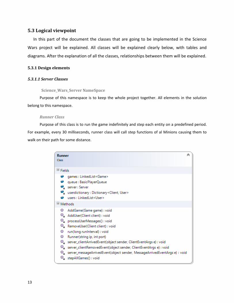
Runner Class
Purpose of this class is to run the game indefinitely and step each entity on a predefined period.
For example, every 30 milliseconds, runner class will call step functions of al Minions causing them to
walk on their path for some distance.
14
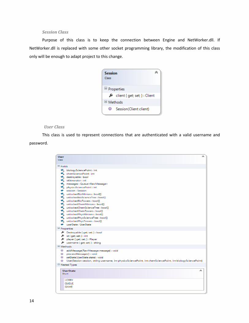
Session Class
Purpose of this class is to keep the connection between Engine and NetWorker.dll. If
NetWorker.dll is replaced with some other socket programming library, the modification of this class
only will be enough to adapt project to this change.
User Class
This class is used to represent connections that are authenticated with a valid username and
password.
15
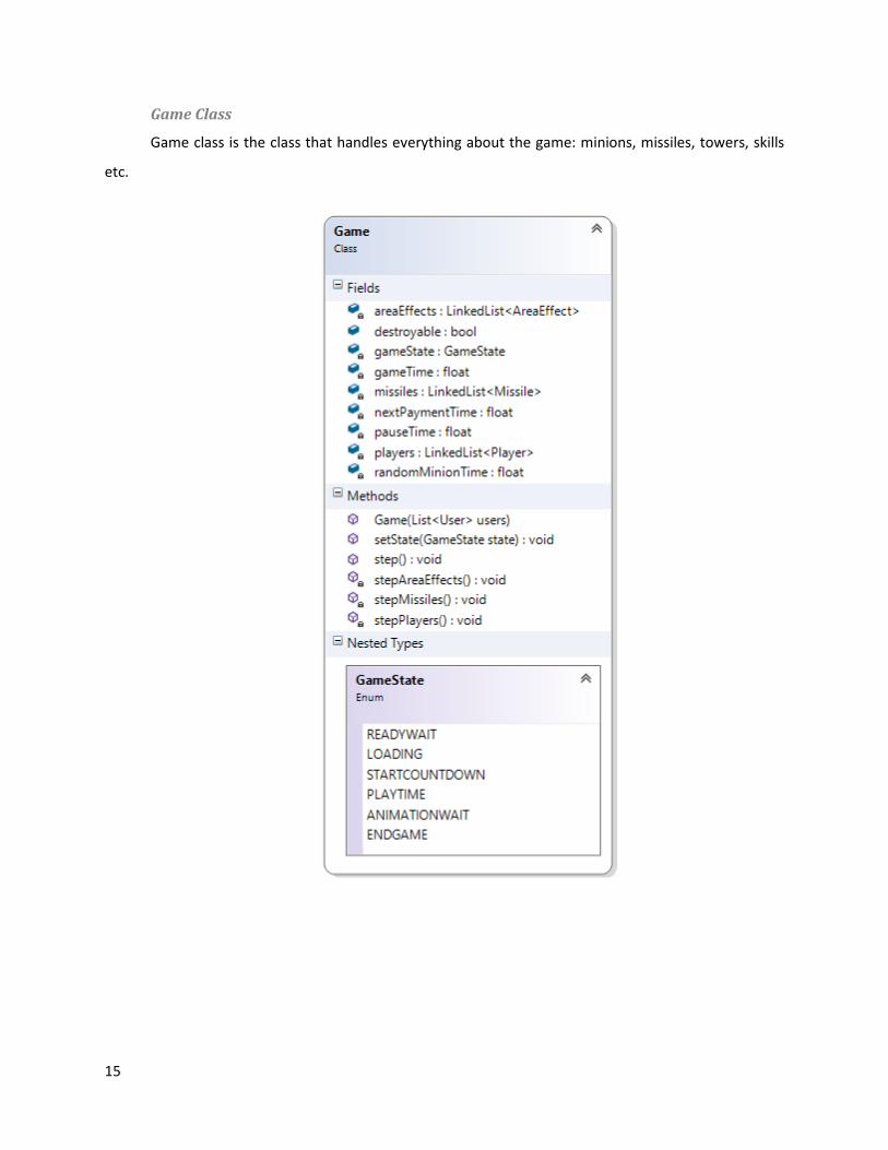
Game Class
Game class is the class that handles everything about the game: minions, missiles, towers, skills
etc.
16
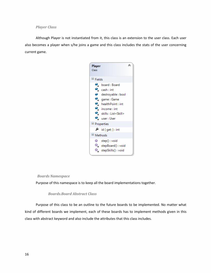
Player Class
Although Player is not instantiated from it, this class is an extension to the user class. Each user
also becomes a player when s/he joins a game and this class includes the stats of the user concerning
current game.
Boards Namespace
Purpose of this namespace is to keep all the board implementations together.
Boards.Board Abstract Class
Purpose of this class to be an outline to the future boards to be implemented. No matter what
kind of different boards we implement, each of these boards has to implement methods given in this
class with abstract keyword and also include the attributes that this class includes.

17
Towers Namespace
Purpose of this namespace is to keep all the tower implementations together.
Towers.Tower Abstract Class
Purpose of this class to be an outline to the future towers to be implemented. No matter what
kind of different towers we implement, each of these towers has to implement methods given in this
class with abstract keyword and also include the attributes that this class includes.

18
Towers.TowerNode Class
TowerNodes are basically nodes of a Tower tree. Each child of a node means that the parent
tower can be upgraded to its child tower.
Minions Namespace
Purpose of this namespace is to keep all the minion implementations together.
Minions.Minion Abstract Class
Purpose of this class to be an outline to the future minions to be implemented. No matter what
kind of different minions we implement, each of these minions has to implement methods given in this
class with abstract keyword and also include the attributes that this class includes.

19
Missiles Namespace
Purpose of this namespace is to keep all the missile implementations together
Missiles.Missile Abstract Class
Purpose of this class to be an outline to the future missiles to be implemented. No matter what
kind of different missiles we implement, each of these missiles has to implement methods given in this
class with abstract keyword and also include the attributes that this class includes.
AreaEffects Namespace
Purpose of this namespace is to keep all the area-effect implementations together.

20
AreaEffects.AreaEffect Abstract Class
Purpose of this class to be an outline to the future AreaEffects to be implemented. No matter
what kind of different AreaEffects we implement, each of these AreaEffects has to implement methods
given in this class with abstract keyword and also include the attributes that this class includes.
Skills Namespace
Purpose of this namespace is to keep all the skill implementations together.
Skills.Skill Abstract Class
Purpose of this class to be an outline to the future skills to be implemented. No matter what kind
of different skills we implement, each of these skills has to implement methods given in this class with
abstract keyword and also include the attributes that this class includes.
Queues Namespace
Purpose of this namespace is to keep all the queue implementations together.
21
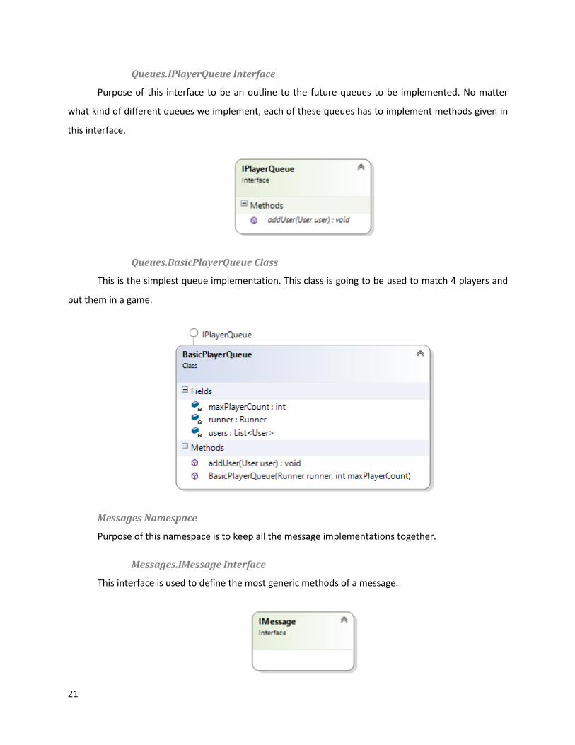
Queues.IPlayerQueue Interface
Purpose of this interface to be an outline to the future queues to be implemented. No matter
what kind of different queues we implement, each of these queues has to implement methods given in
this interface.
Queues.BasicPlayerQueue Class
This is the simplest queue implementation. This class is going to be used to match 4 players and
put them in a game.
Messages Namespace
Purpose of this namespace is to keep all the message implementations together.
Messages.IMessage Interface
This interface is used to define the most generic methods of a message.

22
Messages.IIncomingMessage Interface
Purpose of this interface to be an outline to the future incoming-messages to be implemented.
No matter what kind of different incoming-messages we implement, each of these incoming-messages
has to implement methods given in this interface.
Messages.IncomingMessageImp Abstract Class
Purpose of this class is to implement the basic operations that each incoming message needs to
implement. By using this class, we make sure that no duplicate codes included in the incoming message
implementations.
Messages.IOutgoingMessage Interface
Purpose of this interface to be an outline to the future outgoing-messages to be implemented.
No matter what kind of different outgoing-messages we implement, each of these outgoing-messages
has to implement methods given in this interface.

23
Messages.OutgoingMessageImp Abstract Class
Purpose of this class is to implement the basic operations that each outgoing message needs to
implement. By using this class, we make sure that no duplicate codes included in the outgoing message
implementations.
Paths Namespace
Purpose of this namespace is to keep all the path implementations together.
Paths.IPath Interface
Purpose of this interface to be an outline to the future paths to be implemented. No matter what
kind of different outgoing-messages we implement, each of these paths has to implement methods
given in this interface.
ResourceManager Namespace
Purpose of this namespace is to keep all the entities related to resource loading together.
ResourceManager.ResourceLoader Static Class
Purpose of this class is to load all file based resources from disks for all the classes that
implement IRequiresResource.

24
ResourceManager.IRequiresResource Interface
Purpose of this interface is to label a class that it has some resources to be loaded during the
startup period of the server.
ScienceTrees Namespace
Purpose of this namespace is to keep all the entities related to science trees together.
ScienceTrees.ScienceTree Abstract Class
Purpose of this class is to implement the basic operations that each science-tree needs to
implement. By using this class, we make sure that no duplicate codes included in the science-tree
implementations.
ScienceTrees.PhysicsTree Class
This class is one of the 3 ScienceTree implementations. It holds scienceNodes that includes tower
and minion unlock options.
25
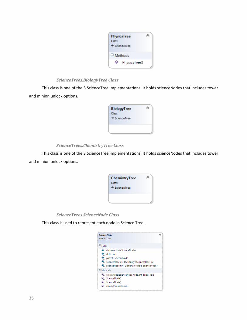
ScienceTrees.BiologyTree Class
This class is one of the 3 ScienceTree implementations. It holds scienceNodes that includes tower
and minion unlock options.
ScienceTrees.ChemistryTree Class
This class is one of the 3 ScienceTree implementations. It holds scienceNodes that includes tower
and minion unlock options.
ScienceTrees.ScienceNode Class
This class is used to represent each node in Science Tree.

26
GameUtilities Namespace
Purpose of this namespace is to keep all the entities related to science trees together.
GameUtilities.MinionPosition Class
This class is used to keep information about the position of a minion on the map.
GameUtilities.PathPosition Class
This class is used to specify a point on a path.
GameUtilities.TowerSlots Class
This class is used to keep the locations of the towers on a board.
GameUtilities.TypeIdGenerator Static Class
Purpose of this class is to make sure that entities are given proper ID’s on both server and client
so that both sides of the connection will know that they use the same language during the
communication over network.

27
Helpers Namespace
Purpose of this namespace is to keep all the helper classes together.
28
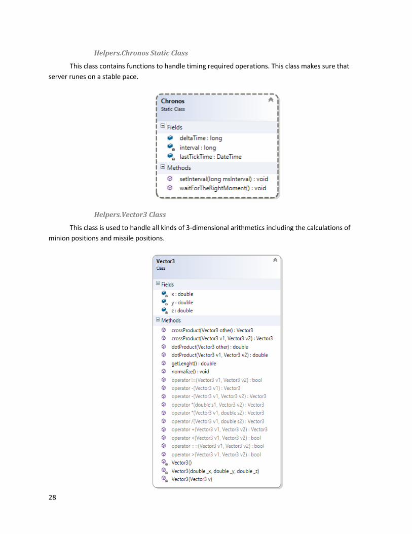
Helpers.Chronos Static Class
This class contains functions to handle timing required operations. This class makes sure that
server runes on a stable pace.
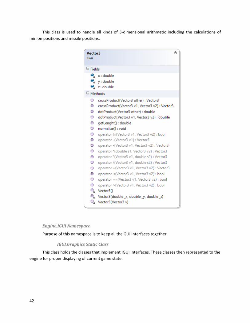
Helpers.Vector3 Class
This class is used to handle all kinds of 3-dimensional arithmetics including the calculations of
minion positions and missile positions.

29
5.3.1.2 Client Classes
Science_Wars_Client NameSpace
Purpose of this namespace is to keep the whole project together. All elements in the solution
belong to this namespace.
Engine.Runner Class
Purpose of this class is to run the game indefinitely and step each entity on a predefined period.
For example, every 30 milliseconds, runner class will call step functions of al Minions causing them to
walk on their path for some distance.
Engine.User Class
This class is used to represent connections that are authenticated with a valid username and
password. Client uses this class to provide chat and other social connections.
Engine.UserMe Static Class

30
This class includes every infomation related to the current logged-in user. This means
SciencePoints, unlocked towers, unlocked minons, friendlist and so on. Since each client can only login
to a single account at a given time, this class is static.
Engine.Player Class
This class is used to represent each player in the current game.
Engine.PlayerMe Static Class
This class is used to keep the data that is specific to the current player. Since each client can only
login to a single account at a given time, this class is static.

31
Engine.Game Static Class
Game class is the class that handles everything about the game: minions, missiles, towers, skills
etc. Since each client can only login to a single account at a given time, this class is static.

32
Engine.Boards Namespace
Purpose of this namespace is to keep all the board implementations together.
Boards.Board Abstract Class
Purpose of this class to be an outline to the future boards to be implemented. No matter what
kind of different boards we implement, each of these boards has to implement methods given in this
class with abstract keyword and also include the attributes that this class includes.
Engine.Towers Namespace
Purpose of this namespace is to keep all the tower implementations together.
Towers.Tower Abstract Class
Purpose of this class to be an outline to the future towers to be implemented. No matter what
kind of different towers we implement, each of these towers has to implement methods given in this
class with abstract keyword and also include the attributes that this class includes.

33
Towers.TowerNode Class
TowerNodes are basically nodes of a Tower tree. Each child of a node means that the parent
tower can be upgraded to its child tower.
Engine.Minions Namespace
Purpose of this namespace is to keep all the minion implementations together.
Minions.Minion Abstract Class
Purpose of this class to be an outline to the future minions to be implemented. No matter what
kind of different minions we implement, each of these minions has to implement methods given in this
class with abstract keyword and also include the attributes that this class includes.

34
Engine.Missiles Namespace
Purpose of this namespace is to keep all the missile implementations together
Missiles.Missile Abstract Class
Purpose of this class to be an outline to the future missiles to be implemented. No matter what
kind of different missiles we implement, each of these missiles has to implement methods given in this
class with abstract keyword and also include the attributes that this class includes.

35
Engine.AreaEffects Namespace
Purpose of this namespace is to keep all the area-effect implementations together.
AreaEffects.AreaEffect Abstract Class
Purpose of this class to be an outline to the future AreaEffects to be implemented. No matter
what kind of different AreaEffects we implement, each of these AreaEffects has to implement methods
given in this class with abstract keyword and also include the attributes that this class includes.
Engine.Skills Namespace
Purpose of this namespace is to keep all the skill implementations together.
Skills.Skill Abstract Class
Purpose of this class to be an outline to the future skills to be implemented. No matter what kind
of different skills we implement, each of these skills has to implement methods given in this class with
abstract keyword and also include the attributes that this class includes.
36
Engine.Messages Namespace
Purpose of this namespace is to keep all the message implementations together.
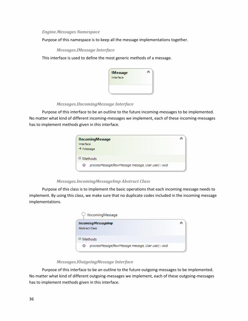
Messages.IMessage Interface
This interface is used to define the most generic methods of a message.
Messages.IIncomingMessage Interface
Purpose of this interface to be an outline to the future incoming-messages to be implemented.
No matter what kind of different incoming-messages we implement, each of these incoming-messages
has to implement methods given in this interface.
Messages.IncomingMessageImp Abstract Class
Purpose of this class is to implement the basic operations that each incoming message needs to
implement. By using this class, we make sure that no duplicate codes included in the incoming message
implementations.
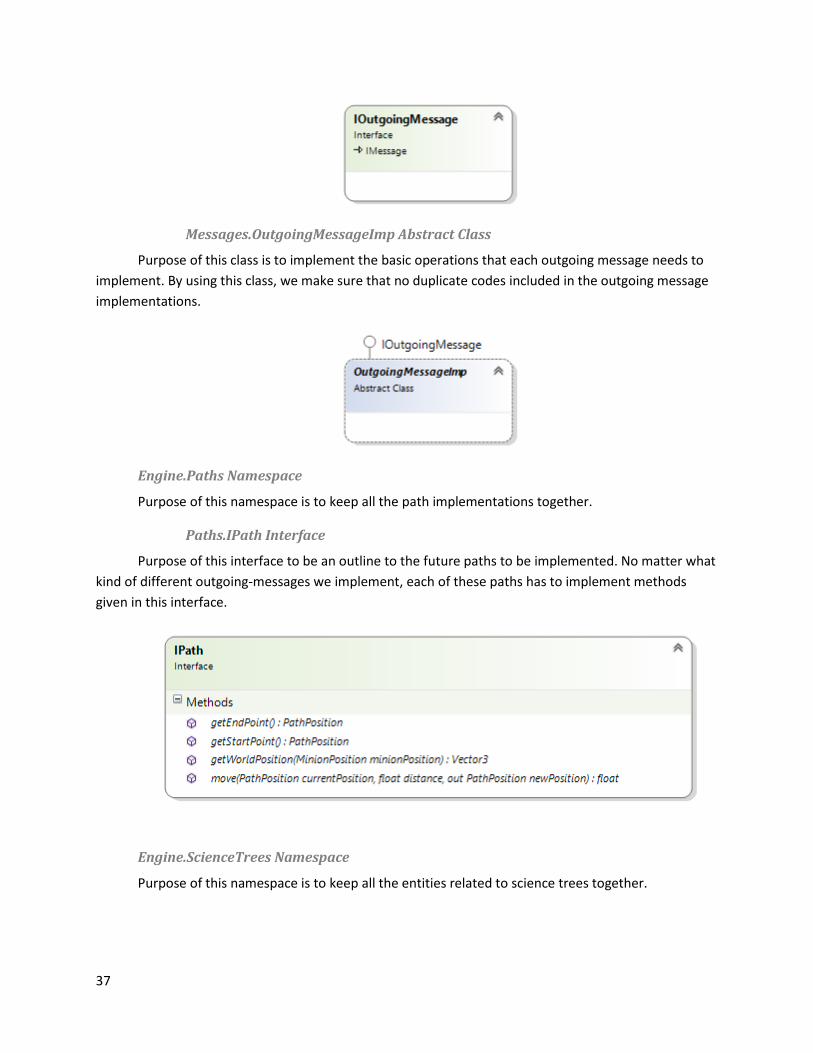
Messages.IOutgoingMessage Interface
Purpose of this interface to be an outline to the future outgoing-messages to be implemented.
No matter what kind of different outgoing-messages we implement, each of these outgoing-messages
has to implement methods given in this interface.
37
Messages.OutgoingMessageImp Abstract Class
Purpose of this class is to implement the basic operations that each outgoing message needs to
implement. By using this class, we make sure that no duplicate codes included in the outgoing message
implementations.
Engine.Paths Namespace
Purpose of this namespace is to keep all the path implementations together.
Paths.IPath Interface
Purpose of this interface to be an outline to the future paths to be implemented. No matter what
kind of different outgoing-messages we implement, each of these paths has to implement methods
given in this interface.
Engine.ScienceTrees Namespace
Purpose of this namespace is to keep all the entities related to science trees together.
38
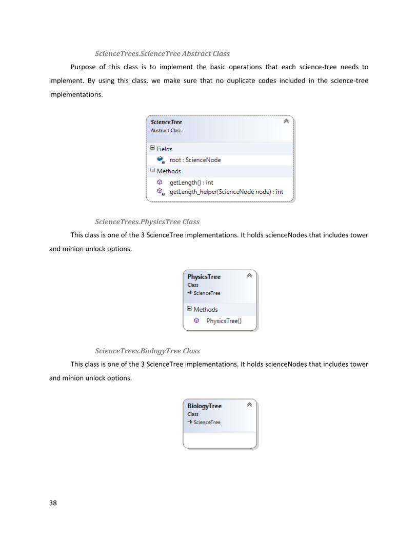
ScienceTrees.ScienceTree Abstract Class
Purpose of this class is to implement the basic operations that each science-tree needs to
implement. By using this class, we make sure that no duplicate codes included in the science-tree
implementations.
ScienceTrees.PhysicsTree Class
This class is one of the 3 ScienceTree implementations. It holds scienceNodes that includes tower
and minion unlock options.
ScienceTrees.BiologyTree Class
This class is one of the 3 ScienceTree implementations. It holds scienceNodes that includes tower
and minion unlock options.
39
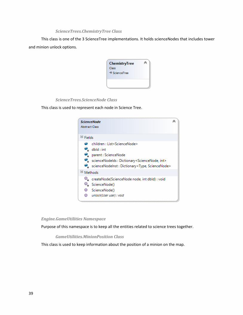
ScienceTrees.ChemistryTree Class
This class is one of the 3 ScienceTree implementations. It holds scienceNodes that includes tower
and minion unlock options.
ScienceTrees.ScienceNode Class
This class is used to represent each node in Science Tree.
Engine.GameUtilities Namespace
Purpose of this namespace is to keep all the entities related to science trees together.
GameUtilities.MinionPosition Class
This class is used to keep information about the position of a minion on the map.

40
GameUtilities.PathPosition Class
This class is used to specify a point on a path.
GameUtilities.TowerSlots Class
This class is used to keep the locations of the towers on a board.
GameUtilities.TypeIdGenerator
Purpose of this class is to make sure that entities are given proper ID’s on both server and client
so that both sides of the connection will know that they use the same language during the
communication over network.

41
Engine.Helpers Namespace
Purpose of this namespace is to keep all the helper classes together.
Helpers.Chronos Static Class
This class contains functions to handle timing required operations. This class makes sure that
server runes on a stable pace.
Helpers.Vector3 Class
42
This class is used to handle all kinds of 3-dimensional arithmetic including the calculations of
minion positions and missile positions.
Engine.IGUI Namespace
Purpose of this namespace is to keep all the GUI interfaces together.
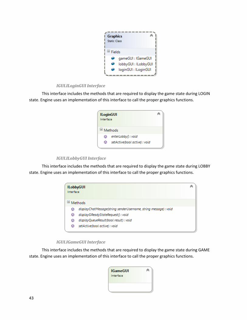
IGUI.Graphics Static Class
This class holds the classes that implement IGUI interfaces. These classes then represented to the
engine for proper displaying of current game state.
43
IGUI.ILoginGUI Interface
This interface includes the methods that are required to display the game state during LOGIN
state. Engine uses an implementation of this interface to call the proper graphics functions.
IGUI.ILobbyGUI Interface
This interface includes the methods that are required to display the game state during LOBBY
state. Engine uses an implementation of this interface to call the proper graphics functions.
IGUI.IGameGUI Interface
This interface includes the methods that are required to display the game state during GAME
state. Engine uses an implementation of this interface to call the proper graphics functions.
44
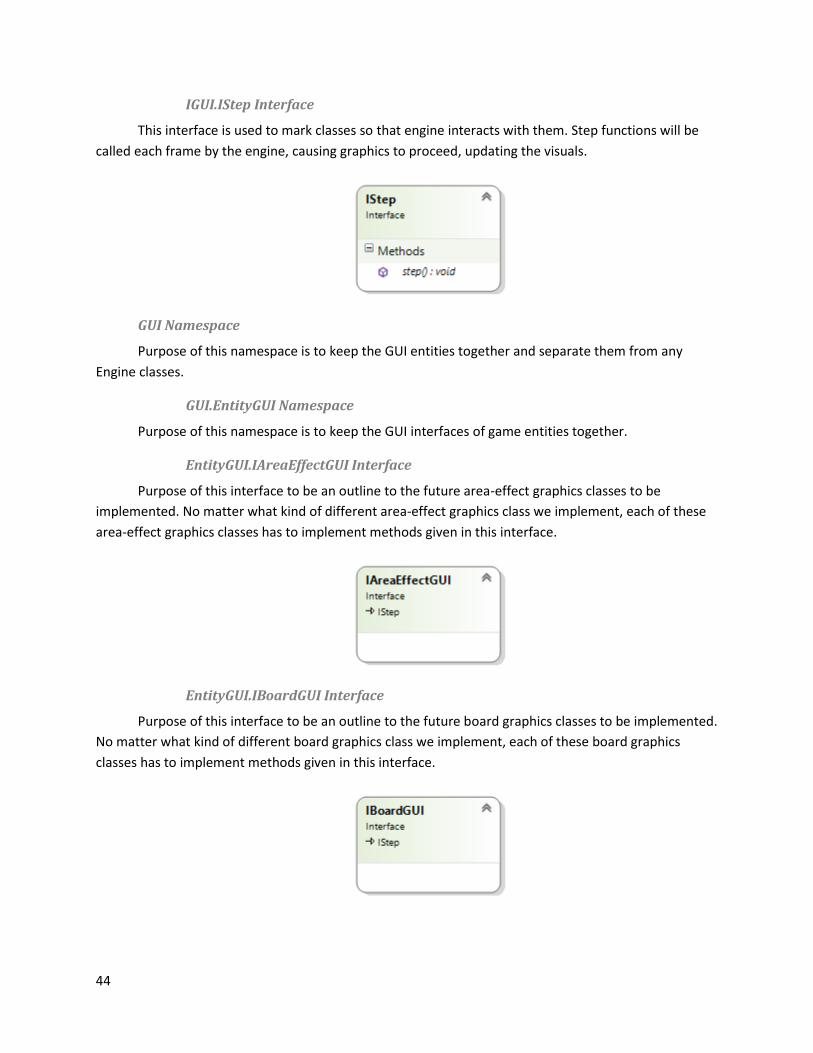
IGUI.IStep Interface
This interface is used to mark classes so that engine interacts with them. Step functions will be
called each frame by the engine, causing graphics to proceed, updating the visuals.
GUI Namespace
Purpose of this namespace is to keep the GUI entities together and separate them from any
Engine classes.
GUI.EntityGUI Namespace
Purpose of this namespace is to keep the GUI interfaces of game entities together.
EntityGUI.IAreaEffectGUI Interface
Purpose of this interface to be an outline to the future area-effect graphics classes to be
implemented. No matter what kind of different area-effect graphics class we implement, each of these
area-effect graphics classes has to implement methods given in this interface.
EntityGUI.IBoardGUI Interface
Purpose of this interface to be an outline to the future board graphics classes to be implemented.
No matter what kind of different board graphics class we implement, each of these board graphics
classes has to implement methods given in this interface.

45
EntityGUI.IMinionGUI Interface
Purpose of this interface to be an outline to the future minion graphics classes to be
implemented. No matter what kind of different minion graphics class we implement, each of these
minion graphics classes has to implement methods given in this interface.
EntityGUI.IMissileGUI Interface
Purpose of this interface to be an outline to the future missile graphics classes to be
implemented. No matter what kind of different missile graphics class we implement, each of these
missile graphics classes has to implement methods given in this interface.
EntityGUI.ISkillGUI Interface
Purpose of this interface to be an outline to the future skill graphics classes to be implemented.
No matter what kind of different skill graphics class we implement, each of these skill graphics classes
has to implement methods given in this interface.
EntityGUI.ITowerGUI Interface
Purpose of this interface to be an outline to the future tower graphics classes to be implemented.
No matter what kind of different tower graphics class we implement, each of these tower graphics
classes has to implement methods given in this interface.

46
GUIHandler Class
This class is used to make proper adjustments to bind the GUI and the Engine.
LoginGUI Class
This class is an implementation of ILoginGUI and it handles all the drawings that need to be done
during LOGIN phase.
LobbyGUI Class
This class is an implementation of ILobbyGUI and it handles all the drawings that need to be done
during LOBBY phase.

47
GameGUI Class
This class is an implementation of IGameGUI and it handles all the drawings that need to be done
during GAME phase.
5.4 Dependency viewpoint
In this section of document, the subsystem of the system and interconnections between those
subsystems will be defined in detail.
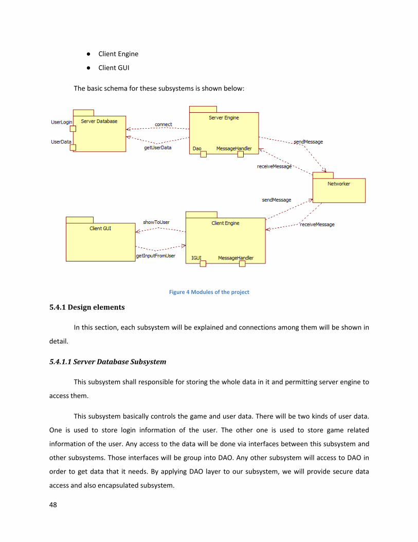
In this project, our system will have 5 main subsystems:
● Server Database
● Server Engine
● Networker
48
● Client Engine
● Client GUI
The basic schema for these subsystems is shown below:
Figure 4 Modules of the project
5.4.1 Design elements
In this section, each subsystem will be explained and connections among them will be shown in
detail.
5.4.1.1 Server Database Subsystem
This subsystem shall responsible for storing the whole data in it and permitting server engine to
access them.
This subsystem basically controls the game and user data. There will be two kinds of user data.
One is used to store login information of the user. The other one is used to store game related
information of the user. Any access to the data will be done via interfaces between this subsystem and
other subsystems. Those interfaces will be group into DAO. Any other subsystem will access to DAO in
order to get data that it needs. By applying DAO layer to our subsystem, we will provide secure data
access and also encapsulated subsystem.

49
5.4.1.2 Server Engine Subsystem
This subsystem mainly deals with gathering client requests, answering request results,
modifying data models and accessing to database.
In this subsystem, firstly, client requests are come as a message and then processed. Each
message has its own structure in this subsystem so that each message can reach any data model, can
modify them and can do any database access in order to supply its own needs.
As being main part of the server, this subsystem has a strong control over the server part. As a
result of this, every action that may change anything on the data should be handled by this component.
5.4.1.3 Networker Subsystem
In this subsystem, there will be two Networker DLLs, one is for the server and the other one is
for the client. Each Networker DLL is part of this subsystem and will work in a synchronized state with
other Networker DLL. In other words, it is guaranteed that every message sent by server has its
corresponding structure in the client and vice versa.
What this subsystem basically does is that it creates an interface between client and server so
that interaction between server and client can be done easily and fully correctly. As a result of this, this
subsystem will only interact with both Server Engine and Client Engine.
Networker Subsystem has its own classes and interfaces in it. Server Engine and Client Engine
use those interfaces in order to send and receive message. By means of this subsystem, in the future, if
we need to change anything in the network part, we will be able to connect this new component to our
whole system without any change.
5.4.1.4 Client Engine Subsystem
This subsystem is very similar subsystem with Server Engine. Since it is responsible for most of
the works in the Client, it will have very similar responsibility with the Server Engine.
This subsystem can be separated into 2 parts:
● Message Handler
● IGUI
50
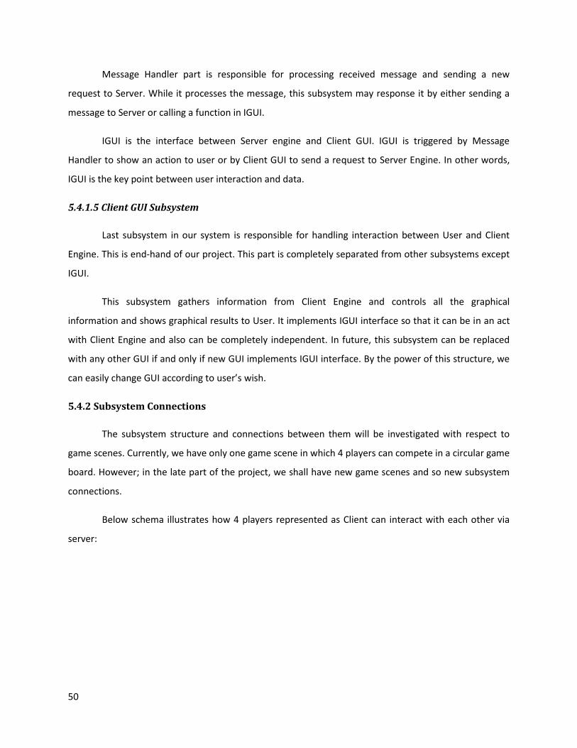
Message Handler part is responsible for processing received message and sending a new
request to Server. While it processes the message, this subsystem may response it by either sending a
message to Server or calling a function in IGUI.
IGUI is the interface between Server engine and Client GUI. IGUI is triggered by Message
Handler to show an action to user or by Client GUI to send a request to Server Engine. In other words,
IGUI is the key point between user interaction and data.
5.4.1.5 Client GUI Subsystem
Last subsystem in our system is responsible for handling interaction between User and Client
Engine. This is end-hand of our project. This part is completely separated from other subsystems except
IGUI.
This subsystem gathers information from Client Engine and controls all the graphical
information and shows graphical results to User. It implements IGUI interface so that it can be in an act
with Client Engine and also can be completely independent. In future, this subsystem can be replaced
with any other GUI if and only if new GUI implements IGUI interface. By the power of this structure, we
can easily change GUI according to user’s wish.
5.4.2 Subsystem Connections
The subsystem structure and connections between them will be investigated with respect to
game scenes. Currently, we have only one game scene in which 4 players can compete in a circular game
board. However; in the late part of the project, we shall have new game scenes and so new subsystem
connections.
Below schema illustrates how 4 players represented as Client can interact with each other via
server:
51
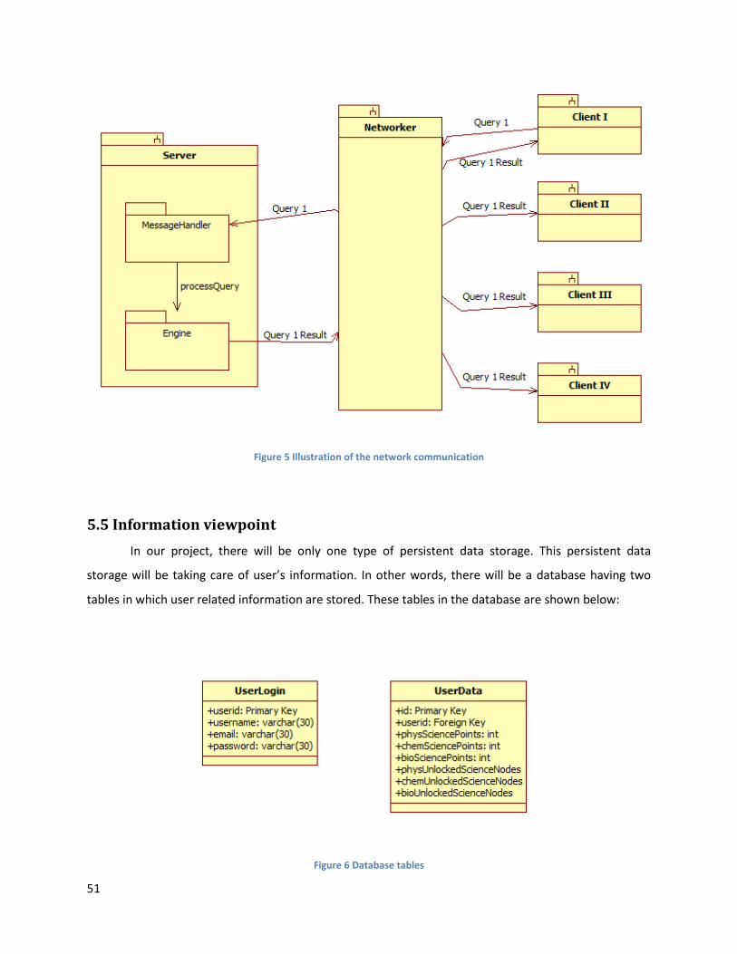
Figure 5 Illustration of the network communication
5.5 Information viewpoint
In our project, there will be only one type of persistent data storage. This persistent data
storage will be taking care of user’s information. In other words, there will be a database having two
tables in which user related information are stored. These tables in the database are shown below:
Figure 6 Database tables

52
From now on, the general structure of these tables, accessing methods and so on will be
explained.
General Structure
In our database, there will be two tables which are UserLogin and UserData. UserLogin will be
used to connect a user to server. After connecting a user to database, we will only use UserData table to
access user’s data.
The reason of having two databases is mainly priority difference of these two tables. Because
there is a password field of the UserLogin table, the accessing method to user’s password should be top-
secure. To make a connection top-secure, we will use SSL which needs more time than usual connection
methods. However, all users’ related information stored in the UserData table need fast access in order
to decrease database operation time so that game will not be delayed.
Accessing to Database
When the server application is opened, application connects to the database for a once by using
API called MySQL Connector/NET. After that, when a user is connected, we will check username
password pair by accessing UserLogin table and if the signing in is successful then we will read user
related datas from UserData table. As a result of this operation, we will be able to load and use user
data.
Changing the Database
When the server application is wanted to be closed, application writes to the database by using
same API used to access to database. The write operation will be done only when server is wanted to be
closed. However; in order to prevent from losing information in case of electricity or any external
problem, we will write the information to database in every 10 minutes interval.
Security of the Database
Because we are storing user passwords in the database, there should be encrypted connection
to the database so that passwords and other important data stored securely. In order to protect our
server and database, we will use SSL. However; due to high cost of SSL, we will only use it when user
tries to connect to server. In the other database accesses, we do not need to secure connection.

53
5.6 Interaction viewpoint
5.6.1 Design concerns
Science Wars is a multiplayer real-time strategy game. Science wars is a client-server type
application. The client and server will have their own network modules to talk interact with each other.
The client and server will use the “Networker.dll” which is coded by Bekir Öztürk. “Networker.dll” is a
network library with great capabilities which will help the team to achieve client - server side semantics
easily. The interaction between server and client will be explained in this section with the help of some
UML sequence diagrams.
5.6.2 Design elements
5.6.3 Login Interaction
Figure 7 Login Interaction
The above figure shows the login interaction between the Client and the Server side.
The client GUI module is responsible for catching the login attempt then telling the Client Engine that
the user wants to login, then the Client Engine is responsible interacting with the Server and making
semantically correct messaging protocols. The reason why Client GUI and Client Engine modules are

54
separated is that we want to reuse the Client Engine module when we put a new GUI interface to the
client like we will need to do for different platforms.
5.6.4 Enter Queue Interaction
Figure 8 EnterQueue Interaction
The above sequence diagram shows what kind of interaction happens between server and client
applications. The user (client) could want to enter game queue to play a game with other players. The
user can enter the queue with three different points of his/her own. There will be Physics, Biology and
Chemistry elo points for each user and the user will place the user to the game queue according to its
elo points. This sequence diagram above shows the process of entering game queue for a player in the
Lobby. Only the players in the lobby can enter to the game queue.
55
5.6.5 Game Found Interaction
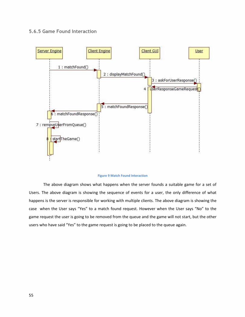
Figure 9 Match Found Interaction
The above diagram shows what happens when the server founds a suitable game for a set of
Users. The above diagram is showing the sequence of events for a user, the only difference of what
happens is the server is responsible for working with multiple clients. The above diagram is showing the
case when the User says “Yes” to a match found request. However when the User says “No” to the
game request the user is going to be removed from the queue and the game will not start, but the other
users who have said “Yes” to the game request is going to be placed to the queue again.
56
5.6.6 Build Tower Interaction
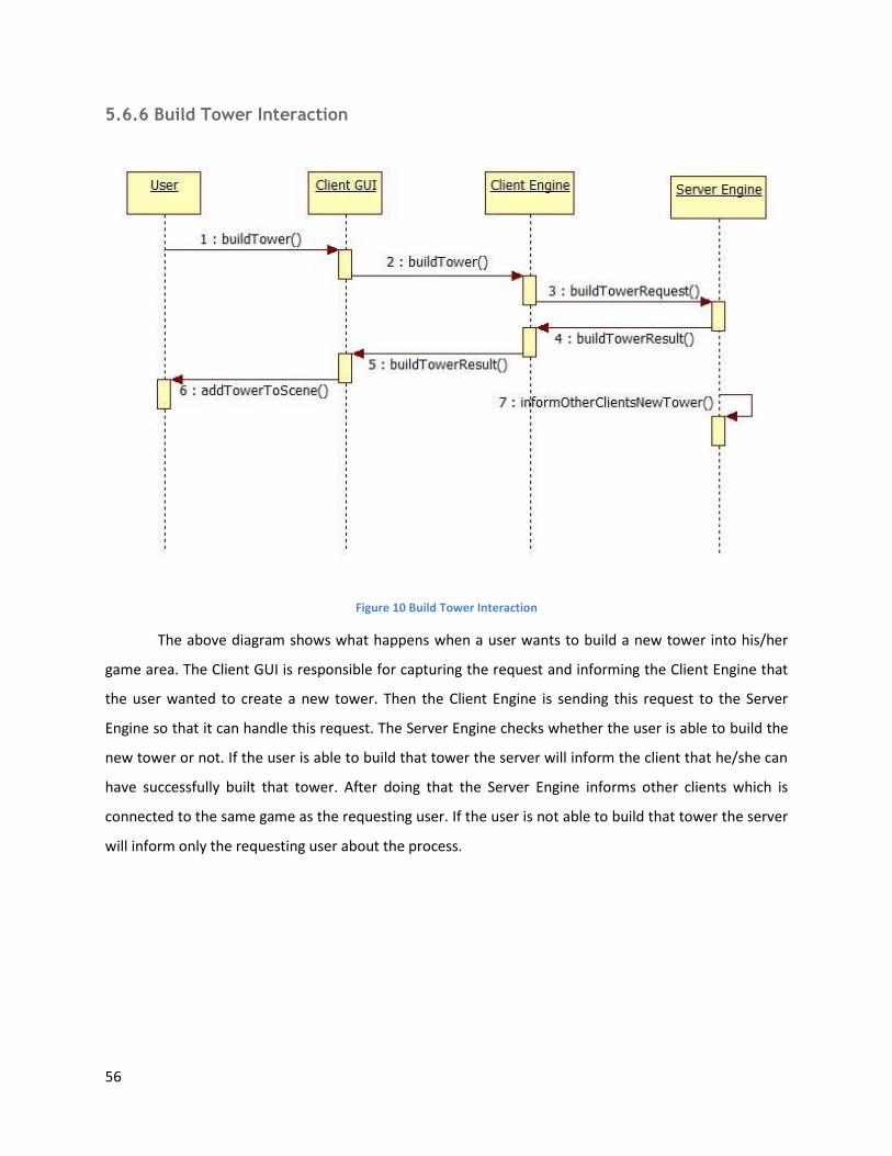
Figure 10 Build Tower Interaction
The above diagram shows what happens when a user wants to build a new tower into his/her
game area. The Client GUI is responsible for capturing the request and informing the Client Engine that
the user wanted to create a new tower. Then the Client Engine is sending this request to the Server
Engine so that it can handle this request. The Server Engine checks whether the user is able to build the
new tower or not. If the user is able to build that tower the server will inform the client that he/she can
have successfully built that tower. After doing that the Server Engine informs other clients which is
connected to the same game as the requesting user. If the user is not able to build that tower the server
will inform only the requesting user about the process.
57
5.6.7 Spawn Minion Interaction
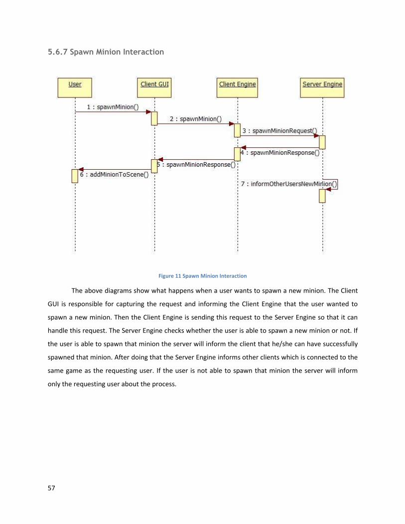
Figure 11 Spawn Minion Interaction
The above diagrams show what happens when a user wants to spawn a new minion. The Client
GUI is responsible for capturing the request and informing the Client Engine that the user wanted to
spawn a new minion. Then the Client Engine is sending this request to the Server Engine so that it can
handle this request. The Server Engine checks whether the user is able to spawn a new minion or not. If
the user is able to spawn that minion the server will inform the client that he/she can have successfully
spawned that minion. After doing that the Server Engine informs other clients which is connected to the
same game as the requesting user. If the user is not able to spawn that minion the server will inform
only the requesting user about the process.
58
5.6.8 Upgrade Tower Interaction
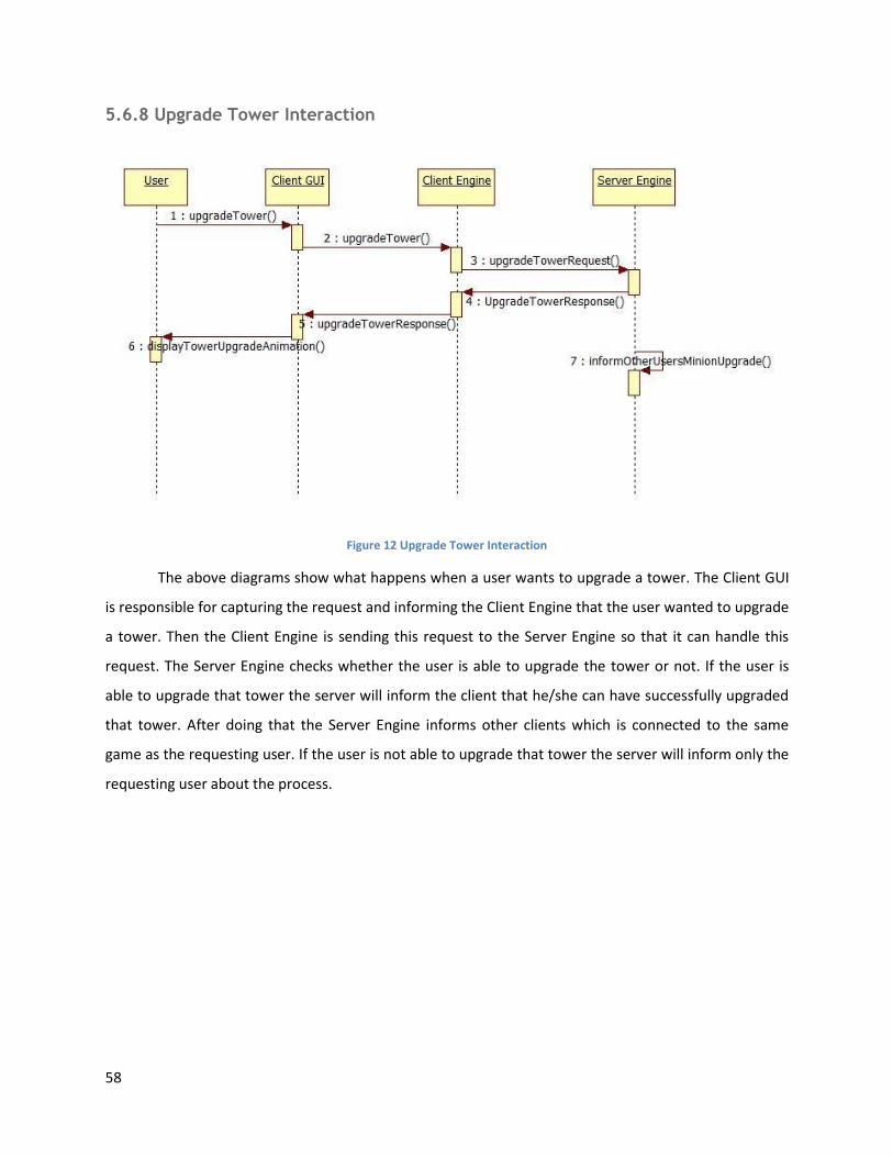
Figure 12 Upgrade Tower Interaction
The above diagrams show what happens when a user wants to upgrade a tower. The Client GUI
is responsible for capturing the request and informing the Client Engine that the user wanted to upgrade
a tower. Then the Client Engine is sending this request to the Server Engine so that it can handle this
request. The Server Engine checks whether the user is able to upgrade the tower or not. If the user is
able to upgrade that tower the server will inform the client that he/she can have successfully upgraded
that tower. After doing that the Server Engine informs other clients which is connected to the same
game as the requesting user. If the user is not able to upgrade that tower the server will inform only the
requesting user about the process.

59
5.6.9 Upgrade Minion Interaction
Figure 13 Upgrade Minion Interaction
The above diagrams show what happens when a user wants to upgrade a minion. The Client GUI
is responsible for capturing the request and informing the Client Engine that the user wanted to upgrade
a minion. Then the Client Engine is sending this request to the Server Engine so that it can handle this
request. The Server Engine checks whether the user is able to upgrade the minion or not. If the user is
able to upgrade that minion the server will inform the client that he/she can have successfully upgraded
that minion. After doing that the Server Engine informs other clients which is connected to the same
game as the requesting user. If the user is not able to upgrade that minion the server will inform only
the requesting user about the process.
60
5.6.10 Use Skill Interaction
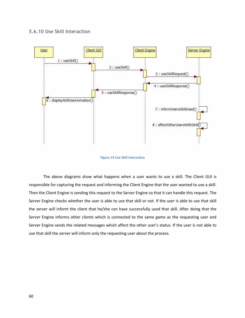
Figure 14 Use Skill Interaction
The above diagrams show what happens when a user wants to use a skill. The Client GUI is
responsible for capturing the request and informing the Client Engine that the user wanted to use a skill.
Then the Client Engine is sending this request to the Server Engine so that it can handle this request. The
Server Engine checks whether the user is able to use that skill or not. If the user is able to use that skill
the server will inform the client that he/she can have successfully used that skill. After doing that the
Server Engine informs other clients which is connected to the same game as the requesting user and
Server Engine sends the related messages which affect the other user’s status. If the user is not able to
use that skill the server will inform only the requesting user about the process.
61
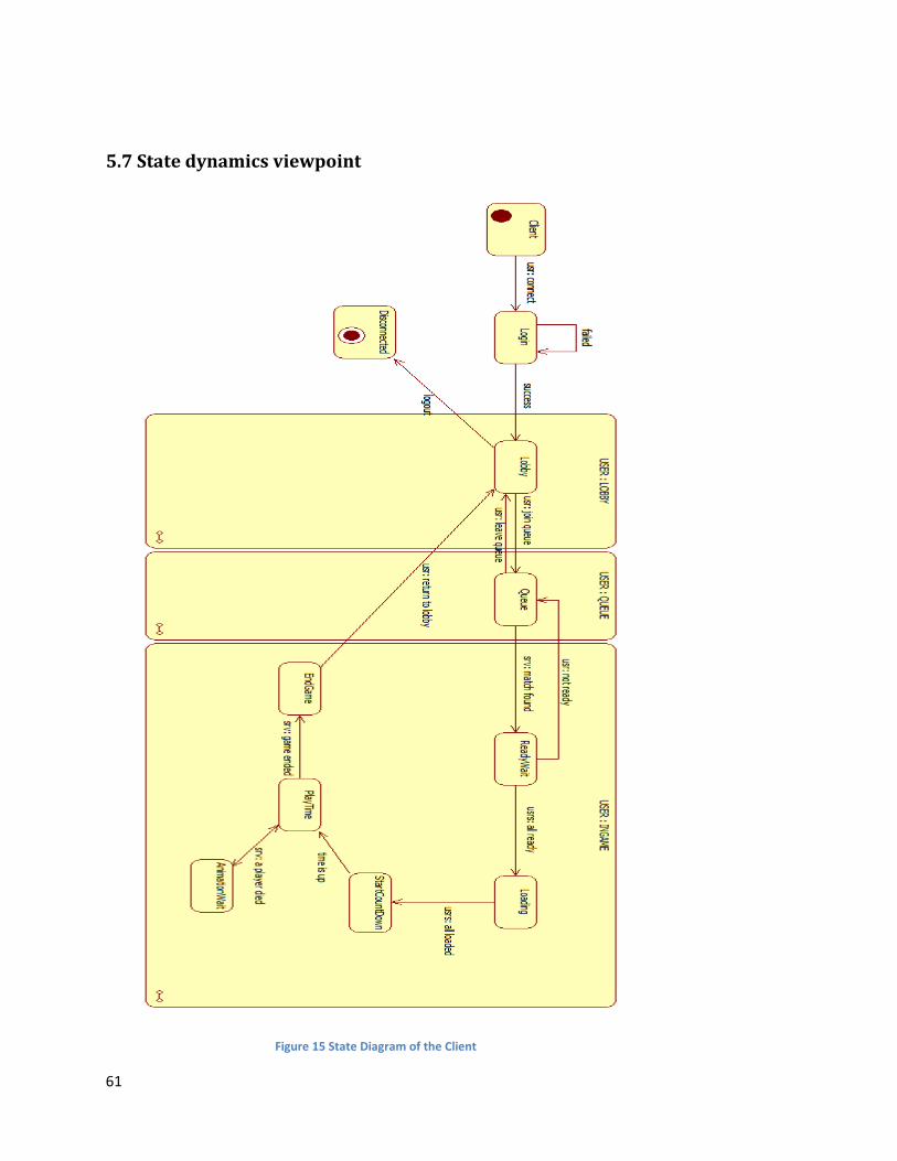
5.7 State dynamics viewpoint
Figure 15 State Diagram of the Client
62
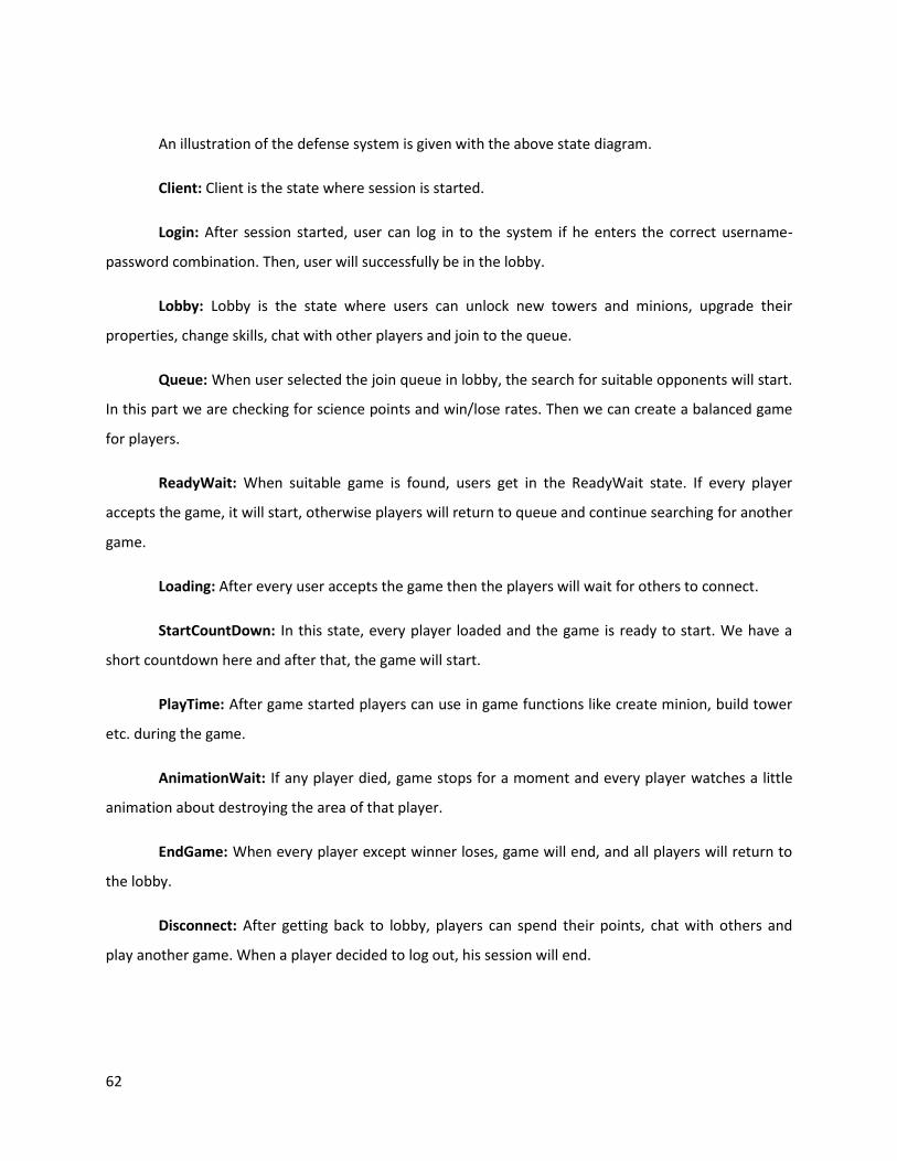
An illustration of the defense system is given with the above state diagram.
Client: Client is the state where session is started.
Login: After session started, user can log in to the system if he enters the correct username-
password combination. Then, user will successfully be in the lobby.
Lobby: Lobby is the state where users can unlock new towers and minions, upgrade their
properties, change skills, chat with other players and join to the queue.
Queue: When user selected the join queue in lobby, the search for suitable opponents will start.
In this part we are checking for science points and win/lose rates. Then we can create a balanced game
for players.
ReadyWait: When suitable game is found, users get in the ReadyWait state. If every player
accepts the game, it will start, otherwise players will return to queue and continue searching for another
game.
Loading: After every user accepts the game then the players will wait for others to connect.
StartCountDown: In this state, every player loaded and the game is ready to start. We have a
short countdown here and after that, the game will start.
PlayTime: After game started players can use in game functions like create minion, build tower
etc. during the game.
AnimationWait: If any player died, game stops for a moment and every player watches a little
animation about destroying the area of that player.
EndGame: When every player except winner loses, game will end, and all players will return to
the lobby.
Disconnect: After getting back to lobby, players can spend their points, chat with others and
play another game. When a player decided to log out, his session will end.
63
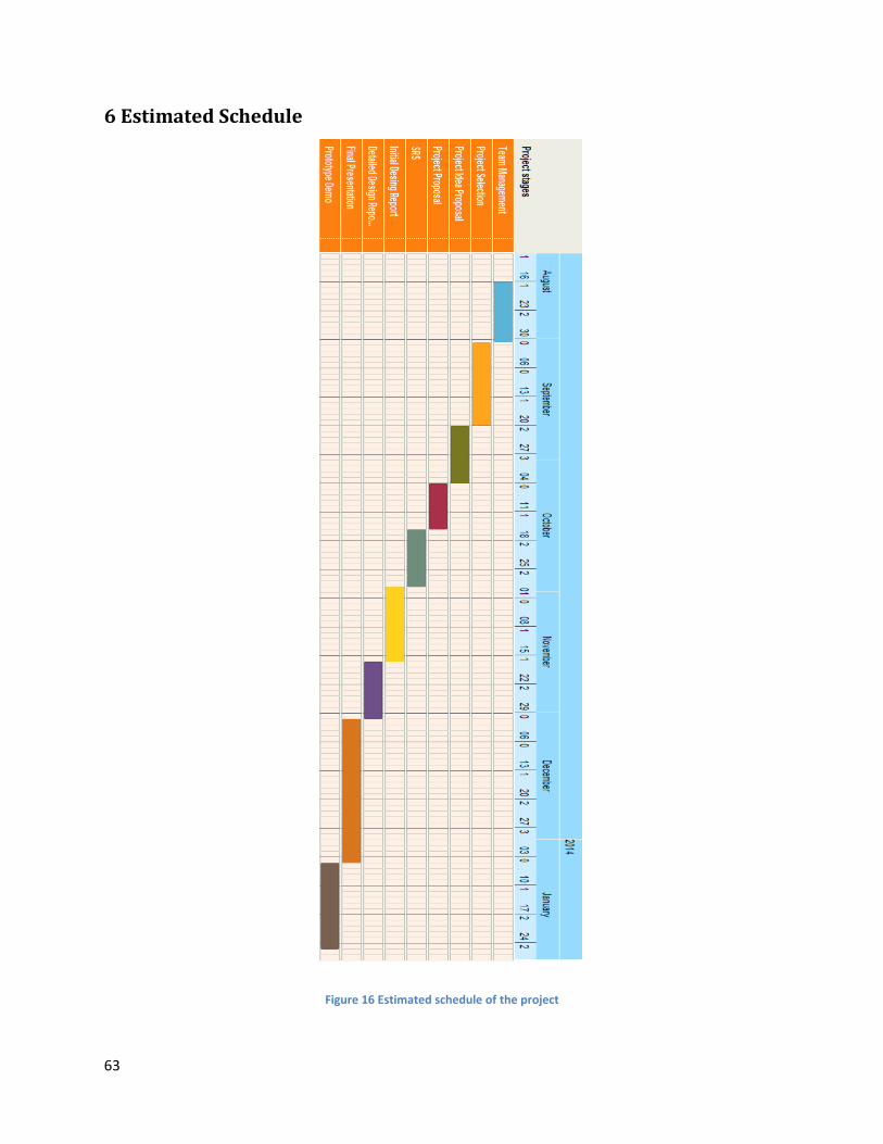
6 Estimated Schedule
Figure 16 Estimated schedule of the project

64
7 Conclusion
In this design document, we provide details about the software architecture and initial design of
the project Science Wars and also implementation details of the project with respect to viewpoints,
modules and data design. This document is intended to be used as a reference to the both stakeholders
defined before in this document and also to the team LeşKoding.

![Vector Quantization (LBG Algorithm) filelog 5 = 0,698 log 7 = 0,845 5 [TTG4J3] Koding dan Kompresi Pengantar Teori Informasi Dikembangkan oleh Elwood Shannon, electrical engineer di](https://static.fdocuments.us/doc/165x107/5d4e654a88c993d15f8b85ca/vector-quantization-lbg-algorithm-5-0698-log-7-0845-5-ttg4j3-koding-dan.jpg)