Software-based MIMO Channel Emulator - octoScope · Software-based MIMO Channel Emulator Fanny...
34
Software-based MIMO Channel Emulator Fanny Mlinarsky octoScope, Inc., Marlborough, MA, USA [email protected] Samuel MacMullan, Ph.D. ORB Analytics, Carlisle, MA, USA [email protected] 1
Transcript of Software-based MIMO Channel Emulator - octoScope · Software-based MIMO Channel Emulator Fanny...
Software-based
MIMO Channel Emulator Fanny Mlinarsky octoScope, Inc., Marlborough, MA, USA [email protected] Samuel MacMullan, Ph.D. ORB Analytics, Carlisle, MA, USA [email protected]
1

www.octoscope.com
Confidential
Outline
•What is channel emulation and why is it critical for MIMO systems?
• Channel modeling standards and technologies
• Channel model statistics
• Channel emulator implementation
2
www.octoscope.com
Confidential
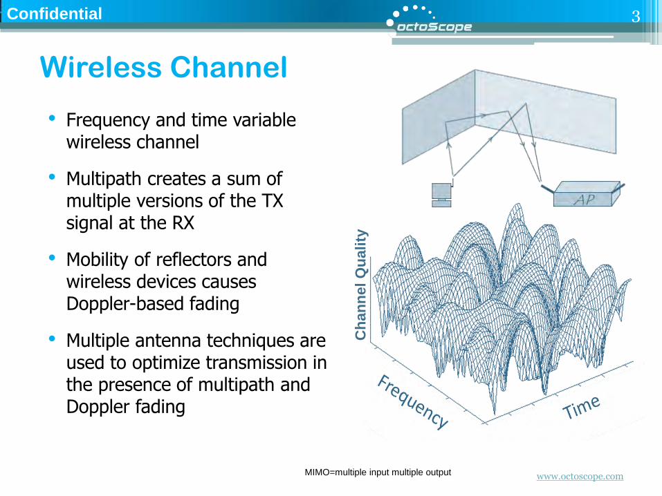
Wireless Channel
• Frequency and time variable wireless channel
• Multipath creates a sum of multiple versions of the TX signal at the RX
• Mobility of reflectors and wireless devices causes Doppler-based fading
• Multiple antenna techniques are used to optimize transmission in the presence of multipath and Doppler fading
3
Ch
an
nel
Qu
ality
MIMO=multiple input multiple output

www.octoscope.com
Confidential
Multipath and Flat Fading
• In a wireless channel the signal propagating from TX to RX experiences
Flat fading
Multipath/Doppler fading
Time
+10 dB 0 dB Multipath fading component
-15 dB flat fading component
Multipath reflections occur in clusters.
4

www.octoscope.com
Confidential
Multiple Antenna Techniques
• SISO (Single Input Single Output)
Traditional radio
• MISO (Multiple Input Single Output)
Transmit diversity (STBC, SFBC, CDD)
• SIMO (Single Input Multiple Output)
Receive diversity, MRC
• MIMO (Multiple Input Multiple Output)
SM to transmit multiple streams simultaneously; can be used in conjunction with CDD; works best in high SNR environments and channels de-correlated by multipath
TX and RX diversity, used independently or together; used to enhance throughput in the presence of adverse channel conditions
• Beamforming
SM = spatial multiplexing SFBC = space frequency block coding STBC = space time block coding CDD = cyclic delay diversity MRC = maximal ratio combining SM = Spatial Multiplexing SNR = signal to noise ratio
5
www.octoscope.com
Confidential
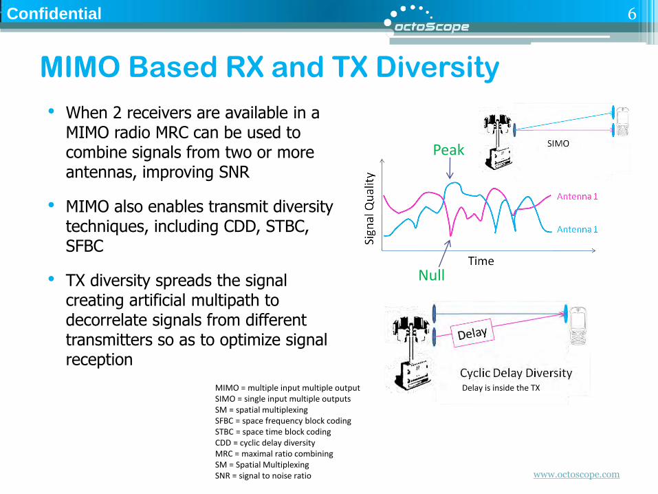
MIMO Based RX and TX Diversity
• When 2 receivers are available in a MIMO radio MRC can be used to combine signals from two or more antennas, improving SNR
• MIMO also enables transmit diversity techniques, including CDD, STBC, SFBC
• TX diversity spreads the signal creating artificial multipath to decorrelate signals from different transmitters so as to optimize signal reception
Peak
Null
MIMO = multiple input multiple output SIMO = single input multiple outputs SM = spatial multiplexing SFBC = space frequency block coding STBC = space time block coding CDD = cyclic delay diversity MRC = maximal ratio combining SM = Spatial Multiplexing SNR = signal to noise ratio
Delay is inside the TX
6
www.octoscope.com
Confidential
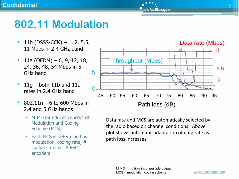
• 11b (DSSS-CCK) – 1, 2, 5.5, 11 Mbps in 2.4 GHz band
• 11a (OFDM) – 6, 9, 12, 18, 24, 36, 48, 54 Mbps in 5 GHz band
• 11g – both 11b and 11a rates in 2.4 GHz band
• 802.11n – 6 to 600 Mbps in 2.4 and 5 GHz bands
MIMO introduces concept of Modulation and Coding Scheme (MCS)
Each MCS is determined by modulation, coding rate, # spatial streams, # FEC encoders
802.11 Modulation
Data rate and MCS are automatically selected by the radio based on channel conditions. Above plot shows automatic adaptation of data rate as path loss increases.
Data rate (Mbps)
11
5.5
2
Throughput (Mbps)
5
0
Path loss (dB)
45 50 55 60 65 70 75 80 85 90 95
MIMO = multiple input multiple output
MCS = modulation coding scheme
1
7

www.octoscope.com
Confidential
20 MHz Channel 40 MHz Channel
1 stream 2 streams 3 streams 4 streams 1 stream 2 streams 3 streams 4 streams
Data Rate, in Mbps
802.11b
2.4 GHz
1, 2, 5.5,
11
802.11a
5 GHz
6, 9, 12,
18, 24, 36,
48, 54
802.11g
2.4 GHz
1, 2, 6, 9,
12, 18, 24,
36, 48, 54
802.11n
2.4 and
5 GHz
6.5, 13,
19.5, 26,
39, 52,
58.5, 65
13, 26, 39,
52, 78,
104, 117,
130
19.5, 39,
58.5, 78,
117, 156,
175.5, 195
26, 52, 78,
104, 156,
208, 234,
260
13.5, 27,
40.5, 54,
81, 108,
121.5, 135
27, 54, 81,
108, 162,
216, 243,
270
40.5, 81,
121.5, 162,
243, 324,
364.5, 405
54, 108,
162, 216,
324, 432,
486, 540
802.11n, SGI
enabled
2.4 and
5 GHz
7.2, 14.4,
21.7, 28.9,
43.3, 57.8,
65, 72.2
14.4, 28.9,
43.3, 57.8,
86.7,
115.6, 130,
144.4
21.7, 43.3,
65, 86.7,
130, 173.3,
195, 216.7
28.9, 57.8,
86.7,
115.6,
173.3,
231.1, 260,
288.9
15, 30, 45,
60, 90,
120, 135,
150
30, 60, 90,
120, 180,
240, 270,
300
45, 90,
135, 180,
270, 360,
405, 450
60, 120,
180, 240,
360, 480,
540, 600
IEEE 802.11a,b,g,n Data Rates
8
www.octoscope.com
Confidential
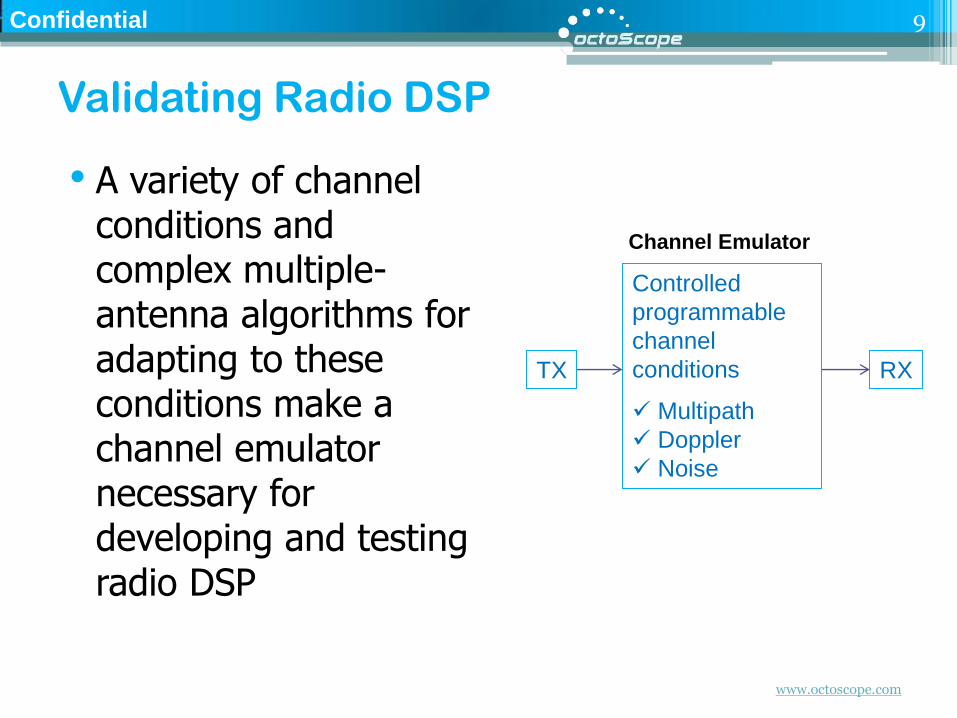
Validating Radio DSP
• A variety of channel conditions and complex multiple-antenna algorithms for adapting to these conditions make a channel emulator necessary for developing and testing radio DSP
9
TX RX
Controlled
programmable
channel
conditions
Multipath
Doppler
Noise
Channel Emulator
www.octoscope.com
Confidential
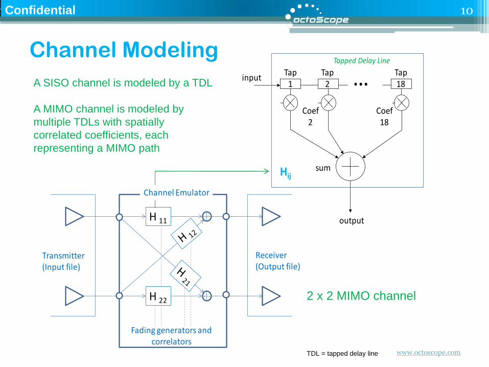
Channel Modeling
10
…Tap1
Tap2
Tap18
Tapped Delay Line
input
output
Coef2
Coef18
sumHij
H 11
Transmitter(Input file)
Receiver(Output file)
Channel Emulator
Fading generators and correlators
H 22
A SISO channel is modeled by a TDL
A MIMO channel is modeled by
multiple TDLs with spatially
correlated coefficients, each
representing a MIMO path
TDL = tapped delay line
2 x 2 MIMO channel
www.octoscope.com
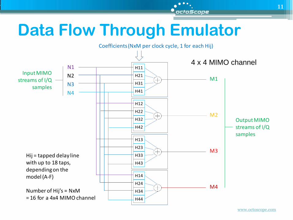
Data Flow Through Emulator
11
N1
N2
N3
N4
M1
M2
M3
M4
H14
H24
H34
H44
H13
H23
H33
H43
H12
H22
H32
H42
H11
H21
H31
H41
Input MIMO streams of I/Q
samples
Output MIMO streams of I/Q samples
Coefficients (NxM per clock cycle, 1 for each Hij)
Hij = tapped delay line with up to 18 taps, depending on the model (A-F)
Number of Hij’s = NxM= 16 for a 4x4 MIMO channel
4 x 4 MIMO channel
www.octoscope.com
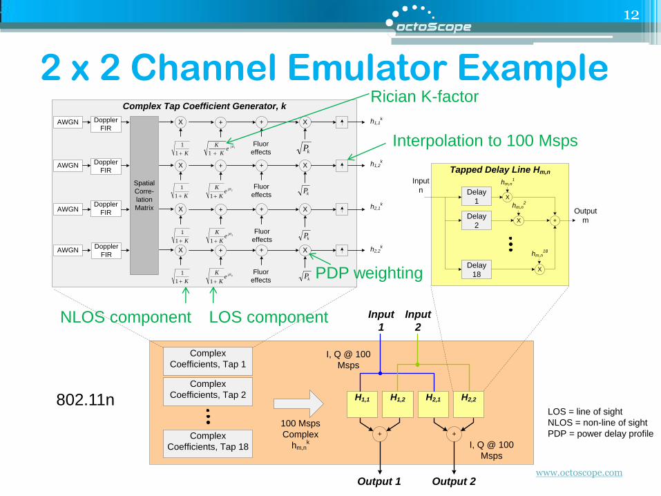
Tapped Delay Line Hm,n
Complex Tap Coefficient Generator, k
Spatial
Corre-
lation
Matrix
AWGN Doppler
FIR
kP
X
K1
1
X + h1,1k
AWGNDoppler
FIR
kP
XX + h1,2k
AWGNDoppler
FIR
kP
X
K1
1
X + h2,1k
AWGNDoppler
FIR
kP
X
K1
1
X + h2,2k
K1
1
Complex
Coefficients, Tap 18
X
+
Delay
1
Delay
2
Delay
18
X
X
Input
n
Output
m
H1,1
hm,n1
hm,n2
hm,n18
H1,2 H2,1 H2,2
+ +
100 Msps
Complex
hm,nk
Input
1
Input
2
Output 1 Output 2
I, Q @ 100
Msps
I, Q @ 100
Msps
Complex
Coefficients, Tap 2
Complex
Coefficients, Tap 1
2
1
je
K
K
3
1
je
K
K
4
1
je
K
K
1
1
je
K
K
+
+
+
+
Fluor
effects
Fluor
effects
Fluor
effects
Fluor
effects
2 x 2 Channel Emulator Example
12
Rician K-factor
NLOS component LOS component
Interpolation to 100 Msps
802.11n
PDP weighting
LOS = line of sight
NLOS = non-line of sight
PDP = power delay profile

www.octoscope.com
Confidential
Outline
•What is channel emulation and why is it critical for MIMO systems?
• Channel modeling standards and technologies
• Channel model statistics
• Channel emulator implementation
13
www.octoscope.com
Confidential
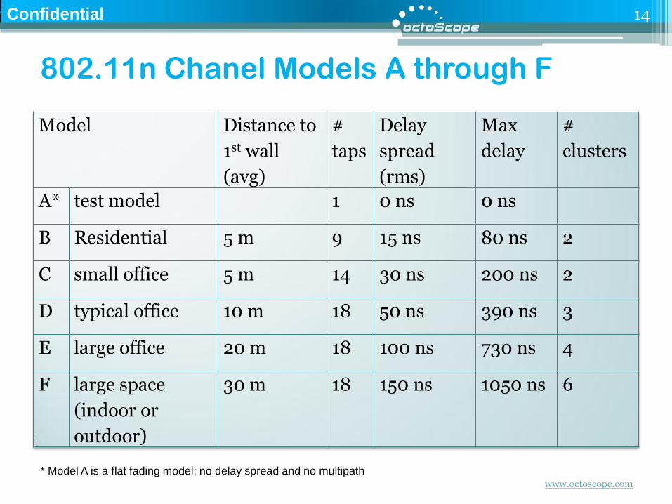
802.11n Chanel Models A through F
14
Model Distance to
1st wall
(avg)
#
taps
Delay
spread
(rms)
Max
delay
#
clusters
A* test model 1 0 ns 0 ns
B Residential 5 m 9 15 ns 80 ns 2
C small office 5 m 14 30 ns 200 ns 2
D typical office 10 m 18 50 ns 390 ns 3
E large office 20 m 18 100 ns 730 ns 4
F large space
(indoor or
outdoor)
30 m 18 150 ns 1050 ns 6
* Model A is a flat fading model; no delay spread and no multipath
www.octoscope.com
Confidential
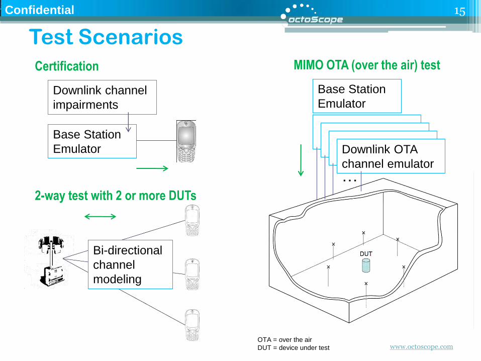
Test Scenarios
15
Base Station
Emulator
Certification
Downlink channel
impairments
2-way test with 2 or more DUTs
Bi-directional
channel
modeling
Downlink OTA
channel emulator
MIMO OTA (over the air) test
Base Station
Emulator
…
OTA = over the air
DUT = device under test
www.octoscope.com
Confidential
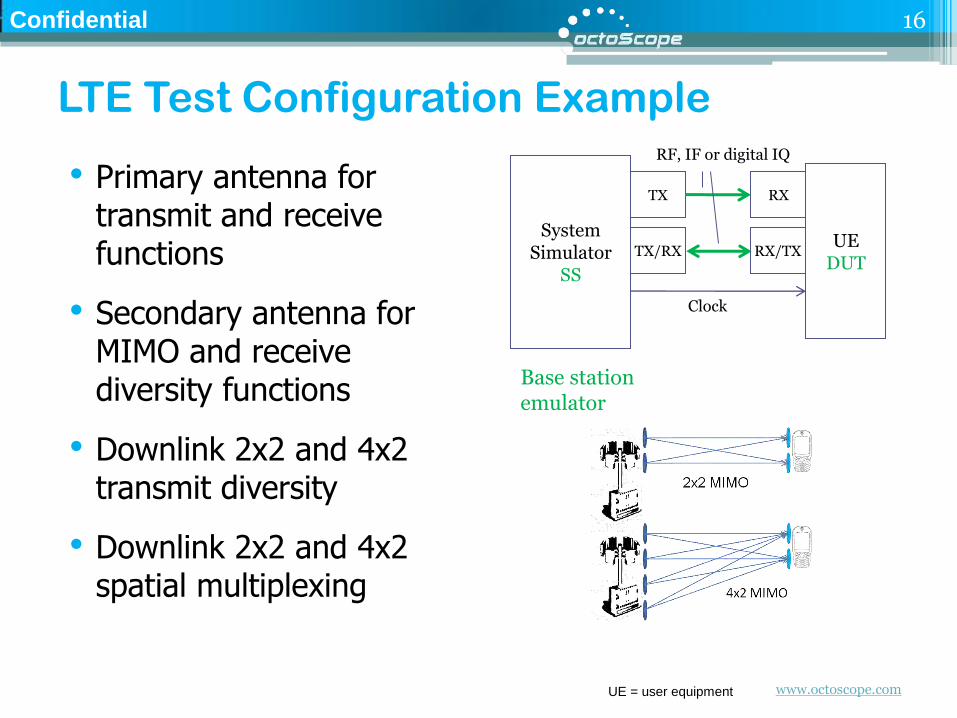
LTE Test Configuration Example
• Primary antenna for transmit and receive functions
• Secondary antenna for MIMO and receive diversity functions
• Downlink 2x2 and 4x2 transmit diversity
• Downlink 2x2 and 4x2 spatial multiplexing
16
UE DUT
System Simulator
SS
TX
TX/RX RX/TX
RX
Clock
RF, IF or digital IQ
Base station emulator
UE = user equipment
www.octoscope.com
Confidential
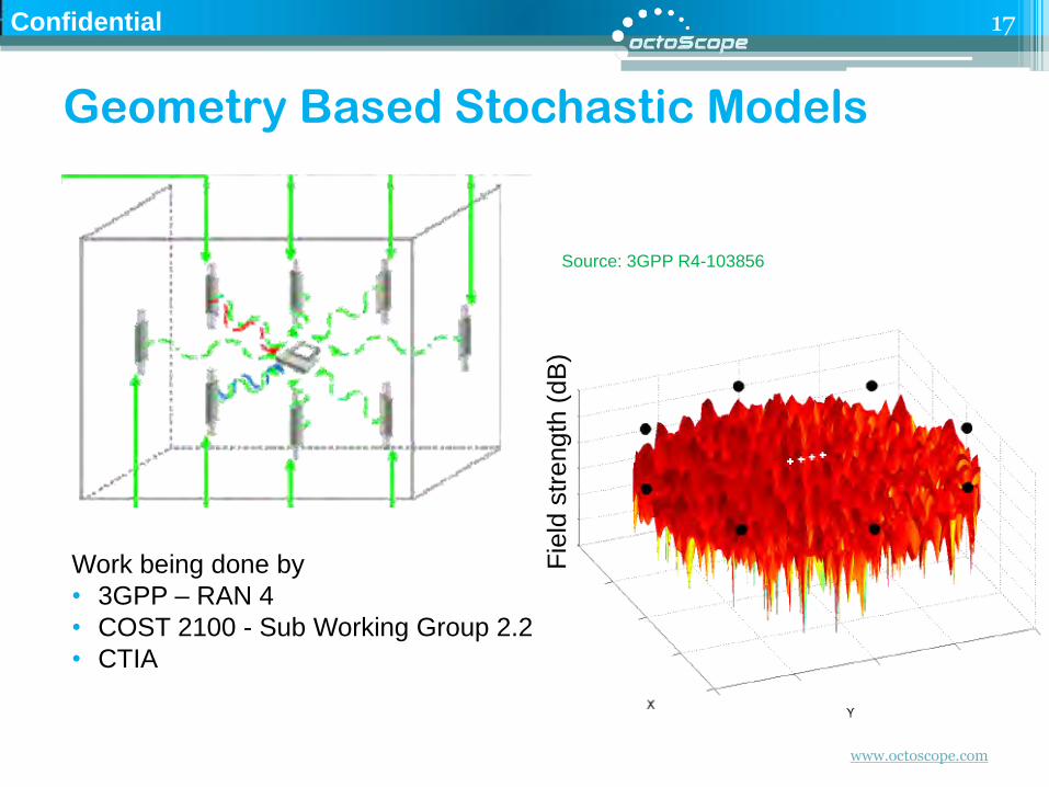
Geometry Based Stochastic Models
17
Fie
ld s
trength
(dB
) Work being done by
• 3GPP – RAN 4
• COST 2100 - Sub Working Group 2.2
• CTIA
Source: 3GPP R4-103856
www.octoscope.com
Confidential
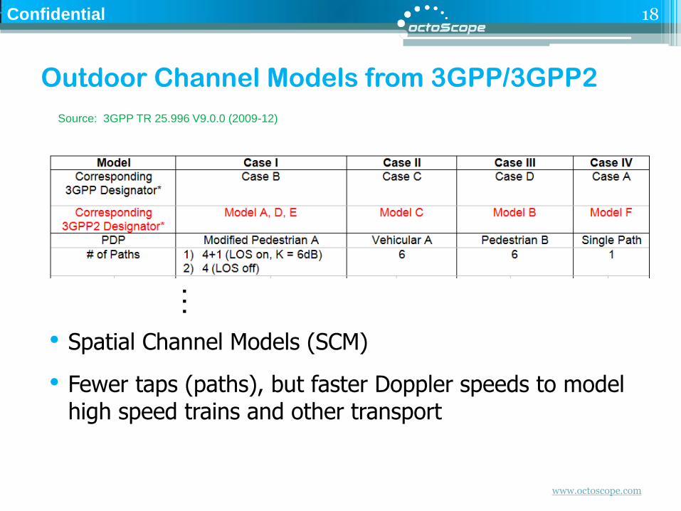
Outdoor Channel Models from 3GPP/3GPP2
• Spatial Channel Models (SCM)
• Fewer taps (paths), but faster Doppler speeds to model high speed trains and other transport
18
Source: 3GPP TR 25.996 V9.0.0 (2009-12)
…
www.octoscope.com
Confidential
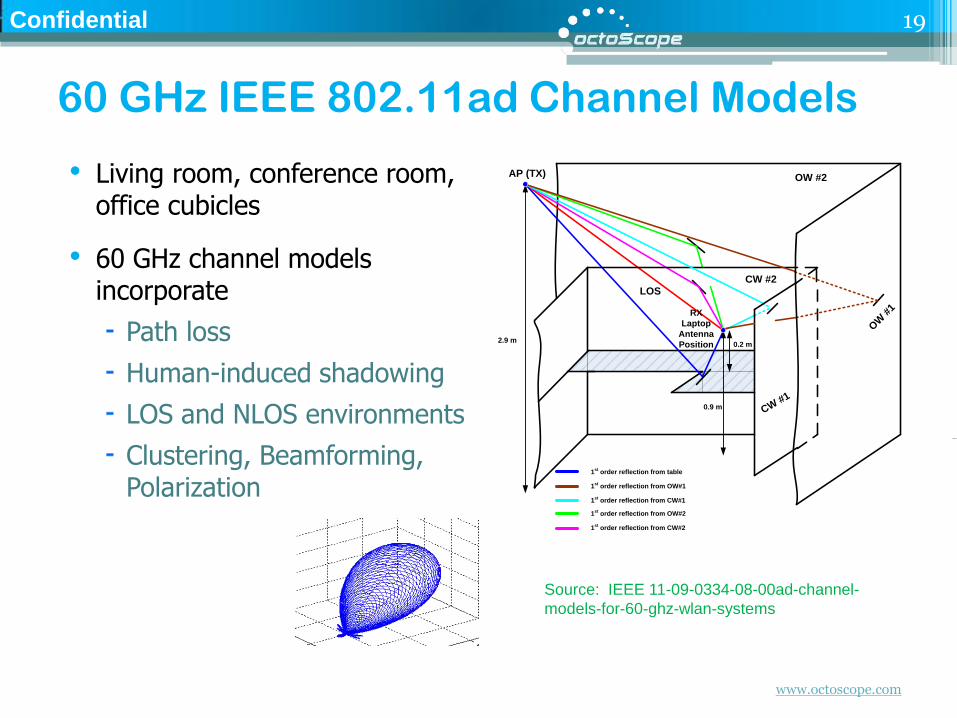
60 GHz IEEE 802.11ad Channel Models
• Living room, conference room, office cubicles
• 60 GHz channel models incorporate
Path loss
Human-induced shadowing
LOS and NLOS environments
Clustering, Beamforming, Polarization
19
0.9 m
AP (TX)
RX
Laptop
Antenna
Position
LOS
2.9 m0.2 m
1st
order reflection from table
1st
order reflection from OW#1
1st
order reflection from CW#1
1st
order reflection from OW#2
1st
order reflection from CW#2
OW #2
CW #2
CW #1
OW
#1
Source: IEEE 11-09-0334-08-00ad-channel-
models-for-60-ghz-wlan-systems
www.octoscope.com
Confidential
Outline
•What is channel emulation and why is it critical for MIMO systems?
• Channel modeling standards and technologies
• Channel model statistics
• Channel emulator implementation
20
www.octoscope.com
Confidential
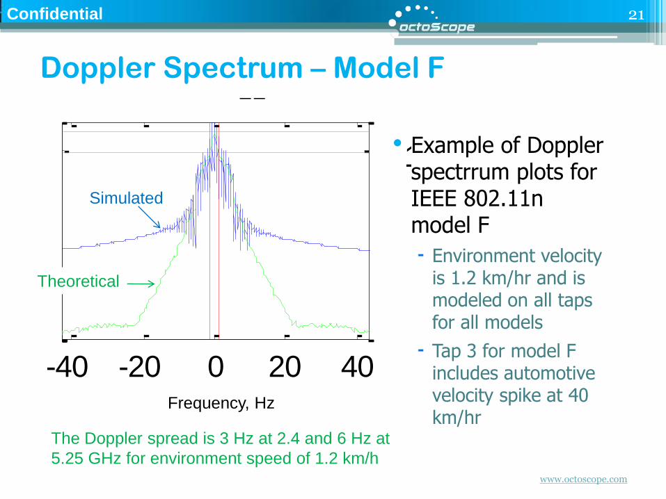
Doppler Spectrum – Model F
• Example of Doppler spectrrum plots for IEEE 802.11n model F
Environment velocity is 1.2 km/hr and is modeled on all taps for all models
Tap 3 for model F includes automotive velocity spike at 40 km/hr
21
-40 -20 0 20 40
100
Tap h111
-40 -20 0 20 40
100
Tap h112
-40 -20 0 20 40
100
Tap h113
-40 -20 0 20 40
100
Tap h114
-40 -20 0 20 40
100
Tap h115
-40 -20 0 20 40
100
Tap h116
-40 -20 0 20 40
100
Tap h121
-40 -20 0 20 40
100
Tap h122
-40 -20 0 20 40
100
Tap h123
-40 -20 0 20 40
100
Tap h124
-40 -20 0 20 40
100
Tap h125
-40 -20 0 20 40
100
Tap h126
-40 -20 0 20 40
100
Tap h211
-40 -20 0 20 40
100
Tap h212
-40 -20 0 20 40
100
Tap h213
-40 -20 0 20 40
100
Tap h214
-40 -20 0 20 40
100
Tap h215
-40 -20 0 20 40
100
Tap h216
-40 -20 0 20 40
100
Tap h221
-40 -20 0 20 40
100
Tap h222
-40 -20 0 20 40
100
Tap h223
-40 -20 0 20 40
100
Tap h224
-40 -20 0 20 40
100
Tap h225
-40 -20 0 20 40
100
Tap h226
Theoretical
Simulated
The Doppler spread is 3 Hz at 2.4 and 6 Hz at
5.25 GHz for environment speed of 1.2 km/h
Frequency, Hz
www.octoscope.com
Confidential
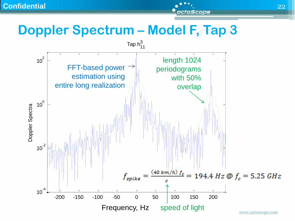
Doppler Spectrum – Model F, Tap 3
22
-200 -150 -100 -50 0 50 100 150 20010
-4
10-2
100
102
Frequency
Dopple
r S
pectr
a
Tap h113
FFT-based power
estimation using
entire long realization
length 1024
periodograms
with 50%
overlap
speed of light Frequency, Hz
www.octoscope.com
Confidential
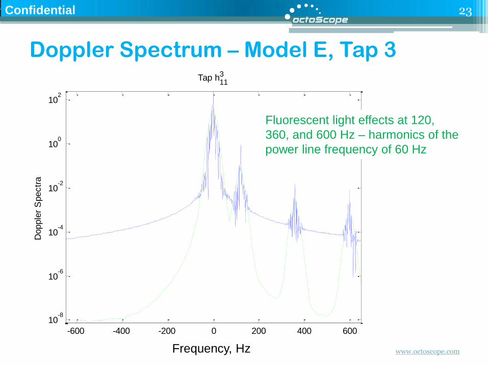
Doppler Spectrum – Model E, Tap 3
23
-600 -400 -200 0 200 400 600
10-8
10-6
10-4
10-2
100
102
Frequency
Dopple
r S
pectr
a
Tap h113
Fluorescent light effects at 120,
360, and 600 Hz – harmonics of the
power line frequency of 60 Hz
Frequency, Hz
www.octoscope.com
Confidential
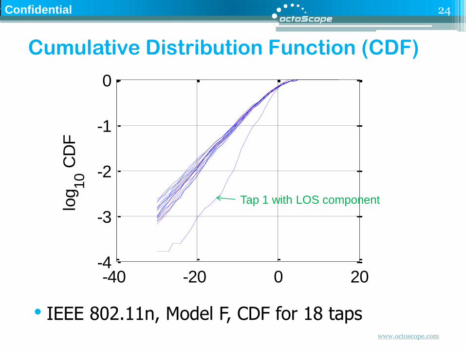
Cumulative Distribution Function (CDF)
• IEEE 802.11n, Model F, CDF for 18 taps
24
-40 -20 0 20-4
-3
-2
-1
0Tx#1 - Rx#1
log
10 C
DF
-40 -20 0 20-4
-3
-2
-1
0Tx#1 - Rx#2
-40 -20 0 20-4
-3
-2
-1
0Tx#2 - Rx#1
log
10 C
DF
20 log10
(h) [dB]
-40 -20 0 20-6
-4
-2
0Tx#2 - Rx#2
20 log10
(h) [dB]
Tap 1 with LOS component
www.octoscope.com
Confidential
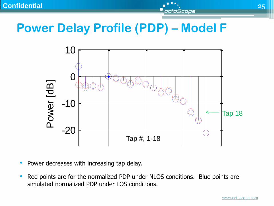
Power Delay Profile (PDP) – Model F
• Power decreases with increasing tap delay.
• Red points are for the normalized PDP under NLOS conditions. Blue points are simulated normalized PDP under LOS conditions.
25
5 10 15 20-30
-20
-10
0
10Tx#1 - Rx#1
Pow
er
[dB
]
5 10 15 20-30
-20
-10
0
10Tx#1 - Rx#2
5 10 15 20-30
-20
-10
0
10Tx#2 - Rx#1
Pow
er
[dB
]
Tap index
5 10 15 20-30
-20
-10
0
10Tx#2 - Rx#2
Tap index
Tap 18
Tap #, 1-18
www.octoscope.com
Confidential
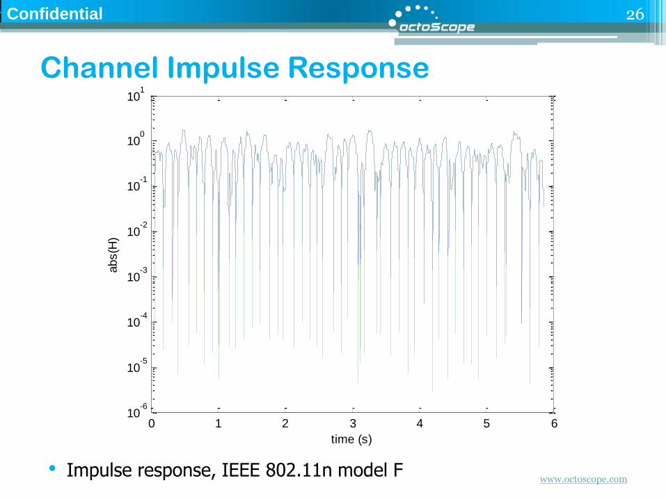
Channel Impulse Response
• Impulse response, IEEE 802.11n model F
26
0 1 2 3 4 5 610
-6
10-5
10-4
10-3
10-2
10-1
100
101
time (s)
abs(H
)
www.octoscope.com
Confidential
Outline
•What is channel emulation and why is it critical for MIMO systems?
• Channel modeling standards and technologies
• Channel model statistics
• Channel emulator implementation
27
www.octoscope.com
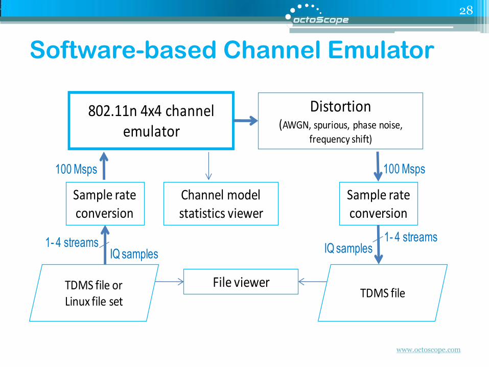
Software-based Channel Emulator
28
Sample rate conversion
802.11n 4x4 channel emulator
100 Msps 100 Msps
Sample rate conversion
Channel model statistics viewer
Distortion(AWGN, spurious, phase noise,
frequency shift)
File viewerTDMS file or Linux file set
IQ samples IQ samples1- 4 streams 1- 4 streams
TDMS file

www.octoscope.com
Channel Emulator Console
29
National
Instruments
LabVIEW
application
Graphical
programming
environment

www.octoscope.com
Viewing Input and Output Streams
30
National
Instruments
TDMS file view
TDMS = TDM streaming
TDM = technical data management

www.octoscope.com
Software Operation
33
Apply channel modeling to a block of input
samples
Add impairments
Play time reached or user interrupt
Close files; done
Sample rate conversion
Append block to waveform
array/file
LabVIEW/Wrapper
Sample rate conversion
Input MIMO streams of I/Q samples
Read block to waveform array/file
Library (Windows .dll or Linux .so)
LabVIEW/Wrapper
Create a library of waveforms in
the graphical LabVIEW
environment
Controlled channel modeling
Impairments
Waveforms can be used for
software simulation or
hardware playback
www.octoscope.com
Confidential
References
• IEEE, 802.11-03/940r4: TGn Channel Models; May 10, 2004
• Schumacher et al, "Description of a MATLAB® implementation of the Indoor MIMO WLAN channel model proposed by the IEEE 802.11 TGn Channel Model Special Committee", May 2004
• Schumacher et al, "From antenna spacings to theoretical capacities - guidelines for simulating MIMO systems"
• Schumacher reference software for implementing and verifying 802.11n models - http://www.info.fundp.ac.be/~lsc/Research/IEEE_80211_HTSG_CMSC/distribution_terms.html
• 3GPP 36-521, UE Conformance Specification, Annex B
• 3GPP TR 25.996, "3rd Generation Partnership Project; technical specification group radio access networks; Spatial channel model for MIMO simulations"
• IST-WINNER II Deliverable 1.1.2 v.1.2, “WINNER II Channel Models”, IST-WINNER2, Tech. Rep., 2008 (http://projects.celtic-initiative.org/winner+/deliverables.html)
• 3GPP TR37.976, MIMO OTA channel models
• IEEE, 11-09-0334-08-00ad-channel-models-for-60-ghz-wlan-systems
34