SoaringDigest Radio C ntrolled · Our response was relatively brief: “I’ve looked at various...
62
SoaringDigest Radio C ntrolled September 2016 Vol. 33, No. 9
Transcript of SoaringDigest Radio C ntrolled · Our response was relatively brief: “I’ve looked at various...

SoaringDigestRadio C ntrolled
September 2016 Vol. 33, No. 9

2 R/C Soaring Digest
September 2016
Vol. 33, No. 9C
ON
TEN
TSFront cover: A DragonFly flies against a stunning background of clouds. The DragonFly has a 3 meter span and is available from Valenta Models. Photo by Gary Quiring. Sony ILCE-6000, ISO 100, 1/640 sec., f11, 55mm
4 Building the Tangent Alpine 4001 ElektroGino Alongi takes the build beyond the basics.
10 Glider DollyPlans for a laser-cut dolly suitable for assisting the launch of large self-launching electrical powered models of 3-5 m wing span. Designed by Gino Alongi.
11 Customizing the Tangent ASH 26Gino Alongi moved the elevator servo to the vertical fin for direct drive and created a very detailed cockpit.
15 Three books worth owningWorkshop Practice (the English translation of Werkstattpraxis fur den Bau von Gleit- und Segelflugzeugen), ANC-18 Design of Wood Aircraft Structures, and Composite Design Manual are reviewed by Bill Kuhlman.
An Improved Aerotow Loop 20 A quick tip by Rex Ashwell.
Scenes from Retroplane 2016 21The annual event as photographed by Elia Passerini.
How I almost ripped the stabs off my Radian XL 59The altitude plot and a striking verbal description
by Ken Gantz.
Seattle Area Soaring SocietyRadian One Design Contests 61
An event suitable for any club, large or small. Information courtesy of Paul Bower.
Back cover: Geledan Regis lives in Lourdes, Pyrenées, France and took this stunning photo of his favorite slope site at Gez-ez-Angles which lies within minutes of his home. Rubis the dog is captured attentively guarding a RaceM.

September 2016 3
In the AirR/C Soaring Digest
September 2016Volume 33 Number 9
Managing Editors, Publishers Bill & Bunny (B2) Kuhlman
Contact [email protected]://www.rcsoaringdigest.comYahoo! group: RCSoaringDigest
FaceBook: https://www.facebook.com/RCSoaringDigest
R/C Soaring Digest (RCSD) is a reader-written monthly publication for the R/C sailplane enthusiast and has been published since January 1984. It is dedicated to sharing technical and educational information. All material contributed must be original and not infringe upon the copyrights of others. It is the policy of RCSD to provide accurate information. Please let us know of any error that significantly affects the meaning of a story. Because we encourage new ideas, the content of each article is the opinion of the author and may not necessarily reflect those of RCSD. We encourage anyone who wishes to
obtain additional information to contact the author.
———
Copyright © 2016 R/C Soaring DigestPublished by B2Streamlines
http://www.b2streamlines.comP.O. Box 975, Olalla WA 98359
All rights reserved
———
RC Soaring Digest is published using Adobe InDesign CS6
Although we have been followers of the annual Retroplane events for years, this edition of RCSD is the first to include coverage of one of these fun-filled get-togethers. Our sincere thanks go to Elia Passerini for the large number of exceptional photographs he submitted for publication. There were some beautiful images which did not make it into this issue but will likely find their way onto a front or back cover at some time in the future.
The Retroplane event is a showcase for RC soaring enthusiasts who go about building their own sailplanes from wood, metal tubing and fabric. The workmanship put into these models is readily apparent and most certainly appreciated by other entrants as well as the public. It is quite impressive to learn the choice of flying site is heavily dependent upon the models being able to fly at eye level, where everyone can enjoy all of the aspects involved in both the creation and flying of these realistic models.
In the same "build and fly" vein as Retroplane, please consider purchasing one or all of the books which are reviewed in this issue of RCSD. While all deal with full size aircraft, they are magnificent treatises which can be of great value to those who enjoy designing, building and flying models of wood, regardless of size.
We're still gathering material related to F3B-RES, now called F3-RES in some circles to reduce confusion. Hopefully we'll have this together in time for next month.
Time to build another sailplane!

4 R/C Soaring Digest
Gino contacted us early last year with some concerns about the downthrust built into the Tangent Alpina 34001 Elektro. as eight degrees seemed to be too large.
“I measured the offset of the original fuselage nose “cut” as Tangent produces it by laminating in a mold = - 8° from the vertical axis. It means the motor axes offset is to be fixed at this negative angle from the model zero trim. In my knowledge that is exceeding from the standards, I have ever been told to offset the motor at about 2° negative, then correct any residual pitching moment nose up by a mixer gas-elevator.
“On the other hand the Alpina 4001 Elektro has been mounted by hundreds of modelers so, there must exist a well tested setup to justify the proposal of such an offset thrust. Have you any rule for the motor offset? Can you please suggest me where can I find some information?”
Our response was relatively brief:
“I’ve looked at various web sites which feature the Alpina 4001 Elektro and I must say, the photos do show quite a bit of motor downthrust. There is a build log on RCGroups. Do a search for ‘Alpina 4001 Elektro.’
“As far as I know, there is no set rule for determining thrust offset angles, but some of the older rubber power models had quite severe angles.
“You do not want to correct residual pitching by connecting throttle to elevator! An offset thrust line is much better as the power direction is constant regardless of air speed, whereas elevator effectiveness always varies with airspeed rather than thrust. The incorporated downthrust will always be appropriate regardless of powerplant or thrust level.”
Gino was involved in a house move shortly thereafter, so it was not until mid-July of this year that we heard back.
“I finally tested my Alpina 4001 Elektro. Fantastic machine!
“Bill many thanks for your suggestions. In one of the photos seen on RCGroups, the motor downthrust angle takes origin from the point of greatest air drag : the wing focus. Thrust and drag are acting on the same axes in opposite directions.
“This idea seems to replace the missing rule on the matter... I followed it and this setup works fine!!! No pitch/gas (throttle) mixing is needed as the residual pitching moment is close to zero value, really easy to control.”
The following pages describe in photographs some of the finer points of Gino’s Alpina 4001 Elektro build.
Building the Tangent Alpina 4001 Elektro Beyond the basics
Gino Alongi, [email protected]

September 2016 5
1
1. The new Tangent “long nose” fuselage, shown at the back, is no longer an ARF product; it requires more handmade items than before. The older fuselage, front, has the nose cutout for the motor mount, and ready made air inlet and outlet. The latter is under the wing trailing edge,
2. In order to get the thrust line set up properly, a simple alignment tool is constructed. Precut the nose so it’s 1 - 2 mm longer than the final size. A PVC pattern is then forced into the fuselage. It will hold the motor frame in place while the epoxy cures. Note the tube extending back from the center of the PVC pattern. See also Photo 4.
3. The alignment hardware mount for the appropriate right and down thrust angles. See also Photo 4. 2
3

6 R/C Soaring Digest
4. The alignment tube is mounted to a threaded rod which crosses the fuselage at the center of the main spar. The thrust line thus goes through the point of maximum drag to minimize the pitching moment generated any time the motor is providing thrust. Note the alignment tube is not fixed at the center of the fuselage, but rather toward the left side. The imparted right thrust will reduce the roll moment.
4
5. With the alignment tube still in place, a disk sander can be used to carefully set the fuselage nose edge contour to the
thrust angles which have now been built in.
6 and 7. Creating the front cooling duct entailed using a homemade metal template and a small diameter diamond router bit. The resulting slots look and work great.
5
6 7

September 2016 7
8 9
8 and 9. A plywood template was used on a PVC tube to achieve the proper contour for the exhaust opening. The left piece in Photo 8 shows the penciled outline as well as the notches which allow the forward portion of the outlet to be inset in the fuselage. The finished outlet is shown in Photo 9.
10
11
10. The original length of the elevator lever was too short. It did not fit the distance between the stabilizer shaft hole and the bowden line. Used without modification, the load on the elevator servo was severe. Lengthening the arm was not difficult, just a matter of a metal extension held in place with two screws and epoxy. A bronze bushing was added to the shorter arm with the thickness of the arm increased to three layers to minimize wear.
11. Additionally, the elevator lever as received was to rotate around a threaded bronze rod, shown at the lower left of the photo. My preference is a smooth stainless steel surface, so a home made shaft holder was substituted. Much better.

8 R/C Soaring Digest
12
1412. Fuselage interior. Left to right: ESC, elevator and rudder servos, Multiplex 9-channel receiver, battery pack.
13. The battery pack mounted on a discarded helicopter blade allows for easy insertion and removal. (You can see the end of the blade screwed down to the airframe in Photo 12 directly under the red battery wire.
13
14. The fuselage interior showing the two air outlets and the bowden cables to the elevator and rudder. The perforated plate at the air exit holes holds the rear of the battery mount.

September 2016 9
15. Here’s the setup for measuring the thrust of the power unit with different batteries and propellers.
16. An Aveox 1409/2Y geared 2:38 on the testing bench.
17. Results of various tests. Test #4, noted by red arrow, shows the Aveox motor runs a 14x9,5 folding prop at 7300 rpm while absorbing 39A from a Lipo 4S. The thrust measured 3.2 Kg./7.0 lbs.
Visit Tangent Modelltechnik for complete information on the Alpina 4001 Elektro:<http://www.tangent-modelltechnik.de/TA_Alpina4001.html> or <http://tinyurl.com/zokb6k8>
15
16
17

10 R/C Soaring Digest
GLIDER DOLLY Gino Alongi, [email protected]
I recently made a new design glider dolly for self-launching electric powered models of 3-5 m wing span. It is made of laser cut 3 mm plywood and is very simple to assemble. A full size PDF pattern, as at right, can be downloaded from <http://www.rcsoaringdigest.com/Supplements/Alongi_Dolly.pdf> / <http://tinyurl.com/jtm8wys>.
Email me if you’d like to receive the DXF file for laser cutting.

September 2016 11
1. Gino innovated when it came to placing the elevator servo in his Tangent Modelltechnik ASH 26, moving it from the cockpit area to the vertical fin. This allowed a direct elevator drive. Here you see the various parts used in this modification.
2. The vertical fin spar provided in the box weighs 19 grams.
3. Gino’s replacement, which includes both the vertical fin spar and the servo mounting bracketing weighs 20 grams.
Customizing the Tangent ASH 26 elevator servo mount and cockpit detailGino Alongi, [email protected]
1
2
3

12 R/C Soaring Digest
4. The four parts are glued together, creating rigid lightweight framework.
5. The opening in the vertical fin spar allows for easy insertion of the elevator servo.
6. Once the servo is in place, the usual screw fastening system is used for retention. Note the cutout for the rudder pushrod at the left of the spar.
6. Firmly mounted in the frame, the assembly is ready to be placed within the vertical fin.
7. Here’s the elevator servo firmly set into the vertical fin. The servo can now be attached to the elevator with a straight pushrod, giving a firm and slop free control system. Note the cutout for the rudder pushrod at the lower right..
8. Once the rudder is in place, the entire elevator control system is completely enclosed.
4 5 6
7 8

September 2016 13
9. A double 2600 mAh Lipo battery was configured to fit in the nose (note the cells are offset).
10. Slipped into place, the battery pack nearly disappears. This battery pack is heavy enough that no ballast is need to achieve the appropriate CG location.
11. A very efficient placement of the battery pack, wiring, rudder
and tow release servos allows a custom cockpit to be fitted.
12. All equipment is hidden below the cockpit interior.
9
10
11
12

14 R/C Soaring Digest
13 - 15. These photos show the cockpit details of Gino’s Tangent Modelltechnik ASH 26. Gino assembled some of the cockpit interior with readily available retail parts, like the instruments and the microphone, but most of the pieces were made or assembled from small parts - pins, LEDs, etc. The seat upholstery was sewn by Gino’s wife.
All it needs now is a realistic pilot!
13 14
15

September 2016 15
I have been building RC sailplanes for more than a half century and so have seen many advancements in radio equipment and model aircraft aerodynamics.
I’ve also witnessed the tremendous changes in construction materials and methods which have come about because of the available technologies and the drive toward greater performance.
Being the eclectic enthusiast that I am, my aeromodeling interests range from F1A (outdoor free flight towline glider)
and F1D (indoor rubber free flight) through all of the AMA and FAI RC sailplane classes.
My building projects have included stick and tissue models, hand launched free fight gliders, small and large powered RC aircraft, and a large number of “wood wing” and composite - foam/fiberglass/carbon - RC sailplanes.
In looking back over this history, I have long realized that my first love has always been models built primarily of wood, although composite construction has its own benefits which I appreciate.
Workshop Practice Neal Pfeiffer and Simine Short, Editors
When I was made aware of the availability of the classic “Werkstattpraxis fur den Bau von Gleit- und Segelflugzeugen” by Hans Jacobs and Herbert Luck in an English translation, I eagerly awaited its publication.
First made available at the Vintage Sailplane Meet in Elmira New York on July 11th of this year, “Workshop Practice for Building and Repairing
Three books worth owning
Reviewed by Bill Kuhlman, [email protected]

16 R/C Soaring Digest
Wooden Gliders and Sailplanes” is the culmination of a 25 year project by a large number of volunteers under the auspices of the Vintage Sailplane Association.
The first German edition of this book was published in 1932 and came about as a result of the huge and growing sport of soaring in this pre-war decade. Subsequent editions with updates were published as late as 1955, always in German. The author, Hans Jacobs, was a tremendously influential sailplane designer, having
created the Weihe, Meise, Kranich, Habicht and others, and the influence of his book was more than substantial.
While this book was originally (and still is) aimed at those who are restoring or building wood sailplanes, whether original vintage, replica, or new design, there is sufficient information here to augment the knowledge base of any designer and/or builder of wood models.
Divided into eleven chapters (one being an Appendix devoted to German glider types, the book is well organized and is easily searched despite not having a separate formatted index, only a well detailed Table of Contents.
As would be expected from a book like this, there is plenty of material devoted to wood itself. The composition and properties of wood is covered in detail. Starting with wood cell
structure, the reader is lead through compression and tension strength relative to grain direction, engineered wood and plywood. With this basis, various glue types are covered next. Steel sheet, steel tubing, cable splicing and fabrics are also covered.
Working with these various materials sometimes calls for specific working methods, including joining wood strips and plywood sheets, welding and riveting, forming aluminum and transparent plastics, etc.
Following this, Chapter 6 is devoted to actual construction methods: various types of wing ribs and the jigs which make this process go more quickly; solid, I-beam, box and block spar construction; control horns; tip bows and trailing edges; corner and curved fuselage frames and trusses.
The assembly of various parts into a cohesive whole is described relative to the individual components. Of particular interest is the construction of large jigs to assure accurate wings. The “vertical” method of wing assembly is highlighted as it makes installation of a plywood D-tube easier.
Various adjustable fuselage fixtures are also described.
For the scale modeler, the section on canopy construction will be of interest. Latch mechanisms and several methods of fastening the glazing to the frame are well illustrated. This section also has a very good description of the design and construction of steel tube fuselages.
The last part of this section covers instrumentation and describes in some detail how various components operate.
The Appendix is devoted to an overview of German gliders and sailplanes of the time. Thirteen models, from the SG-38 (1933) through the Kranich III (1950), are detailed in a table and there are 3-views, a photo, and a general description of each.
Rounding out this volume is a rather extensive update which is presented to inform restorers of the various changes in

September 2016 17
technology which have come about in the years between the German publication of the book and this translation. Written by Neal Pfeiffer, this section describes updates to workshop safety, various wood species which are now more readily available, scarf joints for spar repair, modern adhesives, fiber-reinforced plastics, fabrics and paint.
I am very impressed by this book, not only for the informational materials it contains, but also by the tremendous amount of work put in by the VSA team in accurately translating the text into a tremendously readable form and publishing it for the benefit of all English speaking enthusiasts.
This is a hardbound book of 384 6" x 9.25" pages. The cover is full color, the interior includes easily read text, and there are 338 black and white figures and grayscale photographs. Price is $47 (US) or €45 (Europe) plus shipping and handling. It’s available from the Vintage Sailplane Association <http://www.vintagesailplane.org> and Cumulus Soaring <http://www.cumulus-soaring.com> in the United States, and EQIP <http://www.eqip.de> in Germany.
ANC-18 Design of Wood Aircraft Structures United States government agencies
Originally published in 1944 and updated in 1955, this U.S. government publication is a wealth of information relevant to aircraft of wood construction.
Both editions are freely available in PDF form and have made the rounds of various internet forums, in addition to being available through a few aviation information portals. More recently, the original 1944 edition has been made available again in printed form through a “print on demand” service based in India.
Originally available through the United States Government Printing Office, this volume was the product of a number of departments, including the War Department, the Navy Department, and the Department of Commerce. It was issued by the Army-Navy-Civil Committee on Aircraft Design Criteria, under the supervision of the Aeronautical Board.
Written for use in the design of both military aircraft, it contains material which is acceptable to the Army Air Force, the Navy Bureau of Aeronautics, and the Civil Aeronautics Administration of the time. There are three chapters of information following the first chapter introduction with nomenclature and definitions of symbols.
Chapter 2 describes the strength of wood and plywood elements. This includes both basic strength and elastic properties, together with testing methods. Of special note is the treatment of compression, tension and torsion as applied to spar design.
Ninety pages are devoted to the characteristics of plywood, predominantly 3, 5 and 7-ply, although 9 and 11-ply are also mentioned. This portion of Chapter 2 includes a large number of illustrations and tables and details the characteristics of plywood (compression, tension and shear) with special

18 R/C Soaring Digest
attention to those cases when the grain is oriented at 45 degrees. The latter portion of this chapter deals with the use of plywood in curved panels and various methods of joining.
Chapter 3 describes the methods for structural analysis. Here there is an explanation of the methods appropriate for determining the internal stresses which result from external loads to wood and plywood aircraft structures. This portion begins with an examination of wings, and covers not only spar systems but also ribs, reinforced shell and fabric covered wings. Included forces are shear, bending moment, compression and tension.
There are numerous tables, formulae and graphics to assist in understanding the roles of the various components in handling the impinging loads. The section of this chapter dealing with fuselages describes four-longeron, reinforced shell, and pure shell (monocoque) types.
Of particular interest to the scale modeler will be Chapter 4. Here the details of structural design are outlined. Here there are numerous line drawings which show how best to make scarf joints and lap splices, hinge cutouts, beam (spar) construction, gusseting, canted ribs, fuselage bulkheads, attaching metal fittings to wood parts. The end of the chapter depicts a number of illustrated examples of actual design details.
ANC-18 is an excellent complement to “Workshop Practice” as it provides, as the title suggests, the information and data required to design airworthy structures of wood, while “Workshop Practice” is a more basic treatise on working with the wood aircraft structures themselves.
ANC-18 is another example of a well organized volume which does not have a dedicated index. Rather, each chapter begins with a detailed outline of the contents of that section, and all is arranged in logical order.
For those interested, we’ve made both the 1944 (247 pages)
and 1951 (234 pages) editions of ANC-18 available for downloading from the RC Soaring Digest web site: 1944 edition <http://www.rcsoaringdigest.com/Supplements/ANC-18_1944.pdf> (18.1MB), 1951 edition <http://www.rcsoaringdigest.com/Supplements/ANC-18_1951.pdf> (11.6MB). The two available editions differ in format, with the 1944 edition being predominantly a single column layout, while the 1951 edition utilizes a two column format.
The 1944 edition is available in printed form (print on demand), 7.5" x 10", for under US$15, postage included, from a firm in India. A softcover version is under $13, while US$14 and a few cents will get you the same book in hardcover with a very nice dustcover included. We own the hardcover version and it is very well done, with the exception that odd numbered pages are on the left rather than the right. Please contact us at <[email protected]> for information on obtaining the printed volume.
Composite Design Manual JIm Marske
Well known for his work with numerous full size tailless sailplanes, including the Pioneer and Monarch series and the Genesis, Jim Marske is also a supplier of Graphlite Carbon Rod to amateur aircraft builders. In 2009, JIm published this book which includes using Graphlite products for wing spar caps, complete with all of the necessary calculations for determining how much material is needed to sustain given loads.
This volume goes even further than expounding on Graphlite products and their application. It describes not only the various wing and spar design calculations, but plug and mold making, wing attachment methods, and the use of composite materials in rib construction. It essentially documents Jim’s more than 50 years of experience working with composites.

September 2016 19
Filled with color photos of aircraft construction process and with extensive use of illustrative diagrams, this volume is a tremendously useful handbook for anyone working with composites. All components of a composite structure - carbon rods and fabrics, fiberglass, and resin - are
described with relevant strength and weight data as well as supplier suggestions. And Jim has included recommendations for post cure of epoxies. This topic is seldom covered in other publications devoted to composite construction.
Structure loading is described in line with real world examples, explained with a large number of line drawings and relevant formulae, and solutions are examined in detail. Calculations for strutted wings are included, as are the calculations necessary for the struts themselves.
The chapter on plug and mold making covers plug construction methods, hot wire foam cutting, joining and bonding mold parts, fabric overlap, and there is even a section on making
composite tubes. Various techniques for vacuum bagging specific parts are described in detail with excellent illustrations.
The section on wing attachment methods is especially intriguing as it describes several methods used by full size manufacturers which can be easily copied by scale modelers as appropriate.
In examining composite ribs, Jim talks about the stresses on the ribs and methods of composite rib construction.
This book consists of 80 plus 8.5" x 11" pages, all printed on one side of the sheet, and spiral bound. This makes it ideal for workshops where builders are continually looking for specific guidance as they go along.
Previously only available to participants of the Marske Aircraft Composite Design Seminar and Workshop, this official workshop design manual is now available for purchase due to overwhelming request.
It is available directly from Jim Marske via the Marske Aircraft web site <http://www.marskeaircraft.com/flying-wings.html>. Cost is US$56 within the United States and US$81 elsewhere, shipping included.
__________
Any aeromodeller involved in wood and/or composite construction will benefit from owning one or all of these volumes.
All are readily available (both editions of ANC-18 as PDF files, plus the 1944 edition as print on demand), and are priced competitively. We have no reservations in recommending any of these volumes for purchase for personal and club libraries.
20 R/C Soaring Digest
When I first started aerotowing a couple of years ago, all the local participants were using a simple loop of monofilament as the connection between the glider and the towline, and this seems to be what most still use.
It’s a low cost and simple answer to the problem, but one that I’ve always struggled to connect to my gliders, especially if I’m in a hurry.
The problem is compressing the loop down to slide into the tow release tube — it does its best to escape all the time or the resultant loop twists sideways and doesn’t want to hook up. I use the Hobby King tow release units and if the loop doesn’t slide into place properly, the hook can close on the monofilament, pinching it in place without hooking up and sometimes nicking the nylon.
I’ve come up with a low tech solution that has worked faultlessly for me and thought to share it with anyone else having similar problems.
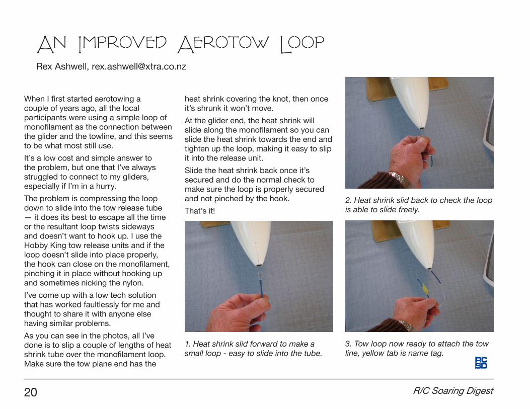
As you can see in the photos, all I’ve done is to slip a couple of lengths of heat shrink tube over the monofilament loop. Make sure the tow plane end has the
heat shrink covering the knot, then once it’s shrunk it won’t move.
At the glider end, the heat shrink will slide along the monofilament so you can slide the heat shrink towards the end and tighten up the loop, making it easy to slip it into the release unit.
Slide the heat shrink back once it’s secured and do the normal check to make sure the loop is properly secured and not pinched by the hook.
That’s it!
An Improved Aerotow Loop
3. Tow loop now ready to attach the tow line, yellow tab is name tag.
1. Heat shrink slid forward to make a small loop - easy to slide into the tube.
2. Heat shrink slid back to check the loop is able to slide freely.
Rex Ashwell, [email protected]

September 2016 21
Scenes from Retroplane 2016
Text and photos by Elia Passerini, [email protected]
I am pleased to send you some photos taken by me at the “Retroplane” meeting held in Polsa (Italy) on 16 and 17 July.
Polsa is situated at 1300 meters altitude in the Italian Pre-Alps which divide the Lake Garda with the valley of the Adige River. The nearest towns are Rovereto, Trento and Verona South.
— Elia
Retroplane event information from <http://www.retroplane.net/retroplane2016/index-it.htm>
RETROPLANE is a gathering reserved for the flight of models of glider models of vintage prior to 1960, the year preceding the arrival of the gliders made of composite materials. Models should correspond STRICTLY to these criteria.
This meeting is organized for the pleasure of bringing together passionate builders and lovers of original models. Only models personally made of wood and fabric or metal tubing are considered.
This meeting is organized at a location where models fly at eye level for the pleasure of watching these magnificent models, admiring the transparency of glazing and hearing the whistle of the models in the air.
RETROPLANE takes place every year in a different region or in a different country.

22 R/C Soaring Digest

September 2016 23

24 R/C Soaring Digest

September 2016 25

26 R/C Soaring Digest

September 2016 27
Ciani EC 38/56 Urendo, Italy, 1956

28 R/C Soaring Digest
Caproni Vizzola 2, Italy, 1937/38

September 2016 29

30 R/C Soaring Digest

September 2016 31
GO3 Minimoa, Germany, 1935

32 R/C Soaring Digest
Hall Cherokee II, USA, 1956

September 2016 33

34 R/C Soaring Digest
Hall Cherokee II, USA, 1956

September 2016 35

36 R/C Soaring Digest

September 2016 37
Slingsby T-31 Tandem Tutor, Britain, 1950

38 R/C Soaring Digest

September 2016 39

40 R/C Soaring Digest
Wien, Germany, 1929

September 2016 41

42 R/C Soaring Digest

September 2016 43
CVV3 - Arcore, Italy, 1938

44 R/C Soaring Digest
IS–B Komar, Poland, 1933

September 2016 45

46 R/C Soaring Digest

September 2016 47

48 R/C Soaring Digest

September 2016 49

50 R/C Soaring Digest
Schweizer SGU 1-7, USA, 1937

September 2016 51

52 R/C Soaring Digest

September 2016 53

54 R/C Soaring Digest

September 2016 55
VSB 37, Czech Republic, 1937

56 R/C Soaring Digest

September 2016 57

58 R/C Soaring Digest
A Fournier, just landed, with the city of Rovereto in the background.

September 2016 59
This is how I almost ripped my stabs off the RXL yesterday.
I was having a difficult time seeing the RXL at 1200+ feet, so I wanted to come down a little and ride back up if I could.
I remember putting the spoilers out and it seemed to come down as expected.
I then started flying normally again and remember the RXL pointing straight at me when I had trouble seeing it again.
I did what I’d normally do and just kept my hands off of everything until I spotted it again.
I spotted the RXL because it was making a buzzing sound and the aft end looked blurry when I did spot it again.
I think the back end was fluttering and that’s what caught my attention.
Looks like it was descending at 32 ft/sec for almost 18 seconds.
Seems like once I hit the 1000 ft mark with any airplane I start to get nervous
about going higher yet always manage to make things worse by descending too quickly.
I have to work on that!
RADIAN XLKen Gantz, [email protected]
how I almost ripped the stabs off my

60 R/C Soaring Digest
Seattle Area Soaring Society’s
Radian One Design Contests
The first weekend of the month is the date for the Seattle Area Soaring Society Radian One Design Contest, May through October.
These contests, CD’d by Paul Bower, are low key affairs held at the SASS flying site in Carnation or at 60 Acres in Redmond. Divided into Novice and Expert classes (and sometimes Competitor), these events are fun-filled events with a joke contest and on-field barbecue supplied by Bret Sutton.
Competition is sometimes tough due to weather conditions - relatively cool overcast days, wind - but that doesn’t dampen the enthusiasm.
Participation varies between a half dozen and more than a dozen, with the ages of those in attendance varying widely. A number of SASS members come to these events just for the social aspects. It’s not unusual for one or two to leave their sailplanes at home and simply enter the joke contest! Yes, there’s a trophy for that!
There are still two Radian One Design Contests to be held this year, September 3 and October 1. Entries are specifically limited to the Standard Parkzone Radians using elevator, rudder, and throttle controls. Pilot Meeting is at 9:30 AM, and the contests run from 10:00 AM until 4:00 PM. AMA membership is required, of course.
For more information contact CD Paul Bower at <[email protected]>
Youngest SASS Radian One Design contestant, Charlie Keeffe

September 2016 61
2016 CONTESTS - OPEN TO EVERYONE First Saturday of Every Month 60 Acres (Redmond) & Carnation Farm
May 7 June 4 July 2 Aug 6 Sept 3 Oct 1 60 Acres Carnation Carnation 60 Acres 60 Acres Carnation
LOW KEY, FUN Radian Contest & Get-together Novice and Expert flying classes / Joke contest Std Parkzone Radians only (elev, rud, throttle) 10am-4pm(9:30 mtg) AMA membership req’d
Contact Contest Director Paul Bower at [email protected] for more details
RADIAN ONE DESIGN CONTEST Seattle Area Soaring Society
seattleareasoaringsociety.com
June 2016 event participants
July 2016 event participants