Snap Fit Design
4
Snap Fit Design Snap fits are commonly used as an assembly method for injection molded parts. Although they have been around for many years, they have recently become more important in an attempt to simplify assembly and its associated costs. Snap fits are very useful because they eliminate screws, clips, adhesives, or other joining methods. The snaps are molded into the product, so additional parts are not needed to join them together. Additionally, if designed correctly, they can be disassembled and reassembled several times without any problems. A snap fit can either be designed as a permanent snap or a multiple snap. Permanent fits are used in disposable parts that are never meant to be disassembled. Multiple snaps are used in most designs where disassembly for service is expected. There are complications associated with snap fits. A lot more engineering is required to design a proper snap fit than designing something for screw assembly. Snap fits can also make the injection mold that produces the parts significantly more complicated and expensive. Generally, the savings in assembly costs more than makes up for added cost and complexity of the mold. There are three main types of snap fits: annular, cantilever, and torsional. Annular Snap Fits Figures 1 through 3 show examples of annular snap fits. Because there is so much hoop strain when the parts are assembled, usually only materials with a large elongation at yield are able to be used. See the calculation section for formulas to calculate the maximum deflections of the fit. Cantilever Snap Fits Cantilever snap fits are the most widely used type of snap fit. There is a considerable amount of calculation and engineering that goes into designing a good snap fit; this section will show different design techniques. Refer to the calculation section to find the specific dimensions for the cantilever. Figure 4 shows four different methods of designing snap fits for disassembly. Figure 4a shows a snap fit with a 90° hook and a 90° recess; this permanent fit cannot be disassembled. Figure 4b uses an angled surface for both the assembly and disassembly portions of the cantilever and the recess. The cap can be removed with the same force used in assembly. Figure 4c has the same 90 angles as 4a, but the designer put a window in the side to allow the snap fit to put disengaged for disassembly. Figure 4d uses a U type beam to disengage the snap from the outside. A potential problem with the design shown in Figure 4c is that the snap fit can be pushed too far; Figure 1: A pen sometimes utilizes an annular snap fit to retain the cap. Figure 2: This bottle cap uses an annular snap fit. Figure 3: A ball and socket joint is a kind of annular snap fit. Page 1 of 5 Snap Fit Design
-
Upload
sameer-malik -
Category
Documents
-
view
409 -
download
2
Transcript of Snap Fit Design
Snap Fit Design Snap fits are commonly used as an assembly method for injection molded parts. Although they have been around for many years, they have recently become more important in an attempt to simplify assembly and its associated costs. Snap fits are very useful because they eliminate screws, clips, adhesives, or other joining methods. The snaps are molded into the product, so additional parts are not needed to join them together. Additionally, if designed correctly, they can be disassembled and reassembled several times without any problems. A snap fit can either be designed as a permanent snap or a multiple snap. Permanent fits are used in disposable parts that are never meant to be disassembled. Multiple snaps are used in most designs where disassembly for service is expected. There are complications associated with snap fits. A lot more engineering is required to design a proper snap fit than designing something for screw assembly. Snap fits can also make the injection mold that produces the parts significantly more complicated and expensive. Generally, the savings in assembly costs more than makes up for added cost and complexity of the mold. There are three main types of snap fits: annular, cantilever, and torsional. Annular Snap Fits
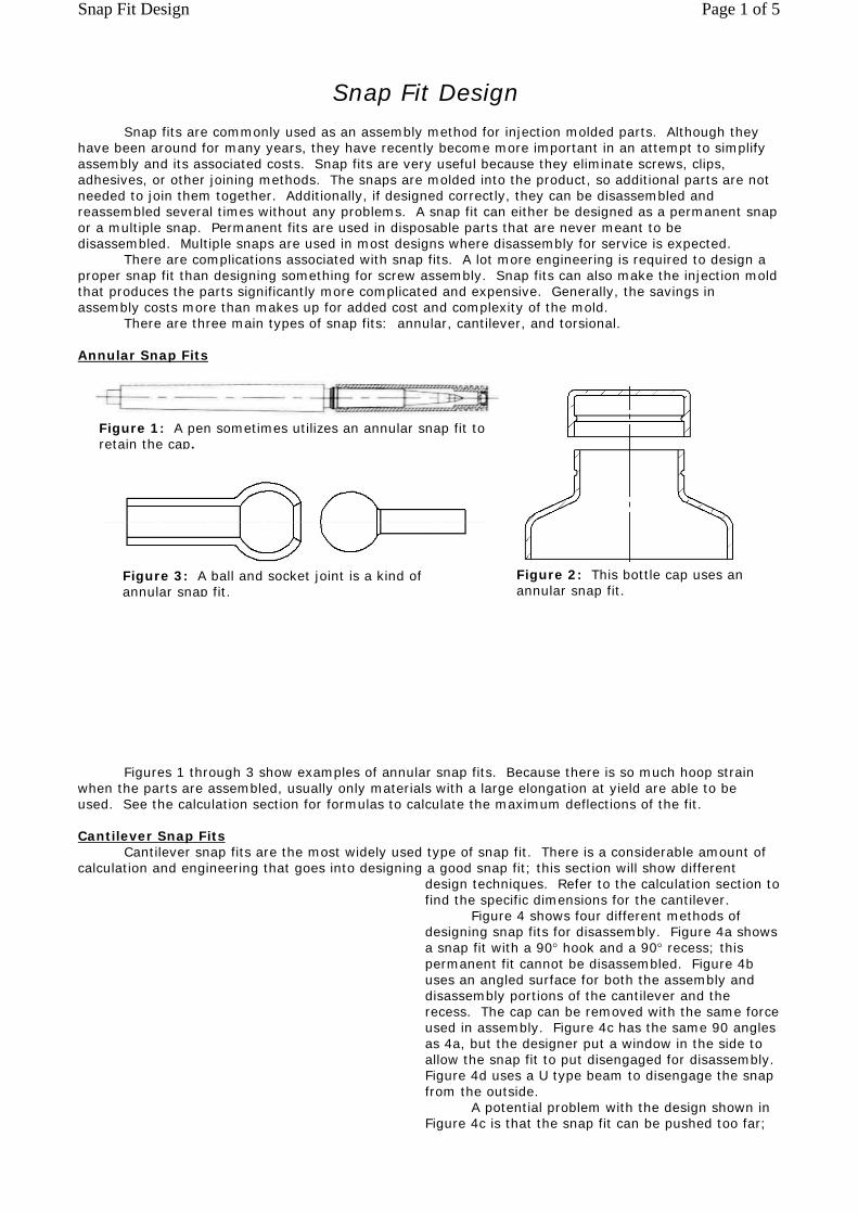
Figures 1 through 3 show examples of annular snap fits. Because there is so much hoop strain when the parts are assembled, usually only materials with a large elongation at yield are able to be used. See the calculation section for formulas to calculate the maximum deflections of the fit. Cantilever Snap Fits Cantilever snap fits are the most widely used type of snap fit. There is a considerable amount of calculation and engineering that goes into designing a good snap fit; this section will show different
design techniques. Refer to the calculation section to find the specific dimensions for the cantilever. Figure 4 shows four different methods of designing snap fits for disassembly. Figure 4a shows a snap fit with a 90° hook and a 90° recess; this permanent fit cannot be disassembled. Figure 4b uses an angled surface for both the assembly and disassembly portions of the cantilever and the recess. The cap can be removed with the same force used in assembly. Figure 4c has the same 90 angles as 4a, but the designer put a window in the side to allow the snap fit to put disengaged for disassembly. Figure 4d uses a U type beam to disengage the snap from the outside. A potential problem with the design shown in Figure 4c is that the snap fit can be pushed too far;
Figure 1: A pen sometimes utilizes an annular snap fit to retain the cap.
Figure 2: This bottle cap uses an annular snap fit.
Figure 3: A ball and socket joint is a kind of annular snap fit.
Page 1 of 5Snap Fit Design

there is no stop. If a snap fit breaks, it is usually impossible to repair it, so designers will commonly put a stop behind it to prevent it from being overstrained. Figure 4d's design has a stop incorporated into the design (the cantilever can only be pushed so far).
Figure 5 shows the mechanism of a cantilever snap fit, and how both assembly and separation can be achieved by using angled surfaces on the snap and the engaging piece of the recess.
U shaped cantilever snap fits are commonly used in such places as battery doors and covers. Figure 6 shows how this type of snap fit works. With this type of snap fit, the plastic does not experience a lot strain, so multiple flexes are possible without damaging the plastic beam. It also has a built-in stop, so the beam cannot be flexed too much and damaged.
A problem with joining two plastic pieces together is holding a high tolerance on the snap fits so that a tight fit is achieved. With snap fits, when joining two pieces together as shown in Figure 7, there is no way to get any preload on the cantilever snap. This is a major disadvantage of using snap fits over screws. One way to get around this is to sandwich an elastomeric materials between the mating pieces, as shown in Figure 7. The plastic pieces are pressed together, compressing the elastomeric component and engaging the snap fit. The compressed component acts as a spring and gives preload to the snap, resulting in a tight assembly. The elastomeric component can also act as a gasket to keep out dust, water, or other contaminants.
Figure 4: These four snap fit designs allow different types of disassembly.
Figure 6: The stages of a U shaped cantilever snap fit.
Figure 7: An elastomeric material can be used to seal and tighten the fit between mating parts.
Figure 5: Angled surfaces are used so assembly and disassembly can be accomplished conveniently with opposite forces.
Page 2 of 5Snap Fit Design
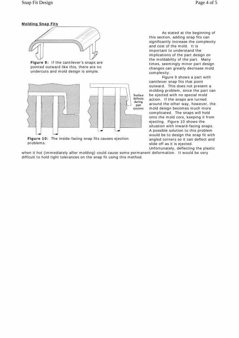
Molding Snap Fits As stated at the beginning of this section, adding snap fits can significantly increase the complexity and cost of the mold. It is important to understand the implications of the part design on the moldability of the part. Many times, seemingly minor part design changes can greatly decrease mold complexity. Figure 9 shows a part with cantilever snap fits that point outward. This does not present a molding problem, since the part can be ejected with no special mold action. If the snaps are turned around the other way, however, the mold design becomes much more complicated. The snaps will hold onto the mold core, keeping it from ejecting. Figure 10 shows the situation with inward-facing snaps. A possible solution to this problem would be to design the snap fit with angled corners so it can deflect and slide off as it is ejected. Unfortunately, deflecting the plastic
when it hot (immediately after molding) could cause some permanent deformation. It would be very difficult to hold tight tolerances on the snap fit using this method.
Figure 9: If the cantilever's snaps are pointed outward like this, there are no undercuts and mold design is simple.
Figure 10: The inside-facing snap fits causes ejection problems.
Page 4 of 5Snap Fit Design

A similar problem is experienced with an internal snap fit. As seen in Figure 11, this part cannot be ejected with simple ejection methods. A mold component called a lifter is required to release the snap during ejection. The back of the lifter is attached to a slide on the ejector plate. During ejection, the ejector plate moves forward, forcing the lifter forward as well. The lifter travels along an angled mold surface and releases the snap fit once it moves out far enough. Although it is fairly simple, the addition of lifters to a mold can greatly increase its cost, and should be avoided if possible. Also note that the lifter travels across the surface of the part during ejection. There cannot be any part features in this area because they will get in
the way of the lifter. An easy and elegant way to eliminate the need for a lifter to release a snap fit is to put a window at its base, as shown in Figure 12. The window eliminates the undercut formed by the hook, and allows the hook to be formed by the cavity side of the mold. Figure 13 shows a cross section of the mold at the window. The underside of the snap is formed through the slot. This mold does not require any special type of ejection. This design can
only be used on a part where a hole in the surface is not functionally or aesthetically undesirable.
( Figures 1 comes from Paul A. Tres's book "Designing Plastic Parts for Assembly 2nd,Revised Edition." You can purchase his book at http://ets-corp.com/lectures/dppa/dppa.htm . )
Figure 11: An internal snap fit requires a lifter to eject it.
Figure 12: A window at the base of a cantilever snap fit eliminates the undercut.
Figure 13: A mold cross section at a snap fit shows how a window eliminates the need for a lifter.
Page 5 of 5Snap Fit Design


![Snap-Fit Latch Design - Solvay · 2020. 10. 31. · 3 \ Snap-Fit Latch Design Figure 4: Typical stress/strain curve for an unfilled ductile resin Stress [ kpsi ] 12 11 10 9 8 7 6](https://static.fdocuments.us/doc/165x107/60ba5ec844f59323157ea20c/snap-fit-latch-design-solvay-2020-10-31-3-snap-fit-latch-design-figure.jpg)