
Smoke Control Systems Introduction and Commissioning NEBB 2010 Semi-Annual Recertification Presented...
84
Smoke Control Systems Introduction and Commissioning NEBB 2010 Semi-Annual Recertification Presented By: Matt Donahue, P.E. January 20, 2009
-
Upload
kimberly-hall -
Category
Documents
-
view
228 -
download
4
Transcript of Smoke Control Systems Introduction and Commissioning NEBB 2010 Semi-Annual Recertification Presented...
Smoke Control SystemsIntroduction and Commissioning
NEBB 2010 Semi-Annual Recertification
Presented By: Matt Donahue, P.E.
January 20, 2009
Agenda
• Codes related to Smoke Control and Design Guides
• System Concepts
• Smoke Control System Information – Using Documents
• Commissioning
Requirements and Standards• International Building Code, Section 909
– Formerly 1994 & 1997 UBC Section 905– California Building Code
• NFPA 92A - Standard for Smoke Control Systems Using Barriers and Pressure Differences
• NFPA 92B - Standard for Smoke Management in Malls, Atria, and Large Areas

Design References
• Design of Smoke Management Systems
–Klote & Milke• ICC Guide to Smoke Control
–Evans & Klote• NFPA 92A & 92B• National Resource Council of Canada

Types of Systems Required
• The IBC requires systems to be installed or provided for certain special uses or occupancy types.
• IBC refers designer to Section 909.
• There are no specific types of systems required by Code.
• Type is based on a Rational Analysis.
International Building Code• Smoke Control Required For:
–Atrium (Section 404.4)–Enclosed Malls when Atrium qualifications
are met (Section 402.9)–Some Underground Buildings (Section
405.5)–Smokeproof Enclosure design options
(Sections 1019.1.8 and 909.20)–Stages, in lieu of roof vents (Section
410.3.7.2)

Other Requirements
• May be required by local (or state) ordinances for all high-rise buildings - carry-over from previous codes.
• Timed egress studies.
• Smoke protected seating allowances.
• Alternate Materials and Method Requests.
Smoke Control System Concepts Introduction
• It is important to recognize that these systems are not intended for:– Preservation of contents.– Timely restoration of operations.– Assistance in fire operations/overhaul.
• They are intended to:– Manage where smoke goes and where smoke does not go.– Maintain a tenable environment by limiting the spread of
smoke to areas outside the zone of origin (IBC 909.1). They do not always maintain a tenable environment in the smoke control zone of fire origin.
Smoke Control System Concepts
• “Passive” vs. “Active” Smoke Control
• Smoke Barriers, Zone Boundaries and Opening Protection
• Stairwell Pressurization – “Smokeproof” Enclosures”
• Types of Mechanical Smoke Control Systems

Passive vs. Active Control
• “Passive” uses building construction to limit the spread of smoke in a structure.
• “Active” uses mechanical equipment to control the spread of smoke in a structure. Defined as mechanical systems by Code and include pressurization method, airflow method and exhaust method.

Passive Smoke Control• Previously known as “compartmentation”.• When active is not feasible (small rooms,
no make-up air, unoccupied areas)• Depends upon location within zone.• May be separate zone or part of the same
zone (sub-zone).• If entirely bounded within a zone, no
pressure difference can be obtained between the active and passive zone.
Smoke Barriers• Used to separate smoke zones: 1-hour
rated wall construction, outside wall to outside wall.
• Leakage area ratios–walls 0.00100–exits 0.00035–other shafts 0.00150– floors and roofs 0.00050–openings determined by area

Opening Protection in Barriers• Automatic closing (Self-closing OK in
many normally closed applications).
• Tight fitting smoke and draft control.
• 20-minute rating for doors.
• Gasketing - top, sides, and sill.
• Smoke/fire dampers at HVAC openings, Class II minimum leakage rating, 250 oF (121 oC) thermal release.
Opening Protection (cont.)• Combination Fire/Smoke Dampers:
– When a fire damper is used within ductwork on a smoke control system, the operating temperature is required to be at least 50F (10C) above the maximum smoke control temperature or a maximum of 350F (177C).
– This is to ensure the damper will not close prematurely when the system is operating in the smoke control mode.

“Smokeproof” Enclosures
• Significant Changes to previous Code approaches used.
• Multiple Design Options Now Available:–Natural ventilation alternative (909.20.3)–Mechanical ventilation alternative
(909.20.4)–Stair pressurization alternative (909.20.5)
Natural Ventilation
• Open exterior balcony or vestibule with opening 16 sq. ft. in area facing an open area that is at least 20 ft. in width.
• Stair enclosure separated from building.

Mechanical Ventilation• Stair Shaft Pressurization –
+0.10”w.c. (25 Pa) from stair to all vestibules.
• Relief vent at top of stair shaft adjusted to maintain +0.10” w.c. pressure in stair shaft.

Mechanical Ventilation (cont.)
• Vestibule Ventilation – One air change/minute supply with exhaust at least 150% of supply.– Engineered system sized to provide 90
air changes per hour serving up to three vestibules simultaneously.
– Smoke trap in vestibule, ceiling at least 20” above door.
Mechanical Ventilation (cont.)
• Vestibule Ventilation (continued)– Supply air within 6” of floor level.– Exhaust air entirely within the smoke trap
and not more than 6” down from the top of smoke trap.
– No dampers required in system, unless engineered so.

Stair Pressurization
• Only in fully sprinklered buildings.
• Vestibules are not required.
• Stair Shaft Pressurization – +0.15”w.c. (37 Pa) minimum up to +0.35”w.c. (87 Pa) maximum to all vestibules.

Stair Pressurization (cont.)• Major Considerations:
– Beware of door opening force limitations!– Consider maximum stack effect
pressures, temperature gradients.– Tested with all doors closed.– No relief vent required at top of shaft, but
may enhance system operation and balance system operation.
– Difficult to achieve in tall buildings with a single zone in stairway.
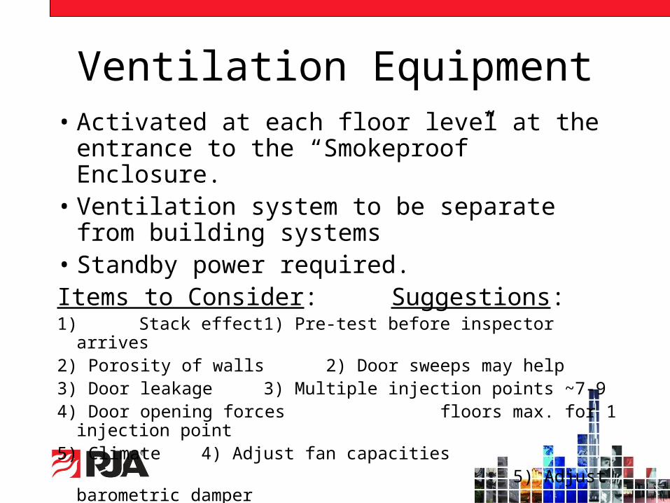
Ventilation Equipment• Activated at each floor level at the entrance to
the “Smokeproof” Enclosure.• Ventilation system to be separate from building
systems• Standby power required.Items to Consider: Suggestions:1) Stack effect 1) Pre-test before inspector
arrives2) Porosity of walls 2) Door sweeps may help3) Door leakage 3) Multiple injection points ~7-9 4) Door opening forces floors max. for 1 injection
point5) Climate 4) Adjust fan capacities 5) Adjust barometric damper

Mechanical Smoke Control• Pressurization is default design method in
IBC.• Exhaust can be used with the approval of
the AHJ.• When is one is better than the other?
– Exiting considerations.– Building configurations.– Zone boundaries.

Mechanical Smoke Control• Typical Uses of Active Systems:
– Pressurization – enclosed spaces, office areas, residential corridors, where no make-up air is provided.
– Exhaust – large open spaces (atrium, mall, etc.) where make up is available or the zone is not completely bounded by walls.
– Air Flow – protection of openings that do not have physical protection.
– Modified type systems.

Design Options
• IBC 909.6 “Pressurization Method” and NFPA 92A - Enclosed spaces, pressure differential developed for containment.

Pressurization Method
• Pressure difference across barrier at least 0.05-inch water column (12 Pa) for sprinkler protected buildings.
• Twice the maximum calculated pressure differential produced by the design fire in sprinkler protected buildings.
• Maximum pressure dependent on door opening forces.
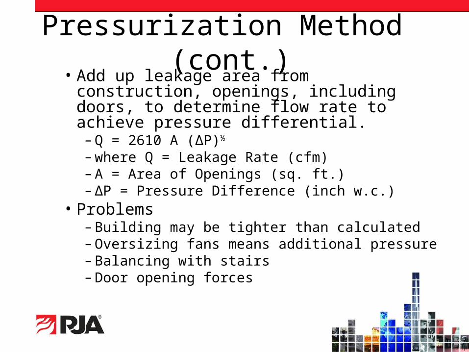
Pressurization Method (cont.)• Add up leakage area from construction,
openings, including doors, to determine flow rate to achieve pressure differential.
– Q = 2610 A (ΔP)½
– where Q = Leakage Rate (cfm)– A = Area of Openings (sq. ft.)– ΔP = Pressure Difference (inch w.c.)
• Problems– Building may be tighter than calculated– Oversizing fans means additional pressure– Balancing with stairs– Door opening forces

Door Force Calculations• The opening force for doors at smoke zone
boundaries is limited to no more than 30 lbs. (Some jurisdictions limit the opening force to no more than 15 lbs.).
• The opening force is determined by the force to overcome the closing device and the pressure against the door.
• The larger the door or the greater the pressure difference, the more the opening force will be.

• IBC 909.8 “Exhaust Method” and NFPA 92B - Open spaces, smoke exhaust to maintain smoke layer above people on highest occupied level.
Exhaust Method• Useful for large enclosed volumes.• Maintain smoke 6 ft. above highest
walking surface in the zone (previously 10 ft.)
• Natural or mechanical supply equal to or slightly less than exhaust (85% is general rule of thumb).

Exhaust Method (cont.)• Maximum velocity of air supply
toward the fire is limited to 200 fpm.– May affect plume geometry and
increase air inducted into the plume.• Plume types - must consider the
type:– Axisymmetric– Balcony spill– Window

Make Up Air
• The IBC requires make up air to be provided for exhaust method systems.
• Required to be introduced at a rate slightly less than the exhaust rate and cannot exceed 200 feet per minute towards the fire.
• As indicated before, the typical rule of thumb is to provide at least 85 percent of this make up air either by mechanical or natural means. The other 15 percent can be obtained through infiltration (building leakage).

Make Up Air (cont.)
• Make up air for high volume rate systems can be difficult to provide given building geometry and configurations.
• An exhaust rate of 200,000 cfm requires up to 850 square feet of free openings to meet the 85 percent rule. That equates to 85 linear feet of 10 foot high openings!

Make Up Air (cont.)• Make up air needs to be introduced below the
smoke layer. If an exhaust system is being provided for a multi-level space (such as an atrium) the make up air can be introduced at multiple levels, thereby decreasing the impact of the make up air requirements for any one level.
• The free area of a vent, grille, louver or door opening needs to be included in the make up air flow rate. Most grilles and louvers do not provide 100 percent free openings. Even “bird screens” can limit the free opening by as much as 10 to 15 percent.

Airflow Method (cont.)• Airflow cannot exceed 200 fpm.
• Problems:– Must assume temperature of smoke.– Not useful for large openings.– Not useful for horizontal openings.– 200 fpm velocity often exceeded.

“6 Air Change” Design
• In “purging” systems (which are not smoke-control systems) with 6 air changes per hour, air is not completely replaced in 10 minutes.– HVAC systems promote mixing of air.– 37% of original air (smoke) remains due to
dilution and stirring.
• Detailed discussion in NFPA 92A, Section A.5.3.3.6
Modified Systems
• Sometimes the building configuration presents restrictions to meeting the specific design criteria for any one of the four prescribed methods. In these situations, a “modified” approach may be necessary.

Modified Airflow• Below grade parking garages often do not have
sufficient height to allow the exhaust method to work and the drive aisles are open to the exterior to prevent practical use of the pressurization method.
• The Modified Airflow approach has been used under these conditions, which is essentially a purge method approach that limits the make up air to no more than 200 feet per minute at the openings to the exterior or drive aisles.
• Not very scientific but has been used in many jurisdictions.

Design Considerations:
• Each of the four prescribed methods of smoke control have certain limitations. Often these come to light during commissioning of the systems.
• The following are some of the lessons learned during these times.
Design Considerations:• It is impossible to get a pressure difference from one
space to another if there is no make up air in the adjacent space.
• Not all small rooms will have smoke tight construction, even if confirmed during the design.
• Leakage rates given for construction walls, whether leaky or tight will always differ in the field from calculations.
• Horizontal sliding doors that have no bottom tracks do not work well at a pressurization zone boundary.
• Many building materials thought to be air-tight will leak if not painted or sealed.
• Air flow measurements at openings can often provide interesting results.
Rational Analysis
• There is no set document that is to be used for the Rational Analysis. Each jurisdiction may require or allow something different.
• The IBC requires the Rational Analysis to include at a minimum:– An explanation of the types of systems to be used.– The methods of operation.– The systems supporting them.– The methods of construction to be used.

Rational Analysis• The Rational Analysis should include
– A description of each zone, including the zone designation.
– The type or method of smoke control.– The method to activate the system.– A description of how the system will configure.– A description of whether the system will be dedicated or
non-dedicated.– The pass/fail criteria for each system.– What devices and equipment will be monitored and in
what position.

Rational Analysis
• Small-scale drawings should be provided that show the zone boundaries and the zone designation.
• Pressurized exit enclosures, passive zones or sub-zones should also be shown on these drawings.

Rational Analysis• The Rational Analysis should also include
information on how and what equipment will be monitored.
• Dampers to be monitored and which positions are monitored.
• Door monitoring, if required. • How fans will be separated between uses.• The design criteria for time to display the
various status indications.

Rational Analysis
• The Rational Analysis can be part of an overall document, such as a Fire Protection Report or it can be a separate Smoke Control Report, depending upon the requirements of the local jurisdiction.

Rational Analysis
• An example of a combined analysis may look like this:

Rational Analysis
• And the Small-Scale Drawings like this:

Smoke Control Equipment• Fans (909.10.1)
• Ducts (909.10.2)
• Dampers (716.3 and 716.5.5)
• Power Systems (909.11)
• Detection & Control Systems (909.12)
• Firefighters’ Control Panel (909.16)

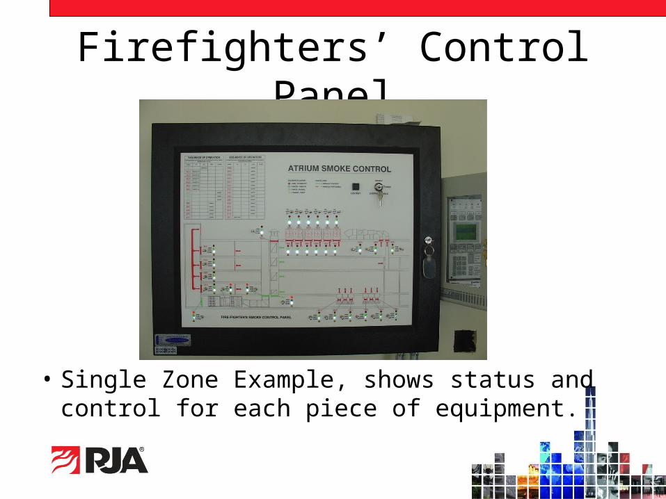
Firefighters’ Control Panel
• Multiple Zone Example, shows status and control on a zonal basis only.
Firefighters’ Control Panel
• Single Zone Example, shows status and control for each piece of equipment.
Firefighters’ Control Panel• System Status Indication:
– Pilot-lamp-type indicators required in 909.16.1 (LED’s more commonly used—more reliable, much longer life).
– Indication by each piece of equipment (fans, dampers).
– Alternately for complex systems, indication by single smoke zone of all zone associated equipment.

Firefighters’ Control Panel
• System Control (Override) Capability:– Manual switches by each equipment or by
whole zone.
– Don’t blow-up the duct!Stay aware of what you are doing if you throw any switch, anywhere, any time.

Commissioning

Special Inspection • Section 909.18.8 requires all smoke control
systems to be tested by a Special Inspector.– The Special Inspector shall have expertise in fire
protection engineering, mechanical engineering and/or certification as air balancers.
• Special Inspection is to occur:– During erection of ductwork and prior to concealment
for the purposes of leakage testing and recording of device location.
– Prior to occupancy and after sufficient completion for the purposes of pressure-difference testing, flow measurements, and detection and control verification.

Be Calm in the Chaos

Special Inspection• Team approach utilizing combination
of:
– Fire Protection/Mechanical Engineers.– Air Balance Personnel.– Fire Alarm/Controls Companies.
• More common during annual retesting.

Special Inspection
• Expertise in multiple fields required.
• Team approach often used.
• Lead Agency with subcontractors, subconsultants to fill out areas of expertise.– Observation of Builder’s Subcontractors.

Special Inspectors• Responsible to certify that the system has been
installed in accordance with the approved design documents, which are assumed to comply with the Code.
• The Special Inspector is not the Designer. Do not redesign the system. Where questions arise in the design, they must be referred to the Designer.
• Don’t try to break the system, test to the designer’s sequence of operation. Does the system work as designed?

Plan for Testing• Agree on performance goals.
– Contained in approved Rational Analysis.– If not, develop a test plan before testing begins.
• Confirm agreement with:– Design Engineer/Architect– Building and Fire Inspection Authorities– General Contractor– All Subcontractors

Plan for Testing
• Schedule test time, including time of day, days of the week.
• Keep the AHJ informed.
• Keep the Client informed.
• Keep the Contractor informed.

Inspection Sequence• Detailed device inspections.
• Subsystem operation tests.
• Full system functional tests.
• Air flow/pressure differential verification.
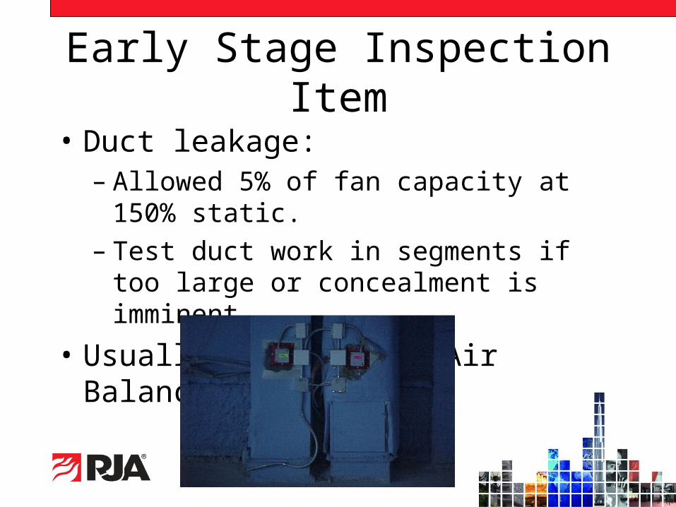
Early Stage Inspection Item
• Duct leakage:– Allowed 5% of fan capacity at 150% static.– Test duct work in segments if too large or
concealment is imminent.
• Usually done by the Air Balance firm.

Check Devices (Elements)• Fans – tag number, capacity, power,
speed, rotation, service rating, VFD settings, HOA bypass.

Check Devices (Elements)• Fire & smoke dampers - operation,
speed, installation, type, location, power.
• Doors - label, operation, location.
• Smoke barriers - leakage, integrity.

Check Full System Operation
• Sequence of events.
• Control Priorities—Automatic and Manual Overrides.
• Operability of other system components in alarm conditions.
• Emergency power.

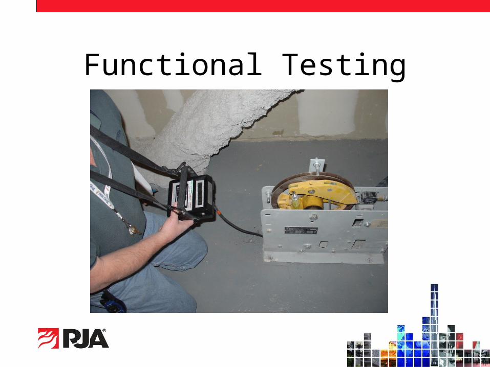
Functional Testing
• Pressure differential/exhaust air flow measurements - includes fan data.
Functional Testing

Pressure Tests
• Pressure gauges:–Lack the accuracy required to measure
system performance.
• Inclined manometer:–Specified in IBC, not very accurate.

Pressure Tests• Transducers:
–Equipment is calibrated to a known source.–Commonly used by air balance personnel.

Door Opening Forces• Verify door opening forces on all
or representative sample of doors at zone boundaries, including stair doors, to confirm opening force does not exceed the allowed door opening force. Will likely require adjustments to closers in some cases.
• Test apparatus can be easily obtained but can also be easily lost, so buy many.
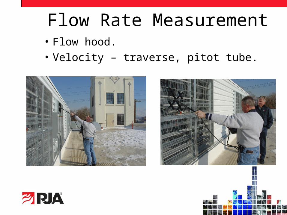
Flow Rate Measurement• Flow hood.
• Velocity – traverse, pitot tube.
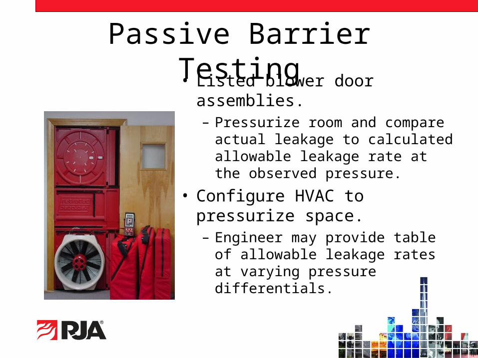
Passive Barrier Testing• Listed blower door
assemblies.– Pressurize room and compare
actual leakage to calculated allowable leakage rate at the observed pressure.
• Configure HVAC to pressurize space.– Engineer may provide table of
allowable leakage rates at varying pressure differentials.

Passive Barrier Testing• In general, if the room is ready to
test it should pass and that most rooms have actual leakage less than allowable by up to 50 percent.
• When testing representative sample of rooms, choose rooms for both sides of building.
• Equipment is usually calibrated with reference charts to be tested at 0.05-inch water column.
• When room is too large, multiple fans or door blowers can be used.

Test Methods - Reflect Design
• Systems are designed to manage where smoke goes.
• Systems are not designed to provide tenable conditions in the area of fire origin.
• Smoke tests, if used, should demonstrate air flow direction of the system considering the buoyant nature of smoke.

Other Test Methods
• Chemical smoke, tracer gas and real fire tests.– Limited value in evaluating certain system
performance.– Validity as methods of testing a smoke-control
system is questionable.– Detailed discussion in NFPA 92A, Section
A.5.3.3.6 and NFPA 92B, Section 5.3.6.2.
• Some jurisdictions will still require it.

Chemical Smoke Products

“Cold” Smoke Test

Documentation
• Complete test records are essential.
• Provide a copy of all test documentation to the Special Inspector:– Copy of deficiency lists provided to
General Contractor– Copy of interim and final air balance
reports.– Complete fan start-up information.

Documentation – Daily Report
The daily report provides specific information on the areas and system components tested, whether there were any deficiencies noted and resolved or left outstanding.

Documentation – NCRThe Non-Conformance Report identifies outstanding issues or deficiencies noted during the course of testing and also provides a means to officially notify the Contractor. Deficiencies should be specifically identified.

Documentation - Fans

Documentation – Passive Barriers

Additional Inspection Guidance
• National Environmental Balancing Bureau (NEBB).
• Associated Air Balance Council (AABC).• American Society of Heating, Refrigerating
and Air Conditioning Engineers (ASHRAE).• Society of Fire Protection Engineers (SFPE)• Sheet Metal and Air Conditioning Contractors
National Association (SMACNA).

Thank You For Your Time!
Questions?
rjainc.com (925) 938-3550


