SMISSLINE TP-Touch proof system Power and...
134
— SMISSLINE Technical catalogue SMISSLINE TP-Touch proof system Power and safety
Transcript of SMISSLINE TP-Touch proof system Power and...
— SMISSLINE
Technical catalogueSMISSLINE TP-Touch proof systemPower and safety

2 TECH N I C A L C ATA LO G U E SM ISSL I N E TP -TO U CH PR O O F S Y S TEM P OW ER A N D S A FE T Y
Small cause, large effect: as the world’s first pluggable socket system, SMISSLINE TP ensures that load-free devices and components can be snapped on and off under voltage without the need for additional personal protective equipment to guard against electrical hazards. That opens up completely new prospects for you when it comes to installation, operation and flexibility.
New Power Bar System 250 A The new 250 A system is now available in the shape of the SMISSLINE TP. The busbars have a rated amperage of 250 A and therefore allow a end feed of 250 A. This extends the spectrum of potential applications.
—Power behind barsThe world’s safest socket system

SM ISSL I N E TP -TO U CH PR O O F S Y S TEM P OW ER A N D S A FE T Y 3
Even safer: Protection against electrical hazards We have upgraded our unique SMISSLINE TP socket system even further through the addition of a pioneering innovation. With the new SMISSLINE TP system, components can now be plugged in or unplugged load-free without any risk from electrical current running through the body.The SMISSLINE TP pluggable socket system is completely finger-safe (IP20B) – when devices are plugged in and unplugged, the system is always touch-proof. This means that SMISSLINE TP pre-vents any danger to personnel from switching arcs or accidental arcing.
Even more flexible: make additions and changes during on going operationPluggable devices can be added and changed quickly, safely and simply during ongoing opera-tion. And this can be done without any need for personal protective equipment.This means that you benefit from more flexibility, savings on installation and maintenance – and improved safety. SMISSLINE TP provides greater availability and operating safety than conven-tional systems.
—Efficiency you can touchPlug in components during ongoing operation
4 TECH N I C A L C ATA LO G U E SM ISSL I N E TP -TO U CH PR O O F S Y S TEM P OW ER A N D S A FE T Y
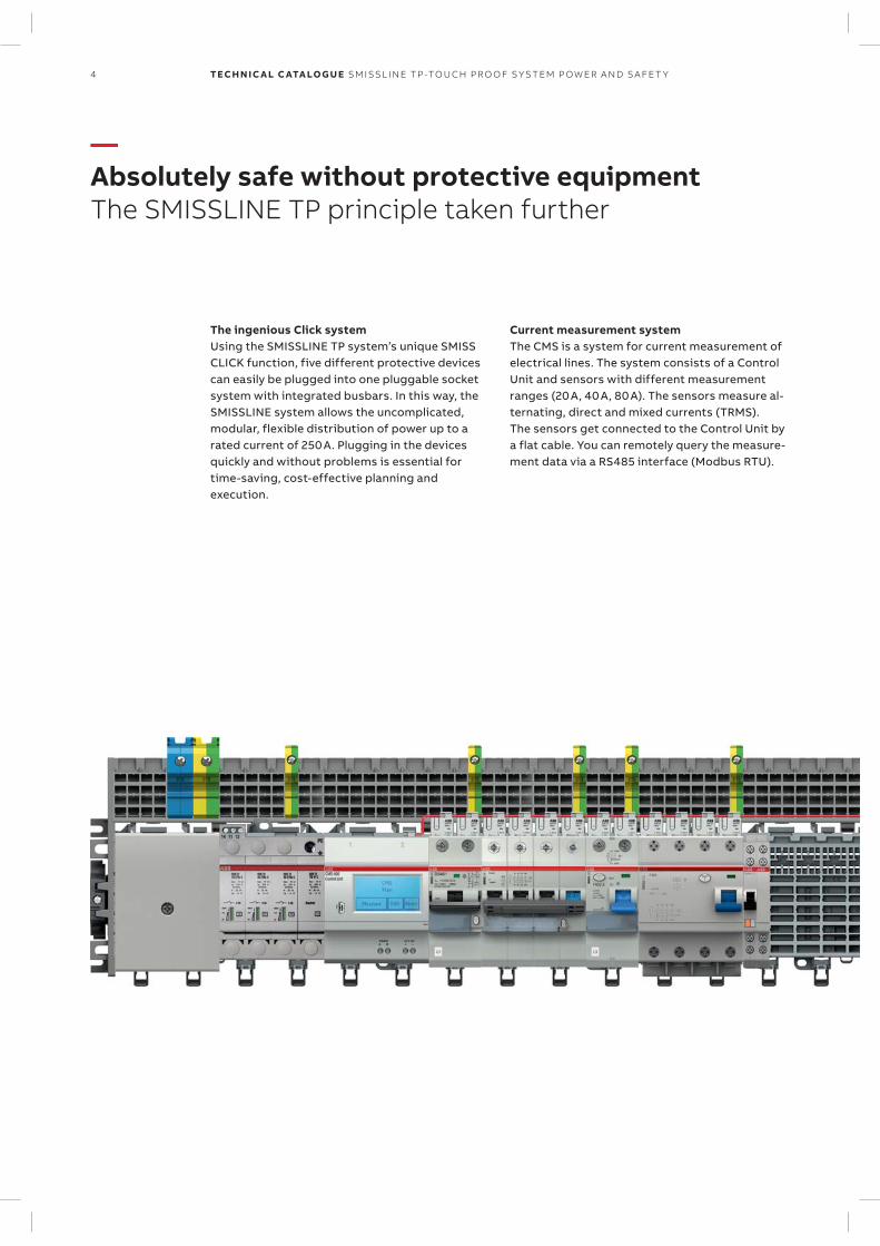
The ingenious Click systemUsing the SMISSLINE TP system’s unique SMISS CLICK function, five different protective devices can easily be plugged into one pluggable socket system with integrated busbars. In this way, the SMISSLINE system allows the uncomplicated, modular, flexible distribution of power up to a rated current of 250 A. Plugging in the devices quickly and without problems is essential for time-saving, cost-effective planning and execution.
Current measurement systemThe CMS is a system for current measurement of electrical lines. The system consists of a Control Unit and sensors with different measurement ranges (20 A, 40 A, 80 A). The sensors measure al-ternating, direct and mixed currents (TRMS). The sensors get connected to the Control Unit by a flat cable. You can remotely query the measure-ment data via a RS485 interface (Modbus RTU).
—Absolutely safe without protective equipmentThe SMISSLINE TP principle taken further
SM ISSL I N E TP -TO U CH PR O O F S Y S TEM P OW ER A N D S A FE T Y 5
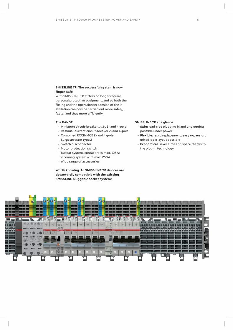
SMISSLINE TP: The successful system is now finger-safeWith SMISSLINE TP, fitters no longer require personal pro tective equipment, and so both the fitting and the operation/expansion of the in-stallation can now be carried out more safely, faster and thus more efficiently.
The RANGE - Miniature circuit-breaker 1-, 2-, 3- and 4-pole - Residual-current circuit-breaker 2- and 4-pole - Combined RCCB-MCB 2- and 4-pole - Surge arrester type 2 - Switch disconnector - Motor protection switch - Busbar system, contact rails max. 125 A;
incoming system with max. 250 A - Wide range of accessories
Worth knowing: All SMISSLINE TP devices are downwardly compatible with the existing SMISSLINE pluggable socket system!
SMISSLINE TP at a glance - Safe: load-free plugging in and unplugging
possible under power - Flexible: rapid replacement, easy expansion,
mixed-pole layout possible - Economical: saves time and space thanks to
the plug-in technology
6 TECH N I C A L C ATA LO G U E SM ISSL I N E TP -TO U CH PR O O F S Y S TEM P OW ER A N D S A FE T Y
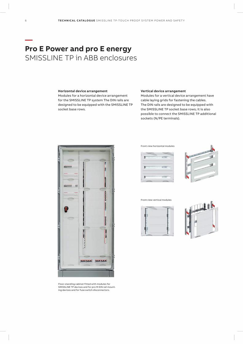
Horizontal device arrangementModules for a horizontal device arrangement for the SMISSLINE TP system The DIN rails are designed to be equipped with the SMISSLINE TP socket base rows.
Vertical device arrangementModules for a vertical device arrangement have cable laying grids for fastening the cables. The DIN rails are designed to be equipped with the SMISSLINE TP socket base rows; it is also possible to connect the SMISSLINE TP additional sockets (N/PE terminals).
—Pro E Power and pro E energySMISSLINE TP in ABB enclosures
Front view horizontal modules
Floor-standing cabinet fitted with modules for SMISSLINE TP devices and for pro M DIN rail mount-ing devices and for fuse switch disconnectors.
Front view vertical modules
SM ISSL I N E TP -TO U CH PR O O F S Y S TEM P OW ER A N D S A FE T Y 7
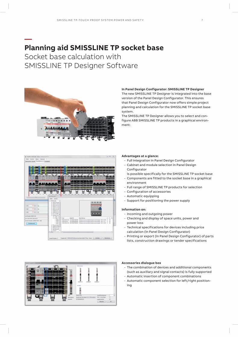
In Panel Design Configurator: SMISSLINE TP DesignerThe new SMISSLINE TP Designer is integrated into the base version of the Panel Design Configurator. This ensures that Panel Design Configurator now offers simple project planning and calculation for the SMISSLINE TP socket base system. The SMISSLINE TP Designer allows you to select and con-figure ABB SMISSLINE TP products in a graphical environ-ment:
Advantages at a glance: - Full integration in Panel Design Configurator - Cabinet and module selection in Panel Design
Configurator is possible specifically for the SMISSLINE TP socket base
- Components are fitted to the socket base in a graphical environment
- Full range of SMISSLINE TP products for selection - Configuration of accessories - Automatic equipping - Support for positioning the power supply
Information on:
- Incoming and outgoing power - Checking and display of space units, power and
power loss - Technical specifications for devices including price
calculation (in Panel Design Configurator) - Printing or export (in Panel Design Configurator) of parts
lists, construction drawings or tender specifications
Accessories dialogue box - The combination of devices and additional components
(such as auxiliary and signal contacts) is fully supported - Automatic insertion of component combinations - Automatic component selection for left/right position-
ing
—Planning aid SMISSLINE TP socket baseSocket base calculation with SMISSLINE TP Designer Software

8 TECH N I C A L C ATA LO G U E SM ISSL I N E TP -TO U CH PR O O F S Y S TEM P OW ER A N D S A FE T Y
—Remote Power Panel – Data CenterApplication Note
Backup protectionBased on backup and selectivity requirements a Molded Case Circuit Breaker (XT4) is used to protect the Sub-Distribution. The rating can go up to 250 A per MCCB if parallel incoming is used. The Backup protection complies with IEC/EN 60898-1 and IEC/EN 60947-2 and allows industrial use. With the integrated COM-Module all voltages, currents, power factors and status data is available through a Modbus RTU interface.
Circuit Monitoring System Control Unit – CMS-700RPP’s heart is the Control Unit CMS-700 which aggregates the current readings from the CMS and the Power Quality Values to create consumption data and generate alarms in case of system errors. In addition to the optional front door touch display CP651-WEB, a generic Modbus TCP and SNMP interface is sup-ported. Typically this protocols are used to interface the data center infrastruc-ture management system – DCIM.
Circuit Monitoring System – open core and solid core sensorsABB’s CMS is the most compact, neat and hassle-free branch circuit monitoring system available on the market. The sensors are mounted directly on the SMISSLINE Miniature Circuit Breakers and there is no need of conventional expensive and cumbersome cabling thanks to internal Modbus instead of typical Current Transformer star wiring. The new range of open core sensors helps to add branch monitoring into existing installations without the need to power -off they system.
Touch proof system - SMISSLINE TPThe world’s first pluggable and touch proof socket system, SMISSLINE TP ensures that load-free devices and components can be safely snapped on and off under voltage without shutting down one single server. In addition maintenance can be done by instructed personnel without electrician’s qualification. Moreover you can save 20 % space for the typical A/B distribution in a data center. Compared to a conventional build up time of 15 hours of an RPP like this – SMISSLINE needs only 8h which allows another 45 % of time saving.
Power Quality AnalyzerThe Power Quality Analyzer has dual function. First, it provides the voltage and power factor reference value to the PLC for calculating the effective power and energy values for the branch circuit. It allows the class III system reports accord-ing to DIN EN 61000-2-4 secondly, it provides the following data for the complete RPP:
- Active, reactive and apparent power - Residual current monitoring - Voltage quality (DIN EN 50160) - Frequency and power factor - Total harmonic distortion
SM ISSL I N E TP -TO U CH PR O O F S Y S TEM P OW ER A N D S A FE T Y
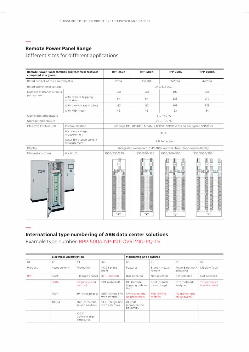
Remote Power Panel families and technical features compared at a glace:
RPP-250A RPP-500A RPP-750A RPP-1000A
Rated current of the assembly (Ina) 250A 2x250A 3x250A 4x250A
Rated operational voltage 240/415 VAC
Number of branch circuits per system
128 128 192 256
with remote tripping indication
84 84 128 170
with overvoltage module 112 112 168 222
with MID meter 42 42 63 84
Operating temperature -5 ... +40 °C
Storage temperature -25 … +70 °C
CMS-700 Control Unit Communication Modbus RTU (RS485); Modbus TCP/IP; SNMP v1/2 and encrypted SNMP v3
Accuracy voltage measurement
±1 %
Accuracy branch current measurement
±1 % full scale
Display Integrated webserver (CMS-700); optional front door device/display
Dimensions (mm) H x W x D 1950/550/350 1950/550/350 1950/800/350 1950/1050/350
Electrical Specification Monitoring and Features
X1 X2 X3 X4 X5 X6 X7 X8
Product Input current Protection MCCB place-ment
Features Branch measu-rement
Power& network analyzing
Display/Touch
RPP 250A P (single phase) INT (internal) Not selected Not selected Not selected Not selected
500A NP (phase and neutral)
EXT (external) RTI (remote tripping indica-tion)
BCM (branch monitoring)
NET (network analyzer)
TS (panel pc/ touchscreen)
750A 3P (three phase) SINT (single line with internal)
OVR (overvolta-ge protection)
MID (billing meters)
PQ (power qua-lity analyzer)
1000A 3NP (three pha-se and neutral)
SEXT (single line with external)
RTIOVR (combination RTI&OVR)
KXXX (tolerant trip-ping curve)
—International type numbering of ABB data center solutionsExample type number: RPP-500A-NP-INT-OVR-MID-PQ-TS
—Remote Power Panel RangeDifferent sizes for different applications
3 4 5 6 7 138 1210 1121 9
14
10 TECH N I C A L C ATA LO G U E SM ISSL I N E TP -TO U CH PR O O F S Y S TEM P OW ER A N D S A FE T Y
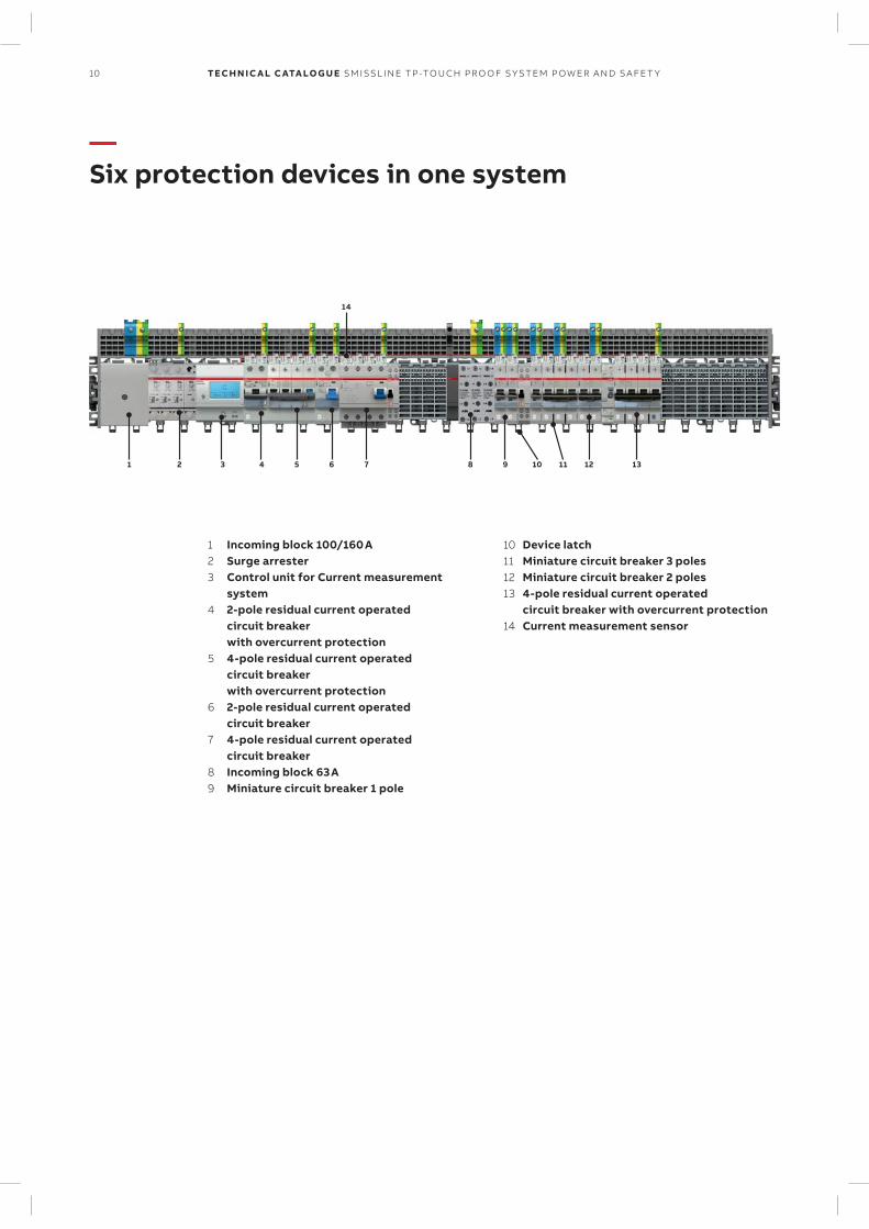
—Six protection devices in one system
1 Incoming block 100/160 A2 Surge arrester3 Control unit for Current measurement
system4 2-pole residual current operated
circuit breaker with overcurrent protection
5 4-pole residual current operated circuit breaker with overcurrent protection
6 2-pole residual current operated circuit breaker
7 4-pole residual current operated circuit breaker
8 Incoming block 63 A9 Miniature circuit breaker 1 pole
10 Device latch11 Miniature circuit breaker 3 poles12 Miniature circuit breaker 2 poles13 4-pole residual current operated
circuit breaker with overcurrent protection14 Current measurement sensor
11SM ISSL I N E TP -TO U CH PR O O F S Y S TEM P OW ER A N D S A FE T Y
— Table of conteantsSMISSLINE TP
012 – 027 Miniature circuit breaker S400
028 – 033 Residual current operated circuit breaker FS401
034 – 035 Residual current operated circuit breaker F402, F404
036 – 037 Surge arrester OVR, Switch disconnector
038 – 040 Combi module , Adapter for motor starter
041 – 044 Auxiliary switches and signal contacts, Shunt trip, Neutral disconnector
045 – 048 Motor operating device
049 – 050 CMS- Circuit Monitoring System
051 – 064 Busbar system 125 A
065 – 070 Power Bar System 250 A
2CC
C41
0018
Z00
01
1
2
3
4 2CC
C40
4023
Z00
01
1
2
3
4
5
6 2CC
C40
4024
Z00
012C
CC
4040
25Z
00011 3
2 4
5 7/N
6 8/N
1
2
1
3
N
N
12 TECH N I C A L C ATA LO G U E SM ISSL I N E TP -TO U CH PR O O F S Y S TEM P OW ER A N D S A FE T Y
—Miniature circuit breakerProperties
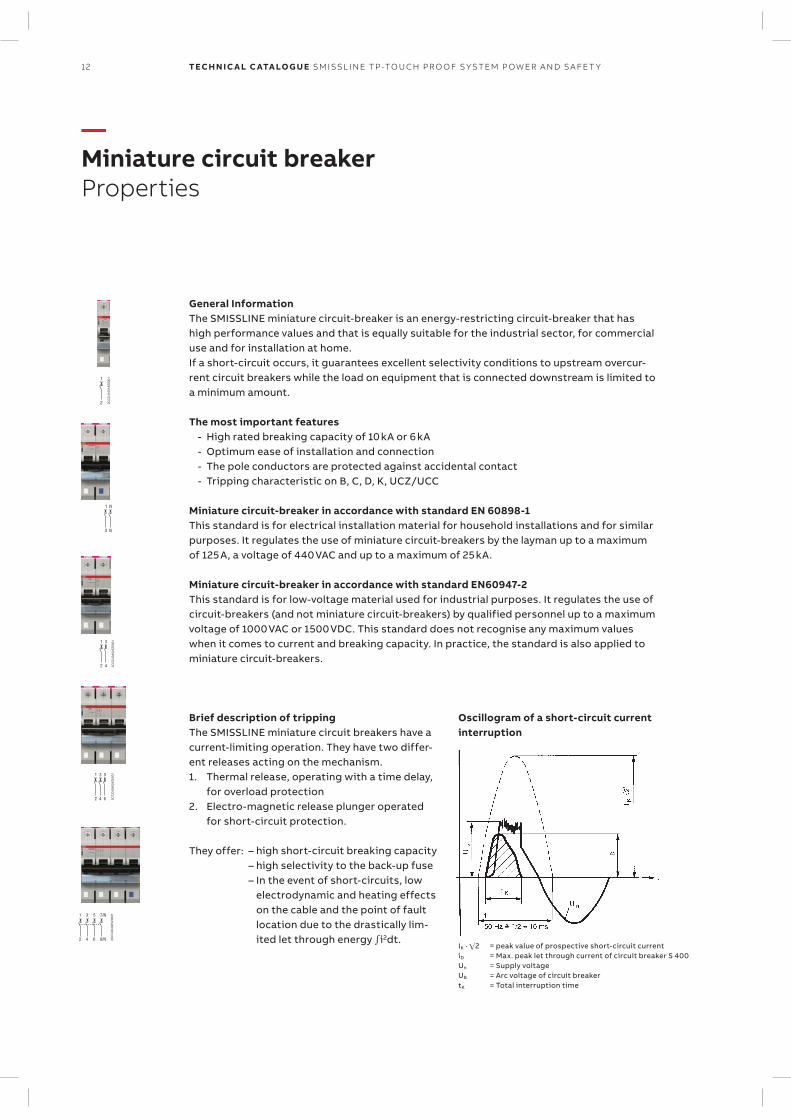
General InformationThe SMISSLINE miniature circuit-breaker is an energy-restricting circuit-breaker that has high performance values and that is equally suitable for the industrial sector, for commercial use and for installation at home. If a short-circuit occurs, it guarantees excellent selectivity conditions to upstream overcur-rent circuit breakers while the load on equipment that is connected downstream is limited to a minimum amount.
The most important features - High rated breaking capacity of 10 kA or 6 kA - Optimum ease of installation and connection - The pole conductors are protected against accidental contact - Tripping characteristic on B, C, D, K, UCZ/UCC
Miniature circuit-breaker in accordance with standard EN 60898-1This standard is for electrical installation material for household installations and for similar purposes. It regulates the use of miniature circuit-breakers by the layman up to a maximum of 125 A, a voltage of 440 VAC and up to a maximum of 25 kA.
Miniature circuit-breaker in accordance with standard EN60947-2This standard is for low-voltage material used for industrial purposes. It regulates the use of circuit-breakers (and not miniature circuit-breakers) by qualified personnel up to a maximum voltage of 1000 VAC or 1500 VDC. This standard does not recognise any maximum values when it comes to current and breaking capacity. In practice, the standard is also applied to miniature circuit-breakers.
Oscillogram of a short-circuit current interruption
Brief description of trippingThe SMISSLINE miniature circuit breakers have a current-limiting operation. They have two differ-ent releases acting on the mechanism.1. Thermal release, operating with a time delay,
for overload protection2. Electro-magnetic release plunger operated
for short-circuit protection.
They offer: – high short-circuit breaking capacity – high selectivity to the back-up fuse – In the event of short-circuits, low
electrodynamic and heating effects on the cable and the point of fault location due to the drastically lim-ited let through energy i2dt.
IK · 2 = peak value of prospective short-circuit currentiD = Max. peak let through current of circuit breaker S 400 Un = Supply voltageUB = Arc voltage of circuit breakertK = Total interruption time
13SM ISSL I N E TP -TO U CH PR O O F S Y S TEM P OW ER A N D S A FE T Y
—Miniature circuit breakerTechnical data S400E, S400M
—When installed correctly the requirements of EN/IEC 61439-2 are met.
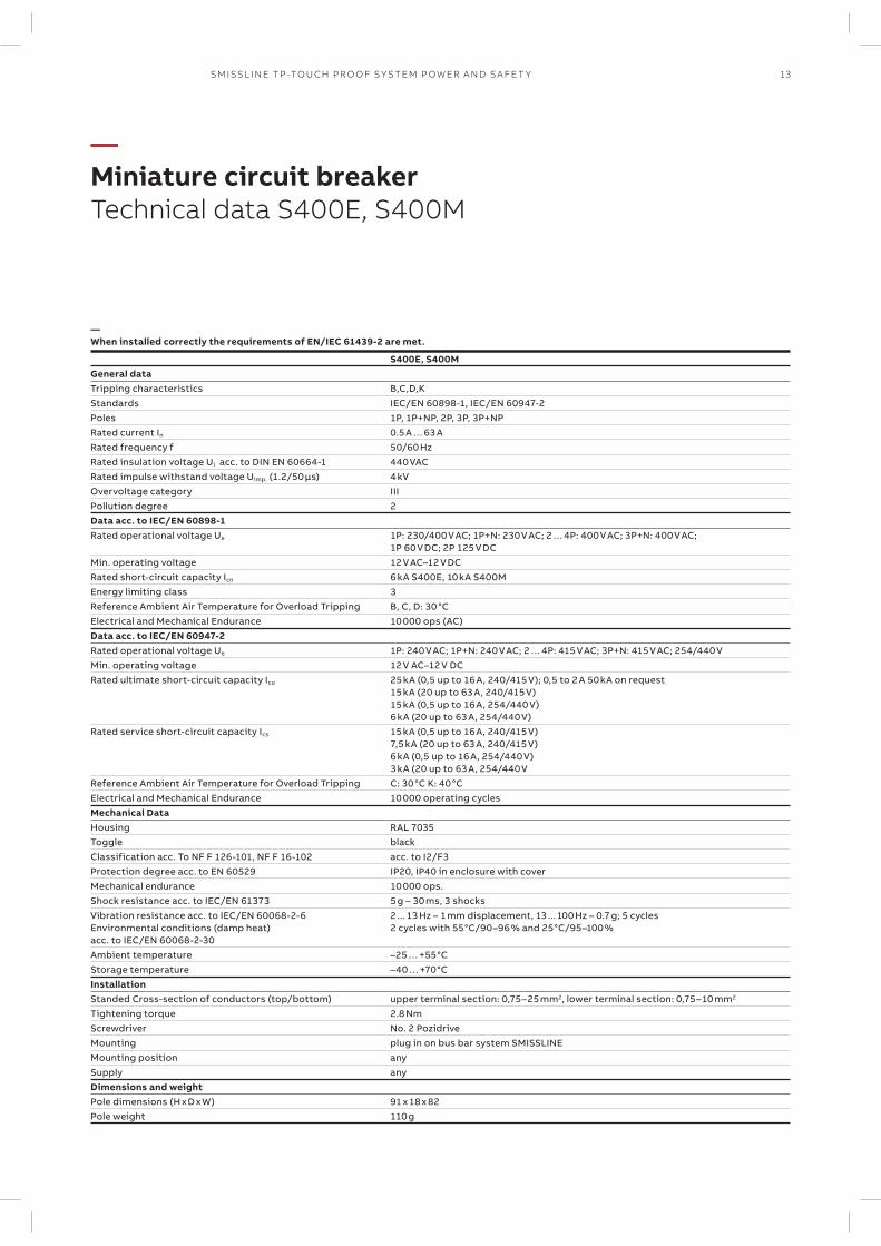
S400E, S400MGeneral dataTripping characteristics B,C,D,KStandards IEC/EN 60898-1, IEC/EN 60947-2Poles 1P, 1P+NP, 2P, 3P, 3P+NPRated current In 0.5 A … 63 ARated frequency f 50/60 HzRated insulation voltage Ui acc. to DIN EN 60664-1 440 VACRated impulse withstand voltage Uimp. (1.2/50 µs) 4 kVOvervoltage category IIIPollution degree 2Data acc. to IEC/EN 60898-1Rated operational voltage Ue 1P: 230/400 V AC; 1P+N: 230 V AC; 2 … 4P: 400 V AC; 3P+N: 400 V AC;
1P 60 V DC; 2P 125 V DCMin. operating voltage 12 V AC–12 V DCRated short-circuit capacity Icn 6 kA S400E, 10 kA S400MEnergy limiting class 3Reference Ambient Air Temperature for Overload Tripping B, C, D: 30 °CElectrical and Mechanical Endurance 10 000 ops (AC)Data acc. to IEC/EN 60947-2Rated operational voltage Ue 1P: 240 V AC; 1P+N: 240 V AC; 2 … 4P: 415 V AC; 3P+N: 415 V AC; 254/440 V Min. operating voltage 12 V AC–12 V DCRated ultimate short-circuit capacity Icu 25 kA (0,5 up to 16 A, 240/415 V); 0,5 to 2 A 50 kA on request
15 kA (20 up to 63 A, 240/415 V) 15 kA (0,5 up to 16 A, 254/440 V) 6 kA (20 up to 63 A, 254/440 V)
Rated service short-circuit capacity Ics 15 kA (0,5 up to 16 A, 240/415 V)7,5 kA (20 up to 63 A, 240/415 V) 6 kA (0,5 up to 16 A, 254/440 V) 3 kA (20 up to 63 A, 254/440 V
Reference Ambient Air Temperature for Overload Tripping C: 30 °C K: 40 °CElectrical and Mechanical Endurance 10 000 operating cyclesMechanical Data Housing RAL 7035Toggle blackClassification acc. To NF F 126-101, NF F 16-102 acc. to I2/F3Protection degree acc. to EN 60529 IP20, IP40 in enclosure with coverMechanical endurance 10 000 ops.Shock resistance acc. to IEC/EN 61373 5 g – 30 ms, 3 shocksVibration resistance acc. to IEC/EN 60068-2-6Environmental conditions (damp heat)acc. to IEC/EN 60068-2-30
2 ... 13 Hz – 1 mm displacement, 13 ... 100 Hz – 0.7 g; 5 cycles2 cycles with 55 °C/90–96 % and 25 °C/95–100 %
Ambient temperature –25 … +55 °CStorage temperature –40 … +70 °CInstallationStanded Cross-section of conductors (top/bottom) upper terminal section: 0,75–25 mm2, lower terminal section: 0,75–10 mm2
Tightening torque 2.8 NmScrewdriver No. 2 PozidriveMounting plug in on bus bar system SMISSLINEMounting position anySupply anyDimensions and weight Pole dimensions (H x D x W) 91 x 18 x 82Pole weight 110 g
14 TECH N I C A L C ATA LO G U E SM ISSL I N E TP -TO U CH PR O O F S Y S TEM P OW ER A N D S A FE T Y
—Miniature circuit breakerTechnical data S400UC
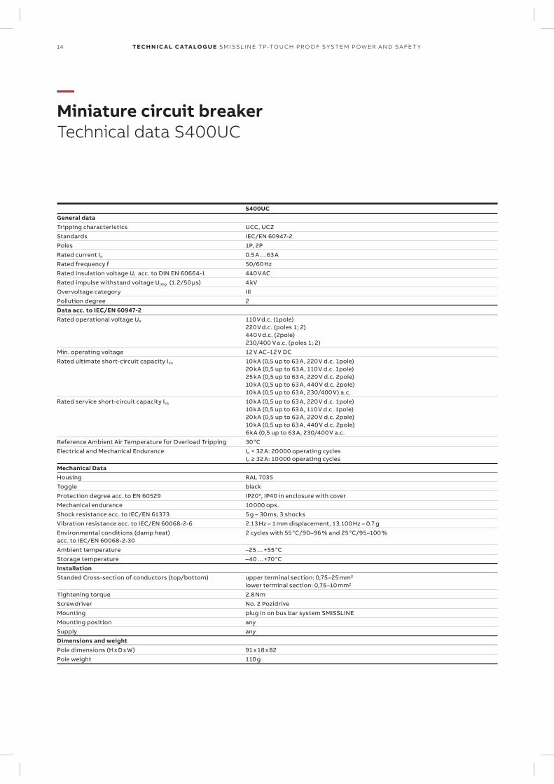
S400UCGeneral dataTripping characteristics UCC, UCZStandards IEC/EN 60947-2Poles 1P, 2PRated current In 0.5 A … 63 ARated frequency f 50/60 HzRated insulation voltage Ui acc. to DIN EN 60664-1 440 V ACRated impulse withstand voltage Uimp. (1.2/50 µs) 4 kVOvervoltage category IIIPollution degree 2Data acc. to IEC/EN 60947-2Rated operational voltage Ue 110 V d.c. (1pole)
220 V d.c. (poles 1; 2)440 V d.c. (2pole)230/400 V a.c. (poles 1; 2)
Min. operating voltage 12 V AC–12 V DCRated ultimate short-circuit capacity Icu 10 kA (0,5 up to 63 A, 220 V d.c. 1pole)
20 kA (0,5 up to 63 A, 110 V d.c. 1pole) 25 kA (0,5 up to 63 A, 220 V d.c. 2pole)10 kA (0,5 up to 63 A, 440 V d.c. 2pole) 10 kA (0,5 up to 63 A, 230/400 V) a.c.
Rated service short-circuit capacity Ics 10 kA (0,5 up to 63 A, 220 V d.c. 1pole) 10 kA (0,5 up to 63 A, 110 V d.c. 1pole) 20 kA (0,5 up to 63 A, 220 V d.c. 2pole) 10 kA (0,5 up to 63 A, 440 V d.c. 2pole) 6 kA (0,5 up to 63 A, 230/400 V a.c.
Reference Ambient Air Temperature for Overload Tripping 30 °CElectrical and Mechanical Endurance In < 32 A: 20 000 operating cycles
In ≥ 32 A: 10 000 operating cyclesMechanical Data Housing RAL 7035Toggle blackProtection degree acc. to EN 60529 IP20*, IP40 in enclosure with coverMechanical endurance 10 000 ops.Shock resistance acc. to IEC/EN 61373 5 g – 30 ms, 3 shocksVibration resistance acc. to IEC/EN 60068-2-6 2.13 Hz – 1 mm displacement, 13.100 Hz – 0.7 gEnvironmental conditions (damp heat)acc. to IEC/EN 60068-2-30
2 cycles with 55 °C/90–96 % and 25 °C/95–100 %
Ambient temperature –25 … +55 °CStorage temperature –40 … +70 °CInstallationStanded Cross-section of conductors (top/bottom) upper terminal section: 0,75–25 mm2
lower terminal section: 0,75–10 mm2
Tightening torque 2.8 NmScrewdriver No. 2 PozidriveMounting plug in on bus bar system SMISSLINEMounting position anySupply anyDimensions and weight Pole dimensions (H x D x W) 91 x 18 x 82Pole weight 110 g
1
2
1 3
2 4
1 3
2 4
5
6
15SM ISSL I N E TP -TO U CH PR O O F S Y S TEM P OW ER A N D S A FE T Y
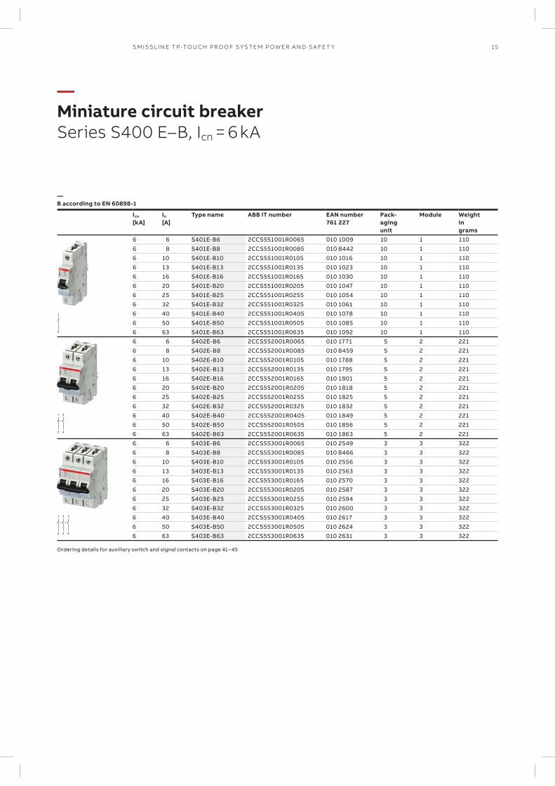
—Miniature circuit breakerSeries S400 E–B, Icn = 6 kA
—B according to EN 60898-1
Icn
[kA]In
[A]Type name ABB IT number EAN number
761 227Pack-agingunit
Module Weightingrams
6 6 S401E-B6 2CCS551001R0065 010 1009 10 1 1106 8 S401E-B8 2CCS551001R0085 010 8442 10 1 1106 10 S401E-B10 2CCS551001R0105 010 1016 10 1 1106 13 S401E-B13 2CCS551001R0135 010 1023 10 1 1106 16 S401E-B16 2CCS551001R0165 010 1030 10 1 1106 20 S401E-B20 2CCS551001R0205 010 1047 10 1 1106 25 S401E-B25 2CCS551001R0255 010 1054 10 1 1106 32 S401E-B32 2CCS551001R0325 010 1061 10 1 1106 40 S401E-B40 2CCS551001R0405 010 1078 10 1 1106 50 S401E-B50 2CCS551001R0505 010 1085 10 1 1106 63 S401E-B63 2CCS551001R0635 010 1092 10 1 1106 6 S402E-B6 2CCS552001R0065 010 1771 5 2 2216 8 S402E-B8 2CCS552001R0085 010 8459 5 2 2216 10 S402E-B10 2CCS552001R0105 010 1788 5 2 2216 13 S402E-B13 2CCS552001R0135 010 1795 5 2 2216 16 S402E-B16 2CCS552001R0165 010 1801 5 2 2216 20 S402E-B20 2CCS552001R0205 010 1818 5 2 2216 25 S402E-B25 2CCS552001R0255 010 1825 5 2 2216 32 S402E-B32 2CCS552001R0325 010 1832 5 2 2216 40 S402E-B40 2CCS552001R0405 010 1849 5 2 2216 50 S402E-B50 2CCS552001R0505 010 1856 5 2 2216 63 S402E-B63 2CCS552001R0635 010 1863 5 2 2216 6 S403E-B6 2CCS553001R0065 010 2549 3 3 3226 8 S403E-B8 2CCS553001R0085 010 8466 3 3 3226 10 S403E-B10 2CCS553001R0105 010 2556 3 3 3226 13 S403E-B13 2CCS553001R0135 010 2563 3 3 3226 16 S403E-B16 2CCS553001R0165 010 2570 3 3 3226 20 S403E-B20 2CCS553001R0205 010 2587 3 3 3226 25 S403E-B25 2CCS553001R0255 010 2594 3 3 3226 32 S403E-B32 2CCS553001R0325 010 2600 3 3 3226 40 S403E-B40 2CCS553001R0405 010 2617 3 3 3226 50 S403E-B50 2CCS553001R0505 010 2624 3 3 3226 63 S403E-B63 2CCS553001R0635 010 2631 3 3 322
Ordering details for auxiliary switch and signal contacts on page 41 – 45
1
2
1 3
2 4
1 3
2 4
5
6
16 TECH N I C A L C ATA LO G U E SM ISSL I N E TP -TO U CH PR O O F S Y S TEM P OW ER A N D S A FE T Y
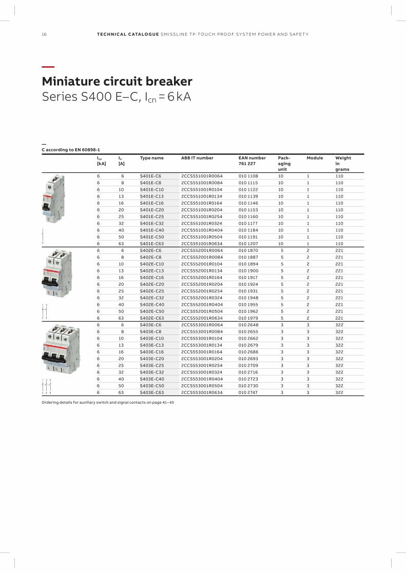
—Miniature circuit breakerSeries S400 E–C, Icn = 6 kA
—C according to EN 60898-1
Icn
[kA]In
[A]Type name ABB IT number EAN number
761 227Pack-agingunit
Module Weightingrams
6 6 S401E-C6 2CCS551001R0064 010 1108 10 1 1106 8 S401E-C8 2CCS551001R0084 010 1115 10 1 1106 10 S401E-C10 2CCS551001R0104 010 1122 10 1 1106 13 S401E-C13 2CCS551001R0134 010 1139 10 1 1106 16 S401E-C16 2CCS551001R0164 010 1146 10 1 1106 20 S401E-C20 2CCS551001R0204 010 1153 10 1 1106 25 S401E-C25 2CCS551001R0254 010 1160 10 1 1106 32 S401E-C32 2CCS551001R0324 010 1177 10 1 1106 40 S401E-C40 2CCS551001R0404 010 1184 10 1 1106 50 S401E-C50 2CCS551001R0504 010 1191 10 1 1106 63 S401E-C63 2CCS551001R0634 010 1207 10 1 1106 6 S402E-C6 2CCS552001R0064 010 1870 5 2 2216 8 S402E-C8 2CCS552001R0084 010 1887 5 2 2216 10 S402E-C10 2CCS552001R0104 010 1894 5 2 2216 13 S402E-C13 2CCS552001R0134 010 1900 5 2 2216 16 S402E-C16 2CCS552001R0164 010 1917 5 2 2216 20 S402E-C20 2CCS552001R0204 010 1924 5 2 2216 25 S402E-C25 2CCS552001R0254 010 1931 5 2 2216 32 S402E-C32 2CCS552001R0324 010 1948 5 2 2216 40 S402E-C40 2CCS552001R0404 010 1955 5 2 2216 50 S402E-C50 2CCS552001R0504 010 1962 5 2 2216 63 S402E-C63 2CCS552001R0634 010 1979 5 2 2216 6 S403E-C6 2CCS553001R0064 010 2648 3 3 3226 8 S403E-C8 2CCS553001R0084 010 2655 3 3 3226 10 S403E-C10 2CCS553001R0104 010 2662 3 3 3226 13 S403E-C13 2CCS553001R0134 010 2679 3 3 3226 16 S403E-C16 2CCS553001R0164 010 2686 3 3 3226 20 S403E-C20 2CCS553001R0204 010 2693 3 3 3226 25 S403E-C25 2CCS553001R0254 010 2709 3 3 3226 32 S403E-C32 2CCS553001R0324 010 2716 3 3 3226 40 S403E-C40 2CCS553001R0404 010 2723 3 3 3226 50 S403E-C50 2CCS553001R0504 010 2730 3 3 3226 63 S403E-C63 2CCS553001R0634 010 2747 3 3 322
Ordering details for auxiliary switch and signal contacts on page 41 – 45
1 3/N
2 4/N
17SM ISSL I N E TP -TO U CH PR O O F S Y S TEM P OW ER A N D S A FE T Y
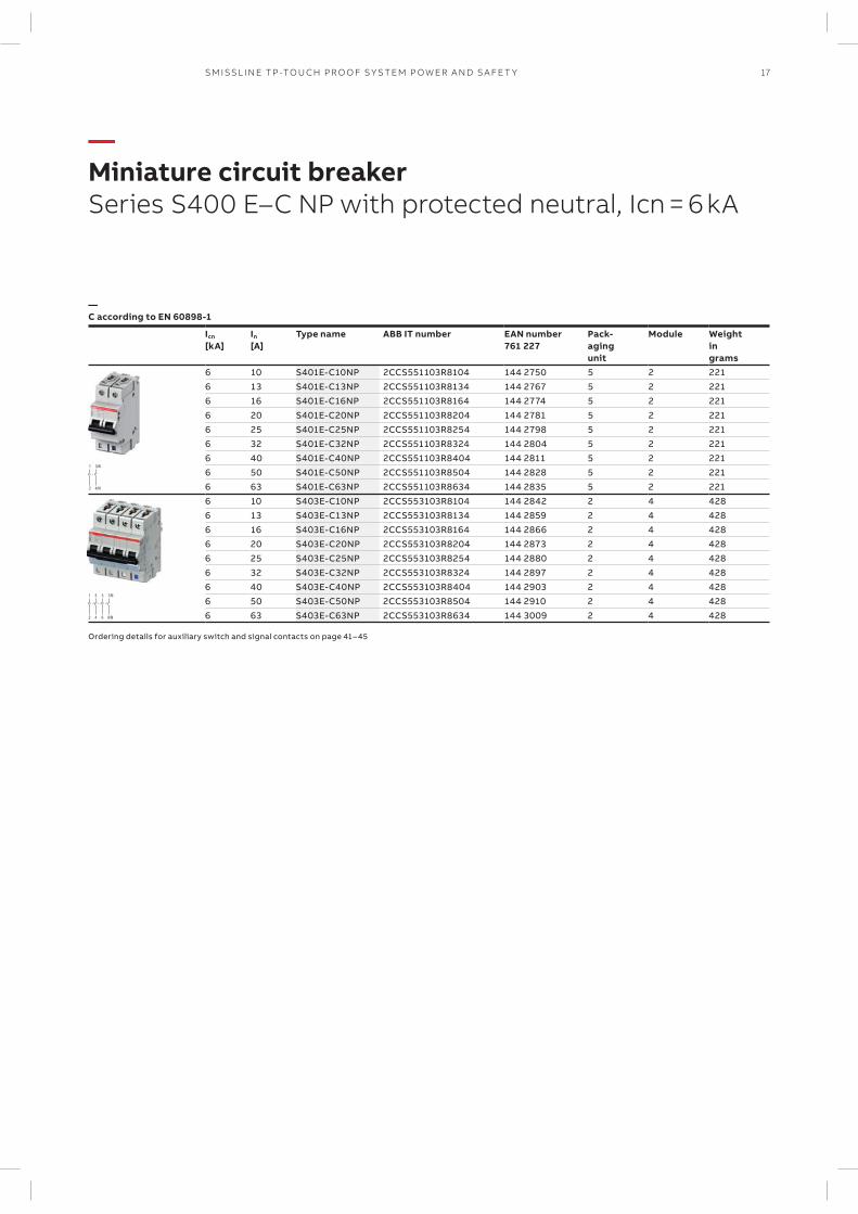
—Miniature circuit breakerSeries S400 E–C NP with protected neutral, Icn = 6 kA
—C according to EN 60898-1
Icn
[kA]In
[A]Type name ABB IT number EAN number
761 227Pack-agingunit
Module Weightingrams
6 10 S401E-C10NP 2CCS551103R8104 144 2750 5 2 2216 13 S401E-C13NP 2CCS551103R8134 144 2767 5 2 2216 16 S401E-C16NP 2CCS551103R8164 144 2774 5 2 2216 20 S401E-C20NP 2CCS551103R8204 144 2781 5 2 2216 25 S401E-C25NP 2CCS551103R8254 144 2798 5 2 2216 32 S401E-C32NP 2CCS551103R8324 144 2804 5 2 2216 40 S401E-C40NP 2CCS551103R8404 144 2811 5 2 2216 50 S401E-C50NP 2CCS551103R8504 144 2828 5 2 2216 63 S401E-C63NP 2CCS551103R8634 144 2835 5 2 2216 10 S403E-C10NP 2CCS553103R8104 144 2842 2 4 4286 13 S403E-C13NP 2CCS553103R8134 144 2859 2 4 4286 16 S403E-C16NP 2CCS553103R8164 144 2866 2 4 4286 20 S403E-C20NP 2CCS553103R8204 144 2873 2 4 4286 25 S403E-C25NP 2CCS553103R8254 144 2880 2 4 4286 32 S403E-C32NP 2CCS553103R8324 144 2897 2 4 4286 40 S403E-C40NP 2CCS553103R8404 144 2903 2 4 4286 50 S403E-C50NP 2CCS553103R8504 144 2910 2 4 4286 63 S403E-C63NP 2CCS553103R8634 144 3009 2 4 428
Ordering details for auxiliary switch and signal contacts on page 41 – 45
1 3
2 4
5
6
1
2
18 TECH N I C A L C ATA LO G U E SM ISSL I N E TP -TO U CH PR O O F S Y S TEM P OW ER A N D S A FE T Y
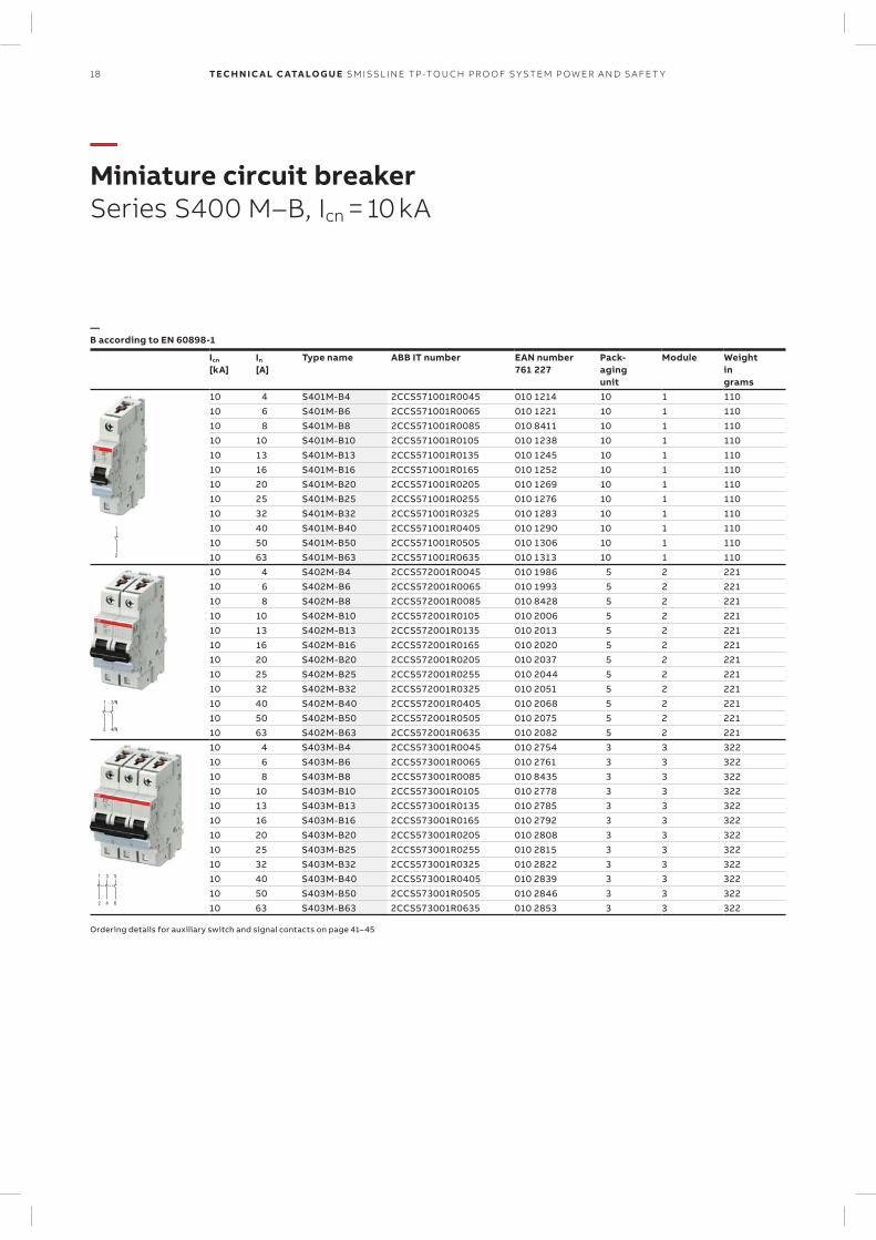
—Miniature circuit breakerSeries S400 M–B, Icn = 10 kA
—B according to EN 60898-1
Icn
[kA]In
[A]Type name ABB IT number EAN number
761 227Pack-agingunit
Module Weightingrams
10 4 S401M-B4 2CCS571001R0045 010 1214 10 1 11010 6 S401M-B6 2CCS571001R0065 010 1221 10 1 11010 8 S401M-B8 2CCS571001R0085 010 8411 10 1 11010 10 S401M-B10 2CCS571001R0105 010 1238 10 1 11010 13 S401M-B13 2CCS571001R0135 010 1245 10 1 11010 16 S401M-B16 2CCS571001R0165 010 1252 10 1 11010 20 S401M-B20 2CCS571001R0205 010 1269 10 1 11010 25 S401M-B25 2CCS571001R0255 010 1276 10 1 11010 32 S401M-B32 2CCS571001R0325 010 1283 10 1 11010 40 S401M-B40 2CCS571001R0405 010 1290 10 1 11010 50 S401M-B50 2CCS571001R0505 010 1306 10 1 11010 63 S401M-B63 2CCS571001R0635 010 1313 10 1 11010 4 S402M-B4 2CCS572001R0045 010 1986 5 2 22110 6 S402M-B6 2CCS572001R0065 010 1993 5 2 22110 8 S402M-B8 2CCS572001R0085 010 8428 5 2 22110 10 S402M-B10 2CCS572001R0105 010 2006 5 2 22110 13 S402M-B13 2CCS572001R0135 010 2013 5 2 22110 16 S402M-B16 2CCS572001R0165 010 2020 5 2 22110 20 S402M-B20 2CCS572001R0205 010 2037 5 2 22110 25 S402M-B25 2CCS572001R0255 010 2044 5 2 22110 32 S402M-B32 2CCS572001R0325 010 2051 5 2 22110 40 S402M-B40 2CCS572001R0405 010 2068 5 2 22110 50 S402M-B50 2CCS572001R0505 010 2075 5 2 22110 63 S402M-B63 2CCS572001R0635 010 2082 5 2 22110 4 S403M-B4 2CCS573001R0045 010 2754 3 3 32210 6 S403M-B6 2CCS573001R0065 010 2761 3 3 32210 8 S403M-B8 2CCS573001R0085 010 8435 3 3 32210 10 S403M-B10 2CCS573001R0105 010 2778 3 3 32210 13 S403M-B13 2CCS573001R0135 010 2785 3 3 32210 16 S403M-B16 2CCS573001R0165 010 2792 3 3 32210 20 S403M-B20 2CCS573001R0205 010 2808 3 3 32210 25 S403M-B25 2CCS573001R0255 010 2815 3 3 32210 32 S403M-B32 2CCS573001R0325 010 2822 3 3 32210 40 S403M-B40 2CCS573001R0405 010 2839 3 3 32210 50 S403M-B50 2CCS573001R0505 010 2846 3 3 32210 63 S403M-B63 2CCS573001R0635 010 2853 3 3 322
Ordering details for auxiliary switch and signal contacts on page 41– 45
1 3
2 4
5
6
1
2
19SM ISSL I N E TP -TO U CH PR O O F S Y S TEM P OW ER A N D S A FE T Y
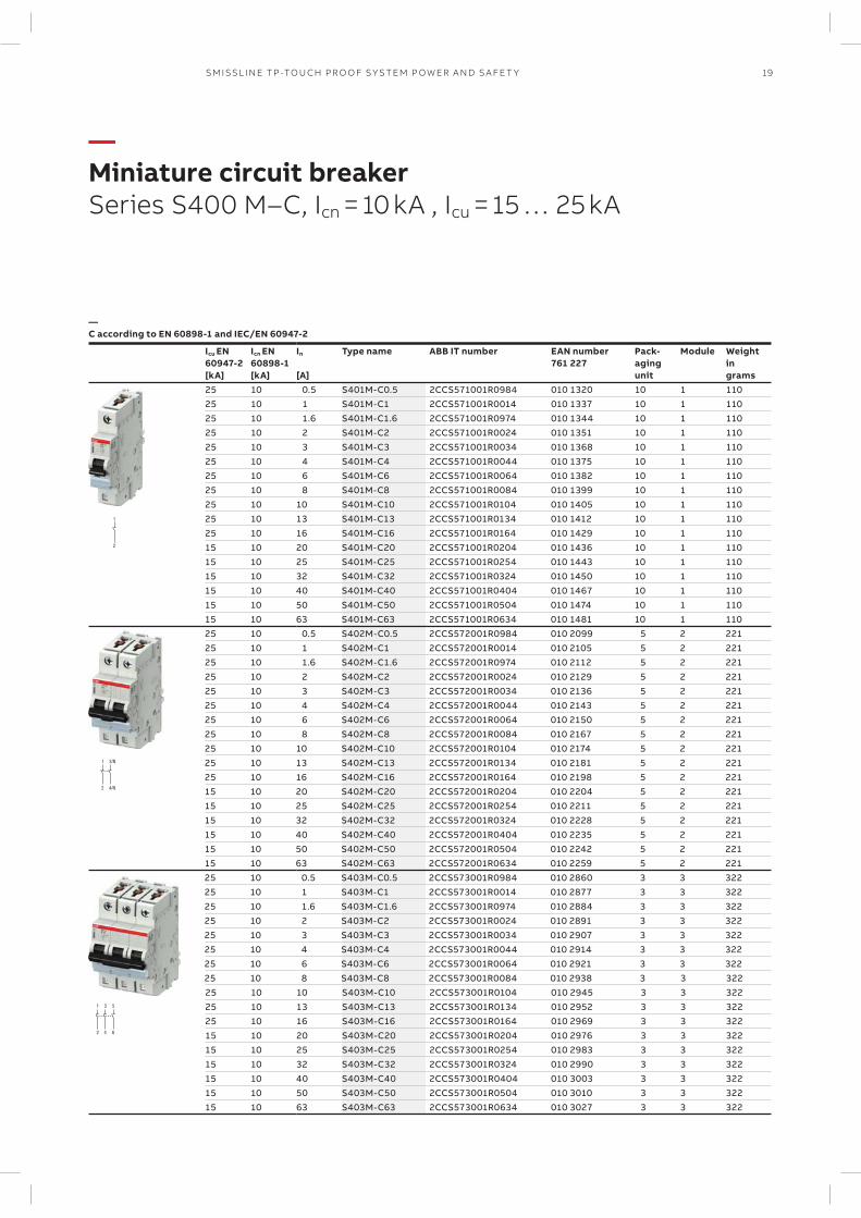
—Miniature circuit breakerSeries S400 M–C, Icn = 10 kA , Icu = 15 … 25 kA
—C according to EN 60898-1 and IEC/EN 60947-2
Icu EN60947-2[kA]
Icn EN60898-1[kA]
In
[A]
Type name ABB IT number EAN number761 227
Pack-agingunit
Module Weightingrams
25 10 0.5 S401M-C0.5 2CCS571001R0984 010 1320 10 1 11025 10 1 S401M-C1 2CCS571001R0014 010 1337 10 1 11025 10 1.6 S401M-C1.6 2CCS571001R0974 010 1344 10 1 11025 10 2 S401M-C2 2CCS571001R0024 010 1351 10 1 11025 10 3 S401M-C3 2CCS571001R0034 010 1368 10 1 11025 10 4 S401M-C4 2CCS571001R0044 010 1375 10 1 11025 10 6 S401M-C6 2CCS571001R0064 010 1382 10 1 11025 10 8 S401M-C8 2CCS571001R0084 010 1399 10 1 11025 10 10 S401M-C10 2CCS571001R0104 010 1405 10 1 11025 10 13 S401M-C13 2CCS571001R0134 010 1412 10 1 11025 10 16 S401M-C16 2CCS571001R0164 010 1429 10 1 11015 10 20 S401M-C20 2CCS571001R0204 010 1436 10 1 11015 10 25 S401M-C25 2CCS571001R0254 010 1443 10 1 11015 10 32 S401M-C32 2CCS571001R0324 010 1450 10 1 11015 10 40 S401M-C40 2CCS571001R0404 010 1467 10 1 11015 10 50 S401M-C50 2CCS571001R0504 010 1474 10 1 11015 10 63 S401M-C63 2CCS571001R0634 010 1481 10 1 11025 10 0.5 S402M-C0.5 2CCS572001R0984 010 2099 5 2 22125 10 1 S402M-C1 2CCS572001R0014 010 2105 5 2 22125 10 1.6 S402M-C1.6 2CCS572001R0974 010 2112 5 2 22125 10 2 S402M-C2 2CCS572001R0024 010 2129 5 2 22125 10 3 S402M-C3 2CCS572001R0034 010 2136 5 2 22125 10 4 S402M-C4 2CCS572001R0044 010 2143 5 2 22125 10 6 S402M-C6 2CCS572001R0064 010 2150 5 2 22125 10 8 S402M-C8 2CCS572001R0084 010 2167 5 2 22125 10 10 S402M-C10 2CCS572001R0104 010 2174 5 2 22125 10 13 S402M-C13 2CCS572001R0134 010 2181 5 2 22125 10 16 S402M-C16 2CCS572001R0164 010 2198 5 2 22115 10 20 S402M-C20 2CCS572001R0204 010 2204 5 2 22115 10 25 S402M-C25 2CCS572001R0254 010 2211 5 2 22115 10 32 S402M-C32 2CCS572001R0324 010 2228 5 2 22115 10 40 S402M-C40 2CCS572001R0404 010 2235 5 2 22115 10 50 S402M-C50 2CCS572001R0504 010 2242 5 2 22115 10 63 S402M-C63 2CCS572001R0634 010 2259 5 2 22125 10 0.5 S403M-C0.5 2CCS573001R0984 010 2860 3 3 32225 10 1 S403M-C1 2CCS573001R0014 010 2877 3 3 32225 10 1.6 S403M-C1.6 2CCS573001R0974 010 2884 3 3 32225 10 2 S403M-C2 2CCS573001R0024 010 2891 3 3 32225 10 3 S403M-C3 2CCS573001R0034 010 2907 3 3 32225 10 4 S403M-C4 2CCS573001R0044 010 2914 3 3 32225 10 6 S403M-C6 2CCS573001R0064 010 2921 3 3 32225 10 8 S403M-C8 2CCS573001R0084 010 2938 3 3 32225 10 10 S403M-C10 2CCS573001R0104 010 2945 3 3 32225 10 13 S403M-C13 2CCS573001R0134 010 2952 3 3 32225 10 16 S403M-C16 2CCS573001R0164 010 2969 3 3 32215 10 20 S403M-C20 2CCS573001R0204 010 2976 3 3 32215 10 25 S403M-C25 2CCS573001R0254 010 2983 3 3 32215 10 32 S403M-C32 2CCS573001R0324 010 2990 3 3 32215 10 40 S403M-C40 2CCS573001R0404 010 3003 3 3 32215 10 50 S403M-C50 2CCS573001R0504 010 3010 3 3 32215 10 63 S403M-C63 2CCS573001R0634 010 3027 3 3 322
1 3
2 4
5
6
1
2
20 TECH N I C A L C ATA LO G U E SM ISSL I N E TP -TO U CH PR O O F S Y S TEM P OW ER A N D S A FE T Y
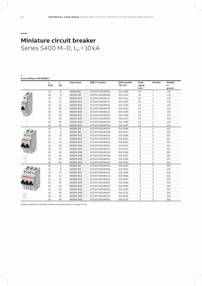
—Miniature circuit breakerSeries S400 M–D, Icn = 10 kA
—D according to EN 60898-1
Icn
[kA]In
[A]Type name ABB IT number EAN number
761 227Pack-agingunit
Module Weightingrams
10 6 S401M-D6 2CCS571001R0061 010 1498 10 1 11010 8 S401M-D8 2CCS571001R0081 010 1504 10 1 11010 10 S401M-D10 2CCS571001R0101 010 1511 10 1 11010 13 S401M-D13 2CCS571001R0131 010 1528 10 1 11010 16 S401M-D16 2CCS571001R0161 010 1535 10 1 11010 20 S401M-D20 2CCS571001R0201 010 1542 10 1 11010 25 S401M-D25 2CCS571001R0251 010 1559 10 1 11010 32 S401M-D32 2CCS571001R0321 010 1566 10 1 11010 40 S401M-D40 2CCS571001R0401 010 1573 10 1 11010 50 S401M-D50 2CCS571001R0501 010 1580 10 1 11010 63 S401M-D63 2CCS571001R0631 010 1597 10 1 11010 6 S402M-D6 2CCS572001R0061 010 2266 5 2 22110 8 S402M-D8 2CCS572001R0081 010 2273 5 2 22110 10 S402M-D10 2CCS572001R0101 010 2280 5 2 22110 13 S402M-D13 2CCS572001R0131 010 2297 5 2 22110 16 S402M-D16 2CCS572001R0161 010 2303 5 2 22110 20 S402M-D20 2CCS572001R0201 010 2310 5 2 22110 25 S402M-D25 2CCS572001R0251 010 2327 5 2 22110 32 S402M-D32 2CCS572001R0321 010 2334 5 2 22110 40 S402M-D40 2CCS572001R0401 010 2341 5 2 22110 50 S402M-D50 2CCS572001R0501 010 2358 5 2 22110 63 S402M-D63 2CCS572001R0631 010 2365 5 2 22110 6 S403M-D6 2CCS573001R0061 010 3034 3 3 32210 8 S403M-D8 2CCS573001R0081 010 3041 3 3 32210 10 S403M-D10 2CCS573001R0101 010 3058 3 3 32210 13 S403M-D13 2CCS573001R0131 010 3065 3 3 32210 16 S403M-D16 2CCS573001R0161 010 3072 3 3 32210 20 S403M-D20 2CCS573001R0201 010 3089 3 3 32210 25 S403M-D25 2CCS573001R0251 010 3096 3 3 32210 32 S403M-D32 2CCS573001R0321 010 3102 3 3 32210 40 S403M-D40 2CCS573001R0401 010 3119 3 3 32210 50 S403M-D50 2CCS573001R0501 010 3126 3 3 32210 63 S403M-D63 2CCS573001R0631 010 3133 3 3 322
Ordering details for auxiliary switch and signal contacts on page 41– 45
1 3
2 4
5
6
1
2
21SM ISSL I N E TP -TO U CH PR O O F S Y S TEM P OW ER A N D S A FE T Y
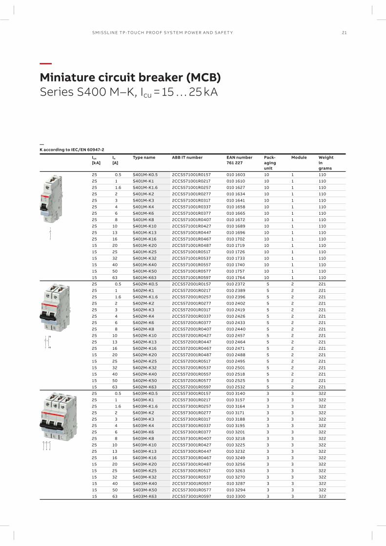
—Miniature circuit breaker (MCB)Series S400 M–K, Icu = 15 … 25 kA
—K according to IEC/EN 60947-2
Icn
[kA]In
[A]Type name ABB IT number EAN number
761 227Pack-agingunit
Module Weightingrams
25 0.5 S401M-K0.5 2CCS571001R0157 010 1603 10 1 11025 1 S401M-K1 2CCS571001R0217 010 1610 10 1 11025 1.6 S401M-K1.6 2CCS571001R0257 010 1627 10 1 11025 2 S401M-K2 2CCS571001R0277 010 1634 10 1 11025 3 S401M-K3 2CCS571001R0317 010 1641 10 1 11025 4 S401M-K4 2CCS571001R0337 010 1658 10 1 11025 6 S401M-K6 2CCS571001R0377 010 1665 10 1 11025 8 S401M-K8 2CCS571001R0407 010 1672 10 1 11025 10 S401M-K10 2CCS571001R0427 010 1689 10 1 11025 13 S401M-K13 2CCS571001R0447 010 1696 10 1 11025 16 S401M-K16 2CCS571001R0467 010 1702 10 1 11015 20 S401M-K20 2CCS571001R0487 010 1719 10 1 11015 25 S401M-K25 2CCS571001R0517 010 1726 10 1 11015 32 S401M-K32 2CCS571001R0537 010 1733 10 1 11015 40 S401M-K40 2CCS571001R0557 010 1740 10 1 11015 50 S401M-K50 2CCS571001R0577 010 1757 10 1 11015 63 S401M-K63 2CCS571001R0597 010 1764 10 1 11025 0.5 S402M-K0.5 2CCS572001R0157 010 2372 5 2 22125 1 S402M-K1 2CCS572001R0217 010 2389 5 2 22125 1.6 S402M-K1.6 2CCS572001R0257 010 2396 5 2 22125 2 S402M-K2 2CCS572001R0277 010 2402 5 2 22125 3 S402M-K3 2CCS572001R0317 010 2419 5 2 22125 4 S402M-K4 2CCS572001R0337 010 2426 5 2 22125 6 S402M-K6 2CCS572001R0377 010 2433 5 2 22125 8 S402M-K8 2CCS572001R0407 010 2440 5 2 22125 10 S402M-K10 2CCS572001R0427 010 2457 5 2 22125 13 S402M-K13 2CCS572001R0447 010 2464 5 2 22125 16 S402M-K16 2CCS572001R0467 010 2471 5 2 22115 20 S402M-K20 2CCS572001R0487 010 2488 5 2 22115 25 S402M-K25 2CCS572001R0517 010 2495 5 2 22115 32 S402M-K32 2CCS572001R0537 010 2501 5 2 22115 40 S402M-K40 2CCS572001R0557 010 2518 5 2 22115 50 S402M-K50 2CCS572001R0577 010 2525 5 2 22115 63 S402M-K63 2CCS572001R0597 010 2532 5 2 22125 0.5 S403M-K0.5 2CCS573001R0157 010 3140 3 3 32225 1 S403M-K1 2CCS573001R0217 010 3157 3 3 32225 1.6 S403M-K1.6 2CCS573001R0257 010 3164 3 3 32225 2 S403M-K2 2CCS573001R0277 010 3171 3 3 32225 3 S403M-K3 2CCS573001R0317 010 3188 3 3 32225 4 S403M-K4 2CCS573001R0337 010 3195 3 3 32225 6 S403M-K6 2CCS573001R0377 010 3201 3 3 32225 8 S403M-K8 2CCS573001R0407 010 3218 3 3 32225 10 S403M-K10 2CCS573001R0427 010 3225 3 3 32225 13 S403M-K13 2CCS573001R0447 010 3232 3 3 32225 16 S403M-K16 2CCS573001R0467 010 3249 3 3 32215 20 S403M-K20 2CCS573001R0487 010 3256 3 3 32215 25 S403M-K25 2CCS573001R0517 010 3263 3 3 32215 32 S403M-K32 2CCS573001R0537 010 3270 3 3 32215 40 S403M-K40 2CCS573001R0557 010 3287 3 3 32215 50 S403M-K50 2CCS573001R0577 010 3294 3 3 32215 63 S403M-K63 2CCS573001R0597 010 3300 3 3 322
22 TECH N I C A L C ATA LO G U E SM ISSL I N E TP -TO U CH PR O O F S Y S TEM P OW ER A N D S A FE T Y
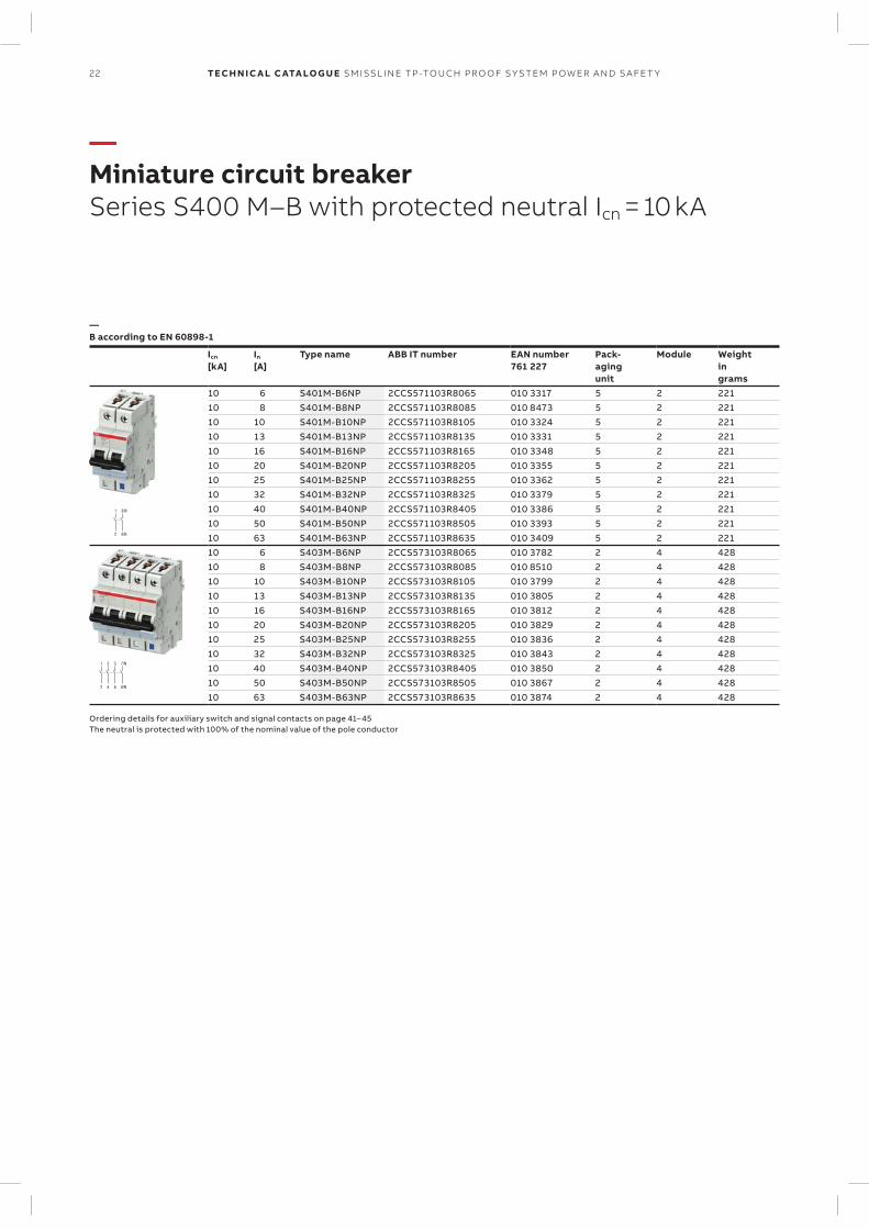
—Miniature circuit breakerSeries S400 M–B with protected neutral Icn = 10 kA
—B according to EN 60898-1
Icn
[kA]In
[A]Type name ABB IT number EAN number
761 227Pack-agingunit
Module Weightingrams
10 6 S401M-B6NP 2CCS571103R8065 010 3317 5 2 22110 8 S401M-B8NP 2CCS571103R8085 010 8473 5 2 22110 10 S401M-B10NP 2CCS571103R8105 010 3324 5 2 22110 13 S401M-B13NP 2CCS571103R8135 010 3331 5 2 22110 16 S401M-B16NP 2CCS571103R8165 010 3348 5 2 22110 20 S401M-B20NP 2CCS571103R8205 010 3355 5 2 22110 25 S401M-B25NP 2CCS571103R8255 010 3362 5 2 22110 32 S401M-B32NP 2CCS571103R8325 010 3379 5 2 22110 40 S401M-B40NP 2CCS571103R8405 010 3386 5 2 22110 50 S401M-B50NP 2CCS571103R8505 010 3393 5 2 22110 63 S401M-B63NP 2CCS571103R8635 010 3409 5 2 22110 6 S403M-B6NP 2CCS573103R8065 010 3782 2 4 42810 8 S403M-B8NP 2CCS573103R8085 010 8510 2 4 42810 10 S403M-B10NP 2CCS573103R8105 010 3799 2 4 42810 13 S403M-B13NP 2CCS573103R8135 010 3805 2 4 42810 16 S403M-B16NP 2CCS573103R8165 010 3812 2 4 42810 20 S403M-B20NP 2CCS573103R8205 010 3829 2 4 42810 25 S403M-B25NP 2CCS573103R8255 010 3836 2 4 42810 32 S403M-B32NP 2CCS573103R8325 010 3843 2 4 42810 40 S403M-B40NP 2CCS573103R8405 010 3850 2 4 42810 50 S403M-B50NP 2CCS573103R8505 010 3867 2 4 42810 63 S403M-B63NP 2CCS573103R8635 010 3874 2 4 428
Ordering details for auxiliary switch and signal contacts on page 41– 45 The neutral is protected with 100% of the nominal value of the pole conductor
23SM ISSL I N E TP -TO U CH PR O O F S Y S TEM P OW ER A N D S A FE T Y
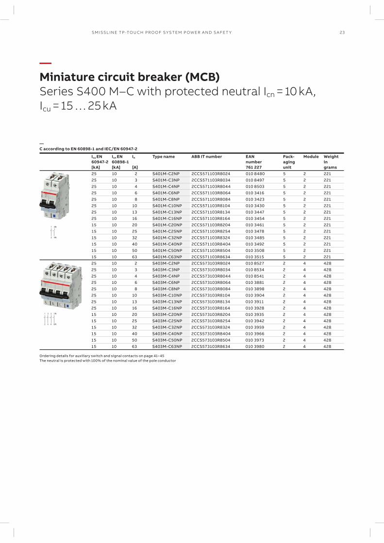
—Miniature circuit breaker (MCB)Series S400 M–C with protected neutral Icn = 10 kA, Icu = 15 … 25 kA
—C according to EN 60898-1 and IEC/EN 60947-2
Icu EN60947-2[kA]
Icn EN60898-1[kA]
In
[A]
Type name ABB IT number EANnumber761 227
Pack-agingunit
Module Weightingrams
25 10 2 S401M-C2NP 2CCS571103R8024 010 8480 5 2 22125 10 3 S401M-C3NP 2CCS571103R8034 010 8497 5 2 22125 10 4 S401M-C4NP 2CCS571103R8044 010 8503 5 2 22125 10 6 S401M-C6NP 2CCS571103R8064 010 3416 5 2 22125 10 8 S401M-C8NP 2CCS571103R8084 010 3423 5 2 22125 10 10 S401M-C10NP 2CCS571103R8104 010 3430 5 2 22125 10 13 S401M-C13NP 2CCS571103R8134 010 3447 5 2 22125 10 16 S401M-C16NP 2CCS571103R8164 010 3454 5 2 22115 10 20 S401M-C20NP 2CCS571103R8204 010 3461 5 2 22115 10 25 S401M-C25NP 2CCS571103R8254 010 3478 5 2 22115 10 32 S401M-C32NP 2CCS571103R8324 010 3485 5 2 22115 10 40 S401M-C40NP 2CCS571103R8404 010 3492 5 2 22115 10 50 S401M-C50NP 2CCS571103R8504 010 3508 5 2 22115 10 63 S401M-C63NP 2CCS571103R8634 010 3515 5 2 22125 10 2 S403M-C2NP 2CCS573103R8024 010 8527 2 4 42825 10 3 S403M-C3NP 2CCS573103R8034 010 8534 2 4 42825 10 4 S403M-C4NP 2CCS573103R8044 010 8541 2 4 42825 10 6 S403M-C6NP 2CCS573103R8064 010 3881 2 4 42825 10 8 S403M-C8NP 2CCS573103R8084 010 3898 2 4 42825 10 10 S403M-C10NP 2CCS573103R8104 010 3904 2 4 42825 10 13 S403M-C13NP 2CCS573103R8134 010 3911 2 4 42825 10 16 S403M-C16NP 2CCS573103R8164 010 3928 2 4 42815 10 20 S403M-C20NP 2CCS573103R8204 010 3935 2 4 42815 10 25 S403M-C25NP 2CCS573103R8254 010 3942 2 4 42815 10 32 S403M-C32NP 2CCS573103R8324 010 3959 2 4 42815 10 40 S403M-C40NP 2CCS573103R8404 010 3966 2 4 42815 10 50 S403M-C50NP 2CCS573103R8504 010 3973 2 4 42815 10 63 S403M-C63NP 2CCS573103R8634 010 3980 2 4 428
Ordering details for auxiliary switch and signal contacts on page 41– 45 The neutral is protected with 100% of the nominal value of the pole conductor
24 TECH N I C A L C ATA LO G U E SM ISSL I N E TP -TO U CH PR O O F S Y S TEM P OW ER A N D S A FE T Y
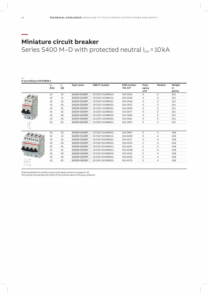
—Miniature circuit breakerSeries S400 M–D with protected neutral Icn = 10 kA
—D according to EN 60898-1
Icn
[kA]In
[A]Type name ABB IT number EAN number
761 227Pack-agingunit
Module Weightingrams
10 10 S401M-D10NP 2CCS571103R8101 010 3522 5 2 22110 13 S401M-D13NP 2CCS571103R8131 010 3539 5 2 22110 16 S401M-D16NP 2CCS571103R8161 010 3546 5 2 22110 20 S401M-D20NP 2CCS571103R8201 010 3553 5 2 22110 25 S401M-D25NP 2CCS571103R8251 010 3560 5 2 22110 32 S401M-D32NP 2CCS571103R8321 010 3577 5 2 22110 40 S401M-D40NP 2CCS571103R8401 010 3584 5 2 22110 50 S401M-D50NP 2CCS571103R8501 010 3591 5 2 22110 63 S401M-D63NP 2CCS571103R8631 010 3607 5 2 221
10 10 S403M-D10NP 2CCS573103R8101 010 3997 2 4 42810 13 S403M-D13NP 2CCS573103R8131 010 4000 2 4 42810 16 S403M-D16NP 2CCS573103R8161 010 4017 2 4 42810 20 S403M-D20NP 2CCS573103R8201 010 4024 2 4 42810 25 S403M-D25NP 2CCS573103R8251 010 4031 2 4 42810 32 S403M-D32NP 2CCS573103R8321 010 4048 2 4 42810 40 S403M-D40NP 2CCS573103R8401 010 4055 2 4 42810 50 S403M-D50NP 2CCS573103R8501 010 4062 2 4 42810 63 S403M-D63NP 2CCS573103R8631 010 4079 2 4 428
Ordering details for auxiliary switch and signal contacts on page 41– 45 The neutral is protected with 100% of the nominal value of the pole conductor
25SM ISSL I N E TP -TO U CH PR O O F S Y S TEM P OW ER A N D S A FE T Y
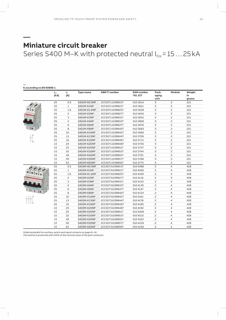
—Miniature circuit breaker Series S400 M–K with protected neutral Icu = 15 … 25 kA
—K according to EN 60898-1
Icu
[kA]In
[A]Type name ABB IT number EAN number
761 227Pack-agingunit
Module Weightingrams
25 0.5 S401M-K0.5NP 2CCS571103R8157 010 3614 5 2 22125 1 S401M-K1NP 2CCS571103R8217 010 3621 5 2 22125 1.6 S401M-K1.6NP 2CCS571103R8257 010 3638 5 2 22125 2 S401M-K2NP 2CCS571103R8277 010 3645 5 2 22125 3 S401M-K3NP 2CCS571103R8317 010 3652 5 2 22125 4 S401M-K4NP 2CCS571103R8337 010 3669 5 2 22125 6 S401M-K6NP 2CCS571103R8377 010 3676 5 2 22125 8 S401M-K8NP 2CCS571103R8407 010 3683 5 2 22125 10 S401M-K10NP 2CCS571103R8427 010 3690 5 2 22125 13 S401M-K13NP 2CCS571103R8447 010 3706 5 2 22125 16 S401M-K16NP 2CCS571103R8467 010 3713 5 2 22115 20 S401M-K20NP 2CCS571103R8487 010 3720 5 2 22115 25 S401M-K25NP 2CCS571103R8517 010 3737 5 2 22115 32 S401M-K32NP 2CCS571103R8537 010 3744 5 2 22115 40 S401M-K40NP 2CCS571103R8557 010 3751 5 2 22115 50 S401M-K50NP 2CCS571103R8577 010 3768 5 2 22115 63 S401M-K63NP 2CCS571103R8597 010 3775 5 2 22125 0.5 S403M-K0.5NP 2CCS573103R8157 010 4086 2 4 42825 1 S403M-K1NP 2CCS573103R8217 010 4093 2 4 42825 1.6 S403M-K1.6NP 2CCS573103R8257 010 4109 2 4 42825 2 S403M-K2NP 2CCS573103R8277 010 4116 2 4 42825 3 S403M-K3NP 2CCS573103R8317 010 4123 2 4 42825 4 S403M-K4NP 2CCS573103R8337 010 4130 2 4 42825 6 S403M-K6NP 2CCS573103R8377 010 4147 2 4 42825 8 S403M-K8NP 2CCS573103R8407 010 4154 2 4 42825 10 S403M-K10NP 2CCS573103R8427 010 4161 2 4 42825 13 S403M-K13NP 2CCS573103R8447 010 4178 2 4 42825 16 S403M-K16NP 2CCS573103R8467 010 4185 2 4 42815 20 S403M-K20NP 2CCS573103R8487 010 4192 2 4 42815 25 S403M-K25NP 2CCS573103R8517 010 4208 2 4 42815 32 S403M-K32NP 2CCS573103R8537 010 4215 2 4 42815 40 S403M-K40NP 2CCS573103R8557 010 4222 2 4 42815 50 S403M-K50NP 2CCS573103R8577 010 4239 2 4 42815 63 S403M-K63NP 2CCS573103R8597 010 4246 2 4 428
Ordering details for auxiliary switch and signal contacts on page 41– 45 The neutral is protected with 100% of the nominal value of the pole conductor
1
+2
1 P 220 V=
2 P 440 V=
1 3
+2 4–
1
2
1
2
3
4
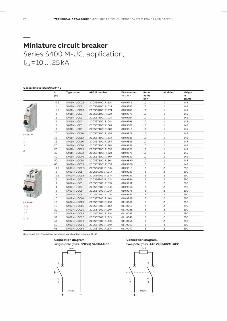
Connection diagram, Connection diagram, single-pole (max. 220 V=) S401M-UCC two-pole (max. 440 V=) S402M-UCC
Load
Mains
Load
Mains
26 TECH N I C A L C ATA LO G U E SM ISSL I N E TP -TO U CH PR O O F S Y S TEM P OW ER A N D S A FE T Y
—Miniature circuit breakerSeries S400 M-UC, application, Icu = 10 … 25 kA
—C according to IEC/EN 60947-2
In
[A]Type name ABB IT number EAN number
761 227Pack-agingunit
Module Weightingrams
0.5 S401M-UCC0.5 2CCS561001R1984 010 9746 10 1 145 1 S401M-UCC1 2CCS561001R1014 010 9753 10 1 145 1.6 S401M-UCC1.6 2CCS561001R1974 010 9760 10 1 145 2 S401M-UCC2 2CCS561001R1024 010 9777 10 1 145 3 S401M-UCC3 2CCS571001R1034 010 9784 10 1 145 4 S401M-UCC4 2CCS571001R1044 010 9791 10 1 145 6 S401M-UCC6 2CCS571001R1064 010 9807 10 1 145 8 S401M-UCC8 2CCS571001R1084 010 9814 10 1 145
10 S401M-UCC10 2CCS571001R1104 010 9821 10 1 145
13 S401M-UCC13 2CCS571001R1134 010 9838 10 1 14516 S401M-UCC16 2CCS571001R1164 010 9845 10 1 14520 S401M-UCC20 2CCS571001R1204 010 9852 10 1 14525 S401M-UCC25 2CCS571001R1254 010 9869 10 1 14532 S401M-UCC32 2CCS571001R1324 010 9876 10 1 14540 S401M-UCC40 2CCS571001R1404 010 9883 10 1 14550 S401M-UCC50 2CCS571001R1504 010 9890 10 1 14563 S401M-UCC63 2CCS571001R1634 010 9906 10 1 145 0.5 S402M-UCC0.5 2CCS562001R1984 010 9913 5 2 290 1 S402M-UCC1 2CCS562001R1014 010 9920 5 2 290 1.6 S402M-UCC1.6 2CCS562001R1974 010 9937 5 2 290 2 S402M-UCC2 2CCS562001R1024 010 9944 5 2 290 3 S402M-UCC3 2CCS572001R1034 010 9951 5 2 290 4 S402M-UCC4 2CCS572001R1044 010 9968 5 2 290 6 S402M-UCC6 2CCS572001R1064 010 9975 5 2 290 8 S402M-UCC8 2CCS572001R1084 010 9982 5 2 29010 S402M-UCC10 2CCS572001R1104 010 9999 5 2 29013 S402M-UCC13 2CCS572001R1134 011 0001 5 2 29016 S402M-UCC16 2CCS572001R1164 011 0018 5 2 29020 S402M-UCC20 2CCS572001R1204 011 0025 5 2 29025 S402M-UCC25 2CCS572001R1254 011 0032 5 2 29032 S402M-UCC32 2CCS572001R1324 011 0049 5 2 29040 S402M-UCC40 2CCS572001R1404 011 0056 5 2 29050 S402M-UCC50 2CCS572001R1504 011 0063 5 2 29063 S402M-UCC63 2CCS572001R1634 011 0070 5 2 290
Ordering details for auxiliary switch and signal contacts on page 41– 45
1
+2
1 P 220 V=
2 P 440 V=
1 3
+2 4–
1
2
1
2
3
4
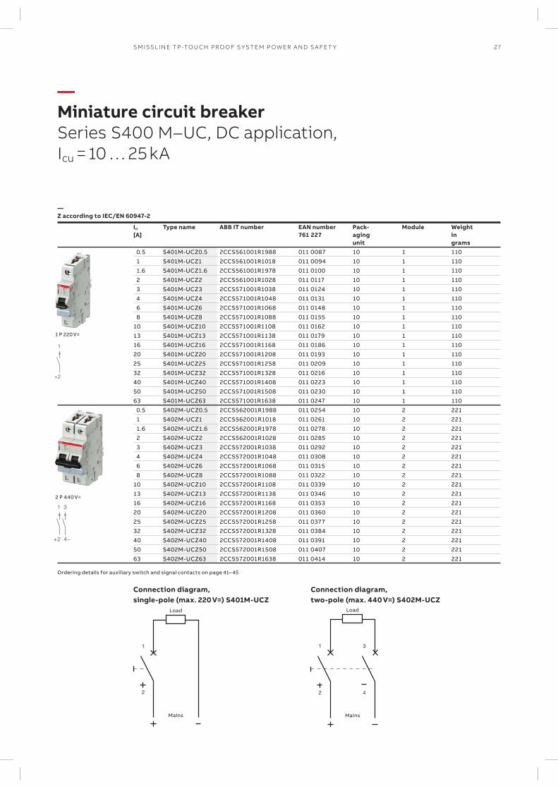
Connection diagram, Connection diagram, single-pole (max. 220 V=) S401M-UCZ two-pole (max. 440 V=) S402M-UCZ
Load
Mains
Load
Mains
27SM ISSL I N E TP -TO U CH PR O O F S Y S TEM P OW ER A N D S A FE T Y
—Miniature circuit breakerSeries S400 M–UC, DC application, Icu = 10 … 25 kA
—Z according to IEC/EN 60947-2
In
[A]Type name ABB IT number EAN number
761 227Pack-agingunit
Module Weightingrams
0.5 S401M-UCZ0.5 2CCS561001R1988 011 0087 10 1 110 1 S401M-UCZ1 2CCS561001R1018 011 0094 10 1 110 1.6 S401M-UCZ1.6 2CCS561001R1978 011 0100 10 1 110 2 S401M-UCZ2 2CCS561001R1028 011 0117 10 1 110 3 S401M-UCZ3 2CCS571001R1038 011 0124 10 1 110 4 S401M-UCZ4 2CCS571001R1048 011 0131 10 1 110 6 S401M-UCZ6 2CCS571001R1068 011 0148 10 1 110 8 S401M-UCZ8 2CCS571001R1088 011 0155 10 1 11010 S401M-UCZ10 2CCS571001R1108 011 0162 10 1 11013 S401M-UCZ13 2CCS571001R1138 011 0179 10 1 11016 S401M-UCZ16 2CCS571001R1168 011 0186 10 1 11020 S401M-UCZ20 2CCS571001R1208 011 0193 10 1 11025 S401M-UCZ25 2CCS571001R1258 011 0209 10 1 11032 S401M-UCZ32 2CCS571001R1328 011 0216 10 1 11040 S401M-UCZ40 2CCS571001R1408 011 0223 10 1 11050 S401M-UCZ50 2CCS571001R1508 011 0230 10 1 11063 S401M-UCZ63 2CCS571001R1638 011 0247 10 1 110 0.5 S402M-UCZ0.5 2CCS562001R1988 011 0254 10 2 221 1 S402M-UCZ1 2CCS562001R1018 011 0261 10 2 221 1.6 S402M-UCZ1.6 2CCS562001R1978 011 0278 10 2 221 2 S402M-UCZ2 2CCS562001R1028 011 0285 10 2 221 3 S402M-UCZ3 2CCS572001R1038 011 0292 10 2 221 4 S402M-UCZ4 2CCS572001R1048 011 0308 10 2 221 6 S402M-UCZ6 2CCS572001R1068 011 0315 10 2 221 8 S402M-UCZ8 2CCS572001R1088 011 0322 10 2 22110 S402M-UCZ10 2CCS572001R1108 011 0339 10 2 22113 S402M-UCZ13 2CCS572001R1138 011 0346 10 2 22116 S402M-UCZ16 2CCS572001R1168 011 0353 10 2 22120 S402M-UCZ20 2CCS572001R1208 011 0360 10 2 22125 S402M-UCZ25 2CCS572001R1258 011 0377 10 2 22132 S402M-UCZ32 2CCS572001R1328 011 0384 10 2 22140 S402M-UCZ40 2CCS572001R1408 011 0391 10 2 22150 S402M-UCZ50 2CCS572001R1508 011 0407 10 2 22163 S402M-UCZ63 2CCS572001R1638 011 0414 10 2 221
Ordering details for auxiliary switch and signal contacts on page 41– 45
1/2 3/4/N
2/1 4/3/N
28 TECH N I C A L C ATA LO G U E SM ISSL I N E TP -TO U CH PR O O F S Y S TEM P OW ER A N D S A FE T Y
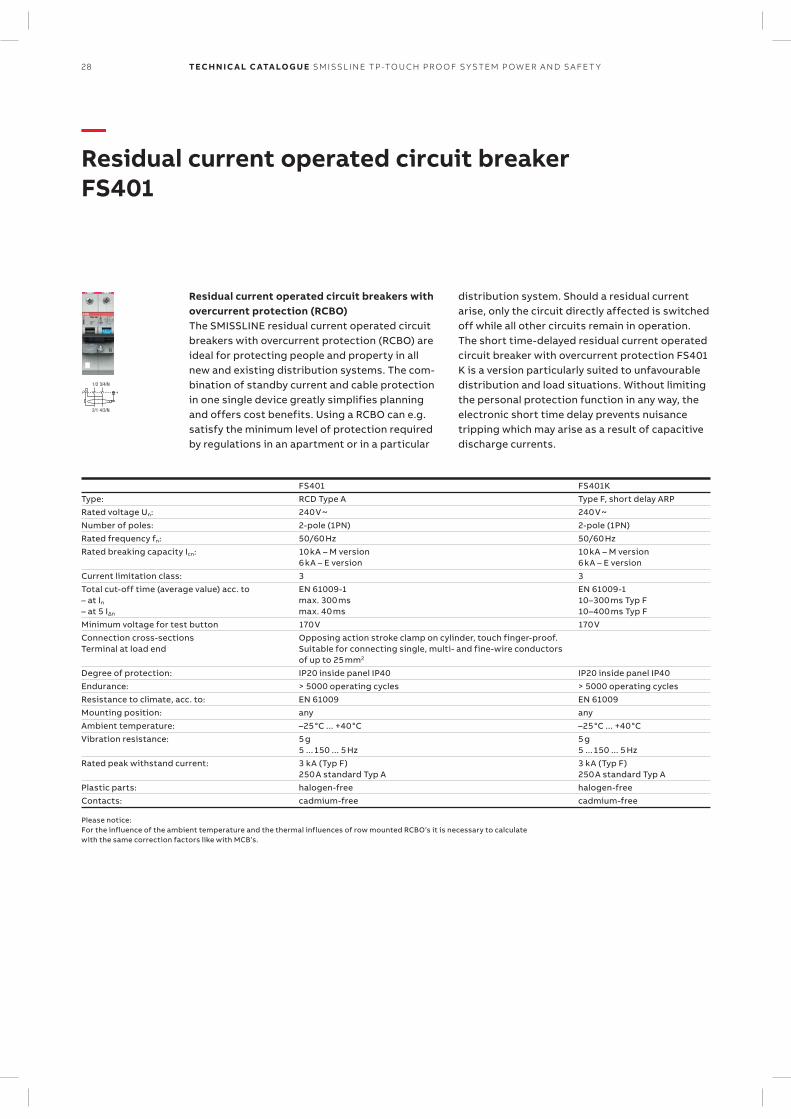
—Residual current operated circuit breaker FS401
Residual current operated circuit breakers with overcurrent protection (RCBO)The SMISSLINE residual current operated circuit breakers with overcurrent protection (RCBO) are ideal for protecting people and property in all new and existing distribution systems. The com-bination of standby current and cable protection in one single device greatly simplifies planning and offers cost benefits. Using a RCBO can e.g. satisfy the minimum level of protection required by regulations in an apartment or in a particular
distribution system. Should a residual current arise, only the circuit directly affected is switched off while all other circuits remain in operation.The short time-delayed residual current operated circuit breaker with overcurrent protection FS401 K is a version particularly suited to unfavourable distribution and load situations. Without limiting the personal protection function in any way, the electronic short time delay prevents nuisance tripping which may arise as a result of capacitive discharge currents.
FS401 FS401KType: RCD Type A Type F, short delay ARPRated voltage Un: 240 V ~ 240 V ~Number of poles: 2-pole (1PN) 2-pole (1PN)Rated frequency fn: 50/60 Hz 50/60 HzRated breaking capacity Icn: 10 kA – M version
6 kA – E version10 kA – M version 6 kA – E version
Current limitation class: 3 3Total cut-off time (average value) acc. to– at In
– at 5 I∆n
EN 61009-1max. 300 msmax. 40 ms
EN 61009-110–300 ms Typ F10–400 ms Typ F
Minimum voltage for test button 170 V 170 VConnection cross-sectionsTerminal at load end
Opposing action stroke clamp on cylinder, touch finger-proof. Suitable for connecting single, multi- and fine-wire conductors of up to 25 mm2
Degree of protection: IP20 inside panel IP40 IP20 inside panel IP40Endurance: > 5000 operating cycles > 5000 operating cyclesResistance to climate, acc. to: EN 61009 EN 61009Mounting position: any anyAmbient temperature: –25°C ... +40°C –25°C ... +40°CVibration resistance: 5 g
5 ...150 ... 5 Hz5 g5 ...150 ... 5 Hz
Rated peak withstand current: 3 kA (Typ F)250 A standard Typ A
3 kA (Typ F)250 A standard Typ A
Plastic parts: halogen-free halogen-freeContacts: cadmium-free cadmium-free
Please notice:For the influence of the ambient temperature and the thermal influences of row mounted RCBO’s it is necessary to calculatewith the same correction factors like with MCB’s.
29SM ISSL I N E TP -TO U CH PR O O F S Y S TEM P OW ER A N D S A FE T Y
—Residual current operated circuit breaker with overcurrent protectionSeries FS401 LN, Type A
—B, 6 kA according to EN 61009-1
I∆n
[mA]In
[A]Icn
[kA]Type name ABB IT number EAN
number761 227
Pack-agingunit
Module Weightingrams
new 30 10 6 FS401E-B10/0.03 2CCL562111E1105 147 2825 1 2 20030 13 6 FS401E-B13/0.03 2CCL562111E0135 010 8558 1 2 20030 16 6 FS401E-B16/0.03 2CCL562111E0165 010 8565 1 2 20030 20 6 FS401E-B20/0.03 2CCL562111E0205 010 9692 1 2 20030 25 6 FS401E-B25/0.03 2CCL562111E0255 010 9708 1 2 20030 32 6 FS401E-B32/0.03 2CCL562111E0325 010 9715 1 2 200
—C, 6 kA according to EN 61009-1
I∆n
[mA]In
[A]Icn
[kA]Type name ABB IT number EAN
number761 227
Pack-agingunit
Module Weightingrams
new 30 6 6 FS401E-C6/0.03 2CCL562111E1064 147 2788 1 2 200new 30 10 6 FS401E-C10/0.03 2CCL562111E1104 147 2801 1 2 200
30 13 6 FS401E-C13/0.03 2CCL562111E0134 010 8572 1 2 20030 16 6 FS401E-C16/0.03 2CCL562111E0164 010 8589 1 2 20030 20 6 FS401E-C20/0.03 2CCL562110E0204 010 4574 1 2 20030 25 6 FS401E-C25/0.03 2CCL562110E0254 010 4581 1 2 20030 32 6 FS401E-C32/0.03 2CCL562110E0324 010 4598 1 2 200
—B, 10 kA according to EN 61009-1
I∆n
[mA]In
[A]Icn
[kA]Type name ABB IT number EAN
number761 227
Pack-agingunit
Module Weightingrams
30 6 10 FS401M-B6/0.03 2CCL562110E1065 147 2641 1 2 20030 10 10 FS401M-B10/0.03 2CCL562110E0105 010 9685 1 2 20030 13 10 FS401M-B13/0.03 2CCL562110E0135 010 4505 1 2 20030 16 10 FS401M-B16/0.03 2CCL562110E0165 010 4512 1 2 200
new 30 20 10 FS401M-B20/0.03 2CCL562110E1205 147 2689 1 2 200new 30 25 10 FS401M-B25/0.03 2CCL562110E1255 147 2726 1 2 200new 30 32 10 FS401M-B32/0.03 2CCL562110E1325 147 2764 1 2 200
—C, 10 kA according to EN 61009-1
I∆n
[mA]In
[A]Icn
[kA]Type name ABB IT number EAN
number761 227
Pack-agingunit
Module Weightingrams
30 6 10 FS401M-C6/0.03 2CCL562010E0064 140 6905 1 2 20030 10 10 FS401M-C10/0.03 2CCL562110E0104 010 4543 1 2 20030 13 10 FS401M-C13/0.03 2CCL562110E0134 010 4550 1 2 20030 16 10 FS401M-C16/0.03 2CCL562110E0164 010 4567 1 2 200
new 30 20 10 FS401M-C20/0.03 2CCL562110E1204 147 2665 1 2 200new 30 25 10 FS401M-C25/0.03 2CCL562110E1254 147 2702 1 2 200new 30 32 10 FS401M-C32/0.03 2CCL562110E1324 147 2740 1 2 200
Ordering details for auxiliary switch and signal contacts on page 41– 45

30 TECH N I C A L C ATA LO G U E SM ISSL I N E TP -TO U CH PR O O F S Y S TEM P OW ER A N D S A FE T Y
—Residual current operated circuit breaker with overcurrent protectionSeries FS401 LN, Typ F and short delay
—B, 10 kA according to EN 61009-1
I∆n
[mA]In
[A]Icn
[kA]Type name ABB IT number EAN
number761 227
Pack-agingunit
Module Weightingrams
new 30 6 10 FS401MK-B6/0.03 2CCL562130E1035 147 2849 1 2 200new 30 10 10 FS401MK-B10/0.03 2CCL562310E1105 147 2887 1 2 200new 30 13 10 FS401MK-B13/0.03 2CCL562310E1135 147 2900 1 2 200new 30 16 10 FS401MK-B16/0.03 2CCL562310E1165 147 2924 1 2 200new 30 20 10 FS401MK-B20/0.03 2CCL562310E1205 147 2962 1 2 200new 30 25 10 FS401MK-B25/0.03 2CCL562310E1255 147 3006 1 2 200new 30 32 10 FS401MK-B32/0.03 2CCL562310E1325 147 3044 1 2 200
—C 10 kA according to EN 61009-1
I∆n
[mA]In
[A]Icn
[kA]Type name ABB IT number EAN
number761 227
Pack-agingunit
Module Weightingrams
new 30 6 10 FS401MK-C6/0.03 2CCL562330E1064 140 4031 1 2 200new 30 10 10 FS401MK-C10/0.03 2CCL562310E0104 140 4031 1 2 200new 30 13 10 FS401MK-C13/0.03 2CCL562310E0134 010 4604 1 2 200new 30 16 10 FS401MK-C16/0.03 2CCL562310E0164 010 4611 1 2 200new 30 20 10 FS401MK-C20/0.03 2CCL562310E1204 010 4642 1 2 200new 30 25 10 FS401MK-C25/0.03 2CCL562310E1254 010 4642 1 2 200new 30 32 10 FS401MK-C32/0.03 2CCL562310E1324 010 4642 1 2 200
—C, 10 kA according to EN 61009-1
I∆n
[mA]In
[A]Icn
[kA]Type name ABB IT number EAN
number761 227
Pack-agingunit
Module Weightingrams
new 100 6 10 FS401M-C6/0.1 2CCL562120E0064 142 4534 1 2 200new 100 10 10 FS401M-C10/0.1 2CCL562120E0104 141 3217 1 2 200new 100 13 10 FS401M-C13/0.1 2CCL562120E0134 149 0706 1 2 200new 100 16 10 FS401M-C16/0.1 2CCL562120E0164 142 1618 1 2 200new 100 20 10 FS401M-C20/0.1 2CCL562122E0204 149 0720 1 2 200new 100 25 10 FS401M-C25/0.1 2CCL562122E0254 149 0744 1 2 200new 100 32 10 FS401M-C32/0.1 2CCL562122E0324 149 0768 1 2 200
—C, 10 kA according to EN 61009-1
I∆n
[mA]In
[A]Icn
[kA]Type name ABB IT number EAN
number761 227
Pack-agingunit
Module Weightingrams
new 300 6 10 FS401MK-C6/0.3 2CCL562130E3034 147 3068 1 2 200new 300 10 10 FS401MK-C10/0.3 2CCL562330E1104 147 3082 1 2 200new 300 13 10 FS401MK-C13/0.3 2CCL562330E1134 147 3105 1 2 200new 300 16 10 FS401MK-C16/0.3 2CCL562330E1164 147 3143 1 2 200new 300 20 10 FS401MK-C20/0.3 2CCL562330E1204 147 3181 1 2 200new 300 25 10 FS401MK-C25/0.3 2CCL562330E1254 147 3228 1 2 200new 300 32 10 FS401MK-C32/0.3 2CCL562330E1324 147 3266 1 2 200
Ordering details for auxiliary switch and signal contacts on page 41– 45
31SM ISSL I N E TP -TO U CH PR O O F S Y S TEM P OW ER A N D S A FE T Y
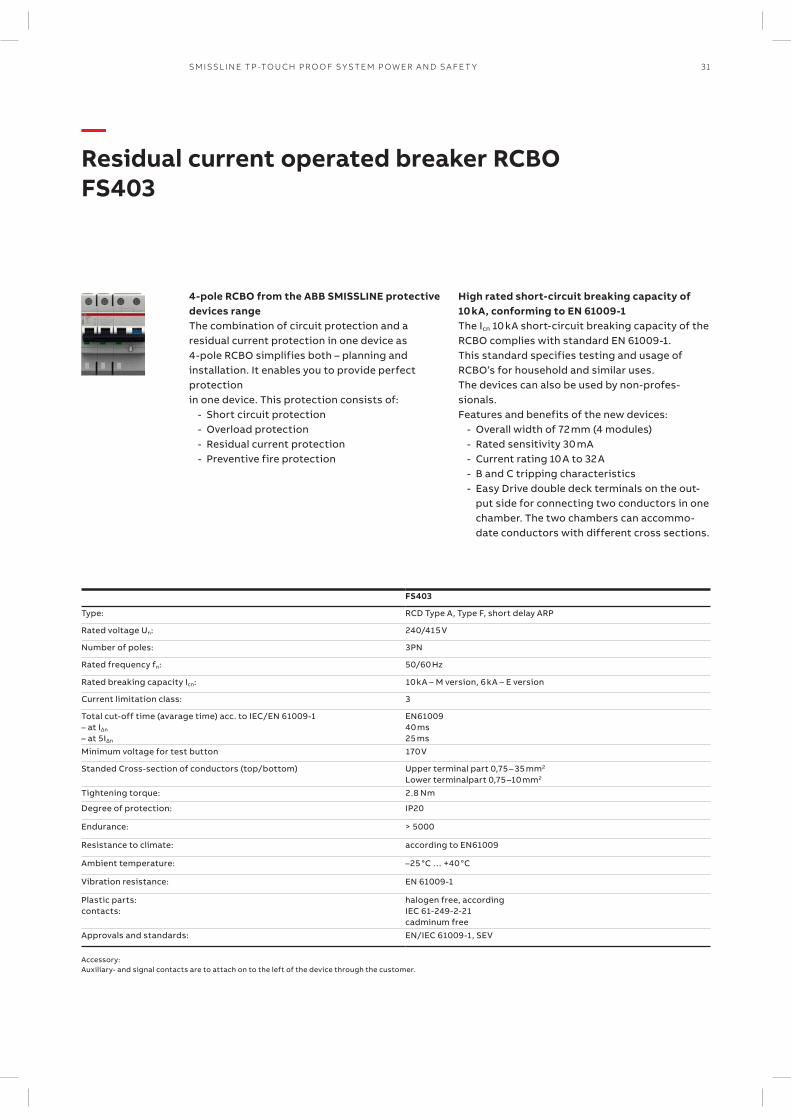
—Residual current operated breaker RCBO FS403
4-pole RCBO from the ABB SMISSLINE protective devices rangeThe combination of circuit protection and a residual current protection in one device as 4-pole RCBO simplifies both – planning and installation. It enables you to provide perfect protection in one device. This protection consists of:
- Short circuit protection - Overload protection - Residual current protection - Preventive fire protection
High rated short-circuit breaking capacity of 10 kA, conforming to EN 61009-1The Icn 10 kA short-circuit breaking capacity of the RCBO complies with standard EN 61009-1.This standard specifies testing and usage of RCBO’s for household and similar uses. The devices can also be used by non-profes-sionals.Features and benefits of the new devices:
- Overall width of 72 mm (4 modules) - Rated sensitivity 30 mA - Current rating 10 A to 32 A - B and C tripping characteristics - Easy Drive double deck terminals on the out-
put side for connecting two conductors in one chamber. The two chambers can accommo-date conductors with different cross sections.
FS403
Type: RCD Type A, Type F, short delay ARP
Rated voltage Un: 240/415 V
Number of poles: 3PN
Rated frequency fn: 50/60 Hz
Rated breaking capacity Icn: 10 kA – M version, 6 kA – E version
Current limitation class: 3
Total cut-off time (avarage time) acc. to IEC/EN 61009-1– at IΔn
– at 5IΔn
EN6100940 ms25 ms
Minimum voltage for test button 170 V
Standed Cross-section of conductors (top/bottom) Upper terminal part 0,75–35 mm2 Lower terminalpart 0,75–10 mm2
Tightening torque: 2.8 Nm
Degree of protection: IP20
Endurance: > 5000
Resistance to climate: according to EN61009
Ambient temperature: –25 °C … +40 °C
Vibration resistance: EN 61009-1
Plastic parts:contacts:
halogen free, according IEC 61-249-2-21cadminum free
Approvals and standards: EN/IEC 61009-1, SEV
Accessory: Auxiliary- and signal contacts are to attach on to the left of the device through the customer.
1/2 3/4 5/6 7/8/N
2/1 4/3 6/5 8/7/N
1/2 3/4 5/6 7/8/N
2/1 4/3 6/5 8/7/N
1/2 3/4 5/6 7/8/N
2/1 4/3 6/5 8/7/N
1/2 3/4 5/6 7/8/N
2/1 4/3 6/5 8/7/N
32 TECH N I C A L C ATA LO G U E SM ISSL I N E TP -TO U CH PR O O F S Y S TEM P OW ER A N D S A FE T Y
—Residual current operated circuit breaker with overcurrent protectionSeries FS403 3LN, Type A
—B, 10 kA according to EN 61009-1
I∆n
[mA]In
[A]Icn
[kA]Type name ABB IT number EAN
number761 227
Pack-agingunit
Module Weightingrams
30 6 10 FS403M-B6/0.03 2CCL564110E0065 143 4434 1 4 41030 10 10 FS403M-B10/0.03 2CCL564110E0105 140 7612 1 4 41030 13 10 FS403M-B13/0.03 2CCL564110E0135 140 7629 1 4 41030 16 10 FS403M-B16/0.03 2CCL564110E0165 140 7636 1 4 41030 20 10 FS403M-B20/0.03 2CCL563110E0205 144 2576 1 4 41030 25 10 FS403M-B25/0.03 2CCL563110E0255 144 2590 1 4 41030 32 10 FS403M-B32/0.03 2CCL563110E0325 144 2613 1 4 410
—C, 6 kA according to EN 61009-1
I∆n
[mA]In
[A]Icn
[kA]Type name ABB IT number EAN
number761 227
Pack-agingunit
Module Weightingrams
30 6 6 FS403E-C6/0.03 2CCL564111E0064 141 9141 1 4 41030 10 6 FS403E-C10/0.03 2CCL564111E0104 143 4489 1 4 41030 13 6 FS403E-C13/0.03 2CCL564111E0134 143 4519 1 4 41030 16 6 FS403E-C16/0.03 2CCL564111E0164 143 4601 1 4 41030 20 6 FS403E-C20/0.03 2CCL564111E0203 140 9609 1 4 41030 25 6 FS403E-C25/0.03 2CCL564111E0254 140 8770 1 4 41030 32 6 FS403E-C32/0.03 2CCL564111E0324 140 8787 1 4 410
—C, 10 kA according to EN 61009-1
I∆n
[mA]In
[A]Icn
[kA]Type name ABB IT number EAN
number761 227
Pack-agingunit
Module Weightingrams
30 6 10 FS403M-C6/0.03 2CCL564110E0064 141 9127 1 4 41030 10 10 FS403M-C10/0.03 2CCL564110E0104 140 7674 1 4 41030 13 10 FS403M-C13/0.03 2CCL564110E0134 140 7681 1 4 41030 16 10 FS403M-C16/0.03 2CCL564110E0164 140 7698 1 4 41030 20 10 FS403M-C20/0.03 2CCL563110E0204 144 2569 1 4 41030 25 10 FS403M-C25/0.03 2CCL563110E0254 144 2583 1 4 41030 32 10 FS403M-C32/0.03 2CCL563110E0324 144 2606 1 4 410
—C, 10 kA according to EN 61009-1
I∆n
[mA]In
[A]Icn
[kA]Type name ABB IT number EAN
number761 227
Pack-agingunit
Module Weightingrams
100 6 6 FS403M-C6/0.1 2CCL564121E0064 142 4527 1 4 410100 10 10 FS403M-C10/0.1 2CCL564121E0104 142 4510 1 4 410100 13 10 FS403M-C13/0.1 2CCL563120E0134 144 2620 1 4 410100 16 10 FS403M-C16/0.1 2CCL564120E0164 142 0109 1 4 410100 20 10 FS403M-C20/0.1 2CCL563120E0204 144 2637 1 4 410100 25 10 FS403M-C25/0.1 2CCL563120E0254 144 2644 1 4 410100 32 10 FS403M-C32/0.1 2CCL563120E0324 144 2651 1 4 410
Ordering details for auxiliary switch and signal contacts on page 41– 45

1/2 3/4 5/6 7/8/N
2/1 4/3 6/5 8/7/N
1/2 3/4 5/6 7/8/N
2/1 4/3 6/5 8/7/N
1/2 3/4 5/6 7/8/N
2/1 4/3 6/5 8/7/N
33SM ISSL I N E TP -TO U CH PR O O F S Y S TEM P OW ER A N D S A FE T Y
—Residual current operated circuit breaker with overcurrent protectionSeries FS403 3LN, Type F short delay
—B 10 kA according to EN 61009-1
I∆n
[mA]In
[A]Icn
[kA]Type name ABB IT number EAN
number761 227
VPE Module Weightingrams
new 30 6 10 2CCL564310E0065 FS403MK-B6/0.03 147 0951 1 4 410new 30 10 10 2CCL564310E0105 FS403MK-B10/0.03 147 0999 1 4 410new 30 13 10 2CCL564310E0135 FS403MK-B13/0.03 147 1033 1 4 410new 30 16 10 2CCL564310E0165 FS403MK-B16/0.03 147 1071 1 4 410new 30 20 10 2CCL563310E0205 FS403MK-B20/0.03 147 0777 1 4 410new 30 25 10 2CCL563310E0255 FS403MK-B25/0.03 147 0814 1 4 410new 30 32 10 2CCL563310E0325 FS403MK-B32/0.03 147 0852 1 4 410
—C, 10 kA according to EN 61009-1
I∆n
[mA]In
[A]Icn
[kA]Type name ABB IT number EAN
number761 227
VPE Module Weightingrams
new 30 6 10 2CCL564310E0064 FS403MK-C6/0.03 147 0937 1 4 410new 30 10 10 2CCL564310E0104 FS403MK-C10/0.03 147 0975 1 4 410new 30 13 10 2CCL564310E0134 FS403MK-C13/0.03 147 1019 1 4 410new 30 16 10 2CCL564310E0164 FS403MK-C16/0.03 147 1057 1 4 410new 30 20 10 2CCL563310E0204 FS403MK-C20/0.03 147 0753 1 4 410new 30 25 10 2CCL563310E0254 FS403MK-C25/0.03 147 0791 1 4 410new 30 32 10 2CCL563310E0324 FS403MK-C32/0.03 147 0838 1 4 410
—C, 10 kA according to EN 61009-1
I∆n
[mA]In
[A]Icn
[kA]Type name ABB IT number EAN
number761 227
VPE Module Weightingrams
new 300 6 10 2CCL564330E0064 FS403MK-C6/0.3 147 1095 1 4 410new 300 10 10 2CCL564330E0104 FS403MK-C10/0.3 147 1118 1 4 410new 300 13 10 2CCL564330E0134 FS403MK-C13/0.3 147 1132 1 4 410new 300 16 10 2CCL564330E0164 FS403MK-C16/0.3 147 1156 1 4 410new 300 20 10 2CCL563330E0204 FS403MK-C20/0.3 147 0876 1 4 410new 300 25 10 2CCL563330E0254 FS403MK-C25/0.3 147 0890 1 4 410new 300 32 10 2CCL563330E0324 FS403MK-C32/0.3 147 0913 1 4 410
34 TECH N I C A L C ATA LO G U E SM ISSL I N E TP -TO U CH PR O O F S Y S TEM P OW ER A N D S A FE T Y
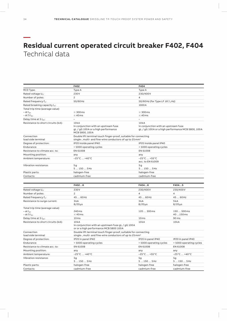
—Residual current operated circuit breaker F402, F404Technical data
F402 F404RCD Type: Type A Type ARated voltage Un: 230 V 230/400 VNumber of poles: 2 4Rated frequency fn: 50/60 Hz 50/60 Hz (for Type LF 162/3 Hz)Rated breaking capacity Im: 1000 ATotal trip time (average value)– at I∆n
– at 5 I∆n
300 ms 40 ms
300 ms 40 ms
Delay time at 5 I∆n: – –Resistance to short circuits (kA): 10 kA
in conjunction with an upstream fusegL / gG 100 A or a high performance MCB S800, 100 A
10 kAin conjunction with an upstream fusegL / gG 100 A or a high performance MCB S800, 100 A
Connection load side terminal
Double lift terminal touch finger-proof, suitable for connectingsingle-, multi- and fine-wire conductors of up to 25 mm2
Degree of protection: IP20 inside panel IP40 IP20 inside panel IP40Endurance: > 5000 operating cycles > 5000 operating cyclesResistance to climate acc. to: EN 61008 EN 61008Mounting position: any anyAmbient temperature: –25°C … +40°C –25°C … +55°C
acc. to EN 61009Vibration resistance: 5 g
5 … 150 … 5 Hz5 g5 … 150 … 5 Hz
Plastic parts: halogen-free halogen-freeContacts: cadmium-free cadmium-free
F402…K F404…K F404…S
Rated voltage Un: 230 V 230/400 V 230/400 VNumber of poles: 2 4 4Rated frequency fn: 45 … 60 Hz 45 … 60 Hz 45 … 60 HzResistance to surge current: 3 kA
8/20 µs3 kA8/20 µs
5 kA8/20 µs
Total trip time (average value)– at I∆n
– at 5 I∆n
240 ms 40 ms
120 … 300 ms 150 … 500 ms40 …150 ms
Delay time at 5 I∆n: 10 ms 10 ms 90 msResistance to short circuits (kA): 10 kA
in conjunction with an upstream fuse gL / gG 100 Aor or a high performance MCB S800 100 A
10 kA 10 kA
Connection load side terminal
Double lift terminal touch finger-proof, suitable for connectingsingle-, multi- and fine-wire conductors of up to 25 mm2
Degree of protection: IP20 in panel IP40 IP20 in panel IP40 IP20 in panel IP40Endurance: > 5000 operating cycles > 5000 operating cycles > 5000 operating cyclesResistance to climate acc. to: EN 61008 EN 61008 EN 61008Mounting position: any any anyAmbient temperature: –25°C … +40°C –25°C … +55°C –25°C … +40°CVibration resistance: 5g
5 … 150 … 5 Hz5g5 … 150 … 5 Hz
5g5 … 150 … 5 Hz
Plastic parts: halogen-free halogen-free halogen-freeContacts: cadmium-free cadmium-free cadmium-free
1/2 3/4
2/1 4/3
5/6 7/8/N
6/5 8/7/N
35SM ISSL I N E TP -TO U CH PR O O F S Y S TEM P OW ER A N D S A FE T Y
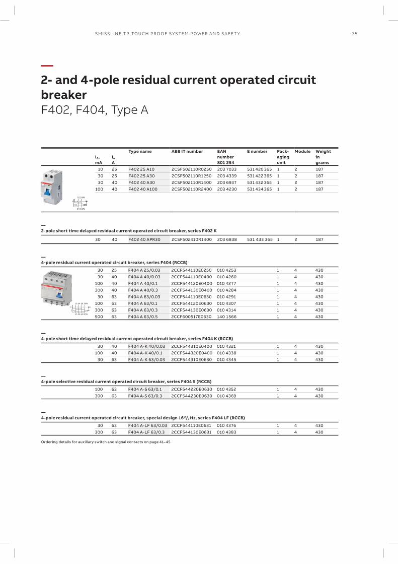
—2- and 4-pole residual current operated circuit breakerF402, F404, Type A
IΔn
mAIn A
Type name ABB IT number EANnumber801 254
E number
Pack- aging unit
Module Weight in grams
10 25 F402 25 A10 2CSF502110R0250 203 7033 531 420 365 1 2 187 30 25 F402 25 A30 2CSF502110R1250 203 4339 531 422 365 1 2 187 30 40 F402 40 A30 2CSF502110R1400 203 6937 531 432 365 1 2 187100 40 F402 40 A100 2CSF502110R2400 203 4230 531 434 365 1 2 187
—2-pole short time delayed residual current operated circuit breaker, series F402 K
30 40 F402 40 APR30 2CSF502410R1400 203 6838 531 433 365 1 2 187
—4-pole residual current operated circuit breaker, series F404 (RCCB)
30 25 F404 A 25/0.03 2CCF544110E0250 010 4253 1 4 430 30 40 F404 A 40/0.03 2CCF544110E0400 010 4260 1 4 430100 40 F404 A 40/0.1 2CCF544120E0400 010 4277 1 4 430300 40 F404 A 40/0.3 2CCF544130E0400 010 4284 1 4 430 30 63 F404 A 63/0.03 2CCF544110E0630 010 4291 1 4 430100 63 F404 A 63/0.1 2CCF544120E0630 010 4307 1 4 430300 63 F404 A 63/0.3 2CCF544130E0630 010 4314 1 4 430500 63 F404 A 63/0.5 2CCF600517E0630 140 1566 1 4 430
—4-pole short time delayed residual current operated circuit breaker, series F404 K (RCCB)
30 40 F404 A-K 40/0.03 2CCF544310E0400 010 4321 1 4 430100 40 F404 A-K 40/0.1 2CCF544320E0400 010 4338 1 4 430 30 63 F404 A-K 63/0.03 2CCF544310E0630 010 4345 1 4 430
—4-pole selective residual current operated circuit breaker, series F404 S (RCCB)
100 63 F404 A-S 63/0.1 2CCF544220E0630 010 4352 1 4 430300 63 F404 A-S 63/0.3 2CCF544230E0630 010 4369 1 4 430
—4-pole residual current operated circuit breaker, special design 162/3 Hz, series F404 LF (RCCB)
30 63 F404 A-LF 63/0.03 2CCF544110E0631 010 4376 1 4 430300 63 F404 A-LF 63/0.3 2CCF544130E0631 010 4383 1 4 430
Ordering details for auxiliary switch and signal contacts on page 41– 45
36 TECH N I C A L C ATA LO G U E SM ISSL I N E TP -TO U CH PR O O F S Y S TEM P OW ER A N D S A FE T Y
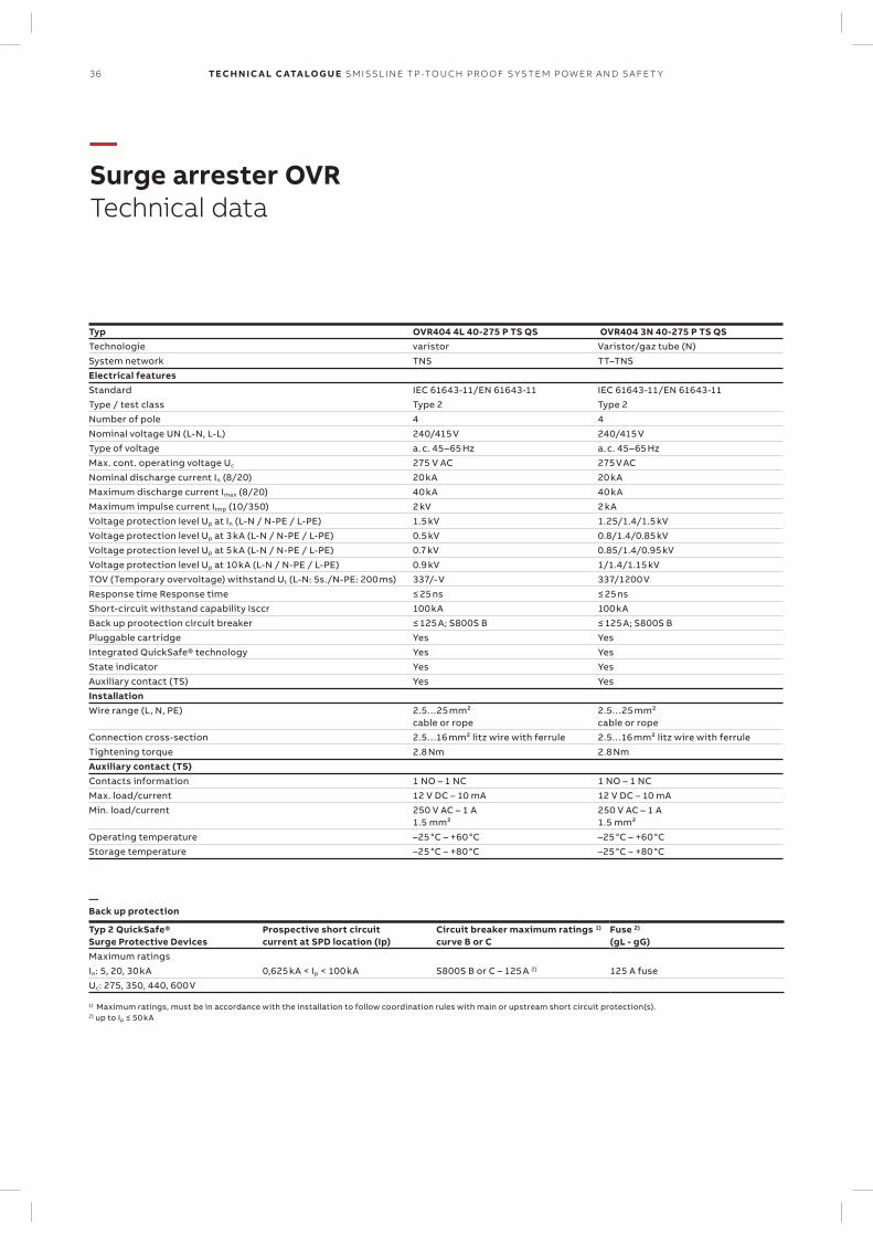
—Surge arrester OVRTechnical data
Typ OVR404 4L 40-275 P TS QS OVR404 3N 40-275 P TS QSTechnologie varistor Varistor/gaz tube (N)System network TNS TT–TNSElectrical featuresStandard IEC 61643-11/EN 61643-11 IEC 61643-11/EN 61643-11Type / test class Type 2 Type 2Number of pole 4 4Nominal voltage UN (L-N, L-L) 240/415 V 240/415 VType of voltage a. c. 45–65 Hz a. c. 45–65 HzMax. cont. operating voltage Uc 275 V AC 275 V ACNominal discharge current In (8/20) 20 kA 20 kA Maximum discharge current Imax (8/20) 40 kA 40 kAMaximum impulse current Iimp (10/350) 2 kV 2 kAVoltage protection level Up at In (L-N / N-PE / L-PE) 1.5 kV 1.25/1.4/1.5 kV Voltage protection level Up at 3 kA (L-N / N-PE / L-PE) 0.5 kV 0.8/1.4/0.85 kVVoltage protection level Up at 5 kA (L-N / N-PE / L-PE) 0.7 kV 0.85/1.4/0.95 kV Voltage protection level Up at 10 kA (L-N / N-PE / L-PE) 0.9 kV 1/1.4/1.15 kV TOV (Temporary overvoltage) withstand Ut (L-N: 5s./N-PE: 200 ms) 337/- V 337/1200 V Response time Response time ≤ 25 ns ≤ 25 ns Short-circuit withstand capability Isccr 100 kA 100 kABack up prootection circuit breaker ≤ 125 A; S800S B ≤ 125 A; S800S BPluggable cartridge Yes YesIntegrated QuickSafe® technology Yes YesState indicator Yes YesAuxiliary contact (TS) Yes YesInstallationWire range (L, N, PE) 2.5…25 mm²
cable or rope2.5…25 mm² cable or rope
Connection cross-section 2.5…16 mm² litz wire with ferrule 2.5…16 mm² litz wire with ferrule Tightening torque 2.8 Nm 2.8 Nm Auxiliary contact (TS)Contacts information 1 NO – 1 NC 1 NO – 1 NCMax. load/current 12 V DC – 10 mA 12 V DC – 10 mAMin. load/current 250 V AC – 1 A
1.5 mm²250 V AC – 1 A1.5 mm²
Operating temperature –25 °C – +60 °C –25 °C – +60 °CStorage temperature –25 °C – +80 °C –25 °C – +80 °C
—Back up protection
Typ 2 QuickSafe® Surge Protective Devices
Prospective short circuit current at SPD location (Ip)
Circuit breaker maximum ratings 1)
curve B or CFuse 2)
(gL - gG)Maximum ratingsIn: 5, 20, 30 kA 0,625 kA < Ip < 100 kA S800S B or C – 125 A 2) 125 A fuseUc: 275, 350, 440, 600 V
1) Maximum ratings, must be in accordance with the installation to follow coordination rules with main or upstream short circuit protection(s). 2) up to Ip ≤ 50 kA
1/2 3/4
2/1 4/3
5/6 7/8/N
6/5 8/7/N
OVR404 4L
OVR404 3LN
37SM ISSL I N E TP -TO U CH PR O O F S Y S TEM P OW ER A N D S A FE T Y
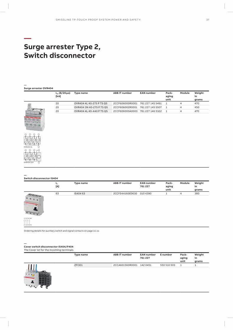
—Surge arrester Type 2, Switch disconnector
—Surge arrester OVR404
Isn (8/20 µs)[kA]
Type name ABB IT number EAN number Pack-agingunit
Module Weightingrams
20 OVR404 4L 40-275 P TS QS 2CCF606000R0001 761 227 145 5491 1 4 47020 OVR404 3N 40-275 P TS QS 2CCF606002R0001 761 227 145 5507 1 4 45020 OVR404 4L 40-440 P TS QS 2CCF606000A0003 761 227 146 5322 1 4 470
—Switch disconnector IS404
In
[A]Type name ABB IT number EAN number
761 227Pack-agingunit
Module Weightingrams
63 IS404 63 2CCF544160E0630 010 4390 1 4 380
Ordering details for auxiliary switch and signal contacts on page xx–xx
—Cover switch disconnector IS404/F404The Cover ist for the Incoming terminals
Type name ABB IT number EAN number761 227
E number Pack-agingunit
Weightingrams
ZFI301 2CCA601560R0001 142 0451 550 510 503 1 1
I >
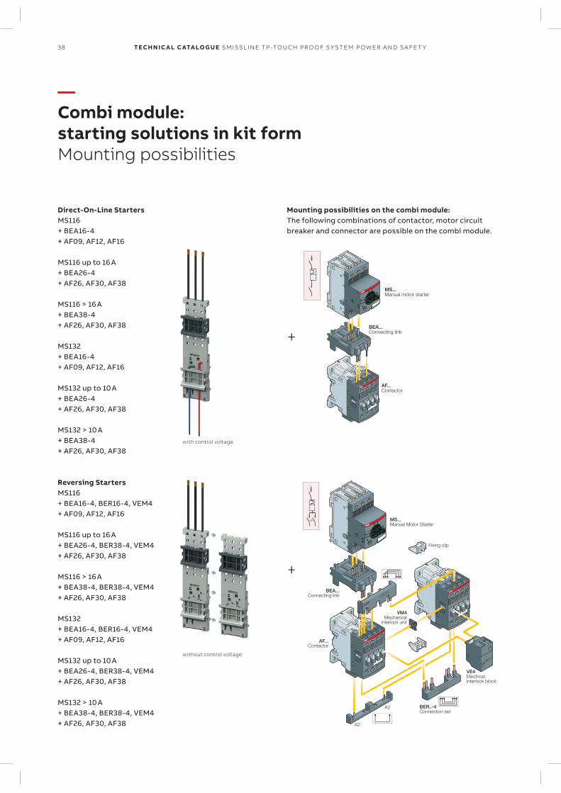
MS... Manual motor starter
BEA... Connecting link
AF... Contactor
VE4 Electrical interlock block
BEA... Connecting link
MS... Manual Motor Starter
BER..-4 Connection set
AF... Contactor
A2
A2
Fixing clip
I >
VM4 Mechanical
interlock unit
+
+
with control voltage
without control voltage
38 TECH N I C A L C ATA LO G U E SM ISSL I N E TP -TO U CH PR O O F S Y S TEM P OW ER A N D S A FE T Y
—Combi module: starting solutions in kit formMounting possibilities
Mounting possibilities on the combi module:The following combinations of contactor, motor circuit breaker and connector are possible on the combi module.
Direct-On-Line StartersMS116+ BEA16-4+ AF09, AF12, AF16
MS116 up to 16 A+ BEA26-4+ AF26, AF30, AF38
MS116 > 16 A+ BEA38-4+ AF26, AF30, AF38
MS132+ BEA16-4+ AF09, AF12, AF16
MS132 up to 10 A+ BEA26-4+ AF26, AF30, AF38
MS132 > 10 A+ BEA38-4+ AF26, AF30, AF38
Reversing StartersMS116+ BEA16-4, BER16-4, VEM4+ AF09, AF12, AF16
MS116 up to 16 A+ BEA26-4, BER38-4, VEM4+ AF26, AF30, AF38
MS116 > 16 A+ BEA38-4, BER38-4, VEM4+ AF26, AF30, AF38
MS132+ BEA16-4, BER16-4, VEM4+ AF09, AF12, AF16
MS132 up to 10 A+ BEA26-4, BER38-4, VEM4+ AF26, AF30, AF38
MS132 > 10 A+ BEA38-4, BER38-4, VEM4+ AF26, AF30, AF38
39SM ISSL I N E TP -TO U CH PR O O F S Y S TEM P OW ER A N D S A FE T Y
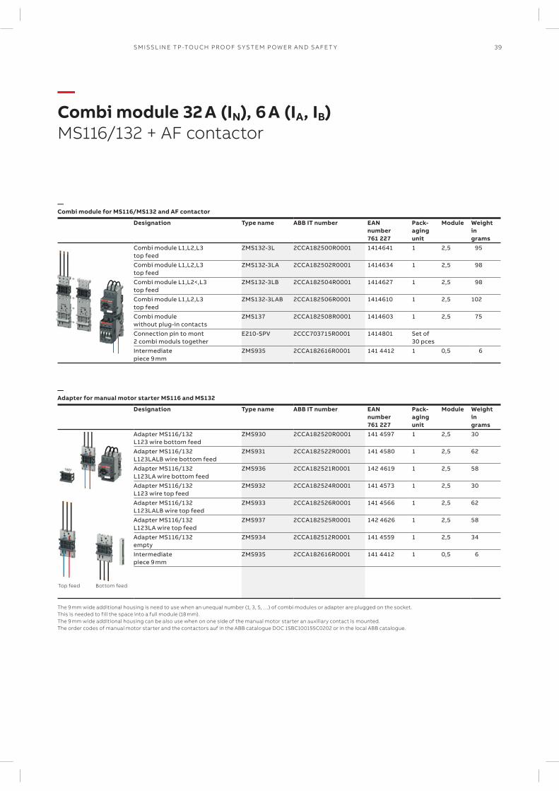
—Combi module 32 A (IN), 6 A (IA, IB)MS116/132 + AF contactor
—Combi module for MS116/MS132 and AF contactor
Designation Type name ABB IT number EANnumber761 227
Pack-agingunit
Module Weightingrams
Combi module L1,L2,L3 top feed
ZMS132-3L 2CCA182500R0001 1414641 1 2,5 95
Combi module L1,L2,L3 top feed
ZMS132-3LA 2CCA182502R0001 1414634 1 2,5 98
Combi module L1,L2<,L3 top feed
ZMS132-3LB 2CCA182504R0001 1414627 1 2,5 98
Combi module L1,L2,L3 top feed
ZMS132-3LAB 2CCA182506R0001 1414610 1 2,5 102
Combi module without plug-in contacts
ZMS137 2CCA182508R0001 1414603 1 2,5 75
Connection pin to mont 2 combi moduls together
E210-SPV 2CCC703715R0001 1414801 Set of 30 pces
Intermediate piece 9 mm
ZMS935 2CCA182616R0001 141 4412 1 0,5 6
—Adapter for manual motor starter MS116 and MS132
Designation Type name ABB IT number EANnumber761 227
Pack-agingunit
Module Weightingrams
Adapter MS116/132 L123 wire bottom feed
ZMS930 2CCA182520R0001 141 4597 1 2,5 30
Adapter MS116/132 L123LALB wire bottom feed
ZMS931 2CCA182522R0001 141 4580 1 2,5 62
Adapter MS116/132 L123LA wire bottom feed
ZMS936 2CCA182521R0001 142 4619 1 2,5 58
Adapter MS116/132 L123 wire top feed
ZMS932 2CCA182524R0001 141 4573 1 2,5 30
Adapter MS116/132 L123LALB wire top feed
ZMS933 2CCA182526R0001 141 4566 1 2,5 62
Adapter MS116/132 L123LA wire top feed
ZMS937 2CCA182525R0001 142 4626 1 2,5 58
Adapter MS116/132 empty
ZMS934 2CCA182512R0001 141 4559 1 2,5 34
Intermediate piece 9 mm
ZMS935 2CCA182616R0001 141 4412 1 0,5 6
The 9 mm wide additional housing is need to use when an unequal number (1, 3, 5, …) of combi modules or adapter are plugged on the socket. This is needed to fill the space into a full module (18 mm). The 9 mm wide additional housing can be also use when on one side of the manual motor starter an auxiliary contact is mounted. The order codes of manual motor starter and the contactors auf in the ABB catalogue DOC 1SBC100155C0202 or in the local ABB catalogue.
Top feed Bottom feed
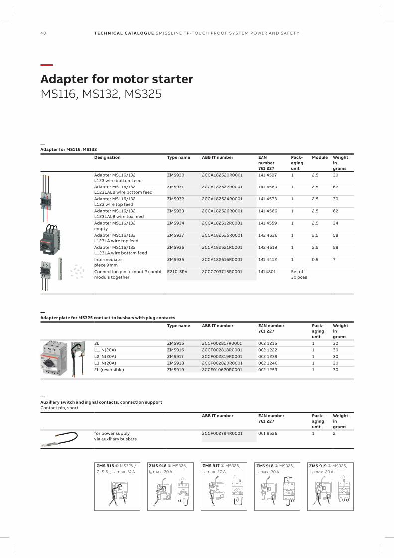
ZMS 917 ⑤ MS325, In max. 20 A
ZMS 916 ⑤ MS325, In max. 20 A
ZMS 915 ⑤ MS325 / ZLS 5.., In max. 32 A
ZMS 918 ⑤ MS325, In max. 20 A
ZMS 919 ⑤ MS325, In max. 20 A
40 TECH N I C A L C ATA LO G U E SM ISSL I N E TP -TO U CH PR O O F S Y S TEM P OW ER A N D S A FE T Y
—Adapter for motor starterMS116, MS132, MS325
—Adapter for MS116, MS132
Designation Type name ABB IT number EANnumber761 227
Pack-agingunit
Module Weightingrams
Adapter MS116/132L123 wire bottom feed
ZMS930 2CCA182520R0001 141 4597 1 2,5 30
Adapter MS116/132L123LALB wire bottom feed
ZMS931 2CCA182522R0001 141 4580 1 2,5 62
Adapter MS116/132L123 wire top feed
ZMS932 2CCA182524R0001 141 4573 1 2,5 30
Adapter MS116/132L123LALB wire top feed
ZMS933 2CCA182526R0001 141 4566 1 2,5 62
Adapter MS116/132empty
ZMS934 2CCA182512R0001 141 4559 1 2,5 34
Adapter MS116/132L123LA wire top feed
ZMS937 2CCA182525R0001 142 4626 1 2,5 58
Adapter MS116/132L123LA wire bottom feed
ZMS936 2CCA182521R0001 142 4619 1 2,5 58
Intermediatepiece 9 mm
ZMS935 2CCA182616R0001 141 4412 1 0,5 7
Connection pin to mont 2 combimoduls together
E210-SPV 2CCC703715R0001 1414801 Set of 30 pces
—Adapter plate for MS325 contact to busbars with plug contacts
Type name ABB IT number EAN number761 227
Pack-agingunit
Weightingrams
3L ZMS915 2CCF002817R0001 002 1215 1 30L1, N(20A) ZMS916 2CCF002818R0001 002 1222 1 30L2, N(20A) ZMS917 2CCF002819R0001 002 1239 1 30L3, N(20A) ZMS918 2CCF002820R0001 002 1246 1 30 2L (reversible) ZMS919 2CCF010620R0001 002 1253 1 30
—Auxiliary switch and signal contacts, connection supportContact pin, short
ABB IT number EAN number761 227
Pack-agingunit
Weightingrams
for power supplyvia auxiliary busbars
2CCF002794R0001 001 9526 1 2
13 21
14 22
13 21
14 22
13 21
14 22
97 05
98 06
97
98
97
98
41SM ISSL I N E TP -TO U CH PR O O F S Y S TEM P OW ER A N D S A FE T Y
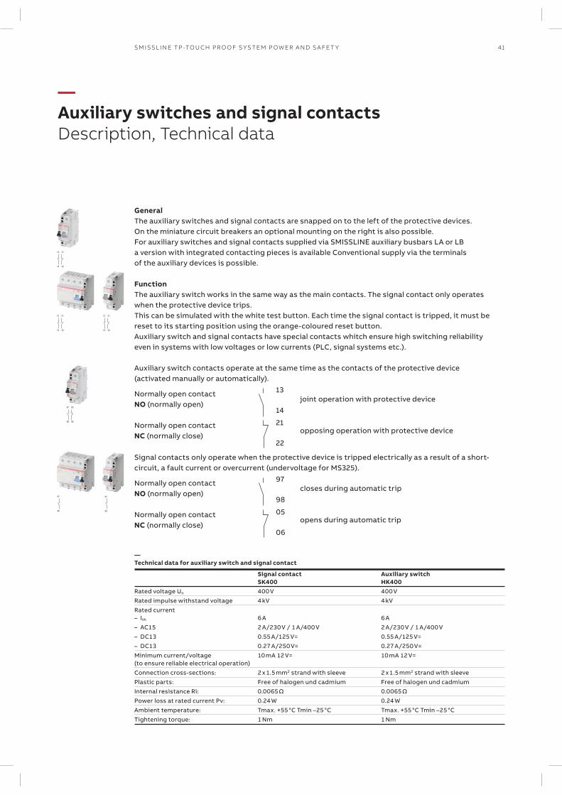
—Auxiliary switches and signal contactsDescription, Technical data
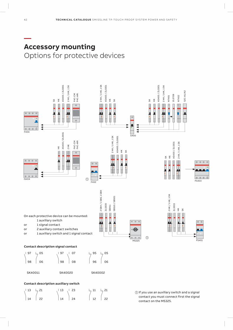
GeneralThe auxiliary switches and signal contacts are snapped on to the left of the protective devices. On the miniature circuit breakers an optional mounting on the right is also possible. For auxiliary switches and signal contacts supplied via SMISSLINE auxiliary busbars LA or LB a version with integrated contacting pieces is available Conventional supply via the terminals of the auxiliary devices is possible.
FunctionThe auxiliary switch works in the same way as the main contacts. The signal contact only operates when the protective device trips. This can be simulated with the white test button. Each time the signal contact is tripped, it must be reset to its starting position using the orange-coloured reset button. Auxiliary switch and signal contacts have special contacts whitch ensure high switching reliability even in systems with low voltages or low currents (PLC, signal systems etc.). Auxiliary switch contacts operate at the same time as the contacts of the protective device (activated manually or automatically).
Normally open contact
13
14joint operation with protective device
NO (normally open)
Normally open contact 21
22
opposing operation with protective deviceNC (normally close)
Signal contacts only operate when the protective device is tripped electrically as a result of a short- circuit, a fault current or overcurrent (undervoltage for MS325).
Normally open contact
97
98closes during automatic trip
NO (normally open)
Normally open contact 05
06
opens during automatic tripNC (normally close)
—Technical data for auxiliary switch and signal contact
Signal contactSK400
Auxiliary switchHK400
Rated voltage Un 400 V 400 VRated impulse withstand voltage 4 kV 4 kVRated current– Ith 6 A 6 A– AC15 2 A/230 V / 1 A/400 V 2 A/230 V / 1 A/400 V– DC13 0.55 A/125 V= 0.55 A/125 V=– DC13 0.27 A/250 V= 0.27 A/250 V=Minimum current/voltage(to ensure reliable electrical operation)
10 mA 12 V= 10 mA 12 V=
Connection cross-sections: 2 x 1.5 mm2 strand with sleeve 2 x 1.5 mm2 strand with sleevePlastic parts: Free of halogen und cadmium Free of halogen und cadmiumInternal resistance Ri: 0.0065 Ω 0.0065 ΩPower loss at rated current Pv: 0.24 W 0.24 WAmbient temperature: Tmax. +55 °C Tmin –25 °C Tmax. +55 °C Tmin –25 °CTightening torque: 1 Nm 1 Nm
97
98
13
14
97
98
13
14
95
96
11
12
05
06
21
22
07
08
23
24
05
06
21
22
L2
S400
2 H
K /
1H
K, 1
SK
SK
HK
AS
40
0 /
ZLS
931
2 H
K /
1 H
K, 1
SK
SK
HK
AS
40
0 /
ZLS
931
NT4
01
N
T
IS404
N
T
F404
2 H
K /
1H
K, 1
SK
F4C
-CM
F4
C-A
RI
F4C
-CM
F4
C-A
RI
SK
HK
AS
40
0 /
ZLS
931
2 H
K
HK
AS
40
0 /
ZLS
931
ZLS
728
NT4
02
SB
S10
/ S
BS
01
SB
H11
ZLS
930
2 S
BH
/ 1
SB
S, 1
SB
H
0
T12
T16
T14
1L1
5L3
3L2
MS325
N
T
FS403
SK
2 H
K /
1 H
K, 1
SK
AS
40
0 /
ZLS
931
HK
S2C
-A1/
A2
L2
T
F402
SK
HK
AS
40
0 /
ZLS
931
2 H
K /
1 H
K, 1
SK
L2
T
FS401
SK
HK
ZLS
933
2 H
K /
1 H
K, 1
SK
On each protective device can be mounted: 1 auxiliary switchor 1 signal contactor 2 auxiliary contact switchesor 1 auxiliary switch and 1 signal contact
If you use an auxiliary switch and a signal contact you must connect first the signal contact on the MS325.
Contact description signal contact
SK40011 SK40020 SK40002
Contact description auxiliary switch
42 TECH N I C A L C ATA LO G U E SM ISSL I N E TP -TO U CH PR O O F S Y S TEM P OW ER A N D S A FE T Y
—Accessory mountingOptions for protective devices
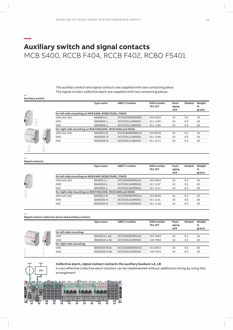
13 21
14 22
13 21
14 22
13 21
14 22
97 05
98 06
97
98
97
98
43SM ISSL I N E TP -TO U CH PR O O F S Y S TEM P OW ER A N D S A FE T Y
—Auxiliary switch and signal contactsMCB S400, RCCB F404, RCCB F402, RCBO FS401
The auxiliary switch and signal contacts are supplied with one contacting piece. The signal contact collective alarm are supplied with two contacting pieces.
—Auxiliary switch
Type name ABB IT number EAN number761 227
Pack-agingunit
Module Weightingrams
for left side mounting on MCB S400, RCBO FS401, FS4031NO and 1NC HK40011-L 2CCS500900R0081 010 0910 10 0.5 452NO HK40020-L 2CCF201112R0001 011 1183 10 0.5 402NC HK40002-L 2CCF201114R0001 011 1190 10 0.5 40for right side mounting on RCB F404/402, MCB S400 and IS4041NO and 1NC HK40011-R 2CCS500900R0214 010 8619 10 0.5 452NO HK40020-R 2CCF201113R0001 011 1206 10 0.5 402NC HK40002-R 2CCF201115R0001 011 1213 10 0.5 40
—Signal contacts
Type name ABB IT number EAN number761 227
Pack-agingunit
Module Weightingrams
for left side mounting on MCB S400, RCBO FS401, FS4031NO and 1NC SK40011-L 2CCS500900R0101 010 0934 10 0.5 452NO SK40020-L 2CCF201162R0001 011 1107 10 0.5 402NC SK40002-L 2CCF201164R0001 011 1114 10 0.5 40for right side mounting on RCB F404/402, MCB S400 and IS4041NO and 1NC SK40011-R 2CCS500900R0215 010 8626 10 0.5 452NO SK40020-R 2CCF201163R0001 011 1121 10 0.5 402NC SK40002-R 2CCF201165R0001 011 1138 10 0.5 40
—Signal contact collective alarm and auxiliary contact
Type name ABB IT number EAN number761 227
Pack-agingunit
Module Weightingrams
for left side mounting1NO SK40010-L SA 2CCS500900R0141 010 7964 10 0.5 451NO HK40010-L SA 2CCF201212R0001 140 7902 10 0.5 45for right side mounting1NO SK40010-R SA 2CCS500900R0216 010 8633 10 0.5 451NO HK40010-R SA 2CCF201213R0001 140 7919 10 0.5 45
Collective alarm, signal contact contacts the auxiliary busbars LA, LBA cost-effective collective alarm solution can be implemented without additional wiring by using this arrangement.
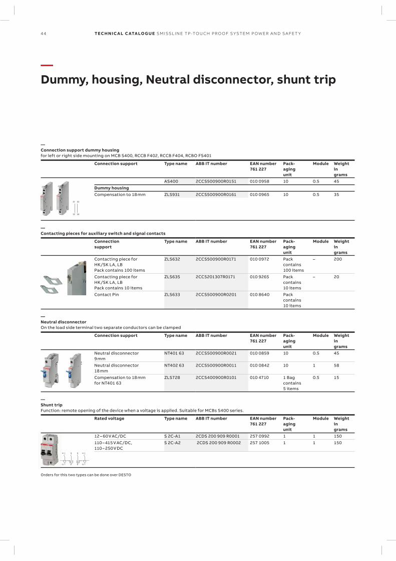
C1 C3
C2 C4
1
2
C1
C2
1
2
C1
C2
44 TECH N I C A L C ATA LO G U E SM ISSL I N E TP -TO U CH PR O O F S Y S TEM P OW ER A N D S A FE T Y
—Dummy, housing, Neutral disconnector, shunt trip
—Connection support dummy housingfor left or right side mounting on MCB S400, RCCB F402, RCCB F404, RCBO FS401
Connection support Type name ABB IT number EAN number761 227
Pack-agingunit
Module Weightingrams
AS400 2CCS500900R0151 010 0958 10 0.5 45Dummy housingCompensation to 18 mm ZLS931 2CCS500900R0161 010 0965 10 0.5 35
—Contacting pieces for auxiliary switch and signal contacts
Connectionsupport
Type name ABB IT number EAN number761 227
Pack-agingunit
Module Weightingrams
Contacting piece for HK/SK LA, LBPack contains 100 items
ZLS632 2CCS500900R0171 010 0972 Packcontains100 items
– 200
Contacting piece forHK/SK LA, LBPack contains 10 items
ZLS635 2CC5201307R0171 010 9265 Packcontains10 items
– 20
Contact Pin ZLS633 2CCS500900R0201 010 8640 Pack contains 10 items
—Neutral disconnectorOn the load side terminal two separate conductors can be clamped
Connection support Type name ABB IT number EAN number761 227
Pack-agingunit
Module Weightingrams
Neutral disconnector9 mm
NT401 63 2CCS500900R0021 010 0859 10 0.5 45
Neutral disconnector18 mm
NT402 63 2CCS500900R0011 010 0842 10 1 58
Compensation to 18 mm for NT401 63
ZLS728 2CCS400900R0101 010 4710 1 Bag contains 5 items
0.5 15
—Shunt tripFunction: remote opening of the device when a voltage is applied. Suitable for MCBs S400 series.
Rated voltage Type name ABB IT number EAN number761 227
Pack-agingunit
Module Weightingrams
12 – 60 V AC/DC S 2C-A1 2CDS 200 909 R0001 257 0992 1 1 150110 – 415 V AC/DC, 110 – 250 V DC
S 2C-A2 2CDS 200 909 R0002 257 1005 1 1 150
Orders for this two types can be done over DESTO
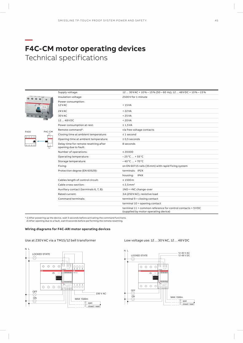
MAX 1500m
6 7 8 9 10 11
1 2 3 4 5
LOCKED
AUX
LOCKED STATE
N L
closed / resetopen
OFF
ON
12-30 V AC12-48 V DC
6 7 8 9 10 11
1 2 3 4 5
LOCKED
AUX
TM15/2
5 6 7 8
1 2 3 4
LOCKED STATE
N L
closed / resetopen
OFF
ON MAX 1500m
230 V AC
F400 F4C-CM
45SM ISSL I N E TP -TO U CH PR O O F S Y S TEM P OW ER A N D S A FE T Y
—F4C-CM motor operating devicesTechnical specifications
Supply voltage: 12 ... 30 V AC + 10 % – 15 % (50 – 60 Hz); 12 ... 48 V DC + 10 % – 15 %
Insulation voltage: 2500 V for 1 minute
Power consumption:12 V AC < 15 VA
24 V AC < 22 VA
30 V AC < 25 VA
12 ... 48 V DC < 20 VA
Power consumption at rest: ≤ 1,5 VA
Remote command*: via free voltage contacts
Closing time at ambient temperature: ≤ 1 second
Opening time at ambient temperature: ≤ 0,5 seconds
Delay time for remote resetting after opening due to fault:
8 seconds
Number of operations: ≤ 20 000
Operating temperature: – 25 °C … + 55 °C
Storage temperature: – 40 °C … + 70 °C
Fixing: on EN 60715 rails (35 mm) with rapid fixing system
Protection degree (EN 60529): terminals: IP2X
housing: IP4X
Cables length of control circuit: ≤ 1500 m
Cable cross-section: ≤ 2,5 mm2
Auxiliary contact (terminals 6, 7, 8): 1NO + +NC change-over
Rated current: 3 A (250 V AC), resistive load
Command terminals: terminal 9 = closing contact
terminal 10 = opening contact
terminal 11 = common reference for control contacts + 5 V DC (supplied by motor operating device)
* 1) After powering up the device, wait 5 seconds before activating the command functions.2) After opening due to a fault, wait 8 seconds before performing the remote resetting.
Wiring diagrams for F4C-ARI motor operating devices
Use at 230 V AC via a TM15/12 bell transformer Low voltage use: 12 … 30 V AC, 12 … 48 V DC
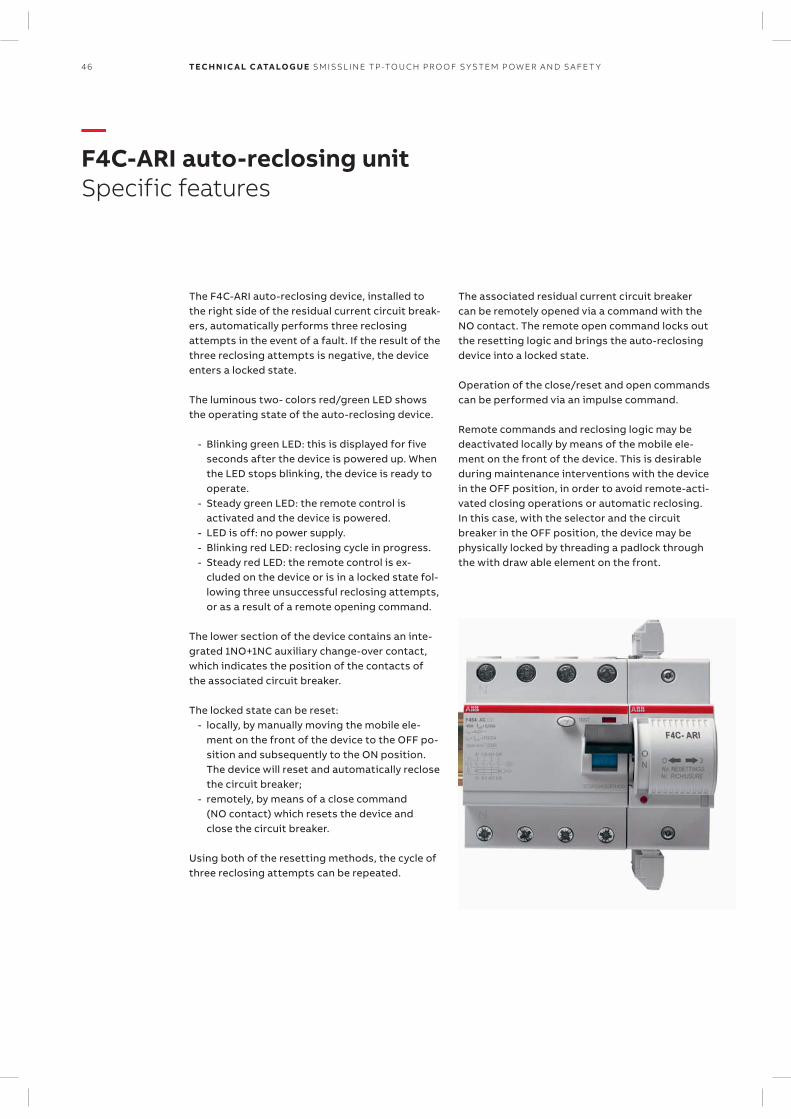
46 TECH N I C A L C ATA LO G U E SM ISSL I N E TP -TO U CH PR O O F S Y S TEM P OW ER A N D S A FE T Y
—F4C-ARI auto-reclosing unitSpecific features
The F4C-ARI auto-reclosing device, installed to the right side of the residual current circuit break-ers, automatically performs three reclosing attempts in the event of a fault. If the result of the three reclosing attempts is negative, the device enters a locked state.
The luminous two- colors red/green LED shows the operating state of the auto-reclosing device.
- Blinking green LED: this is displayed for five seconds after the device is powered up. When the LED stops blinking, the device is ready to operate.
- Steady green LED: the remote control is activated and the device is powered.
- LED is off: no power supply. - Blinking red LED: reclosing cycle in progress. - Steady red LED: the remote control is ex-
cluded on the device or is in a locked state fol-lowing three unsuccessful reclosing attempts, or as a result of a remote opening command.
The lower section of the device contains an inte-grated 1NO+1NC auxiliary change-over contact, which indicates the position of the contacts of the associated circuit breaker.
The locked state can be reset: - locally, by manually moving the mobile ele-
ment on the front of the device to the OFF po-sition and subsequently to the ON position. The device will reset and automatically reclose the circuit breaker;
- remotely, by means of a close command (NO contact) which resets the device and close the circuit breaker.
Using both of the resetting methods, the cycle of three re closing attempts can be repeated.
The associated residual current circuit breaker can be remotely opened via a command with the NO contact. The remote open command locks out the resetting logic and brings the auto-reclosing device into a locked state.
Operation of the close/reset and open commands can be performed via an impulse command.
Remote commands and reclosing logic may be deactivated locally by means of the mobile ele-ment on the front of the device. This is desirable during maintenance interventions with the device in the OFF position, in order to avoid remote-acti-vated closing operations or automatic reclosing. In this case, with the selector and the circuit breaker in the OFF position, the device may be physically locked by threading a padlock through the with draw able element on the front.
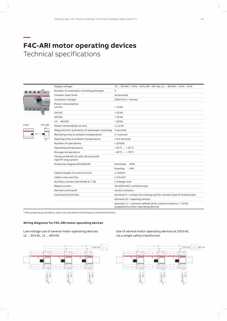
6 7 8 9 10 11
AUX
1 2 3 4 5
LOCKED
6 7 8 9 10 11
AUX
1 2 3 4 5
LOCKED
6 7 8 9 10 11
AUX
1 2 3 4 5
LOCKED
closed / reset
open
1 2 n ...
12-48 V DC
closed / reset
open
closed / reset
open
6 7 8 9 10 11
AUX
1 2 3 4 5
LOCKED
6 7 8 9 10 11
AUX
1 2 3 4 5
LOCKED
6 7 8 9 10 11
AUX
1 2 3 4 5
LOCKED
closed / reset
open
1 2 n ...
12-30 V AC 230 V AC
closed / reset
open
closed / reset
open
F400 F4C-ARI
47SM ISSL I N E TP -TO U CH PR O O F S Y S TEM P OW ER A N D S A FE T Y
—F4C-ARI motor operating devicesTechnical specifications
Supply voltage: 12 ... 30 V AC + 10 % – 15 % (50 – 60 Hz); 12 ... 48 V DC + 10 % – 15 %
Number of automatic reclosing attempts: 3
Counter reset time: 16 seconds
Insulation voltage: 2500 V for 1 minute
Power consumption:12 V AC < 15 VA
24 V AC < 22 VA
30 V AC < 25 VA
12 ... 48 V DC < 20 VA
Power consumption at rest: ≤ 1,5 VA
Delay time for activation of automatic reclosing: 3 seconds
Reclosing time at ambient temperature: ≤ 1 second
Opening time at ambient temperature: ≤ 0,5 seconds
Number of operations: ≤ 20 000
Operating temperature: – 25 °C … + 55 °C
Storage temperature: – 40 °C … + 70 °C
Fixing on EN 60715 rails (35 mm) with rapid fi xing system
Protection degree (EN 60529): terminals: IP2X
housing: P4X
Cables length of control circuit: ≤ 1500 m
Cable cross-section: ≤ 2,5 mm2
Auxiliary contact (terminals 6, 7, 8): 1 change-over
Rated current: 3 A (250 V AC), resistive load
Remote command*: via dry contacts
Command terminals: terminal 9 = contact for closing and for remote reset of locked state
terminal 10 = opening contact
terminal 11 = common reference for control contacts, + 5 V DC (supplied by motor operating device)
* After powering up the device, wait 5 seconds before activating the command functions.
Wiring diagrams for F4C-ARI motor operating devices
Low voltage use of several motor operating devices: 12 ... 30 V AC, 12 ... 48 V DC
Use of several motor operating devices at 230 V AC via a single safety transformer
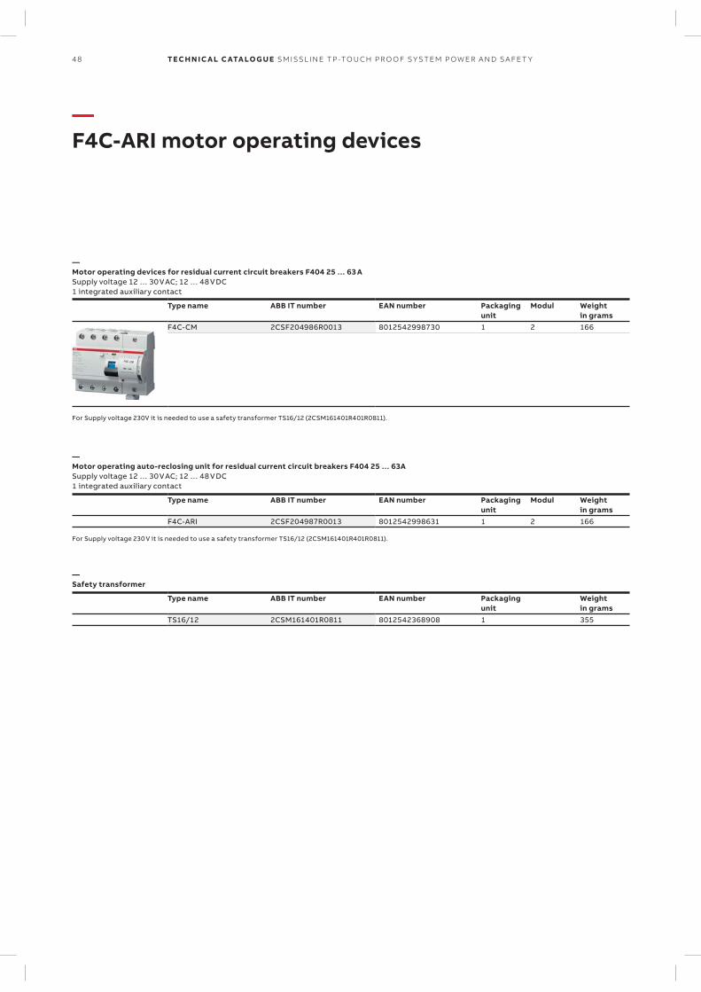
48 TECH N I C A L C ATA LO G U E SM ISSL I N E TP -TO U CH PR O O F S Y S TEM P OW ER A N D S A FE T Y
—F4C-ARI motor operating devices
—Motor operating devices for residual current circuit breakers F404 25 … 63 ASupply voltage 12 … 30 V AC; 12 … 48 V DC1 integrated auxiliary contact
Type name ABB IT number EAN number Packagingunit
Modul Weightin grams
F4C-CM 2CSF204986R0013 8012542998730 1 2 166
For Supply voltage 230V it is needed to use a safety transformer TS16/12 (2CSM161401R401R0811).
—Motor operating auto-reclosing unit for residual current circuit breakers F404 25 … 63ASupply voltage 12 … 30 V AC; 12 … 48 V DC1 integrated auxiliary contact
Type name ABB IT number EAN number Packagingunit
Modul Weightin grams
F4C-ARI 2CSF204987R0013 8012542998631 1 2 166
For Supply voltage 230 V it is needed to use a safety transformer TS16/12 (2CSM161401R401R0811).
—Safety transformer
Type name ABB IT number EAN number Packagingunit
Weightin grams
TS16/12 2CSM161401R0811 8012542368908 1 355
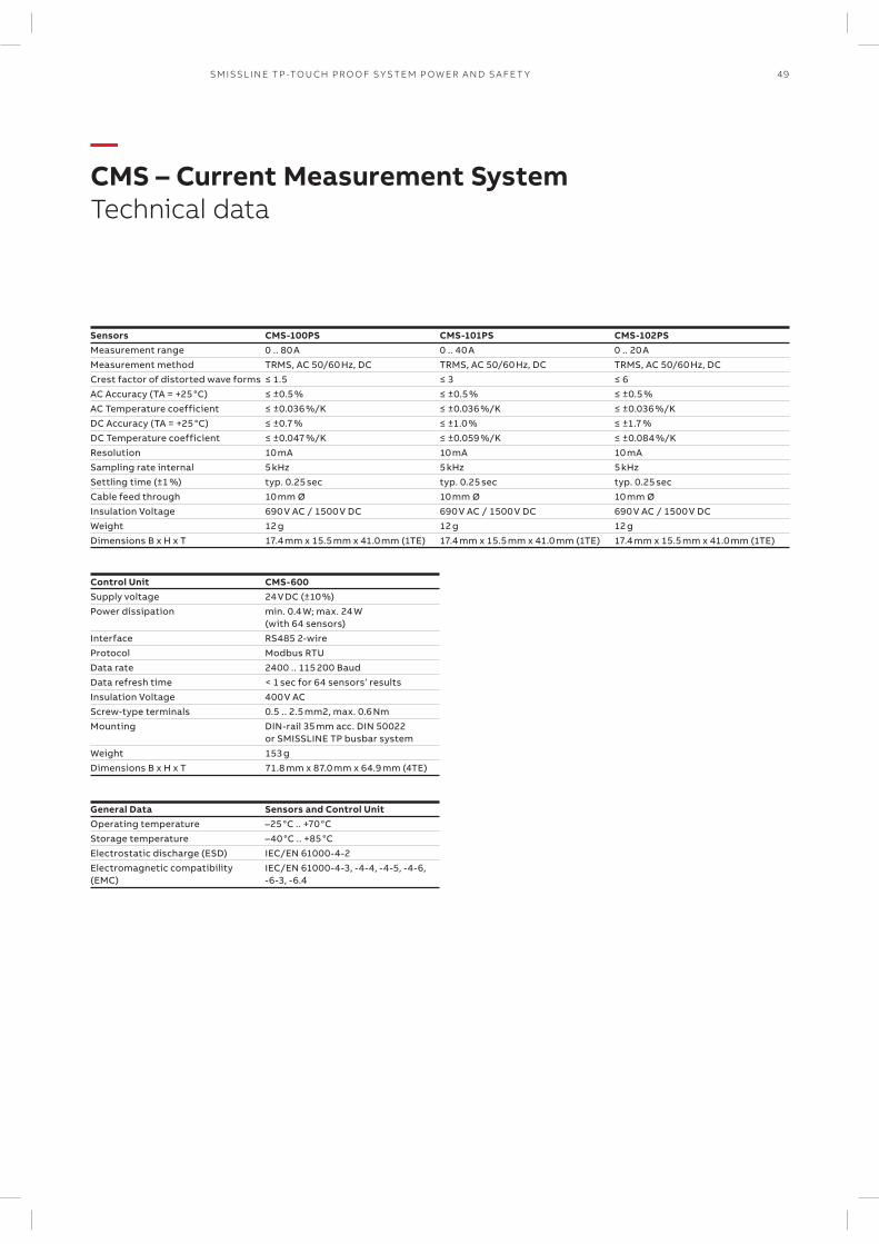
49SM ISSL I N E TP -TO U CH PR O O F S Y S TEM P OW ER A N D S A FE T Y
—CMS – Current Measurement SystemTechnical data
Sensors CMS-100PS CMS-101PS CMS-102PSMeasurement range 0 .. 80 A 0 .. 40 A 0 .. 20 AMeasurement method TRMS, AC 50/60 Hz, DC TRMS, AC 50/60 Hz, DC TRMS, AC 50/60 Hz, DCCrest factor of distorted wave forms ≤ 1.5 ≤ 3 ≤ 6AC Accuracy (TA = +25 °C) ≤ ±0.5 % ≤ ±0.5 % ≤ ±0.5 %AC Temperature coefficient ≤ ±0.036 %/K ≤ ±0.036 %/K ≤ ±0.036 %/KDC Accuracy (TA = +25 °C) ≤ ±0.7 % ≤ ±1.0 % ≤ ±1.7 %DC Temperature coefficient ≤ ±0.047 %/K ≤ ±0.059 %/K ≤ ±0.084 %/KResolution 10 mA 10 mA 10 mASampling rate internal 5 kHz 5 kHz 5 kHzSettling time (±1 %) typ. 0.25 sec typ. 0.25 sec typ. 0.25 secCable feed through 10 mm Ø 10 mm Ø 10 mm ØInsulation Voltage 690 V AC / 1500 V DC 690 V AC / 1500 V DC 690 V AC / 1500 V DC Weight 12 g 12 g 12 gDimensions B x H x T 17.4 mm x 15.5 mm x 41.0 mm (1TE) 17.4 mm x 15.5 mm x 41.0 mm (1TE) 17.4 mm x 15.5 mm x 41.0 mm (1TE)
Control Unit CMS-600Supply voltage 24 V DC (±10 %) Power dissipation min. 0.4 W; max. 24 W
(with 64 sensors)Interface RS485 2-wire Protocol Modbus RTUData rate 2400 .. 115 200 Baud Data refresh time < 1 sec for 64 sensors’ resultsInsulation Voltage 400 V ACScrew-type terminals 0.5 .. 2.5 mm2, max. 0.6 NmMounting DIN-rail 35 mm acc. DIN 50022
or SMISSLINE TP busbar systemWeight 153 gDimensions B x H x T 71.8 mm x 87.0 mm x 64.9 mm (4TE)
General Data Sensors and Control UnitOperating temperature –25 °C .. +70 °CStorage temperature –40 °C .. +85 °CElectrostatic discharge (ESD) IEC/EN 61000-4-2Electromagnetic compatibility (EMC)
IEC/EN 61000-4-3, -4-4, -4-5, -4-6, -6-3, -6.4
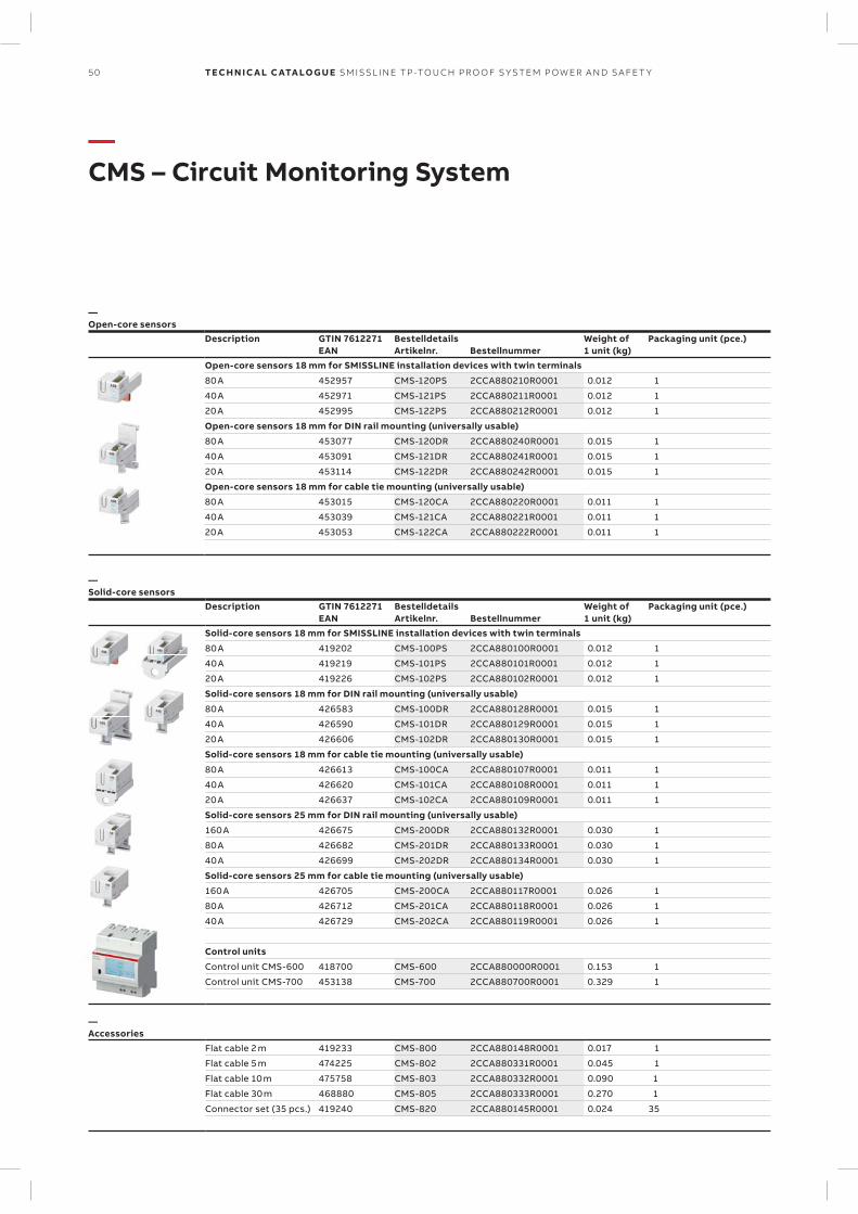
50 TECH N I C A L C ATA LO G U E SM ISSL I N E TP -TO U CH PR O O F S Y S TEM P OW ER A N D S A FE T Y
—CMS – Circuit Monitoring System
—Open-core sensors
Description GTIN 7612271EAN
BestelldetailsArtikelnr. Bestellnummer
Weight of1 unit (kg)
Packaging unit (pce.)
Open-core sensors 18 mm for SMISSLINE installation devices with twin terminals
80 A 452957 CMS-120PS 2CCA880210R0001 0.012 1
40 A 452971 CMS-121PS 2CCA880211R0001 0.012 1
20 A 452995 CMS-122PS 2CCA880212R0001 0.012 1
Open-core sensors 18 mm for DIN rail mounting (universally usable)
80 A 453077 CMS-120DR 2CCA880240R0001 0.015 1
40 A 453091 CMS-121DR 2CCA880241R0001 0.015 1
20 A 453114 CMS-122DR 2CCA880242R0001 0.015 1
Open-core sensors 18 mm for cable tie mounting (universally usable)
80 A 453015 CMS-120CA 2CCA880220R0001 0.011 1
40 A 453039 CMS-121CA 2CCA880221R0001 0.011 1
20 A 453053 CMS-122CA 2CCA880222R0001 0.011 1
—Solid-core sensors
Description GTIN 7612271EAN
BestelldetailsArtikelnr. Bestellnummer
Weight of1 unit (kg)
Packaging unit (pce.)
Solid-core sensors 18 mm for SMISSLINE installation devices with twin terminals
80 A 419202 CMS-100PS 2CCA880100R0001 0.012 1
40 A 419219 CMS-101PS 2CCA880101R0001 0.012 1
20 A 419226 CMS-102PS 2CCA880102R0001 0.012 1
Solid-core sensors 18 mm for DIN rail mounting (universally usable)
80 A 426583 CMS-100DR 2CCA880128R0001 0.015 1
40 A 426590 CMS-101DR 2CCA880129R0001 0.015 1
20 A 426606 CMS-102DR 2CCA880130R0001 0.015 1
Solid-core sensors 18 mm for cable tie mounting (universally usable)
80 A 426613 CMS-100CA 2CCA880107R0001 0.011 1
40 A 426620 CMS-101CA 2CCA880108R0001 0.011 1
20 A 426637 CMS-102CA 2CCA880109R0001 0.011 1
Solid-core sensors 25 mm for DIN rail mounting (universally usable)
160 A 426675 CMS-200DR 2CCA880132R0001 0.030 1
80 A 426682 CMS-201DR 2CCA880133R0001 0.030 1
40 A 426699 CMS-202DR 2CCA880134R0001 0.030 1
Solid-core sensors 25 mm for cable tie mounting (universally usable)
160 A 426705 CMS-200CA 2CCA880117R0001 0.026 1
80 A 426712 CMS-201CA 2CCA880118R0001 0.026 1
40 A 426729 CMS-202CA 2CCA880119R0001 0.026 1
Control units
Control unit CMS-600 418700 CMS-600 2CCA880000R0001 0.153 1
Control unit CMS-700 453138 CMS-700 2CCA880700R0001 0.329 1
—Accessories
Flat cable 2 m 419233 CMS-800 2CCA880148R0001 0.017 1
Flat cable 5 m 474225 CMS-802 2CCA880331R0001 0.045 1
Flat cable 10 m 475758 CMS-803 2CCA880332R0001 0.090 1
Flat cable 30 m 468880 CMS-805 2CCA880333R0001 0.270 1
Connector set (35 pcs.) 419240 CMS-820 2CCA880145R0001 0.024 35
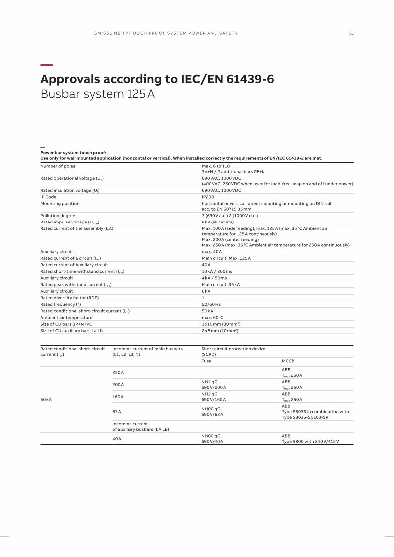
51SM ISSL I N E TP -TO U CH PR O O F S Y S TEM P OW ER A N D S A FE T Y
—Approvals according to IEC/EN 61439-6Busbar system 125 A
—Power bar system touch proof:Use only for wall mounted application (horizontal or vertical). When installed correctly the requirements of EN/IEC 61439-2 are met.
Number of poles max. 6 to 1103p+N / 2 additional bars PE+N
Rated operational voltage (Ue) 690 VAC, 1000 VDC(400 VAC, 250 VDC when used for load-free snap on and off under power)
Rated insulation voltage (Ui) 690 VAC, 1000 VDCIP Code IP20B Mounting position horizontal or vertical, direct mounting or mounting on DIN rail
acc. to EN 60715 35 mmPollution degree 3 (690 V a.c.) 2 (1000 V d.c.)Rated impulse voltage (Uimp) 8 kV (all cicuits)Rated current of the assembly (InA) Max. 100 A (side feeding), max. 125 A (max. 35 °C Ambient air
temperature for 125 A continuously) Max. 200 A (center feeding)Max. 250 A (max. 35 °C Ambient air temperature for 250 A continuously)
Auxiliary circuit max. 40 ARated current of a circuit (Inc) Main circuit: Max. 125 ARated current of Auxiliary circuit 40 ARated short-time withstand current (Icw) 10 kA / 300 msAuxiliary circuit 4 kA / 50 msRated peak withstand current (Ipk) Main circuit: 35 kAAuxiliary circuit 6 kARated diversity factor (RDF) 1Rated frequency (f) 50/60 HzRated conditional short-circuit current (Icc) 50 kA Ambient air temperature max. 60°CSize of CU bars 3P+N+PE 3 x10 mm (30 mm2)Size of CU auxiliary bars La Lb 2 x 5 mm (10 mm2)
Rated conditional short-circuit current (Icc)
Incoming current of main busbars (L1, L2, L3, N)
Short circuit protection device (SCPD)Fuse MCCB
50 kA
250 AABB Tmax 250 A
200 ANH1 gG 690 V/200 A
ABB Tmax 250 A
160 ANH1 gG 690 V/160 A
ABB Tmax 250 A
63 ANH00 gG 690 V/63 A
ABB Type S803S in combination with Type S803S-SCL63-SR
Incoming current of auxiliary busbars (LA LB)
40 ANH00 gG 690 V/40 A
ABB Type S800 with 240 V/415 V
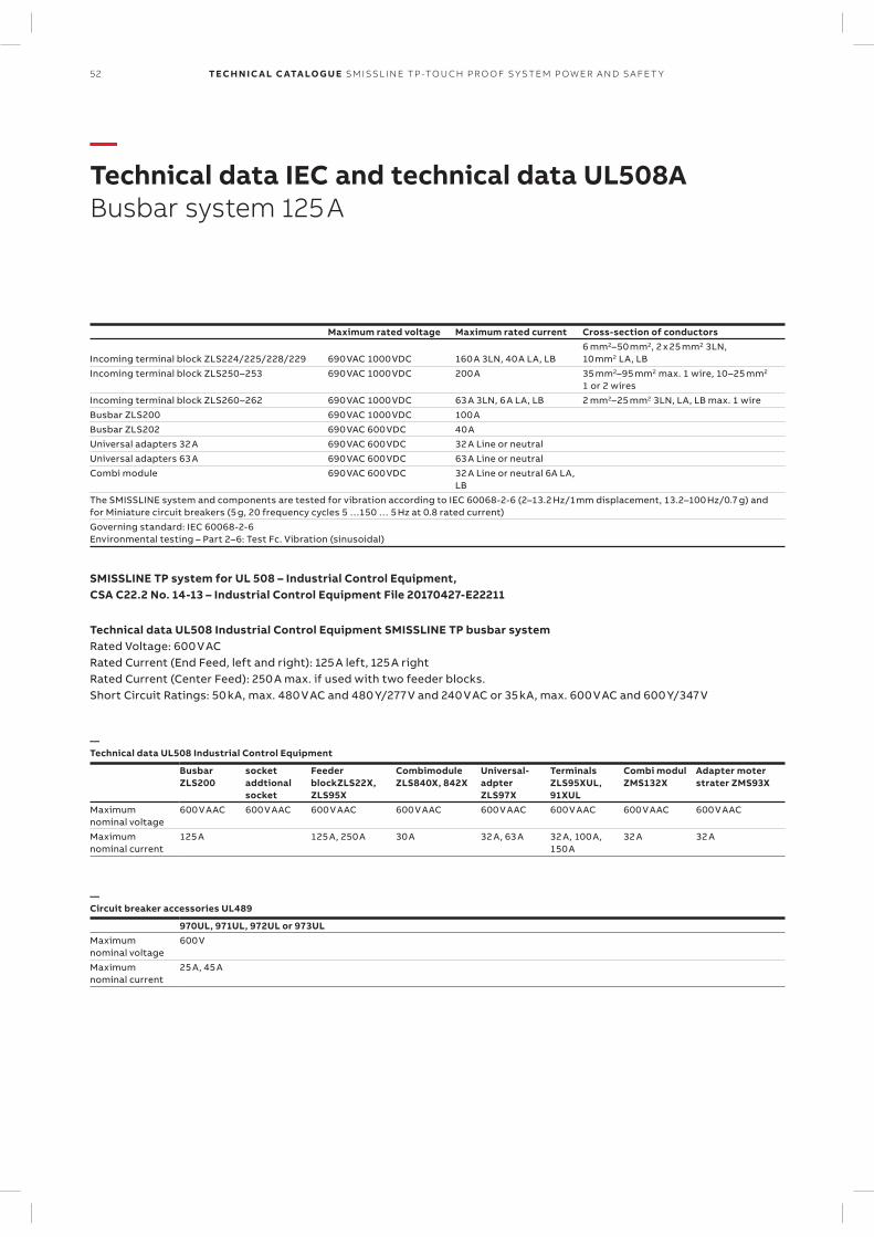
52 TECH N I C A L C ATA LO G U E SM ISSL I N E TP -TO U CH PR O O F S Y S TEM P OW ER A N D S A FE T Y
—Technical data IEC and technical data UL508A Busbar system 125 A
Maximum rated voltage Maximum rated current Cross-section of conductors
Incoming terminal block ZLS224/225/228/229 690 VAC 1000 VDC 160 A 3LN, 40 A LA, LB6 mm2–50 mm2, 2 x 25 mm2 3LN, 10 mm2 LA, LB
Incoming terminal block ZLS250–253 690 VAC 1000 VDC 200 A 35 mm2–95 mm2 max. 1 wire, 10–25 mm2 1 or 2 wires
Incoming terminal block ZLS260–262 690 VAC 1000 VDC 63 A 3LN, 6 A LA, LB 2 mm2–25 mm2 3LN, LA, LB max. 1 wireBusbar ZLS200 690 VAC 1000 VDC 100 ABusbar ZLS202 690 VAC 600 VDC 40 AUniversal adapters 32 A 690 VAC 600 VDC 32 A Line or neutralUniversal adapters 63 A 690 VAC 600 VDC 63 A Line or neutralCombi module 690 VAC 600 VDC 32 A Line or neutral 6A LA,
LBThe SMISSLINE system and components are tested for vibration according to IEC 60068-2-6 (2–13.2 Hz/1 mm displacement, 13.2–100 Hz/0.7 g) and for Miniature circuit breakers (5 g, 20 frequency cycles 5 …150 … 5 Hz at 0.8 rated current)Governing standard: IEC 60068-2-6 Environmental testing – Part 2–6: Test Fc. Vibration (sinusoidal)
SMISSLINE TP system for UL 508 – Industrial Control Equipment,CSA C22.2 No. 14-13 – Industrial Control Equipment File 20170427-E22211
Technical data UL508 Industrial Control Equipment SMISSLINE TP busbar systemRated Voltage: 600 V AC Rated Current (End Feed, left and right): 125 A left, 125 A right Rated Current (Center Feed): 250 A max. if used with two feeder blocks. Short Circuit Ratings: 50 kA, max. 480 V AC and 480 Y/277 V and 240 V AC or 35 kA, max. 600 V AC and 600 Y/347 V
—Technical data UL508 Industrial Control Equipment
Busbar ZLS200
socket addtional socket
Feeder blockZLS22X, ZLS95X
Combimodule ZLS840X, 842X
Universal-adpter ZLS97X
Terminals ZLS95XUL, 91XUL
Combi modul ZMS132X
Adapter moter strater ZMS93X
Maximum nominal voltage
600 V AAC 600 V AAC 600 V AAC 600 V AAC 600 V AAC 600 V AAC 600 V AAC 600 V AAC
Maximum nominal current
125 A 125 A, 250 A 30 A 32 A, 63 A 32 A, 100 A, 150 A
32 A 32 A
—Circuit breaker accessories UL489
970UL, 971UL, 972UL or 973ULMaximum nominal voltage
600 V
Maximum nominal current
25 A, 45 A
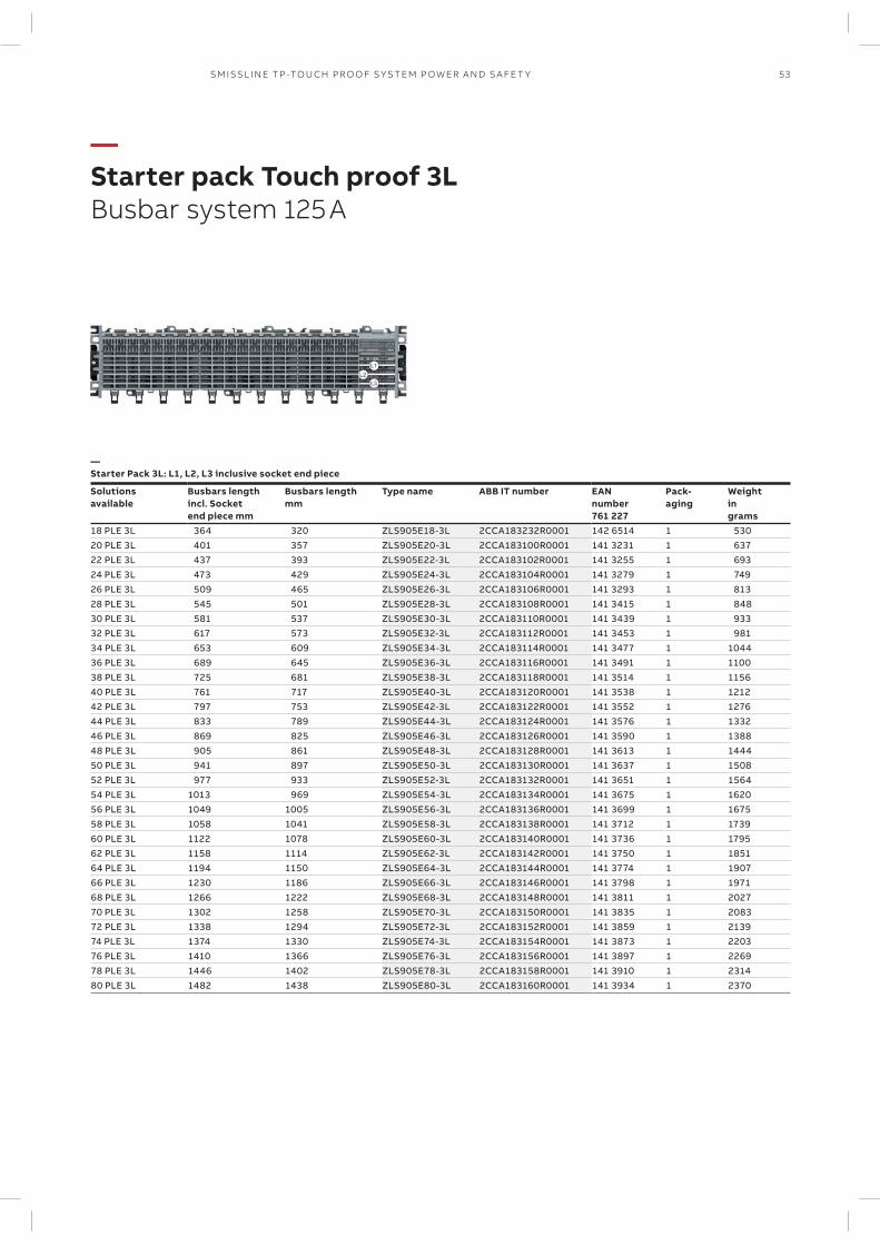
—Starter Pack 3L: L1, L2, L3 inclusive socket end piece
Solutionsavailable
Busbars lengthincl. Socketend piece mm
Busbars lengthmm
Type name ABB IT number EAN number761 227
Pack-aging
Weightingrams
18 PLE 3L 364 320 ZLS905E18-3L 2CCA183232R0001 142 6514 1 53020 PLE 3L 401 357 ZLS905E20-3L 2CCA183100R0001 141 3231 1 63722 PLE 3L 437 393 ZLS905E22-3L 2CCA183102R0001 141 3255 1 69324 PLE 3L 473 429 ZLS905E24-3L 2CCA183104R0001 141 3279 1 74926 PLE 3L 509 465 ZLS905E26-3L 2CCA183106R0001 141 3293 1 81328 PLE 3L 545 501 ZLS905E28-3L 2CCA183108R0001 141 3415 1 84830 PLE 3L 581 537 ZLS905E30-3L 2CCA183110R0001 141 3439 1 93332 PLE 3L 617 573 ZLS905E32-3L 2CCA183112R0001 141 3453 1 98134 PLE 3L 653 609 ZLS905E34-3L 2CCA183114R0001 141 3477 1 104436 PLE 3L 689 645 ZLS905E36-3L 2CCA183116R0001 141 3491 1 110038 PLE 3L 725 681 ZLS905E38-3L 2CCA183118R0001 141 3514 1 115640 PLE 3L 761 717 ZLS905E40-3L 2CCA183120R0001 141 3538 1 121242 PLE 3L 797 753 ZLS905E42-3L 2CCA183122R0001 141 3552 1 127644 PLE 3L 833 789 ZLS905E44-3L 2CCA183124R0001 141 3576 1 133246 PLE 3L 869 825 ZLS905E46-3L 2CCA183126R0001 141 3590 1 138848 PLE 3L 905 861 ZLS905E48-3L 2CCA183128R0001 141 3613 1 144450 PLE 3L 941 897 ZLS905E50-3L 2CCA183130R0001 141 3637 1 150852 PLE 3L 977 933 ZLS905E52-3L 2CCA183132R0001 141 3651 1 156454 PLE 3L 1013 969 ZLS905E54-3L 2CCA183134R0001 141 3675 1 162056 PLE 3L 1049 1005 ZLS905E56-3L 2CCA183136R0001 141 3699 1 167558 PLE 3L 1058 1041 ZLS905E58-3L 2CCA183138R0001 141 3712 1 173960 PLE 3L 1122 1078 ZLS905E60-3L 2CCA183140R0001 141 3736 1 179562 PLE 3L 1158 1114 ZLS905E62-3L 2CCA183142R0001 141 3750 1 185164 PLE 3L 1194 1150 ZLS905E64-3L 2CCA183144R0001 141 3774 1 190766 PLE 3L 1230 1186 ZLS905E66-3L 2CCA183146R0001 141 3798 1 197168 PLE 3L 1266 1222 ZLS905E68-3L 2CCA183148R0001 141 3811 1 202770 PLE 3L 1302 1258 ZLS905E70-3L 2CCA183150R0001 141 3835 1 208372 PLE 3L 1338 1294 ZLS905E72-3L 2CCA183152R0001 141 3859 1 213974 PLE 3L 1374 1330 ZLS905E74-3L 2CCA183154R0001 141 3873 1 220376 PLE 3L 1410 1366 ZLS905E76-3L 2CCA183156R0001 141 3897 1 226978 PLE 3L 1446 1402 ZLS905E78-3L 2CCA183158R0001 141 3910 1 231480 PLE 3L 1482 1438 ZLS905E80-3L 2CCA183160R0001 141 3934 1 2370
53SM ISSL I N E TP -TO U CH PR O O F S Y S TEM P OW ER A N D S A FE T Y
—Starter pack Touch proof 3L Busbar system 125 A
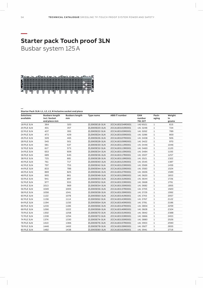
54 TECH N I C A L C ATA LO G U E SM ISSL I N E TP -TO U CH PR O O F S Y S TEM P OW ER A N D S A FE T Y
—Starter pack Touch proof 3LN Busbar system 125 A
—Starter Pack 3LN: L1, L2, L3, N inclusive socket end piece
Solutionsavailable
Busbars lengthincl. Socketend piece mm
Busbars lengthmm
Type name ABB IT number EAN number761 227
Pack-aging
Weightingrams
18 PLE 3LN 364 320 ZLS905E18-3LN 2CCA183234R0001 142 6521 1 61520 PLE 3LN 401 357 ZLS905E20-3LN 2CCA183101R0001 141 3248 1 72422 PLE 3LN 437 393 ZLS905E22-3LN 2CCA183103R0001 141 3262 1 78924 PLE 3LN 473 429 ZLS905E24-3LN 2CCA183105R0001 141 3286 1 80026 PLE 3LN 509 465 ZLS905E26-3LN 2CCA183107R0001 141 3408 1 92628 PLE 3LN 545 501 ZLS905E28-3LN 2CCA183109R0001 141 3422 1 97030 PLE 3LN 581 537 ZLS905E30-3LN 2CCA183111R0001 141 3446 1 104632 PLE 3LN 617 573 ZLS905E32-3LN 2CCA183113R0001 141 3460 1 112034 PLE 3LN 653 609 ZLS905E34-3LN 2CCA183115R0001 141 3484 1 119336 PLE 3LN 689 645 ZLS905E36-3LN 2CCA183117R0001 141 3507 1 125738 PLE 3LN 725 681 ZLS905E38-3LN 2CCA183119R0001 141 3521 1 132240 PLE 3LN 761 717 ZLS905E40-3LN 2CCA183121R0001 141 3545 1 138742 PLE 3LN 797 753 ZLS905E42-3LN 2CCA183123R0001 141 3569 1 145944 PLE 3LN 833 789 ZLS905E44-3LN 2CCA183125R0001 141 3583 1 152446 PLE 3LN 869 825 ZLS905E46-3LN 2CCA183127R0001 141 3606 1 158948 PLE 3LN 905 861 ZLS905E48-3LN 2CCA183129R0001 141 3620 1 165350 PLE 3LN 941 897 ZLS905E50-3LN 2CCA183131R0001 141 3644 1 172652 PLE 3LN 977 933 ZLS905E52-3LN 2CCA183133R0001 141 3668 1 179154 PLE 3LN 1013 969 ZLS905E54-3LN 2CCA183135R0001 141 3682 1 185556 PLE 3LN 1049 1005 ZLS905E56-3LN 2CCA183137R0001 141 3705 1 192058 PLE 3LN 1058 1041 ZLS905E58-3LN 2CCA183139R0001 141 3729 1 199260 PLE 3LN 1122 1078 ZLS905E60-3LN 2CCA183141R0001 141 3743 1 205762 PLE 3LN 1158 1114 ZLS905E62-3LN 2CCA183143R0001 141 3767 1 212264 PLE 3LN 1194 1150 ZLS905E64-3LN 2CCA183145R0001 141 3781 1 218666 PLE 3LN 1230 1186 ZLS905E66-3LN 2CCA183147R0001 141 3804 1 225968 PLE 3LN 1266 1222 ZLS905E68-3LN 2CCA183149R0001 141 3828 1 232470 PLE 3LN 1302 1258 ZLS905E70-3LN 2CCA183151R0001 141 3842 1 238872 PLE 3LN 1338 1294 ZLS905E72-3LN 2CCA183153R0001 141 3866 1 245374 PLE 3LN 1374 1330 ZLS905E74-3LN 2CCA183155R0001 141 3880 1 252676 PLE 3LN 1410 1366 ZLS905E76-3LN 2CCA183157R0001 141 3903 1 259078 PLE 3LN 1446 1402 ZLS905E78-3LN 2CCA183159R0001 141 3927 1 265580 PLE 3LN 1482 1438 ZLS905E80-3LN 2CCA183161R0001 141 3941 1 2719
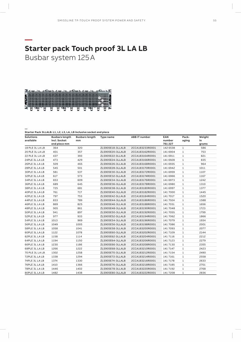
55SM ISSL I N E TP -TO U CH PR O O F S Y S TEM P OW ER A N D S A FE T Y
—Starter pack Touch proof 3L LA LB Busbar system 125 A
—Starter Pack 3LLALB: L1, L2, L3, LA, LB inclusive socket end piece
Solutionsavailable
Busbars lengthincl. Socketend piece mm
Busbars lengthmm
Type name ABB IT number EAN number761 227
Pack-aging
Weightingrams
18 PLE 3L LA LB 364 320 ZLS905E18-3LLALB 2CCA183233R0001 142 6538 1 58620 PLE 3L LA LB 401 357 ZLS905E20-3LLALB 2CCA183162R0001 141 6904 1 75322 PLE 3L LA LB 437 393 ZLS905E22-3LLALB 2CCA183164R0001 141 6911 1 82124PLE 3L LA LB 473 429 ZLS905E24-3LLALB 2CCA183166R0001 141 6928 1 83526PLE 3L LA LB 509 465 ZLS905E26-3LLALB 2CCA183168R0001 141 6935 1 96428PLE 3L LA LB 545 501 ZLS905E28-3LLALB 2CCA183170R0001 141 6942 1 101130PLE 3L LA LB 581 537 ZLS905E30-3LLALB 2CCA183172R0001 141 6959 1 110732PLE 3L LA LB 617 573 ZLS905E32-3LLALB 2CCA183174R0001 141 6966 1 116734PLE 3L LA LB 653 609 ZLS905E34-3LLALB 2CCA183176R0001 141 6973 1 124236PLE 3L LA LB 689 645 ZLS905E36-3LLALB 2CCA183178R0001 141 6980 1 131038PLE 3L LA LB 725 681 ZLS905E38-3LLALB 2CCA183180R0001 141 6997 1 137740PLE 3L LA LB 761 717 ZLS905E40-3LLALB 2CCA183182R0001 141 7000 1 144542PLE 3L LA LB 797 753 ZLS905E42-3LLALB 2CCA183184R0001 141 7017 1 152044PLE 3L LA LB 833 789 ZLS905E44-3LLALB 2CCA183186R0001 141 7024 1 158846PLE 3L LA LB 869 825 ZLS905E46-3LLALB 2CCA183188R0001 141 7031 1 165648PLE 3L LA LB 905 861 ZLS905E48-3LLALB 2CCA183190R0001 141 7048 1 172350PLE 3L LA LB 941 897 ZLS905E50-3LLALB 2CCA183192R0001 141 7055 1 179952PLE 3L LA LB 977 933 ZLS905E52-3LLALB 2CCA183194R0001 141 7062 1 186654PLE 3L LA LB 1013 969 ZLS905E54-3LLALB 2CCA183196R0001 141 7079 1 193456PLE 3L LA LB 1049 1005 ZLS905E56-3LLALB 2CCA183198R0001 141 7086 1 200158PLE 3L LA LB 1058 1041 ZLS905E58-3LLALB 2CCA183200R0001 141 7093 1 207760PLE 3L LA LB 1122 1078 ZLS905E60-3LLALB 2CCA183202R0001 141 7109 1 214462PLE 3L LA LB 1158 1114 ZLS905E62-3LLALB 2CCA183204R0001 141 7116 1 221264PLE 3L LA LB 1194 1150 ZLS905E64-3LLALB 2CCA183206R0001 141 7123 1 227966PLE 3L LA LB 1230 1186 ZLS905E66-3LLALB 2CCA183208R0001 141 7130 1 235568PLE 3L LA LB 1266 1222 ZLS905E68-3LLALB 2CCA183210R0001 141 7147 1 242370 PLE 3L LA LB 1302 1258 ZLS905E70-3LLALB 2CCA183212R0001 141 7154 1 249072PLE 3L LA LB 1338 1294 ZLS905E72-3LLALB 2CCA183214R0001 141 7161 1 255874PLE 3L LA LB 1374 1330 ZLS905E74-3LLALB 2CCA183216R0001 141 7178 1 263376PLE 3L LA LB 1410 1366 ZLS905E76-3LLALB 2CCA183218R0001 141 7185 1 270178PLE 3L LA LB 1446 1402 ZLS905E78-3LLALB 2CCA183220R0001 141 7192 1 276880PLE 3L LA LB 1482 1438 ZLS905E80-3LLALB 2CCA183222R0001 141 7208 1 2836
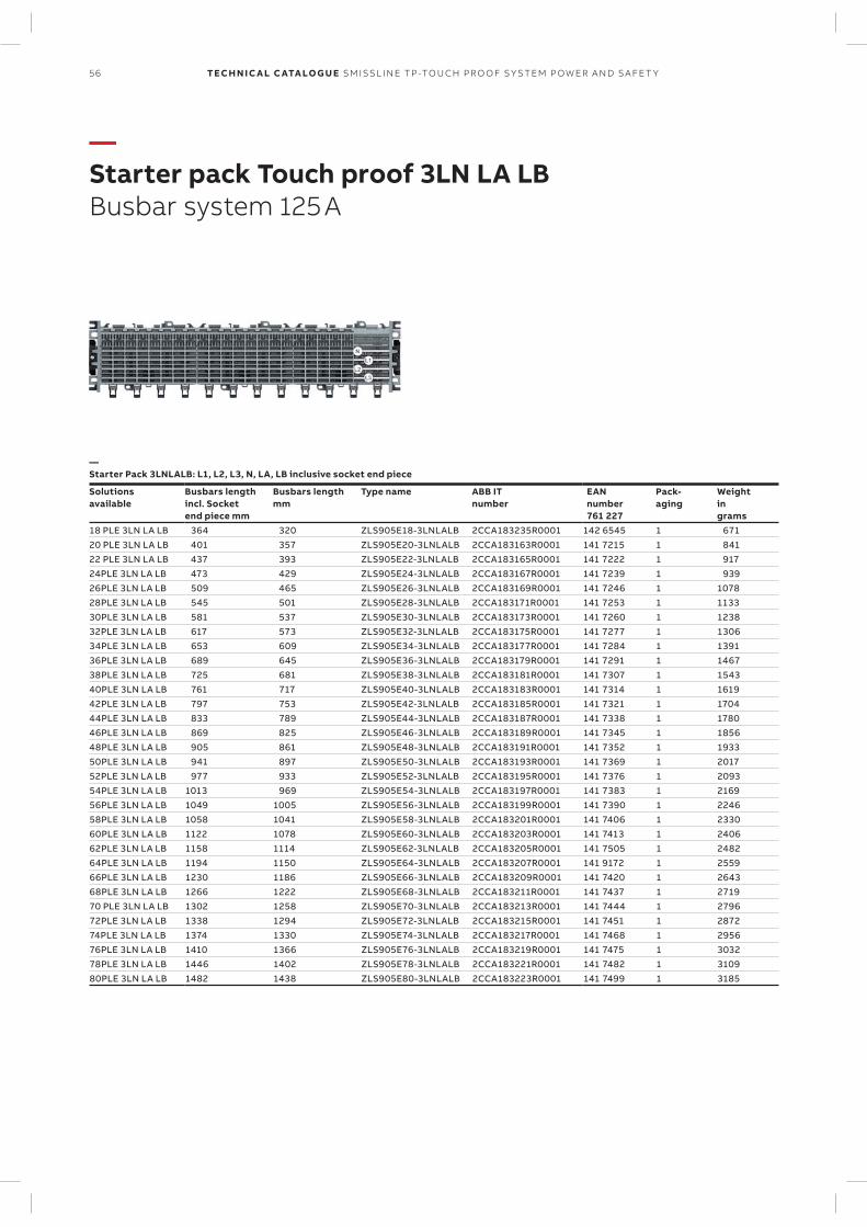
56 TECH N I C A L C ATA LO G U E SM ISSL I N E TP -TO U CH PR O O F S Y S TEM P OW ER A N D S A FE T Y
—Starter pack Touch proof 3LN LA LB Busbar system 125 A
—Starter Pack 3LNLALB: L1, L2, L3, N, LA, LB inclusive socket end piece
Solutionsavailable
Busbars lengthincl. Socketend piece mm
Busbars lengthmm
Type name ABB ITnumber
EAN number761 227
Pack-aging
Weightingrams
18 PLE 3LN LA LB 364 320 ZLS905E18-3LNLALB 2CCA183235R0001 142 6545 1 67120 PLE 3LN LA LB 401 357 ZLS905E20-3LNLALB 2CCA183163R0001 141 7215 1 84122 PLE 3LN LA LB 437 393 ZLS905E22-3LNLALB 2CCA183165R0001 141 7222 1 91724PLE 3LN LA LB 473 429 ZLS905E24-3LNLALB 2CCA183167R0001 141 7239 1 93926PLE 3LN LA LB 509 465 ZLS905E26-3LNLALB 2CCA183169R0001 141 7246 1 107828PLE 3LN LA LB 545 501 ZLS905E28-3LNLALB 2CCA183171R0001 141 7253 1 113330PLE 3LN LA LB 581 537 ZLS905E30-3LNLALB 2CCA183173R0001 141 7260 1 123832PLE 3LN LA LB 617 573 ZLS905E32-3LNLALB 2CCA183175R0001 141 7277 1 130634PLE 3LN LA LB 653 609 ZLS905E34-3LNLALB 2CCA183177R0001 141 7284 1 139136PLE 3LN LA LB 689 645 ZLS905E36-3LNLALB 2CCA183179R0001 141 7291 1 146738PLE 3LN LA LB 725 681 ZLS905E38-3LNLALB 2CCA183181R0001 141 7307 1 154340PLE 3LN LA LB 761 717 ZLS905E40-3LNLALB 2CCA183183R0001 141 7314 1 161942PLE 3LN LA LB 797 753 ZLS905E42-3LNLALB 2CCA183185R0001 141 7321 1 170444PLE 3LN LA LB 833 789 ZLS905E44-3LNLALB 2CCA183187R0001 141 7338 1 178046PLE 3LN LA LB 869 825 ZLS905E46-3LNLALB 2CCA183189R0001 141 7345 1 185648PLE 3LN LA LB 905 861 ZLS905E48-3LNLALB 2CCA183191R0001 141 7352 1 193350PLE 3LN LA LB 941 897 ZLS905E50-3LNLALB 2CCA183193R0001 141 7369 1 201752PLE 3LN LA LB 977 933 ZLS905E52-3LNLALB 2CCA183195R0001 141 7376 1 209354PLE 3LN LA LB 1013 969 ZLS905E54-3LNLALB 2CCA183197R0001 141 7383 1 216956PLE 3LN LA LB 1049 1005 ZLS905E56-3LNLALB 2CCA183199R0001 141 7390 1 224658PLE 3LN LA LB 1058 1041 ZLS905E58-3LNLALB 2CCA183201R0001 141 7406 1 233060PLE 3LN LA LB 1122 1078 ZLS905E60-3LNLALB 2CCA183203R0001 141 7413 1 240662PLE 3LN LA LB 1158 1114 ZLS905E62-3LNLALB 2CCA183205R0001 141 7505 1 248264PLE 3LN LA LB 1194 1150 ZLS905E64-3LNLALB 2CCA183207R0001 141 9172 1 255966PLE 3LN LA LB 1230 1186 ZLS905E66-3LNLALB 2CCA183209R0001 141 7420 1 264368PLE 3LN LA LB 1266 1222 ZLS905E68-3LNLALB 2CCA183211R0001 141 7437 1 271970 PLE 3LN LA LB 1302 1258 ZLS905E70-3LNLALB 2CCA183213R0001 141 7444 1 279672PLE 3LN LA LB 1338 1294 ZLS905E72-3LNLALB 2CCA183215R0001 141 7451 1 287274PLE 3LN LA LB 1374 1330 ZLS905E74-3LNLALB 2CCA183217R0001 141 7468 1 295676PLE 3LN LA LB 1410 1366 ZLS905E76-3LNLALB 2CCA183219R0001 141 7475 1 303278PLE 3LN LA LB 1446 1402 ZLS905E78-3LNLALB 2CCA183221R0001 141 7482 1 310980PLE 3LN LA LB 1482 1438 ZLS905E80-3LNLALB 2CCA183223R0001 141 7499 1 3185
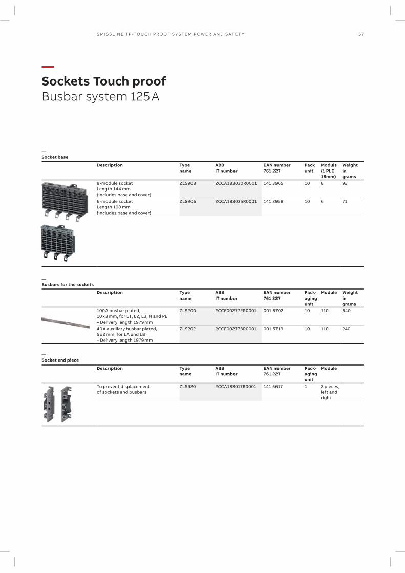
57SM ISSL I N E TP -TO U CH PR O O F S Y S TEM P OW ER A N D S A FE T Y
—Sockets Touch proofBusbar system 125 A
—Socket base
Description Type name
ABB IT number
EAN number 761 227
Pack unit
Moduls (1 PLE 18mm)
Weight in grams
8-module socket Length 144 mm (includes base and cover)
ZLS908 2CCA183030R0001 141 3965 10 8 92
6-module socket Length 108 mm (includes base and cover)
ZLS906 2CCA183035R0001 141 3958 10 6 71
—Busbars for the sockets
Description Type name
ABB IT number
EAN number 761 227
Pack- aging unit
Module Weight in grams
100 A busbar plated, 10 x 3 mm, for L1, L2, L3, N and PE – Delivery length 1979 mm
ZLS200 2CCF002772R0001 001 5702 10 110 640
40 A auxiliary busbar plated, 5 x 2 mm, for LA und LB – Delivery length 1979 mm
ZLS202 2CCF002773R0001 001 5719 10 110 240
—Socket end piece
Description Type name
ABB IT number
EAN number 761 227
Pack- aging unit
Module
To prevent displacement of sockets and busbars
ZLS920 2CCA183017R0001 141 5617 1 2 pieces, left and right
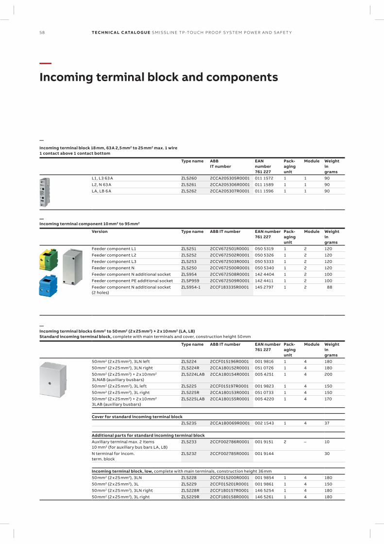
58 TECH N I C A L C ATA LO G U E SM ISSL I N E TP -TO U CH PR O O F S Y S TEM P OW ER A N D S A FE T Y
—Incoming terminal block and components
—
Incoming terminal block 18 mm, 63 A 2,5 mm2 to 25 mm2 max. 1 wire1 contact above 1 contact bottom
Type name ABBIT number
EANnumber761 227
Pack-agingunit
Module Weightingrams
L1, L3 63 A ZLS260 2CCA205305R0001 011 1572 1 1 90L2, N 63 A ZLS261 2CCA205306R0001 011 1589 1 1 90LA, LB 6 A ZLS262 2CCA205307R0001 011 1596 1 1 90
—Incoming terminal component 10 mm2 to 95 mm2
Version Type name ABB IT number EAN number761 227
Pack-agingunit
Module Weightingrams
Feeder component L1 ZLS251 2CCV672501R0001 050 5319 1 2 120Feeder component L2 ZLS252 2CCV672502R0001 050 5326 1 2 120Feeder component L3 ZLS253 2CCV672503R0001 050 5333 1 2 120Feeder component N ZLS250 2CCV672500R0001 050 5340 1 2 120Feeder component N additional socket ZLS954 2CCV672508R0001 142 4404 1 2 100Feeder component PE additional socket ZLSP959 2CCV672509R0001 142 4411 1 2 100Feeder component N additional socket(2 holes)
ZLS954-1 2CCF183335R0001 145 2797 1 2 88
—Incoming terminal blocks 6 mm2 to 50 mm2 (2 x 25 mm2) + 2 x 10 mm2 (LA, LB)Standard incoming terminal block, complete with main terminals and cover, construction height 50 mm
Type name ABB IT number EAN number761 227
Pack-agingunit
Module Weightingrams
50 mm2 (2 x 25 mm2), 3LN left ZLS224 2CCF015196R0001 001 9816 1 4 18050 mm2 (2 x 25 mm2), 3LN right ZLS224R 2CCA180152R0001 051 0726 1 4 18050 mm2 (2 x 25 mm2) + 2 x 10 mm2
3LNAB (auxiliary busbars)ZLS224LAB 2CCA180154R0001 005 4251 1 4 200
50 mm2 (2 x 25 mm2), 3L left ZLS225 2CCF015197R0001 001 9823 1 4 15050 mm2 (2 x 25 mm2), 3L right ZLS225R 2CCA180153R0001 051 0733 1 4 15050 mm2 (2 x 25 mm2) + 2 x 10 mm2
3LAB (auxiliary busbars)ZLS225LAB 2CCA180155R0001 005 4220 1 4 170
Cover for standard incoming terminal blockZLS235 2CCA180069R0001 002 1543 1 4 37
Additional parts for standard incoming terminal blockAuxiliary terminal max. 2 items 10 mm2 (for auxiliary bus bars LA, LB)
ZLS233 2CCF002786R0001 001 9151 2 – 10
N terminal for incom.term. block
ZLS232 2CCF002785R0001 001 9144 30
Incoming terminal block, low, complete with main terminals, construction height 36 mm50 mm2 (2 x 25 mm2), 3LN ZLS228 2CCF015200R0001 001 9854 1 4 18050 mm2 (2 x 25 mm2), 3L ZLS229 2CCF015201R0001 001 9861 1 4 15050 mm2 (2 x 25 mm2), 3LN right ZLS228R 2CCF180157R0001 146 5254 1 4 18050 mm2 (2 x 25 mm2), 3L right ZLS229R 2CCF180158R0001 146 5261 1 4 180
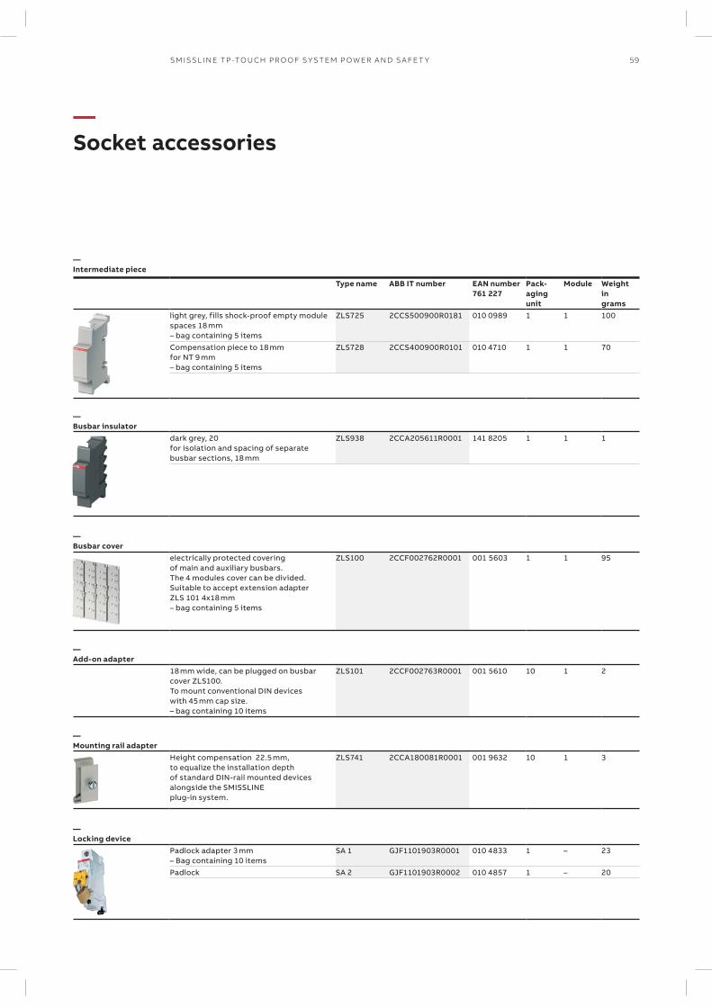
59SM ISSL I N E TP -TO U CH PR O O F S Y S TEM P OW ER A N D S A FE T Y
—Socket accessories
—Intermediate piece
Type name ABB IT number EAN number761 227
Pack-agingunit
Module Weightingrams
light grey, fills shock-proof empty module spaces 18 mm – bag containing 5 items
ZLS725 2CCS500900R0181 010 0989 1 1 100
Compensation piece to 18 mm for NT 9 mm – bag containing 5 items
ZLS728 2CCS400900R0101 010 4710 1 1 70
—Busbar insulator
dark grey, 20 for isolation and spacing of separate busbar sections, 18 mm
ZLS938 2CCA205611R0001 141 8205 1 1 1
—Busbar cover
electrically protected covering of main and auxiliary busbars. The 4 modules cover can be divided. Suitable to accept extension adapter ZLS 101 4x18 mm – bag containing 5 items
ZLS100 2CCF002762R0001 001 5603 1 1 95
—Add-on adapter
18 mm wide, can be plugged on busbar cover ZLS100. To mount conventional DIN devices with 45 mm cap size. – bag containing 10 items
ZLS101 2CCF002763R0001 001 5610 10 1 2
—Mounting rail adapter
Height compensation 22.5 mm, to equalize the installation depth of standard DIN-rail mounted devices alongside the SMISSLINE plug-in system.
ZLS741 2CCA180081R0001 001 9632 10 1 3
—Locking device
Padlock adapter 3 mm – Bag containing 10 items
SA 1 GJF1101903R0001 010 4833 1 – 23
Padlock SA 2 GJF1101903R0002 010 4857 1 – 20
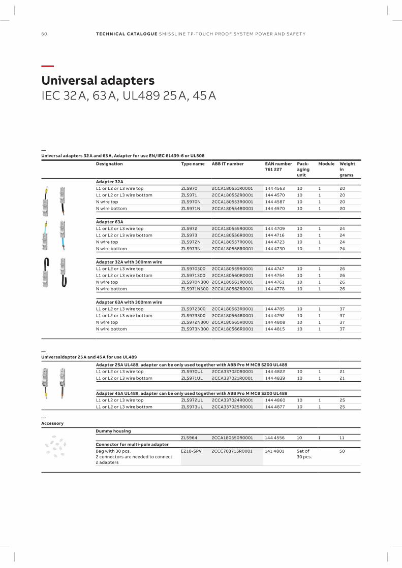
60 TECH N I C A L C ATA LO G U E SM ISSL I N E TP -TO U CH PR O O F S Y S TEM P OW ER A N D S A FE T Y
—Universal adaptersIEC 32 A, 63 A, UL489 25 A, 45 A
—Universal adapters 32 A and 63 A, Adapter for use EN/IEC 61439-6 or UL508
Designation Type name ABB IT number EAN number761 227
Pack-agingunit
Module Weightingrams
Adapter 32AL1 or L2 or L3 wire top ZLS970 2CCA180551R0001 144 4563 10 1 20L1 or L2 or L3 wire bottom ZLS971 2CCA180552R0001 144 4570 10 1 20N wire top ZLS970N 2CCA180553R0001 144 4587 10 1 20N wire bottom ZLS971N 2CCA180554R0001 144 4570 10 1 20
Adapter 63AL1 or L2 or L3 wire top ZLS972 2CCA180555R0001 144 4709 10 1 24L1 or L2 or L3 wire bottom ZLS973 2CCA180556R0001 144 4716 10 1 24N wire top ZLS972N 2CCA180557R0001 144 4723 10 1 24N wire bottom ZLS973N 2CCA180558R0001 144 4730 10 1 24
Adapter 32A with 300mm wireL1 or L2 or L3 wire top ZLS970300 2CCA180559R0001 144 4747 10 1 26L1 or L2 or L3 wire bottom ZLS971300 2CCA180560R0001 144 4754 10 1 26N wire top ZLS970N300 2CCA180561R0001 144 4761 10 1 26N wire bottom ZLS971N300 2CCA180562R0001 144 4778 10 1 26
Adapter 63A with 300mm wireL1 or L2 or L3 wire top ZLS972300 2CCA180563R0001 144 4785 10 1 37L1 or L2 or L3 wire bottom ZLS973300 2CCA180564R0001 144 4792 10 1 37N wire top ZLS972N300 2CCA180565R0001 144 4808 10 1 37N wire bottom ZLS973N300 2CCA180566R0001 144 4815 10 1 37
—Universaldapter 25 A and 45 A for use UL489
Adapter 25A UL489, adapter can be only used together with ABB Pro M MCB S200 UL489L1 or L2 or L3 wire top ZLS970UL 2CCA337020R0001 144 4822 10 1 21L1 or L2 or L3 wire bottom ZLS971UL 2CCA337021R0001 144 4839 10 1 21
Adapter 45A UL489, adapter can be only used together with ABB Pro M MCB S200 UL489L1 or L2 or L3 wire top ZLS972UL 2CCA337024R0001 144 4860 10 1 25L1 or L2 or L3 wire bottom ZLS973UL 2CCA337025R0001 144 4877 10 1 25
—Accessory
Dummy housingZLS964 2CCA180550R0001 144 4556 10 1 11
Connector for multi-pole adapterBag with 30 pcs. 2 connectors are needed to connect 2 adapters
E210-SPV 2CCC703715R0001 141 4801 Set of 30 pcs.
50
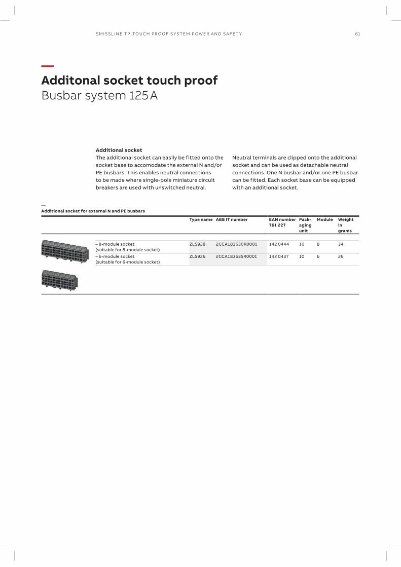
61SM ISSL I N E TP -TO U CH PR O O F S Y S TEM P OW ER A N D S A FE T Y
—Additonal socket touch proofBusbar system 125 A
Additional socketThe additional socket can easily be fitted onto the socket base to accomodate the external N and/or PE busbars. This enables neutral connections to be made where single-pole miniature circuit breakers are used with unswitched neutral.
Neutral terminals are clipped onto the ad ditional socket and can be used as detachable neutral connections. One N busbar and/or one PE busbar can be fitted. Each socket base can be equipped with an additional socket.
—Additional socket for external N and PE busbars
Type name ABB IT number EAN number761 227
Pack-agingunit
Module Weightingrams
– 8-module socket (suitable for 8-module socket)
ZLS928 2CCA183630R0001 142 0444 10 8 34
– 6-module socket (suitable for 6-module socket)
ZLS926 2CCA183635R0001 142 0437 10 6 26
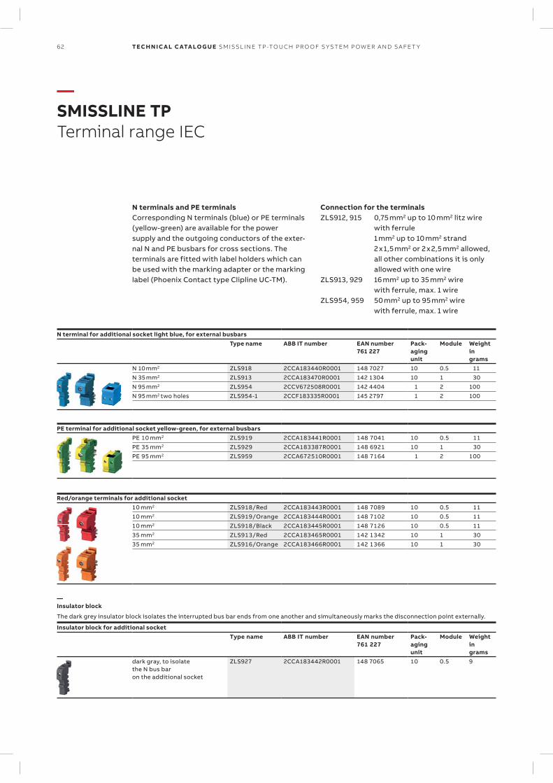
62 TECH N I C A L C ATA LO G U E SM ISSL I N E TP -TO U CH PR O O F S Y S TEM P OW ER A N D S A FE T Y
N terminal for additional socket light blue, for external busbarsType name ABB IT number EAN number
761 227Pack-agingunit
Module Weightingrams
N 10 mm2 ZLS918 2CCA183440R0001 148 7027 10 0.5 11N 35 mm2 ZLS913 2CCA183470R0001 142 1304 10 1 30N 95 mm2 ZLS954 2CCV672508R0001 142 4404 1 2 100N 95 mm2 two holes ZLS954-1 2CCF183335R0001 145 2797 1 2 100
PE terminal for additional socket yellow-green, for external busbarsPE 10 mm2 ZLS919 2CCA183441R0001 148 7041 10 0.5 11PE 35 mm2 ZLS929 2CCA183387R0001 148 6921 10 1 30PE 95 mm2 ZLS959 2CCA672510R0001 148 7164 1 2 100
Red/orange terminals for additional socket10 mm2 ZLS918/Red 2CCA183443R0001 148 7089 10 0.5 1110 mm2 ZLS919/Orange 2CCA183444R0001 148 7102 10 0.5 1110 mm2 ZLS918/Black 2CCA183445R0001 148 7126 10 0.5 1135 mm2 ZLS913/Red 2CCA183465R0001 142 1342 10 1 3035 mm2 ZLS916/Orange 2CCA183466R0001 142 1366 10 1 30
—Insulator block
The dark grey insulator block isolates the interrupted bus bar ends from one another and simultaneously marks the disconnection point externally.
Insulator block for additional socketType name ABB IT number EAN number
761 227Pack-agingunit
Module Weightingrams
dark gray, to isolatethe N bus baron the additional socket
ZLS927 2CCA183442R0001 148 7065 10 0.5 9
—SMISSLINE TPTerminal range IEC
N terminals and PE terminalsCorresponding N terminals (blue) or PE terminals (yellow-green) are available for the power supply and the outgoing conductors of the exter-nal N and PE busbars for cross sections. The terminals are fitted with label holders which can be used with the marking adapter or the marking label (Phoenix Contact type Clipline UC-TM).
Connection for the terminalsZLS912, 915 0,75 mm2 up to 10 mm2 litz wire
with ferrule 1 mm2 up to 10 mm2 strand 2 x 1,5 mm2 or 2 x 2,5 mm2 allowed,
all other combinations it is only allowed with one wire
ZLS913, 929 16 mm2 up to 35 mm2 wire with ferrule, max. 1 wire
ZLS954, 959 50 mm2 up to 95 mm2 wire with ferrule, max. 1 wire
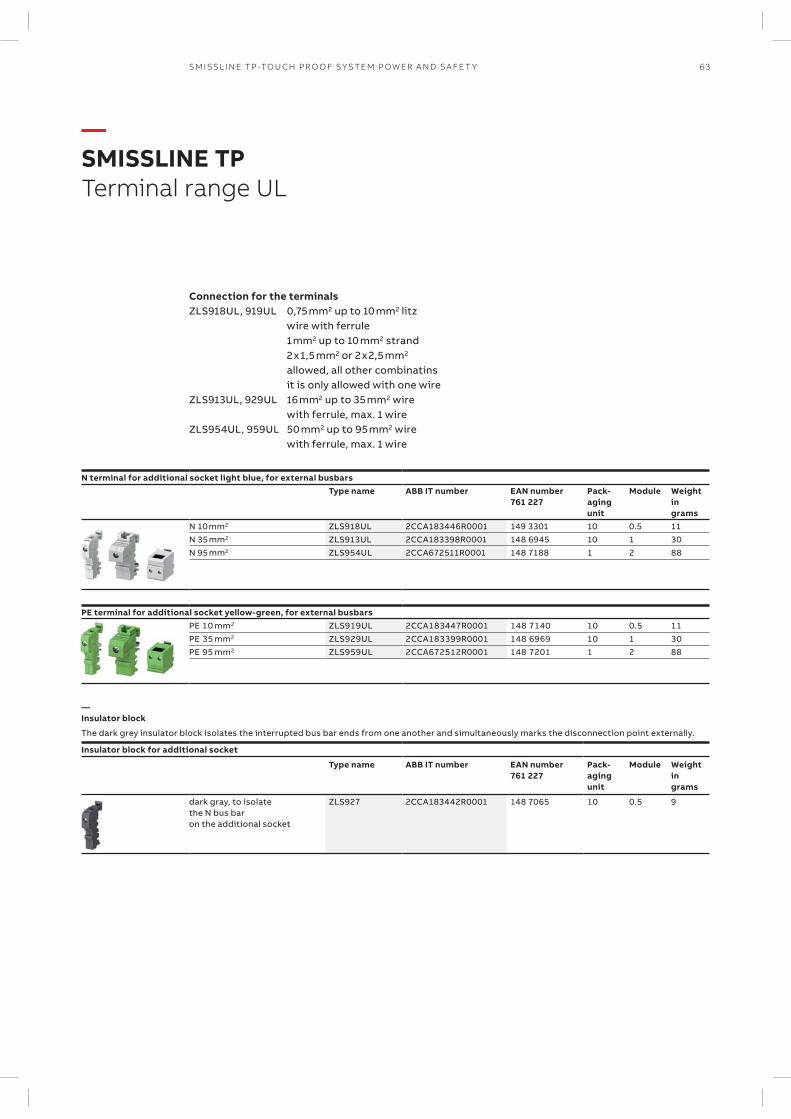
63SM ISSL I N E TP -TO U CH PR O O F S Y S TEM P OW ER A N D S A FE T Y
N terminal for additional socket light blue, for external busbarsType name ABB IT number EAN number
761 227Pack-agingunit
Module Weightingrams
N 10 mm2 ZLS918UL 2CCA183446R0001 149 3301 10 0.5 11N 35 mm2 ZLS913UL 2CCA183398R0001 148 6945 10 1 30N 95 mm2 ZLS954UL 2CCA672511R0001 148 7188 1 2 88
PE terminal for additional socket yellow-green, for external busbarsPE 10 mm2 ZLS919UL 2CCA183447R0001 148 7140 10 0.5 11PE 35 mm2 ZLS929UL 2CCA183399R0001 148 6969 10 1 30PE 95 mm2 ZLS959UL 2CCA672512R0001 148 7201 1 2 88
—Insulator block
The dark grey insulator block isolates the interrupted bus bar ends from one another and simultaneously marks the disconnection point externally.
Insulator block for additional socket
Type name ABB IT number EAN number761 227
Pack-agingunit
Module Weightingrams
dark gray, to isolatethe N bus baron the additional socket
ZLS927 2CCA183442R0001 148 7065 10 0.5 9
—SMISSLINE TPTerminal range UL
Connection for the terminalsZLS918UL, 919UL 0,75 mm2 up to 10 mm2 litz wire with ferrule 1 mm2 up to 10 mm2 strand 2 x 1,5 mm2 or 2 x 2,5 mm2
allowed, all other com binatins it is only allowed with one wire
ZLS913UL, 929UL 16 mm2 up to 35 mm2 wire with ferrule, max. 1 wire
ZLS954UL, 959UL 50 mm2 up to 95 mm2 wire with ferrule, max. 1 wire
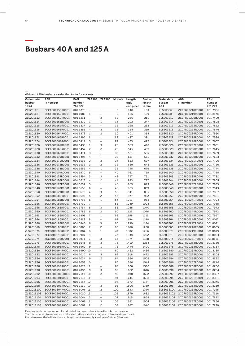
64 TECH N I C A L C ATA LO G U E SM ISSL I N E TP -TO U CH PR O O F S Y S TEM P OW ER A N D S A FE T Y
—Busbars 40 A and 125 A
—40 A and 125 A busbars / selection table for sockets
Order databusbar125 A
ABBIT number
EANnumber761 227
ZLS908 ZLS906 Module Lengthincl.end piece
Busbarlengthin mm
Order datebusbar40 A
ABBIT number
EANnumber761 227
ZLS201E6 2CCF800158R0001 001 6778 – 1 6 148 103 ZLS203E6 2CCF800218R0001 001 7966ZLS201E8 2CCF800159R0001 001 6983 1 – 8 186 139 ZLS203E8 2CCF800219R0001 001 8178ZLS201E12 2CCF800160R0001 001 6211 – 2 12 256 211 ZLS203E12 2CCF800220R0001 001 7409ZLS201E14 2CCF800161R0001 001 6310 1 1 14 292 247 ZLS203E14 2CCF800221R0001 001 7508ZLS201E16 2CCF800162R0001 001 6334 2 – 16 328 283 ZLS203E16 2CCF800222R0001 001 7522ZLS201E18 2CCF800163R0001 001 6358 – 3 18 364 319 ZLS203E18 2CCF800223R0001 001 7546ZLS201E20 2CCF800164R0001 001 6372 1 2 20 401 355 ZLS203E20 2CCF800224R0001 001 7560ZLS201E22 2CCF800165R0001 001 6396 2 1 22 437 391 ZLS203E22 2CCF800225R0001 001 7584ZLS201E24 2CCF800666R0001 001 6419 3 – 24 473 427 ZLS203E24 2CCF800226R0001 001 7607ZLS201E26 2CCF800167R0001 001 6433 1 3 26 509 463 ZLS203E26 2CCF800227R0001 001 7621ZLS201E28 2CCF800168R0001 001 6457 2 2 28 545 499 ZLS203E28 2CCF800228R0001 001 7645ZLS201E30 2CCF800169R0001 001 6471 3 1 30 581 535 ZLS203E30 2CCF800229R0001 001 7669ZLS201E32 2CCF800170R0001 001 6495 4 – 32 617 571 ZLS203E32 2CCF800230R0001 001 7683ZLS201E34 2CCF800171R0001 001 6518 2 3 34 653 607 ZLS203E34 2CCF800231R0001 001 7706ZLS201E36 2CCF800172R0001 001 6532 3 2 36 689 643 ZLS203E36 2CCF800232R0001 001 7720ZLS201E38 2CCF800173R0001 001 6556 4 1 38 725 679 ZLS203E38 2CCF800233R0001 001 7744ZLS201E40 2CCF800174R0001 001 6570 5 – 40 761 715 ZLS203E40 2CCF800234R0001 001 7768ZLS201E42 2CCF800175R0001 001 6594 3 3 42 797 751 ZLS203E42 2CCF800235R0001 001 7782ZLS201E44 2CCF800176R0001 001 6617 4 2 44 833 787 ZLS203E44 2CCF800236R0001 001 7805ZLS201E46 2CCF800177R0001 001 6631 5 1 46 869 823 ZLS203E46 2CCF800237R0001 001 7829ZLS201E48 2CCF800178R0001 001 6655 6 – 48 905 859 ZLS203E48 2CCF800238R0001 001 7843ZLS201E50 2CCF800179R0001 001 6679 4 3 50 941 895 ZLS203E50 2CCF800239R0001 001 7867ZLS201E52 2CCF800180R0001 001 6693 5 2 52 977 932 ZLS203E52 2CCF800240R0001 001 7881ZLS201E54 2CCF800181R0001 001 6716 6 1 54 1013 968 ZLS203E54 2CCF800241R0001 001 7904ZLS201E56 2CCF800182R0001 001 6730 7 – 56 1049 1004 ZLS203E56 2CCF800242R0001 001 7928ZLS201E58 2CCF800183R0001 001 6754 5 3 58 1085 1040 ZLS203E58 2CCF800243R0001 001 7942ZLS201E60 2CCF800184R0001 001 6785 6 2 60 1122 1076 ZLS203E60 2CCF800244R0001 001 7973ZLS201E62 2CCF800185R0001 001 6808 7 1 62 1158 1112 ZLS203E62 2CCF800245R0001 001 7997ZLS201E64 2CCF800186R0001 001 6822 8 – 64 1194 1148 ZLS203E64 2CCF800246R0001 001 8017ZLS201E66 2CCF800187R0001 001 6846 6 3 66 1230 1184 ZLS203E66 2CCF800247R0001 001 8031ZLS201E68 2CCF800188R0001 001 6860 7 2 68 1266 1220 ZLS203E68 2CCF800248R0001 001 8055ZLS201E70 2CCF800189R0001 001 6884 8 1 70 1302 1256 ZLS203E70 2CCF800249R0001 001 8079ZLS201E72 2CCF800190R0001 001 6907 9 – 72 1338 1292 ZLS203E72 2CCF800250R0001 001 8093ZLS201E74 2CCF800191R0001 001 6921 7 3 74 1374 1328 ZLS203E74 2CCF800251R0001 001 8116ZLS201E76 2CCF800192R0001 001 6945 8 2 76 1410 1364 ZLS203E76 2CCF800252R0001 001 8130ZLS201E78 2CCF800193R0001 001 6969 9 1 78 1446 1400 ZLS203E78 2CCF800253R0001 001 8154ZLS201E80 2CCF800194R0001 001 6990 10 – 80 1482 1436 ZLS203E80 2CCF800254R0001 001 8185ZLS201E82 2CCF800195R0001 001 7010 8 3 82 1518 1472 ZLS203E82 2CCF800255R0001 001 8208ZLS201E84 2CCF800196R0001 001 7034 9 2 84 1554 1508 ZLS203E84 2CCF800256R0001 001 8222ZLS201E86 2CCF800197R0001 001 7058 10 1 86 1590 1544 ZLS203E86 2CCF800257R0001 001 8246ZLS201E88 2CCF800198R0001 001 7072 11 – 88 1626 1580 ZLS203E88 2CCF800258R0001 001 8260ZLS201E90 2CCF800199R0001 001 7096 9 3 90 1662 1616 ZLS203E90 2CCF800259R0001 001 8284ZLS201E92 2CCF800200R0001 001 7119 10 2 92 1698 1652 ZLS203E92 2CCF800260R0001 001 8307ZLS201E94 2CCF800201R0001 001 7133 11 1 94 1734 1688 ZLS203E94 2CCF800261R0001 001 8321ZLS201E96 2CCF800202R0001 001 7157 12 – 96 1770 1724 ZLS203E96 2CCF800262R0001 001 8345ZLS201E98 2CCF800203R0001 001 7171 10 3 98 1806 1760 ZLS203E98 2CCF800263R0001 001 8369ZLS201E100 2CCF800204R0001 001 6006 11 2 100 1843 1796 ZLS203E100 2CCF800264R0001 001 7195ZLS201E102 2CCF800205R0001 001 6020 12 1 102 1879 1832 ZLS203E102 2CCF800265R0001 001 7218ZLS201E104 2CCF800206R0001 001 6044 13 – 104 1915 1868 ZLS203E104 2CCF800266R0001 001 7232ZLS201E106 2CCF800207R0001 001 6068 11 3 106 1951 1904 ZLS203E106 2CCF800267R0001 001 7256ZLS201E108 2CCF800208R0001 001 6082 12 2 108 1987 1940 ZLS203E108 2CCF800268R0001 001 7270
Planning for the incorporation of feeder block and spare places should be taken into account. The total lengths given above were calculated taking socket spacings and tolerances into account. For this reason, the indicated busbar length is not necessarily a multiple of 18 mm (1 Module).
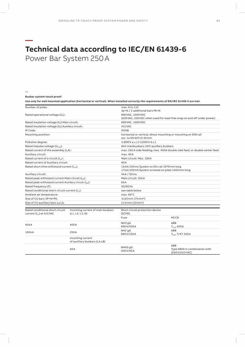
65SM ISSL I N E TP -TO U CH PR O O F S Y S TEM P OW ER A N D S A FE T Y
—Technical data according to IEC/EN 61439-6Power Bar System 250 A
—
Busbar system touch proof:
Use only for wall mounted application (horizontal or vertical). When installed correctly the requirements of EN/IEC 61439-2 are met.
Number of poles: max. 6 to 1103p+N / 2 additional bars PE+N
Rated operational voltage (Ue): 690 VAC, 1000 VDC(400 VAC, 250 VDC when used for load-free snap on and off under power)
Rated insulation voltage (Ui) Main circuit: 690 VAC, 1000 VDCRated insulation voltage (Ui) Auxilary circuit: 415 VACIP Code: IP20B Mounting position: horizontal or vertical, direct mounting or mounting on DIN rail
acc. to EN 60715 35 mmPollution degree: 3 (690 V a.c.) 2 (1000 V d.c.)Rated impulse voltage (Uimp): 8 kV mainbusbars; 6 KV auxillary busbarsRated current of the assembly (InA) : max. 250 A side feeding; max. 400A double side feed, or double center feedAuxiliary circuit: max. 40 ARated current of a circuit (Inc) : Main circuit: Max. 100 ARated current of Auxiliary circuit: 40 ARated short-time withstand current (Icw): 15 kA/100 ms System on Din rail 1979 mm long
17 kA/100 mS System screwed on plate 1400 mm longAuxiliary circuit: 4 kA / 50 msRated peak withstand current Main circuit (Ipk): Main circuit: 30 kARated peak withstand current Auxilary circuit (Ipk): 6 kARated frequency (f): 50/60 HzRated conditional short-circuit current (Icc): see table belowAmbient air temperature: max. 60°CSize of CU bars 3P+N+PE: 3 x25 mm (75 mm2)Size of CU auxiliary bars La Lb: 2 x 5 mm (10 mm2)
Rated conditional short-circuit current (Icc) at 415 VAC
Incoming current of main busbars (L1, L2, L3, N)
Short circuit protection device (SCPD)Fuse MCCB
40 kA 400 ANH3 gG 690 V/400 A
ABB Tmax 400 A
100 kA 250 ANH2 gG 690 V/250 A
ABB Tmax T/XT 250 A
Incoming current of auxiliary busbars (LA LB)
40 ANH00 gG 500 V/40 A
ABB Type S800 in combination with (240 V/415 V AC)

66 TECH N I C A L C ATA LO G U E SM ISSL I N E TP -TO U CH PR O O F S Y S TEM P OW ER A N D S A FE T Y
—Starter 3LPower Bar System 250 A
—Starter Pack 3L: L1, L2, L3 included socket end piece
Solutions available
Type name
ABB IT number
EAN number 761 227
Pack unit
Moduls (1 PLE 18mm)
Weight in grams
Starter Pack 3L PLE 30 ZLSP950E30-3L 2CCF212200A0001 148 8246 1 30PLE-3L 1755
Starter Pack 3L PLE 32 ZLSP950E32-3L 2CCF212201A0001 148 8260 1 32PLE-3L 1863
Starter Pack 3L PLE 34 ZLSP950E34-3L 2CCF212202A0001 148 8284 1 34PLE-3L 1981
Starter Pack 3L PLE 36 ZLSP950E36-3L 2CCF212203A0001 148 8307 1 36PLE-3L 2088
Starter Pack 3L PLE 38 ZLSP950E38-3L 2CCF212204A0001 148 8321 1 38PLE-3L 2195
Starter Pack 3L PLE 40 ZLSP950E40-3L 2CCF212205A0001 148 8345 1 40PLE-3L 2303
Starter Pack 3L PLE 42 ZLSP950E42-3L 2CCF212206A0001 148 8369 1 42PLE-3L 2421
Starter Pack 3L PLE 44 ZLSP950E44-3L 2CCF212207A0001 148 8383 1 44PLE-3L 2528
Starter Pack 3L PLE 46 ZLSP950E46-3L 2CCF212208A0001 148 8406 1 46PLE-3L 2635
Starter Pack 3L PLE 48 ZLSP950E48-3L 2CCF212209A0001 148 8420 1 48PLE-3L 2742
Starter Pack 3L PLE 50 ZLSP950E50-3L 2CCF212210A0001 148 8444 1 50PLE-3L 2861
Starter Pack 3L PLE 52 ZLSP950E52-3L 2CCF212211A0001 148 8468 1 52PLE-3L 2968
Starter Pack 3L PLE 54 ZLSP950E54-3L 2CCF212212A0001 148 8482 1 54PLE-3L 3075
Starter Pack 3L PLE 56 ZLSP950E56-3L 2CCF212213A0001 148 8505 1 56PLE-3L 3182
Starter Pack 3L PLE 58 ZLSP950E58-3L 2CCF212214A0001 148 8529 1 58PLE-3L 3301
Starter Pack 3L PLE 60 ZLSP950E60-3L 2CCF212215A0001 148 8543 1 60PLE-3L 3408
Starter Pack 3L PLE 62 ZLSP950E62-3L 2CCF212216A0001 148 8567 1 62PLE-3L 3515
Starter Pack 3L PLE 64 ZLSP950E64-3L 2CCF212217A0001 148 8581 1 64PLE-3L 3622
Starter Pack 3L PLE 66 ZLSP950E66-3L 2CCF212218A0001 148 8604 1 66PLE-3L 3741
Starter Pack 3L PLE 68 ZLSP950E68-3L 2CCF212219A0001 148 8628 1 68PLE-3L 3848
Starter Pack 3L PLE 70 ZLSP950E70-3L 2CCF212220A0001 148 8642 1 70PLE-3L 3955
Starter Pack 3L PLE 72 ZLSP950E72-3L 2CCF212221A0001 148 8666 1 72PLE-3L 4062
Starter Pack 3L PLE 74 ZLSP950E74-3L 2CCF212222A0001 148 8680 1 74PLE-3L 4180
Starter Pack 3L PLE 76 ZLSP950E76-3L 2CCF212223A0001 148 8703 1 76PLE-3L 4288
Starter Pack 3L PLE 78 ZLSP950E78-3L 2CCF212224A0001 148 8727 1 78PLE-3L 4395
Starter Pack 3L PLE 80 ZLSP950E80-3L 2CCF212225A0001 148 8741 1 80PLE-3L 4502
Starter Pack 3L PLE 82 ZLSP950E82-3L 2CCF212226A0001 148 8765 1 82PLE-3L 4620
Starter Pack 3L PLE 84 ZLSP950E84-3L 2CCF212227A0001 148 8789 1 84PLE-3L 4728
Starter Pack 3L PLE 86 ZLSP950E86-3L 2CCF212228A0001 148 8802 1 86PLE-3L 4835
Starter Pack 3L PLE 88 ZLSP950E88-3L 2CCF212229A0001 148 8826 1 88PLE-3L 4942
Starter Pack 3L PLE 90 ZLSP950E90-3L 2CCF212230A0001 148 8840 1 90PLE-3L 5060
Starter Pack 3L PLE 92 ZLSP950E92-3L 2CCF212231A0001 148 8864 1 92PLE-3L 5167
Starter Pack 3L PLE 94 ZLSP950E94-3L 2CCF212232A0001 148 8888 1 94PLE-3L 5275
Starter Pack 3L PLE 96 ZLSP950E96-3L 2CCF212233A0001 148 8901 1 96PLE-3L 5382
Starter Pack 3L PLE 98 ZLSP950E98-3L 2CCF212234A0001 148 8925 1 98PLE-3L 5500
Starter Pack 3L PLE 100 ZLSP950E100-3L 2CCF212235A0001 148 8949 1 100PLE-3L 5607
Starter Pack 3L PLE 102 ZLSP950E102-3L 2CCF212236A0001 148 8963 1 102PLE-3L 5715
Starter Pack 3L PLE 104 ZLSP950E104-3L 2CCF212237A0001 148 8987 1 104PLE-3L 5822
Starter Pack 3L PLE 106 ZLSP950E106-3L 2CCF212238A0001 148 9007 1 106PLE-3L 5940
Starter Pack 3L PLE 108 ZLSP950E108-3L 2CCF212239A0001 148 9021 1 108PLE-3L 6047
Starter Pack 3L PLE 110 ZLSP950E110-3L 2CCF212240A0001 148 9045 1 110PLE-3L 6121
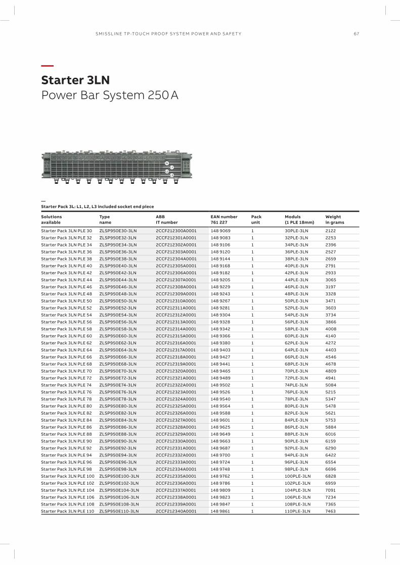
67SM ISSL I N E TP -TO U CH PR O O F S Y S TEM P OW ER A N D S A FE T Y
—Starter 3LNPower Bar System 250 A
—Starter Pack 3L: L1, L2, L3 included socket end piece
Solutions available
Type name
ABB IT number
EAN number 761 227
Pack unit
Moduls (1 PLE 18mm)
Weight in grams
Starter Pack 3LN PLE 30 ZLSP950E30-3LN 2CCF212300A0001 148 9069 1 30PLE-3LN 2122
Starter Pack 3LN PLE 32 ZLSP950E32-3LN 2CCF212301A0001 148 9083 1 32PLE-3LN 2253
Starter Pack 3LN PLE 34 ZLSP950E34-3LN 2CCF212302A0001 148 9106 1 34PLE-3LN 2396
Starter Pack 3LN PLE 36 ZLSP950E36-3LN 2CCF212303A0001 148 9120 1 36PLE-3LN 2527
Starter Pack 3LN PLE 38 ZLSP950E38-3LN 2CCF212304A0001 148 9144 1 38PLE-3LN 2659
Starter Pack 3LN PLE 40 ZLSP950E40-3LN 2CCF212305A0001 148 9168 1 40PLE-3LN 2791
Starter Pack 3LN PLE 42 ZLSP950E42-3LN 2CCF212306A0001 148 9182 1 42PLE-3LN 2933
Starter Pack 3LN PLE 44 ZLSP950E44-3LN 2CCF212307A0001 148 9205 1 44PLE-3LN 3065
Starter Pack 3LN PLE 46 ZLSP950E46-3LN 2CCF212308A0001 148 9229 1 46PLE-3LN 3197
Starter Pack 3LN PLE 48 ZLSP950E48-3LN 2CCF212309A0001 148 9243 1 48PLE-3LN 3328
Starter Pack 3LN PLE 50 ZLSP950E50-3LN 2CCF212310A0001 148 9267 1 50PLE-3LN 3471
Starter Pack 3LN PLE 52 ZLSP950E52-3LN 2CCF212311A0001 148 9281 1 52PLE-3LN 3603
Starter Pack 3LN PLE 54 ZLSP950E54-3LN 2CCF212312A0001 148 9304 1 54PLE-3LN 3734
Starter Pack 3LN PLE 56 ZLSP950E56-3LN 2CCF212313A0001 148 9328 1 56PLE-3LN 3866
Starter Pack 3LN PLE 58 ZLSP950E58-3LN 2CCF212314A0001 148 9342 1 58PLE-3LN 4008
Starter Pack 3LN PLE 60 ZLSP950E60-3LN 2CCF212315A0001 148 9366 1 60PLE-3LN 4140
Starter Pack 3LN PLE 62 ZLSP950E62-3LN 2CCF212316A0001 148 9380 1 62PLE-3LN 4272
Starter Pack 3LN PLE 64 ZLSP950E64-3LN 2CCF212317A0001 148 9403 1 64PLE-3LN 4403
Starter Pack 3LN PLE 66 ZLSP950E66-3LN 2CCF212318A0001 148 9427 1 66PLE-3LN 4546
Starter Pack 3LN PLE 68 ZLSP950E68-3LN 2CCF212319A0001 148 9441 1 68PLE-3LN 4678
Starter Pack 3LN PLE 70 ZLSP950E70-3LN 2CCF212320A0001 148 9465 1 70PLE-3LN 4809
Starter Pack 3LN PLE 72 ZLSP950E72-3LN 2CCF212321A0001 148 9489 1 72PLE-3LN 4941
Starter Pack 3LN PLE 74 ZLSP950E74-3LN 2CCF212322A0001 148 9502 1 74PLE-3LN 5084
Starter Pack 3LN PLE 76 ZLSP950E76-3LN 2CCF212323A0001 148 9526 1 76PLE-3LN 5215
Starter Pack 3LN PLE 78 ZLSP950E78-3LN 2CCF212324A0001 148 9540 1 78PLE-3LN 5347
Starter Pack 3LN PLE 80 ZLSP950E80-3LN 2CCF212325A0001 148 9564 1 80PLE-3LN 5478
Starter Pack 3LN PLE 82 ZLSP950E82-3LN 2CCF212326A0001 148 9588 1 82PLE-3LN 5621
Starter Pack 3LN PLE 84 ZLSP950E84-3LN 2CCF212327A0001 148 9601 1 84PLE-3LN 5753
Starter Pack 3LN PLE 86 ZLSP950E86-3LN 2CCF212328A0001 148 9625 1 86PLE-3LN 5884
Starter Pack 3LN PLE 88 ZLSP950E88-3LN 2CCF212329A0001 148 9649 1 88PLE-3LN 6016
Starter Pack 3LN PLE 90 ZLSP950E90-3LN 2CCF212330A0001 148 9663 1 90PLE-3LN 6159
Starter Pack 3LN PLE 92 ZLSP950E92-3LN 2CCF212331A0001 148 9687 1 92PLE-3LN 6290
Starter Pack 3LN PLE 94 ZLSP950E94-3LN 2CCF212332A0001 148 9700 1 94PLE-3LN 6422
Starter Pack 3LN PLE 96 ZLSP950E96-3LN 2CCF212333A0001 148 9724 1 96PLE-3LN 6554
Starter Pack 3LN PLE 98 ZLSP950E98-3LN 2CCF212334A0001 148 9748 1 98PLE-3LN 6696
Starter Pack 3LN PLE 100 ZLSP950E100-3LN 2CCF212335A0001 148 9762 1 100PLE-3LN 6828
Starter Pack 3LN PLE 102 ZLSP950E102-3LN 2CCF212336A0001 148 9786 1 102PLE-3LN 6959
Starter Pack 3LN PLE 104 ZLSP950E104-3LN 2CCF212337A0001 148 9809 1 104PLE-3LN 7091
Starter Pack 3LN PLE 106 ZLSP950E106-3LN 2CCF212338A0001 148 9823 1 106PLE-3LN 7234
Starter Pack 3LN PLE 108 ZLSP950E108-3LN 2CCF212339A0001 148 9847 1 108PLE-3LN 7365
Starter Pack 3LN PLE 110 ZLSP950E110-3LN 2CCF212340A0001 148 9861 1 110PLE-3LN 7463
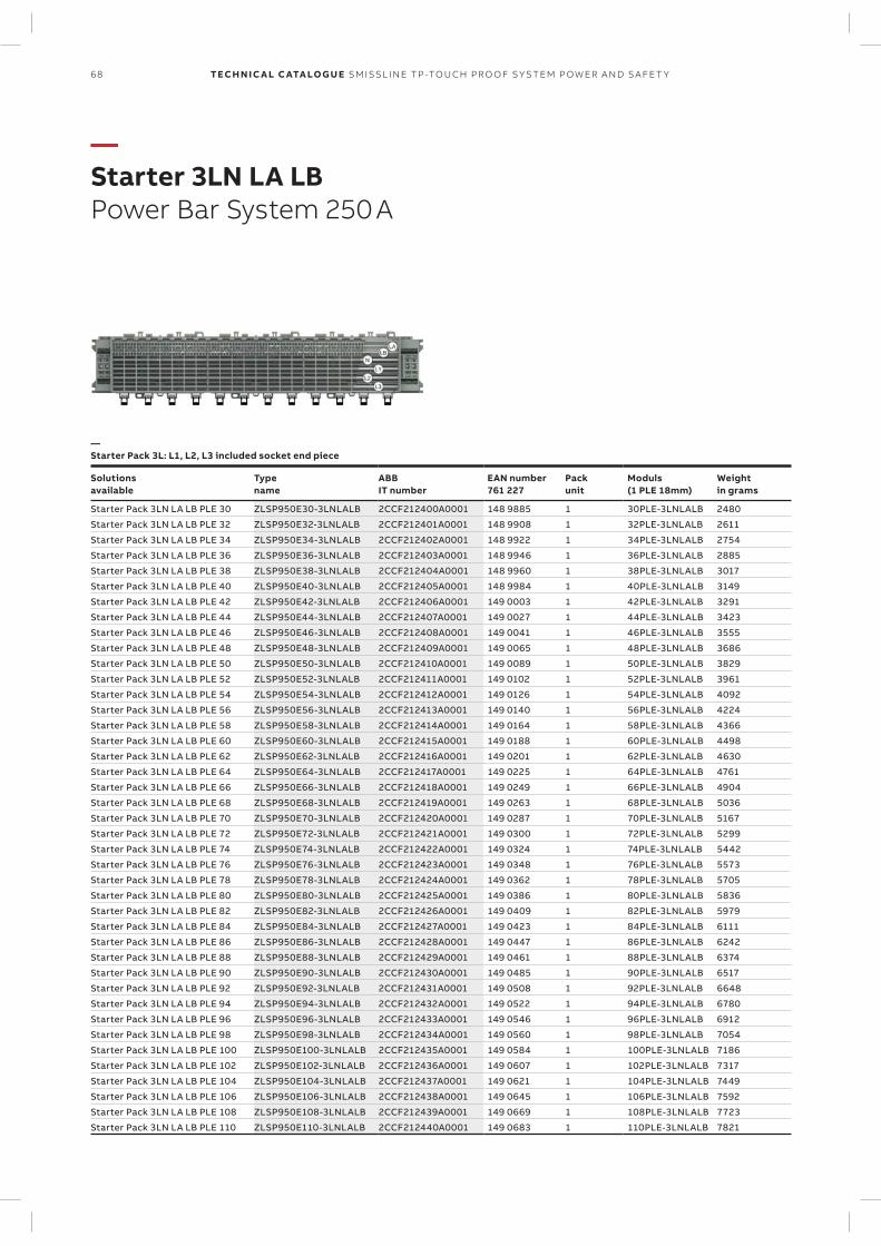
68 TECH N I C A L C ATA LO G U E SM ISSL I N E TP -TO U CH PR O O F S Y S TEM P OW ER A N D S A FE T Y
—Starter 3LN LA LBPower Bar System 250 A
—Starter Pack 3L: L1, L2, L3 included socket end piece
Solutions available
Type name
ABB IT number
EAN number 761 227
Pack unit
Moduls (1 PLE 18mm)
Weight in grams
Starter Pack 3LN LA LB PLE 30 ZLSP950E30-3LNLALB 2CCF212400A0001 148 9885 1 30PLE-3LNLALB 2480
Starter Pack 3LN LA LB PLE 32 ZLSP950E32-3LNLALB 2CCF212401A0001 148 9908 1 32PLE-3LNLALB 2611
Starter Pack 3LN LA LB PLE 34 ZLSP950E34-3LNLALB 2CCF212402A0001 148 9922 1 34PLE-3LNLALB 2754
Starter Pack 3LN LA LB PLE 36 ZLSP950E36-3LNLALB 2CCF212403A0001 148 9946 1 36PLE-3LNLALB 2885
Starter Pack 3LN LA LB PLE 38 ZLSP950E38-3LNLALB 2CCF212404A0001 148 9960 1 38PLE-3LNLALB 3017
Starter Pack 3LN LA LB PLE 40 ZLSP950E40-3LNLALB 2CCF212405A0001 148 9984 1 40PLE-3LNLALB 3149
Starter Pack 3LN LA LB PLE 42 ZLSP950E42-3LNLALB 2CCF212406A0001 149 0003 1 42PLE-3LNLALB 3291
Starter Pack 3LN LA LB PLE 44 ZLSP950E44-3LNLALB 2CCF212407A0001 149 0027 1 44PLE-3LNLALB 3423
Starter Pack 3LN LA LB PLE 46 ZLSP950E46-3LNLALB 2CCF212408A0001 149 0041 1 46PLE-3LNLALB 3555
Starter Pack 3LN LA LB PLE 48 ZLSP950E48-3LNLALB 2CCF212409A0001 149 0065 1 48PLE-3LNLALB 3686
Starter Pack 3LN LA LB PLE 50 ZLSP950E50-3LNLALB 2CCF212410A0001 149 0089 1 50PLE-3LNLALB 3829
Starter Pack 3LN LA LB PLE 52 ZLSP950E52-3LNLALB 2CCF212411A0001 149 0102 1 52PLE-3LNLALB 3961
Starter Pack 3LN LA LB PLE 54 ZLSP950E54-3LNLALB 2CCF212412A0001 149 0126 1 54PLE-3LNLALB 4092
Starter Pack 3LN LA LB PLE 56 ZLSP950E56-3LNLALB 2CCF212413A0001 149 0140 1 56PLE-3LNLALB 4224
Starter Pack 3LN LA LB PLE 58 ZLSP950E58-3LNLALB 2CCF212414A0001 149 0164 1 58PLE-3LNLALB 4366
Starter Pack 3LN LA LB PLE 60 ZLSP950E60-3LNLALB 2CCF212415A0001 149 0188 1 60PLE-3LNLALB 4498
Starter Pack 3LN LA LB PLE 62 ZLSP950E62-3LNLALB 2CCF212416A0001 149 0201 1 62PLE-3LNLALB 4630
Starter Pack 3LN LA LB PLE 64 ZLSP950E64-3LNLALB 2CCF212417A0001 149 0225 1 64PLE-3LNLALB 4761
Starter Pack 3LN LA LB PLE 66 ZLSP950E66-3LNLALB 2CCF212418A0001 149 0249 1 66PLE-3LNLALB 4904
Starter Pack 3LN LA LB PLE 68 ZLSP950E68-3LNLALB 2CCF212419A0001 149 0263 1 68PLE-3LNLALB 5036
Starter Pack 3LN LA LB PLE 70 ZLSP950E70-3LNLALB 2CCF212420A0001 149 0287 1 70PLE-3LNLALB 5167
Starter Pack 3LN LA LB PLE 72 ZLSP950E72-3LNLALB 2CCF212421A0001 149 0300 1 72PLE-3LNLALB 5299
Starter Pack 3LN LA LB PLE 74 ZLSP950E74-3LNLALB 2CCF212422A0001 149 0324 1 74PLE-3LNLALB 5442
Starter Pack 3LN LA LB PLE 76 ZLSP950E76-3LNLALB 2CCF212423A0001 149 0348 1 76PLE-3LNLALB 5573
Starter Pack 3LN LA LB PLE 78 ZLSP950E78-3LNLALB 2CCF212424A0001 149 0362 1 78PLE-3LNLALB 5705
Starter Pack 3LN LA LB PLE 80 ZLSP950E80-3LNLALB 2CCF212425A0001 149 0386 1 80PLE-3LNLALB 5836
Starter Pack 3LN LA LB PLE 82 ZLSP950E82-3LNLALB 2CCF212426A0001 149 0409 1 82PLE-3LNLALB 5979
Starter Pack 3LN LA LB PLE 84 ZLSP950E84-3LNLALB 2CCF212427A0001 149 0423 1 84PLE-3LNLALB 6111
Starter Pack 3LN LA LB PLE 86 ZLSP950E86-3LNLALB 2CCF212428A0001 149 0447 1 86PLE-3LNLALB 6242
Starter Pack 3LN LA LB PLE 88 ZLSP950E88-3LNLALB 2CCF212429A0001 149 0461 1 88PLE-3LNLALB 6374
Starter Pack 3LN LA LB PLE 90 ZLSP950E90-3LNLALB 2CCF212430A0001 149 0485 1 90PLE-3LNLALB 6517
Starter Pack 3LN LA LB PLE 92 ZLSP950E92-3LNLALB 2CCF212431A0001 149 0508 1 92PLE-3LNLALB 6648
Starter Pack 3LN LA LB PLE 94 ZLSP950E94-3LNLALB 2CCF212432A0001 149 0522 1 94PLE-3LNLALB 6780
Starter Pack 3LN LA LB PLE 96 ZLSP950E96-3LNLALB 2CCF212433A0001 149 0546 1 96PLE-3LNLALB 6912
Starter Pack 3LN LA LB PLE 98 ZLSP950E98-3LNLALB 2CCF212434A0001 149 0560 1 98PLE-3LNLALB 7054
Starter Pack 3LN LA LB PLE 100 ZLSP950E100-3LNLALB 2CCF212435A0001 149 0584 1 100PLE-3LNLALB 7186
Starter Pack 3LN LA LB PLE 102 ZLSP950E102-3LNLALB 2CCF212436A0001 149 0607 1 102PLE-3LNLALB 7317
Starter Pack 3LN LA LB PLE 104 ZLSP950E104-3LNLALB 2CCF212437A0001 149 0621 1 104PLE-3LNLALB 7449
Starter Pack 3LN LA LB PLE 106 ZLSP950E106-3LNLALB 2CCF212438A0001 149 0645 1 106PLE-3LNLALB 7592
Starter Pack 3LN LA LB PLE 108 ZLSP950E108-3LNLALB 2CCF212439A0001 149 0669 1 108PLE-3LNLALB 7723
Starter Pack 3LN LA LB PLE 110 ZLSP950E110-3LNLALB 2CCF212440A0001 149 0683 1 110PLE-3LNLALB 7821
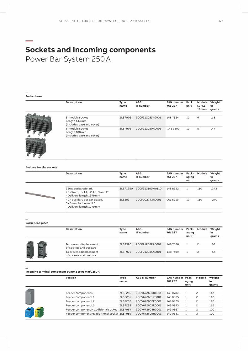
69SM ISSL I N E TP -TO U CH PR O O F S Y S TEM P OW ER A N D S A FE T Y
—Sockets and Incoming componentsPower Bar System 250 A
—Socket base
Description Type name
ABB IT number
EAN number 761 227
Pack unit
Moduls (1 PLE 18mm)
Weight in grams
8-module socket Length 144 mm (includes base and cover)
ZLSP906 2CCF212053A0001 148 7324 10 6 113
6-module socket Length 108 mm (includes base and cover)
ZLSP908 2CCF212050A0001 148 7300 10 8 147
—Busbars for the sockets
Description Type name
ABB IT number
EAN number 761 227
Pack- aging unit
Module Weight in grams
250 A busbar plated, 25 x 3 mm, for L1, L2, L3, N and PE – Delivery length 1979 mm
ZLSP1250 2CCF212100M0110 148 8222 1 110 1343
40 A auxiliary busbar plated, 5 x 2 mm, for LA und LB – Delivery length 1979 mm
ZLS202 2CCF002773R0001 001 5719 10 110 240
—Socket end piece
Description Type name
ABB IT number
EAN number 761 227
Pack- aging unit
Module Weight in grams
To prevent displacement of sockets and busbars
ZLSP920 2CCF212082A0001 148 7386 1 2 103
To prevent displacement of sockets and busbars
ZLSP921 2CCF212085A0001 148 7409 1 2 54
—Incoming terminal component 10 mm2 to 95 mm2, 250 A
Version Typename
ABB IT number EAN number761 227
Pack-agingunit
Module Weightingrams
Feeder component N ZLSP250 2CCV672600R0001 149 0782 1 2 112Feeder component L1 ZLSP251 2CCV672601R0001 149 0805 1 2 112Feeder component L2 ZLSP252 2CCV672602R0001 149 0829 1 2 112Feeder component L3 ZLSP253 2CCV672603R0001 149 0843 1 2 112Feeder component N additional socket ZLSP954 2CCV672608R0001 149 0867 1 2 100Feeder component PE additional socket ZLSP959 2CCV672609R0001 149 0881 1 2 100
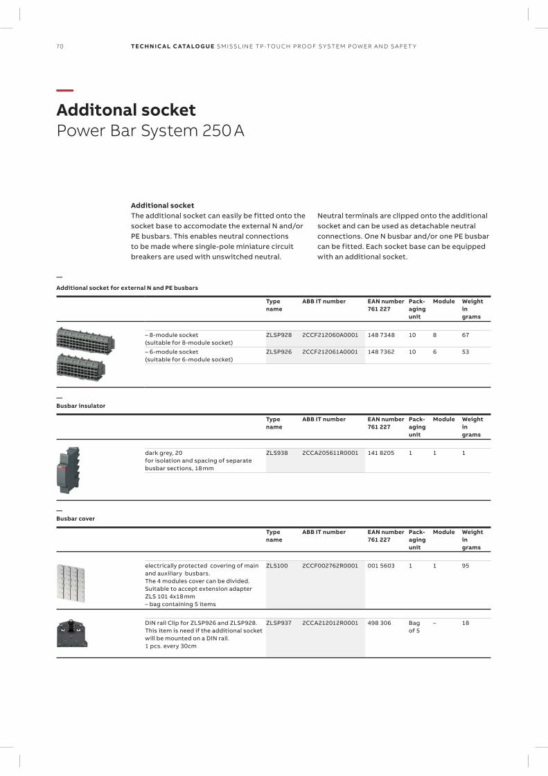
70 TECH N I C A L C ATA LO G U E SM ISSL I N E TP -TO U CH PR O O F S Y S TEM P OW ER A N D S A FE T Y
—Additonal socketPower Bar System 250 A
Additional socketThe additional socket can easily be fitted onto the socket base to accomodate the external N and/or PE busbars. This enables neutral connections to be made where single-pole miniature circuit breakers are used with unswitched neutral.
Neutral terminals are clipped onto the ad ditional socket and can be used as detachable neutral connections. One N busbar and/or one PE busbar can be fitted. Each socket base can be equipped with an additional socket.
—
Additional socket for external N and PE busbars
Typename
ABB IT number EAN number761 227
Pack-agingunit
Module Weightingrams
– 8-module socket (suitable for 8-module socket)
ZLSP928 2CCF212060A0001 148 7348 10 8 67
– 6-module socket (suitable for 6-module socket)
ZLSP926 2CCF212061A0001 148 7362 10 6 53
—Busbar insulator
Typename
ABB IT number EAN number761 227
Pack-agingunit
Module Weightingrams
dark grey, 20for isolation and spacing of separate busbar sections, 18 mm
ZLS938 2CCA205611R0001 141 8205 1 1 1
—Busbar cover
Typename
ABB IT number EAN number761 227
Pack-agingunit
Module Weightingrams
electrically protected covering of main and auxiliary busbars.The 4 modules cover can be divided. Suitable to accept extension adapter ZLS 101 4x18 mm– bag containing 5 items
ZLS100 2CCF002762R0001 001 5603 1 1 95
DIN rail Clip for ZLSP926 and ZLSP928. This item is need if the additional socket will be mounted on a DIN rail. 1 pcs. every 30cm
ZLSP937 2CCA212012R0001 498 306 Bag of 5
– 18
71SM ISSL I N E TP -TO U CH PR O O F S Y S TEM P OW ER A N D S A FE T Y
— Table of conteantsTechnical data
072 – 080 Busbar system
082 – 094 MCBs technical details
095 – 102 RCDs technical details
103 IS404 technical details
104 – 105 OVR technical details
106 – 108 Surge and lightning protection solutions
109 – 110 Auxiliary switches and signal contacts
111 Shunt trip for S400
112 – 121 CMS – Current Measurement System
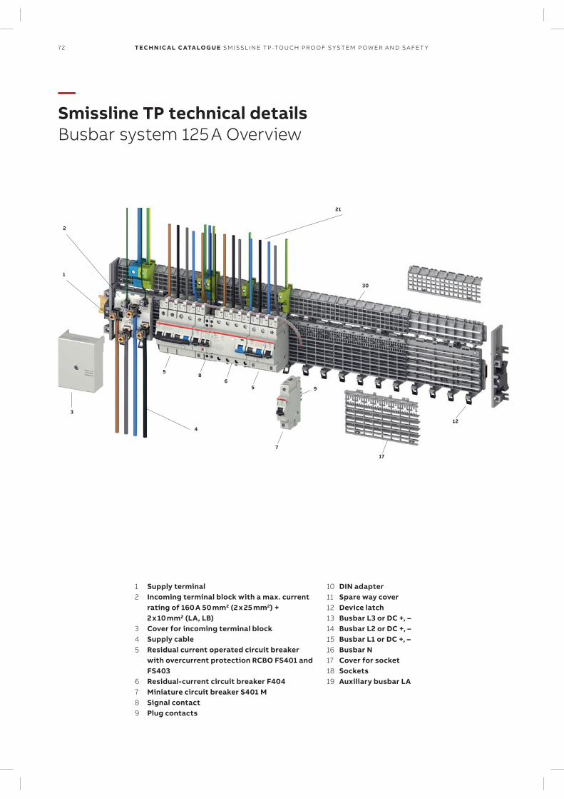
9
4
3
30
2
12
7
17
5
5
68
1
21
72 TECH N I C A L C ATA LO G U E SM ISSL I N E TP -TO U CH PR O O F S Y S TEM P OW ER A N D S A FE T Y
—Smissline TP technical detailsBusbar system 125 A Overview
1 Supply terminal2 Incoming terminal block with a max. current
rating of 160 A 50 mm2 (2 x 25 mm2) + 2 x 10 mm2 (LA, LB)
3 Cover for incoming terminal block4 Supply cable5 Residual current operated circuit breaker
with overcurrent protection RCBO FS401 and FS403
6 Residual-current circuit breaker F4047 Miniature circuit breaker S401 M8 Signal contact9 Plug contacts
10 DIN adapter11 Spare way cover12 Device latch13 Busbar L3 or DC +, –14 Busbar L2 or DC +, –15 Busbar L1 or DC +, –16 Busbar N17 Cover for socket18 Sockets19 Auxiliary busbar LA
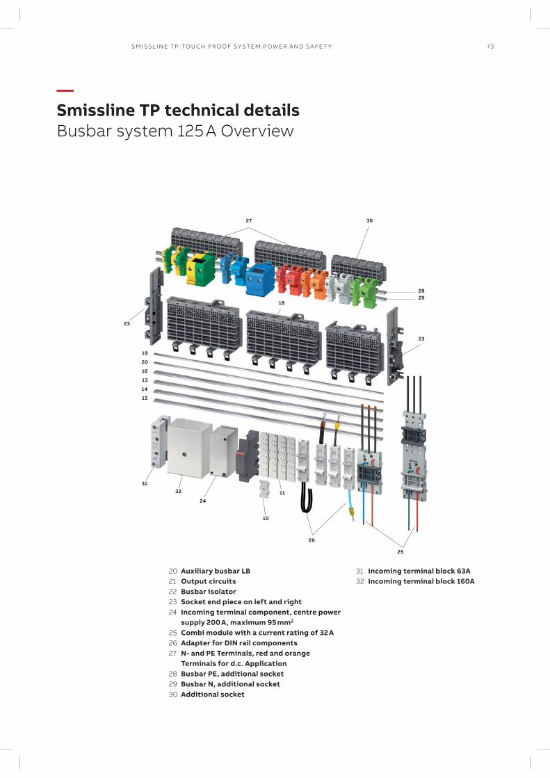
23
19
20
16
13
14
15
25
24
3132
10
11
18
23
26
2829
3027
73SM ISSL I N E TP -TO U CH PR O O F S Y S TEM P OW ER A N D S A FE T Y
—Smissline TP technical detailsBusbar system 125 A Overview
20 Auxiliary busbar LB21 Output circuits22 Busbar isolator23 Socket end piece on left and right24 Incoming terminal component, centre power
supply 200 A, maximum 95 mm2
25 Combi module with a current rating of 32 A26 Adapter for DIN rail components27 N- and PE Terminals, red and orange
Terminals for d.c. Application28 Busbar PE, additional socket29 Busbar N, additional socket30 Additional socket
31 Incoming terminal block 63A32 Incoming terminal block 160A
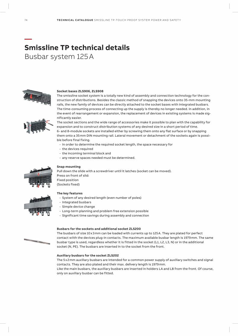
74 TECH N I C A L C ATA LO G U E SM ISSL I N E TP -TO U CH PR O O F S Y S TEM P OW ER A N D S A FE T Y
—Smissline TP technical detailsBusbar system 125 A
Socket bases ZLS906, ZLS908The smissline socket system is a totally new kind of assembly and connection technology for the con-struction of distributions. Besides the classic method of snapping the devices onto 35-mm mounting rails, the new family of devices can be directly attached to the socket bases with integrated busbars. The time-consuming process of connecting up the supply is thereby no longer needed. In addition, in the event of rearrangement or expansion, the replacement of devices in existing systems is made sig-nificantly easier.The socket sections and the wide range of accessories make it possible to plan with the capability for expansion and to construct distribution systems of any desired size in a short period of time.6- and 8-module sockets are installed either by screwing them onto any flat surface or by snapping them onto a 35 mm DIN mounting rail. Lateral movement or detachment of the sockets again is possi-ble before final fixing.
- In order to determine the required socket length, the space necessary for - the devices required - the incoming terminal block and - any reserve spaces needed must be determined.
Snap mountingPull down the slide with a screwdriver until it latches (socket can be moved).Press on front of slid:Fixed position(Sockets fixed)
The key features - System of any desired length (even number of poles) - Integrated busbars - Simple device change - Long-term planning and problem free extension possible - Significant time savings during assembly and connection
Busbars for the sockets and additional socket ZLS200The busbars of size 10 x 3 mm can be loaded with currents up to 125 A. They are plated for perfect contact wiith the devices plug-in contacts. The maximum available busbar length is 1979 mm. The same busbar type is used, regardless whether it is fitted in the socket (L1, L2, L3, N) or in the additional socket (N, PE). The busbars are inserted in to the socket from the front.
Auxiliary busbars for the socket ZLS202The 5 x 2 mm auxiliary busbars are intended for a common power supply of auxiliary switches and signal contacts. They are also plated and their max. delivery length is 1979 mm. Like the main busbars, the auxiliary busbars are inserted in holders LA and LB from the front. Of course, only on auxiliary busbar can be fitted.
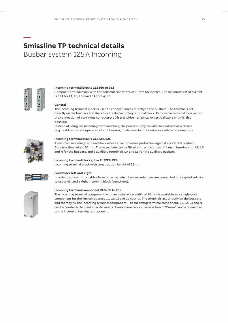
75SM ISSL I N E TP -TO U CH PR O O F S Y S TEM P OW ER A N D S A FE T Y
—Smissline TP technical detailsBusbar system 125 A Incoming
Incoming terminal blocks ZLS260 to 262Compact terminal block with the construction width of 18 mm for 2 poles. The maximum rated current is 63 A for L1, L2, L3N and 6 A for LA, LB.
GeneralThe incoming terminal block is used to connect cables directly to the busbars. The terminals act directly on the busbars and therefore fix the incoming terminal block. Removable terminal tops permit the connection of continous conductrors (risers) white horizontal or vertical cable entry is also possible. Instead of using the incoming terminal block, the power supply can also be realized via a device (e.g. residual current operated circuit breaker, miniature circuit breaker or switch disconnector). Incoming terminal blocks ZLS224, 225A standard incoming terminal block whose cover provides protection against accidental contact. Construction height 50 mm. The base plate can be fitted with a maximum of 4 main terminals L1, L2, L3 and N for the busbars, and 2 auxiliary termiinals LA and LB for the auxiliary busbars.
Incoming terminal blocks, low ZLS228, 229Incoming terminal block with construction height of 36 mm.
Feed block left and rightIn order to prevent the cables from crossing when two sockets rows are connected it is a good solution to use a left and a right incoming block (see photo).
Incoming terminal component ZLS250 to 255The incoming terminal component, with an installation width of 36 mm is available as a single-pole component for the line conductors L1, L2, L3 and as neutral. The terminals act directly on the busbars and thereby fix the incoming terminal component. The incoming terminal component, L1, L2, L3 and N can be combined to meet specific needs. A maximum cable cross-section of 95 mm2 can be connected to the incoming terminal component.
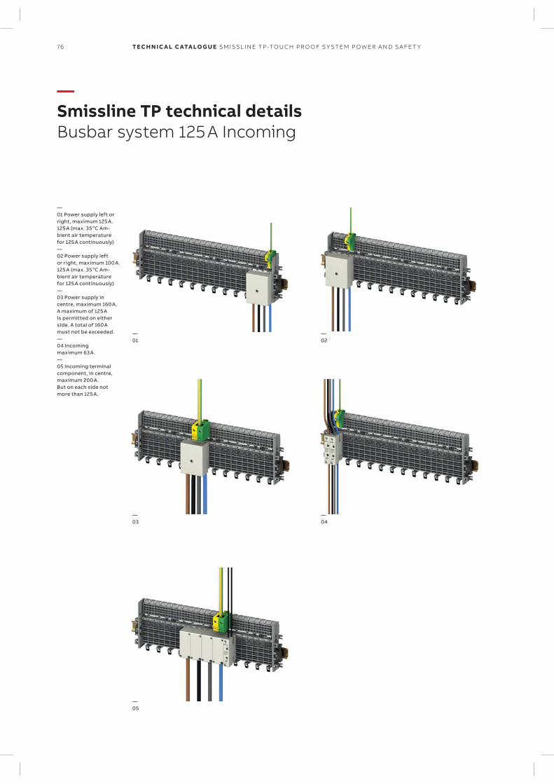
—01
—03
—05
—02
—04
76 TECH N I C A L C ATA LO G U E SM ISSL I N E TP -TO U CH PR O O F S Y S TEM P OW ER A N D S A FE T Y
—Smissline TP technical detailsBusbar system 125 A Incoming
—01 Power supply left or right, maximum 125 A.125 A (max. 35 °C Am-bient air temperature for 125 A continuously)—02 Power supply left or right, maximum 100 A.125 A (max. 35 °C Am-bient air temperature for 125 A continuously)—03 Power supply in centre, maximum 160 A.A maximum of 125 A is permitted on either side. A total of 160 A must not be exceeded.—04 Incoming maximum 63 A.—05 Incoming terminal component, in centre, maximum 200 A. But on each side not more than 125 A.
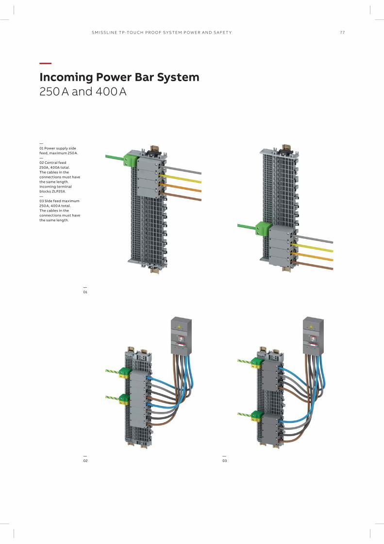
77SM ISSL I N E TP -TO U CH PR O O F S Y S TEM P OW ER A N D S A FE T Y
—Incoming Power Bar System250 A and 400 A
—01 Power supply side feed, maximum 250 A.—02 Central feed 250A, 400A total.The cables in the connections must have the same length. Incoming terminal blocks ZLP25X.—03 Side feed maximum 250 A, 400 A total. The cables in the connections must have the same length.
—02
—01
—03
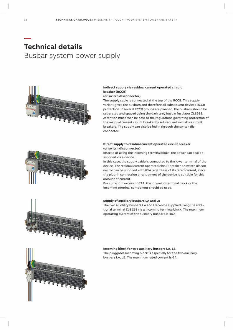
78 TECH N I C A L C ATA LO G U E SM ISSL I N E TP -TO U CH PR O O F S Y S TEM P OW ER A N D S A FE T Y
—Technical detailsBusbar system power supply
Indirect supply via residual current operated circuit breaker (RCCB) (or switch disconnector)The supply cable is connected at the top of the RCCB. This supply variant gives the busbars and therefore all subsequent devices RCCB protection. If several RCCB groups are planned, the busbars should be separated and spaced using the dark grey busbar insulator ZLS938. Attention must then be paid to the regulations governing protection of the residual current circuit breaker by subsequent miniature circuit breakers. The supply can also be fed in through the switch dis-connector.
Direct supply to residual current operated circuit breaker (or switch disconnector)Instead of using the incoming terminal block, the power can also be supplied via a device. In this case, the supply cable is connected to the lower terminal of the device. The residual current operated circuit breaker or switch discon-nector can be supplied with 63 A regardless of its rated current, since the plug-in connection arrangement of the device is suitable for this amount of current. For current in excess of 63 A, the incoming terminal block or the incoming terminal component should be used.
Supply of auxiliary busbars LA and LBThe two auxiliary busbars LA and LB can be supplied using the addi-tional terminal ZLS 233 via a incoming terminal block. The maximum operating current of the auxiliary busbars is 40 A.
Incoming block for two auxiliary busbars LA, LBThe pluggable incoming block is especially for the two auxiliary busbars LA, LB. The maximum rated current is 6 A.
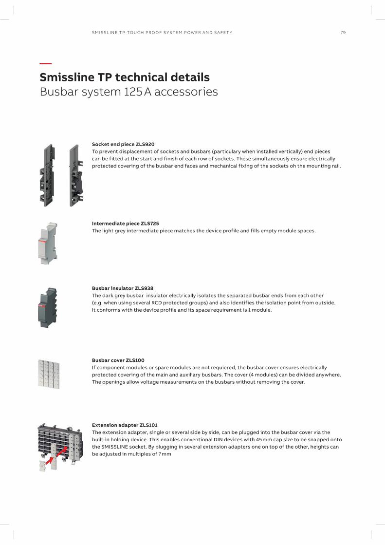
79SM ISSL I N E TP -TO U CH PR O O F S Y S TEM P OW ER A N D S A FE T Y
—Smissline TP technical detailsBusbar system 125 A accessories
Socket end piece ZLS920To prevent displacement of sockets and busbars (particulary when installed vertically) end pieces can be fitted at the start and finish of each row of sockets. These simultaneously ensure electrically protected covering of the busbar end faces and mechanical fixing of the sockets oh the mounting rail.
Intermediate piece ZLS725The light grey intermediate piece matches the device profile and fills empty module spaces.
Busbar insulator ZLS938The dark grey busbar insulator electrically isolates the separated busbar ends from each other (e.g. when using several RCD protected groups) and also identifies the isolation point from outside. It conforms with the device profile and its space requirement is 1 module.
Busbar cover ZLS100If component modules or spare modules are not requiered, the busbar cover ensures electrically protected covering of the main and auxiliary busbars. The cover (4 modules) can be divided anywhere. The openings allow voltage measurements on the busbars without removing the cover.
Extension adapter ZLS101The extension adapter, single or several side by side, can be plugged into the busbar cover via the built-in holding device. This enables conventional DIN devices with 45 mm cap size to be snapped onto the SMISSLINE socket. By plugging in several extension adapters one on top of the other, heights can be adjusted in multiples of 7 mm
80 TECH N I C A L C ATA LO G U E SM ISSL I N E TP -TO U CH PR O O F S Y S TEM P OW ER A N D S A FE T Y
—Definitions
Rated short-circuit breaking capacity Icn
According to EN 60898-1The maximum current which a switching device can switch off without damage at a rated opera-tional voltage and rated operational frequency. It is specified as an effective value.
Rated ultimate short-circuit breaking capacity Icu
According to EN 60947-2Ultimate short-circuit breaking capacity that a circuit breaker can switch off without damage at a rated operational voltage and rated operational frequency. It is specified as an effective value.
Rated service short-circuit breaking capacity Ics
According to EN 60947-2Service short-circuit breaking capacity that a cir-cuit breaker can switch off without damage at a rated operational voltage and rated operational frequency. It is specified as an effective value.
Rated insulation voltage Ui
The rated insulation voltage (Ui) is the voltage to which dielectric checks and creepage distances refer. The maximum rated operational voltage must not exceed its rated insulation voltage.
Rated impulse withstand voltage Uimp
Peak of a withstand voltage of a specified form and polarity with which the circuit can be loaded under specified test conditions without a break-down and to which clearances relate.The rated impulse withstand voltage must be equal to or greater than the values of the with-stand over-voltages (transient overvoltages) which occur in the system in which the device is used.
Rated short-time withstand current Icw
The rated short-time withstand current is the ef-fective value of the short-circuit current, as speci-fied by the manufacturer for this circuit, that the circuit can conduct without damage. Unless oth-erwise specified, a time of 1 s shall apply.
Rated conditional short-circuit current Icc
The rated conditional short-circuit current is the value of the prospective short-circuit current, as specified by the manufacturer, for a switching device combination that the latter can conduct during the total break time. The information about the specified short-circuit device must be given by the manufacturer.
Rated fused short-circuit current Icf
The rated fused short-circuit current is the condi-tional rated short-circuit current if the short-cir-cuit device is a fuse in accordance with IEC 60269 [IEV 441-17-21, modified].
Rated peak withstand current Ipk
The rated peak withstand current is the peak value of the withstand current of the circuit of a combination of switching devices, as specified by the manufacturer.
Back-up protectionAssignment of two overcurrent protective devices in series, where the protective device, generally but not necessarily on the supply side, effects the overcurrent protection with or without the assistance of the other protective device and prevents excessive stress on the latter [IEC 60947-1, definition 2.5.24].
Total selectivityOvercurrent discrimination where, in the pres-ence of two overcurrent protective devices in series, the protective device on the load side effects the protection without causing the other protective device to operate [IEC 60947-2, definition 2.17.2].
Partial selectivityOvercurrent discrimination where, in the pres-ence of two overcurrent protective devices in series, the protective device on the load side effects the protection up to a given level of overcurrent, without causing the other protective device to operate [IEC 60947-2, defini-tion 2.17.3].
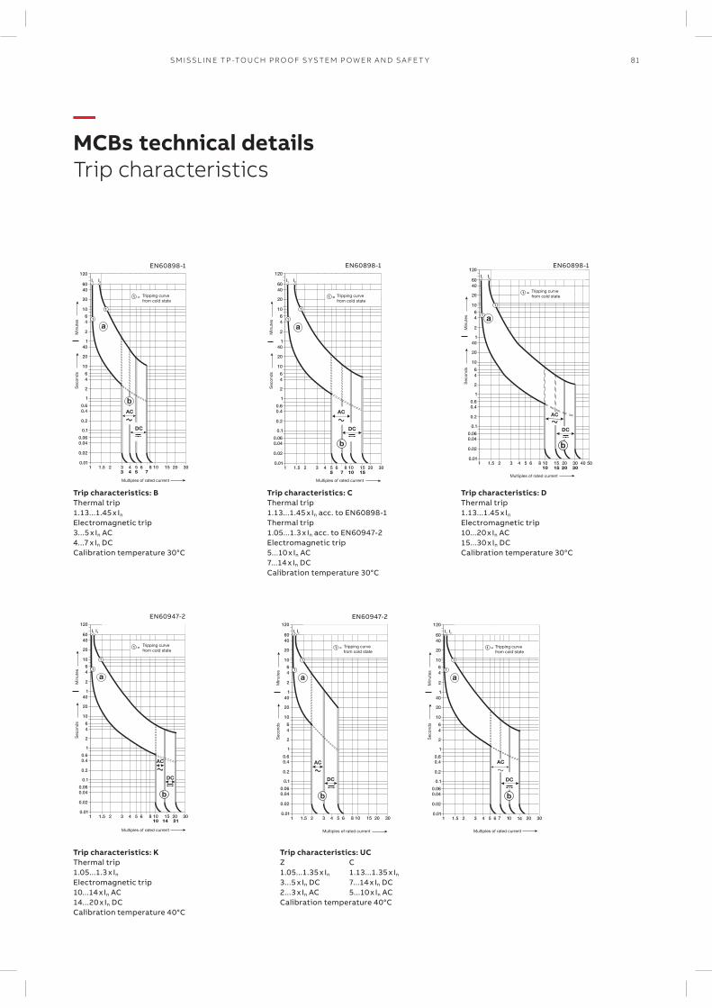
Sec
ond
s
Multiples of rated current
Min
utes
Tripping curve from cold state
Sec
ond
s
Multiples of rated current
Min
utes
Tripping curve from cold state
EN60898-1
EN60947-2 EN60947-2
EN60898-1 EN60898-1
Sec
ond
s
Multiples of rated current
Min
utes
Tripping curve from cold state
Sec
ond
s
Multiples of rated current
Min
utes
Tripping curve from cold state
Multiples of rated current
Sec
ond
sM
inut
es
Tripping curve from cold state
Multiples of rated current
Sec
ond
sM
inut
es
Tripping curve from cold state
81SM ISSL I N E TP -TO U CH PR O O F S Y S TEM P OW ER A N D S A FE T Y
—MCBs technical detailsTrip characteristics
Trip characteristics: BThermal trip 1.13...1.45 x In
Electromagnetic trip3...5 x In AC4...7 x In DCCalibration temperature 30°C
Trip characteristics: CThermal trip 1.13...1.45 x In acc. to EN60898-1Thermal trip 1.05...1.3 x In acc. to EN60947-2Electromagnetic trip5...10 x In AC7...14 x In DCCalibration temperature 30°C
Trip characteristics: DThermal trip 1.13...1.45 x In
Electromagnetic trip10...20 x In AC15...30 x In DCCalibration temperature 30°C
Trip characteristics: KThermal trip 1.05...1.3 x In
Electromagnetic trip 10...14 x In AC14...20 x In DCCalibration temperature 40°C
Trip characteristics: UCZ C1.05...1.35 x In 1.13...1.35 x In
3...5 x In DC 7...14 x In DC2...3 x In AC 5...10 x In ACCalibration temperature 40°C
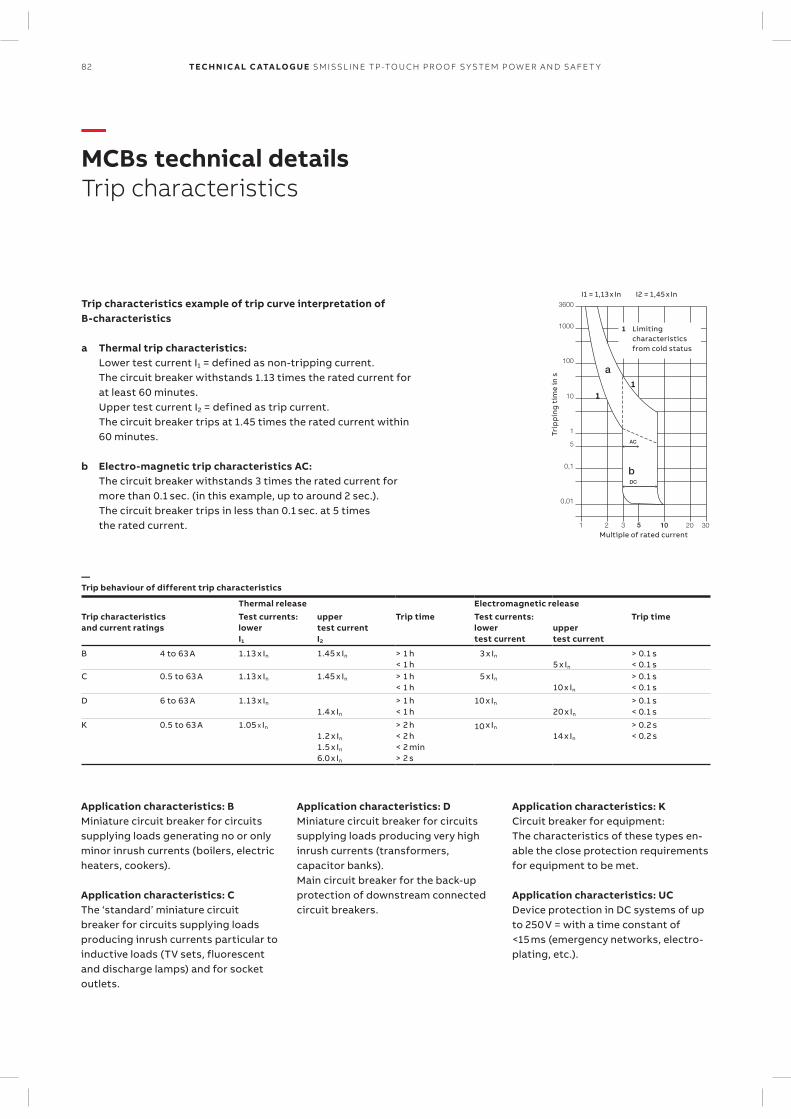
3600
1000
100
10
1
0,1
5
0,01
1 2 3 5 10 20 30
a
bDC
AC
I1 = 1,13 x In I2 = 1,45 x In
11
1 Limiting characteristics from cold status
Trip
pin
g t
ime
in s
Multiple of rated current
82 TECH N I C A L C ATA LO G U E SM ISSL I N E TP -TO U CH PR O O F S Y S TEM P OW ER A N D S A FE T Y
—MCBs technical detailsTrip characteristics
Trip characteristics example of trip curve interpretation of B-characteristics
a Thermal trip characteristics: Lower test current I1 = defined as non-tripping current. The circuit breaker withstands 1.13 times the rated current for
at least 60 minutes. Upper test current I2 = defined as trip current. The circuit breaker trips at 1.45 times the rated current within
60 minutes.
b Electro-magnetic trip characteristics AC: The circuit breaker withstands 3 times the rated current for
more than 0.1 sec. (in this example, up to around 2 sec.). The circuit breaker trips in less than 0.1 sec. at 5 times
the rated current.
—Trip behaviour of different trip characteristics
Thermal release Electromagnetic releaseTrip characteristicsand current ratings
Test currents:lowerI1
uppertest currentI2
Trip time Test currents:lowertest current
uppertest current
Trip time
B 4 to 63 A 1.13 x In 1.45 x In > 1 h< 1 h
3 x In
5 x In
> 0.1 s< 0.1 s
C 0.5 to 63 A 1.13 x In 1.45 x In > 1 h< 1 h
5 x In
10 x In
> 0.1 s< 0.1 s
D 6 to 63 A 1.13 x In
1.4 x In
> 1 h< 1 h
10 x In
20 x In
> 0.1 s< 0.1 s
K 0.5 to 63 A 1.05 X In
1.2 x In
1.5 x In
6.0 x In
> 2 h< 2 h< 2 min> 2 s
10 x In 14 x In
> 0.2 s< 0.2 s
Application characteristics: BMiniature circuit breaker for circuits supplying loads generating no or only minor inrush currents (boilers, electric heaters, cookers).
Application characteristics: CThe ‘standard’ miniature circuit breaker for circuits supplying loads producing inrush currents particular to inductive loads (TV sets, fluorescent and discharge lamps) and for socket outlets.
Application characteristics: DMiniature circuit breaker for circuits supplying loads producing very high inrush currents (transformers, ca pacitor banks).Main circuit breaker for the back-up protection of downstream connected circuit breakers.
Application characteristics: KCircuit breaker for equipment:The characteristics of these types en-able the close protection requirements for equipment to be met.
Application characteristics: UCDevice protection in DC systems of up to 250 V = with a time constant of <15 ms (emergency networks, electro-plating, etc.).
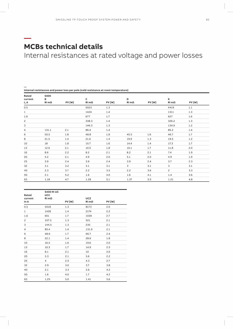
83SM ISSL I N E TP -TO U CH PR O O F S Y S TEM P OW ER A N D S A FE T Y
—MCBs technical detailsInternal resistances at rated voltage and power losses
—Internal resistances and power loss per pole (cold resistance at room temperature)
RatedcurrentIn A
S400 BRi mΩ PV [W]
CRi mΩ
PV [W]DRi mΩ PV [W]
KRi mΩ PV [W]
0.5 5023 1.3 4419 1.1
1 1424 1.4 1311 1.3
1.6 677 1.7 627 1.6
2 338.3 1.4 326.2 1.3
3 146.3 1.3 134.9 1.2
4 131.1 2.1 86.4 1.4 85.2 1.4
6 50.5 1.8 48.8 1.8 45.5 1.6 46.7 1.7
8 21.5 1.4 21.6 1.4 19.9 1.3 19.5 1.2
10 18 1.8 15.7 1.6 14.4 1.4 17.3 1.7
13 12.6 2.1 10.5 1.8 10.1 1.7 11.8 2.0
16 8.6 2.2 8.2 2.1 8.2 2.1 7.4 1.9
20 5.2 2.1 4.9 2.0 5.1 2.0 4.9 1.9
25 3.9 2.4 3.9 2.4 3.9 2.4 3.7 2.3
32 3.1 3.2 3.1 3.1 3 3.1 3 3.1
40 2.3 3.7 2.2 3.5 2.2 3.6 2 3.3
50 2.1 5.2 1.6 4.0 1.6 4.1 1.4 3.6
63 1.18 4.7 1.28 5.1 1.37 5.5 1.21 4.8
RatedcurrentIn A
S400 M-UCUCCRi mΩ
PV [W]UCZRi mΩ
PV [W]
0.5 5018 1.3 8173 2.0
1 1428 1.4 2174 2.2
1.6 651 1.7 1039 2.7
2 337.3 1.3 521 2.1
3 144.5 1.3 235 2.1
4 85.4 1.4 131.9 2.1
6 48.6 1.7 66.7 2.4
8 22.1 1.4 28.6 1.8
10 16.5 1.6 19.6 2.0
13 10.3 1.7 14.9 2.5
16 8.1 2.1 10 2.6
20 5.3 2.1 5.6 2.2
25 4 2.5 4.3 2.7
32 2.9 3.0 3.7 3.8
40 2.1 3.3 2.6 4.2
50 1.6 4.0 1.7 4.2
63 1.25 5.0 1.41 5.6
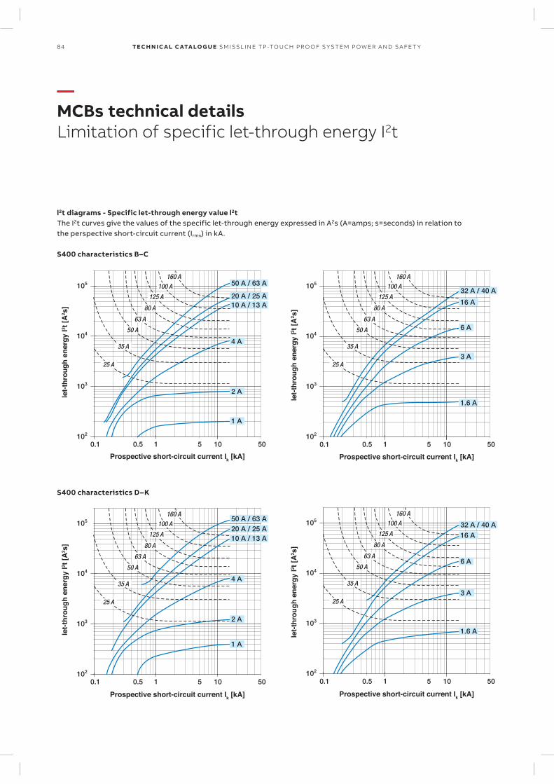
84 TECH N I C A L C ATA LO G U E SM ISSL I N E TP -TO U CH PR O O F S Y S TEM P OW ER A N D S A FE T Y
—MCBs technical detailsLimitation of specific let-through energy I2t
Prospective short-circuit current Ik [kA]
let-
thro
ug
h e
ner
gy
I2 t [
A2 s
]
Prospective short-circuit current Ik [kA]
let-
thro
ug
h e
ner
gy
I2 t [
A2 s
]
Prospective short-circuit current Ik [kA]
let-
thro
ug
h e
ner
gy
I2 t [
A2 s
]
Prospective short-circuit current Ik [kA]
let-
thro
ug
h e
ner
gy
I2 t [
A2 s
]
l2t diagrams - Specific let-through energy value l2tThe I2t curves give the values of the specific let-through energy expressed in A2s (A=amps; s=seconds) in relation to the per spective short-circuit current (Irms) in kA.
S400 characteristics B–C
S400 characteristics D–K
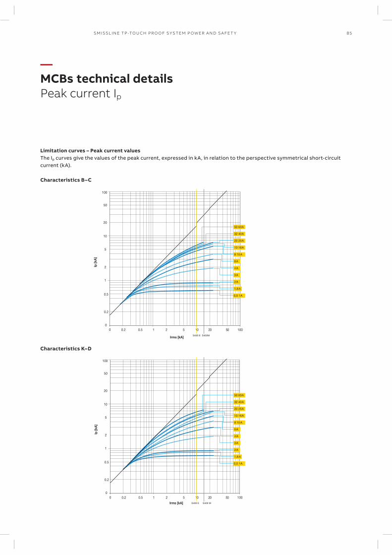
85SM ISSL I N E TP -TO U CH PR O O F S Y S TEM P OW ER A N D S A FE T Y
—MCBs technical detailsPeak current Ip
Ip [k
A]
10
0
20
50
0.2
0.5
100
0
Irms [kA]
0.2 0.5 1 2 5 10 20 50 100
1
2
5
50 63 A
32 40 A
20 25 A
13 16 A
8 10 A
6 A
0,5 1 A
3 A
2 A
1,6 A
4 A
S400 E S400M
Ip [k
A]
10
0
20
50
0.2
0.5
100
0
Irms [kA]
0.2 0.5 1 2 5 10 20 50 100
1
2
5
50 63 A
32 40 A
20 25 A
13 16 A
8 10 A
6 A
0,5 1 A
3 A
2 A
1,6 A
4 A
S400 E S400 M
Limitation curves – Peak current valuesThe Ip curves give the values of the peak current, expressed in kA, in relation to the perspective symmetrical short-circuit current (kA).
Characteristics B–C
Characteristics K–D
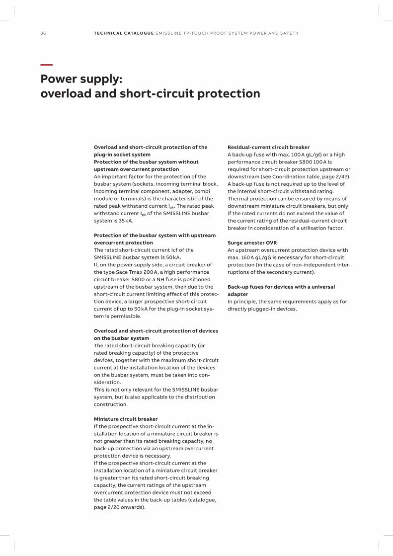
86 TECH N I C A L C ATA LO G U E SM ISSL I N E TP -TO U CH PR O O F S Y S TEM P OW ER A N D S A FE T Y
—Power supply: overload and short-circuit protection
Overload and short-circuit protection of the plug-in socket systemProtection of the busbar system without upstream overcurrent protectionAn important factor for the protection of the busbar system (sockets, incoming terminal block, incoming terminal component, adapter, combi module or terminals) is the characteristic of the rated peak withstand current Ipk. The rated peak withstand current Ipk of the SMISSLINE busbar system is 35 kA.
Protection of the busbar system with upstream overcurrent protectionThe rated short-circuit current Icf of the SMISSLINE busbar system is 50 kA.If, on the power supply side, a circuit breaker of the type Sace Tmax 200 A, a high performance circuit breaker S800 or a NH fuse is positioned upstream of the busbar system, then due to the short-circuit current limiting effect of this protec-tion device, a larger prospective short-circuit current of up to 50 kA for the plug-in socket sys-tem is permissible.
Overload and short-circuit protection of devices on the busbar systemThe rated short-circuit breaking capacity (or rated breaking capacity) of the protective devices, together with the maximum short-circuit current at the installation location of the devices on the busbar system, must be taken into con-sideration.This is not only relevant for the SMISSLINE busbar system, but is also applicable to the distribution construction.
Miniature circuit breakerIf the prospective short-circuit current at the in-stallation location of a miniature circuit breaker is not greater than its rated breaking capacity, no back-up protection via an upstream over current protection device is necessary.If the prospective short-circuit current at the installation location of a miniature circuit breaker is greater than its rated short-circuit breaking capacity, the current ratings of the upstream overcurrent protection device must not exceed the table values in the back-up tables (catalogue, page 2/20 onwards).
Residual-current circuit breakerA back-up fuse with max. 100 A gL/gG or a high performance circuit breaker S800 100 A is required for short-circuit protection upstream or downstream (see Coordination table, page 2/42). A back-up fuse is not required up to the level of the internal short-circuit withstand rating. Thermal protection can be ensured by means of downstream miniature circuit breakers, but only if the rated currents do not exceed the value of the current rating of the residual- current circuit breaker in consideration of a utilisation factor.
Surge arrester OVRAn upstream overcurrent protection device with max. 160 A gL/gG is necessary for short- circuit protection (in the case of non-independent inter-ruptions of the secondary current).
Back-up fuses for devices with a universal adapterIn principle, the same requirements apply as for directly plugged-in devices.
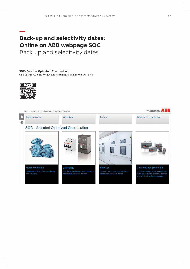
87SM ISSL I N E TP -TO U CH PR O O F S Y S TEM P OW ER A N D S A FE T Y
—Back-up and selectivity dates: Online on ABB webpage SOCBack-up and selectivity dates
SOC - Selected Optimized CoordinationSee as well ABB on http://applications.it.abb.com/SOC_SNB
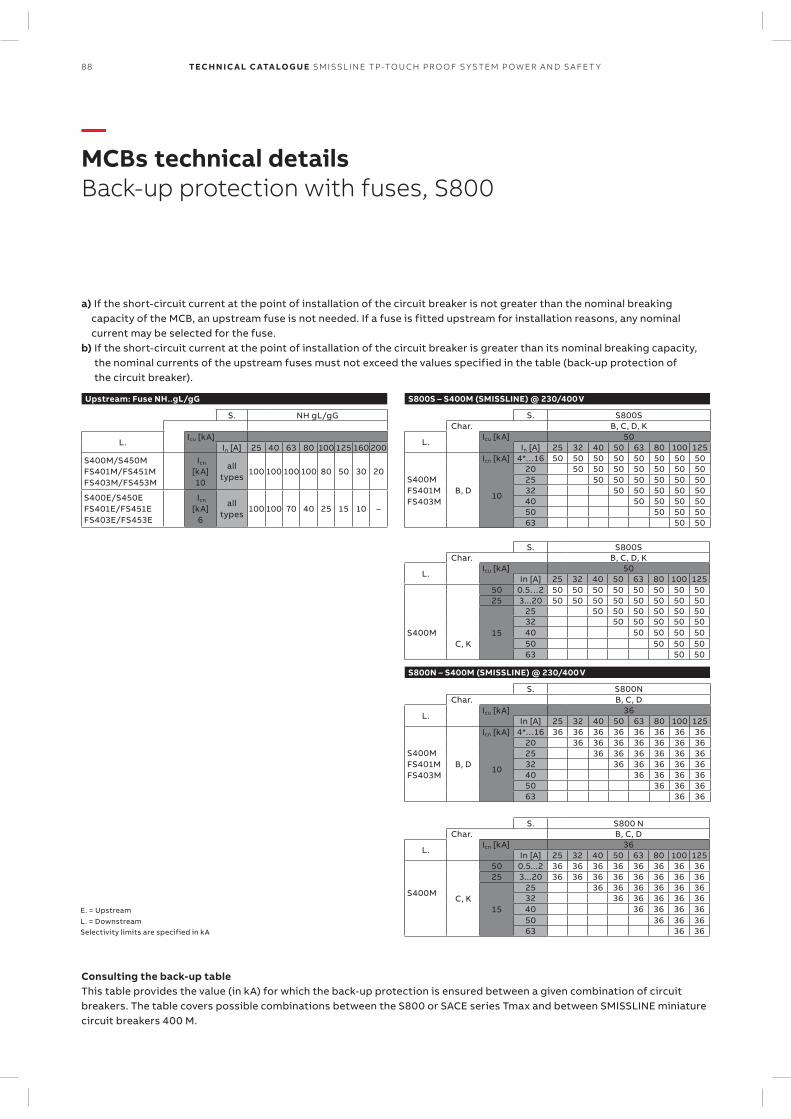
88 TECH N I C A L C ATA LO G U E SM ISSL I N E TP -TO U CH PR O O F S Y S TEM P OW ER A N D S A FE T Y
—MCBs technical detailsBack-up protection with fuses, S800
a) If the short-circuit current at the point of installation of the circuit breaker is not greater than the nominal breaking capacity of the MCB, an upstream fuse is not needed. If a fuse is fitted upstream for installation reasons, any nominal current may be selected for the fuse.
b) If the short-circuit current at the point of installation of the circuit breaker is greater than its nominal breaking capacity, the nominal currents of the upstream fuses must not exceed the values specified in the table (back-up protection of the circuit breaker).
Consulting the back-up tableThis table provides the value (in kA) for which the back-up protection is ensured between a given combination of circuit breakers. The table covers possible combinations between the S800 or SACE series Tmax and between SMISSLINE miniature circuit breakers 400 M.
E. = UpstreamL. = DownstreamSelectivity limits are specified in kA
S. S800S Char. B, C, D, K
L. Icu [kA] 50
In [A] 25 32 40 50 63 80 100 12550 0.5…2 50 50 50 50 50 50 50 5025 3...20 50 50 50 50 50 50 50 50
S400MC, K
15
25 50 50 50 50 50 5032 50 50 50 50 5040 50 50 50 5050 50 50 5063 50 50
S800S – S400M (SMISSLINE) @ 230/400 V
S. S800S Char. B, C, D, K
L. Icu [kA] 50
In [A] 25 32 40 50 63 80 100 125
S400MFS401MFS403M
B, D
Icn [kA] 4*…16 50 50 50 50 50 50 50 50
10
20 50 50 50 50 50 50 5025 50 50 50 50 50 5032 50 50 50 50 5040 50 50 50 5050 50 50 5063 50 50
S800N – S400M (SMISSLINE) @ 230/400 V
S. S800N Char. B, C, D
L. Icu [kA] 36
In [A] 25 32 40 50 63 80 100 125
S400MFS401MFS403M
B, D
Icn [kA] 4*…16 36 36 36 36 36 36 36 36
10
20 36 36 36 36 36 36 3625 36 36 36 36 36 3632 36 36 36 36 3640 36 36 36 3650 36 36 3663 36 36
S. S800 N Char. B, C, D
L. Icn [kA] 36
In [A] 25 32 40 50 63 80 100 125
S400MC, K
50 0.5...2 36 36 36 36 36 36 36 3625 3...20 36 36 36 36 36 36 36 36
15
25 36 36 36 36 36 3632 36 36 36 36 3640 36 36 36 3650 36 36 3663 36 36
Upstream: Fuse NH..gL/gG
S. NH gL/gG
L. Icu [kA]
In [A] 25 40 63 80 100 125 160 200S400M/S450MFS401M/FS451MFS403M/FS453M
Icn [kA]10
alltypes
100 100 100 100 80 50 30 20
S400E/S450EFS401E/FS451EFS403E/FS453E
Icn [kA]6
alltypes
100 100 70 40 25 15 10 –
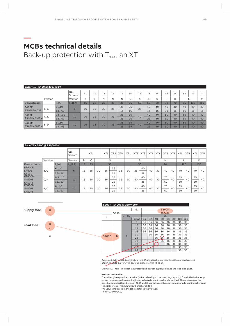
89SM ISSL I N E TP -TO U CH PR O O F S Y S TEM P OW ER A N D S A FE T Y
—MCBs technical detailsBack-up protection with Tmax an XT
Sace Tmax – S400 @ 230/400 V
Up- Stream
T1 T1 T1 T2 T3 T4 T2 T3 T4 T2 T4 T2 T4 T4
Version Version B C N N N N S S S H H L V
Downstream ln [A] lcu [kA] 16 25 36 36 36 36 50 50 50 70 70 85 120 200
S400E FS401E/403E
B, C6…10
6 16 25 30 3636 36
3640 40 40 30 40 40 40
13…63 16 16 16 16 16 16 16 16 16
S400M FS401M/403M
C, K0.5…10
10 16 25 30 3636 36
4040 40 50 40 50 40 40
13…63 25 36 25 40 50 40 50 40 40
S400M FS401M/403M
B, D6…10
10 16 25 30 3636 36
4040 40 50 40 50 40 40
13…63 25 36 25 40 50 40 50 40 40
Sace XT – S400 @ 230/400 V
Up- Stream
XT1 XT2 XT3 XT4 XT1 XT2 XT3 XT4 XT1 XT2 XT4 XT2 XT4 XT2 XT4
Version Version B C N S H L V
Downstream ln [A] lcu [kA] 18 25 36 50 70 120 150FS400ES400E S450E
B, C6…10
6 18 25 30 3636
36 30 3640
40 30 40 40 40 40 40 4013…63 16 16
FS400MS400M S450M
C, K0.5…10
10 18 25 30 3636
36 30 5040
40 3070
4085
4085
4013…63 25 25 60 60 60
FS400MS400M S450M
B, D6…10
10 18 25 30 3636
36 30 5040
40 3070
4085
4085
4013…63 25 25 60 60 60
Supply side
Load side
S800N - S400E @ 230/400 V
E. S800N Char. B, C, D
L. Icu [kA] 36
In [A] 25 32 40 50 63 80 100 125
S400E B 6
6 36 36 36 36 36 36 36 3610 36 36 36 36 36 36 36 3613 36 36 36 36 36 36 36 3616 36 36 36 36 36 36 36 3620 36 36 36 36 36 36 3625 36 36 36 36 36 3632 36 36 36 36 3640 36 36 36 3636 36 36 3663 36 36
Example 1: With a S800 nominal current 50 A is a Back-up protection till a nominal current of 25 A to a S400 given. The Back-up protection ist till 36 kA. Example 2: There is no Back-up protection between supply side and the load side given.
Back-up protection The tables given provide the value (in kA, referring to the breaking capacity) for which the back-up protection among the combination of selected circuit breakers is verified. The tables cover the possible combinations between S800 and those between the above mentioned circuit breakers and the ABB series of modular circuit breakers S400. The values indicated in the tables refer to the voltage: – Vn of 230/400VAC
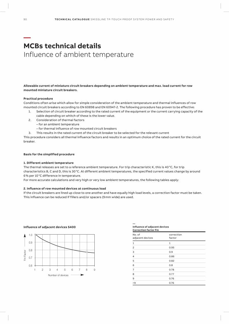
90 TECH N I C A L C ATA LO G U E SM ISSL I N E TP -TO U CH PR O O F S Y S TEM P OW ER A N D S A FE T Y
—MCBs technical detailsInfluence of ambient temperature
Allowable current of miniature circuit breakers depending on ambient temperature and max. load current for row mounted miniature circuit breakers.
Practical procedure Conditions often arise which allow for simple consideration of the ambient temperature and thermal influences of row mounted circuit breakers according to EN 60898 and EN 60947-2. The following procedure has proven to be effective:
1. Selection of circuit breaker according to the rated current of the equipment or the current carrying capacity of the cable depending on whitch of these is the lower value.
2. Consideration of thermal factors – for an ambient temperature – for thermal influence of row mounted circuit breakers
3. This results in the rated current of the circuit breaker to be selected for the relevant currentThis procedure considers all thermal influence factors and results in an optimum choice of the rated current for the circuit breaker.
Basis for the simplified procedure
1. Different ambient temperatureThe thermal releases are set to a reference ambient temperature. For trip characteristic K, this is 40 °C, for trip characteristics B, C and D, this is 30 °C. At different ambient temperatures, the specified current values change by around 6 % per 10 °C difference in temperature. For more accurate calculations and very high or very low ambient temperatures, the following tables apply:
2. Influence of row mounted devices at continuous loadIf the circuit breakers are lined up close to one another and have equally high load levels, a correction factor must be taken. This influence can be reduced if fillers and/or spacers (9 mm wide) are used.
Influence of adjacent devices S400—Influence of adjacent devicesCorrection factor Fm
No. ofadjacent devices
correctionfactor
1 1
2 0.95
3 0.9
4 0.86
5 0.82
6 0.8
7 0.78
8 0.77
9 0.76
>9 0.76
1 2 3 4 5 6 7 8 90.6
0.7
0.8
0.9
1.0
Fm F
acto
r
Number of devices
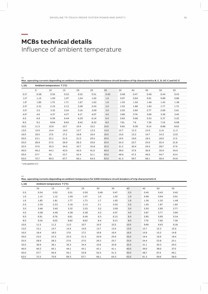
91SM ISSL I N E TP -TO U CH PR O O F S Y S TEM P OW ER A N D S A FE T Y
—MCBs technical detailsInfluence of ambient temperature
—Max. operating currents depending on ambient temperature for S400 miniature circuit breakers of tip characteristics B, C, D, UC-C and UC-Z
In (A) Ambient temperature T (°C)
0 10 15 20 25 30 35 40 45 50 55
0.5* 0.58 0.55 0.53 0.52 0.51 0.50 0.48 0.47 0.46 0.44 0.43
1.0* 1.15 1.09 1.07 1.04 1.02 1.0 0.97 0.94 0.91 0.89 0.86
1.6* 1.85 1.75 1.71 1.67 1.63 1.6 1.55 1.50 1.46 1.42 1.38
2.0* 2.31 2.19 2.13 2.08 2.03 2.0 1.93 1.88 1.83 1.77 1.72
3.0* 3.5 3.32 3.24 3.16 3.09 3.0 2.93 2.85 2.77 2.69 2.61
4.0* 4.6 4.37 4.27 4.17 4.07 4.0 3.86 3.76 3.66 3.56 3.45
6.0 6.9 6.59 6.44 6.29 6.14 6.0 5.83 5.68 5.53 5.37 5.22
8.0 9.2 8.84 8.63 8.42 8.22 8.0 7.81 7.6 7.39 7.19 6.98
10.0 11.5 10.9 10.7 10.4 10.2 10.0 9.65 9.39 9.14 8.88 8.63
13.0 15.0 14.4 14.0 13.7 13.3 13.0 12.7 12.3 12.0 11.6 11.3
16.0 18.5 17.6 17.2 16.8 16.4 16.0 15.6 15.2 14.7 14.3 13.9
20.0 23.1 22.1 21.6 21.0 20.5 20.0 19.5 19.0 18.5 18.0 17.5
25.0 28.9 27.5 26.9 26.3 25.6 25.0 24.3 23.7 23.0 22.4 21.8
32.0 37.0 35.3 34.5 33.7 32.8 32.0 31.2 30.4 29.5 28.7 27.9
40.0 46.2 44.1 43.0 42.0 41.0 40.0 39.0 37.9 36.9 35.9 34.9
50.0 57.7 55 53.7 52.4 51.1 50.0 48.6 47.3 46.0 44.7 43.4
63.0 72.7 69.3 67.7 66.1 64.5 63.0 61.3 59.7 58.1 56.4 54.8
* only applies to C
—Max. operating currents depending on ambient temperature for S400 miniature circuit breakers of trip characteristic K
In (A) Ambient temperature T (°C)
10 15 20 25 30 35 40 45 50 55
0.5 0.54 0.52 0.51 0.50 0.49 0.47 0.5 0.45 0.43 0.42
1.0 1.14 1.12 1.09 1.07 1.0 1.02 1.0 0.96 0.94 0.91
1.6 1.85 1.81 1.77 1.73 1.7 1.65 1.6 1.56 1.52 1.48
2.0 2.29 2.23 2.18 2.13 2.1 2.03 2.0 1.93 1.87 1.82
3.0 3.48 3.40 3.32 3.25 3.2 3.09 3.0 2.93 2.85 2.77
4.0 4.58 4.48 4.38 4.28 4.2 4.07 4.0 3.87 3.77 3.66
6.0 6.91 6.76 6.61 6.46 6.3 6.15 6.0 5.85 5.69 5.54
8.0 9.24 9.03 8.82 8.62 8.4 8.21 8.0 7.79 7.59 7.38
10.0 11.5 11.2 11.0 10.7 10.5 10.2 10.0 9.69 9.43 9.18
13.0 15.1 14.7 14.4 14.0 13.7 13.4 13.0 12.7 12.3 12.0
16.0 18.4 18.0 17.6 17.2 16.8 16.4 16.0 15.6 15.2 14.8
20.0 23.0 22.5 22.0 21.5 20.9 20.4 20.0 19.4 18.9 18.4
25.0 28.9 28.3 27.6 27.0 26.3 25.7 25.0 24.4 23.8 23.1
32.0 36.9 36.1 35.3 34.4 33.6 32.8 32.0 31.1 30.3 29.5
40.0 46.2 45.1 44.1 43.1 42.1 41.1 40.0 39.0 38.0 37.0
50.0 57.7 56.4 55.1 53.8 52.5 51.3 50.0 48.7 47.4 46.1
63.0 72.5 70.9 69.3 67.7 66.1 64.5 63.0 61.3 59.6 58.0
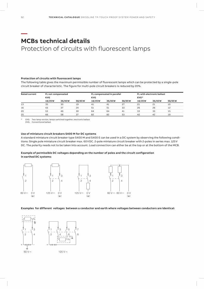
92 TECH N I C A L C ATA LO G U E SM ISSL I N E TP -TO U CH PR O O F S Y S TEM P OW ER A N D S A FE T Y
—MCBs technical detailsProtection of circuits with fluorescent lamps
x1
2
60 V()0 V
x1
2
x3
4
125 V()0 V
x1
2
x3
4
125 V()0 V
()0 V
x1
2
x3
4
60 V 60 V
x1
2
x3
4
60 V
+ –
x1 5
2
x3
4
x
6
x7
8
125 V
+
Protection of circuits with fluorescent lampsThe following table gives the maximum permissible number of fluorescent lamps which can be protected by a single-pole circuit breaker of characteristic. The figure for multi-pole circuit breakers is reduced by 20%.
Rated current FL not compensated FL compensated in parallel FL with electronic ballastKVG KVG EVG1)
18/20 W 36/40 W 58/65 W 18/20 W 36/40 W 58/65 W 18/20 W 36/40 W 58/65 W13 35 30 19 41 41 27 21 21 1016 43 37 24 51 51 33 26 26 1220 53 46 30 64 64 41 33 33 1525 66 58 37 82 82 53 42 42 19
1) EVG: Two-lamp version, lamps switched together, electronic ballast KVG: Conventional ballast
Use of miniature circuit breakers S400 M for DC systemsA standard miniature circuit breaker type S400 M and S400 E can be used in a DC system by observing the following condi-tions: Single pole miniature circuit breaker max. 60 V DC. 2-pole miniature circuit breaker with 2-poles in series max. 125 V DC. The polarity needs not to be taken into account. Load connection can either be at the top or at the bottom of the MCB.
Example of permissible DC voltages depending on the number of poles and the circuit configeration in earthed DC systems:
Examples for different voltages between a conductor and earth where voltages between conductors are identical:
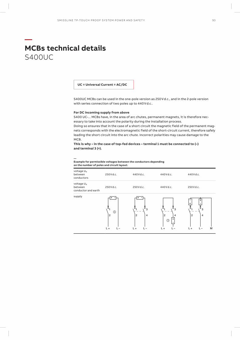
93SM ISSL I N E TP -TO U CH PR O O F S Y S TEM P OW ER A N D S A FE T Y
—MCBs technical detailsS400UC
S400UC MCBs can be used in the one-pole version as 250 V d.c., and in the 2-pole version with series connection of two poles up to 440 V d.c..
For DC incoming supply from aboveS400 UC-... MCBs have, in the area of arc chutes, permanent magnets, it is therefore nec-essary to take into account the polarity during the installation process. Doing so ensures that in the case of a short circuit the magnetic field of the permanent mag-nets corresponds with the electromagnetic field of the short-circuit current, therefore safely leading the short circuit into the arc chute. Incorrect polarities may cause damage to the MCB.This is why – in the case of top-fed devices – terminal 1 must be connected to (–) and terminal 3 (+).
—Example for permissible voltages between the conductors depending on the number of poles and circuit layout:
voltage UN
betweenconductors
250 V d.c. 440 V d.c. 440 V d.c. 440 V d.c.
voltage UN
betweenconductor and earth
250 V d.c. 250 V d.c. 440 V d.c. 250 V d.c.
supply
11
L + L –
2
L + L –
1
2
3
4
1
L + L –
1
2
3
4
L + L – M
1
2
3
4
UC = Universal Current = AC/DC
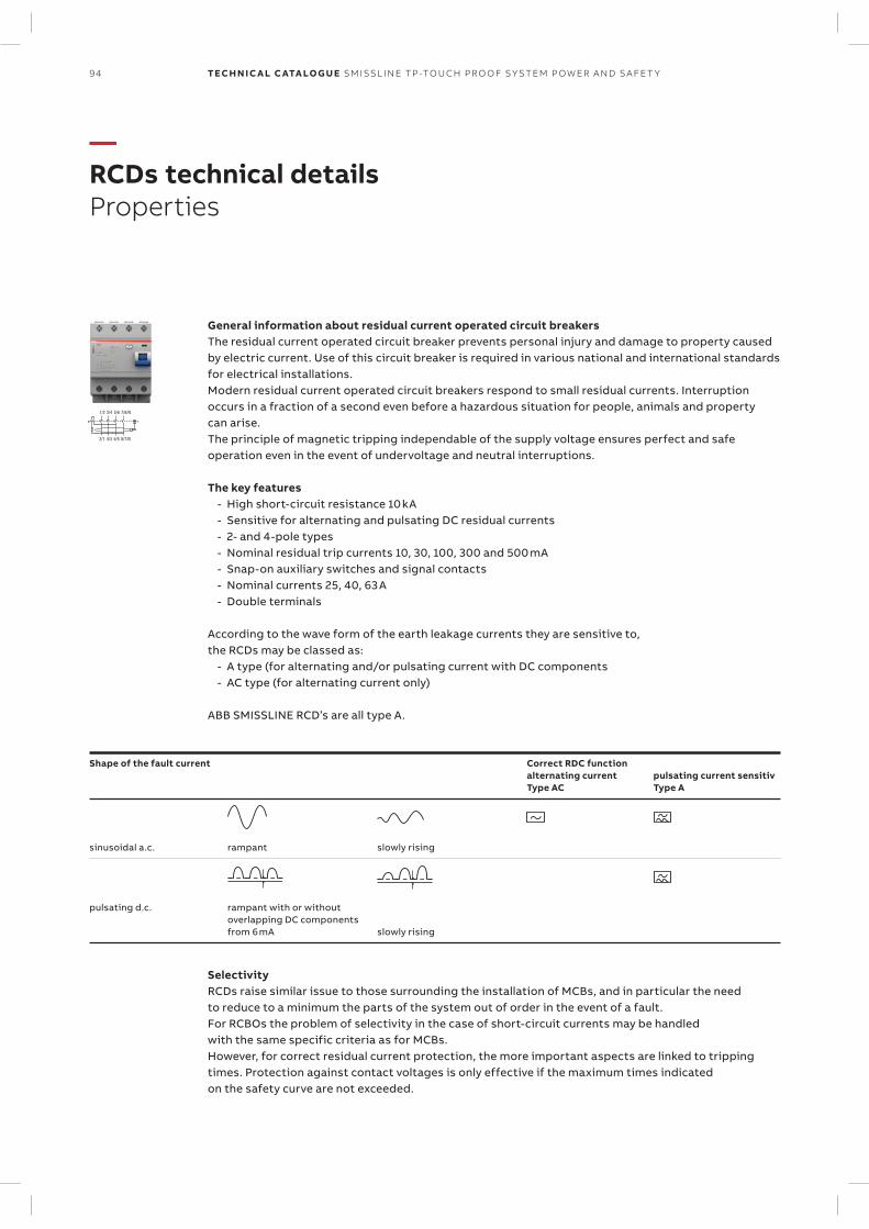
94 TECH N I C A L C ATA LO G U E SM ISSL I N E TP -TO U CH PR O O F S Y S TEM P OW ER A N D S A FE T Y
—RCDs technical detailsProperties
1/2 3/4
2/1 4/3
5/6 7/8/N
6/5 8/7/N
General information about residual current operated circuit breakersThe residual current operated circuit breaker prevents personal injury and damage to property caused by electric current. Use of this circuit breaker is required in various national and international standards for electrical installations. Modern residual current operated circuit breakers respond to small residual currents. Interruption occurs in a fraction of a second even before a hazardous situation for people, animals and property can arise. The principle of magnetic tripping independable of the supply voltage ensures perfect and safe operation even in the event of undervoltage and neutral interruptions.
The key features - High short-circuit resistance 10 kA - Sensitive for alternating and pulsating DC residual currents - 2- and 4-pole types - Nominal residual trip currents 10, 30, 100, 300 and 500 mA - Snap-on auxiliary switches and signal contacts - Nominal currents 25, 40, 63 A - Double terminals
According to the wave form of the earth leakage currents they are sensitive to, the RCDs may be classed as:
- A type (for alternating and/or pulsating current with DC components - AC type (for alternating current only)
ABB SMISSLINE RCD’s are all type A.
Shape of the fault current Correct RDC functionalternating currentType AC
pulsating current sensitivType A
sinusoidal a.c. rampant slowly rising
pulsating d.c. rampant with or withoutoverlapping DC componentsfrom 6 mA slowly rising
SelectivityRCDs raise similar issue to those surrounding the installation of MCBs, and in particular the need to reduce to a minimum the parts of the system out of order in the event of a fault. For RCBOs the problem of selectivity in the case of short-circuit currents may be handled with the same specific criteria as for MCBs. However, for correct residual current protection, the more important aspects are linked to tripping times. Protection against contact voltages is only effective if the maximum times indicated on the safety curve are not exceeded.
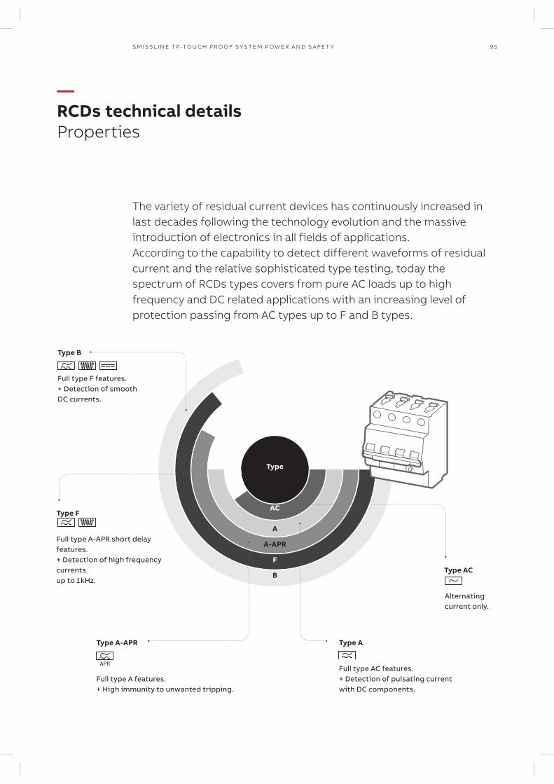
95SM ISSL I N E TP -TO U CH PR O O F S Y S TEM P OW ER A N D S A FE T Y
—RCDs technical detailsProperties
The variety of residual current devices has continuously increased in last decades following the technology evolution and the massive introduction of electronics in all fields of applications.According to the capability to detect different waveforms of residual current and the relative sophisticated type testing, today the spectrum of RCDs types covers from pure AC loads up to high frequency and DC related applications with an increasing level of protection passing from AC types up to F and B types.
Full type A-APR short delay features. + Detection of high frequency currents up to 1 kHz.
Type F
Type B
Full type F features. + Detection of smooth DC currents.
Full type A features. + High immunity to unwanted tripping.
Type A-APR
Alternating current only.
Type AC
Full type AC features. + Detection of pulsating current with DC components.
Type A
Type
A
AC
A-APR
F
B
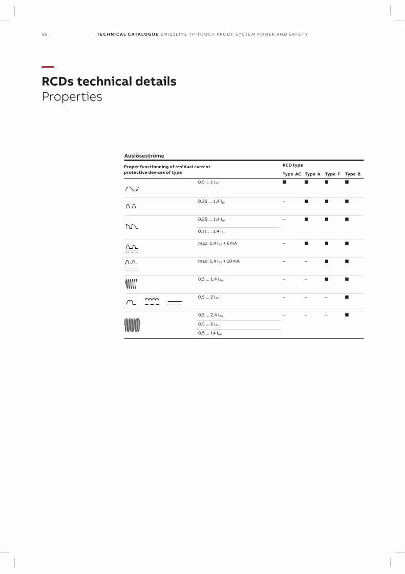
96 TECH N I C A L C ATA LO G U E SM ISSL I N E TP -TO U CH PR O O F S Y S TEM P OW ER A N D S A FE T Y
—RCDs technical detailsProperties
Auslöseströme
Proper functionning of residual current protective devices of type
RCD type
Type AC Type A Type F Type B
0,5 ... 1 IΔn
0,35 ... 1,4 IΔn –
0,25 ... 1,4 IΔn –
0,11 ... 1,4 IΔn
max. 1,4 IΔn + 6 mA –
max. 1,4 IΔn + 10 mA – –
0,5 ... 1,4 IΔn – –
0,5 ... 2 IΔn – – –
0,5 ... 2,4 IΔn – – –
0,5 ... 6 IΔn
0,5 ... 14 IΔn
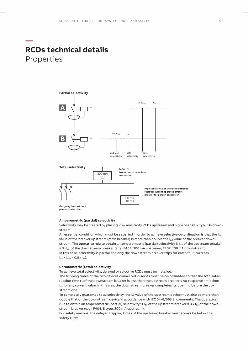
97SM ISSL I N E TP -TO U CH PR O O F S Y S TEM P OW ER A N D S A FE T Y
—RCDs technical detailsProperties
0.5 x I∆1 I∆1
0.5 x I∆2 I∆2
dubiousselectivity
safeselectivity
safeselectivity
I∆1
I∆2
A
B
300 mAs
30 mA10 mA
High sensitivity or short time delayed residual current operated circuit breaker for person protection
F400…SProtection of complete installation
Outgoing lines without person protection
Partial selectivity
Total selectivity
Amperometric (partial) selectivitySelectivity may be created by placing low-sensitivity RCDs upstream and higher-sensitivity RCDs down-stream. An essential condition which must be satisfied in order to achieve selective co-ordination is that the I∆1
value of the breaker upstream (main breaker) is more than double the IΔ2 value of the breaker down-stream. The operative rule to obtain an amperometric (partial) selectivity is IΔn of the upstream breaker = 3 x IΔn of the downstream breaker (e. g.: F404, 300 mA upstream; F402, 100 mA downstream). In this case, selectivity is partial and only the downstream breaker trips for earth fault currents IΔ2 < IΔm < 0,5 x IΔ1).
Chronometric (total) selectivityTo achieve total selectivity, delayed or selective RCDs must be installed. The tripping times of the two devices connected in series must be co-ordinated so that the total inter-ruption time t2 of the downstream breaker is less than the upstream breaker’s no-response limit time t1, for any current value. In this way, the downstream breaker completes its opening before the up-stream one. To completely guarantee total selectivity, the IΔ value of the upstream device must also be more than double that of the downstream device in accordance with IEC 64-8/563.3, comments. The operative rule to obtain an amperometric (partial) selectivity is IΔn of the upstream breaker = 3 x IΔn of the down-stream breaker (e. g.: F404, S type, 300 mA upstream). For safety reasons, the delayed tripping times of the upstream breaker must always be below the safety curve.
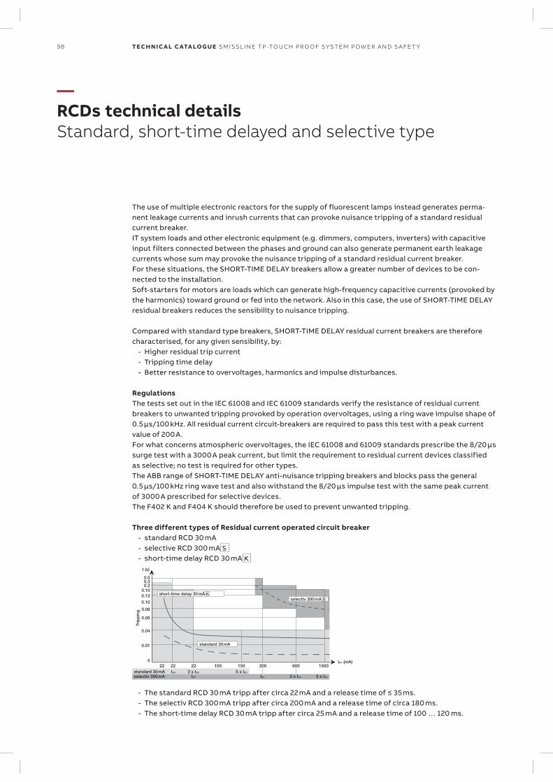
short-time delay 30mA Kselectiv 300mA S
standard 30mA
standard 30mA
t (s)
0.50.30.2
0.150.130.10
0.06
0.05
0.04
0.01
022 22 22 100 150 300 600 1500
IΔn (mA)
5 x IΔn2 x IΔnIΔnIΔn
IΔn 2 x IΔn 5 x IΔn
Trip
pin
g
selectiv 300mA
98 TECH N I C A L C ATA LO G U E SM ISSL I N E TP -TO U CH PR O O F S Y S TEM P OW ER A N D S A FE T Y
—RCDs technical detailsStandard, short-time delayed and selective type
The use of multiple electronic reactors for the supply of fluorescent lamps instead generates perma-nent leakage currents and inrush currents that can provoke nuisance tripping of a standard residual current breaker. IT system loads and other electronic equipment (e.g. dimmers, computers, inverters) with capacitive input filters connected between the phases and ground can also generate permanent earth leakage currents whose sum may provoke the nuisance tripping of a standard residual current breaker. For these situations, the SHORT-TIME DELAY breakers allow a greater number of devices to be con-nected to the installation. Soft-starters for motors are loads which can generate high-frequency capacitive currents (provoked by the harmonics) toward ground or fed into the network. Also in this case, the use of SHORT-TIME DELAY residual breakers reduces the sensibility to nuisance tripping.
Compared with standard type breakers, SHORT-TIME DELAY residual current breakers are therefore characterised, for any given sensibility, by:
- Higher residual trip current - Tripping time delay - Better resistance to overvoltages, harmonics and impulse disturbances.
RegulationsThe tests set out in the IEC 61008 and IEC 61009 standards verify the resistance of residual current breakers to unwanted tripping provoked by operation overvoltages, using a ring wave impulse shape of 0.5 μs/100 kHz. All residual current circuit-breakers are required to pass this test with a peak current value of 200 A. For what concerns atmospheric overvoltages, the IEC 61008 and 61009 standards prescribe the 8/20 μs surge test with a 3000 A peak current, but limit the requirement to residual current devices classified as selective; no test is required for other types.The ABB range of SHORT-TIME DELAY anti-nuisance tripping breakers and blocks pass the general 0.5 μs/100 kHz ring wave test and also withstand the 8/20 μs impulse test with the same peak current of 3000 A prescribed for selective devices. The F402 K and F404 K should therefore be used to prevent unwanted tripping.
Three different types of Residual current operated circuit breaker - standard RCD 30 mA - selective RCD 300 mA S - short-time delay RCD 30 mA K
- The standard RCD 30 mA tripp after circa 22 mA and a release time of ≤ 35 ms. - The selectiv RCD 300 mA tripp after circa 200 mA and a release time of circa 180 ms. - The short-time delay RCD 30 mA tripp after circa 25 mA and a release time of 100 … 120 ms.
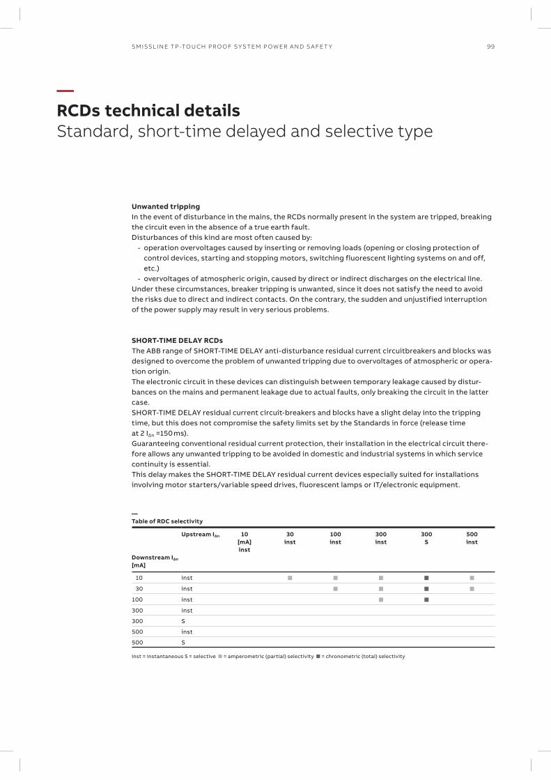
99SM ISSL I N E TP -TO U CH PR O O F S Y S TEM P OW ER A N D S A FE T Y
—RCDs technical detailsStandard, short-time delayed and selective type
Unwanted trippingIn the event of disturbance in the mains, the RCDs normally present in the system are tripped, breaking the circuit even in the absence of a true earth fault.Disturbances of this kind are most often caused by:
- operation overvoltages caused by inserting or removing loads (opening or closing protection of control devices, starting and stopping motors, switching fluorescent lighting systems on and off, etc.)
- overvoltages of atmospheric origin, caused by direct or indirect discharges on the electrical line.Under these circumstances, breaker tripping is unwanted, since it does not satisfy the need to avoid the risks due to direct and indirect contacts. On the contrary, the sudden and unjustified interruption of the power supply may result in very serious problems.
SHORT-TIME DELAY RCDsThe ABB range of SHORT-TIME DELAY anti-disturbance residual current circuitbreakers and blocks was designed to overcome the problem of unwanted tripping due to overvoltages of atmospheric or opera-tion origin. The electronic circuit in these devices can distinguish between temporary leakage caused by distur-bances on the mains and permanent leakage due to actual faults, only breaking the circuit in the latter case. SHORT-TIME DELAY residual current circuit-breakers and blocks have a slight delay into the tripping time, but this does not compromise the safety limits set by the Standards in force (release time at 2 I∆n =150 ms). Guaranteeing conventional residual current protection, their installation in the electrical circuit there-fore allows any unwanted tripping to be avoided in domestic and industrial systems in which service continuity is essential. This delay makes the SHORT-TIME DELAY residual current devices especially suited for installations involving motor starters/variable speed drives, fluorescent lamps or IT/electronic equipment.
—Table of RDC selectivity
Downstream I∆n
[mA]
Upstream I∆n 10[mA]inst
30inst
100inst
300inst
300S
500inst
10 inst
30 inst
100 inst
300 inst
300 S
500 inst
500 S
inst = instantaneous S = selective = amperometric (partial) selectivity = chronometric (total) selectivity
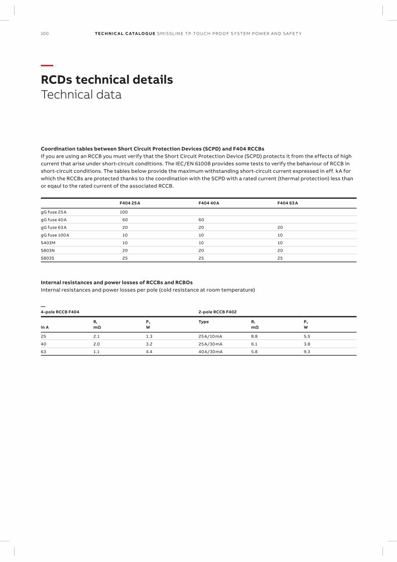
100 TECH N I C A L C ATA LO G U E SM ISSL I N E TP -TO U CH PR O O F S Y S TEM P OW ER A N D S A FE T Y
—RCDs technical detailsTechnical data
Coordination tables between Short Circuit Protection Devices (SCPD) and F404 RCCBsIf you are using an RCCB you must verify that the Short Circuit Protection Device (SCPD) protects it from the effects of high current that arise under short-circuit conditions. The IEC/EN 61008 provides some tests to verify the behaviour of RCCB in short-circuit conditions. The tables below provide the maximum withstanding short-circuit current expressed in eff. kA for which the RCCBs are protected thanks to the coordination with the SCPD with a rated current (thermal protection) less than or eqaul to the rated current of the associated RCCB.
F404 25 A F404 40 A F404 63 A
gG fuse 25 A 100
gG fuse 40 A 60 60
gG fuse 63 A 20 20 20
gG fuse 100 A 10 10 10
S403M 10 10 10
S803N 20 20 20
S803S 25 25 25
Internal resistances and power losses of RCCBs and RCBOsInternal resistances and power losses per pole (cold resistance at room temperature)
—4-pole RCCB F404 2-pole RCCB F402
in ARi
mΩPv
WType Ri
mΩPv
W
25 2.1 1.3 25 A/10 mA 8.8 5.5
40 2.0 3.2 25 A/30 mA 6.1 3.8
63 1.1 4.4 40 A/30 mA 5.8 9.3
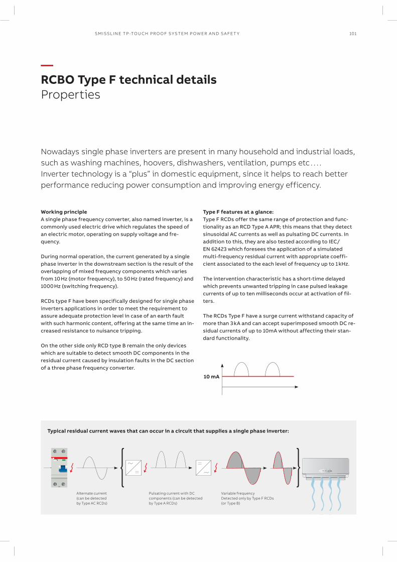
101SM ISSL I N E TP -TO U CH PR O O F S Y S TEM P OW ER A N D S A FE T Y
—RCBO Type F technical detailsProperties
Type F features at a glance:Type F RCDs offer the same range of protection and func-tionality as an RCD Type A APR; this means that they detect sinusoidal AC currents as well as pulsating DC currents. In addition to this, they are also tested according to IEC/EN 62423 which foresees the application of a simulated multi-frequency residual current with appropriate coeffi-cient associated to the each level of frequency up to 1 kHz.
The intervention characteristic has a short-time delayed which prevents unwanted tripping in case pulsed leakage currents of up to ten milliseconds occur at activation of fil-ters. The RCDs Type F have a surge current withstand capacity of more than 3 kA and can accept superimposed smooth DC re-sidual currents of up to 10mA without affecting their stan-dard functionality.
Nowadays single phase inverters are present in many household and industrial loads, such as washing machines, hoovers, dishwashers, ventilation, pumps etc . . . . Inverter technology is a “plus” in domestic equipment, since it helps to reach better performance reducing power consumption and improving energy efficency.
10 mA
Working principleA single phase frequency converter, also named inverter, is a commonly used electric drive which regulates the speed of an electric motor, operating on supply voltage and fre-quency. During normal operation, the current generated by a single phase inverter in the downstream section is the result of the overlapping of mixed frequency components which varies from 10 Hz (motor frequency), to 50 Hz (rated frequency) and 1000 Hz (switching frequency).
RCDs type F have been specifically designed for single phase inverters applications in order to meet the requirement to assure adequate protection level in case of an earth fault with such harmonic content, offering at the same time an in-creased resistance to nuisance tripping. On the other side only RCD type B remain the only devices which are suitable to detect smooth DC components in the residual current caused by insulation faults in the DC section of a three phase frequency converter.
Typical residual current waves that can occur in a circuit that supplies a single phase inverter:
Variable frequency Detected only by Type F RCDs (or Type B)
Alternate current (can be detected by Type AC RCDs)
Pulsating current with DC components (can be detected by Type A RCDs)
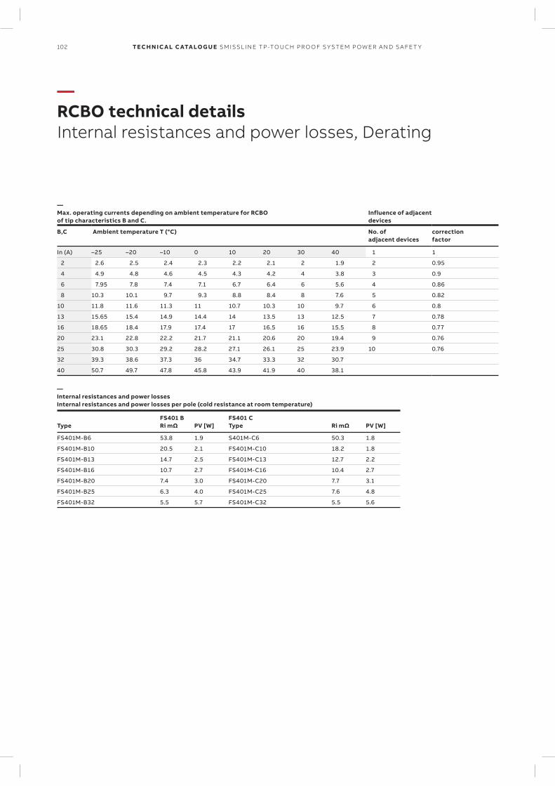
102 TECH N I C A L C ATA LO G U E SM ISSL I N E TP -TO U CH PR O O F S Y S TEM P OW ER A N D S A FE T Y
—RCBO technical detailsInternal resistances and power losses, Derating
—Max. operating currents depending on ambient temperature for RCBO of tip characteristics B and C.
Influence of adjacent devices
B,C Ambient temperature T (°C) No. of adjacent devices
correction factor
In (A) –25 –20 –10 0 10 20 30 40 1 1
2 2.6 2.5 2.4 2.3 2.2 2.1 2 1.9 2 0.95
4 4.9 4.8 4.6 4.5 4.3 4.2 4 3.8 3 0.9
6 7.95 7.8 7.4 7.1 6.7 6.4 6 5.6 4 0.86
8 10.3 10.1 9.7 9.3 8.8 8.4 8 7.6 5 0.82
10 11.8 11.6 11.3 11 10.7 10.3 10 9.7 6 0.8
13 15.65 15.4 14.9 14.4 14 13.5 13 12.5 7 0.78
16 18.65 18.4 17.9 17.4 17 16.5 16 15.5 8 0.77
20 23.1 22.8 22.2 21.7 21.1 20.6 20 19.4 9 0.76
25 30.8 30.3 29.2 28.2 27.1 26.1 25 23.9 10 0.76
32 39.3 38.6 37.3 36 34.7 33.3 32 30.7
40 50.7 49.7 47.8 45.8 43.9 41.9 40 38.1
—Internal resistances and power lossesInternal resistances and power losses per pole (cold resistance at room temperature)
Type FS401 BRi mΩ
PV [W]
FS401 CType Ri mΩ
PV [W]
FS401M-B6 53.8 1.9 S401M-C6 50.3 1.8
FS401M-B10 20.5 2.1 FS401M-C10 18.2 1.8
FS401M-B13 14.7 2.5 FS401M-C13 12.7 2.2
FS401M-B16 10.7 2.7 FS401M-C16 10.4 2.7
FS401M-B20 7.4 3.0 FS401M-C20 7.7 3.1
FS401M-B25 6.3 4.0 FS401M-C25 7.6 4.8
FS401M-B32 5.5 5.7 FS401M-C32 5.5 5.6
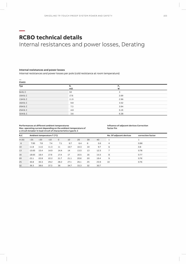
103SM ISSL I N E TP -TO U CH PR O O F S Y S TEM P OW ER A N D S A FE T Y
—RCBO technical detailsInternal resistances and power losses, Derating
Internal resistances and power lossesInternal resistances and power losses per pole (cold resistance at room temperature)
—FS403
Typ Ri
mΩPv
W
6A B, C 50 3
10A B, C 17.6 2.69
13A B, C 11.9 2.96
16A B, C 9.8 3.52
20A B, C 7.3 3.94
25A B, C 4.8 5.19
32A B, C 3.6 6.38
Performances at different ambient temperatures Max. operating current depending on the ambient temperature of a circuit-breaker in load circuit of characteristics type B, C
Influence of adjacent devices Correction factor Fm
B,C Ambient temperature T (°C) No. Of adjacent devices correction factor
In (A) –25 –20 –10 0 10 20 30 40 1 1
6 7.95 7.8 7.4 7.1 6.7 6.4 6 5.6 4 0.86
10 11.8 11.6 11.3 11 10.7 10.3 10 9.7 6 0.8
13 15.65 15.4 14.9 14.4 14 13.5 13 12.5 7 0.78
16 18.65 18.4 17.9 17.4 17 16.5 16 15.5 8 0.77
20 23.1 22.8 22.2 21.7 21.1 20.6 20 19.4 9 0.76
25 30.8 30.3 29.2 28.2 27.1 26.1 25 23.9 10 0.76
32 39.3 38.6 37.3 36 34.7 33.3 32 30.7
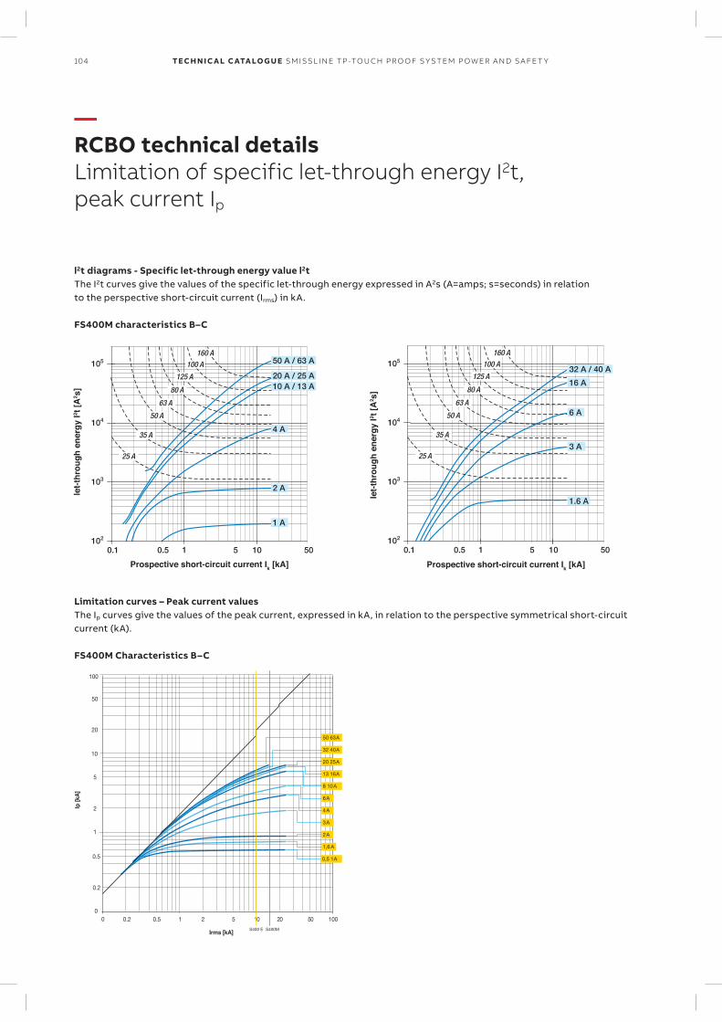
104 TECH N I C A L C ATA LO G U E SM ISSL I N E TP -TO U CH PR O O F S Y S TEM P OW ER A N D S A FE T Y
—RCBO technical detailsLimitation of specific let-through energy I2t, peak current Ip
Prospective short-circuit current Ik [kA]
let-
thro
ug
h e
ner
gy
I2 t [
A2 s
]
Prospective short-circuit current Ik [kA]
let-
thro
ug
h e
ner
gy
I2 t [
A2 s
]
l2t diagrams - Specific let-through energy value l2tThe I2t curves give the values of the specific let-through energy expressed in A2s (A=amps; s=seconds) in relation to the per spective short-circuit current (Irms) in kA.
FS400M characteristics B–C
Ip [k
A]
10
0
20
50
0.2
0.5
100
0
Irms [kA]
0.2 0.5 1 2 5 10 20 50 100
1
2
5
50 63 A
32 40 A
20 25 A
13 16 A
8 10 A
6 A
0,5 1 A
3 A
2 A
1,6 A
4 A
S400 E S400M
Limitation curves – Peak current valuesThe Ip curves give the values of the peak current, expressed in kA, in relation to the perspective symmetrical short-circuit current (kA).
FS400M Characteristics B–C
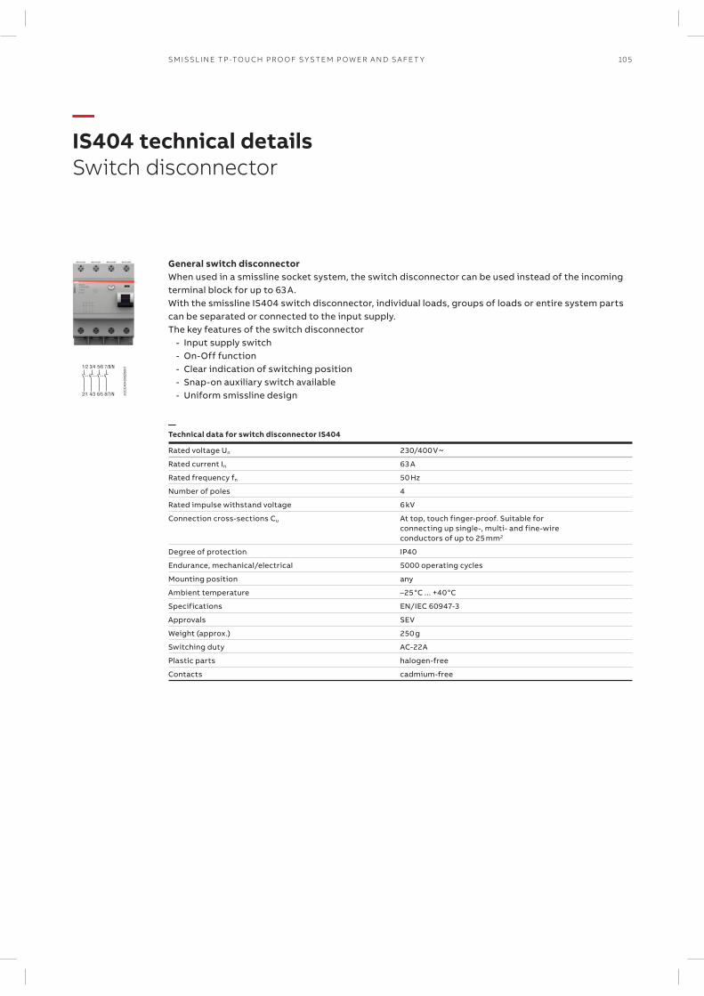
105SM ISSL I N E TP -TO U CH PR O O F S Y S TEM P OW ER A N D S A FE T Y
—IS404 technical detailsSwitch disconnector
1/2 3/4
2/1 4/3
5/6 7/8/N
6/5 8/7/N 2CC
C40
4030
Z00
01
General switch disconnectorWhen used in a smissline socket system, the switch disconnector can be used instead of the incoming terminal block for up to 63 A. With the smissline IS404 switch disconnector, individual loads, groups of loads or entire system parts can be separated or connected to the input supply.The key features of the switch disconnector
- Input supply switch - On-Off function - Clear indication of switching position - Snap-on auxiliary switch available - Uniform smissline design
—Technical data for switch disconnector IS404
Rated voltage Un 230/400 V ~
Rated current In 63 A
Rated frequency fn 50 Hz
Number of poles 4
Rated impulse withstand voltage 6 kV
Connection cross-sections Cu At top, touch finger-proof. Suitable forconnecting up single-, multi- and fine-wireconductors of up to 25 mm2
Degree of protection IP40
Endurance, mechanical/electrical 5000 operating cycles
Mounting position any
Ambient temperature –25°C ... +40°C
Specifications EN/IEC 60947-3
Approvals SEV
Weight (approx.) 250 g
Switching duty AC-22A
Plastic parts halogen-free
Contacts cadmium-free
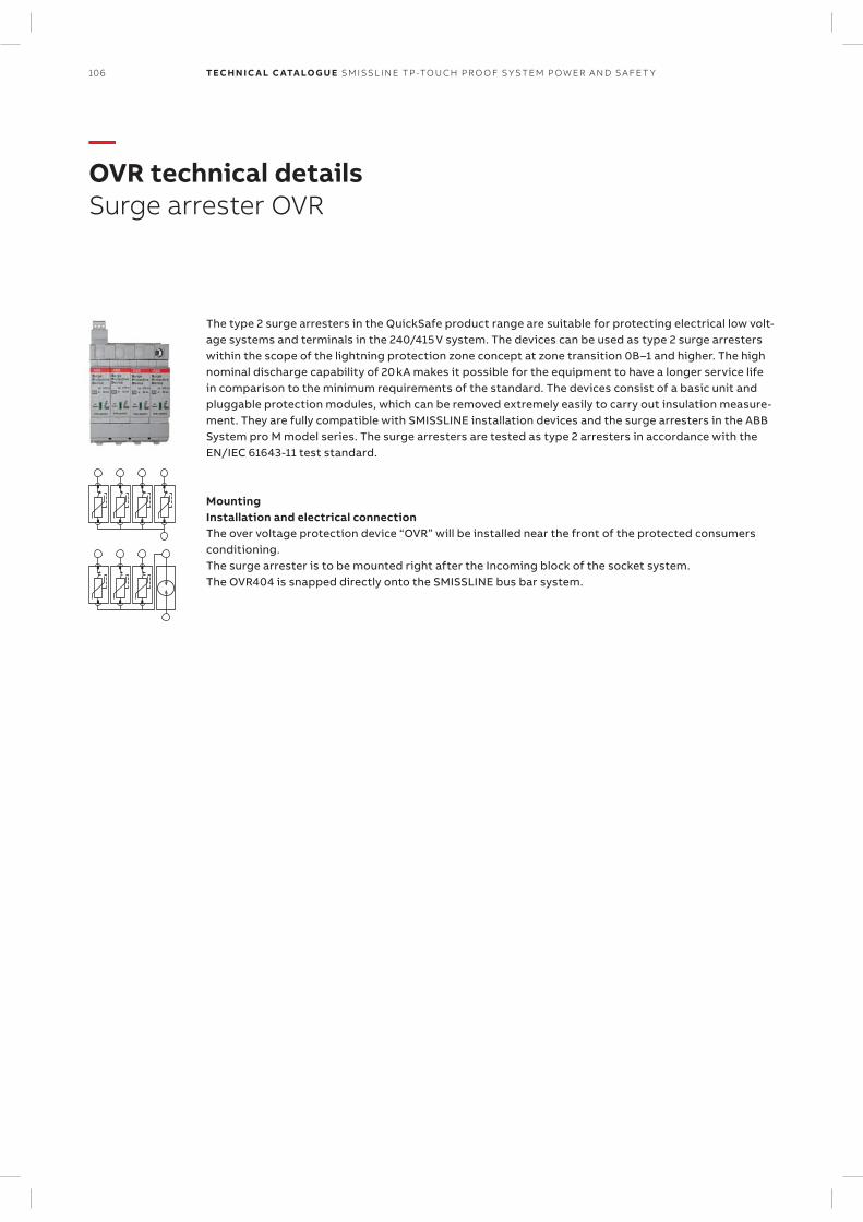
106 TECH N I C A L C ATA LO G U E SM ISSL I N E TP -TO U CH PR O O F S Y S TEM P OW ER A N D S A FE T Y
—OVR technical detailsSurge arrester OVR
The type 2 surge arresters in the QuickSafe product range are suitable for protecting electrical low volt-age systems and terminals in the 240/415 V system. The devices can be used as type 2 surge arresters within the scope of the lightning protection zone concept at zone tran sition 0B–1 and higher. The high nominal discharge capability of 20 kA makes it possible for the equipment to have a longer service life in comparison to the minimum requirements of the standard. The devices consist of a basic unit and pluggable protection modules, which can be removed extremely easily to carry out insulation measure-ment. They are fully compatible with SMISSLINE installation devices and the surge arresters in the ABB System pro M model series. The surge arresters are tested as type 2 arresters in accordance with the EN/IEC 61643-11 test standard.
MountingInstallation and electrical connectionThe over voltage protection device “OVR” will be installed near the front of the protected consumers conditioning. The surge arrester is to be mounted right after the Incoming block of the socket system. The OVR404 is snapped directly onto the SMISSLINE bus bar system.
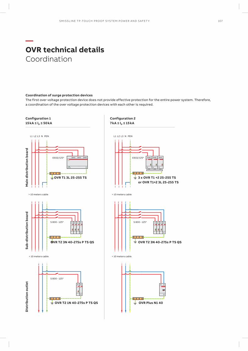
107SM ISSL I N E TP -TO U CH PR O O F S Y S TEM P OW ER A N D S A FE T Y
—OVR technical detailsCoordination
Coordination of surge protection devicesThe first over voltage protection device does not provide effective protection for the entire power system. Therefore, a coordination of the over voltage protection devices with each other is required.
OVR T1
OVR T2 OVR T2 OVR T2 OVR T2
OVR T2 OVR T2
OVR T2 OVR T2 OVR T2 OVR T2
Mai
n d
istr
ibut
ion
boa
rd
L1 L1L2 L2L3 L3N NPEN PEN
Sub
-dis
trib
utio
n b
oard
Dis
trib
utio
n o
utle
t
Configuration 115 kA ≤ Ip ≤ 50 kA
Configuration 27 kA ≤ Ip ≤ 15 kA
E933/125* E933/125*
S 800 - 125* S 800 - 125*
S 800 - 125*
OVR T1 3L 25-255 TS 3 x OVR T1 +2 25-255 TSor OVR T1+2 3L 25-255 TS
OVR T2 3N 40-275s P TS QS
OVR T2 1N 40-275s P TS QS
OVR T2 3N 40-275s P TS QS
OVR Plus N1 40
> 10 meters cable
> 10 meters cable
> 10 meters cable
> 10 meters cable
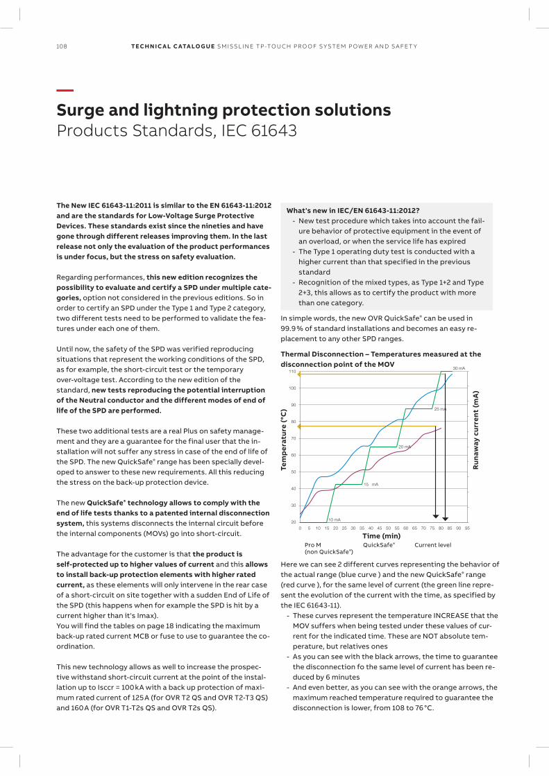
108 TECH N I C A L C ATA LO G U E SM ISSL I N E TP -TO U CH PR O O F S Y S TEM P OW ER A N D S A FE T Y
—Surge and lightning protection solutionsProducts Standards, IEC 61643
The New IEC 61643-11:2011 is similar to the EN 61643-11:2012 and are the standards for Low-Voltage Surge Protective Devices. These standards exist since the nineties and have gone through different releases improving them. In the last release not only the evaluation of the product performances is under focus, but the stress on safety evaluation.
Regarding performances, this new edition recognizes the possibility to evaluate and certify a SPD under multiple cate-gories, option not considered in the previous editions. So in order to certify an SPD under the Type 1 and Type 2 category, two different tests need to be performed to validate the fea-tures under each one of them.
Until now, the safety of the SPD was verified reproducing situations that represent the working conditions of the SPD, as for example, the short-circuit test or the temporary over-voltage test. According to the new edition of the standard, new tests reproducing the potential interruption of the Neutral conductor and the different modes of end of life of the SPD are performed.
These two additional tests are a real Plus on safety manage-ment and they are a guarantee for the final user that the in-stallation will not suffer any stress in case of the end of life of the SPD. The new QuickSafe® range has been specially devel-oped to answer to these new requirements. All this reducing the stress on the back-up protection device.
The new QuickSafe® technology allows to comply with the end of life tests thanks to a patented internal disconnection system, this systems disconnects the internal circuit before the internal components (MOVs) go into short-circuit.
The advantage for the customer is that the product is self-protected up to higher values of current and this allows to install back-up protection elements with higher rated current, as these elements will only intervene in the rear case of a short-circuit on site together with a sudden End of Life of the SPD (this happens when for example the SPD is hit by a current higher than it's Imax). You will find the tables on page 18 indicating the maximum back-up rated current MCB or fuse to use to guarantee the co-ordination.
This new technology allows as well to increase the prospec-tive withstand short-circuit current at the point of the instal-lation up to Isccr = 100 kA with a back up protection of maxi-mum rated current of 125 A (for OVR T2 QS and OVR T2-T3 QS) and 160 A (for OVR T1-T2s QS and OVR T2s QS).
Here we can see 2 different curves representing the behavior of the actual range (blue curve ) and the new QuickSafe® range (red curve ), for the same level of current (the green line repre-sent the evolution of the current with the time, as specified by the IEC 61643-11).
- These curves represent the temperature INCREASE that the MOV suffers when being tested under these values of cur-rent for the indicated time. These are NOT absolute tem-perature, but relatives ones
- As you can see with the black arrows, the time to guarantee the disconnection fo the same level of current has been re-duced by 6 minutes
- And even better, as you can see with the orange arrows, the maximum reached temperature required to guarantee the disconnection is lower, from 108 to 76 °C.
Thermal Disconnection – Temperatures measured at the disconnection point of the MOV
Run
away
cur
rent
(mA
)
200 5 10 15 20
10 mA
15 mA
20 mA
25 mA
30 mA
25 30 35 40 45 50 55 60 65 70 75 80 85 90 95
30
40
50
60
70
80
90
100
110
Tem
per
atur
e (°
C)
Time (min)Pro M (non QuickSafe®)
QuickSafe® Current level
In simple words, the new OVR QuickSafe® can be used in 99.9 % of standard installations and becomes an easy re-placement to any other SPD ranges.
What's new in IEC/EN 61643-11:2012? - New test procedure which takes into account the fail-
ure behavior of protective equipment in the event of an overload, or when the service life has expired
- The Type 1 operating duty test is conducted with a higher current than that specified in the previous standard
- Recognition of the mixed types, as Type 1+2 and Type 2+3, this allows as to certify the product with more than one category.
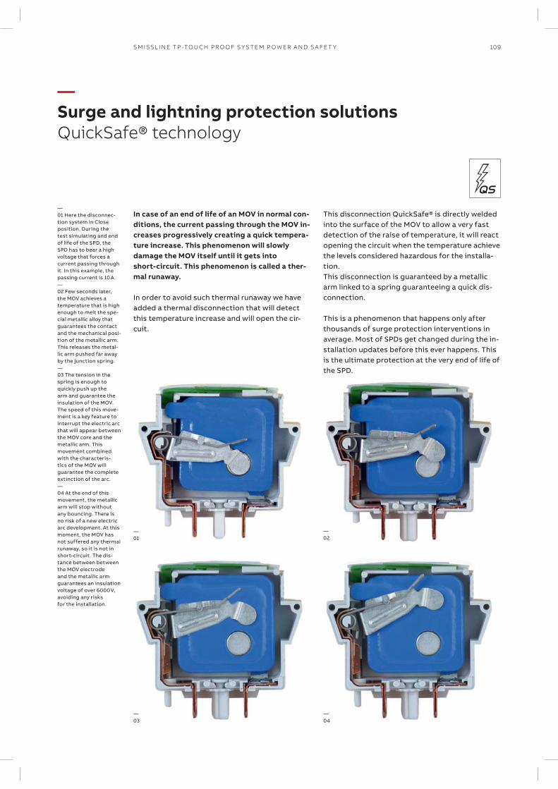
109SM ISSL I N E TP -TO U CH PR O O F S Y S TEM P OW ER A N D S A FE T Y
In case of an end of life of an MOV in normal con-ditions, the current passing through the MOV in-creases progressively creating a quick tempera-ture increase. This phenomenon will slowly damage the MOV itself until it gets into short-circuit. This phenomenon is called a ther-mal runaway.
In order to avoid such thermal runaway we have added a thermal disconnection that will detect this temperature increase and will open the cir-cuit.
This disconnection QuickSafe® is directly welded into the surface of the MOV to allow a very fast detection of the raise of temperature, it will react opening the circuit when the temperature achieve the levels considered hazardous for the installa-tion. This disconnection is guaranteed by a metallic arm linked to a spring guaranteeing a quick dis-connection.
This is a phenomenon that happens only after thousands of surge protection interventions in average. Most of SPDs get changed during the in-stallation updates before this ever happens. This is the ultimate protection at the very end of life of the SPD.
—Surge and lightning protection solutionsQuickSafe® technology
—01
—02
—03
—04
—01 Here the disconnec-tion system in Close position. During the test simulating and end of life of the SPD, the SPD has to bear a high voltage that forces a current passing through it. In this example, the passing current is 10 A.—02 Few seconds later, the MOV achieves a temperature that is high enough to melt the spe-cial metallic alloy that guarantees the contact and the mechanical posi-tion of the metallic arm. This releases the metal-lic arm pushed far away by the junction spring.—03 The tension in the spring is enough to quickly push up the arm and guarantee the insulation of the MOV. The speed of this move-ment is a key feature to interrupt the electric arc that will appear between the MOV core and the metallic arm. This movement combined with the characteris-tics of the MOV will guarantee the complete extinction of the arc.—04 At the end of this movement, the metallic arm will stop without any bouncing. There is no risk of a new electric arc development. At this moment, the MOV has not suffered any thermal runaway, so it is not in short-circuit. The dis-tance between between the MOV electrode and the metallic arm guarantees an insulation voltage of over 6000 V, avoiding any risks for the installation.

110 TECH N I C A L C ATA LO G U E SM ISSL I N E TP -TO U CH PR O O F S Y S TEM P OW ER A N D S A FE T Y
End-of-life indicator standard SPD
Normal End-of-life
NOTE:Pluggable surge protective device cartridges have a foolproof system (Neutral cartridges different to Phase cartridges) preventing in-correct operations when replacing a cartridge.
End of life indicator of the standard surge protective deviceThis option enables indication of the surge protective device state via a mechanical indicator which changes from green to red as the surge protective device comes to end-of-life. When this occurs, the surge protective device must be changed as protection is no longer guaranteed.
Technical features of the integrated auxiliary contact - Contacts information: Normally-opened (NO)/Normal-
ly-closed (NC) - Min. load: 12 V DC – 10 mA - Max. load: 250 V AC – 1 A - Connection cross-section: 1.5 mm².
PluggableThe pluggable feature of ABB surge protective devices facili-tates maintenance. Should one or more worn cartridges need to be replaced, the electrical circuit does not have to be iso-lated nor do the wires have to be removed.
Auxiliary contact (TS)This function, achieved by wiring a 3-point 1 A volt-free con-tact, enables the operational state of the surge protective de-vice to be checked remotely (maintenance premises). For standard products, the TS changes status when the cartridge needs to be replace, protection is not guaranteed. On prod-ucts fitting the Safety Reserve (s) system, it indicates that one component of the cartridge is damaged, but the protec-tion is still guaranteed.
NOTE:A faulty surge protective device does not interrupt conti-nuity of service (if wired such that priority is given to con-tinuity of service), it simply disconnects itself. But, the equipment is no longer protected.
Red Replace
Surge protective device fitted with the auxiliary contact option
Wiring schematic
No. of poles: 4
QuickSafe® technology
OVR404 3N 40-275 P TS QS
Max. operating voltage Uc
Phases:
3N 3phases – neutral; for TT and TN-S net
4L 4 poles; for TN-S net
Max. discharge current Imax (8/20) 40kA
P: pluggable device (Cartriges)
TS: Auxiliary contact
—Surge and lightning protection solutionsSelection of surge protective devices
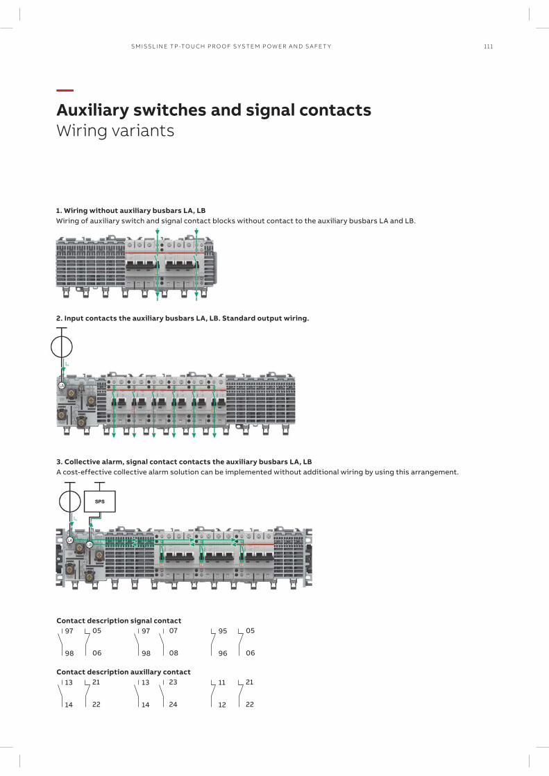
111SM ISSL I N E TP -TO U CH PR O O F S Y S TEM P OW ER A N D S A FE T Y
1. Wiring without auxiliary busbars LA, LBWiring of auxiliary switch and signal contact blocks without contact to the auxiliary busbars LA and LB.
2. Input contacts the auxiliary busbars LA, LB. Standard output wiring.
3. Collective alarm, signal contact contacts the auxiliary busbars LA, LBA cost-effective collective alarm solution can be implemented without additional wiring by using this arrangement.
Contact description signal contact
Contact description auxillary contact
97
98
13
14
97
98
13
14
95
96
11
12
05
06
21
22
07
08
23
24
05
06
21
22
—Auxiliary switches and signal contactsWiring variants
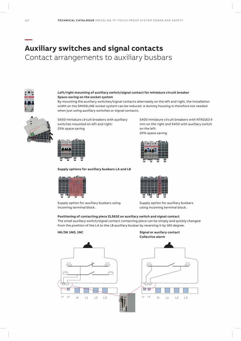
112 TECH N I C A L C ATA LO G U E SM ISSL I N E TP -TO U CH PR O O F S Y S TEM P OW ER A N D S A FE T Y
Left/right mounting of auxiliary switch/signal contact for miniature circuit breakerSpace-saving on the socket systemBy mounting the auxiliary switches/signal contacts alternately on the left and right, the installation width on the SMISSLINE socket system can be reduced. A dummy housing is therefore not needed when just using auxiliary switches or signal contacts.
S400 miniature circuit breakers with auxiliary switches mounted on left and right: 25% space saving
Supply options for auxiliary busbars LA and LB
Supply option for auxiliary busbars using incoming terminal block.
Supply option for auxiliary busbars using incoming terminal block.
Positioning of contacting piece ZLS632 on auxiliary switch and signal contactThe small auxiliary switch/signal contact contacting piece can be simply and quickly changed from the position of the LA to the LB auxiliary busbar by reversing it by 180 degree.
HK/SK 1NO, 1NC Signal or auxilary contact Collective alarm
S400 miniature circuit breakers with NT40163 9 mm on the right and S400 with auxiliary switch on the left: 20% space saving
LA LB N L1 L2 L3 LA LB N L1 L2 L3
—Auxiliary switches and signal contactsContact arrangements to auxiliary busbars
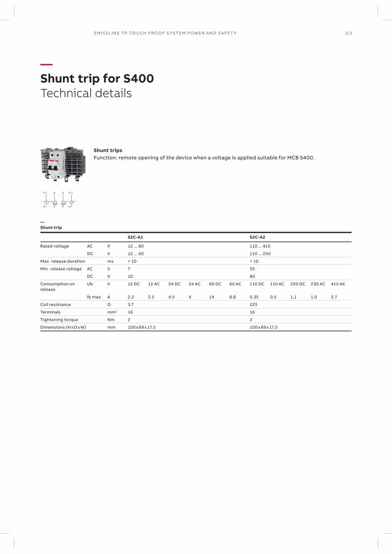
113SM ISSL I N E TP -TO U CH PR O O F S Y S TEM P OW ER A N D S A FE T Y
1
2
C1
C2
1
2
C1
C2
—Shunt trip
S2C-A1 S2C-A2
Rated voltage AC V 12 ... 60 110 ... 415
DC V 12 ... 60 110 ... 250
Max. release duration ms < 10 < 10
Min. release voltage AC V 7 55
DC V 10 80
Consumption on release
Ub V 12 DC 12 AC 24 DC 24 AC 60 DC 60 AC 110 DC 110 AC 220 DC 230 AC 415 AC
lb max A 2.2 2.5 4.5 5 14 8.8 0.35 0.5 1.1 1.0 2.7
Coil resistance Ω 3.7 225
Terminals mm2 16 16
Tightening torque Nm 2 2
Dimensions (H x D x W) mm 100 x 69 x 17.5 100 x 69 x 17.5
Shunt tripsFunction: remote opening of the device when a voltage is applied suitable for MCB S400.
—Shunt trip for S400Technical details
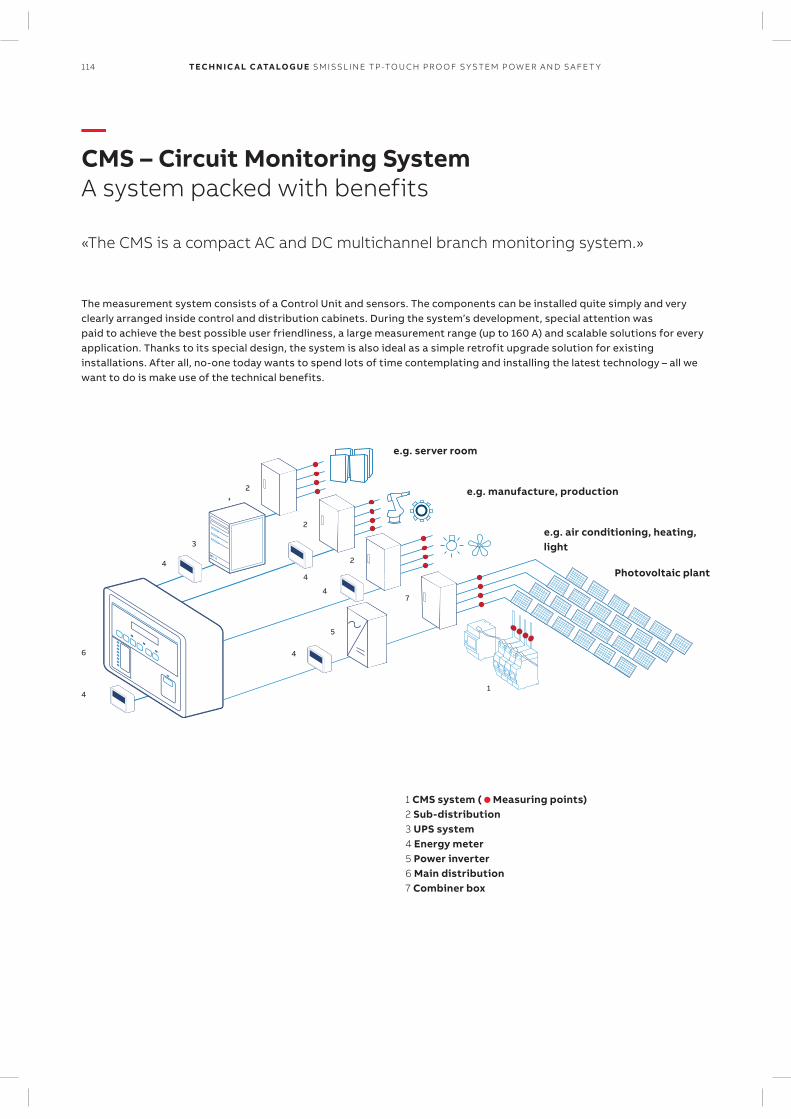
114 TECH N I C A L C ATA LO G U E SM ISSL I N E TP -TO U CH PR O O F S Y S TEM P OW ER A N D S A FE T Y
The measurement system consists of a Control Unit and sensors. The components can be installed quite simply and very clearly arranged inside control and distribution cabinets. During the system’s development, special attention was paid to achieve the best possible user friendliness, a large measurement range (up to 160 A) and scalable solutions for every application. Thanks to its special design, the system is also ideal as a simple retrofit upgrade solution for existing installations. After all, no-one today wants to spend lots of time contemplating and installing the latest technology – all we want to do is make use of the technical benefits.
—CMS – Circuit Monitoring SystemA system packed with benefits
«The CMS is a compact AC and DC multichannel branch monitoring system.»
6
5
4
4
4
4
3
7
2
2
2
1
4
e.g. server room
e.g. manufacture, production
e.g. air conditioning, heating, light
Photovoltaic plant
1 CMS system ( Measuring points)2 Sub-distribution3 UPS system 4 Energy meter5 Power inverter6 Main distribution 7 Combiner box

115SM ISSL I N E TP -TO U CH PR O O F S Y S TEM P OW ER A N D S A FE T Y
Minimum space requirement Small, smaller, CMS – everything needed for effective measuring has been accommodated in the width of a sugar cube
Always retrofittable and upgradeableThe system can be supplemented or modified at any time as it is extremely flexible and modular.Retrofitting is possible sensor by sensor and is key for brownfield extension.
User-friendly commissioningConfiguring can be this smart: Thanks to the intuitive operating concept, the system can be set up and made ready for measuring in a matter of minutes. The integrated Web UI does not need any external software.
One sensor for all types of currentDirect current, alternating current or mixed current, the CMS sensors measure everything in a huge measuring range of up to 160A.
Very simple installationThe sensors are mounted in no time thanks to a simple and tidy bus wiring. No special tools are needed for the entire connection process.
Maximum security and reliability Protocols include Modbus RTU, TCP and SNMP v1, 2 & 3. Using the new encrypted SNMPv3, utmost data security is guaranteed. The con-tactless measuring process rules out potential sources of error right from the start. The negligible amount of wiring required ensures maximum system stability.
—CMS – Circuit Monitoring SystemA system packed with benefits
This is the sign of success!
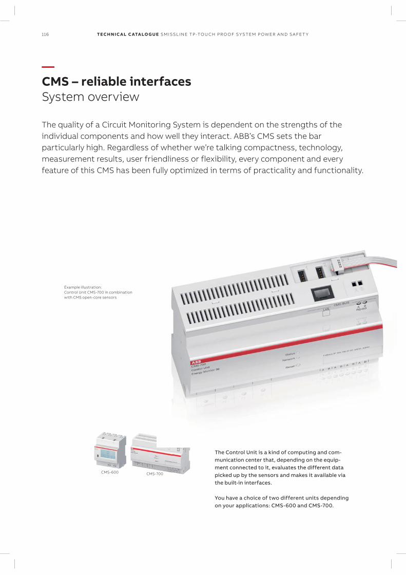
116 TECH N I C A L C ATA LO G U E SM ISSL I N E TP -TO U CH PR O O F S Y S TEM P OW ER A N D S A FE T Y
CMS-600 CMS-700
Control UnitsThe Control Unit is a kind of computing and com-munication center that, depending on the equip-ment connected to it, evaluates the different data picked up by the sensors and makes it available via the built-in interfaces.
You have a choice of two different units depending on your applications: CMS-600 and CMS-700.
CMS bus interface A bus interface allows up to 32 sensors to be connected to the Control Unit.
Example illustration: Control Unit CMS-700 in combination with CMS open-core sensors
—CMS – reliable interfacesSystem overview
The quality of a Circuit Monitoring System is dependent on the strengths of the individual components and how well they interact. ABB’s CMS sets the bar particularly high. Regardless of whether we’re talking compactness, technology, measurement results, user friendliness or flexibility, every component and every feature of this CMS has been fully optimized in terms of practicality and functionality.

117SM ISSL I N E TP -TO U CH PR O O F S Y S TEM P OW ER A N D S A FE T Y
—CMS – reliable interfacesSystem overview
SensorsThe CMS sensors form the heart of the sys-tem and they can be mounted everywhere without any problem. Initializing the sen-sors is also child’s play, with the desired identifier being assigned to each individual sensor via the Control Unit in just a few sim-ple steps. The entire configuration and com-missioning procedure takes just a matter of minutes. All measurement functions are available immediately following initializa-tion.
Serial interfaces Depending on the unit, numerous interfaces and protocols are available to ensure smooth network implementa-tion: RS485 (Modbus RTU), LAN (TCP/IP and Mod-bus TCP), SNMP v1/v2 and encrypted v3.
Thanks to the built-in web server, an internet browser or a free Android or iOS app can be used to visualize the values measured. What’s more, the measured values can also be exported to CSV files.
Connection technology Connecting the sensors to the Control Unit is extremely simple and requires no special tools. All sensors are connected to the Control Unit by means of a flexible flat cable and insulation displacement connectors. The position-ing of sensors is fully customizable so that they sit exactly where a measurement is required.
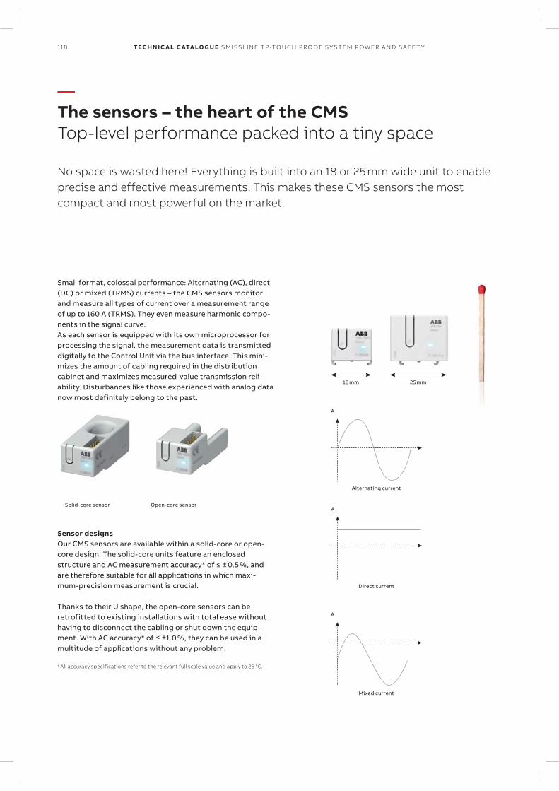
118 TECH N I C A L C ATA LO G U E SM ISSL I N E TP -TO U CH PR O O F S Y S TEM P OW ER A N D S A FE T Y
—The sensors – the heart of the CMSTop-level performance packed into a tiny space
No space is wasted here! Everything is built into an 18 or 25 mm wide unit to enable precise and effective measurements. This makes these CMS sensors the most compact and most powerful on the market.
A
A
A
18 mm
Direct current
Mixed current
25 mm
Sensor designs Our CMS sensors are available within a solid-core or open-core design. The solid-core units feature an enclosed structure and AC measurement accuracy* of ≤ ± 0.5 %, and are therefore suitable for all applications in which maxi-mum-precision measurement is crucial.
Thanks to their U shape, the open-core sensors can be retrofitted to existing installations with total ease without having to disconnect the cabling or shut down the equip-ment. With AC accuracy* of ≤ ±1.0 %, they can be used in a multitude of applications without any problem.
* All accuracy specifications refer to the relevant full scale value and apply to 25 °C.
Solid-core sensor Open-core sensor
Small format, colossal performance: Alternating (AC), direct (DC) or mixed (TRMS) currents – the CMS sensors monitor and measure all types of current over a measurement range of up to 160 A (TRMS). They even measure harmonic compo-nents in the signal curve. As each sensor is equipped with its own microprocessor for processing the signal, the measurement data is transmitted digitally to the Control Unit via the bus interface. This mini-mizes the amount of cabling required in the distribution cabinet and maximizes measured-value transmission reli-ability. Disturbances like those experienced with analog data now most definitely belong to the past.
Alternating current
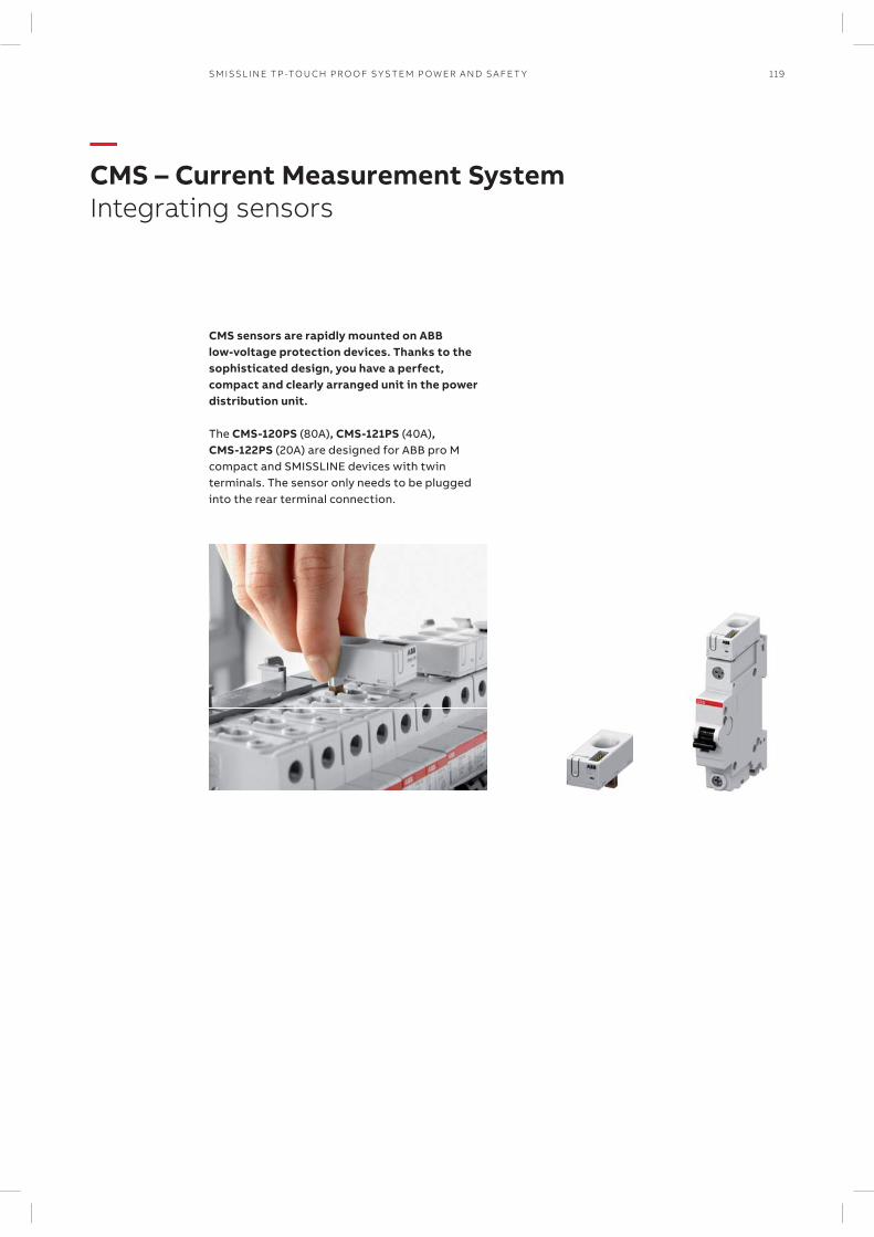
119SM ISSL I N E TP -TO U CH PR O O F S Y S TEM P OW ER A N D S A FE T Y
CMS sensors are rapidly mounted on ABB low-voltage protection devices. Thanks to the sophisticated design, you have a perfect, compact and clearly arranged unit in the power distribution unit.
The CMS-120PS (80A), CMS-121PS (40A), CMS-122PS (20A) are designed for ABB pro M compact and SMISSLINE devices with twin ter minals. The sensor only needs to be plugged into the rear terminal connection.
—CMS – Current Measurement SystemIntegrating sensors
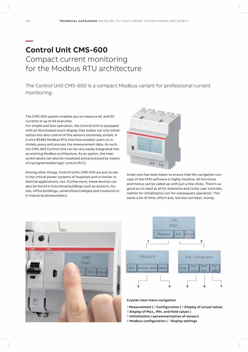
120 TECH N I C A L C ATA LO G U E SM ISSL I N E TP -TO U CH PR O O F S Y S TEM P OW ER A N D S A FE T Y
—Control Unit CMS-600Compact current monitoring for the Modbus RTU architecture
The Control Unit CMS-600 is a compact Modbus variant for professional current monitoring.
The CMS-600 system enables you to measure AC and DC currents in up to 64 branches. For simple and fast operation, the Control Unit is equipped with an illuminated touch display that makes not only initial-ization but also control of the sensors extremely simple. A 2-wire RS485 Modbus RTU interface enables users to re-motely query and process the measurement data. As such, the CMS-600 Control Unit can be very easily integrated into an existing Modbus architecture. As an option, the mea-sured values can also be visualized and processed by means of a programmable logic control (PLC).
Among other things, Control Units CMS-600 are put to use in the critical power systems of hospitals and in similar in-dustrial applications, too. Furthermore, these devices can also be found in functional buildings such as airports, ho-tels, office buildings, universities/colleges and museums or in industrial photovoltaics.
1 2
3 4 5 76
Great care has been taken to ensure that the navigation con-cept of the CMS software is highly intuitive. All functions and menus can be called up with just a few clicks. There’s as good as no need at all for extensive and costly user tutorials, neither for initialization nor for subsequent operation. This saves a lot of time, effort and, last but not least, money.
1 Measurement | 2 Configuration | 3 Display of actual values 4 Display of Max., Min. and Hold values | 5 Initialization / parameterization of sensors 6 Modbus configuration | 7 Display settings
Crystal-clear menu navigation
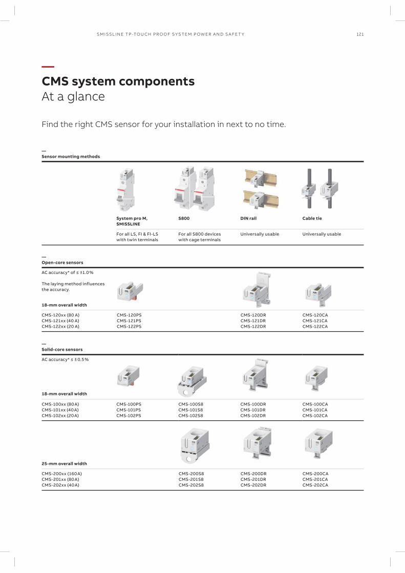
121SM ISSL I N E TP -TO U CH PR O O F S Y S TEM P OW ER A N D S A FE T Y
—CMS system componentsAt a glance
Find the right CMS sensor for your installation in next to no time.
—Sensor mounting methods
System pro M, SMISSLINE
S800 DIN rail Cable tie
For all LS, FI & FI-LS with twin terminals
For all S800 devices with cage terminals
Universally usable Universally usable
—Open-core sensors
AC accuracy* of ≤ ±1.0 % The laying method influences the accuracy.
18-mm overall width
CMS-120xx (80 A) CMS-121xx (40 A) CMS-122xx (20 A)
CMS-120PS CMS-121PS CMS-122PS
CMS-120DR CMS-121DR CMS-122DR
CMS-120CA CMS-121CA CMS-122CA
—Solid-core sensors
AC accuracy* ≤ ± 0.5 %
18-mm overall width
CMS-100xx (80 A) CMS-101xx (40 A) CMS-102xx (20 A)
CMS-100PS CMS-101PS CMS-102PS
CMS-100S8 CMS-101S8 CMS-102S8
CMS-100DR CMS-101DR CMS-102DR
CMS-100CA CMS-101CA CMS-102CA
25-mm overall width
CMS-200xx (160 A) CMS-201xx (80 A) CMS-202xx (40 A)
CMS-200S8 CMS-201S8 CMS-202S8
CMS-200DR CMS-201DR CMS-202DR
CMS-200CA CMS-201CA CMS-202CA
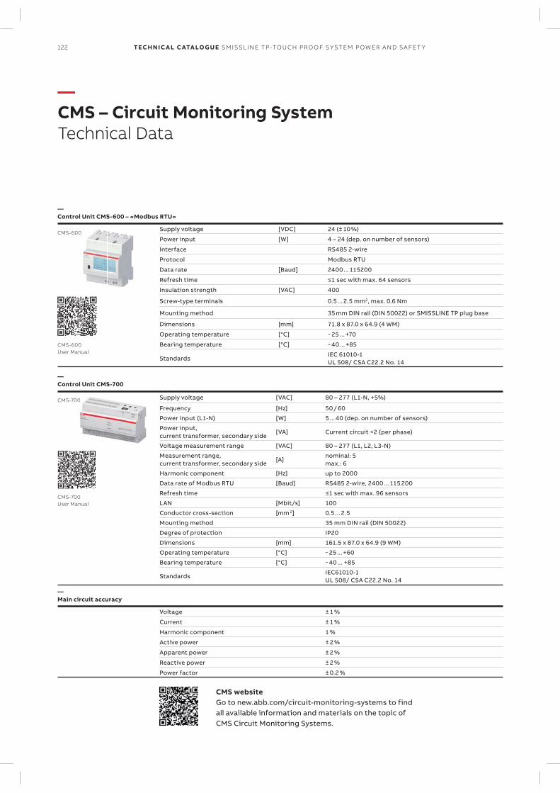
122 TECH N I C A L C ATA LO G U E SM ISSL I N E TP -TO U CH PR O O F S Y S TEM P OW ER A N D S A FE T Y
—CMS – Circuit Monitoring SystemTechnical Data
CMS-600
CMS-700S-700
—Control Unit CMS-600 – «Modbus RTU»
Supply voltage [VDC] 24 (± 10 %)
Power input [W] 4 – 24 (dep. on number of sensors)
Interface RS485 2-wire
Protocol Modbus RTU
Data rate [Baud] 2400 ... 115200
Refresh time ≤1 sec with max. 64 sensors
Insulation strength [VAC] 400
Screw-type terminals 0.5 ... 2.5 mm2, max. 0.6 Nm
Mounting method 35 mm DIN rail (DIN 50022) or SMISSLINE TP plug base
Dimensions [mm] 71.8 x 87.0 x 64.9 (4 WM)
Operating temperature [°C] − 25 ... +70
Bearing temperature [°C] − 40 ... +85
StandardsIEC 61010-1UL 508/ CSA C22.2 No. 14
CMS-700 User Manual
CMS-600 User Manual
—Control Unit CMS-700
Supply voltage [VAC] 80 – 277 (L1-N, +5%)
Frequency [Hz] 50 / 60
Power input (L1-N) [W] 5 ... 40 (dep. on number of sensors)
Power input, current transformer, secondary side
[VA] Current circuit <2 (per phase)
Voltage measurement range [VAC] 80 – 277 (L1, L2, L3-N)
Measurement range, current transformer, secondary side
[A]nominal: 5max.: 6
Harmonic component [Hz] up to 2000
Data rate of Modbus RTU [Baud] RS485 2-wire, 2400 ... 115 200
Refresh time ≤1 sec with max. 96 sensors
LAN [Mbit/s] 100
Conductor cross-section [mm 2] 0.5 ... 2.5
Mounting method 35 mm DIN rail (DIN 50022)
Degree of protection IP20
Dimensions [mm] 161.5 x 87.0 x 64.9 (9 WM)
Operating temperature [°C] − 25 ... +60
Bearing temperature [°C] − 40 ... +85
StandardsIEC61010-1 UL 508/ CSA C22.2 No. 14
—Main circuit accuracy
Voltage ± 1 %
Current ± 1 %
Harmonic component 1 %
Active power ± 2 %
Apparent power ± 2 %
Reactive power ± 2 %
Power factor ± 0.2 %
CMS websiteGo to new.abb.com/circuit-monitoring-systems to find all available information and materials on the topic of CMS Circuit Monitoring Systems.
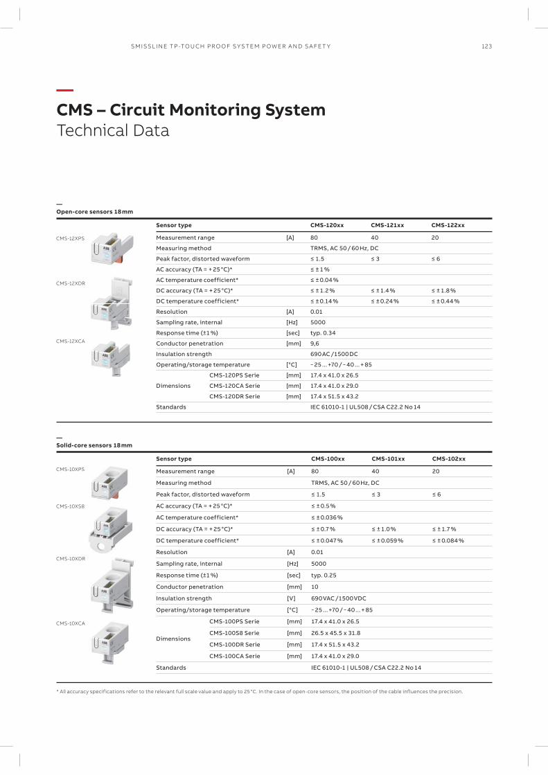
123SM ISSL I N E TP -TO U CH PR O O F S Y S TEM P OW ER A N D S A FE T Y
—CMS – Circuit Monitoring SystemTechnical Data
CMS-10XPS
CMS-10XS8
CMS-10XDR
CMS-12XPS
CMS-12XDR
CMS-12XCA
CMS-10XCA
—Open-core sensors 18 mm
Sensor type CMS-120xx CMS-121xx CMS-122xx
Measurement range [A] 80 40 20
Measuring method TRMS, AC 50 / 60 Hz, DC
Peak factor, distorted waveform ≤ 1.5 ≤ 3 ≤ 6
AC accuracy (TA = + 25 °C)* ≤ ± 1 %
AC temperature coefficient* ≤ ± 0.04 %
DC accuracy (TA = + 25 °C)* ≤ ± 1.2 % ≤ ± 1.4 % ≤ ± 1.8 %
DC temperature coefficient* ≤ ± 0.14 % ≤ ± 0.24 % ≤ ± 0.44 %
Resolution [A] 0.01
Sampling rate, internal [Hz] 5000
Response time (±1 %) [sec] typ. 0.34
Conductor penetration [mm] 9,6
Insulation strength 690 AC /1500 DC
Operating/storage temperature [°C] − 25 ... +70 / − 40 ... + 85
Dimensions
CMS-120PS Serie [mm] 17.4 x 41.0 x 26.5
CMS-120CA Serie [mm] 17.4 x 41.0 x 29.0
CMS-120DR Serie [mm] 17.4 x 51.5 x 43.2
Standards IEC 61010-1 | UL508 / CSA C22.2 No 14
—Solid-core sensors 18 mm
Sensor type CMS-100xx CMS-101xx CMS-102xx
Measurement range [A] 80 40 20
Measuring method TRMS, AC 50 / 60 Hz, DC
Peak factor, distorted waveform ≤ 1.5 ≤ 3 ≤ 6
AC accuracy (TA = + 25 °C)* ≤ ± 0.5 %
AC temperature coefficient* ≤ ± 0.036 %
DC accuracy (TA = + 25 °C)* ≤ ± 0.7 % ≤ ± 1.0 % ≤ ± 1.7 %
DC temperature coefficient* ≤ ± 0.047 % ≤ ± 0.059 % ≤ ± 0.084 %
Resolution [A] 0.01
Sampling rate, internal [Hz] 5000
Response time (±1 %) [sec] typ. 0.25
Conductor penetration [mm] 10
Insulation strength [V] 690 VAC /1500 VDC
Operating/storage temperature [°C] − 25 ... +70 / − 40 ... + 85
Dimensions
CMS-100PS Serie [mm] 17.4 x 41.0 x 26.5
CMS-100S8 Serie [mm] 26.5 x 45.5 x 31.8
CMS-100DR Serie [mm] 17.4 x 51.5 x 43.2
CMS-100CA Serie [mm] 17.4 x 41.0 x 29.0
Standards IEC 61010-1 | UL508 / CSA C22.2 No 14
* All accuracy specifications refer to the relevant full scale value and apply to 25 °C. In the case of open-core sensors, the position of the cable influences the precision.
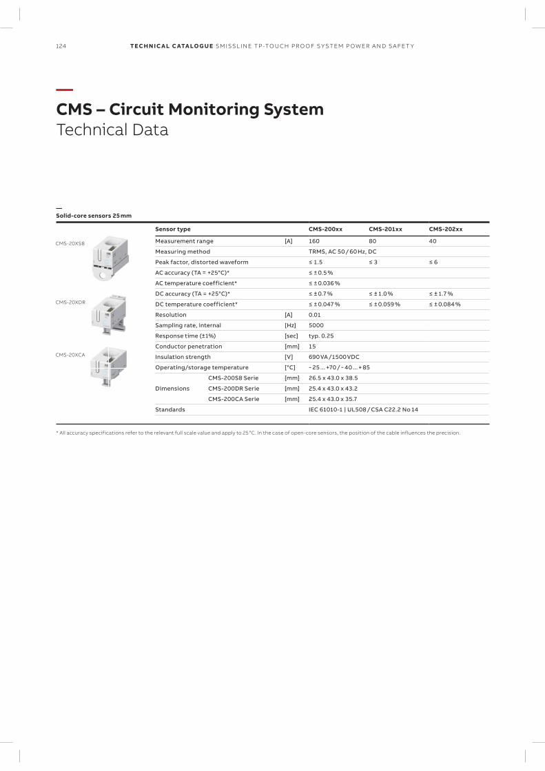
124 TECH N I C A L C ATA LO G U E SM ISSL I N E TP -TO U CH PR O O F S Y S TEM P OW ER A N D S A FE T Y
—CMS – Circuit Monitoring SystemTechnical Data
CMS-20XS8
CMS-20XDR
CMS-20XCA
—Solid-core sensors 25 mm
Sensor type CMS-200xx CMS-201xx CMS-202xx
Measurement range [A] 160 80 40
Measuring method TRMS, AC 50 / 60 Hz, DC
Peak factor, distorted waveform ≤ 1.5 ≤ 3 ≤ 6
AC accuracy (TA = +25°C)* ≤ ± 0.5 %
AC temperature coefficient* ≤ ± 0.036 %
DC accuracy (TA = +25°C)* ≤ ± 0.7 % ≤ ± 1.0 % ≤ ± 1.7 %
DC temperature coefficient* ≤ ± 0.047 % ≤ ± 0.059 % ≤ ± 0.084 %
Resolution [A] 0.01
Sampling rate, internal [Hz] 5000
Response time (±1%) [sec] typ. 0.25
Conductor penetration [mm] 15
Insulation strength [V] 690 VA /1500 VDC
Operating/storage temperature [°C] − 25 ... +70 / − 40 ... + 85
Dimensions
CMS-200S8 Serie [mm] 26.5 x 43.0 x 38.5
CMS-200DR Serie [mm] 25.4 x 43.0 x 43.2
CMS-200CA Serie [mm] 25.4 x 43.0 x 35.7
Standards IEC 61010-1 | UL508 / CSA C22.2 No 14
* All accuracy specifications refer to the relevant full scale value and apply to 25 °C. In the case of open-core sensors, the position of the cable influences the precision.
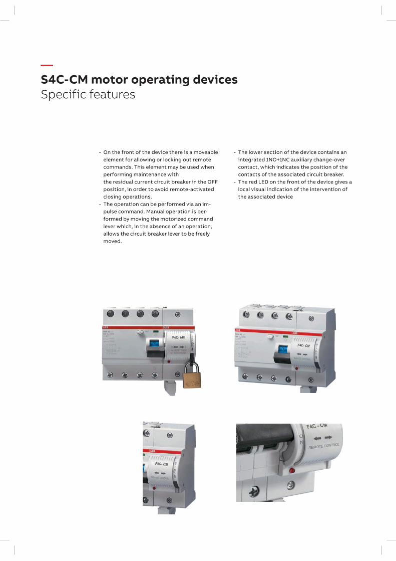
- On the front of the device there is a moveable element for allowing or locking out remote commands. This element may be used when performing maintenance with the residual current circuit breaker in the OFF position, in order to avoid remote-activated closing operations.
- The operation can be performed via an im-pulse command. Manual operation is per-formed by moving the motorized command lever which, in the absence of an operation, allows the circuit breaker lever to be freely moved.
—S4C-CM motor operating devicesSpecific features
- The lower section of the device contains an integrated 1NO+1NC auxiliary change-over contact, which indicates the position of the contacts of the associated circuit breaker.
- The red LED on the front of the device gives a local visual indication of the intervention of the associated device

127SM ISSL I N E TP -TO U CH PR O O F S Y S TEM P OW ER A N D S A FE T Y
— Table of conteantsSMISSLINE TP
128 – 130 Dimension of SMISSLINE
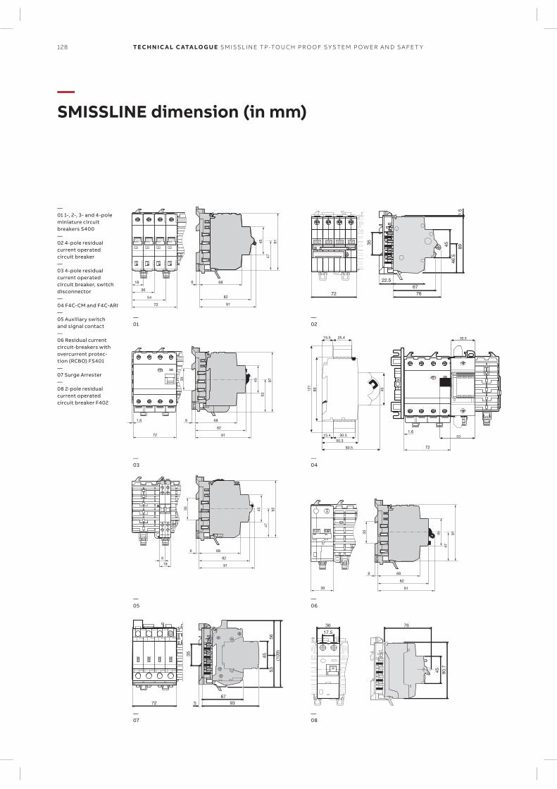
53
9745
72 91
82
6861.6
35
47
9245
18
9
91
82
686
35
54
72
36
18
47
9145
91
82
686
0 OFF 0 OFF 0 OFF 0 OFF
72
22.56776
35 45 891.5
46.5
15.5 25.4
4589121
15.4 30.5
50.3
80.5 72
1.6
35.5
5345 90.7
7617.536
7267
5 93
35 45
(109)
5356
T
O OFF O OFFO OFF
47
9145
36 91
82
686
35
128 TECH N I C A L C ATA LO G U E SM ISSL I N E TP -TO U CH PR O O F S Y S TEM P OW ER A N D S A FE T Y
—SMISSLINE dimension (in mm)
—01 1-, 2-, 3- and 4-pole miniature circuit breakers S400—02 4-pole residual current operated circuit breaker—03 4-pole residual current operated circuit breaker, switch disconnector—04 F4C-CM and F4C-ARI—05 Auxiliary switch and signal contact—06 Residual current circuit-breakers with overcurrent protec-tion (RCBO) FS401—07 Surge Arrester—08 2-pole residual current operated circuit breaker F402
—01
—03
—05
—07
—02
—04
—06
—08
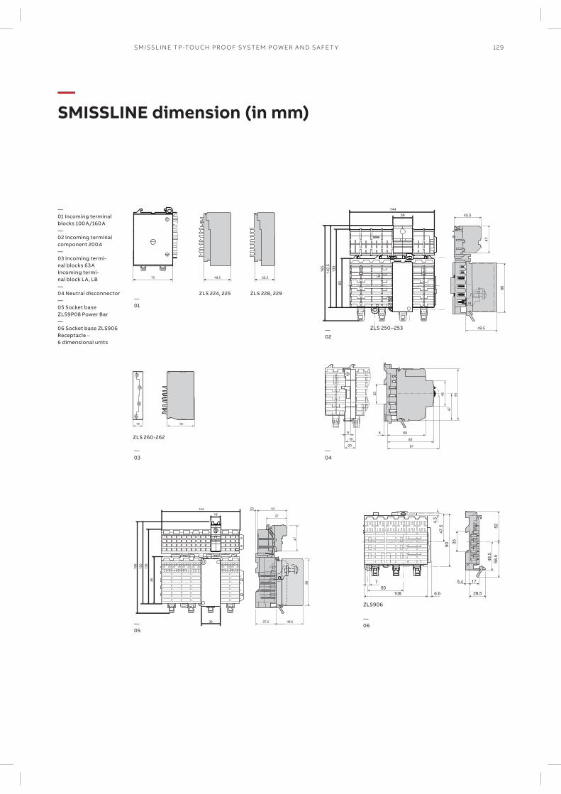
45.5
144
36
47
86
83
133
142.
5
165
49.5
72 49.5 35.5
47
914518
20
9
91
82
686
35
ZLS 224, 225
ZLS 250–253
ZLS 228, 229
18 50
ZLS 260-262
90
4.5
35
52
48.5
58.5
47.5
175.4760
108 6.6 28.5
ZLS906
54
47
37
(2)144
18
86
85
136
150
168
36 49.537.5
129SM ISSL I N E TP -TO U CH PR O O F S Y S TEM P OW ER A N D S A FE T Y
—SMISSLINE dimension (in mm)
—01 Incoming terminal blocks 100 A/160 A—02 Incoming terminal component 200 A—03 Incoming termi-nal blocks 63 AIncoming termi-nal block LA, LB—04 Neutral disconnector—05 Socket base ZLS9P08 Power Bar—06 Socket base ZLS906Receptacle – 6 dimensional units
—01
—03
—05
—02
—04
—06
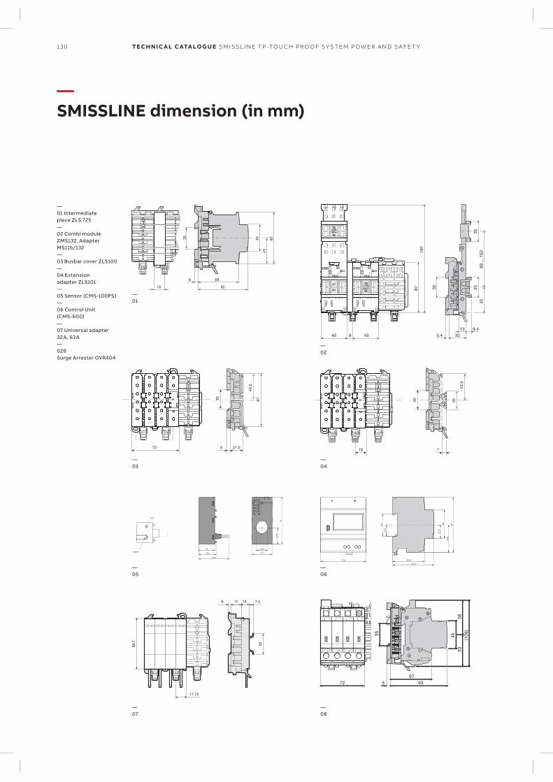
7
35 35
43.5
18
43
8545
18 82
686
35
21.5
35
43.5
87
72 6
71,8
54
78
3,12
53
50,4
64,9
3,34
5,71
14
15,5
26,5
53,41
9,9
17,4
14
LED
Taster
187
35 3535
87
13 9.45.445 459 30
4599
... 1
62
86.7
17.75
17 13 7.56
35
7267
5 93
35 45
(109)
5356
130 TECH N I C A L C ATA LO G U E SM ISSL I N E TP -TO U CH PR O O F S Y S TEM P OW ER A N D S A FE T Y
—SMISSLINE dimension (in mm)
—01 Intermediate piece ZLS 725—02 Combi module ZMS132, Adapter MS116/132—03 Busbar cover ZLS100—04 Extension adapter ZLS101—05 Sensor (CMS-100PS)—06 Control Unit (CMS-600)—07 Universal adapter 32 A, 63 A—028 Surge Arrester OVR404
—01
—03
—05
—07
—02
—04
—06
—08
131SM ISSL I N E TP -TO U CH PR O O F S Y S TEM P OW ER A N D S A FE T Y
— Table of conteantsSMISSLINE TP
132 Approvals and standards
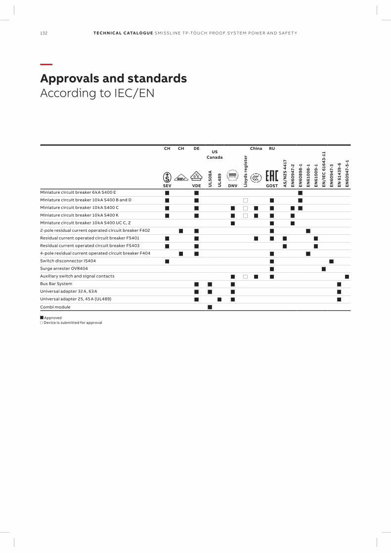
132 TECH N I C A L C ATA LO G U E SM ISSL I N E TP -TO U CH PR O O F S Y S TEM P OW ER A N D S A FE T Y
—Approvals and standardsAccording to IEC/EN
CH CH DEUS
Canada
Lloy
ds
reg
iste
r
China RU
AS/
NZ
S 441
7
EN6094
7-2
EN608
98-1
EN61
008
-1
EN61
009
-1
EN/I
EC 616
43-11
EN6094
7-3
EN 614
39-6
EN6094
7-5
-1
UL5
08A
UL4
89
SEV VDE DNV GOSTMiniature circuit breaker 6 kA S400 E Miniature circuit breaker 10 kA S400 B and D Miniature circuit breaker 10 kA S400 C Miniature circuit breaker 10 kA S400 K Miniature circuit breaker 10 kA S400 UC C, Z 2-pole residual current operated circuit breaker F402 Residual current operated circuit breaker FS401 Residual current operated circuit breaker FS403 4-pole residual current operated circuit breaker F404 Switch disconnector IS404 Surge arrester OVR404 Auxiliary switch and signal contacts Bus Bar System Universal adapter 32 A, 63 A Universal adapter 25, 45 A (UL489)
Combi module
Approved Device is submitted for approval

© Copyright 2017 ABB. All rights reserved. Specifications subject to change without notice. 2C
CC
451
059
C0
203
RE
V B
No
v 20
17
—We reserve the right to make technical changes or modify the contents of this document without prior notice. With re-gard to purchase orders, the agreed par-ticulars shall prevail. ABB AG does not ac-cept any responsibility whatsoever for potential errors or possible lack of infor-mation in this document.
We reserve all rights in this document and in the subject matter and illustrations con-tained therein. Any reproduction, disclo-sure to third parties or utilization of its contents – in whole or in parts – is forbidden without prior written consent of ABB AG. Copyright© 2017 ABBAll rights reserved
—ABB Switzerland Ltd.Low Voltage ProductsFulachstrasse 150CH-8201 SchaffhausenTelefon +41 (0) 58 586 41 11Telefax +41 (0) 58 586 42 22
abb.ch
2CCC451059C0204.indd 2 30.10.17 16:20