SMCube Reference Manual - E4Coder
77
SMCube Reference Manual State Machines for everyday usage Version: 2.0 October 25, 2012
Transcript of SMCube Reference Manual - E4Coder

SMCube Reference Manual
State Machines for everyday usage
Version: 2.0
October 25, 2012

About Evidence S.r.l.
Evidence is a company operating in the field of software for embedded real-time systems.It started in 2002 as a spin-off company of the Real-Time Systems (ReTiS) Lab of theScuola Superiore Sant’Anna (Pisa, Italy). Today, Evidence is a dynamic company havingcollaborations in the field of electronics, telecommunications, automotives, and industrialautomation.
People at Evidence are experts in the domain of embedded and real-time systems, witha deep knowledge on the design and specification flow of embedded software, especiallyfor the embedded market.
Besides providing consultancy services, Evidence also provides: BSPs based on Linuxfor embedded devices, evaluation boards featuring most innovative 8, 16 and 32-bitmicrocontrollers for the embedded market, development tools for making embeddedsoftware development easier, and tools for the schedulability analysis of real-time tasksrunning on your final product.
For more information see: http://www.evidence.eu.com
Contact Info
Evidence Srl,Via Carducci 56Localita Ghezzano56010 S.Giuliano TermePISA Italy
Tel: +39 050 99 11 224Fax: +39 050 99 10 812
For more information about Evidence products, please send an e-mail to the follow-ing address: [email protected]. Other information about the Evidence productline can be found at the Evidence web site at: http://www.evidence.eu.com.
This document is Copyright 2011-2012 Evidence S.r.l.
Information and images contained within this document are copyright and the property of Evidence
S.r.l. All trademarks are hereby acknowledged to be the properties of their respective owners. The
information, text and graphics contained in this document are provided for information purposes only by
Evidence S.r.l. Evidence S.r.l. does not warrant the accuracy, or completeness of the information, text,
and other items contained in this document. Matlab, Simulink, Mathworks are registered trademarks
of Matworks Inc. Microsoft, Windows are registered trademarks of Microsoft Inc. Java is a registered
trademark of Sun Microsystems. in the USA. and other countries, and are used under license. All
other trademarks used are properties of their respective owners. This document has been written using
LATEX.
2

Contents
1. Introduction 91.1. Quick feature list . . . . . . . . . . . . . . . . . . . . . . . . . . . . . . . 101.2. Requirements . . . . . . . . . . . . . . . . . . . . . . . . . . . . . . . . . 101.3. Licensing . . . . . . . . . . . . . . . . . . . . . . . . . . . . . . . . . . . . 111.4. Installation . . . . . . . . . . . . . . . . . . . . . . . . . . . . . . . . . . 111.5. Technical support . . . . . . . . . . . . . . . . . . . . . . . . . . . . . . . 11
2. Semantics behind a SMCube model 122.1. Structure . . . . . . . . . . . . . . . . . . . . . . . . . . . . . . . . . . . 122.2. Syntax . . . . . . . . . . . . . . . . . . . . . . . . . . . . . . . . . . . . . 142.3. Behavior . . . . . . . . . . . . . . . . . . . . . . . . . . . . . . . . . . . . 17
2.3.1. Transitions from simple states . . . . . . . . . . . . . . . . . . . . 182.3.1.1. Action execution order . . . . . . . . . . . . . . . . . . . 182.3.1.2. Transition Joins . . . . . . . . . . . . . . . . . . . . . . 192.3.1.3. Examples . . . . . . . . . . . . . . . . . . . . . . . . . . 19
2.3.2. Superstates of OR type . . . . . . . . . . . . . . . . . . . . . . . . 212.3.2.1. Transitions from a superstate of type OR . . . . . . . . 212.3.2.2. Example . . . . . . . . . . . . . . . . . . . . . . . . . . . 22
2.3.3. Superstates of AND type . . . . . . . . . . . . . . . . . . . . . . . 242.3.3.1. Example . . . . . . . . . . . . . . . . . . . . . . . . . . . 25
3. Integration with ScicosLab 28
4. The SMCube editor 304.1. Drawing states . . . . . . . . . . . . . . . . . . . . . . . . . . . . . . . . 314.2. Drawing transitions . . . . . . . . . . . . . . . . . . . . . . . . . . . . . . 314.3. Navigate the state machine tree . . . . . . . . . . . . . . . . . . . . . . . 354.4. Preferences . . . . . . . . . . . . . . . . . . . . . . . . . . . . . . . . . . 35
4.4.1. Global preferences . . . . . . . . . . . . . . . . . . . . . . . . . . 354.4.2. State preferences . . . . . . . . . . . . . . . . . . . . . . . . . . . 374.4.3. Transition preferences . . . . . . . . . . . . . . . . . . . . . . . . 40
4.5. Toolbar . . . . . . . . . . . . . . . . . . . . . . . . . . . . . . . . . . . . 414.5.1. File . . . . . . . . . . . . . . . . . . . . . . . . . . . . . . . . . . . 414.5.2. Edit . . . . . . . . . . . . . . . . . . . . . . . . . . . . . . . . . . 414.5.3. Tools . . . . . . . . . . . . . . . . . . . . . . . . . . . . . . . . . . 414.5.4. Zoom . . . . . . . . . . . . . . . . . . . . . . . . . . . . . . . . . 424.5.5. Align . . . . . . . . . . . . . . . . . . . . . . . . . . . . . . . . . . 42
3

Contents
4.5.6. Navigation toolbar . . . . . . . . . . . . . . . . . . . . . . . . . . 424.6. Data Model . . . . . . . . . . . . . . . . . . . . . . . . . . . . . . . . . . 42
4.6.1. Types of the Data Model . . . . . . . . . . . . . . . . . . . . . . . 424.6.2. Definition of the Data Model . . . . . . . . . . . . . . . . . . . . 434.6.3. Usage of the Data Model . . . . . . . . . . . . . . . . . . . . . . . 464.6.4. Examples . . . . . . . . . . . . . . . . . . . . . . . . . . . . . . . 47
4.6.4.1. Examples of actions . . . . . . . . . . . . . . . . . . . . 474.6.4.2. Examples of guards . . . . . . . . . . . . . . . . . . . . . 484.6.4.3. Examples of events . . . . . . . . . . . . . . . . . . . . . 48
5. Simulation of a SMCube model 505.1. Error Checking and Code Generation . . . . . . . . . . . . . . . . . . . . 505.2. State Machine Simulation . . . . . . . . . . . . . . . . . . . . . . . . . . 53
6. Code Generation of a SMCube model 56
7. Examples 577.1. Tank example . . . . . . . . . . . . . . . . . . . . . . . . . . . . . . . . . 577.2. Digital clock example . . . . . . . . . . . . . . . . . . . . . . . . . . . . . 577.3. Hierarchical digital clock example . . . . . . . . . . . . . . . . . . . . . . 62
A. QT Libraries Licensing 68
4
List of Figures
2.1. An abstract boundary view of synchronous FSM. . . . . . . . . . . . . . 122.2. An initial state of a SMCube State Machine. . . . . . . . . . . . . . . . . 152.3. A State with its entry, exit and while actions. . . . . . . . . . . . . . . . 152.4. A transition between two SMCube states. . . . . . . . . . . . . . . . . . 162.5. Superstates of type OR and AND . . . . . . . . . . . . . . . . . . . . . . 162.6. A superstate of type AND: internal view with its concurrent states in
their swimlanes. . . . . . . . . . . . . . . . . . . . . . . . . . . . . . . . . 172.7. Example of simple transitions . . . . . . . . . . . . . . . . . . . . . . . . 192.8. Example of a simple join transition. . . . . . . . . . . . . . . . . . . . . 202.9. An example with a hierarchy of superstates of type OR. . . . . . . . . . . 232.10. Example of a model with a hierarchy of AND superstates. . . . . . . . . 25
3.1. An SMCube block with three inputs and three outputs. . . . . . . . . . . 283.2. SMCube Block Properties Dialog Box. . . . . . . . . . . . . . . . . . . . 293.3. SMCube Block Parameters. . . . . . . . . . . . . . . . . . . . . . . . . . 29
4.1. The SMCube editor window. . . . . . . . . . . . . . . . . . . . . . . . . . 304.2. SMCube editor with states. . . . . . . . . . . . . . . . . . . . . . . . . . 324.3. How to resize a regular State. . . . . . . . . . . . . . . . . . . . . . . . . 324.4. Creating a transition: source state selection. . . . . . . . . . . . . . . . . 334.5. Creating a transition: destination state selection (note the dashed line). . 334.6. Create transition: completed (note the solid line). . . . . . . . . . . . . . 344.7. Transition control points. . . . . . . . . . . . . . . . . . . . . . . . . . . . 344.8. OR superstate external representation . . . . . . . . . . . . . . . . . . . 354.9. OR superstate internal representation . . . . . . . . . . . . . . . . . . . . 364.10. AND superstate external representation . . . . . . . . . . . . . . . . . . . 364.11. AND superstate internal representation . . . . . . . . . . . . . . . . . . . 374.12. Global preferences: State Machine. . . . . . . . . . . . . . . . . . . . . . 384.13. Global preferences: States. . . . . . . . . . . . . . . . . . . . . . . . . . . 384.14. Global preferences: transitions. . . . . . . . . . . . . . . . . . . . . . . . 394.15. State preferences Dialog Box. . . . . . . . . . . . . . . . . . . . . . . . . 394.16. Transition preferences Dialog Box. . . . . . . . . . . . . . . . . . . . . . . 404.17. Data Model: input data definition. . . . . . . . . . . . . . . . . . . . . . 444.18. Data Model: output definition. . . . . . . . . . . . . . . . . . . . . . . . 444.19. Data Model: input events. . . . . . . . . . . . . . . . . . . . . . . . . . . 454.20. Data Model: output events. . . . . . . . . . . . . . . . . . . . . . . . . . 454.21. Data Model: local variables. . . . . . . . . . . . . . . . . . . . . . . . . . 46
5

List of Figures
5.1. Error checking before code generation. . . . . . . . . . . . . . . . . . . . 515.2. Error checking before code generation with hidden element. . . . . . . . . 525.3. Code generation of the State Machine before starting the simulation. . . 525.4. Simulation compiler selection . . . . . . . . . . . . . . . . . . . . . . . . 535.5. Simulation Dialog Box. . . . . . . . . . . . . . . . . . . . . . . . . . . . . 545.6. The state machine of the SMCube simulation engine. . . . . . . . . . . . 55
7.1. Tank example. . . . . . . . . . . . . . . . . . . . . . . . . . . . . . . . . . 587.2. Digital Clock example: Time mode. . . . . . . . . . . . . . . . . . . . . . 597.3. Digital Clock example: Stopwatch mode. . . . . . . . . . . . . . . . . . . 607.4. Digital Clock example: Alarm mode. . . . . . . . . . . . . . . . . . . . . 617.5. Digital Clock example: the ScicosLab superblock containing the model. . 627.6. Digital Clock example: the Data Model input part. . . . . . . . . . . . . 627.7. Digital Clock example: the Data Model output part. . . . . . . . . . . . 637.8. Digital Clock example: Mode selector state machine. . . . . . . . . . . . 637.9. Hierarchical digital clock example . . . . . . . . . . . . . . . . . . . . . . 647.10. Hierarchical digital clock: CLOCK superstate . . . . . . . . . . . . . . . 647.11. Hierarchical digital clock: MODE superstate . . . . . . . . . . . . . . . . 657.12. Hierarchical digital clock: STOPWATCH superstate . . . . . . . . . . . . 657.13. Hierarchical digital clock: ALARM superstate . . . . . . . . . . . . . . . 667.14. Hierarchical digital clock: the data model . . . . . . . . . . . . . . . . . . 67
6
List of Tables
4.1. Forbidden transitions . . . . . . . . . . . . . . . . . . . . . . . . . . . . . 344.2. Input/Output types mapping. . . . . . . . . . . . . . . . . . . . . . . . . 43
7.1. Tank example: LEDs status depending on the Tank fill level. . . . . . . . 587.2. Digital clock example: adjusting time while in Time mode. . . . . . . . . 597.3. Digital clock example: Stopwatch mode. . . . . . . . . . . . . . . . . . . 607.4. Digital clock example: Alarm mode. . . . . . . . . . . . . . . . . . . . . . 61
7

About this document
This document describes SMCube, a discrete finite state machine graphical editor, sim-ulator, and code generator.
Function of the document
The function of this document is to provide a reference manual for the various function-alities offered by SMCube.
Document history
Version Date Author Company Change Description
0.1 Jan 2012 Giuseppe Arturi,
Paolo Gai
Evidence Srl Initial version
0.2 Jan 2012 Marco Di Natale Evidence Srl Added Semantic of
SMCube State
Machines
0.3 Jan 2012 Giuseppe Arturi,
Paolo Gai
Evidence Srl Added examples,
FLEX Demo Board
simulator, licenses.
1.0 Jan 2012 Paolo Gai Evidence Srl Released version 1.02.0 Oct 2012 Marco Di
Natale,Giuseppe Arturi
Evidence Srl Added semantics andfeatures of hierachicaland parallel statemachines. Screenshotupdated to version2.0
Acronyms
Acronym MeaningSMCube SMCube, or SM3, is a recursive factorized acronym which
means “SMCube is a State Machine System Modeler”.FSM Finite State Machine
8

1. Introduction
SMCube is a tool for modeling, simulation, and code generation of discrete time statemachines.
Why another state machine editor? Automatic code generation from functional mod-els is a clear trend in automotive, industrial control and in other industrial sectors. Mostof the application descriptions used for code generation often include both data-flow sub-systems and finite state automatas. The Data Flow part is typically used to performfilters and control algorithms. Finite state automatas are used to map complex behav-iors that are not easily expressed with data flow concepts (as, for example, applicationmodes, alarms, and so on).
The idea driving the development of SMCube was the need for a lightweight StateMachine editor, simulator, and code generator which could be used in conjunction withScicosLab [2] and the E4Coder code generator [3], allowing the creation of hybrid dia-grams composed of both a data-flow part as well as finite state machines.
Using SMCube, you can easily:
Design your own state machine, drawing states and transitions and configuringtheir parameters.
Define a data model for the state machine, with inputs, outputs and local variables.
Save your state machine into a XML file.
Simulate the state machine response given an input pattern. The simulation canbe interactive (you can monitor graphically the evolution of the simulation with aproper highlighting of the states) or in background (no graphical output is given,useful for simulating at maximum speed).
Generate a C++ language implementation of the state machine for simulationpurposes.
Generate a C language implementation of the state machine, for execution onembedded targets.
Although SMCube is a stand-alone application, the current version of SMCube is shippedas part of the E4Coder toolbox, providing the following additional functionalities:
Integration of a SMCube state machine inside a ScicosLab diagram, using a cus-tomized SMCube block.
Integration of the simulation and code generator engines of ScicosLab with SM-Cube for starting, running, stopping a simulation.
9

Chapter 1. Introduction
Simulation of a ScicosLab diagram including one or more state machines.
Code generation of a ScicosLab diagram including one or more state machine withthe E4Coder code generator and ERIKA Enterprise [5].
The following Chapters will describe the main functionalities of SMCube, as well as itsintegration with ScicosLab.
1.1. Quick feature list
This is a quick feature list of SMCube version 2.0:
editing of hierarchical state machines, with undo support.
XML file format.
possibility to specify more than one data input and data output with differenttypes.
possibility for the state machine to be triggered by one or more ScicosLab events1.
possibility for the state machine to generate one or more ScicosLab events2.
graphical simulation of a state machines.
code generation of state machines as a C function, integrated into the E4Codercode generator [3].
export of a state machine in a bitmap format (BMP, JPG, PNG).
1.2. Requirements
SMCube is distributed with E4Coder, and has the following requirements:
ScicosLab 4.4.1 for Windows;
Visual C++ 2008 (or 2010) Express edition.
Linux hosts are currently not supported3.
1Only for simulation, not for code generation.2Only for simulation, not for code generation.3We plan to support Linux hosts and targets in the next version of E4CoderGUI.
10
Chapter 1. Introduction
1.3. Licensing
SMCube is distributed with a commercial license together with the E4Coder toolbox.Please refer to the E4Coder manual for more information about commercial licensing[3].
SMCube uses the Qt Libraries, which are dynamically linked to allow you to change thelibrary with new versions at your choice. Licensing information about the Qt Librariesis available in Appendix A.
1.4. Installation
SMCube is installed as part of E4Coder. Please refer to the E4Coder manual for theinstallation procedure [3].
1.5. Technical support
For control the order status and license renewals you can refer to the E4Coder web site:http://www.e4coder.com
Technical support for E4Coder is available directly from Evidence. Please, contact ususing the forum:http://www.e4coder.com/forum/
For sales, pricing and general information, please contact Evidence Srl directly at theaddress and phone numbers available at the following web page:http://www.evidence.eu.com/en/contact-us.html
11
2. Semantics behind a SMCube model
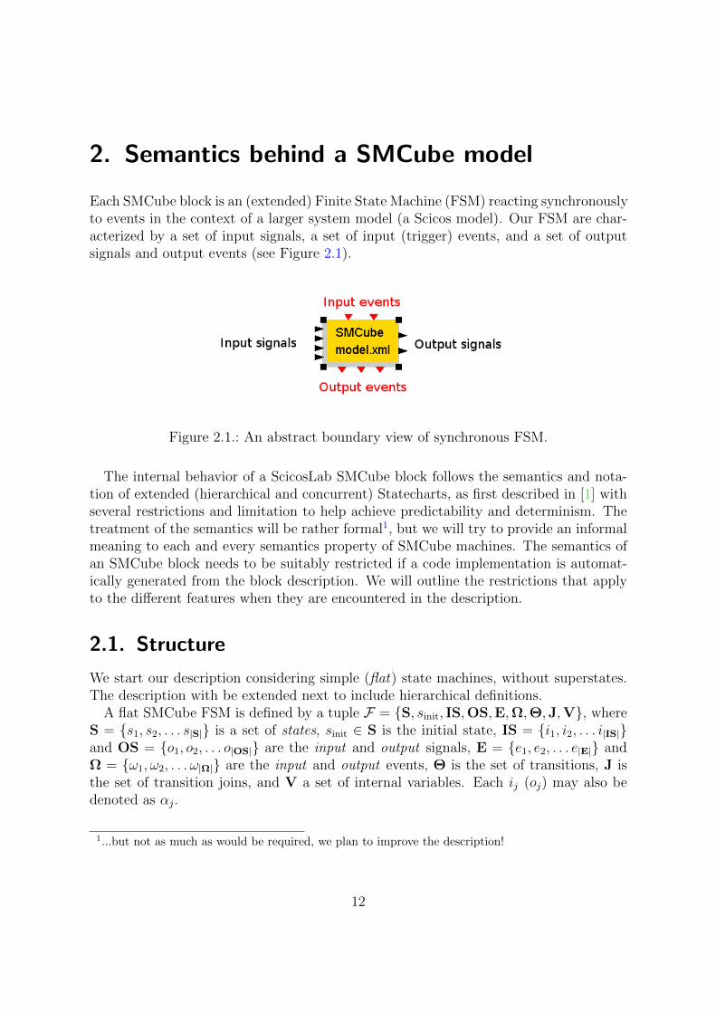
Each SMCube block is an (extended) Finite State Machine (FSM) reacting synchronouslyto events in the context of a larger system model (a Scicos model). Our FSM are char-acterized by a set of input signals, a set of input (trigger) events, and a set of outputsignals and output events (see Figure 2.1).
Figure 2.1.: An abstract boundary view of synchronous FSM.
The internal behavior of a ScicosLab SMCube block follows the semantics and nota-tion of extended (hierarchical and concurrent) Statecharts, as first described in [1] withseveral restrictions and limitation to help achieve predictability and determinism. Thetreatment of the semantics will be rather formal1, but we will try to provide an informalmeaning to each and every semantics property of SMCube machines. The semantics ofan SMCube block needs to be suitably restricted if a code implementation is automat-ically generated from the block description. We will outline the restrictions that applyto the different features when they are encountered in the description.
2.1. Structure
We start our description considering simple (flat) state machines, without superstates.The description with be extended next to include hierarchical definitions.
A flat SMCube FSM is defined by a tuple F = S, sinit, IS,OS,E,Ω,Θ,J,V, whereS = s1, s2, . . . s|S| is a set of states, sinit ∈ S is the initial state, IS = i1, i2, . . . i|IS|and OS = o1, o2, . . . o|OS| are the input and output signals, E = e1, e2, . . . e|E| andΩ = ω1, ω2, . . . ω|Ω| are the input and output events, Θ is the set of transitions, J isthe set of transition joins, and V a set of internal variables. Each ij (oj) may also bedenoted as αj.
1...but not as much as would be required, we plan to improve the description!
12

Chapter 2. Semantics behind a SMCube model
Each signal is a function defined on the (continuous- or discrete-) time domain, withvalues in a given range. The range of the admissible values matches the range of program-level data types. Currently, scalar and vector types derived from primitive types (butnot structured or user-defined types) are allowed for IS, OS and V. Each signal isidentified by a unique name and a progressive index (indexes are assigned independentlyto input and output signals).
However, if a code implementation is extracted from the SMCube model, each signalmust be a discrete time function, with value changes occurring at times that are multipleof a base period. In this case, the discrete time domain of each signal αj matches thesystem base period Tb. Signal values only change at multiples of its period, defined asTαj
= kαj· Tb, and are persistent between updates.
E is the set of input (activation or trigger) events. Each event ej is asserted (true)at some points in time and not active (or false) at all others. Informally, each eventoccurs at arbitrary times and it is an indication of a point in time when somethingoccurs within the execution environment of the SMCube model. Each event is identifiedby a name and an index. Events do not carry data. In models that are used for thegeneration of code, signals are bound to occur only at time instants belonging to atime base with period Tej multiple of Tb. At each time k · Tej the event may or maynot be present (alternatively, the machine may stutter). The periods of all signals andevents are therefore multiple of the base period. Similarly, Ω is the set of output events,representing points in time when the SMCube machine informs the model environmentof the occurrence of something of interest.
Θ is the set of transition rules. Each transition θj ∈ Θ consists of a tuple θj =src(θj), dst(θj), ε(θj), gj, aj, wj, pj, where src(θj) ∈ S ∪ J is the source state or join (seelater), dst(θj) ∈ S ∪ J is the destination state or join, ε(θj) is the trigger expression, gjis the guard condition (an expression with boolean value of the input and output signalsand internal variable values), aj is the action, wj = ωj,0, ωj,1, . . . ωj,n with ωj,k ∈ Ωis the set of generated output signals, and pj is the transition priority (the lower thenumber, the higher the priority). Priorities must be unique among all the transitionswith the same source state. The trigger expression ε(θj) is an AND-OR combinationof input signals ej ∈ E. The guard gj can be a boolean-valued expression obtained asa C language boolean-valued expression using the comparison operators and arithmeticoperators of the C language together with the values of the input signals and the internalvariables. The action aj is a sequence of action statements, in which each statement canbe
the assignment of a value to one of the internal variables.
the assignment of a value to one of the output signals
setting one of the output events
Each element of the set J = j1, j2, . . . j|J| is formally defined as a product ji =θini ×Θout
i , of an incoming transition θini and a set of outgoing transitions Θouti ⊆ Θ with
the following restrictions: the source of θini cannot be a join, and the destination of anyθ ∈ Θout
i cannot be a join.
13

Chapter 2. Semantics behind a SMCube model
Each state sj ∈ S is further characterized by a name and a set en(sj), ex(sj), wh(sj).en(sj) is the entry action for state sj. It is an action (see the description of the actionsassociated to transitions) executed whenever sj is the destination of an active transition.ex(sj) is the exit action, executed whenever sj is the source of an active transition.wh(sj) is the while action, executed whenever an input event is active, state sj is theactive state and no transition is taken.
Please note the following:
the FSM never reacts to events generated from within the state machine. Thespace of the input and output events is separated
Superstates and hierarchy
SMCube FSMs can be hierarchical. In this case, one of the machine states can be asuperstate of type AND (concurrent) or OR (alternative).
A superstate of type OR −j ∈ Λ retains all the structural characteristics of flatFSM states. As such, it can be used in an FSM model as any state sj and en-try, exit and while actions can be defined for it. However, a superstate −j also hasan internal structure, defined by applying recursively the definition of an FSM Γj =S, sinit, IS,OS,E,Ω,Θ,J,V. As such, an OR superstate has an internal set of states.Transitions can be defined with −j as the source or destination. There can be four typesof transitions with endpoints in −j . A transition from an external state (or an externaltransition join) into −j , a transition from −j to an external state (or join), a transitionfrom an internal state (or internal join) to −j and, finally, from −j to one of its internalstates or joins.
A superstate of type AND ±j ∈ Λ is defined as a set of concurrent superstates±j = Φ1,Φ2, ...,Φn. Each superstate ±j may be the source of destination of transitionsfrom external states or joins. Each concurrent (super)state ⊕j is characterized by apriority or execution order πj from 1 to n. A concurrent state may in turn be a simplestate, or a superstate of type OR or AND. In these two cases, it is internally definedby applying recursively the definition of an FSM Φj = S, sinit, IS,OS,E,Ω,Θ,J,V.Entry, exit and while actions can be defined for both ±j and ⊕j.
Concurrent superstates cannot be the source or destination of any transition to anyother external state.
2.2. Syntax
The SMCube syntax is graphical and is described in the following Figures:
Figure 2.2 shows an initial (pseudo)state.
Figure 2.3 shows a state with its entry, exit and while actions.The syntax for entry, exit and while actions is a subset of the ANSI C/C++
14

Chapter 2. Semantics behind a SMCube model
Figure 2.2.: An initial state of a SMCube State Machine.
Figure 2.3.: A State with its entry, exit and while actions.
language syntax:Entry, Exit, While: in the property window of the state, the accepted syntax is aset of ANSI C/C++ statements separated by semicolons ; .
Each statement may refer only to the following identifiers:
– input signal values with the syntax In(in signal name )
– output signal values with the syntax Out(out signal name )
– internal variable values with the syntax Var(var name )
The arithmetic operators, the bitwise operators and the compound assignmentoperators accepted by the C/C++ language of the C/C++ language are accepted.The C/C++ comments are not supported and must not be used.In the graphical view, the entry action is shown with the prefix En: , the exitaction with the prefix Ex: , the while action with the prefix Wh: .
Figure 2.4 shows a transition, the graphical notation of a transition is a directedlink (as indicated by the arrow) from the source state to the destination state.Please note that the priority appears at the foot (origin) of the transition link,the trigger event expression is shown together with the guard (appearing betweensquared parenthesis) in a string that is associated with the link and can be moved.A separate string shows the action.The syntax for events; conditions and actions is a subset of the C/C++ syntax:Events : in the property window of the transition, events are indicated with their
15
Chapter 2. Semantics behind a SMCube model
Figure 2.4.: A transition between two SMCube states.
Figure 2.5.: Superstates of type OR and AND
identifiers, if the transition is activated by multiple events, the event identifiers areseparated by the C OR operator ‖. In the graphical view, the events are shown inblue right before the transition condition.Condition (guard): in the property window of the transition, the condition isexpressed as a C language expression returning a binary value.
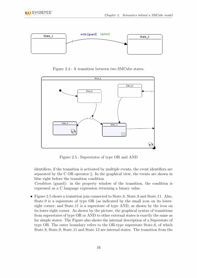
Figure 2.5 shows a transition join connected to State 8, State 9 and State 11. Also,State 9 is a superstate of type OR (as indicated by the small icon on its lower-right corner; and State 11 is a superstate of type AND, as shown by the icon onits lower-right corner. As shown by the picture, the graphical syntax of transitionsfrom superstates of type OR or AND to other external states is exactly the same asfor simple states. The Figure also shows the internal description of a Superstate oftype OR. The outer boundary refers to the OR-type superstate State 6, of whichState 8, State 9, State 11 and State 12 are internal states. The transition from the
16

Chapter 2. Semantics behind a SMCube model
Figure 2.6.: A superstate of type AND: internal view with its concurrent states in theirswimlanes.
boundary of State 6 to State 12 is an example of a transition from a superstate toone of its internal states. similarly, the transition from State 11 to the boundary isan example of a transition from an internal state to a superstate. These transitionsare defined using the same syntax as transitions from two regular (non hierarchical)states.
Figure 2.6 shows an example of the graphical syntax for superstates of type AND.The figure shown the internal structure of the AND superstate State 1. Its in-ternal concurrent states State 2, State 3 and State 4 are shown inside verticalswimlanes. The priority/execution order of the concurrent states is shown insidethe corresponding swimlane on the bottom-left corner. The swimlanes are only agraphical (notation) convenience and their only purpose it to force the placementof internal concurrent states in a way that clearly identifies them as concurrent(as opposed to the internal states of an OR-type superstate) and allows to identifytheir execution order.As shown in the picture, the internal concurrent states can be simple states (asState 2), superstates of type OR (State 3) or superstates of type AND (State 4).There is no internal transition from the boundary of State 1 to any internal con-current state (such transitions cannot be defined) and between any two internalconcurrent states.Entry, exit and while actions may be defined for AND superstates.
2.3. Behavior
The behavior of the SMCube is defined as follows. First, we define the concept of activestate sa(t). At time t = 0 the active state is the initial state sinit = sa(0). At any point
17

Chapter 2. Semantics behind a SMCube model
in time t in which at least one of the events is active (note: in synchronous FSMs like theSMCube FSM, there may be more than one event active at the same time) the machinehas one currently active state.
2.3.1. Transitions from simple states
When a set of events are active at time t, the transitions outgoing from the current stateare sorted by priority. Priorities are used to discriminate which transition should beperformed when two or more events arrive synchronously and two or more correspondingtransitions can be taken out of a state. The event expression associated to each transitionin priority order is computed. If the event expression evaluates to false, then the nexttransition in priority order is considered. When an event expression is true for a giventransition, the corresponding guard is evaluated. If the guard evaluates to false, thenthe next transition in priority order is considered. If also the guard evaluates to true,then the transition is active and is taken. Formally, if the active transition is θ∗, then itmust be:
(1) src(θ∗) = sa(t)
(2) ε(θ∗)(t) = TRUE
(3) g(θ∗)(t) = TRUE
p∗ = minpk such that (1), (2), (3) are true for θk
Please note that at any point in time there can be one and only one active transition(the one with minimum priority index) or none.
2.3.1.1. Action execution order
When θ∗ is taken, the following actions are executed in order:
The exit action of the state src(θ∗) (if defined).
the action a(θ∗) (if defined).
The entry action of the state dst(θ∗) (if defined).
Then, the new active state becomes dst(θ∗).If no transition is active at time t for the active state, then
The while action of the state sa(t) is executed (if defined).
The generated output values and output event are produced at time t meaning that thereaction takes place in zero logical time.
Please note that (for a simple transition defined as a loopback on an atomic state)if the destination state is the same as the source state, the exit and entry actions areexecuted and the while action is not.
18

Chapter 2. Semantics behind a SMCube model
Figure 2.7.: Example of simple transitions
2.3.1.2. Transition Joins
The behavior for transitions from a source state to a transition join is the following.Consider transition join ji = θini ×Θi, of an incoming transition θini and a set of n out-going transitions Θi = θouti,1 , θ
outi,2 , ..., θ
outi,n . The join is equivalent to n transitions, each
resulting from the product of θini with one of the outgoing transitions. Each memberof the set product θ∗i,j = θini × θouti,j is a transition with event ε(θ∗i,j) = ε(θini )
∧ε(θouti,j )
obtained by the AND composition of the two events; guard g(θ∗i,j) = g(θini )∧g(θouti,j )
resulting from the AND composition of the two guards and an action obtained by con-catenating the action of the incoming edge and the action of the outgoing edge. Thepriority of the composition is the priority of its outgoing edge.
2.3.1.3. Examples
The following are examples of transitions for a simple (flat) state machine.Figure 2.7 shows a simple diagram with three simple (atomic) states and transitions
from the initial state State 4 to State 3 and State 5. When the FSM is executed for thefirst time, State 4 becomes active and its entry action Out(out2)=0 is executed.
Now, assume State 4 is active when event Evt1 arrives. The outgoing transitionsfrom State 4 are examined in order of their priority. If the value of input in0 is 0,then the guard form the transition with priority 1 is true and the transition is active.
19
Chapter 2. Semantics behind a SMCube model
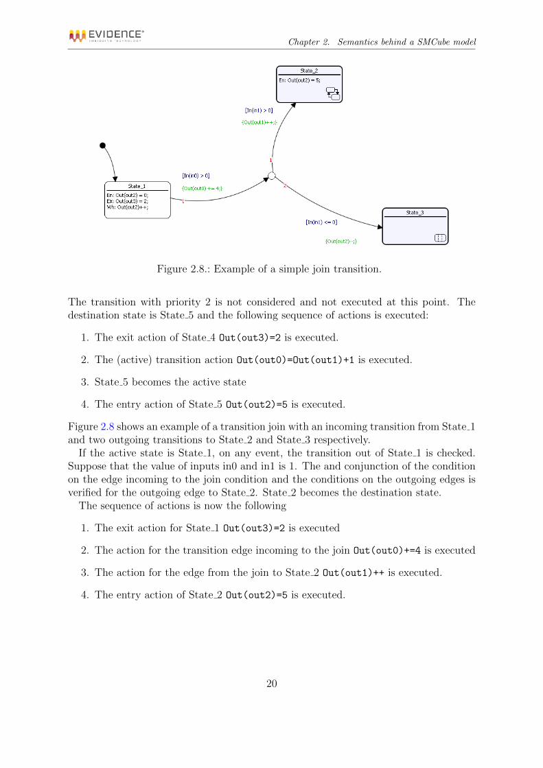
Figure 2.8.: Example of a simple join transition.
The transition with priority 2 is not considered and not executed at this point. Thedestination state is State 5 and the following sequence of actions is executed:
1. The exit action of State 4 Out(out3)=2 is executed.
2. The (active) transition action Out(out0)=Out(out1)+1 is executed.
3. State 5 becomes the active state
4. The entry action of State 5 Out(out2)=5 is executed.
Figure 2.8 shows an example of a transition join with an incoming transition from State 1and two outgoing transitions to State 2 and State 3 respectively.
If the active state is State 1, on any event, the transition out of State 1 is checked.Suppose that the value of inputs in0 and in1 is 1. The and conjunction of the conditionon the edge incoming to the join condition and the conditions on the outgoing edges isverified for the outgoing edge to State 2. State 2 becomes the destination state.
The sequence of actions is now the following
1. The exit action for State 1 Out(out3)=2 is executed
2. The action for the transition edge incoming to the join Out(out0)+=4 is executed
3. The action for the edge from the join to State 2 Out(out1)++ is executed.
4. The entry action of State 2 Out(out2)=5 is executed.
20

Chapter 2. Semantics behind a SMCube model
2.3.2. Superstates of OR type
When the model includes superstates, the behavior is the following. For superstates ofOR type, each time the superstate is entered as the result of a transition from an externalstate, the superstate becomes active and its entry action (is one is defined) is executed.Next, its initial transition from the initial (pseudo)state is executed and its destinationstate becomes the active state, the entry action of the active state is executed and thereaction terminates.
In case the state destination of the transition from the initial state is a superstate oftype OR, the behavior is executed recursively.
At any point in time there is one innermost state that is active an a hierarchy of(nested) superstates that are also considered as active.
2.3.2.1. Transitions from a superstate of type OR
Transitions from a superstate to one of its internal states and from one internal stateto the parent superstate have the following meaning. Each transition that has thesuperstate as source applies to all its internal states. Viceversa, any transition from aninternal state to the superstate is intended as a transition from the source state to theinitial (pseudo) state defined for the parent superstate. (the entry action of the parentsuperstate is not executed).
When an event arrives, the hierarchy of superstates of type OR is visited startingfrom the outermost superstate to the innermost (simple-type) active state. At eachpoint in the hierarchy, the transitions defined for the state are checked in order of theirpriority. If there is a transition defined for the corresponding event with a valid guard,the transition is the active transition for the current reaction, the destination state isannotated, and the recursive visit terminates. If there is no active transition, then thedestination state is the same as the current active state.
At this point, if there is an active transition, the hierarchy of active superstates oftype OR is visited until the state source of the active transition is reached and the exitactions are executed, starting from the outermost superstate, for all the superstatessuch that the current destination state is not contained in them. Next, the action ofthe active transition is executed. Then, the destination state becomes active. If it is asimple state, its entry action is executed. If it is a superstate of type OR or AND thesequence of actions that is executed when first entering the superstate is executed.
Finally, the hierarchy of superstates is visited one last time, from the outermost state,and the while actions are executed for all the superstates that are still active for the new(simple) active state.
If there is no active transition, then the hierarchy of active states is visited startingfrom the outermost OR-type superstate and the while actions defined for all of them areexecuted in order.
21

Chapter 2. Semantics behind a SMCube model
2.3.2.2. Example
The following example (Figure 2.9) show the behavior for some cases of interest withOR superstates. The figure shows in a single picture three levels of the hierarchy (thecorrespondence is highlighted by the red dashed lines).The outer level consists of the states State 3 and State 1 (superstate of type OR). Theinternal states for State 1 are State 4 (superstate of type OR) and State 5. In turn,State 4 contains State 8. Please note that the SMCube editor only allows to see andoperate on one level of the hierarchy at a time, in a separate window.Case 1If the active state is State 3, the event Evt0 becomes active and the guard conditionon the input signals [In(in0]>0 \&\& In(in1)>0] is true, then the transition out ofState 3 becomes active and the following steps are executed in order.
1. The action Out(out3)=0 is executed, updating the output signal out3 with thevalue 0.
2. The transition action Out(out2)=In(in0)+In(in1)is executed, updating the out-put signal out2 with the sum of the values for the input signals in0 and in1.
3. The superstate State 1 becomes active.
4. Its Entry action Out(out1)=0 is executed.
5. Its internal state is set to State 4 (pointed by the transition out of the initialpseudostate), which becomes active.
6. The entry action Out(out2)=0 for State 4 is executed. This action assigns a newvalue to out2, nullifying the effect of the second step in the sequence.
7. The internal state of State 4 is State 8, which becomes active.
8. The entry action for State 8 Out(out2)=0 is executed.
At the end of this sequence, there is only one simple state (State 8) active at the endof the hierarchy, and a set of active superstates tracing all levels up to the root level(State 1 →State 4).
Case 2Suppose now State 8 is active (and the hierarchy with State 1 and State 4 on top of it)and event Evt1 occurs, with the value of the input signal in0 at 1.
In this case, all the outgoing transitions for State 1, State 4 and then State 8 areexamined in order. None of them is active (the transition out of State 4 is tagged withEvt1 but the guard condition is false) and the destination state is the same as the currentstate.
The while actions of State 1, State 4 and State 8 are executed in order (Out(out1)++followed by Out(out2)++, finally followed by Out(out2)=in(in0)+1).Case 3
22

Chapter 2. Semantics behind a SMCube model
Figure 2.9.: An example with a hierarchy of superstates of type OR.
23

Chapter 2. Semantics behind a SMCube model
Now, suppose State 8 is active when event Evt1 arrives and the value of the inputsignal in0 is 0. In this case, the outgoing transitions from State 1 are checked, then,those from State 4. On State 4 the outgoing transition to State 5 becomes active andState 5 is the destination state. The following sequence of actions takes place
1. The exit action for State 4 Out(out3)=2 is executed.
2. The exit action for State 8 Out(out3)=1 is executed (nullifying the previous ac-tion).
3. The transition action for the transition out of State 4 Out(out0)=Out(out1)+1 isexecuted.
4. The entry action for State 2 Out(out2)=5 is executed.
5. The while action for State 1 Out(out1)++ is executed.
Case 4Finally, suppose State 5 is active when event Evt0 arrives and the value of both in0
and in1 is different from 0. In this case, the transition from the superstate State 1 toits internal state State 4 is the first active transition in the visited hierarchy. State 4 isthe destination state. The following sequence of actions takes place
1. The exit action for State 5 Out(out3)=4 is executed.
2. The transition action for the transition inside State 1 Out(out0)=In(in0)*In(in1)is executed.
3. The entry action for State 4 Out(out2)=0 is executed.
4. The entry action for State 8 Out(out2)=0 is executed.
5. The while action for State 1 Out(out1)++ is executed.
2.3.3. Superstates of AND type
For superstates of AND type, each time the superstate is entered as the result of atransition from an external state, the superstate becomes active and its entry action (isone is defined) is executed. Next, its internal concurrent states are evaluated in order,according to the order index in their swimlanes. In case the one of the concurrent statesis a superstate of type AND the behavior is executed recursively.
At any point in time there is one innermost state for each concurrent state that isactive, and possibly for each of them a hierarchy of (nested) superstates that are alsoactive (the superstates of AND type can be composed in a hierarchy of arbitrary depth).Formally, a superstate of type AND ±j has a set of concurrent (super)states ±j =Φ1,Φ2, ...,Φn. If at any point in time, the active state of each of its concurrent statesis sactivej,i ∈ ⊕j the active state of ±j is defined as the product sactivej,1 ×sactivej,2 × . . .×sactivej,n .
24
Chapter 2. Semantics behind a SMCube model
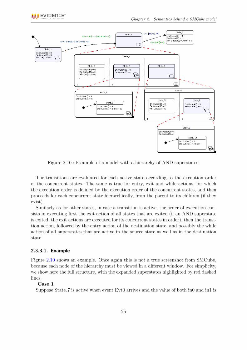
Figure 2.10.: Example of a model with a hierarchy of AND superstates.
The transitions are evaluated for each active state according to the execution orderof the concurrent states. The same is true for entry, exit and while actions, for whichthe execution order is defined by the execution order of the concurrent states, and thenproceeds for each concurrent state hierarchically, from the parent to its children (if theyexist).
Similarly as for other states, in case a transition is active, the order of execution con-sists in executing first the exit action of all states that are exited (if an AND superstateis exited, the exit actions are executed for its concurrent states in order), then the transi-tion action, followed by the entry action of the destination state, and possibly the whileaction of all superstates that are active in the source state as well as in the destinationstate.
2.3.3.1. Example
Figure 2.10 shows an example. Once again this is not a true screenshot from SMCube,because each node of the hierarchy must be viewed in a different window. For simplicity,we show here the full structure, with the expanded superstates highlighted by red dashedlines.
Case 1Suppose State 7 is active when event Evt0 arrives and the value of both in0 and in1 is
25

Chapter 2. Semantics behind a SMCube model
greater than 0. In this case, the transition from the superstate State 7 to the superstate(of AND type) State 1 is active. State 1 is the destination state. The following sequenceof actions takes place
1. The exit action for State 7 Out(out3)=0 is executed.
2. The transition action for the transition from State 7 to State 1 is executedOut(out2)=In(in0)+In(in1).
3. Superstate State 1 becomes active. Its internal superstates AND: State 2, State 3and State 4 are active. Their reactions are evaluated in the order of their priorityon the swimlanes.
4. The entry action for State 2 Out(out2)=0 is executed.
5. The entry action for State 3 Out(out1)=0 is executed.
6. The initial state for superstate State 3, State 9 is active and its entry actionOut(out2)=0 is executed.
7. Inside State 4, the internal superstates State 5 and State 6 are active. Their reac-tions are evaluated in the order of their priority on the swimlanes.
8. The entry action for State 5 Out(out1)=0 is executed.
9. The entry action for State 6 Out(out2)=5 is executed.
10. The initial state for superstate State 6, State 10 is active and its entry actionOut(out1)=0 is executed.
At the end of the reaction, the active states are (superstates in italic, shown in theevaluation order): State 1, State 2, State 3, State 9, State 4, State 5, State 6, State 10.
Case 2Suppose the active states are the same as at the end of the previous Case 1. Event Evt1becomes active and the guard condition on the input signals [In(in1)>0] is true, thenthe transition out of State 1 becomes active and State 8 becomes the destination state.The following actions are executed.
1. The exit action for State 1 is evaluated. Since State 1 is a superstate of type AND,this means evaluating the exit actions (in order) of State 2, State 3 and State 4.
2. The exit action for State 2 is Out(out3)=0.
3. The exit action for State 3 Out(out3)=4 is executed. since State 3 is an OR-typesuperstate, its internal exit actions are executed recursively.
4. The exit action for State 9, active within State 3 is executed: Out(out3)=In(in1)-1.
26

Chapter 2. Semantics behind a SMCube model
5. The exit action for State 4 is evaluated. Since State 4 is a superstate of type AND,this means evaluating the exit actions (in order) of State 5 and State 6.
6. The exit action for State 5 is Out(out1)=2.
7. The exit action for State 6 Out(out3)=4 is executed. since State 6 is an OR-typesuperstate, its internal exit actions are executed recursively.
8. The exit action for State 10, active within State 6 is executed: Out(out1)=In(in0).
9. The transition action for the transition from State 1 to State 8 is executed Out(out1)++.
10. State 8 becomes active. Its entry action Out(out2)=0 is executed.
27

3. Integration with ScicosLab
The E4Coder toolbox provides a customized block which can be used to integrate one ormore SMCube state machines inside a ScicosLab diagram. The block, named SMCube(see Figure 3.1), allows the simulation and code generation of a state machine with agiven number of inputs, and a given number of outputs. The block shows the statemachine xml file and the input and output signals names if defined (see further).
Figure 3.1.: An SMCube block with three inputs and three outputs.
The number of inputs and outputs, as well as the number of incoming and outgoingevents can be modified by acting on the SMCube data model. There can be more thanone SMCube block inside a ScicosLab diagram.
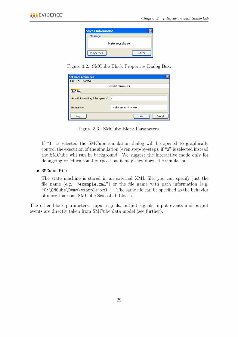
Double clicking on the SMCube Block opens the Property Dialog Box as shown inFigure 3.2. The window shows two possible options:
Properties which can be used to edit the parameters of the block (See Figure 3.3).
Editor which can be used to edit the diagram (see Chapter 4).
The block properties dialog box provides the following options:
Mode (1:interactive, 2:background)
This parameter controls the execution mode of the state machine at simulationtime.
28
Chapter 3. Integration with ScicosLab
Figure 3.2.: SMCube Block Properties Dialog Box.
Figure 3.3.: SMCube Block Parameters.
If “1” is selected the SMCube simulation dialog will be opened to graphicallycontrol the execution of the simulation (even step-by-step); if “2” is selected insteadthe SMCube will run in background. We suggest the interactive mode only fordebugging or educational purposes as it may slow down the simulation.
SMCube File
The state machine is stored in an external XML file; you can specify just thefile name (e.g. “example.xml”) or the file name with path information (e.g.“C:\SMCube\Demo\example.xml”) . The same file can be specified as the behaviorof more than one SMCube ScicosLab blocks.
The other block parameters: input signals, output signals, input events and outputevents are directly taken from SMCube data model (see further).
29
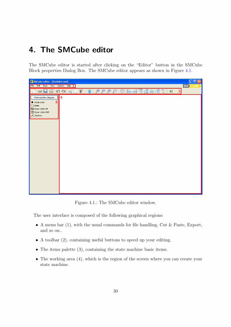
4. The SMCube editor
The SMCube editor is started after clicking on the “Editor” button in the SMCubeBlock properties Dialog Box. The SMCube editor appears as shown in Figure 4.1.
Figure 4.1.: The SMCube editor window.
The user interface is composed of the following graphical regions:
A menu bar (1), with the usual commands for file handling, Cut & Paste, Export,and so on..
A toolbar (2), containing useful buttons to speed up your editing.
The items palette (3), containing the state machine basic items.
The working area (4), which is the region of the screen where you can create yourstate machine.
30

Chapter 4. The SMCube editor
4.1. Drawing states
The items palette shown in part (3) of Figure 4.1 contains the following items:
The initial state;
A regular state;
An OR state;
An AND state;
A junction.
To put an item onto the working area (4), you need to drag the item from the palette tothe scene. After that, you can move the shapes by first selecting the item with a click,and then dragging it to the appropriate position.
For example, in Figure 4.2, the initial state, a regular state (named State 2), an ORstate (named State 3), an AND state (named State 4) and a junction state (the circlein the middle of the other states) have been dropped on the scene.
The objects can be moved by clicking on the object of interest than moving the mousein the new position and releasing the mouse. When the mouse cursor is over a movableobject the shape change into an “open hand pointer”.
You can also resize objects. The initial state can be resized by dragging the squarehandles at the edges of the object (see 4.2). The size of the black dot is controlled inthe global preferences (see Figure 4.13). The regular, OR and AND state objects canbe resized by dragging its corners (see Figure 4.3) while the junction cannot be resized.
The internal OR state can be resized as well by dragging its bottom left corner whilethe internal AND state cannot be resized.
Most of the common editing commands works as expected. For example, you canselect more than one item simply drawing a rubber band selection rectangle on theworking area and covering all the items you are interested in. Then you will be able tomove these items (dragging them using your mouse) or delete them (pressing the DELkey or pressing “Cancel” in the Edit Menu). Multiple items selection can be done alsoclicking on the various items while keeping the CTRL key pressed. Copy, Cut and Pasteworks as well.
4.2. Drawing transitions
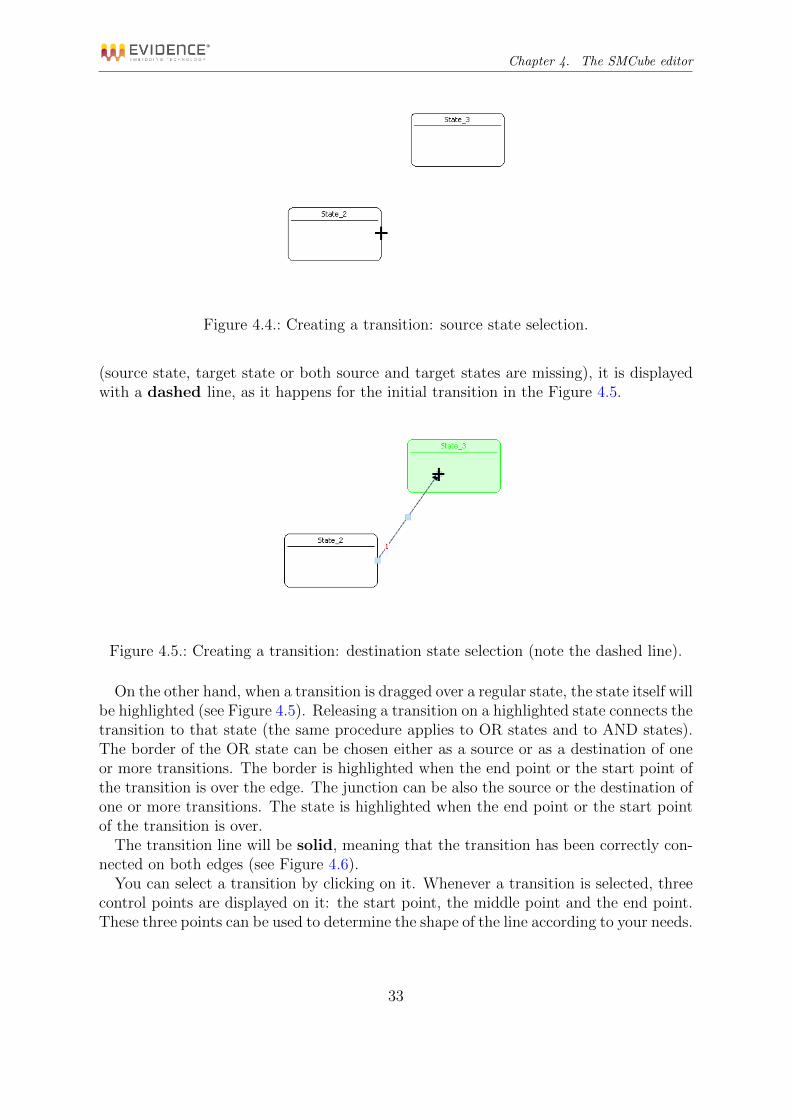
Creating a transition is extremely easy. Go with your mouse on the border of a regularstate, as shown in Figure 4.4. You will note that the cursor assumes a cross shape.
When the cursor is a cross, you can click the left button of your mouse and drag anew transition out of the state.
You can drop the transition arrow on the scene (not on a state). In that case, thetransition is not correctly connected. Whenever a transition is not properly connected
31

Chapter 4. The SMCube editor
Figure 4.2.: SMCube editor with states.
Figure 4.3.: How to resize a regular State.
32
Chapter 4. The SMCube editor
Figure 4.4.: Creating a transition: source state selection.
(source state, target state or both source and target states are missing), it is displayedwith a dashed line, as it happens for the initial transition in the Figure 4.5.
Figure 4.5.: Creating a transition: destination state selection (note the dashed line).
On the other hand, when a transition is dragged over a regular state, the state itself willbe highlighted (see Figure 4.5). Releasing a transition on a highlighted state connects thetransition to that state (the same procedure applies to OR states and to AND states).The border of the OR state can be chosen either as a source or as a destination of oneor more transitions. The border is highlighted when the end point or the start point ofthe transition is over the edge. The junction can be also the source or the destination ofone or more transitions. The state is highlighted when the end point or the start pointof the transition is over.
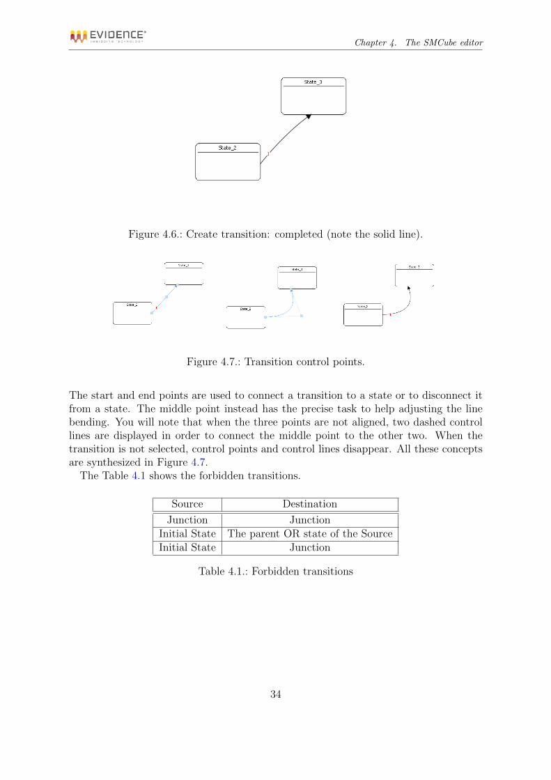
The transition line will be solid, meaning that the transition has been correctly con-nected on both edges (see Figure 4.6).
You can select a transition by clicking on it. Whenever a transition is selected, threecontrol points are displayed on it: the start point, the middle point and the end point.These three points can be used to determine the shape of the line according to your needs.
33
Chapter 4. The SMCube editor
Figure 4.6.: Create transition: completed (note the solid line).
Figure 4.7.: Transition control points.
The start and end points are used to connect a transition to a state or to disconnect itfrom a state. The middle point instead has the precise task to help adjusting the linebending. You will note that when the three points are not aligned, two dashed controllines are displayed in order to connect the middle point to the other two. When thetransition is not selected, control points and control lines disappear. All these conceptsare synthesized in Figure 4.7.
The Table 4.1 shows the forbidden transitions.
Source Destination
Junction JunctionInitial State The parent OR state of the SourceInitial State Junction
Table 4.1.: Forbidden transitions
34

Chapter 4. The SMCube editor
Figure 4.8.: OR superstate external representation
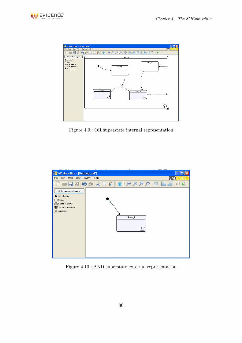
4.3. Navigate the state machine tree
The OR superstate and the AND superstate have an external and an internal represen-tation as shown in Figure 4.8, Figure 4.9, Figure 4.10 and Figure 4.11 respectively. Theinternal representation is shown when double clicking on the external representation;conversely, in order to go up from an internal representation of the superstate to the in-ternal representation that contains it the “Up Arrow” button, placed into the navigationtoolbar, should be pressed (see 4.5.6).
4.4. Preferences
Preferences control the parameters which apply to a specific object. SMCube has threekind of preferences.
Global Preferences Global preferences control the main settings of a SMCube diagram.
State Preferences State preferences are used to control the appearance and the behav-ior of a state, included entry, exit, and while actions.
Transition Preferences Transition preferences are used to control the transition prior-ity, as well as the transition guards and actions.
4.4.1. Global preferences
Global Preferences are used to specify attributes that apply globally to the entire Statemachine.
35
Chapter 4. The SMCube editor
Figure 4.9.: OR superstate internal representation
Figure 4.10.: AND superstate external representation
36

Chapter 4. The SMCube editor
Figure 4.11.: AND superstate internal representation
To change the Global Preferences, you can access the Preferences dialog going toOptions Preferences. . . , or you can right click on the scene selecting “Preferences. . . ”from the context menu.
The Global Preferences dialog is composed of three tabs.
State Machine Tab The first tab allows you to change the state machine name (seeFigure 4.12).
States Tab The second tab allows you to change the default parameters used when newstates are created (see Figure 4.13).
Transitions Tab The third tab allows you to change the default parameters used whennew transitions are created (see Figure 4.14).
4.4.2. State preferences
The State Preferences Dialog Box displays the basic information about a state. To editthe parameters of a specific state, you can right click on the state itself and select the“Edit preferences” item, in order to access the State preferences Dialog Box (see Figure4.15).
This Dialog Box allows you to change the state name, width, height, font family andfont size. Furthermore it is possible to set an entry action, an exit action and a whileaction for the state: these are C-like expressions, written using the data model (seeSection 4.6). The type of the state can be changed too (Warning: if the previoustype is one of the super state, AND or OR, the sub-tree structure inside thestate will be lost).
Note that a state can be resized also by selecting it and dragging one of its corners,as shown in Figure 4.3.
37

Chapter 4. The SMCube editor
Figure 4.12.: Global preferences: State Machine.
Figure 4.13.: Global preferences: States.
38

Chapter 4. The SMCube editor
Figure 4.14.: Global preferences: transitions.
Figure 4.15.: State preferences Dialog Box.
39

Chapter 4. The SMCube editor
Figure 4.16.: Transition preferences Dialog Box.
4.4.3. Transition preferences
To edit the parameters of a specific transition, you can right click on the transitionitself and select the “Edit preferences” item, in order to access the transition preferencesdialog.
The Dialog Box shown in Figure 4.16 allows you to change the transition events, guardand action, which are expressed as C-like expressions, written using the data model (seeSection 4.6). If the Events field is not empty the transition is taken if and only if itsboolean expression evaluates to true and, if specified, the guard evaluates to true too.
The “Visible” check box enables or disables the displaying of text items (event, guardand action). It is also possible to change the font family and the font size for such textitems. When visible, you can move these elements by dragging them in the appropriatepositions. If you move the transition, and you need to readjust the position of the threetext boxes, you can make these boxes invisible and then visible again, and they will bepositioned near the transition line.
Finally, you can change the transition priority. Higher priority values denote a lowerpriority in transition execution. Changing a priority implicitly reassigns all priorities ofthe transitions going out from the same regular state. Please always remember that thepriority number is relative to the state where the transition starts (in other words, whenlooking at Figure 2.4, priorities are related to State 1 and are not related to State 2).
40
Chapter 4. The SMCube editor
4.5. Toolbar
As shown in Figure 4.1, the SMCube editor has a toolbar with several buttons allowingyou to perform different operations.
4.5.1. File
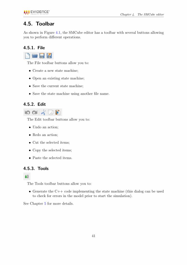
The File toolbar buttons allow you to:
Create a new state machine;
Open an existing state machine;
Save the current state machine;
Save the state machine using another file name.
4.5.2. Edit
The Edit toolbar buttons allow you to:
Undo an action;
Redo an action;
Cut the selected items;
Copy the selected items;
Paste the selected items.
4.5.3. Tools
The Tools toolbar buttons allow you to:
Generate the C++ code implementing the state machine (this dialog can be usedto check for errors in the model prior to start the simulation).
See Chapter 5 for more details.
41
Chapter 4. The SMCube editor
4.5.4. Zoom
The Zoom toolbar buttons allow you to:
Increase the zoom level;
Decrease the zoom level;
Restore the zoom level to 1:1;
Fit all the items in the view.
4.5.5. Align
The Align toolbar buttons allow you to align the selected states in various way. Theleftmost button states whether the alignment is done with respect to the page or not,while the other buttons allow you to align to the left, the right, the top, the bottom,vertically and horizontally.
The last button is used to reposition the action and guard texts close to the transitionthey belong to. This action applies only to the selected transitions.
4.5.6. Navigation toolbar
The “up arrow” button allows you to navigate the state machine tree as described in4.3.
4.6. Data Model
SMCube allows you to define a Data Model, which is the list of variables used by theState Machine, with their types. The idea is that you can first define the Data Model,and afterward use the variables you defined in Actions, Guards, and so on, to controlthe behavior of the state machine.
4.6.1. Types of the Data Model
The current version of SMCube supports the types listed in Table 4.2. The table showsthe correspondence between the various types used in these contexts:
SMCube This is the type specification used in the State Machine Data Model.
42

Chapter 4. The SMCube editor
ScicosLab This is the type of the input/output of a SMCube block.
Simulation This is the type used when generating the C++ simulation engine.
Target This is the type used when generating code for an embedded target.
SMCube ScicosLab Simulation Target
REAL real (type 1) double double
INT32 int32 (type 3) int32 t int32 t
INT16 int16 (type 4) int16 t int16 t
INT8 int8 (type 5) int8 t int8 t
UINT32 uint32 (type 6) uint32 t uint32 t
UINT16 uint16 (type 7) uint16 t uint16 t
UINT8 uint8 (type 8) uint8 t uint8 t
Table 4.2.: Input/Output types mapping.
Finally, please note that:
Some embedded architectures could have restrictions due to the need of an efficientimplementation. A common restriction is the fact that double types may bemapped to 32-Bit single precision floating points.
4.6.2. Definition of the Data Model
Everything is done using a simple Dialog Box, which is accessible going to Options Data Model.
The Data Model Dialog Box is composed of five tabs:
Input Tab The first tab (see Figure 4.17) allows you to set input variables, specifyinga mnemonic name (optional), the type and the size.
43

Chapter 4. The SMCube editor
Figure 4.17.: Data Model: input data definition.
Output Tab The second tab is similar to the first, but is for output variables (see Figure4.18).
Figure 4.18.: Data Model: output definition.
Input Events The third tab allows you to define the input events (see Figure 4.19). Forthese variables only the name can be specified (actually the name is mandatory,see Section 4.6.3).
44

Chapter 4. The SMCube editor
Figure 4.19.: Data Model: input events.
Output Events The fourth tab is similar to the previous one and is used to define theoutput events (see Figure 4.20). For these variables, only the name (optional) canbe specified.
Figure 4.20.: Data Model: output events.
Local Variables Finally the fifth tab allows you to define local variables similar to inputand output definition (see Figure 4.21).
45

Chapter 4. The SMCube editor
Figure 4.21.: Data Model: local variables.
4.6.3. Usage of the Data Model
Once the variables have been defined in the Data Model Dialog Box, you can use thesevariables in expressions. To allow the Code Generator to properly parse the expressionsused in the guards, the expressions have to follow a specific formalism.
In particular, the following notation must be used:
Input data If you refer to scalars, you can use In(name) or In(index), or, if you refer tovectors, In(name)(index2) or In(index)(index2). index is the number shows inFigure 4.17, and index2 is the array element index (for vector signals). The inputcan be used everywhere except for the events field in the transition preferences.
Output data If you refer to scalars, you can use Out(name) or Out(index), or, if yourefer to vectors, Out(name)(index2) or Out(index)(index2). index is the num-ber shows in Figure 4.18, and index2 is the array element index (for vector signals).The output can be used everywhere except for the events field in the transitionpreferences.
Input events name1. For this kind of variables you can only check if they are activeor not the same way you do for boolean variables using a C-like notation: name
means “if the input event called name is active” while !name means “if the inputevent called name is not active”. The input events must only be used in the eventsfield of the transition preferences.
Output events Event(name) or Event(index), where index is the number shown in thefirst column of Figure 4.20. The C-like expression Event(evtout); means: “activate
1Not the index. This is why the name of the input event is mandatory in Figure 4.19.
46

Chapter 4. The SMCube editor
the output event port evtout”. The output events apply to actions (entry, exit andwhile for states and action for transitions).
Local Variables If you refer to scalars, you can use Var(name) or Var(index), orVar(name)(index2) or Var(index)(index2) if you refer to vectors. index is thenumber shows in Figure 4.21, and index2 is the array element index (for vectorvariables). The local variables can be specified everywhere except for the eventsfield in the transition preferences.
The notation InPort, OutPort and LocVar are obsolete (but still supported for com-patibility with older versions of SMCube).
The following reserved keywords (case sensitive) must not be used for name(s):InPort, OutPort, LocVar, In, Out, Var and Event.WARNING: the code generator for the embedded targets only support one input eventand zero output events; in other words, if you plan to generate code for an embeddeddevice do NOT use events inside your state machine.
4.6.4. Examples
This Section lists a set of correct and wrong actions, guards, and event expressions.Due to the fact that SMCube does not yet interpret those strings (see Section 5.1),
not all the errors can be caught by the tool, and only the execution of the code may sayif the code is correct.
The following examples suppose a Data Model which is made of a output vari-able myoutput, an input variable myinput, a local variable mylocvar, an input eventmyevinput, and an output event myevoutput.
4.6.4.1. Examples of actions
In general, actions are arbitrary C statements separated by a semi-colon. These arevalid actions:
Out(myoutput)=0;
Out(myoutput)++;
Out(myoutput) = In(myinput) + Var(mylocvar);
Var(mylocvar) += In(myinput) + Out(myoutput);
Var(mylocvar) += 1; Out(myoutput) = 0;
Events(myevoutput);
These are wrong actions:
out(myoutput)=0;
reason: the o is underscore.
47

Chapter 4. The SMCube editor
Out(myoutput)==0;
reason: there is no collateral effect in the statement. Use = and not ==;
Out(myoutput)=0
reason: missing semicolon at the end of the action;
In(myinput) = Out(myoutput);
reason: you cannot assign a value to an input port;
myfunc(Out(myoutput));
reason: you cannot call functions inside an action;
Events(myevoutput)=1;
reason: you cannot assign a value to an output event;
myevinput
reason: this is an input event not a real statement;
Events(myevinput);
reason: you can generate only output events.
4.6.4.2. Examples of guards
In general, guards are a single C expression. These are valid guards:
Out(myoutput)==0
Out(myoutput)==0 && In(myinput)!=2
These are wrong guards:
Out(myoutput)=0
reason: this always evaluate to false, as this is an assignment;
Out(myoutput)==0;
reason: no semicolon at the end of a guard.
4.6.4.3. Examples of events
In general, guards are a single C expression. These are valid event expressions:
myevinput
!myevinput
These are wrong event expressions:
48

Chapter 4. The SMCube editor
Out(myoutput)
reason: this is an output port and not an event;
Out(myoutput)=0;
reason: no expressions involving output ports, input ports, local variables, andoutput events;
myevinput=1;
reason: you cannot assign a value to an input event. only test it;
myevinput==1;
reason: event inputs are not numbers;
myevoutput
reason: this is an output event which can only be used inside one action.
49

5. Simulation of a SMCube model
SMCube integrates nicely with ScicosLab, providing two ways of simulating a StateMachine:
Interactive Mode In this mode, the SMCube editor shows a read-only zoomable view,that shows the evolution of the state machine, with highlighting of the currentmode, step-by-step execution, display of the events received by the simulator fromthe ScicosLab diagram. This mode is very useful for debugging a state machine,as well as for showing the run-time behavior of a diagram (see Section 5.2).
Batch Mode in this mode, no graphical output is displayed. All computation is donesilently, at maximum speed. This mode is useful when the state machine is con-sidered correct1, and there is a need for running batch simulations.
The connection between the ScicosLab simulation is done in the following steps:
1. Error Checking. The State Machine is checked to see if all requirements for codegeneration have been met.
2. Code Generation. The State Machine is generated as C++ code. A library isgenerated and automatically linked to the application.
3. Simulation. The State Machine is carried out when activated by the ScicosLabsimulation engine.
5.1. Error Checking and Code Generation
Error Checking and Code Generation are triggered in two ways:
On user request, when the user clicks on the “Generate Code” button in the ToolsMenu or in the Tools Toolbar (see Section 4.5.3).
Automatically, for each SMCube state machine contained in a ScicosLab diagram,when the ScicosLab simulation starts.
Since error reporting at ScicosLab simulation time is limited, we suggest to always verifythat a state machine generates correctly before starting a ScicosLab simulation.
Error Checking and Code Generation are strictly related. In fact, SMCube does notimplement internally an expression interpreter for guards and actions. Instead, SMCube
1That is, the state machine must pass the Error Checking and Code Generation as described in Section5.1.
50

Chapter 5. Simulation of a SMCube model
Figure 5.1.: Error checking before code generation.
simply generates a C++ structure containing an implementation of the state machine,which is compiled and then linked to verify that the actions and the guards are correctlyspecified.
Before generating the C++ structure, SMCube checks the following:
all states and transitions must be correctly connected (no dashed transitions!);
a proper data model exists.
If something goes wrong, a dialog is displayed with a list of errors. Moreover, if anerror involves a graphical element this element is highlighted in red when the errorentry is selected from the list (see Figure 5.1); if the element is not visible the externalrepresentation of the superstate containing the hidden item is highlighted instead (seeFigure 5.2).
Once the first consistency check has passed, you are ready to generate the code foryour state machine (see Figure 5.3). You just have to click on the “Generate” button,to see if there are any problems in compiling the library.
Once the state machine builds correctly, the system creates a DLL which is thenloaded. At this point the system is ready to simulate the state machine as described inSection 5.2.
The Code Generation dialog allows you to select the compiler used for the simulation;pressing the button “Select Compiler” the dialog shows in Figure 5.4 is displayed. The
51

Chapter 5. Simulation of a SMCube model
Figure 5.2.: Error checking before code generation with hidden element.
Figure 5.3.: Code generation of the State Machine before starting the simulation.
52

Chapter 5. Simulation of a SMCube model
Figure 5.4.: Simulation compiler selection
application tries to automatically detect the supported compilers installed in the systemand shows them for selection. If no compilers are found, it is still possible to select onemanually using the custom selection2.
5.2. State Machine Simulation
SMCube State Machines can be simulated by inserting an SMCube block inside a Sci-cosLab diagram, and then running a ScicosLab simulation. The simulation work flow isas follows:
When a ScicosLab simulation starts, the “init” part of each SMCube block createsan instance of the SMCube executable. That instance is run in “simulation mode”.The state machine is also silently compiled and loaded (as described in Section 5.1).
If no problems are found during compilation, SMCube creates an Inter-Process-Communication (IPC) channel with the ScicosLab executable for data exchangewith the ScicosLab simulator.
Every time the State Machine is triggered, data will be exchanged between Sci-cosLab and SMCube.
When the interactive mode is selected, SMCube opens the Simulation Dialog Box asshown in Figure 5.5.
The dialog is mainly composed of the following graphical regions:
2Usually you do not need to select the compiler if the installation of the E4Coder toolbox has beensuccessfully completed
53

Chapter 5. Simulation of a SMCube model
Figure 5.5.: Simulation Dialog Box.
Control buttons area (1) This area contains, from left to right, the play button, thestep button, the pause button and the up button. The first three buttons are usedto control the simulation state machine (see below) while the last button is usedto navigate the state machine tree as described in 4.3.
State Machine view area (2) This is a read-only zoomable view that shows the evolu-tion of the state machine. Please note that the current state and the last transitiontaken are highlighted. The state machine can be navigated as detailed in 4.3.
Debug area (3) This area shows a list of items; each item corresponds to an eventprocessed by the SMCube simulator. Each item can be enlarged to show its inputs,outputs, local variables and current state. The last event is always placed at theend of the list and the area is automatically scrolled to the bottom if the Go tolast event checkbox is checked.
Details area (4) This area shows a concise representation of the event currently selectedin the Debug area.
The simulation engine of SMCube can be described using a state machine, which isshown in Figure 5.6. The idea is that the events are evaluated continuously as they
54

Chapter 5. Simulation of a SMCube model
Figure 5.6.: The state machine of the SMCube simulation engine.
arrive in the PLAY STATE status. When in the STEP STATE, events are evaluatedone by one when the step button is clicked (allowing you to execute a step by stepsimulation).
55
6. Code Generation of a SMCube model
SMCube supports C-language code generation for embedded targets.In other words, it is possible to generate C code for an embedded target supported
by the E4Coder toolbox. The build process implemented in the E4Coder toolbox auto-matically calls the SMCube code generator to generate, starting from an SMCube XMLfile, an equivalent implementation in C Language, which can be then executed on thetarget as all the other blocks which are part of the toolbox. Furthermore, the SMCubecode generator is able to recognize “flat” state machine in order to optimize the codegenerated for straightforward models.
The limitations of the code generator are the following:
No support for more than one input event;
No support for generation of output events.
The E4Coder code generator will refuse to generate diagrams containing blocks notcompliant with the above limitations.
56

7. Examples
This Chapter shortly describes a few simple examples that can be used to demonstratethe features of SMCube1. All examples are distributed as part of the E4Coder toolbox,and consist of a ScicosLab diagram including one or more state machines, together withthe XML files implementing them.
All examples support both simulation from ScicosLab and Code Generation for anembedded target. The embedded target supported by these examples is the FLEX DemoBoard [4], which is simulated using the FLEX Demo Board Simulator block, describedin [3].
This document includes the description of three examples: a Tank (Section 7.1),a Digital Clock (Section 7.2) and a hierarchical version of the Digital Clock example(Section 7.3).
7.1. Tank example
This demo contains a simple state machine which simulates a tank with its fill level.The demo uses the Flex Demo Board Simulator to fill/empty the tank and to displaycurrent information about its status. More in details, the button B1 is used to fill thetank while the button B2 is used to empty it; each click changes the tank level by oneunit. The current tank level cannot be less than 0 and greater than 80. The LCD showsnumerically the status of the tank. Furthermore, the level is shown graphically by theLEDs according to the Table 7.1 (The LEDs are numbered in increasing order from thetop to the bottom). Figure 7.1 shows a screenshot of the simulator with a fill level of 45(corresponding to the first 5 LEDs on).
7.2. Digital clock example
This demo implements a digital clock state machine similar to the one presented in theoriginal paper from Harel [1]. This example uses the LCD and the buttons of the Flexdemo board simulator described in Section ??.
The digital clock runs in three modes: Time, Stopwatch and Alarm. B1 is used toswitch between these three modes.
1The examples shown in 7.1 and 7.2 have been produced with the version 1.0 of SMCube (the “flatversion”) so that they do not use super states and junctions. Furthermore, they refer the data modelwith the obsolete notation (OutPort, InPort and LocVar) and some conversion blocks are presentdue to limited types support of that version (just INT32 and REAL types).
57

Chapter 7. Examples
RANGE LED0 LED1 LED2 LED3 LED4 LED5 LED6 LED7
1-10 ON OFF OFF OFF OFF OFF OFF OFF11-20 ON ON OFF OFF OFF OFF OFF OFF21-30 ON ON ON OFF OFF OFF OFF OFF31-40 ON ON ON ON OFF OFF OFF OFF41-50 ON ON ON ON ON OFF OFF OFF51-60 ON ON ON ON ON ON OFF OFF61-70 ON ON ON ON ON ON ON OFF71-80 ON ON ON ON ON ON ON ON
Table 7.1.: Tank example: LEDs status depending on the Tank fill level.
Figure 7.1.: Tank example.
in Time mode (see Figure 7.2), the LCD shows the current time; time always startsfrom 00:00:00. The current time can be changed using B2 as described in Table7.2.
in Stopwatch mode (see Figure 7.3) the LCD shows the time counter (in a min-utes:seconds:milliseconds format) while the buttons are used to start, stop andclear it (see Table 7.3).
in Alarm mode (see Figure 7.4) an alarm clock can be set using the buttons (seeTable 7.4) while showing the alarm time on the LCD. When the alarm clock isringing you can stop it by pressing B2, B3, or B42.
2Actually, the alarm will ring only on the target because the Buzzer is not implemented yet in theFLEX Demo Board Simulator.
58

Chapter 7. Examples
Figure 7.2.: Digital Clock example: Time mode.
Mode B2 B3 B4
Show Time switch to Change Hours - -Change Hours switch to Change Minutes Increase Decrease
Change Minutes switch to Change Seconds Increase DecreaseChange Seconds switch to Show Time Increase Decrease
Table 7.2.: Digital clock example: adjusting time while in Time mode.
The ScicosLab model used for this example contains a superblock which is shown inFigure 7.5. The superblock contains four state machines:
Mode Selector : used to switch between the three modes explained above.
Time (inside the Time super block in Figure 7.5): used to manage the Timemode.
Stopwatch (inside the Stopwatch super block in Figure 7.5): used to manage theStopwatch mode.
Alarm (inside the Alarm super block in Figure 7.5): used to manage the Alarmmode.
We will now describe in detail the content of the Mode Selector state machine indetails, as it is relatively simple and easy to understand. The Mode Selector statemachine is the one highlighted in red in Figure 7.5.
The Mode Selector state machine takes one input, the B1 button of the Flex DemoBoard, and gives one integer output representing the current mode (0 for Time mode,1 for Stopwatch mode and 2 for Alarm mode). Figures 7.6 and 7.7 shows the data
59

Chapter 7. Examples
Figure 7.3.: Digital Clock example: Stopwatch mode.
Mode B2 B3 B4
Stopwatch Start Stop Clear
Table 7.3.: Digital clock example: Stopwatch mode.
model; only the input and the output are set while the local variables and events doesnot contain any data. Even though the block has one event input, as shown in theScicosLab model, we are not interested in testing its status because the state machine istriggered only by one event which is just the timed event given by the ScicosLab clock.
When button B1 is not pressed, the input to the state machine is set to 0, and thestate machine does not evolve (that is, there are no transitions depending on the value0 of the input, and there are no while actions in the states that may change the statemachine output or internal state).
Every time the button is clicked the input value to the state machine changes to 1. Atransition is triggered, and the current mode changes as explained above; the output ismodified accordingly to track the change of the internal state.
To show the state machine, you need to double click on the SMCube Scicoslab block,and choose “Editor” (see Figure 3.2; also refer to Chapter 3). SMCube opens as shownin Figure 7.8. The state machine is composed of three states (TIME, STOPWATCH andALARM) and three transitions (other than the mandatory initial transition).
Each state executes one statement in the entry action setting the output to the integerrepresenting its code (for example, the state TIME has the entry action OutPort(code)=0;).Indeed, the data model defines one output named code and it is modified using the no-tation explained in Section 4.6.3.
Transitions are triggered every time the input named switch mode is different from 0
i.e., the button B1 is pressed (for example, the transition going out of the state TIME is
60

Chapter 7. Examples
Figure 7.4.: Digital Clock example: Alarm mode.
Mode B2 B3 B4
Set Alarm switch to Change Hours Enable DisableChange Hours switch to Change Minutes Increase Decrease
Change Minutes switch to Set Alarm Increase Decrease
Table 7.4.: Digital clock example: Alarm mode.
InPort(switch mode)3). As already stated above, the input is referred using the nota-tion shown in Section 4.6.3. Hence, when button B1 is pressed, the following happens:
Button B1 changes value from 0 to 1;
The transition is triggered because the guard becomes true;
There is no exit action to be executed (if there was, it would have been executed);
The entry action of the destination state is executed. As a result, the output isset to the actual code value
This execution order respect what explained in Chapter 2, where we said that the actionsexecution order is: exit action of the source state; transition action; entry action of thetarget state.
Please also note that in this simple state machine the exit and while actions are emptyso that no statements are carried out when the source state is exited or no transitionsare triggered when the state machine is in a given state. Furthermore, no actions areassociated to the transitions, hence, no statements are exploited between the exit fromthe source state and the entry into the target state.
3which is equivalent to InPort(switch mode)!=0
61

Chapter 7. Examples
Figure 7.5.: Digital Clock example: the ScicosLab superblock containing the model.
Figure 7.6.: Digital Clock example: the Data Model input part.
7.3. Hierarchical digital clock example
In this section we show a “hierarchical” version of the example seen in 7.2. The exam-ple behaves the same as the “flat” version but we take advantage from the hierarchyimprovement. The main superblock of the ScicosLab model is shown in Figure 7.9.
This model has just one SMCube block instead of four as the flat version has; thestate machine is shown in Figure 7.10 (the external and the internal representation). Asyou can see, the “root” node is an AND superstate which is composed of three parallelstates: MODE, STOPWATCH and ALARM.
The MODE superstate is responsible for the mode selection; it is composed of threestates one for each mode: TIME MODE, STOPWATCH MODE and ALARM MODE;the output of the state machine is changed to display the information relevant for thecurrent mode. In this state there is an example of use of the junction. When the currentstate is STOPWATCH MODE the output transition, with the junction as destination,is taken if the mode button is pressed; then, if the alarm is set (Var(alarm set) variabletest) the left transition is taken otherwise the right transition is taken going into the
62
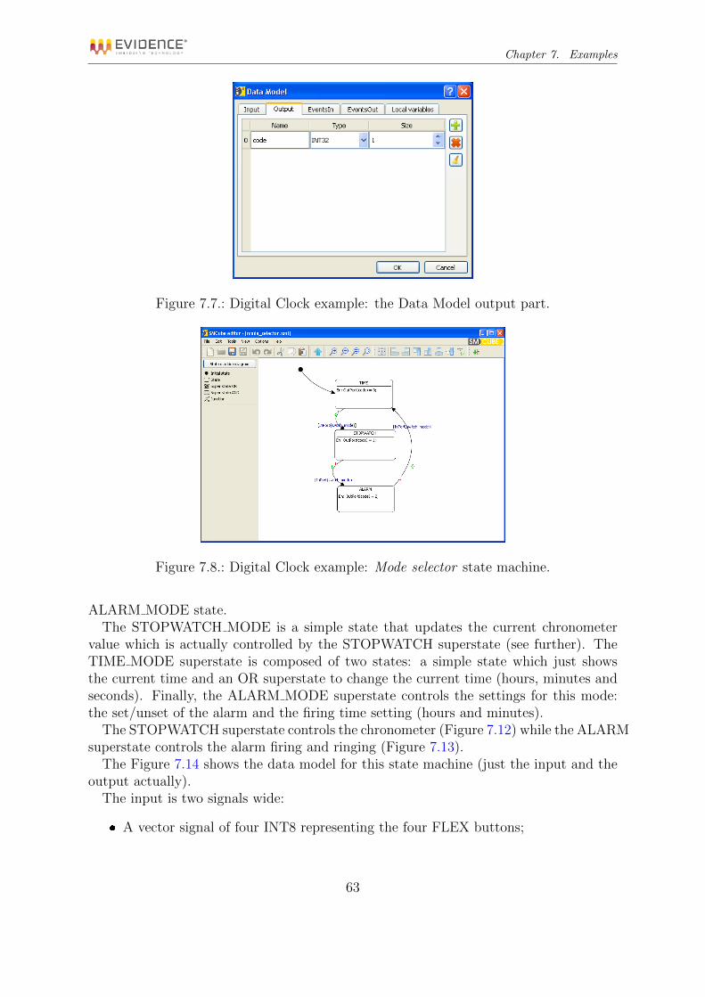
Chapter 7. Examples
Figure 7.7.: Digital Clock example: the Data Model output part.
Figure 7.8.: Digital Clock example: Mode selector state machine.
ALARM MODE state.The STOPWATCH MODE is a simple state that updates the current chronometer
value which is actually controlled by the STOPWATCH superstate (see further). TheTIME MODE superstate is composed of two states: a simple state which just showsthe current time and an OR superstate to change the current time (hours, minutes andseconds). Finally, the ALARM MODE superstate controls the settings for this mode:the set/unset of the alarm and the firing time setting (hours and minutes).
The STOPWATCH superstate controls the chronometer (Figure 7.12) while the ALARMsuperstate controls the alarm firing and ringing (Figure 7.13).
The Figure 7.14 shows the data model for this state machine (just the input and theoutput actually).
The input is two signals wide:
A vector signal of four INT8 representing the four FLEX buttons;
63

Chapter 7. Examples
Figure 7.9.: Hierarchical digital clock example
Figure 7.10.: Hierarchical digital clock: CLOCK superstate
64

Chapter 7. Examples
Figure 7.11.: Hierarchical digital clock: MODE superstate
Figure 7.12.: Hierarchical digital clock: STOPWATCH superstate
65
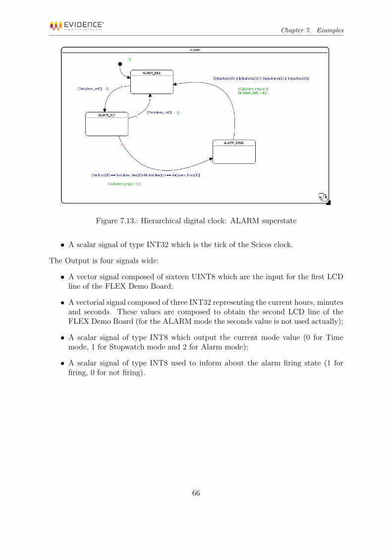
Chapter 7. Examples
Figure 7.13.: Hierarchical digital clock: ALARM superstate
A scalar signal of type INT32 which is the tick of the Scicos clock.
The Output is four signals wide:
A vector signal composed of sixteen UINT8 which are the input for the first LCDline of the FLEX Demo Board;
A vectorial signal composed of three INT32 representing the current hours, minutesand seconds. These values are composed to obtain the second LCD line of theFLEX Demo Board (for the ALARM mode the seconds value is not used actually);
A scalar signal of type INT8 which output the current mode value (0 for Timemode, 1 for Stopwatch mode and 2 for Alarm mode);
A scalar signal of type INT8 used to inform about the alarm firing state (1 forfiring, 0 for not firing).
66

Chapter 7. Examples
Figure 7.14.: Hierarchical digital clock: the data model
67

A. QT Libraries Licensing
SMCube is written using the Qt Libraries, which are dynamically linked to the ex-ecutable. The Qt GUI Toolkit is Copyright (C) 2011 Nokia Corporation and/or itssubsidiary(-ies), and the following license applies.
The GNU Lesser General Public License (Version 2.1)
GNU LESSER GENERAL PUBLIC LICENSEVersion 2.1, February 1999
Copyright (C) 1991, 1999 Free Software Foundation, Inc.51 Franklin Street, Fifth Floor, Boston, MA 02110-1301 USAEveryone is permitted to copy and distribute verbatim copies of this license document, but
changing it is not allowed.
[This is the first released version of the Lesser GPL. It also counts as the successor of theGNU Library Public License, version 2, hence the version number 2.1.]
Preamble
The licenses for most software are designed to take away your freedom to share and changeit. By contrast, the GNU General Public Licenses are intended to guarantee your freedom toshare and change free software–to make sure the software is free for all its users.
This license, the Lesser General Public License, applies to some specially designated softwarepackages–typically libraries–of the Free Software Foundation and other authors who decide touse it. You can use it too, but we suggest you first think carefully about whether this licenseor the ordinary General Public License is the better strategy to use in any particular case,based on the explanations below.
When we speak of free software, we are referring to freedom of use, not price. Our GeneralPublic Licenses are designed to make sure that you have the freedom to distribute copies offree software (and charge for this service if you wish); that you receive source code or can getit if you want it; that you can change the software and use pieces of it in new free programs;and that you are informed that you can do these things.
To protect your rights, we need to make restrictions that forbid distributors to deny youthese rights or to ask you to surrender these rights. These restrictions translate to certainresponsibilities for you if you distribute copies of the library or if you modify it.
For example, if you distribute copies of the library, whether gratis or for a fee, you mustgive the recipients all the rights that we gave you. You must make sure that they, too, receive
68

Appendix A. QT Libraries Licensing
or can get the source code. If you link other code with the library, you must provide completeobject files to the recipients, so that they can relink them with the library after making changesto the library and recompiling it. And you must show them these terms so they know theirrights.
We protect your rights with a two-step method: (1) we copyright the library, and (2) weoffer you this license, which gives you legal permission to copy, distribute and/or modify thelibrary.
To protect each distributor, we want to make it very clear that there is no warranty for thefree library. Also, if the library is modified by someone else and passed on, the recipients shouldknow that what they have is not the original version, so that the original author’s reputationwill not be affected by problems that might be introduced by others.
Finally, software patents pose a constant threat to the existence of any free program. Wewish to make sure that a company cannot effectively restrict the users of a free program byobtaining a restrictive license from a patent holder. Therefore, we insist that any patent licenseobtained for a version of the library must be consistent with the full freedom of use specifiedin this license.
Most GNU software, including some libraries, is covered by the ordinary GNU General PublicLicense. This license, the GNU Lesser General Public License, applies to certain designatedlibraries, and is quite different from the ordinary General Public License. We use this licensefor certain libraries in order to permit linking those libraries into non-free programs.
When a program is linked with a library, whether statically or using a shared library, thecombination of the two is legally speaking a combined work, a derivative of the original library.The ordinary General Public License therefore permits such linking only if the entire combi-nation fits its criteria of freedom. The Lesser General Public License permits more lax criteriafor linking other code with the library.
We call this license the “Lesser” General Public License because it does Less to protect theuser’s freedom than the ordinary General Public License. It also provides other free softwaredevelopers Less of an advantage over competing non-free programs. These disadvantages arethe reason we use the ordinary General Public License for many libraries. However, the Lesserlicense provides advantages in certain special circumstances.
For example, on rare occasions, there may be a special need to encourage the widest possibleuse of a certain library, so that it becomes a de-facto standard. To achieve this, non-freeprograms must be allowed to use the library. A more frequent case is that a free library doesthe same job as widely used non-free libraries. In this case, there is little to gain by limitingthe free library to free software only, so we use the Lesser General Public License.
In other cases, permission to use a particular library in non-free programs enables a greaternumber of people to use a large body of free software. For example, permission to use the GNUC Library in non-free programs enables many more people to use the whole GNU operatingsystem, as well as its variant, the GNU/Linux operating system.
69

Appendix A. QT Libraries Licensing
Although the Lesser General Public License is Less protective of the users’ freedom, it doesensure that the user of a program that is linked with the Library has the freedom and thewherewithal to run that program using a modified version of the Library.
The precise terms and conditions for copying, distribution and modification follow. Payclose attention to the difference between a “work based on the library” and a “work that usesthe library”. The former contains code derived from the library, whereas the latter must becombined with the library in order to run.
GNU LESSER GENERAL PUBLIC LICENSETERMS AND CONDITIONS FOR COPYING, DISTRIBUTION AND MODIFICATION
0. This License Agreement applies to any software library or other program which containsa notice placed by the copyright holder or other authorized party saying it may be distributedunder the terms of this Lesser General Public License (also called “this License”). Each licenseeis addressed as “you”.
A “library” means a collection of software functions and/or data prepared so as to beconveniently linked with application programs (which use some of those functions and data)to form executables.
The “Library”, below, refers to any such software library or work which has been distributedunder these terms. A “work based on the Library” means either the Library or any derivativework under copyright law: that is to say, a work containing the Library or a portion of it, eitherverbatim or with modifications and/or translated straightforwardly into another language.(Hereinafter, translation is included without limitation in the term “modification”.)
“Source code” for a work means the preferred form of the work for making modifications toit. For a library, complete source code means all the source code for all modules it contains,plus any associated interface definition files, plus the scripts used to control compilation andinstallation of the library.
Activities other than copying, distribution and modification are not covered by this License;they are outside its scope. The act of running a program using the Library is not restricted,and output from such a program is covered only if its contents constitute a work based on theLibrary (independent of the use of the Library in a tool for writing it). Whether that is truedepends on what the Library does and what the program that uses the Library does.
1. You may copy and distribute verbatim copies of the Library’s complete source code as youreceive it, in any medium, provided that you conspicuously and appropriately publish on eachcopy an appropriate copyright notice and disclaimer of warranty; keep intact all the noticesthat refer to this License and to the absence of any warranty; and distribute a copy of thisLicense along with the Library.
You may charge a fee for the physical act of transferring a copy, and you may at your optionoffer warranty protection in exchange for a fee.
70

Appendix A. QT Libraries Licensing
2. You may modify your copy or copies of the Library or any portion of it, thus forminga work based on the Library, and copy and distribute such modifications or work under theterms of Section 1 above, provided that you also meet all of these conditions:
a) The modified work must itself be a software library.
b) You must cause the files modified to carry prominent notices stating that you changedthe files and the date of any change.
c) You must cause the whole of the work to be licensed at no charge to all third partiesunder the terms of this License.
d) If a facility in the modified Library refers to a function or a table of data to be suppliedby an application program that uses the facility, other than as an argument passed when thefacility is invoked, then you must make a good faith effort to ensure that, in the event anapplication does not supply such function or table, the facility still operates, and performswhatever part of its purpose remains meaningful.
(For example, a function in a library to compute square roots has a purpose that is en-tirely well-defined independent of the application. Therefore, Subsection 2d requires that anyapplication-supplied function or table used by this function must be optional: if the applicationdoes not supply it, the square root function must still compute square roots.)
These requirements apply to the modified work as a whole. If identifiable sections of thatwork are not derived from the Library, and can be reasonably considered independent andseparate works in themselves, then this License, and its terms, do not apply to those sectionswhen you distribute them as separate works. But when you distribute the same sections aspart of a whole which is a work based on the Library, the distribution of the whole must beon the terms of this License, whose permissions for other licensees extend to the entire whole,and thus to each and every part regardless of who wrote it.
Thus, it is not the intent of this section to claim rights or contest your rights to work writtenentirely by you; rather, the intent is to exercise the right to control the distribution of derivativeor collective works based on the Library.
In addition, mere aggregation of another work not based on the Library with the Library(or with a work based on the Library) on a volume of a storage or distribution medium doesnot bring the other work under the scope of this License.
3. You may opt to apply the terms of the ordinary GNU General Public License insteadof this License to a given copy of the Library. To do this, you must alter all the notices thatrefer to this License, so that they refer to the ordinary GNU General Public License, version2, instead of to this License. (If a newer version than version 2 of the ordinary GNU GeneralPublic License has appeared, then you can specify that version instead if you wish.) Do notmake any other change in these notices.
Once this change is made in a given copy, it is irreversible for that copy, so the ordinaryGNU General Public License applies to all subsequent copies and derivative works made fromthat copy.
This option is useful when you wish to copy part of the code of the Library into a programthat is not a library.
71

Appendix A. QT Libraries Licensing
4. You may copy and distribute the Library (or a portion or derivative of it, under Section2) in object code or executable form under the terms of Sections 1 and 2 above provided thatyou accompany it with the complete corresponding machine-readable source code, which mustbe distributed under the terms of Sections 1 and 2 above on a medium customarily used forsoftware interchange.
If distribution of object code is made by offering access to copy from a designated place, thenoffering equivalent access to copy the source code from the same place satisfies the requirementto distribute the source code, even though third parties are not compelled to copy the sourcealong with the object code.
5. A program that contains no derivative of any portion of the Library, but is designed towork with the Library by being compiled or linked with it, is called a “work that uses theLibrary”. Such a work, in isolation, is not a derivative work of the Library, and therefore fallsoutside the scope of this License.
However, linking a “work that uses the Library” with the Library creates an executable thatis a derivative of the Library (because it contains portions of the Library), rather than a “workthat uses the library”. The executable is therefore covered by this License. Section 6 statesterms for distribution of such executables.
When a “work that uses the Library” uses material from a header file that is part of theLibrary, the object code for the work may be a derivative work of the Library even thoughthe source code is not. Whether this is true is especially significant if the work can be linkedwithout the Library, or if the work is itself a library. The threshold for this to be true is notprecisely defined by law.
If such an object file uses only numerical parameters, data structure layouts and accessors,and small macros and small inline functions (ten lines or less in length), then the use of theobject file is unrestricted, regardless of whether it is legally a derivative work. (Executablescontaining this object code plus portions of the Library will still fall under Section 6.)
Otherwise, if the work is a derivative of the Library, you may distribute the object code forthe work under the terms of Section 6. Any executables containing that work also fall underSection 6, whether or not they are linked directly with the Library itself.
6. As an exception to the Sections above, you may also combine or link a “work that uses theLibrary” with the Library to produce a work containing portions of the Library, and distributethat work under terms of your choice, provided that the terms permit modification of the workfor the customer’s own use and reverse engineering for debugging such modifications.
You must give prominent notice with each copy of the work that the Library is used init and that the Library and its use are covered by this License. You must supply a copy ofthis License. If the work during execution displays copyright notices, you must include thecopyright notice for the Library among them, as well as a reference directing the user to thecopy of this License. Also, you must do one of these things:
a) Accompany the work with the complete corresponding machine-readable source code forthe Library including whatever changes were used in the work (which must be distributed under
72

Appendix A. QT Libraries Licensing
Sections 1 and 2 above); and, if the work is an executable linked with the Library, with thecomplete machine-readable “work that uses the Library”, as object code and/or source code,so that the user can modify the Library and then relink to produce a modified executablecontaining the modified Library. (It is understood that the user who changes the contents ofdefinitions files in the Library will not necessarily be able to recompile the application to usethe modified definitions.)
b) Use a suitable shared library mechanism for linking with the library. A suitable mech-anism is one that (1) uses at run time a copy of the library already present on the user’scomputer system, rather than copying library functions into the executable, and (2) will op-erate properly with a modified version of the library, if the user installs one, as long as themodified version is interface-compatible with the version that the work was made with.
c) Accompany the work with a written offer, valid for at least three years, to give the sameuser the materials specified in Subsection 6a, above, for a charge no more than the cost ofperforming this distribution.
d) If distribution of the work is made by offering access to copy from a designated place,offer equivalent access to copy the above specified materials from the same place.
e) Verify that the user has already received a copy of these materials or that you have alreadysent this user a copy.
For an executable, the required form of the “work that uses the Library” must includeany data and utility programs needed for reproducing the executable from it. However, as aspecial exception, the materials to be distributed need not include anything that is normallydistributed (in either source or binary form) with the major components (compiler, kernel,and so on) of the operating system on which the executable runs, unless that component itselfaccompanies the executable.
It may happen that this requirement contradicts the license restrictions of other proprietarylibraries that do not normally accompany the operating system. Such a contradiction meansyou cannot use both them and the Library together in an executable that you distribute.
7. You may place library facilities that are a work based on the Library side-by-side in asingle library together with other library facilities not covered by this License, and distributesuch a combined library, provided that the separate distribution of the work based on theLibrary and of the other library facilities is otherwise permitted, and provided that you dothese two things:
a) Accompany the combined library with a copy of the same work based on the Library,uncombined with any other library facilities. This must be distributed under the terms of theSections above.
b) Give prominent notice with the combined library of the fact that part of it is a workbased on the Library, and explaining where to find the accompanying uncombined form of thesame work.
8. You may not copy, modify, sublicense, link with, or distribute the Library except asexpressly provided under this License. Any attempt otherwise to copy, modify, sublicense, linkwith, or distribute the Library is void, and will automatically terminate your rights under this
73

Appendix A. QT Libraries Licensing
License. However, parties who have received copies, or rights, from you under this License willnot have their licenses terminated so long as such parties remain in full compliance.
9. You are not required to accept this License, since you have not signed it. However,nothing else grants you permission to modify or distribute the Library or its derivative works.These actions are prohibited by law if you do not accept this License. Therefore, by modifyingor distributing the Library (or any work based on the Library), you indicate your acceptanceof this License to do so, and all its terms and conditions for copying, distributing or modifyingthe Library or works based on it.
10. Each time you redistribute the Library (or any work based on the Library), the recipientautomatically receives a license from the original licensor to copy, distribute, link with or modifythe Library subject to these terms and conditions. You may not impose any further restrictionson the recipients’ exercise of the rights granted herein. You are not responsible for enforcingcompliance by third parties with this License.
11. If, as a consequence of a court judgment or allegation of patent infringement or forany other reason (not limited to patent issues), conditions are imposed on you (whether bycourt order, agreement or otherwise) that contradict the conditions of this License, they donot excuse you from the conditions of this License. If you cannot distribute so as to satisfysimultaneously your obligations under this License and any other pertinent obligations, then asa consequence you may not distribute the Library at all. For example, if a patent license wouldnot permit royalty-free redistribution of the Library by all those who receive copies directly orindirectly through you, then the only way you could satisfy both it and this License would beto refrain entirely from distribution of the Library.
If any portion of this section is held invalid or unenforceable under any particular circum-stance, the balance of the section is intended to apply, and the section as a whole is intendedto apply in other circumstances.
It is not the purpose of this section to induce you to infringe any patents or other propertyright claims or to contest validity of any such claims; this section has the sole purpose ofprotecting the integrity of the free software distribution system which is implemented by publiclicense practices. Many people have made generous contributions to the wide range of softwaredistributed through that system in reliance on consistent application of that system; it is upto the author/donor to decide if he or she is willing to distribute software through any othersystem and a licensee cannot impose that choice.
This section is intended to make thoroughly clear what is believed to be a consequence ofthe rest of this License.
12. If the distribution and/or use of the Library is restricted in certain countries eitherby patents or by copyrighted interfaces, the original copyright holder who places the Libraryunder this License may add an explicit geographical distribution limitation excluding thosecountries, so that distribution is permitted only in or among countries not thus excluded. Insuch case, this License incorporates the limitation as if written in the body of this License.
74

Appendix A. QT Libraries Licensing
13. The Free Software Foundation may publish revised and/or new versions of the LesserGeneral Public License from time to time. Such new versions will be similar in spirit to thepresent version, but may differ in detail to address new problems or concerns.
Each version is given a distinguishing version number. If the Library specifies a versionnumber of this License which applies to it and “any later version”, you have the option offollowing the terms and conditions either of that version or of any later version published bythe Free Software Foundation. If the Library does not specify a license version number, youmay choose any version ever published by the Free Software Foundation.
14. If you wish to incorporate parts of the Library into other free programs whose distri-bution conditions are incompatible with these, write to the author to ask for permission. Forsoftware which is copyrighted by the Free Software Foundation, write to the Free SoftwareFoundation; we sometimes make exceptions for this. Our decision will be guided by the twogoals of preserving the free status of all derivatives of our free software and of promoting thesharing and reuse of software generally.
NO WARRANTY
15. BECAUSE THE LIBRARY IS LICENSED FREE OF CHARGE, THERE IS NOWARRANTY FOR THE LIBRARY, TO THE EXTENT PERMITTED BY APPLICABLELAW. EXCEPT WHEN OTHERWISE STATED IN WRITING THE COPYRIGHT HOLD-ERS AND/OR OTHER PARTIES PROVIDE THE LIBRARY “AS IS” WITHOUT WAR-RANTY OF ANY KIND, EITHER EXPRESSED OR IMPLIED, INCLUDING, BUT NOTLIMITED TO, THE IMPLIED WARRANTIES OF MERCHANTABILITY AND FITNESSFOR A PARTICULAR PURPOSE. THE ENTIRE RISK AS TO THE QUALITY AND PER-FORMANCE OF THE LIBRARY IS WITH YOU. SHOULD THE LIBRARY PROVE DE-FECTIVE, YOU ASSUME THE COST OF ALL NECESSARY SERVICING, REPAIR ORCORRECTION.
16. IN NO EVENT UNLESS REQUIRED BY APPLICABLE LAW OR AGREED TOIN WRITING WILL ANY COPYRIGHT HOLDER, OR ANY OTHER PARTY WHO MAYMODIFY AND/OR REDISTRIBUTE THE LIBRARY AS PERMITTED ABOVE, BE LI-ABLE TO YOU FOR DAMAGES, INCLUDING ANY GENERAL, SPECIAL, INCIDENTALOR CONSEQUENTIAL DAMAGES ARISING OUT OF THE USE OR INABILITY TO USETHE LIBRARY (INCLUDING BUT NOT LIMITED TO LOSS OF DATA OR DATA BEINGRENDERED INACCURATE OR LOSSES SUSTAINED BY YOU OR THIRD PARTIES ORA FAILURE OF THE LIBRARY TO OPERATE WITH ANY OTHER SOFTWARE), EVENIF SUCH HOLDER OR OTHER PARTY HAS BEEN ADVISED OF THE POSSIBILITY OFSUCH DAMAGES.
END OF TERMS AND CONDITIONS
How to Apply These Terms to Your New Libraries
If you develop a new library, and you want it to be of the greatest possible use to the public,we recommend making it free software that everyone can redistribute and change. You can
75

Appendix A. QT Libraries Licensing
do so by permitting redistribution under these terms (or, alternatively, under the terms of theordinary General Public License).
To apply these terms, attach the following notices to the library. It is safest to attach themto the start of each source file to most effectively convey the exclusion of warranty; and eachfile should have at least the “copyright” line and a pointer to where the full notice is found.
¡one line to give the library’s name and a brief idea of what it does.¿Copyright (C) ¡year¿ ¡name of author¿
This library is free software; you can redistribute it and/or modify it under the terms ofthe GNU Lesser General Public License as published by the Free Software Foundation; eitherversion 2.1 of the License, or (at your option) any later version.
This library is distributed in the hope that it will be useful, but WITHOUT ANY WAR-RANTY; without even the implied warranty of MERCHANTABILITY or FITNESS FOR APARTICULAR PURPOSE. See the GNU Lesser General Public License for more details. Youshould have received a copy of the GNU Lesser General Public License along with this library;if not, write to the Free Software Foundation, Inc., 51 Franklin Street, Fifth Floor, Boston,MA 02110-1301 USA
Also add information on how to contact you by electronic and paper mail.
You should also get your employer (if you work as a programmer) or your school, if any, tosign a “copyright disclaimer” for the library, if necessary. Here is a sample; alter the names:
Yoyodyne, Inc., hereby disclaims all copyright interest in the library ‘Frob’ (a library fortweaking knobs) written by James Random Hacker.
¡signature of Ty Coon¿, 1 April 1990Ty Coon, President of Vice
That’s all there is to it!
76

Bibliography
[1] D. Harel. Statecharts: A visual formalism for complex systems. Science of ComputerProgramming, 1987.
[2] INRIA and ENPC. Scicoslab. http://www.scicos.org/ and http://www.
scicoslab.org/.
[3] Evidence Srl. E4coder reference manual, code generation tools for embedded designs.
[4] Evidence Srl. Flex demo board. http://www.evidence.eu.com/
flex-daugheter-boards.html.
[5] Evidence Srl and other contributors. Erika enterprise and rt-druid. http://erika.tuxfamily.org.
77