SMAW /TIG Part A - bhel.com IGBT Based... · 400A , 60% Duty Cycle SMAW /TIG Part A Page 1 of 4...
14
Transcript of SMAW /TIG Part A - bhel.com IGBT Based... · 400A , 60% Duty Cycle SMAW /TIG Part A Page 1 of 4...

400A, 60% Duty Cycle – SMAW/TIG Part A
Page 1 of 4
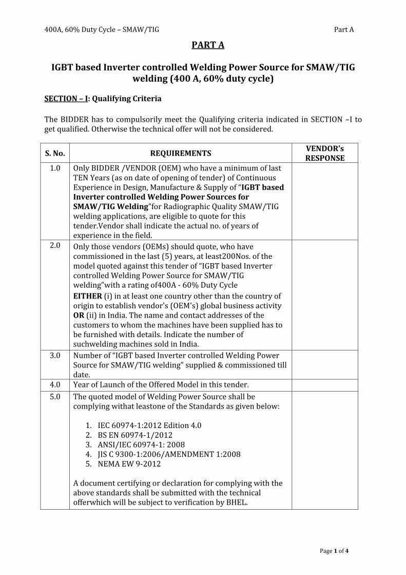
PART A
IGBT based Inverter controlled Welding Power Source for SMAW/TIG welding (400 A, 60% duty cycle)
SECTION – I: Qualifying Criteria
The BIDDER has to compulsorily meet the Qualifying criteria indicated in SECTION –I to get qualified. Otherwise the technical offer will not be considered.
S. No. REQUIREMENTS VENDOR’s RESPONSE
1.0 Only BIDDER /VENDOR (OEM) who have a minimum of last TEN Years (as on date of opening of tender) of Continuous Experience in Design, Manufacture & Supply of “IGBT based Inverter controlled Welding Power Sources for SMAW/TIG Welding”for Radiographic Quality SMAW/TIG welding applications, are eligible to quote for this tender.Vendor shall indicate the actual no. of years of experience in the field.
2.0 Only those vendors (OEMs) should quote, who have commissioned in the last (5) years, at least200Nos. of the model quoted against this tender of “IGBT based Inverter controlled Welding Power Source for SMAW/TIG welding”with a rating of400A - 60% Duty Cycle
EITHER (i) in at least one country other than the country of origin to establish vendor's (OEM's) global business activity OR (ii) in India. The name and contact addresses of the customers to whom the machines have been supplied has to be furnished with details. Indicate the number of suchwelding machines sold in India.
3.0 Number of “IGBT based Inverter controlled Welding Power Source for SMAW/TIG welding” supplied & commissioned till date.
4.0 Year of Launch of the Offered Model in this tender.
5.0 The quoted model of Welding Power Source shall be complying withat leastone of the Standards as given below:
1. IEC 60974-1:2012 Edition 4.0 2. BS EN 60974-1/2012 3. ANSI/IEC 60974-1: 2008 4. JIS C 9300-1:2006/AMENDMENT 1:2008 5. NEMA EW 9-2012
A document certifying or declaration for complying with the above standards shall be submitted with the technical offerwhich will be subject to verification by BHEL.

400A, 60% Duty Cycle – SMAW/TIG Part A
Page 2 of 4
S. No. REQUIREMENTS VENDOR’s RESPONSE
6.0 Vendor to submit TWO Performance certificatessatisfying all the following conditions (as on original date of opening tender) (suggestive format is given as annexure): a) Performance Certificates from any TWO customers for
satisfactory performance of minimum 25 Nos of the quoted model against this tender, from each of the customers, for a minimum period of one year from the date of commissioning (as on original date of opening of tender), supplied in the last five years,EITHER(i) in the country other than the country of origin OR(ii) in India, especially from Heavy Engineering / Fabrication Public/Private sector companies like Utility Boiler Manufacturers, Ship Building, Heavy duty Site fabrication, Large Heat Exchanger & Pressure Vessels manufacturers etc.
b) Performance certificates to be submitted as Original Certificate or through E-mail directly from the customer. The original performance certificate may be returned after verification by BHEL, if required.
c) Full contact details of the customers from whom the performance certificatesare obtained are to be provided.
d) For obtaining the Performance certificate, a suggestive format is provided.
7.0 Indian bidders shall submit Audited financial results for the past three financial years (2010-11, 2011-12, 2012-13) and Foreign bidders shall submit D&B report covering past three financial years. The financial results shall be verified and evaluated to examine the financial health of the company. BHEL reserves the right to accept or reject the OEMs based on the assessment of their financial capability.
8.0 Servicing facility to be available in India. Details on Service-After-Sales Set-Up in India (Address of Agents / Service Centres), to be furnished compulsorily.
9.0 BHEL reserves the right to accept or reject the OEMs based on the assessment of their technical capability. BHEL reserves the right to verify the information provided by the Vendor for the referred machine at their referred customer's works. It shall be the responsibility of the vendor to facilitate the visit of BHEL's team at their referred customer works .The Travel, Board& Lodging expenses for BHEL Personnel shall be borne by BHEL. In case the information provided by vendor is found to be false/ incorrect, the offer shall be rejected.

400A, 60% Duty Cycle – SMAW/TIG Part A
Page 3 of 4
SECTION – II The BIDDER / VENDOR is requested to provide the following information:
S. No. REQUIREMENTS VENDOR’s RESPONSE
10.0 Details of Design Set-Up and Technology Back-Up (R & D Centre) available with the OEM.
11.0 Details on Standards followed in Design and Testing of Welding Machines (Copy of English Version of Standards / Design Codes followed shall be furnished with the Technical Offer).
12.0 Details of Quality System followed (Furnish the salient aspects of the Quality Assurance System followed)
13.0 Comprehensive Details, on PerformanceTesting of Welding Machines carried out at the Factory, to be furnished with theTechnical Offer.
14.0 The BIDDER shall give details about supply of similar welding machines to BHEL units if any with Make, Model and Year of Supply& Commissioning etc.
15.0 A complete reference list of Customers shall be furnished (preferably of Heavy Engg. Companies) to whom such offered model has been supplied in the last ten years with PO details, Qty., Year of commissioning with contact details of the customers.
16.0 Any Additional Data to supplement the manufacturing capability of the BIDDER.
SECTION – III The BIDDER to note:
S. No. PARTICULARS VENDOR’sRESPONSE
17.0 The BIDDER shall submit the offer in Two Parts– 1. Technical [with PART A & PART B]& 2. Commercial and Price Bid.
18.0 The VENDOR’sRESPONSE against each clause in PART A & B of the offer should be filled by the BIDDER compulsorily with complete details.
19.0 The BIDDER shall assure a continuous support for Spares and Service for Ten Years, from the date of commissioning of the equipment at BHEL Works.
20.0 The Technical Offer shall be supported by Product Catalogue and Data Sheets in original and complete technical details / literature on the quoted models of Welding Powersources.

400A, 60% Duty Cycle – SMAW/TIG Part A
Page 4 of 4
21.0 The Commercial Offer (given with the Technical Offer) shall contain the Scope of Supply and the Un-Priced Part of the Price-Bid, for confirmation.
The performance certificate should be produced on Customer’s Letter Head.
Suggestive Format of Performance Certificate
(On Customer’s letter head)
PERFORMANCE CERTIFICATE
1. Supplier of the machine : 2. Make & Model of the m/c : 3. Month & Year of Commissioning :
4. Quantity :
5. Machine Details
a) Type :
b) Capacity in Amp. :
c) Duty Cycle :
6. Application of the welding power sources:
7. Performance of the Machine : Satisfactory / Good / Average / Not Satisfactory
(Strike off whichever is not applicable) 8. After sales service : Satisfactory / Good / Average / Not Satisfactory
(Strike off whichever is not applicable) 9. Any Other remarks :
Date: Signature & Seal of the Authority Issuing the Performance Certificate

40
0A
, 60
% D
uty
Cy
cle–SMA
W/T
IG
Page 1
of 9
Te
chn
ical S
pe
cificatio
n - P
AR
T B
IGB
T b
ase
dIn
ve
rter co
ntro
lled
We
ldin
g P
ow
er S
ou
rce fo
r SM
AW
/TIG
We
ldin
g
(40
0 A
mp
s, 60
% D
uty
Cy
cle)
S. n
o.
BH
EL
SP
EC
IFIC
AT
ION
O
FF
ER
BY
BID
DE
R
1.0
A
PP
LIC
AT
ION
:
1.1
T
he p
rop
osed
Weld
ing M
achin
e is inten
ded
for M
anu
al Arc W
eldin
g Pro
cess (SMA
W)
and
also M
anu
al TIG
weld
ing p
rocess fo
r pro
du
cing R
adio
graph
ic Qu
ality W
elds lik
e Bu
tt Jo
ints, F
illet Weld
s, and
Do
ub
le Gro
ov
e Weld
s com
ing in
High
Pressu
re Vessels u
sing 2
.5
mm
to 5
.0 m
m d
ia.basic co
ated stick
electrod
es.
2.0
P
OW
ER
SO
UR
CE
FE
AT
UR
ES
2.1
T
ype
Po
wer
sou
rce sh
all b
e IG
BT
b
ased
Inverter
Co
ntro
lled
and
cap
able o
f deliverin
g a Co
nstan
t Direct C
urren
t (in D
CE
P an
d
DC
EN
mo
des o
f weld
ing o
peratio
ns).
2.2
Sw
itchin
g Freq
uen
cy
BID
DE
R h
as to in
dicate th
e Switch
ing F
requ
ency
of th
e Inv
erter C
ircuit an
d th
e mak
e of IG
BT
used
.
2.3
C
urren
t Ratin
g 4
00
A @
60
% D
uty
Cycle
2
.4
Op
erating R
ange fo
r W
eldin
g Cu
rrent
20
A
to
4
00
A
(with
step
less
variation
C
on
tinu
ou
sly ad
justab
le)
2.5
O
pen
Circu
it Vo
ltage P
referred O
CV
is 70
to 7
5 V
. BID
DE
R to
men
tion
the O
pen
C
ircuit V
oltage fo
r the o
ffered P
ow
er sou
rce
2.6
C
urren
t Settin
g T
he v
ariation
in th
e set value o
f the w
eldin
g curren
t to th
e actu
al value sh
all no
t exceed 1
%.
2.7
C
urren
t Co
ntro
l C
urren
t con
trol / reg
ulatio
n sh
all be p
rovid
ed in
the F
ron
t P
anel o
f Po
wer so
urce an
d also
in th
e Rem
ote C
on
trol U
nit b
y
kn
ob
con
trol.
40
0A
, 60
% D
uty
Cy
cle–SMA
W/T
IG
Page 2
of 9
S. n
o.
BH
EL
SP
EC
IFIC
AT
ION
O
FF
ER
BY
BID
DE
R
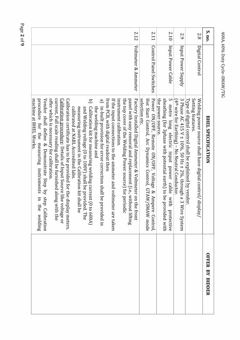
2.8
D
igital Co
ntro
l W
eldin
g po
wer so
urce sh
all have d
igital con
trol/ d
isplay
/ Settin
g features.
Typ
e of d
igital con
trol sh
all be exp
lained
by ven
do
r.
2.9
In
pu
t Po
wer Su
pp
ly
3 P
hase A
C 4
15
V ±
10
%, 5
0 H
z ± 2
%, th
rou
gh a 3
Wire System
(4
th wire fo
r Earth
ing) –
No
Neu
tral Co
nd
ucto
r.
2.1
0
Inp
ut P
ow
er Cab
le 5
m
etre lo
ng
electric in
pu
t p
ow
er cab
le w
ith
pro
tective sh
eathin
g (for 3
ph
ase with
po
tential earth
) to b
e pro
vided
with
th
e po
wer so
urce.
2.1
1
Co
ntro
l Pan
el Switch
es P
ow
er ON
/OF
F, R
emo
te ON
/OF
F, V
oltage &
Am
pere C
on
trol,
Ho
t Start Co
ntro
l, Arc D
ynam
ics Co
ntro
l, GT
AW
/SMA
W m
od
e selectio
n etc.
2.1
2
Vo
ltmeter &
Am
meter
Facto
ry In
stalled D
igital Am
meter &
Vo
ltmeter o
n th
e fron
t p
anel w
ith easy
remo
val and
replacem
ent (i.e., w
itho
ut liftin
g th
e top
cover o
f the W
eldin
g Po
wer so
urce) fo
r perio
dic
instru
men
t calibratio
n.
If the in
pu
t con
nectio
ns to
the am
meter an
d vo
ltmeter are tak
en
from
PC
B, w
ith d
igital reado
ut th
en
a) in
-bu
ilt pro
vision
for erro
r correctio
n sh
all be p
rovid
ed in
th
e weld
ing m
achin
e and
b
) C
alibratio
n k
it for m
easurin
g weld
ing cu
rrent (0
to 6
00
A)
and
Weld
ing vo
ltage (0 to
10
0V
) shall b
e pro
vided
. Th
e m
easurin
g instru
men
t in th
e Calib
ration
kit sh
all be
calibrated
at NA
BL
Accred
ited lab
s. C
alibratio
n certificate h
as to b
e pro
vided
for th
e disp
lay m
eters. C
alibratio
n p
roced
ure: D
etails of In
pu
t Sou
rce like vo
ltage or
curren
t, Fu
ll scale readin
g shall b
e furn
ished
alon
g with
the
offer w
hich
is necessary fo
r calibratio
n.
Ven
do
r shall d
efine &
Dem
on
strate Step b
y step C
alibratio
n
pro
cedu
re fo
r th
e m
easurin
g in
strum
ents
in
the
weld
ing
mach
ine at B
HE
L W
ork
s.

40
0A
, 60
% D
uty
Cy
cle–SMA
W/T
IG
Page 3
of 9
S. n
o.
BH
EL
SP
EC
IFIC
AT
ION
O
FF
ER
BY
BID
DE
R
2.1
3
Arc Strik
e
Selection
for In
stantan
eou
s Arc Strik
e with
Ho
t Start for SM
AW
P
rocess.
2.1
4
Arc D
ynam
ics Co
ntro
l - E
lectron
ic Ind
uctan
ce V
ariable C
on
trol
Arc
dyn
amics
Co
ntro
l sh
all b
e b
uilt
in
the
mach
ine
for
min
imisin
g the sp
atter and
op
timisin
g weld
-bead
wettin
g action
d
urin
g w
eldin
g o
f sp
ecial m
aterials lik
e Stain
less Steel,
T9
1/P
91
, Inco
nel, in
add
ition
to C
arbo
n an
d L
ow
Allo
y Steels.
2.1
5
Insu
lation
C
lass "H
"
– sh
all b
e p
rovid
ed
to
suit
Tro
pical
Wo
rkin
g C
on
ditio
ns
2.1
6
Mach
ine P
rotectio
n
IP 2
3 –
Degree o
f Pro
tectio
n
2
.17
M
achin
e Co
olin
g T
he P
ow
er sou
rce shall featu
re a forced
air coo
ling sy
stem th
at en
sures ad
equ
ate coo
ling o
f the co
mp
on
ents w
hile p
reven
ting
du
st and
metal p
articles from
bein
g draw
n in
.
2.1
8
Fu
nctio
nal / E
lemen
tal D
esign P
rotectio
n/
op
erator safety
a) In
bu
ilt p
rotectio
n
for
the
IGB
T/P
ow
er so
urce
against
Th
ermal / O
verload
/ Sho
rt-Circu
it / Single o
r Tw
o P
hase
P
ow
er Inp
ut C
on
ditio
ns.
b)
All P
CB
s shall b
e sprayed
with
mo
uld
coatin
g to p
reven
t d
amage fro
m d
ust an
d grin
din
g particles.
c) M
achin
e Design
to en
sure p
rop
er earthin
g for th
e mach
ine
and
its perip
herals.
d)
Pro
tection
again
st electric
sho
ck
from
in
pu
t su
pp
ly fo
r en
surin
g op
erator safety.
2.1
9
Electro
magn
etic In
terference (E
MI)
Sup
pressio
n
a) P
ow
er so
urce
shall
be
equ
ipp
ed
with
a
suitab
le F
ilter N
etwo
rk
con
nected
to
th
e in
pu
t P
ow
er L
ine,
to
prev
ent
pro
pagatio
n o
f EM
I / HF
no
ise either in
to o
r ou
t of th
e Po
wer
sou
rce. b
) A
ll m
etal en
closu
res an
d
intern
al sh
ields
shall
prev
ent
radiated
EM
I. c)
BID
DE
R h
as to elab
orate th
e design
features to
meet th
e ab
ove req
uirem
ents.
40
0A
, 60
% D
uty
Cy
cle–SMA
W/T
IG
Page 4
of 9
S. n
o.
BH
EL
SP
EC
IFIC
AT
ION
O
FF
ER
BY
BID
DE
R
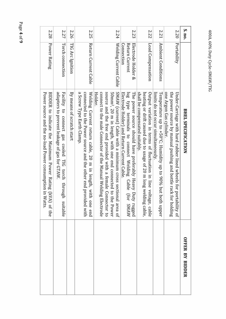
2.2
0
Po
rtability
U
nd
er-Carriage w
ith h
ard ru
bb
er lined
wh
eels for p
ortab
ility o
f th
e po
wer so
urce b
y man
ual p
ush
ing an
d b
ottle rack
for h
old
ing
on
e Argo
n G
as cylin
der.
2.2
1
Am
bien
t Co
nd
ition
s T
emp
erature u
p to
+5
0°C
; Hu
mid
ity up
to 9
0%
bu
t bo
th u
pp
er lim
its do
no
t occu
r simu
ltaneo
usly.
2.2
2
Lo
ad C
om
pen
sation
O
utp
ut v
ariation
in term
s of flu
ctuatio
n in
line vo
ltage, cable
heatin
g or d
rift caused
du
e to u
sage of 2
0 m
lon
g weld
ing cab
le, sh
all be co
mp
ensated
suitab
ly.
2.2
3
Electro
de H
old
er &
Retu
rn C
urren
t C
on
nectio
n
Th
e po
wer so
urce sh
ou
ld h
ave preferab
ly Heavy D
uty
rugged
lu
g ty
pe
termin
als to
co
nn
ect W
eldin
g C
able
(for
SMA
W
Electro
de H
old
er) and
Retu
rn C
urren
t Cab
le.
2.2
4
Weld
ing C
urren
t Cab
le SM
AW
(curren
t) Cab
le with
a min
imu
m cro
ss section
al area of
50
mm
2, 20
m in
length
, with
on
e end
con
nected
to th
e Po
wer
sou
rce and
the free en
d p
rovid
ed w
ith a fem
ale Co
nn
ector to
co
nn
ect to th
e male C
on
necto
r of th
e Man
ual W
eldin
g Electro
de
Ho
lder.
2.2
5
Retu
rn C
urren
t Cab
le
Weld
ing C
urren
t return
cable, 2
0 m
in len
gth, w
ith o
ne en
d
con
nected
to th
e Po
wer so
urce an
d th
e oth
er end
pro
vided
with
a S
crew T
ype E
arth C
lamp
.
2.2
6
TIG
Arc Ign
ition
B
y mean
s of scratch
start
2.2
7
To
rch co
nn
ection
F
acility
to
con
nect
gas co
oled
T
IG
torch
th
rou
gh
suitab
le ad
apters to
prev
ent leak
age of gas fo
r GT
AW
.
2.2
8
Po
wer R
ating
BID
DE
R to
ind
icate the M
aximu
m P
ow
er Ratin
g (kV
A) o
f the
Po
wer so
urce an
d th
e no
-load
Po
wer co
nsu
mp
tion
in W
atts.

40
0A
, 60
% D
uty
Cy
cle–SMA
W/T
IG
Page 5
of 9
S. n
o.
BH
EL
SP
EC
IFIC
AT
ION
O
FF
ER
BY
BID
DE
R
2.2
9
Po
wer So
urce M
od
el T
o Sp
ecify the M
od
el of P
ow
er sou
rce Offered
. (M
etallic nam
e plate o
f the m
achin
e shall also
inclu
de d
etails lik
e nam
e of m
anu
facturer, Serial n
o, Y
ear of M
fg inp
ut p
ow
er in
k
VA
, in
pu
t vo
ltage, N
o.
of
ph
ase, o
peratin
g freq
uen
cy,
weigh
t of th
e un
it etc.)
3.0
R
EM
OT
E C
ON
TR
OL
UN
IT F
EA
TU
RE
S
3.1
A
pp
lication
R
emo
te co
ntro
l un
it shall b
e p
rovid
ed
for settin
g weld
ing
curren
t from
a distan
t wo
rk p
lace, in ad
ditio
n to
that p
rovid
ed
in th
e fron
t pan
el of th
e weld
ing p
ow
er sou
rce.
3.2
T
yp
e H
and
Op
erated (fo
r SMA
W) an
d fo
ot o
perated
(for G
TA
W)
with
10
m lo
ng co
ntro
l cable w
ith q
uick
-fix end
con
necto
rs. T
ype o
f remo
te con
trol (an
alog o
r digital) m
ay be sp
ecified.
3.3
C
urren
t Co
ntro
l Step
less regulatio
n o
f Weld
ing C
urren
t.
4.0
T
IG W
EL
DIN
G T
OR
CH
ES
4.1
A
pp
lication
Su
itable
for
GT
AW
p
rocess
and
fo
r th
e n
ature
of
weld
ing
wo
rks listed
un
der S. n
o. 1
.0 an
d co
mp
atible to
the w
eldin
g p
ow
ersou
rce offered
.
4.2
M
ake
Preferred
mak
es are Weld
Craft, A
bico
r Bin
zel or an
y oth
er rep
uted
mak
e acceptab
le to B
HE
L.
4.3
T
orch
con
figu
ration
T
he
torch
H
ead-gas
lens
&
no
zzles co
nfig
uratio
n
shall
be
suitab
le for p
erform
ing th
e follo
win
g: a)
Tu
be
bu
tt w
elds
in
close
pitch
tu
bu
lar p
anels
with
a
min
imu
m
clear gap
o
f 1
2m
m
betw
een
the
adjacen
t tu
bes(gas n
ozzle en
d d
iameter is to
be 1
1m
m fo
r a length
o
f 25
mm
). b
) R
oo
t GT
AW
pass w
eldin
g in a 9
0m
m (w
all thick
ness) p
ipe
bu
tt weld
s (gas no
zzle end
dia. is to
be 1
1m
m fo
r a length
o
f 45
mm
).

40
0A
, 60
% D
uty
Cy
cle–SMA
W/T
IG
Page 6
of 9
S. n
o.
BH
EL
SP
EC
IFIC
AT
ION
O
FF
ER
BY
BID
DE
R
4.4
C
able sh
eathin
g P
rotectiv
e sheath
ing to
be p
rovid
ed fo
r the T
IG T
orch
cables &
H
oses, to
with
stand
sho
pflo
or ro
ugh
use fo
r the en
tire length
o
f cables/h
oses.
4.5
G
as coo
led T
orch
a)
Cu
rrent ratin
g: 14
0 to
18
0 A
@ 1
00
% D
uty
Cycle.
b)
Cab
le length
: Aro
un
d 8
m.
5.0
S
CO
PE
OF
SU
PP
LY
: [Th
e sco
pe
of su
pp
ly sh
all co
nsist o
f the
follo
win
g, fo
r ea
ch m
ach
ine
]
5.1
W
eldin
g Po
wer so
urce w
ith T
ransp
ort T
rolley w
ith w
heels an
d in
tegrated A
rgon
gas C
ylin
der C
art (on
e gas cylind
er/bo
ttle on
ly).
5.2
C
on
trol U
nit In
tegrated w
ith P
ow
ersou
rce
5.3
P
ow
er sou
rce suitab
le for T
IG/G
TA
W w
ith scratch
start
5.4
H
and
Op
erated R
emo
te Co
ntro
l Un
it.
5.5
F
oo
t op
erated R
emo
te Co
ntro
l Un
it
5.6
Set o
f Inter-C
on
nectin
g Cab
les, Ad
apters , h
oses etc.
5.7
W
eldin
g Cab
le and
Weld
ing H
old
er
5.8
R
eturn
Cu
rrent C
able w
ith Screw
Typ
e Earth
Clam
p.
5.9
G
as coo
led T
IG w
eldin
g torch
5.1
0
Electrical &
Mech
anical Sp
ares for P
ow
ersou
rce & C
on
trol U
nit
5.1
1
Calib
ration
kit if n
ecessary
5.1
2
OP
TIO
NA
L:P
rogram
load
ershall b
e sup
plied
if the p
ow
er sou
rce is pre
-pro
gramm
ed.

40
0A
, 60
% D
uty
Cy
cle–SMA
W/T
IG
Page 7
of 9
S. n
o.
BH
EL
SP
EC
IFIC
AT
ION
O
FF
ER
BY
BID
DE
R
6.0
S
PA
RE
S :
6.1
P
ow
er Sou
rce A
ll ty
pe
of
Spare
Parts
requ
ired
for
2
years
of
trou
ble
free
op
eration
on
three sh
ift basis in
clud
ing th
e follo
win
g items are to
b
e com
pu
lsorily
qu
oted
(with
Un
it Rate).
a) IG
BT
Kit
b)
All T
ypes o
f Fu
ses c)
Co
ntro
l – Tran
sform
ers d
) P
rinted
Circu
it Bo
ards / P
CB
s – All T
ypes
e) R
ectifiers, Th
ermisto
rs, Cap
acitors
f) Sw
itches an
d K
no
bs
g) C
oo
ling F
an M
oto
r h
) A
mm
eter & V
oltm
eter i)
Po
tentio
meter
j) R
elays &
Tim
ers k
) R
eceptacles
l) C
on
trol C
able w
ith E
nd
Co
nn
ectors
m) F
ilters n
) W
eldin
g & R
eturn
Cab
le Co
nn
ectors
6.2
T
IG T
orch
co
nsu
mab
les C
om
plete
set o
f co
nsu
mab
le sp
ares fo
r ø
2.4
mm
T
un
gsten
electrod
e, ‘O’ R
ings, G
as lens, n
ozzle/d
iffusers, ceram
ic no
zzles (b
oth
ty
pes),
collet
bo
dies,
etc. fo
r o
ne
year tro
ub
le free
op
eration
are to b
e offered
with
un
it price.
6.3
R
emo
te Co
ntro
l Un
it C
om
plete S
et of Sp
ares for R
emo
te Co
ntro
l Un
it to b
e offered
.
7.0
O
& M
MA
NU
AL
S :
7.1
N
o. o
f Co
pies
On
e cop
y fo
r each m
achin
e
7.2
L
angu
age E
nglish

40
0A
, 60
% D
uty
Cy
cle–SMA
W/T
IG
Page 8
of 9
S. n
o.
BH
EL
SP
EC
IFIC
AT
ION
O
FF
ER
BY
BID
DE
R
7.3
So
ft Co
py
O
ne so
ft cop
y in
CD
-RO
M is to
be giv
en fo
r each m
achin
e, co
ntain
ing th
e details m
entio
ned
un
der C
lause S
l. No
. 6.0
/6.4
7.4
M
anu
al Details :
a) M
anu
al sh
all co
ntain
all
instru
ction
s fo
r m
achin
e in
stallation
and
weld
ing trial testin
g, in seq
uen
ce. b
) M
anu
al to
giv
e gen
eral circu
it
diagram
s, sh
ow
ing
the
interco
nn
ection
of vario
us elem
ents an
d also
details o
n
PC
Bs [P
rinted
Circu
it Bo
ard] lik
e tapp
ing
voltages, m
ain
electron
ic elemen
ts' specificatio
ns an
d ratin
gs, etc. c)
Man
ual to
give o
ther d
etails like tro
ub
le sho
otin
g chart,
weld
param
eters selection
for vario
us b
ase metals, etc.
d)
Master L
ist of P
arts & Sp
ares used
in th
e mach
ine w
ith
Mak
e, Mo
del, R
ating, P
art nu
mb
eretc.
8.0
G
EN
ER
AL
PO
INT
S :
8.1
B
ou
ght-O
ut Item
s a)
IGB
Ts u
sed in
the w
eldin
g po
wer so
urces sh
all be o
f H
ITA
CH
I, JAP
AN
/ DY
NE
X, U
.K/ F
UJI, JA
PA
N/ IX
YS, U
SA
/ P
OW
ER
EX
, USA
/ MIT
SUB
ISHI, JA
PA
N/ T
OSH
IBA
, JAP
AN
/ IN
FIN
EO
N, G
ER
MA
NY
/ SEM
IKR
ON
, GE
RM
AN
Ym
ake o
nly
. T
he m
anu
facturer’s o
riginal test certificate fo
r the IG
BT
s u
sed
in
the
po
wer
sou
rces sh
all b
e p
rovid
ed
with
th
e eq
uip
men
t. T
hese
shall
be
verified
du
ring
pre
-disp
atch
insp
ection
. b
) T
he B
ou
ght-O
ut Item
s - like M
oto
rs, ICs, R
elays, C
on
tactors,
Switch
es, E
lectron
ic E
lemen
ts, etc.,
used
in
th
e P
ow
er so
urce &
Co
ntro
l Un
it shall b
e of rep
uted
mak
es acceptab
le to
BH
EL
. c)
BID
DE
R h
as to fu
rnish
the m
ake o
f Bo
ugh
t-Ou
t Items, alo
ng
with
the o
ffer.
8.2
W
eight
Bid
der to
specify th
e Weigh
t of sin
gle po
wer so
urce
40
0A
, 60
% D
uty
Cy
cle–SMA
W/T
IG
Page 9
of 9
S. n
o.
BH
EL
SP
EC
IFIC
AT
ION
O
FF
ER
BY
BID
DE
R
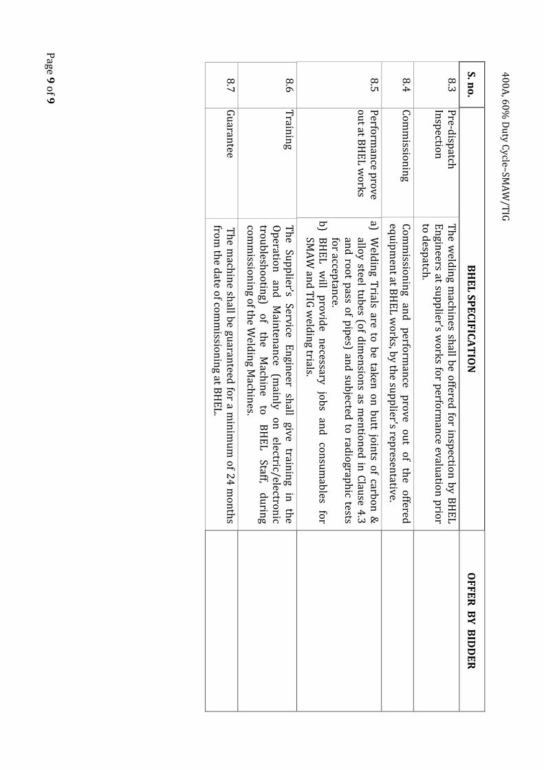
8.3
P
re-disp
atch
Insp
ection
T
he w
eldin
g mach
ines sh
all be o
ffered fo
r insp
ection
by
BH
EL
E
ngin
eers at sup
plier’s w
ork
s for p
erform
ance ev
aluatio
n p
rior
to d
espatch
.
8.4
C
om
missio
nin
g C
om
missio
nin
g an
d
perfo
rman
ce p
rove
ou
t o
f th
e o
ffered
equ
ipm
ent at B
HE
L w
ork
s, by th
e sup
plier's rep
resentativ
e.
8.5
P
erform
ance p
rove
ou
t at BH
EL
wo
rks
a) W
eldin
g Trials are to
be tak
en o
n b
utt jo
ints o
f carbo
n &
allo
y steel tub
es (of d
imen
sion
s as men
tion
ed in
Clau
se 4.3
an
d ro
ot p
ass of p
ipes) an
d su
bjected
to rad
iograp
hic tests
for accep
tance.
b)
BH
EL
w
ill p
rovid
e n
ecessary jo
bs
and
co
nsu
mab
les fo
r SM
AW
and
TIG
weld
ing trials.
8.6
T
rainin
g T
he
Sup
plier’s
Service E
ngin
eer sh
all giv
e train
ing
in
the
Op
eration
an
d
Main
tenan
ce (m
ainly
o
n
electric/electron
ic tro
ub
lesho
otin
g) o
f th
e M
achin
e to
B
HE
L
Staff, d
urin
g
com
missio
nin
g of th
e Weld
ing M
achin
es.
8.7
G
uaran
tee T
he m
achin
e shall b
e guaran
teed fo
r a min
imu
m o
f 24
mo
nth
s fro
m th
e date o
f com
missio
nin
g at BH
EL
.