SMARTRONIC MA - shop.ksb.com · Ref.8520.8041/7-EN SMARTRONIC MA R1310 positioner ... 412.2 O--Ring...
44
User instructions 42813892 SMARTRONIC MA Ref. 8520.8041/7-EN SMARTRONIC MA R1310 positioner SMARTRONIC MA Ex ia R1311 positioner
Transcript of SMARTRONIC MA - shop.ksb.com · Ref.8520.8041/7-EN SMARTRONIC MA R1310 positioner ... 412.2 O--Ring...
User instructions
42813892
SMARTRONIC MA Ref. 8520.8041/7-EN
SMARTRONIC MA R1310 positioner
SMARTRONIC MA Ex ia R1311 positioner
SMARTRONIC MA
2
SMARTRONIC MA
3
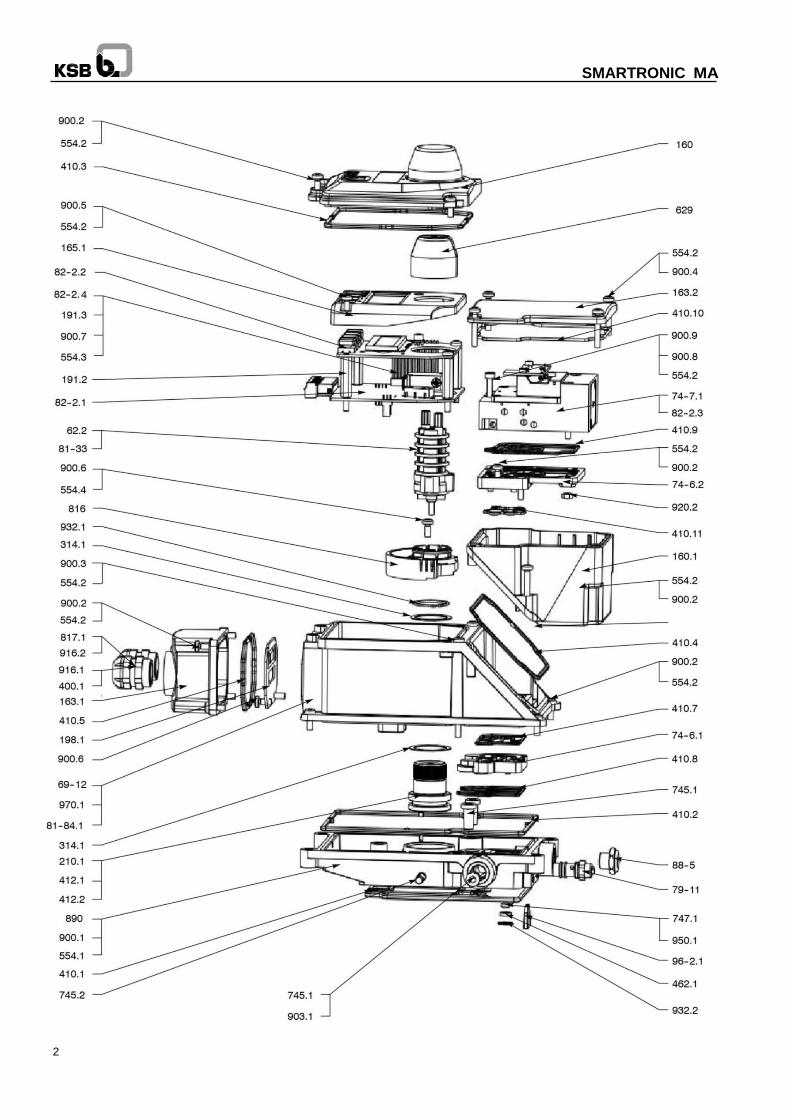
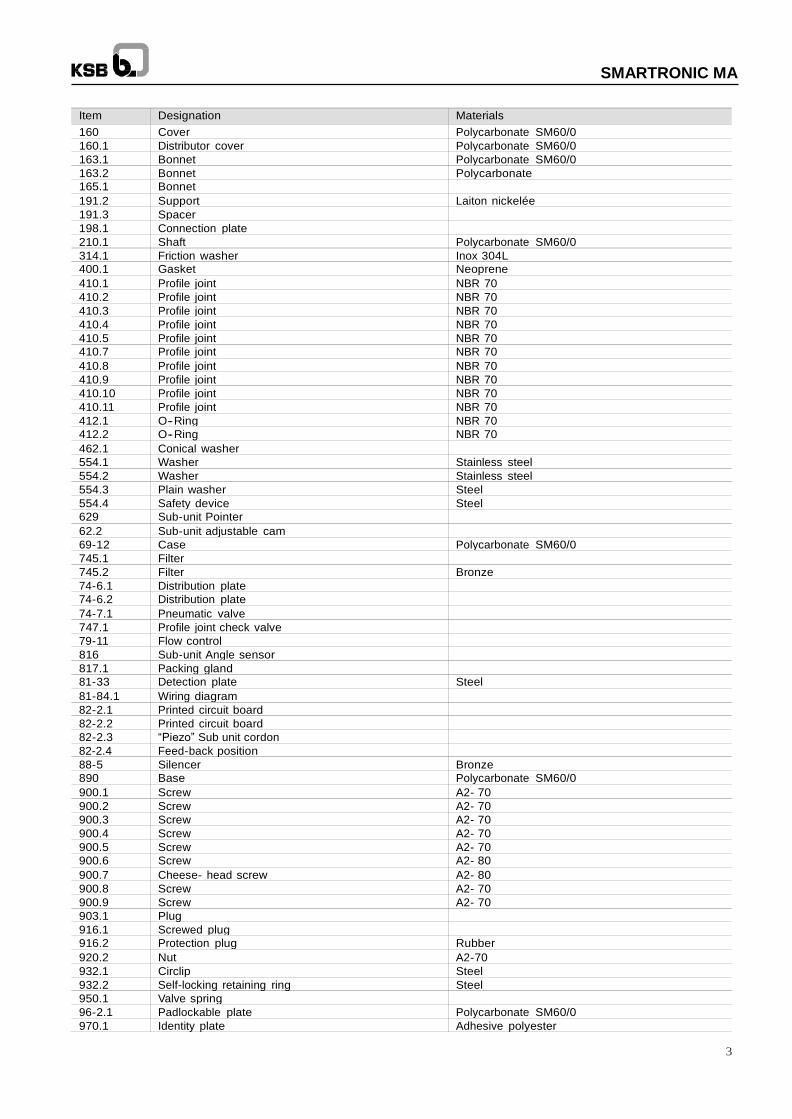
Item Designation Materials
160 Cover Polycarbonate SM60/0
160.1 Distributor cover Polycarbonate SM60/0
163.1 Bonnet Polycarbonate SM60/0
163.2 Bonnet Polycarbonate
165.1 Bonnet 191.2 Support Laiton nickelée
191.3 Spacer 198.1 Connection plate 210.1 Shaft Polycarbonate SM60/0
314.1 Friction washer Inox 304L
400.1 Gasket Neoprene
410.1 Profile joint NBR 70
410.2 Profile joint NBR 70
410.3 Profile joint NBR 70
410.4 Profile joint NBR 70
410.5 Profile joint NBR 70
410.7 Profile joint NBR 70
410.8 Profile joint NBR 70
410.9 Profile joint NBR 70
410.10 Profile joint NBR 70
410.11 Profile joint NBR 70
412.1 O-- Ring NBR 70
412.2 O-- Ring NBR 70
462.1 Conical washer 554.1 Washer Stainless steel
554.2 Washer Stainless steel
554.3 Plain washer Steel
554.4 Safety device Steel
629 Sub-unit Pointer 62.2 Sub-unit adjustable cam 69-12 Case Polycarbonate SM60/0
745.1 Filter 745.2 Filter Bronze
74-6.1 Distribution plate 74-6.2 Distribution plate 74-7.1 Pneumatic valve 747.1 Profile joint check valve 79-11 Flow control 816 Sub-unit Angle sensor 817.1 Packing gland 81-33 Detection plate Steel
81-84.1 Wiring diagram 82-2.1 Printed circuit board 82-2.2 Printed circuit board 82-2.3 “Piezo” Sub unit cordon 82-2.4 Feed-back position 88-5 Silencer Bronze
890 Base Polycarbonate SM60/0
900.1 Screw A2- 70
900.2 Screw A2- 70
900.3 Screw A2- 70
900.4 Screw A2- 70
900.5 Screw A2- 70
900.6 Screw A2- 80
900.7 Cheese- head screw A2- 80
900.8 Screw A2- 70
900.9 Screw A2- 70
903.1 Plug 916.1 Screwed plug 916.2 Protection plug Rubber
920.2 Nut A2-70
932.1 Circlip Steel
932.2 Self-locking retaining ring Steel
950.1 Valve spring 96-2.1 Padlockable plate Polycarbonate SM60/0
970.1 Identity plate Adhesive polyester
4
SMARTRONIC MA
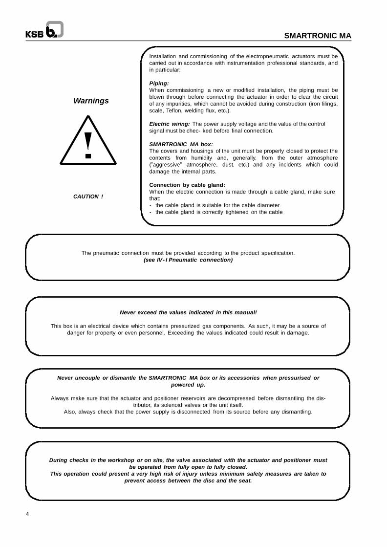
Installation and commissioning of the electropneumatic actuators must be
carried out in accordance with instrumentation professional standards, and
in particular:
Warnings
CAUTION !
Piping:
When commissioning a new or modified installation, the piping must be
blown through before connecting the actuator in order to clear the circuit
of any impurities, which cannot be avoided during construction (iron filings,
scale, Teflon, welding flux, etc.).
Electric wiring: The power supply voltage and the value of the control
signal must be chec- ked before final connection.
SMARTRONIC MA box:
The covers and housings of the unit must be properly closed to protect the
contents from humidity and, generally, from the outer atmosphere
(”aggressive” atmosphere, dust, etc.) and any incidents which could
damage the internal parts.
Connection by cable gland:
When the electric connection is made through a cable gland, make sure
that:
- the cable gland is suitable for the cable diameter
- the cable gland is correctly tightened on the cable
The pneumatic connection must be provided according to the product specification.
(see IV - I Pneumatic connection)
Never exceed the values indicated in this manual!
This box is an electrical device which contains pressurized gas components. As such, it may be a source of
danger for property or even personnel. Exceeding the values indicated could result in damage.
Never uncouple or dismantle the SMARTRONIC MA box or its accessories when pressurised or
powered up.
Always make sure that the actuator and positioner reservoirs are decompressed before dismantling the dis-
tributor, its solenoid valves or the unit itself.
Also, always check that the power supply is disconnected from its source before any dismantling.
During checks in the workshop or on site, the valve associated with the actuator and positioner must
be operated from fully open to fully closed.
This operation could present a very high risk of injury unless minimum safety measures are taken to
prevent access between the disc and the seat.
5
SMARTRONIC MA
Contents
Page
I - Introduction 7
I- 1 General 7
I- 2 Operating principle 7
I- 3 Technical characteristics 8
II - Assembly on pneumatic actuator 9
II - 1 ACTAIR 3 to 200, ACTAIR NG 2 to 160, DYNACTAIR 1.5 to 100 and DYNACTAIR NG 1 to 80 9
II - 2 ACTAIR NG 240 to 700 et DYNACTAIR NG 120 to 350 10
II - 2 ACTAIR 400 to 1600 and DYNACTAIR 200 to 800 and other ¼ turn actuators 11 II – 3 Linear actuators 12
III - Assembling the SMARTRONIC MA/Actuator assembly on the valve 14
IV - Pneumatic supply 14
IV - 1 Pneumatic connection 14
IV - 2 Mechanical adjustment of the operating time 15
IV - 3 Safety position on loss of current 16
V - Electric connections 17
V- 1 Connection housing 17
V- 2 Connections to the 4- 20mA current loop 17
V- 3 End stop connection 18
V- 4 Feed- back position (Option) 20
V- 5 HART console connection 20
VI - Local user interface 21
VI - 1 Cover 21
VI - 2 Main screen 22
VI - 3 Submenu screen 23
VII - Implementing the SMARTRONIC MA 25
VII - 1 Powering up 25
VII - 2 Autocalibration 25
VI - 2 - 1 Adjusting the angle sensor stroke 25
VI - 2 - 2 Starting auto-calibration 26
6
SMARTRONIC MA
VII - 3 Operating mode 26
VII - 3 - 1 Automatic mode 26
VII - 3 - 2 Manual mode 27
VII - 3 - 3 HART mode 27
VII - 4 Adjusting the end stop detectors 28
VII - 5 function of the SMARTRONIC MA positioner 29
VII - 5 - 1 Manual calibration 29
VII - 5 - 1 - 1 Positioning stroke 29
VII - 5 - 1 - 2 Positioning dead band 30
VII - 5 - 1 - 3 Positioner gain 30
VII - 5 - 2 Adjusting the setpoint according to the 4- 20 mA signal 31
VII - 5 - 3 Adjusting the valve closing direction 31
VII - 5 - 4 Product diagnosis 32
VII - 5 - 5 Configuring the main screen display 33
VII - 5 - 6 Configuring the main screen display 33
VII - 5 - 7 Displaying HART version - addressing data 33
VII - 5 - 8 HART compatibility 33
VIII - HART parameters 34
VIII - 1 Installing the Device Description (DD) file 34
VIII - 1 - 1 SDC625 34
VIII - 1 - 2 Pocket 375 34
VIII - 1 - 3 Simatic PDM 34
VIII - 2 Global organisation 34
VIII - 3 Detail of the file tree structure content 35
VIII - 3 - 1 ”KSB Hart Positioner” directory 35
VIII - 3 - 2 ”Operation” directory 35
VIII - 3 - 2 - 1 ”System” directory 35
VIII - 3 - 2 - 2 ”Endstop sensors” directory 35
VIII - 3 - 2 - 3 ”HART setpoint” directory 36
VIII - 3 - 3 ”Diagnosis” directory 36
VIII - 3 - 3 - 1 ”Number of Operations” directory 36
VIII - 3 - 3 - 2 ”Run time” directory 36
VIII - 3 - 4 ”Settings” directory 36
VIII - 3 - 4 - 1 ”Regulator” directory 36
VIII - 3 - 4 - 2 ”O/C fct point” directory 37
VIII - 3 - 4 - 3 ”Closing direction” directory 37
VIII - 3 - 4 - 4 ”Safety position” directory 37
VIII - 3 - 4 - 5 ”Ana. In/Out calib.” directory 37
VIII - 3 - 5 ”Info” directory 38
VIII - 3 - 5 - 1 ”Device” directory 38
VIII - 3 - 5 - 2 ”Positioner” directory 38
VIII - 3 - 5 - 3 ”Actuator” directory 38
VIII - 3 - 5 - 4 ”Valve” directory 39
VIII - 3 - 5 - 5 ”HART” directory 39
IX - Conformity 39
X - Operating faults - Causes and solutions 40
XI - Codes 41
XII - Spare parts kit 42
7
SMARTRONIC MA
I - Introduction
I -- 1 General
This manual describes the SMARTRONIC MA R1310 and SMARTRONIC MA Ex ia R1311 positioners. This device is
designed to control the quarter- turn actuators of the ACTAIR and DYNACTAIR range by direct surface mounting on the
standardised VDI/VDE 3845 interface. It provides both the direct pneumatic and mechanical link with the actuator
chambers.
The positioner can also be mounted on any other VDI/VDE 3845 actuator using an adapter kit (see §XII - Spare parts kit)
I - 2 Operating principle
This device is a sequential digital positioner. It is equipped with an on/off 3- position actuator control distributor with
valves. On loss of electrical power, the valve moves to the safety position configured when ordering the
SMARTRONIC MA positioner.
The actuator is positioned by energising either of the control solenoid valves.
These solenoid valves are controlled by the electronic board which reacts according to the difference between the
position (angle sensor signal) and the control signal by adopting one of the three possible states:
Positive difference = Opening
Zero difference = Position held (no action)
Negative difference = Closing
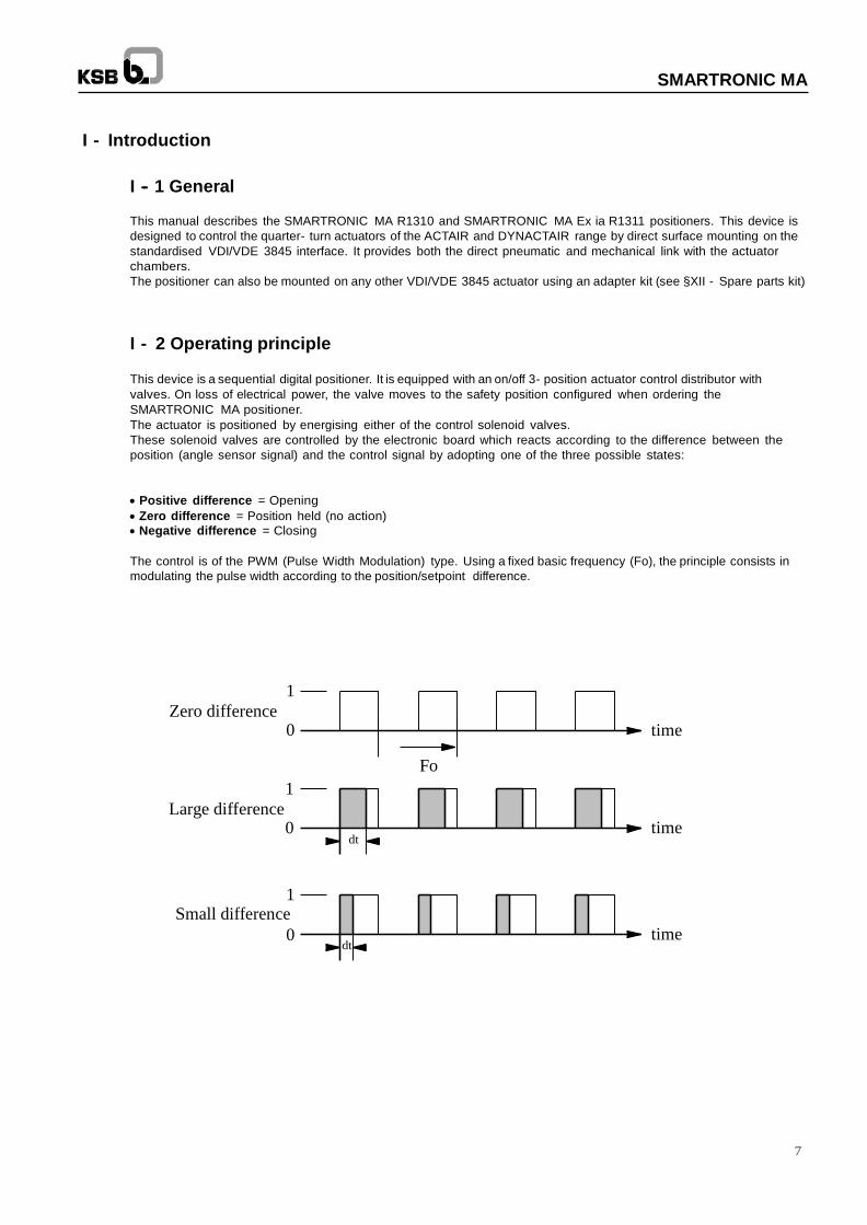
The control is of the PWM (Pulse Width Modulation) type. Using a fixed basic frequency (Fo), the principle consists in
modulating the pulse width according to the position/setpoint difference.
1
Zero difference 0
time
Fo
1
Large difference 0
dt
time
1
Small difference
0 dt
time

8
SMARTRONIC MA
I - 3 Technical Characteristics
Electric connections Accepts flexible conductors with end connector and with insulating entry cone
of cross- section 0.25 mm2 to 0,5 mm2
Weight 1,70 Kg
Environment
Standard protection class IP 67 according to EN 60529
Electromagnetic Compatibility Complies with European directive EMC 2004/108/EC according to standards NF EN 61000- 6- 2 et NF EN 61000- 6- 4
Climatic class - Storage temperature: - 30 ° C to + 80 ° C - Working temperature: - 20 ° C to + 80 ° C
Vibrations - According to IEC 68- 2- 6 Test Fc
Pneumatic distribution
Pressure connection Port 1/4” gas marked ”P” equipped with an internal filter on the base
Centralised exhaust connection Port 1/4” gas marked ”E” equipped with a silencer or connectable to exhaust network
Operating pressure 2 to 7 bar
Filtration level ISO 8573-1 (2001) Class 4 (< 15 m)
Dew point ISO 8573-1 (2001) Class 4 (<3 ° C and in all cases <5 ° C at ambient temperature)
Lubrication ISO 8573-1 (1991) Class 4 permanent (25mg/m3 admitted for 24h max)
Maximum flow rate 300 Nl/min (at 25 ° C)
Pneumatic consumption when idle < 0,4 Nl/min (at 25 ° C)
Electronic system
Electrical supply By 4- 20 mA current loop
Consumption from 40 mW (under 4mA) to 200mW (under 20mA)
Control signal 4 -- 20 mA
Minimum operating current 3,8 mA
Required load voltage 10 VDC
Protection against polarity inversions yes (up to 20 VDC)
Protection against over-voltage yes
Load resistance 500 to 515 Ohm under 20 mA
Static destruction limit 40 mA
Positioning characteristics
Hysteresis + dead band < 1%
Linearity < 1%
Repeatability < 0,5%
Variation law Linéaire
Offset adjustment (zero) and full scale adjustment
Manual adjustments using the interface screen+buttons
Standard direct action or indirect action - Dead band and gains automatically adjusted - Auto-calibration by pushbuttons
Position recopy (option)
Output 4- 20 mA two- wire, with galvanic / electronic isolation
Sampling period 0,4 seconds
Resolution CAN 16 bits
Linearity < 0,01%
Temperature effect from Tmin to Tmax < 0,05% - 10 ° C
Position detectors (option)
Adjustment on all the travel by cams
Inductive proximity detectors, mechanical microswitches or ATEX- certified inductive proximity detectors
9
SMARTRONIC MA
II - Assembly on pneumatic actuator
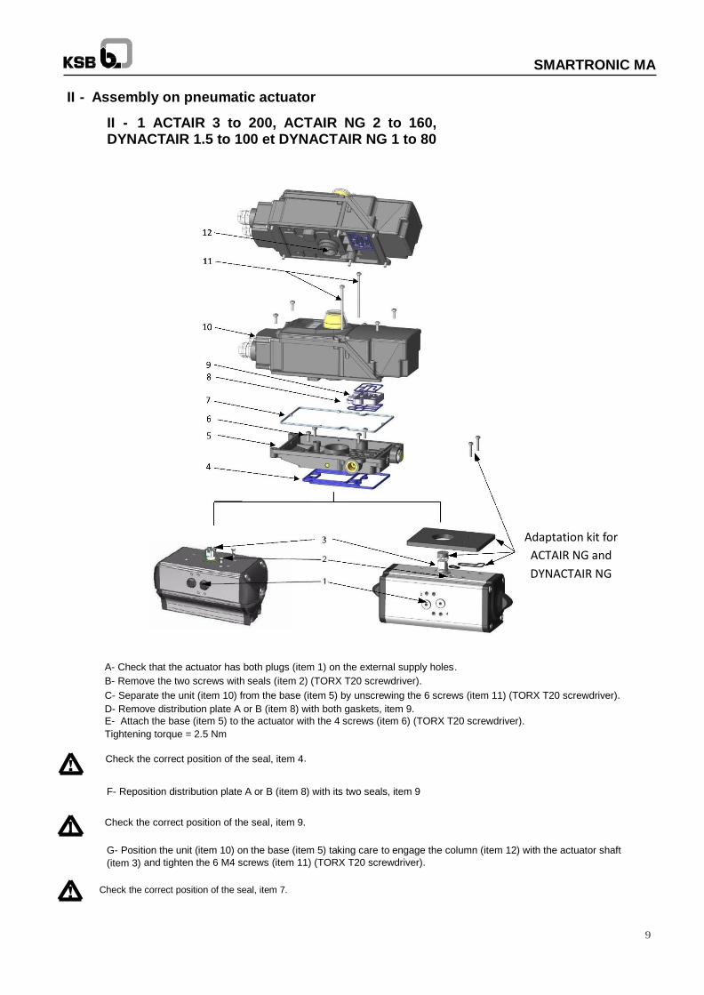
II - 1 ACTAIR 3 to 200, ACTAIR NG 2 to 160, DYNACTAIR 1.5 to 100 et DYNACTAIR NG 1 to 80
A- Check that the actuator has both plugs (item 1) on the external supply holes.
B- Remove the two screws with seals (item 2) (TORX T20 screwdriver).
C- Separate the unit (item 10) from the base (item 5) by unscrewing the 6 screws (item 11) (TORX T20 screwdriver).
D- Remove distribution plate A or B (item 8) with both gaskets, item 9.
E- Attach the base (item 5) to the actuator with the 4 screws (item 6) (TORX T20 screwdriver).
Tightening torque = 2.5 Nm
Check the correct position of the seal, item 4.
F- Reposition distribution plate A or B (item 8) with its two seals, item 9
Check the correct position of the seal, item 9.
G- Position the unit (item 10) on the base (item 5) taking care to engage the column (item 12) with the actuator shaft
(item 3) and tighten the 6 M4 screws (item 11) (TORX T20 screwdriver).
Check the correct position of the seal, item 7.
Adaptation kit for
ACTAIR NG and
DYNACTAIR NG
10
SMARTRONIC MA
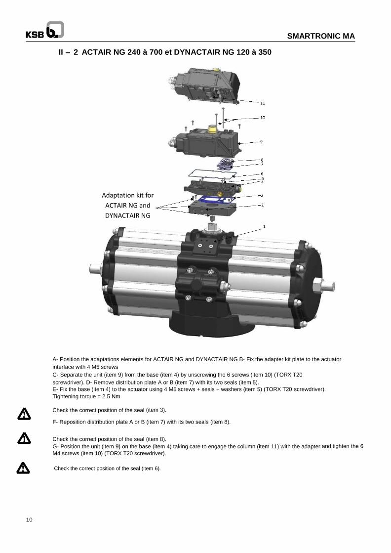
II – 2 ACTAIR NG 240 à 700 et DYNACTAIR NG 120 à 350
A- Position the adaptations elements for ACTAIR NG and DYNACTAIR NG B- Fix the adapter kit plate to the actuator
interface with 4 M5 screws
C- Separate the unit (item 9) from the base (item 4) by unscrewing the 6 screws (item 10) (TORX T20
screwdriver). D- Remove distribution plate A or B (item 7) with its two seals (item 5).
E- Fix the base (item 4) to the actuator using 4 M5 screws + seals + washers (item 5) (TORX T20 screwdriver).
Tightening torque = 2.5 Nm
Check the correct position of the seal (item 3).
F- Reposition distribution plate A or B (item 7) with its two seals (item 8).
Check the correct position of the seal (item 8).
G- Position the unit (item 9) on the base (item 4) taking care to engage the column (item 11) with the adapter and tighten the 6
M4 screws (item 10) (TORX T20 screwdriver).
Check the correct position of the seal (item 6).
Adaptation kit for
ACTAIR NG and
DYNACTAIR NG
11
SMARTRONIC MA
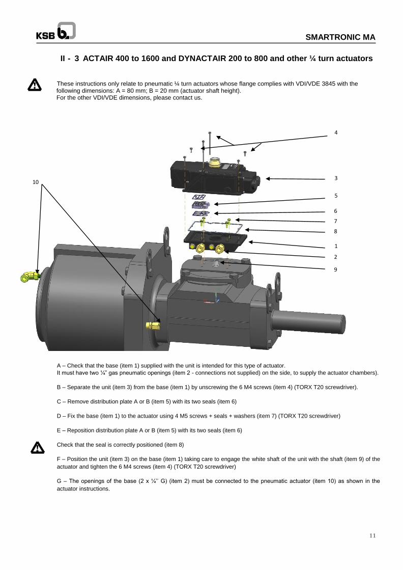
II - 3 ACTAIR 400 to 1600 and DYNACTAIR 200 to 800 and other ¼ turn actuators
These instructions only relate to pneumatic ¼ turn actuators whose flange complies with VDI/VDE 3845 with the
following dimensions: A = 80 mm; B = 20 mm (actuator shaft height). For the other VDI/VDE dimensions, please contact us.
10
A – Check that the base (item 1) supplied with the unit is intended for this type of actuator.
It must have two ¼” gas pneumatic openings (item 2 - connections not supplied) on the side, to supply the actuator chambers).
B – Separate the unit (item 3) from the base (item 1) by unscrewing the 6 M4 screws (item 4) (TORX T20 screwdriver).
C – Remove distribution plate A or B (item 5) with its two seals (item 6)
D – Fix the base (item 1) to the actuator using 4 M5 screws + seals + washers (item 7) (TORX T20 screwdriver)
E – Reposition distribution plate A or B (item 5) with its two seals (item 6)
Check that the seal is correctly positioned (item 8)
F – Position the unit (item 3) on the base (item 1) taking care to engage the white shaft of the unit with the shaft (item 9) of the
actuator and tighten the 6 M4 screws (item 4) (TORX T20 screwdriver)
G – The openings of the base (2 x ¼’’ G) (item 2) must be connected to the pneumatic actuator (item 10) as shown in the
actuator instructions.
1
2
3
4
5
6
7
8
9
12
SMARTRONIC MA
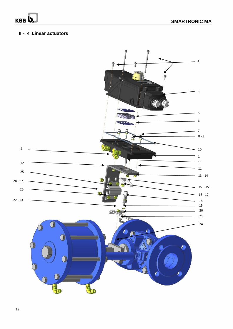
II - 4 Linear actuators
1
1’
3
4
5
6
10
8 - 9
11
7
2
12
25
28 - 27
26
22 - 23
13 - 14
15 – 15’
16 - 17
18
19
20
21
24
13
SMARTRONIC MA
These instructions only relate to linear pneumatic actuators which comply with VDI/VDE 3847 with rod-shaped pillars:
For the other actuator types, please contact us.
A – Check that the base (item 1) supplied with the unit is intended for this type of actuator.
It must have two ¼” gas pneumatic openings (item 2 - connections not supplied) on the side, to supply the actuator
chambers).
B – Separate the unit (item 3) from the base (item 1) by unscrewing the 6 M4 screws (item 4) (TORX T20 screwdriver).
C – Remove distribution plate A or B (item 5) with its two seals (item 6)
D – Fit a washer (item 9) and an O-ring (item 8) on each of the 4 M5 screws (item 7)
E – Tighten these 4 screws onto the base (item 1) with the 4 low-profile nuts (item 11)
F – Fix the base (item 1) to the plate (item 12) by tightening the 4 screws (item 7) and the washers (item 13) and nuts (item 14)
The base can be positioned every 180° according to requirements/ constraints
G – Mount the fluted rivet (item 15’) on the driver (item 15). Mount the unit onto the shaft (item 1’) and tighten with the nut (item
17) and washer (item 16)
H – Reposition distribution plate A or B (item 5) with its two seals (item 6)
Check that the seal is correctly positioned (item 10)
I – Position the unit (item 3) on the base (item 1) taking care to engage the white shaft of the unit with the shaft (item 1) of the
base and tighten the 6 M4 screws (item 4) (TORX T20 screwdriver)
J – Mount the sub-assembly (item 18) fitted with the washer (item19) on the plate (item 20) by tightening it onto the
counterplate (item 21)
K – Fix the assembled plate (item 20) onto the valve slider (item 24) with the screws (item 22) and washers (item 23).
L – Fix the plate (item 12) to one of the actuator pillars using the plate (item 25) by tightening the 4 screws (item 26) and the
washers (item 27) and nuts (item 28)
Adjust the position of the plate (item 12) and the sub-assembly (item 18) so that the sub-assembly (item 18) slides in the driver
(item 15) (without exiting) over the entire valve stroke.
14
SMARTRONIC MA
To be connected to the hole
2 of the actuator
To be connected to the hole
4 of the actuator
Exhaust
Direct pneumatic connection
Pneumatic connection by piping
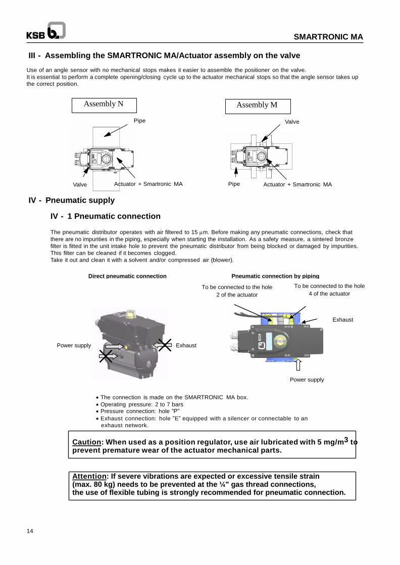
III - Assembling the SMARTRONIC MA/Actuator assembly on the valve
Use of an angle sensor with no mechanical stops makes it easier to assemble the positioner on the valve.
It is essential to perform a complete opening/closing cycle up to the actuator mechanical stops so that the angle sensor takes up
the correct position.
Assembly N Assembly M
Pipe Valve
Valve Actuator + Smartronic MA Pipe Actuator + Smartronic MA
IV - Pneumatic supply
IV - 1 Pneumatic connection
The pneumatic distributor operates with air filtered to 15 m. Before making any pneumatic connections, check that
there are no impurities in the piping, especially when starting the installation. As a safety measure, a sintered bronze
filter is fitted in the unit intake hole to prevent the pneumatic distributor from being blocked or damaged by impurities.
This filter can be cleaned if it becomes clogged.
Take it out and clean it with a solvent and/or compressed air (blower).
Power supply Exhaust
The connection is made on the SMARTRONIC MA box.
Operating pressure: 2 to 7 bars
Pressure connection: hole ”P”
Exhaust connection: hole ”E” equipped with a silencer or connectable to an
exhaust network.
Caution: When used as a position regulator, use air lubricated with 5 mg/m3 to prevent premature wear of the actuator mechanical parts.
Attention: If severe vibrations are expected or excessive tensile strain (max. 80 kg) needs to be prevented at the ¼" gas thread connections, the use of flexible tubing is strongly recommended for pneumatic connection.
Power supply
15
SMARTRONIC MA
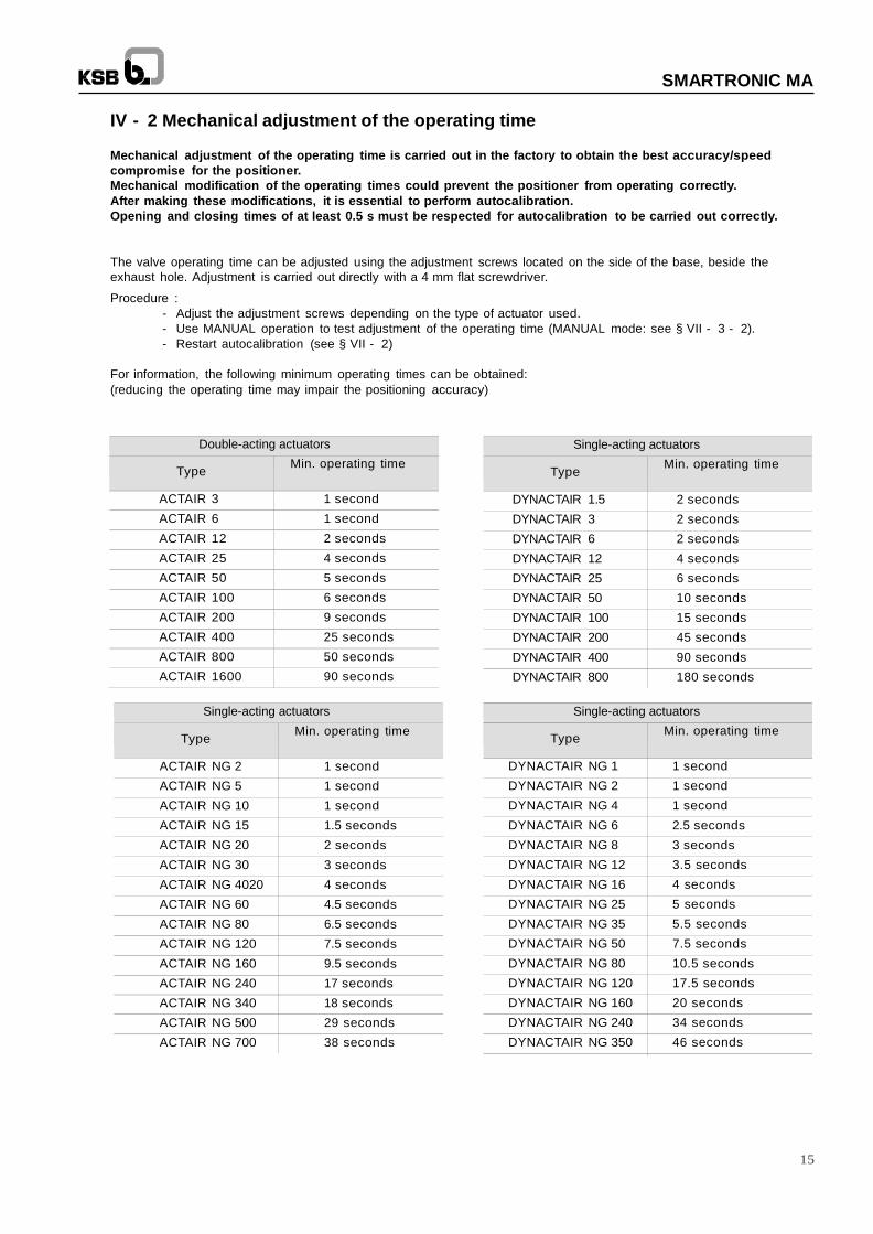
Single-acting actuators
Type Min. operating time
DYNACTAIR 1.5 2 seconds
DYNACTAIR 3 2 seconds
DYNACTAIR 6 2 seconds
DYNACTAIR 12 4 seconds
DYNACTAIR 25 6 seconds
DYNACTAIR 50 10 seconds
DYNACTAIR 100 15 seconds
DYNACTAIR 200 45 seconds
DYNACTAIR 400 90 seconds
DYNACTAIR 800 180 seconds
Single-acting actuators
Type Min. operating time
DYNACTAIR NG 1 1 second
DYNACTAIR NG 2 1 second
DYNACTAIR NG 4 1 second
DYNACTAIR NG 6 2.5 seconds
DYNACTAIR NG 8 3 seconds
DYNACTAIR NG 12 3.5 seconds
DYNACTAIR NG 16 4 seconds
DYNACTAIR NG 25 5 seconds
DYNACTAIR NG 35 5.5 seconds
DYNACTAIR NG 50 7.5 seconds
DYNACTAIR NG 80 10.5 seconds
DYNACTAIR NG 120 17.5 seconds
DYNACTAIR NG 160 20 seconds
DYNACTAIR NG 240 34 seconds
DYNACTAIR NG 350 46 seconds
DYNACTAIR 400 90 secondes
DYNACTAIR 800 180 secondes
IV - 2 Mechanical adjustment of the operating time
Mechanical adjustment of the operating time is carried out in the factory to obtain the best accuracy/speed
compromise for the positioner.
Mechanical modification of the operating times could prevent the positioner from operating correctly.
After making these modifications, it is essential to perform autocalibration.
Opening and closing times of at least 0.5 s must be respected for autocalibration to be carried out correctly.
The valve operating time can be adjusted using the adjustment screws located on the side of the base, beside the
exhaust hole. Adjustment is carried out directly with a 4 mm flat screwdriver.
Procedure :
- Adjust the adjustment screws depending on the type of actuator used.
- Use MANUAL operation to test adjustment of the operating time (MANUAL mode: see § VII - 3 - 2).
- Restart autocalibration (see § VII - 2)
For information, the following minimum operating times can be obtained:
(reducing the operating time may impair the positioning accuracy)
Double-acting actuators
Type Min. operating time
ACTAIR 3 1 second
ACTAIR 6 1 second
ACTAIR 12 2 seconds
ACTAIR 25 4 seconds
ACTAIR 50 5 seconds
ACTAIR 100 6 seconds
ACTAIR 200 9 seconds
ACTAIR 400 25 seconds
ACTAIR 800 50 seconds
ACTAIR 1600 90 seconds
Single-acting actuators
Type Min. operating time
ACTAIR NG 2 1 second
ACTAIR NG 5 1 second
ACTAIR NG 10 1 second
ACTAIR NG 15 1.5 seconds
ACTAIR NG 20 2 seconds
ACTAIR NG 30 3 seconds
ACTAIR NG 4020 4 seconds
ACTAIR NG 60 4.5 seconds
ACTAIR NG 80 6.5 seconds
ACTAIR NG 120 7.5 seconds
ACTAIR NG 160 9.5 seconds
ACTAIR NG 240 17 seconds
ACTAIR NG 340 18 seconds
ACTAIR NG 500 29 seconds
ACTAIR NG 700 38 seconds
16
SMARTRONIC MA
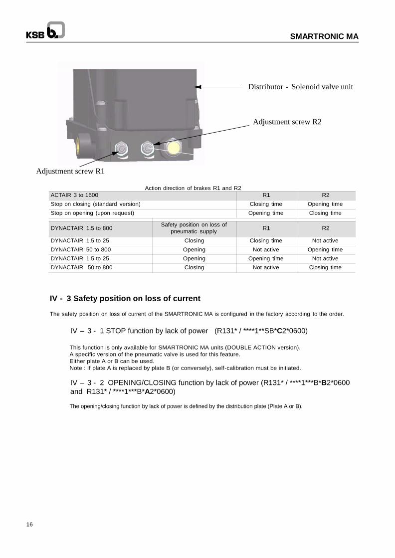
Distributor - Solenoid valve unit
Adjustment screw R2
Adjustment screw R1
Action direction of brakes R1 and R2
ACTAIR 3 to 1600 R1 R2
Stop on closing (standard version) Closing time Opening time
Stop on opening (upon request) Opening time Closing time
DYNACTAIR 1.5 to 800 Safety position on loss of
pneumatic supply
R1
R2
DYNACTAIR 1.5 to 25 Closing Closing time Not active
DYNACTAIR 50 to 800 Opening Not active Opening time
DYNACTAIR 1.5 to 25 Opening Opening time Not active
DYNACTAIR 50 to 800 Closing Not active Closing time
IV - 3 Safety position on loss of current
The safety position on loss of current of the SMARTRONIC MA is configured in the factory according to the order.
IV – 3 - 1 STOP function by lack of power (R131* / ****1**SB*C2*0600)
This function is only available for SMARTRONIC MA units (DOUBLE ACTION version).
A specific version of the pneumatic valve is used for this feature.
Either plate A or B can be used.
Note : If plate A is replaced by plate B (or conversely), self-calibration must be initiated.
IV – 3 - 2 OPENING/CLOSING function by lack of power (R131* / ****1***B*B2*0600
and R131* / ****1***B*A2*0600)
The opening/closing function by lack of power is defined by the distribution plate (Plate A or B).
17
SMARTRONIC MA
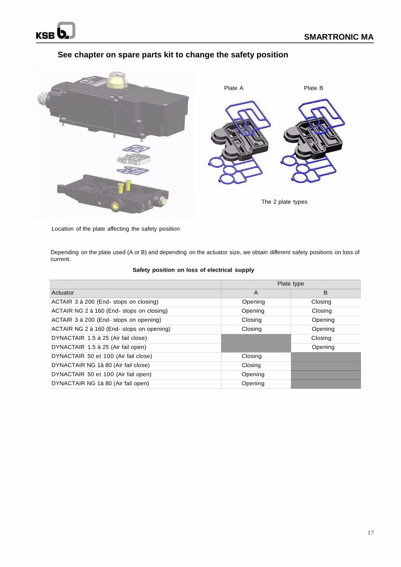
See chapter on spare parts kit to change the safety position
Location of the plate affecting the safety position
Plate A
Plate B
The 2 plate types
Depending on the plate used (A or B) and depending on the actuator size, we obtain different safety positions on loss of
current.
Safety position on loss of electrical supply
Plate type
Actuator A B
ACTAIR 3 à 200 (End- stops on closing) Opening Closing
ACTAIR NG 2 à 160 (End- stops on closing) Opening Closing
ACTAIR 3 à 200 (End- stops on opening) Closing Opening
ACTAIR NG 2 à 160 (End- stops on opening) Closing Opening
DYNACTAIR 1.5 à 25 (Air fail close) Closing
DYNACTAIR 1.5 à 25 (Air fail open) Opening
DYNACTAIR 50 et 100 (Air fail close) Closing DYNACTAIR NG 1à 80 (Air fail close) Closing DYNACTAIR 50 et 100 (Air fail open) Opening
DYNACTAIR NG 1à 80 (Air fail open) Opening
18
SMARTRONIC MA
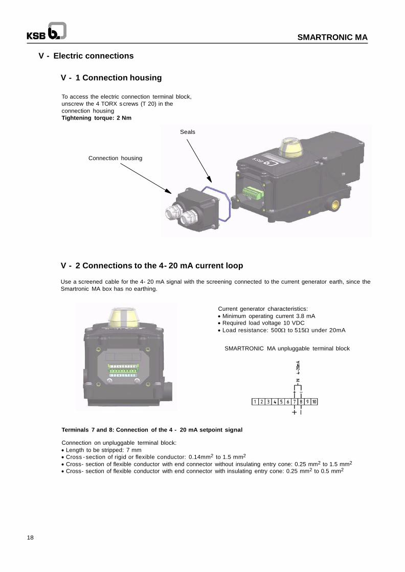
V - Electric connections
V - 1 Connection housing
To access the electric connection terminal block,
unscrew the 4 TORX screws (T 20) in the
connection housing
Tightening torque: 2 Nm
Seals
Connection housing
V - 2 Connections to the 4- 20 mA current loop
Use a screened cable for the 4- 20 mA signal with the screening connected to the current generator earth, since the
Smartronic MA box has no earthing.
Current generator characteristics:
Minimum operating current 3.8 mA
Required load voltage 10 VDC
Load resistance: 500 to 515 under 20mA
SMARTRONIC MA unpluggable terminal block
Terminals 7 and 8: Connection of the 4 - 20 mA setpoint signal
Connection on unpluggable terminal block:
Length to be stripped: 7 mm
Cross - section of rigid or flexible conductor: 0.14mm2 to 1.5 mm2
Cross- section of flexible conductor with end connector without insulating entry cone: 0.25 mm2 to 1.5 mm2
Cross- section of flexible conductor with end connector with insulating entry cone: 0.25 mm2 to 0.5 mm2
19
SMARTRONIC MA
Alternating current Direct current
220 V 127 V 48 V 24 V 115 V 48 V 24 V
Control of pure resistive load and static loads with isolation by
optocouplers
5
5
5
5
0,6
2
5
Control of static loads with transfor- mer isolation
2,5
3
4
4
0,3
1
3
Control of electromagnetic loads 2,5 3 4 4 0,04 0,15 0,6
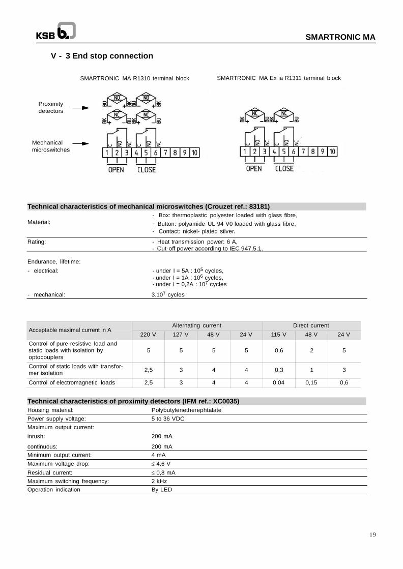
V - 3 End stop connection
Proximity
detectors
Mechanical
microswitches
SMARTRONIC MA R1310 terminal block SMARTRONIC MA Ex ia R1311 terminal block
Technical characteristics of mechanical microswitches (Crouzet ref.: 83181)
- Box: thermoplastic polyester loaded with glass fibre,
Material: - Button: polyamide UL 94 V0 loaded with glass fibre,
- Contact: nickel- plated silver.
Rating: - Heat transmission power: 6 A, - Cut-off power according to IEC 947.5.1.
Endurance, lifetime:
- electrical: - under I = 5A : 105 cycles,
- under I = 1A : 106 cycles,
- under I = 0,2A : 107 cycles
- mechanical: 3.107 cycles
Acceptable maximal current in A
Technical characteristics of proximity detectors (IFM ref.: XC0035)
Housing material: Polybutylenetherephtalate
Power supply voltage: 5 to 36 VDC
Maximum output current:
inrush: 200 mA
continuous: 200 mA
Minimum output current: 4 mA
Maximum voltage drop: 4,6 V
Residual current: 0,8 mA
Maximum switching frequency: 2 kHz
Operation indication By LED
20
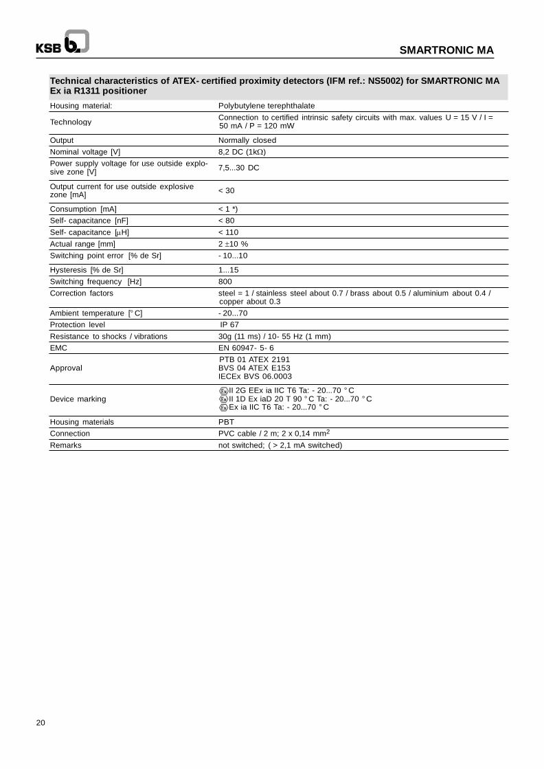
SMARTRONIC MA
Technology
Technical characteristics of ATEX- certified proximity detectors (IFM ref.: NS5002) for SMARTRONIC MA Ex ia R1311 positioner
Housing material: Polybutylene terephthalate
Connection to certified intrinsic safety circuits with max. values U = 15 V / I = 50 mA / P = 120 mW
Output Normally closed
Nominal voltage [V] 8,2 DC (1k)
Power supply voltage for use outside explo- sive zone [V]
7,5...30 DC
Output current for use outside explosive
zone [mA] < 30
Consumption [mA] < 1 *)
Self- capacitance [nF] < 80
Self- capacitance [H] < 110
Actual range [mm] 2 10 %
Switching point error [% de Sr] - 10...10
Hysteresis [% de Sr] 1...15
Switching frequency [Hz] 800
Correction factors steel = 1 / stainless steel about 0.7 / brass about 0.5 / aluminium about 0.4 / copper about 0.3
Ambient temperature [° C] - 20...70
Protection level IP 67
Resistance to shocks / vibrations 30g (11 ms) / 10- 55 Hz (1 mm)
EMC EN 60947- 5- 6
PTB 01 ATEX 2191 Approval
Device marking
BVS 04 ATEX E153 IECEx BVS 06.0003
II 2G EEx ia IIC T6 Ta: - 20...70 ° C II 1D Ex iaD 20 T 90 ° C Ta: - 20...70 ° C Ex ia IIC T6 Ta: - 20...70 ° C
Housing materials PBT
Connection PVC cable / 2 m; 2 x 0,14 mm2
Remarks not switched; ( > 2,1 mA switched)
21
SMARTRONIC MA
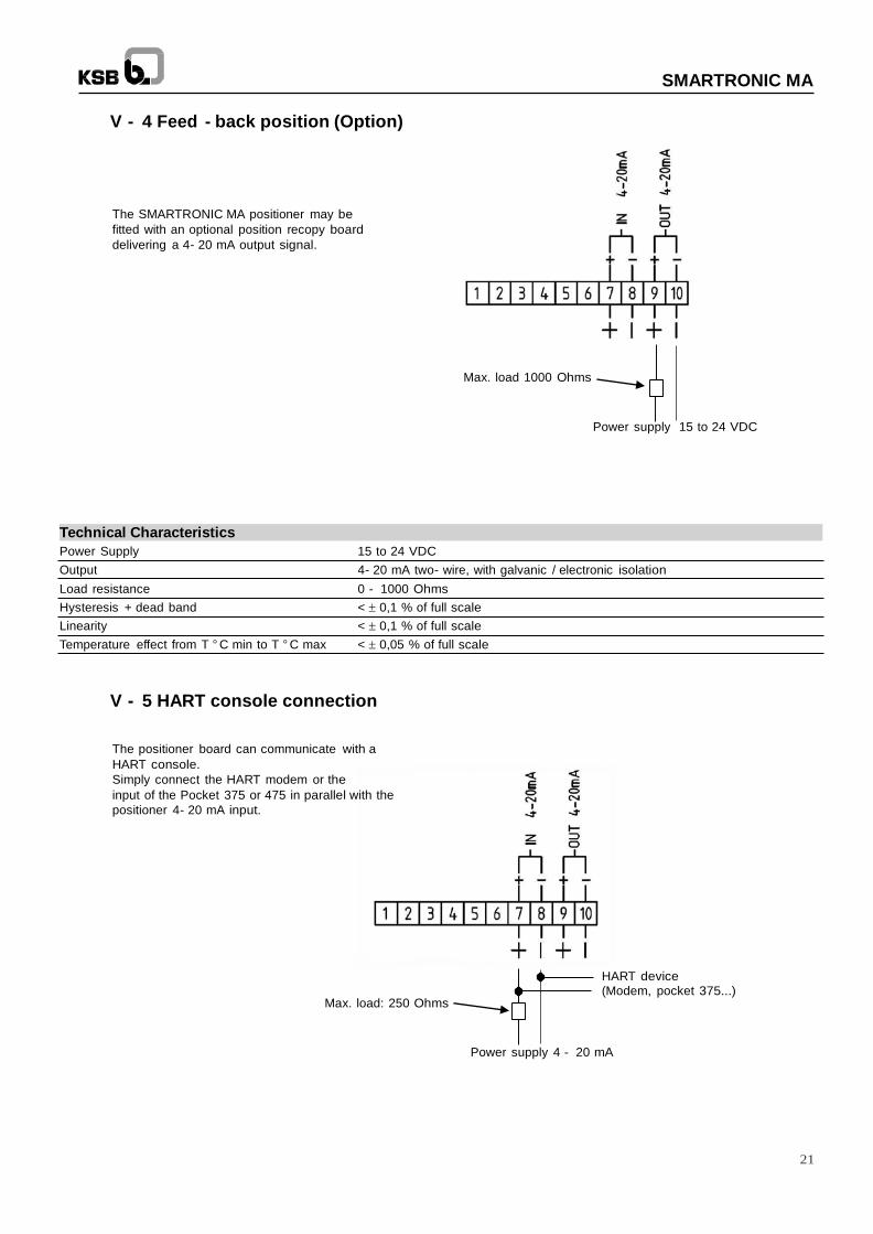
V - 4 Feed - back position (Option)
The SMARTRONIC MA positioner may be
fitted with an optional position recopy board
delivering a 4- 20 mA output signal.
Max. load 1000 Ohms
Power supply 15 to 24 VDC
Technical Characteristics
Power Supply 15 to 24 VDC
Output 4- 20 mA two- wire, with galvanic / electronic isolation
Load resistance 0 - 1000 Ohms
Hysteresis + dead band < 0,1 % of full scale
Linearity < 0,1 % of full scale
Temperature effect from T ° C min to T ° C max < 0,05 % of full scale
V - 5 HART console connection
The positioner board can communicate with a
HART console.
Simply connect the HART modem or the
input of the Pocket 375 or 475 in parallel with the
positioner 4- 20 mA input.
Max. load: 250 Ohms
HART device (Modem, pocket 375...)
Power supply 4 - 20 mA
22
SMARTRONIC MA
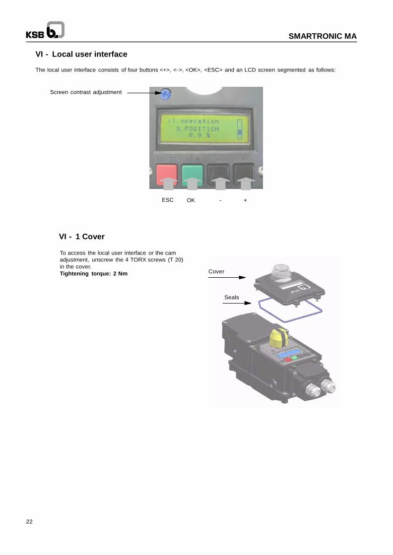
VI - Local user interface
The local user interface consists of four buttons <+>, <->, <OK>, <ESC> and an LCD screen segmented as follows:
Screen contrast adjustment
ESC OK - +
VI - 1 Cover
To access the local user interface or the cam
adjustment, unscrew the 4 TORX screws (T 20)
in the cover.
Tightening torque: 2 Nm
Cover
Seals
23
SMARTRONIC MA
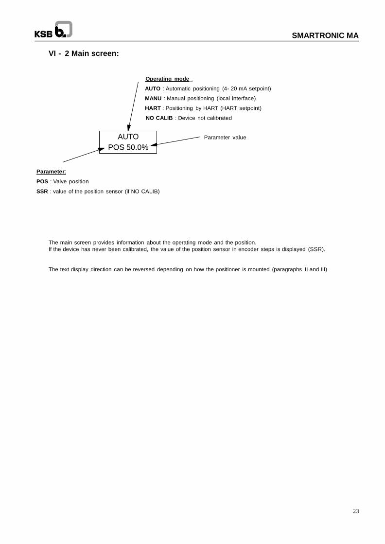
VI - 2 Main screen:
Operating mode :
AUTO : Automatic positioning (4- 20 mA setpoint)
MANU : Manual positioning (local interface)
HART : Positioning by HART (HART setpoint)
NO CALIB : Device not calibrated
AUTO
POS 50.0%
Parameter value
Parameter:
POS : Valve position
SSR : value of the position sensor (if NO CALIB)
The main screen provides information about the operating mode and the position.
If the device has never been calibrated, the value of the position sensor in encoder steps is displayed (SSR).
The text display direction can be reversed depending on how the positioner is mounted (paragraphs II and III)
24
SMARTRONIC MA
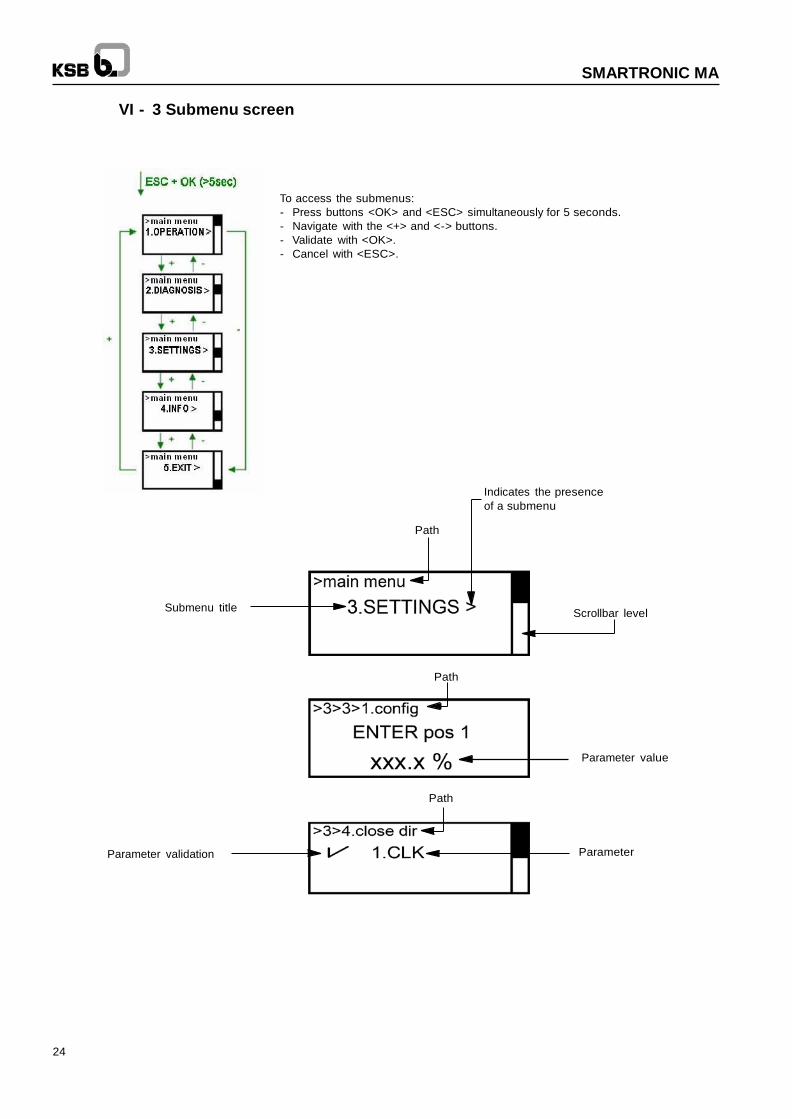
VI - 3 Submenu screen
To access the submenus:
- Press buttons <OK> and <ESC> simultaneously for 5 seconds.
- Navigate with the <+> and <-> buttons.
- Validate with <OK>.
- Cancel with <ESC>.
Indicates the presence
of a submenu
Path
Submenu title
Scrollbar level
Path
Parameter value
Path
Parameter validation Parameter
25
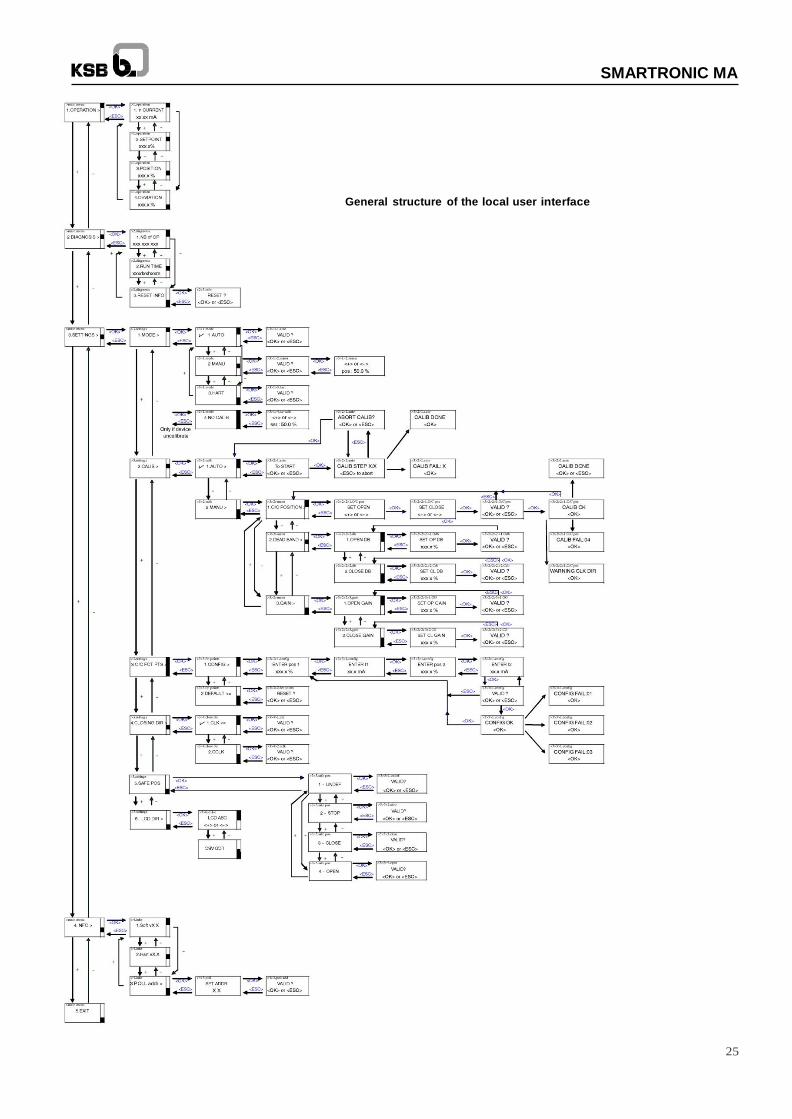
SMARTRONIC MA
General structure of the local user interface
26
SMARTRONIC MA
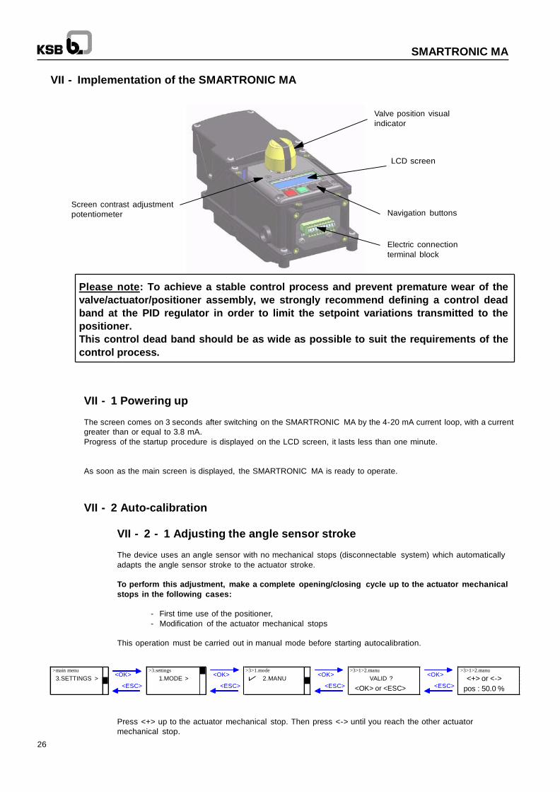
VII - Implementation of the SMARTRONIC MA
Valve position visual
indicator
LCD screen
Screen contrast adjustment
potentiometer
Navigation buttons
Electric connection
terminal block
Please note: To achieve a stable control process and prevent premature wear of the
valve/actuator/positioner assembly, we strongly recommend defining a control dead
band at the PID regulator in order to limit the setpoint variations transmitted to the
positioner.
This control dead band should be as wide as possible to suit the requirements of the
control process.
VII - 1 Powering up
The screen comes on 3 seconds after switching on the SMARTRONIC MA by the 4-20 mA current loop, with a current
greater than or equal to 3.8 mA.
Progress of the startup procedure is displayed on the LCD screen, it lasts less than one minute.
As soon as the main screen is displayed, the SMARTRONIC MA is ready to operate.
VII - 2 Auto-calibration
VII - 2 - 1 Adjusting the angle sensor stroke
The device uses an angle sensor with no mechanical stops (disconnectable system) which automatically
adapts the angle sensor stroke to the actuator stroke.
To perform this adjustment, make a complete opening/closing cycle up to the actuator mechanical
stops in the following cases:
- First time use of the positioner,
- Modification of the actuator mechanical stops
This operation must be carried out in manual mode before starting autocalibration.
>main menu >3.settings >3>1.mode >3>1>2.manu >3>1>2.manu
3.SETTINGS > <OK>
<ESC>
1.MODE > <OK>
<ESC>
2.MANU <OK>
<ESC>
VALID ?
<OK> or <ESC>
<OK>
<ESC> <+> or <->
pos : 50.0 %
Press <+> up to the actuator mechanical stop. Then press <-> until you reach the other actuator
mechanical stop.
27
SMARTRONIC MA
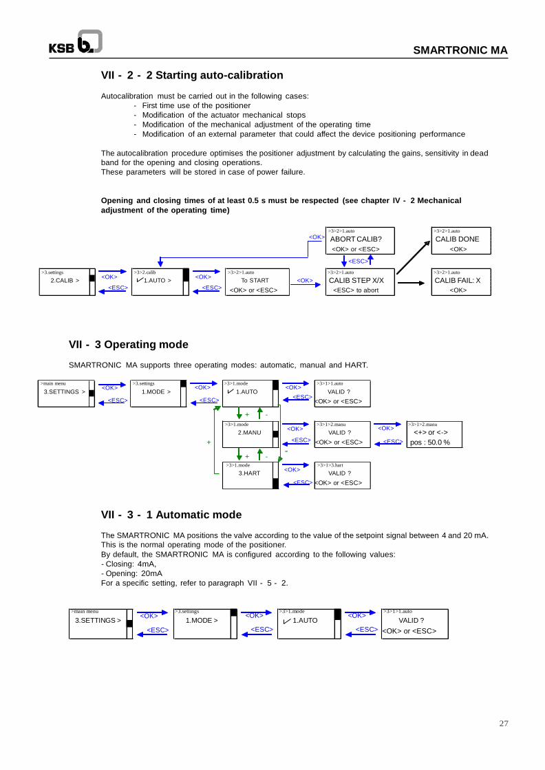
VII - 2 - 2 Starting auto-calibration
Autocalibration must be carried out in the following cases:
- First time use of the positioner
- Modification of the actuator mechanical stops
- Modification of the mechanical adjustment of the operating time
- Modification of an external parameter that could affect the device positioning performance
The autocalibration procedure optimises the positioner adjustment by calculating the gains, sensitivity in dead
band for the opening and closing operations.
These parameters will be stored in case of power failure.
Opening and closing times of at least 0.5 s must be respected (see chapter IV - 2 Mechanical
adjustment of the operating time)
<OK> >3>2>1.auto
ABORT CALIB?
<OK> or <ESC>
<ESC>
>3>2>1.auto
CALIB DONE
<OK>
>3.settings
>3>2.calib
>3>2>1.auto >3>2>1.auto
>3>2>1.auto
2.CALIB > <OK>
<ESC>
1.AUTO > <OK>
<ESC>
To START
<OK> or <ESC>
<OK> CALIB STEP X/X
<ESC> to abort
CALIB FAIL: X
<OK>
VII - 3 Operating mode
SMARTRONIC MA supports three operating modes: automatic, manual and HART.
>main menu >3.settings >3>1.mode >3>1>1.auto
<OK> <OK> <OK> 3.SETTINGS > 1.MODE > 1.AUTO VALID ?
<ESC> <ESC> <ESC>
+ -
<OK> or <ESC>
>3>1.mode >3>1>2.manu >3>1>2.manu
2.MANU <OK>
VALID ? <OK>
<+> or <->
+ <ESC> <OK> or <ESC>
-- + -
<ESC> pos : 50.0 %
>3>1.mode >3>1>3.hart
3.HART <OK>
VALID ?
<ESC> <OK> or <ESC>
VII - 3 - 1 Automatic mode
The SMARTRONIC MA positions the valve according to the value of the setpoint signal between 4 and 20 mA.
This is the normal operating mode of the positioner.
By default, the SMARTRONIC MA is configured according to the following values:
- Closing: 4mA,
- Opening: 20mA
For a specific setting, refer to paragraph VII - 5 - 2.
>main menu >3.settings >3>1.mode >3>1>1.auto
<OK> <OK> <OK> 3.SETTINGS > 1.MODE > 1.AUTO VALID ?
<ESC> <ESC> <ESC> <OK> or <ESC>
28
SMARTRONIC MA
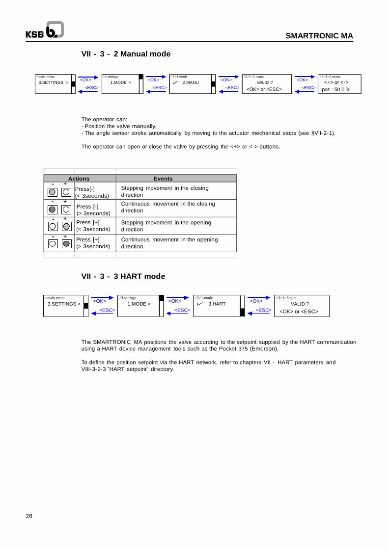
VII - 3 - 2 Manual mode
>main menu >3.settings >3>1.mode >3>1>2.manu >3>1>2.manu
3.SETTINGS > <OK>
<ESC>
1.MODE > <OK>
<ESC>
2.MANU <OK>
<ESC>
VALID ?
<OK> or <ESC>
<OK>
<ESC>
<+> or <->
pos : 50.0 %
The operator can:
- Position the valve manually,
- The angle sensor stroke automatically by moving to the actuator mechanical stops (see §VII-2-1).
The operator can open or close the valve by pressing the <+> or <-> buttons.
Actions Events
-- +
Press[-]
(< 3seconds)
Stepping movement in the closing
direction -- +
Press [-]
(> 3seconds)
Continuous movement in the closing
direction
-- + Press [+]
(< 3seconds)
Stepping movement in the opening
direction
-- + Press [+]
(> 3seconds)
Continuous movement in the opening
direction
VII - 3 - 3 HART mode
>main menu >3.settings >3>1.mode >3>1>3.hart
3.SETTINGS > <OK>
<ESC>
1.MODE > <OK>
<ESC>
3.HART <OK>
<ESC>
VALID ?
<OK> or <ESC>
The SMARTRONIC MA positions the valve according to the setpoint supplied by the HART communication
using a HART device management tools such as the Pocket 375 (Emerson).
To define the position setpoint via the HART network, refer to chapters VII - HART parameters and
VIII-3-2-3 ”HART setpoint” directory.

29
SMARTRONIC MA
VII - 4 Adjusting the end stop detectors
The cams are preset in the factory.
Their positions can be adjusted if the actuator mechanical stops are modified.
Cover
To access the cam adjustment, unscrew the
4 TORX screws (T 20) in the cover.
Tightening torque: 2 Nm
Visual index
- Make the electric connections of the end stops (see §V - 3)
- Bring the positioner to an extreme position (O or C) in manual mode (see §VII - 3 - 2)
- Remove the visual index
- Loosen the central screw of the cam (Torx screwdriver T20)
- Adjust triggering of the required contact by turning the coloured screw corresponding to the colour of the cam to be
adjusted (Red: closing; green: opening)
- Repeat the procedure for the opposite contact.
- Each cam is set independently and has no impact on the setting of the other cam.
- When the settings are finished, tighten the central screw of the cam moderately to lock the settings.
1 - Unscrew the central screw 2 - Set the cams 3 - Screw the central screw
30
SMARTRONIC MA
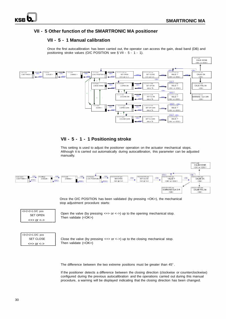
VII - 5 Other function of the SMARTRONIC MA positioner
VII - 5 - 1 Manual calibration
Once the first autocalibration has been carried out, the operator can access the gain, dead band (DB) and
positioning stroke values (O/C POSITION see § VII - 5 - 1 - 1).
>3>2>1.auto
CALIB DONE
<OK> or <ESC>
>main menu >3.settings
>3>2.calib >3>2>manu >3>2>2>1.O/C pos >3>2>2>1.O/C pos
<ESC> <OK>
>3>2>2>1.O/C pos >3>2>2>1.O/C pos
3.SETTINGS > <OK>
2.CALIB > <OK>
2.MANU > <OK>
1.O/C POSITION > <OK>
SET OPEN <OK> SET CLOSE <OK> VALID ? <OK> CALIB OK <ESC> <ESC> <ESC>
+ -
<ESC> <+> or <- > <+> or <->
<OK>
<OK> or <ESC> <OK>
<ESC>
>3>2>manu >3>2>2>2.db >3>2>2>2.>1.Odb >3>2>2>2.>1.Odb >3>2>2>1.O/C pos
2.DEAD BAND > <OK>
1.OPEN DB <OK>
SET OP DB <OK> VALID ? CALIB FAIL:04
<ESC>
-- + -
+
<ESC> xxx.x % <OK> or <ESC>
<OK>
<ESC>
<OK>
>3>2>2>2.db >3>2>2>2.>2.Cdb >3>2>2>2.>2,Cdb >3>2>2>1.O/C pos
<OK> 2.CLOSE DB SET CL DB
+ - <OK> VALID ? WARNING CLK DIR
<ESC> xxx.x % <OK> or <ESC> <OK>
<ESC> <OK>
>3>2>manu >3>2>2>3.gain >3>2>2>3>1.OG >3>2>2>3>1.OG
3.GAIN > <OK>
1.OPEN GAIN <OK>
SET OP GAIN <OK> VALID ? <ESC>
+ ---
<ESC> xxx.x % <OK> or <ESC>
<ESC> <OK>
>3>2>2>3.gain >3>2>2>3>2.CG >3>2>2>3>2.CG
2.CLOSE GAIN <OK>
SET CL GAIN <OK> VALID ?
<ESC> xxx.x % <OK> or <ESC>
VII - 5 - 1 - 1 Positioning stroke
This setting is used to adjust the positioner operation on the actuator mechanical stops.
Although it is carried out automatically during autocalibration, this parameter can be adjusted
manually.
Once the O/C POSITION has been validated (by pressing <OK>), the mechanical
stop adjustment procedure starts:
>3>2>2>1.O/C pos
SET OPEN
<+> or <->
>3>2>2>1.O/C pos
SET CLOSE
<+> or <->
Open the valve (by pressing <+> or <->) up to the opening mechanical stop.
Then validate (<OK>)
Close the valve (by pressing <+> or <->) up to the closing mechanical stop.
Then validate (<OK>)
The difference between the two extreme positions must be greater than 45° .
If the positioner detects a difference between the closing direction (clockwise or counterclockwise)
configured during the previous autocalibration and the operations carried out during this manual
procedure, a warning will be displayed indicating that the closing direction has been changed.
31
SMARTRONIC MA
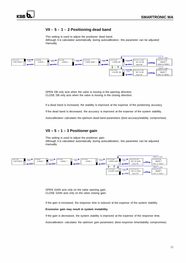
VII - 5 - 1 - 2 Positioning dead band
This setting is used to adjust the positioner dead band.
Although it is calculated automatically during autocalibration, this parameter can be adjusted
manually.
<ESC> <OK>
>main menu >3.settings >3>2.calib >3>2>manu >3>2>2>2.db >3>2>2>2.>1.Odb >3>2>2>2.>1.Odb
3.SETTINGS > <OK>
<ESC>
2.CALIB > <OK>
<ESC>
2.MANU > <OK>
<ESC>
2.DEAD BAND > <OK>
<ESC>
1.OPEN DB <OK>
<ESC>
SET OP DB
xxx.x %
<OK> VALID ?
<OK> or <ESC>
+ --- <ESC> <OK>
>3>2>2>2.db >3>2>2>2.>2.Cdb >3>2>2>2.>2,Cdb
2.CLOSE DB <OK>
SET CL DB <OK> VALID ?
<ESC> xxx.x % <OK> or <ESC>
OPEN DB only acts when the valve is moving in the opening direction.
CLOSE DB only acts when the valve is moving in the closing direction.
If a dead band is increased, the stability is improved at the expense of the positioning accuracy.
If the dead band is decreased, the accuracy is improved at the expense of the system stability.
Autocalibration calculates the optimum dead band parameters (best accuracy/stability compromise).
VII -- 5 -- 1 -- 3 Positioner gain
This setting is used to adjust the positioner gain.
Although it is calculated automatically during autocalibration, this parameter can be adjusted
manually.
>main menu >3.settings >3>2.calib
>3>2>manu >3>2>2>3.gain >3>2>2>3>1.OG
<ESC> <OK>
>3>2>2>3>1.OG
3.SETTINGS > <OK>
2.CALIB > <OK>
2.MANU > <OK>
3.GAIN > <OK>
1.OPEN GAIN <OK>
SET OP GAIN <OK> VALID ?
<ESC> <ESC> <ESC> <ESC>
+ ---
<ESC> xxx.x % <OK> or <ESC>
<ESC> <OK>
>3>2>2>3.gain >3>2>2>3>2.CG >3>2>2>3>2.CG
2.CLOSE GAIN <OK>
SET CL GAIN <OK> VALID ?
<ESC> xxx.x % <OK> or <ESC>
OPEN GAIN acts only on the valve opening gain.
CLOSE GAIN acts only on the valve closing gain.
If the gain is increased, the response time is reduced at the expense of the system stability.
Excessive gain may result in system instability.
If the gain is decreased, the system stability is improved at the expense of the response time.
Autocalibration calculates the optimum gain parameters (best response time/stability compromise).
32
SMARTRONIC MA
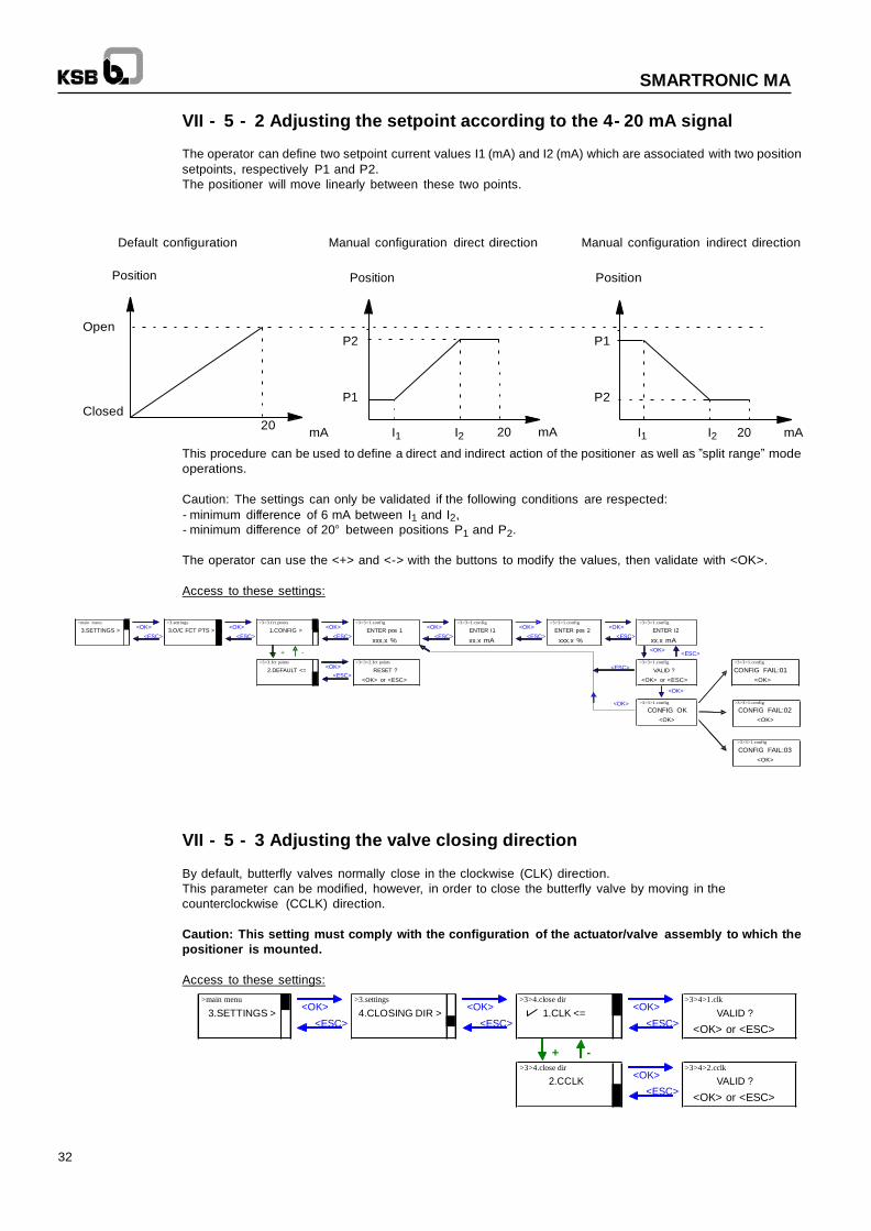
VII - 5 - 2 Adjusting the setpoint according to the 4- 20 mA signal
The operator can define two setpoint current values I1 (mA) and I2 (mA) which are associated with two position
setpoints, respectively P1 and P2.
The positioner will move linearly between these two points.
Default configuration Manual configuration direct direction Manual configuration indirect direction
Position Position Position
Open
Closed
P2 P1 P1 P2
20 mA I1 I2 20 mA I1 I2 20 mA
This procedure can be used to define a direct and indirect action of the positioner as well as ”split range” mode
operations.
Caution: The settings can only be validated if the following conditions are respected:
- minimum difference of 6 mA between I1 and I2, - minimum difference of 20° between positions P1 and P2.
The operator can use the <+> and <-> with the buttons to modify the values, then validate with <OK>.
Access to these settings:
>main menu >3.settings >3>3.fct points >3>3>1.config >3>3>1.config >3>3>1.config >3>3>1.config
3.SETTINGS > <OK>
<ESC> 3.O/C FCT PTS >
<OK>
<ESC> 1.CONFIG >
<OK>
<ESC> ENTER pos 1
<OK>
<ESC> ENTER I1
<OK>
<ESC> ENTER pos 2
<OK>
<ESC> ENTER I2
xxx.x % xx.x mA
+ -
xxx.x % xx.x mA
<OK> <ESC>
>3>3.fct points >3>3>2.fct points >3>3>1.config >3>3>1.config
2.DEFAULT <= <OK>
<ESC> RESET ?
<ESC> VALID ? CONFIG FAIL:01
<OK> or <ESC> <OK> or <ESC>
<OK>
<OK>
<OK> >3>3>1.config >3>3>1.config
CONFIG OK CONFIG FAIL:02
<OK> <OK>
>3>3>1.config
CONFIG FAIL:03
<OK>
VII - 5 - 3 Adjusting the valve closing direction
By default, butterfly valves normally close in the clockwise (CLK) direction.
This parameter can be modified, however, in order to close the butterfly valve by moving in the
counterclockwise (CCLK) direction.
Caution: This setting must comply with the configuration of the actuator/valve assembly to which the
positioner is mounted.
Access to these settings:
>main menu >3.settings >3>4.close dir >3>4>1.clk
3.SETTINGS > <OK>
<ESC> 4.CLOSING DIR >
<OK>
<ESC> 1.CLK <=
+ -
<OK>
<ESC> VALID ?
<OK> or <ESC>
>3>4.close dir >3>4>2.cclk
2.CCLK <OK>
<ESC> VALID ?
<OK> or <ESC>
33
SMARTRONIC MA
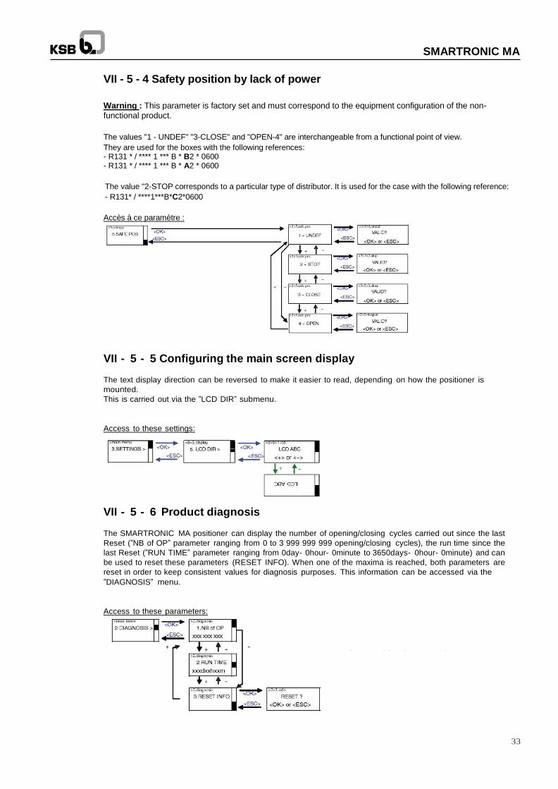
VII - 5 - 4 Safety position by lack of power
Warning : This parameter is factory set and must correspond to the equipment configuration of the non-
functional product.
The values "1 - UNDEF" "3-CLOSE" and "OPEN-4" are interchangeable from a functional point of view.
They are used for the boxes with the following references: - R131 * / **** 1 *** B * B2 * 0600 - R131 * / **** 1 *** B * A2 * 0600
The value "2-STOP corresponds to a particular type of distributor. It is used for the case with the following reference:
- R131* / ****1***B*C2*0600
Accès à ce paramètre :
VII - 5 - 5 Configuring the main screen display
The text display direction can be reversed to make it easier to read, depending on how the positioner is
mounted.
This is carried out via the ”LCD DIR” submenu.
Access to these settings:
VII - 5 - 6 Product diagnosis
The SMARTRONIC MA positioner can display the number of opening/closing cycles carried out since the last
Reset (”NB of OP” parameter ranging from 0 to 3 999 999 999 opening/closing cycles), the run time since the
last Reset (”RUN TIME” parameter ranging from 0day- 0hour- 0minute to 3650days- 0hour- 0minute) and can
be used to reset these parameters (RESET INFO). When one of the maxima is reached, both parameters are
reset in order to keep consistent values for diagnosis purposes. This information can be accessed via the
”DIAGNOSIS” menu.
Access to these parameters:
34
SMARTRONIC MA
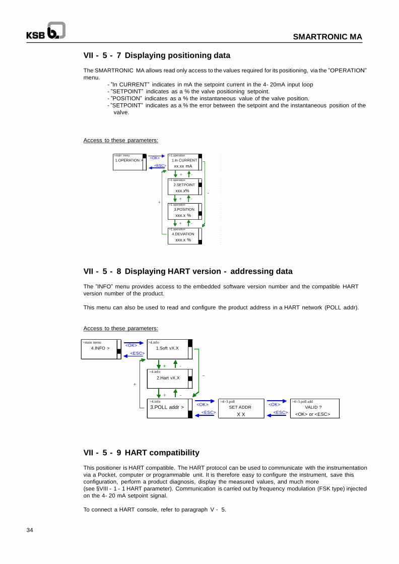
VII - 5 - 7 Displaying positioning data
The SMARTRONIC MA allows read only access to the values required for its positioning, via the ”OPERATION”
menu.
- ”In CURRENT” indicates in mA the setpoint current in the 4- 20mA input loop
- ”SETPOINT” indicates as a % the valve positioning setpoint.
- ”POSITION” indicates as a % the instantaneous value of the valve position.
- ”SETPOINT” indicates as a % the error between the setpoint and the instantaneous position of the
valve.
Access to these parameters:
>main menu >1.operation
1.OPERATION > <OK>
<ESC>
+
1.In CURRENT
xx.xx mA
+ - >1.operation
2.SETPOINT
xxx.x% --
+ -
>1.operation
3.POSITION
xxx.x %
+ -
>1.operation
4.DEVIATION
xxx.x %
VII - 5 - 8 Displaying HART version - addressing data
The ”INFO” menu provides access to the embedded software version number and the compatible HART
version number of the product.
This menu can also be used to read and configure the product address in a HART network (POLL addr).
Access to these parameters:
>main menu >4.info
4.INFO > <OK>
<ESC>
1.Soft vX.X
+ - >4.info
2.Hart vX.X --
+
+ - >4.info
>4>3.poll >4>3.poll add
3.POLL addr > <OK>
<ESC>
SET ADDR
X X
<OK>
<ESC>
VALID ?
<OK> or <ESC>
VII - 5 - 9 HART compatibility
This positioner is HART compatible. The HART protocol can be used to communicate with the instrumentation
via a Pocket, computer or programmable unit. It is therefore easy to configure the instrument, save this
configuration, perform a product diagnosis, display the measured values, and much more
(see §VIII - 1 - 1 HART parameter). Communication is carried out by frequency modulation (FSK type) injected
on the 4- 20 mA setpoint signal.
To connect a HART console, refer to paragraph V - 5.
35
SMARTRONIC MA
VIII - HART parameters
VIII - 1 Installing the Device Description (DD) file
VIII - 1 - 1 SDC625
Add the content of the Device description file in directory:
C:\HCF\DDL\Library
VIII - 1 - 2 Pocket 375
Add the content of the Device description file in directory:
C:\Program Files\375 Easy Upgrade Utility\PC Database\DD\HART
Then add this DD to the Pocket 375 database using the program:
375 Easy Upgrade Programming Utility*
*The Pocket 375 requires the Easy Upgrade option.
VIII - 1 - 3 Simatic PDM
Using ”Hardware catalogue management” supplied with Simatic PDM, add the file:
AMRI_KSB_fm6.ddl.
VIII - 2 Global organisation
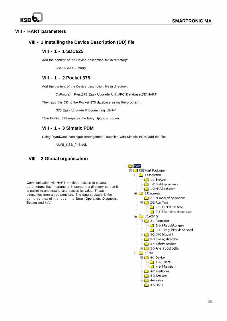
Communication via HART provides access to several
parameters. Each parameter is stored in a directory so that it
is easier to understand and access its value. These
directories form a tree structure. The data structure is the
same as that of the local interface (Operation, Diagnosis,
Setting and Info).
36
SMARTRONIC MA
The ”Main” directory is the source directory containing the entire data tree structure.
The ”Operation” directory contains the values of the signals specific to positioning:
- Values of the main signals: System
- Theoretical state of the end stop sensors
- Position setpoint if the product is operating in HART mode: HART setpoint
The ”Diagnosis” directory contains the values specific to device diagnosis:
- Number of operations (opening/closing cycle)
- Total run time since installation
- Run time since last reset
The ”Settings” directory contains the value specific to product configuration:
- Adjustment of position regulation performance: Regulator
- Input current/setpoint correlation: O/C fct point
- Closing direction
- Safety position on loss of electrical supply
- Analogue input/output calibration
The ”Info” directory contains the usual information concerning:
- The device
- The positioner
- The actuator
- The valve
- The typical HART data
VIII - 3 Details of the file tree structure content
VIII - 3 - 1 ”KSB Hart Positioner” directory
Operation (cf. VIII - 3 - 2)
Diagnosis (cf. VIII - 3 - 3)
Settings (cf. VIII - 3 - 4)
Info (cf. VIII - 3 - 5)
VIII - 3 - 2 ”Operation” directory
VIII - 3 - 2 - 1 ”System” directory
Loop current: value of the 4-20 mA signal in input in mA (read only)
-- Position value (PV): Valve position as a % (read only)
-- Setpoint (SV): Position setpoint as a % (read only)
-- Deviation (TV): Error between the setpoint and the true valve position as a % (read only)
-- Output current (QV): Theoretical current present in the current output loop in mA (read only)
-- Control mode: Product operating mode: Auto, manual or HART (read only)
VIII - 3 - 2 - ”Endstop sensors” directory
-- Open Endstop: Theoretical state of the ”opening” end stop sensor (read only):
0: not in open position
1: in open position
-- Close Endstop: Theoretical state of the ”closing” end stop sensor (read only):
0: not in close position
1 : in close position
37
SMARTRONIC MA
VIII - 3 - 2 - 3 ”HART setpoint” directory
-- HART position Setpoint: Position setpoint as a % if product is operating in HART mode (read/write)
VIII - 3 - 3 ”Diagnosis” directory
VIII - 3 - 3 - 1 ”Number of operations” directory
-- Number of operation: Number of opening/closing cycles (read only, but can be reset)
VIII - 3 - 3 - 2 ”Run time” directory
Total run time (read only)
-- Days: Number of days operation since the 1st time the product was started
-- Hours: Number of hours operation since the 1st time the product was started
-- Minutes: Number of minutes operation since the 1st time the product was started
Run time since reset (read only)
-- Days: Number of days operation since the last reset
-- Hours: Number of hours operation since the last reset
-- Minutes: Number of minutes operation since the last reset
VIII - 3 - 4 ”Settings” directory
VIII - 3 - 4 - 1 ”Regulator” directory
-- Autocalibration status
Autocalibration procedure step (read only:
- End - Standby
- Working ...: Auto-calibration in progress.
-- Auto-calibration
Function to start the autocalibration procedure (write only).
HART communication is no longer possible during autocalibration.
-- Positioner status :
Positioner calibration status (read only)
- Run
- Calibration Run
- Calibration Done
- Calibration Fail
- Calibration change rotation direction
- Calibration Start
- Calibration Pause
- Calibration Stop
- Calibration Abort
- Calibration Fail: hardware
- Calibration Fail: regulator
38
SMARTRONIC MA
Regulator gain (read/write)
-- Opening gain: (see §VII - 5 - 1 - 3)
-- Closing gain: (see §VII - 5 - 1 - 3)
Regulator dead band (read/write)
-- Opening dead band as a % (see §VII - 5 - 1 - 2)
-- Closing dead band as a % (see §VII - 5 - 1 - 2)
VIII - 3 - 4 - 2 ”O/C fct point” directory
Used to define the relation between the input current and the position setpoint.
(For further details, see VII - 5 - 2)
-- Current No. 1: Current value associated with position 1 (read/write)
-- Position No. 1: Current value associated with current 1 (read/write)
-- Current No. 2: Current value associated with position 2 (read/write)
-- Position No. 2: Current value associated with current 2 (read/write)
VIII - 3 - 4 - 3 ”Closing direction” directory
-- Closing direction: Defines the valve closing direction. (read/write) (see §VII - 5 - 3 )
VIII - 3 - 4 - 4 ”Safety position” directory
-- Safety position: Defines the valve safety position on loss of electrical supply (read/write)
Caution: Must comply with the plate type (A or B) and distributor used (see §IV - 3)
VIII - 3 - 4 - 5 ”Ana. In/Out calib.” directory In/out calib.”
Ana. Input calib. (read/write)
-- Start ana. In calib.: function used to calibrate the 4- 20 mA analogue input
Ana. ouput calib. (read/write)
-- Real out 4mA. : Real value of the 4- 20 mA output when variable ”Ana. Output
Control” is set to ”Send 4 mA output” (read/write).
-- Real out 20mA.: Real value of the 4- 20 mA output when variable ”Ana. Output
Control” is set to ”Send 20mA output” (read/write).
-- Ana. Output Control.: Variable used to control the 4- 20 mA analogue output
manually (read/write):
- End -- stanby : analogue output in automatic mode (image of valve
position)
- Send 4mA output: analogue output forced manually to low level
(close to 4 mA)
- Send 20 mA output: analogue output forced manually to high level
(close to 20 mA)
-- Start ana. out calib.: Function used to calibrate the 4- 20 mA analogue output
39
SMARTRONIC MA
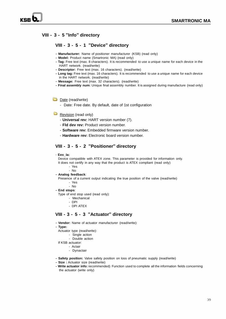
VIII - 3 - 5 ”Info” directory
VIII - 3 - 5 - 1 ”Device” directory
-- Manufacturer: Name of positioner manufacturer (KSB) (read only)
-- Model: Product name (Smartronic MA) (read only)
-- Tag: Free text (max. 8 characters). It is recommended to use a unique name for each device in the
HART network. (read/write)
-- Descriptor: Free text (max. 16 characters). (read/write)
-- Long tag: Free text (max. 16 characters). It is recommended to use a unique name for each device
in the HART network. (read/write)
-- Message: Free text (max. 32 characters). (read/write)
-- Final assembly num: Unique final assembly number. It is assigned during manufacture (read only)
Date (read/write)
- Date: Free date. By default, date of 1st configuration
Revision (read only)
- Universal rev: HART version number (7).
- Fld dev rev: Product version number.
- Software rev: Embedded firmware version number.
- Hardware rev: Electronic board version number.
VIII - 3 - 5 - 2 ”Positioner” directory
- Eex_Ia:
Device compatible with ATEX zone. This parameter is provided for information only.
It does not certify in any way that the product is ATEX compliant (read only)
- Yes
- No
-- Analog feedback:
Presence of a current output indicating the true position of the valve (read/write)
- Yes
- No
-- End stops:
Type of end stop used (read only):
- Mechanical
- DPI
- DPI ATEX
VIII - 3 - 5 - 3 ”Actuator” directory
-- Vendor: Name of actuator manufacturer (read/write):
-- Type:
Actuator type (read/write):
- Single action
- Double action
If KSB actuator:
- Actair
- Dynactair
-- Safety position: Valve safety position on loss of pneumatic supply (read/write)
-- Size : Actuator size (read/write)
-- Write actuator info: recommended) Function used to complete all the information fields concerning
the actuator (write only)

40
SMARTRONIC MA
VIII - 3 - 5 - 4 ”Valve” directory
-- Vendor: Name of valve manufacturer (read/write)
-- Type: Valve type (read/write)
-- Size: Valve size (read/write)
-- Write valve info: (recommended) Function used to complete all the information fields concerning
the valve and save them (write only)
VIII - 3 - 5 - 5 ”HART” directory
-- Poll addr : Network polling address (read/write)
IX - Conformity
Compliant with the ATEX directive.
41
SMARTRONIC MA
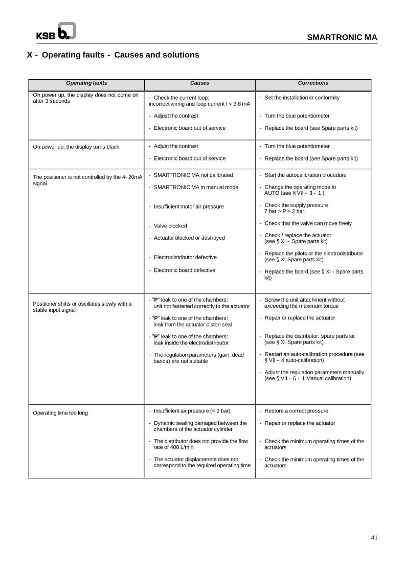
X - Operating faults - Causes and solutions
Operating faults Causes Corrections
On power up, the display does not come on after 3 seconds
- Check the current loop: incorrect wiring and loop current I < 3.8 mA - Adjust the contrast - Electronic board out of service
- Set the installation in conformity - Turn the blue potentiometer - Replace the board (see Spare parts kit)
On power up, the display turns black - Adjust the contrast - Electronic board out of service
- Turn the blue potentiometer - Replace the board (see Spare parts kit)
The positioner is not controlled by the 4- 20mA signal
- SMARTRONIC MA not calibrated - SMARTRONIC MA in manual mode
- Insufficient motor air pressure
- Valve blocked - Actuator blocked or destroyed
- Electrodistributor defective
- Electronic board defective
- Start the autocalibration procedure
- Change the operating mode to AUTO (see § VII - 3 - 1 )
- Check the supply pressure
7 bar > P > 2 bar - Check that the valve can move freely - Check / replace the actuator
(see § XI - Spare parts kit) - Replace the pilots or the electrodistributor
(see § XI Spare parts kit) - Replace the board (see § XI - Spare parts
kit)
Positioner shifts or oscillates slowly with a stable input signal
- ”P” leak to one of the chambers: unit not fastened correctly to the actuator
- ”P” leak to one of the chambers:
leak from the actuator piston seal - ”P” leak to one of the chambers:
leak inside the electrodistributor - The regulation parameters (gain, dead
bands) are not suitable
- Screw the unit attachment without exceeding the maximum torque
- Repair or replace the actuator - Replace the distributor: spare parts kit
(see § XI Spare parts kit) - Restart an auto-calibration procedure (see
§ VII - 4 auto-calibration) - Adjust the regulation parameters manually
(see § VII - 6 - 1 Manual calibration)
Operating time too long - Insufficient air pressure (< 2 bar)
- Dynamic sealing damaged between the
chambers of the actuator cylinder - The distributor does not provide the flow
rate of 400 L/min - The actuator displacement does not
correspond to the required operating time
- Restore a correct pressure - Repair or replace the actuator - Check the minimum operating times of the
actuators - Check the minimum operating times of the
actuators
42
SMARTRONIC MA
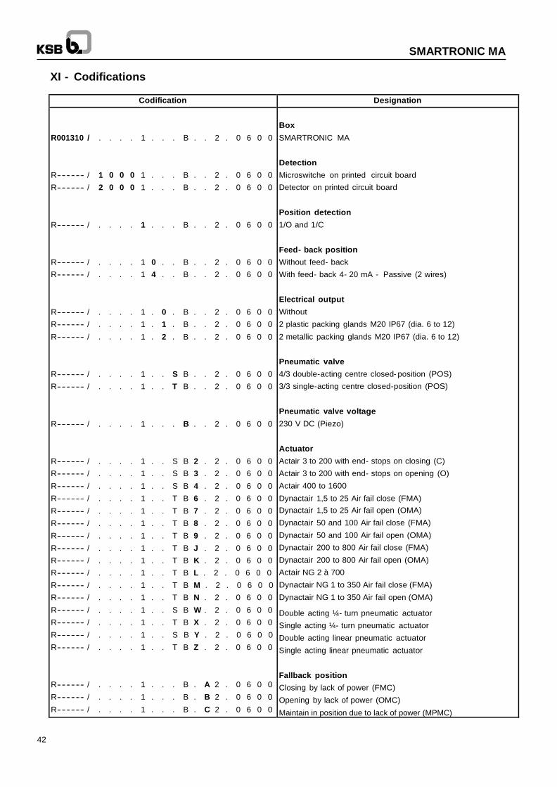
XI - Codifications
Codification Designation
R001310 / . . . . 1 . . . B . . 2 . 0 6 0 0
R-- -- -- -- -- -- / 1 0 0 0 1 . . . B . . 2 . 0 6 0 0
R-- -- -- -- -- -- / 2 0 0 0 1 . . . B . . 2 . 0 6 0 0
R-- -- -- -- -- -- / . . . . 1 . . . B . . 2 . 0 6 0 0
R-- -- -- -- -- -- / . . . . 1 0 . . B . . 2 . 0 6 0 0
R-- -- -- -- -- -- / . . . . 1 4 . . B . . 2 . 0 6 0 0
R-- -- -- -- -- -- / . . . . 1 . 0 . B . . 2 . 0 6 0 0
R-- -- -- -- -- -- / . . . . 1 . 1 . B . . 2 . 0 6 0 0
R-- -- -- -- -- -- / . . . . 1 . 2 . B . . 2 . 0 6 0 0
R-- -- -- -- -- -- / . . . . 1 . . S B . . 2 . 0 6 0 0
R-- -- -- -- -- -- / . . . . 1 . . T B . . 2 . 0 6 0 0 R-- -- -- -- -- -- / . . . . 1 . . . B . . 2 . 0 6 0 0 R-- -- -- -- -- -- / . . . . 1 . . S B 2 . 2 . 0 6 0 0
R-- -- -- -- -- -- / . . . . 1 . . S B 3 . 2 . 0 6 0 0
R-- -- -- -- -- -- / . . . . 1 . . S B 4 . 2 . 0 6 0 0
R-- -- -- -- -- -- / . . . . 1 . . T B 6 . 2 . 0 6 0 0
R-- -- -- -- -- -- / . . . . 1 . . T B 7 . 2 . 0 6 0 0
R-- -- -- -- -- -- / . . . . 1 . . T B 8 . 2 . 0 6 0 0
R-- -- -- -- -- -- / . . . . 1 . . T B 9 . 2 . 0 6 0 0
R-- -- -- -- -- -- / . . . . 1 . . T B J . 2 . 0 6 0 0
R-- -- -- -- -- -- / . . . . 1 . . T B K . 2 . 0 6 0 0
R-- -- -- -- -- -- / . . . . 1 . . T B L . 2 . 0 6 0 0
R-- -- -- -- -- -- / . . . . 1 . . T B M . 2 . 0 6 0 0
R-- -- -- -- -- -- / . . . . 1 . . T B N . 2 . 0 6 0 0
R-- -- -- -- -- -- / . . . . 1 . . S B W . 2 . 0 6 0 0
R-- -- -- -- -- -- / . . . . 1 . . T B X . 2 . 0 6 0 0
R-- -- -- -- -- -- / . . . . 1 . . S B Y . 2 . 0 6 0 0
R-- -- -- -- -- -- / . . . . 1 . . T B Z . 2 . 0 6 0 0 R-- -- -- -- -- -- / . . . . 1 . . . B . A 2 . 0 6 0 0
R-- -- -- -- -- -- / . . . . 1 . . . B . B 2 . 0 6 0 0
R-- -- -- -- -- -- / . . . . 1 . . . B . C 2 . 0 6 0 0
Box
SMARTRONIC MA
Detection
Microswitche on printed circuit board
Detector on printed circuit board
Position detection
1/O and 1/C
Feed- back position
Without feed- back
With feed- back 4- 20 mA - Passive (2 wires)
Electrical output
Without
2 plastic packing glands M20 IP67 (dia. 6 to 12)
2 metallic packing glands M20 IP67 (dia. 6 to 12)
Pneumatic valve
4/3 double-acting centre closed- position (POS)
3/3 single-acting centre closed-position (POS)
Pneumatic valve voltage
230 V DC (Piezo)
Actuator
Actair 3 to 200 with end- stops on closing (C)
Actair 3 to 200 with end- stops on opening (O)
Actair 400 to 1600
Dynactair 1,5 to 25 Air fail close (FMA)
Dynactair 1,5 to 25 Air fail open (OMA)
Dynactair 50 and 100 Air fail close (FMA)
Dynactair 50 and 100 Air fail open (OMA)
Dynactair 200 to 800 Air fail close (FMA)
Dynactair 200 to 800 Air fail open (OMA)
Actair NG 2 à 700
Dynactair NG 1 to 350 Air fail close (FMA)
Dynactair NG 1 to 350 Air fail open (OMA)
Double acting ¼- turn pneumatic actuator
Single acting ¼- turn pneumatic actuator
Double acting linear pneumatic actuator
Single acting linear pneumatic actuator
Fallback position
Closing by lack of power (FMC)
Opening by lack of power (OMC)
Maintain in position due to lack of power (MPMC)
43
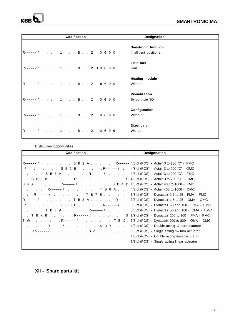
SMARTRONIC MA
Codification Designation
R-- -- -- -- -- -- / . . . . 1 . . . B . . 2 . 0 6 0 0
R-- -- -- -- -- -- / . . . . 1 . . . B . . 2 D 0 6 0 0
R-- -- -- -- -- -- / . . . . 1 . . . B . . 2 . 0 6 0 0
R-- -- -- -- -- -- / . . . . 1 . . . B . . 2 . 0 6 0 0
R-- -- -- -- -- -- / . . . . 1 . . . B . . 2 . 0 6 0 0 R-- -- -- -- -- -- / . . . . 1 . . . B . . 2 . 0 6 0 0
Smartronic function
Intelligent positioner
Field bus
Hart
Heating module
Without
Visualization
By porthole 3D
Configuration
Without
Diagnosis
Without
Distribution opportunities
Codification Designnation
R-- -- -- -- -- -- / . . . . . . . S B 2 A . . . . . . R-- -- -- -- -- -
- / . . . . . . . S B 2 B . . . . . . R-- -- -- -- -- -- / . .
. . . . . S B 3 A . . . . . . R-- -- -- -- -- -- / . . . . .
. . S B 3 B . . . . . . R-- -- -- -- -- -- / . . . . . . . S
B 4 A . . . . . . R-- -- -- -- -- -- / . . . . . . . S B 4 B
. . . . . . R-- -- -- -- -- -- / . . . . . . . T B 6 A . . .
. . . R-- -- -- -- -- -- / . . . . . . . T B 7 B . . . . . .
R-- -- -- -- -- -- / . . . . . . . T B 8 A . . . . . . R-- -- -- -- -- -
- / . . . . . . . T B 9 B . . . . . . R-- -- -- -- -- -- / . .
. . . . . T B J A . . . . . . R-- -- -- -- -- -- / . . . . .
. . T B K B . . . . . . R-- -- -- -- -- -- / . . . . . . . S
B W . . . . . . . R-- -- -- -- -- -- / . . . . . . . T B X .
. . . . . . R-- -- -- -- -- -- / . . . . . . . S B Y . . . .
. . . R-- -- -- -- -- -- / . . . . . . . T B Z . . . . . . .
4/3 cf (POS) - Actair 3 to 200 “C” - FMC
4/3 cf (POS) - Actair 3 to 200 “C” - OMC
4/3 cf (POS) - Actair 3 to 200 “O” - FMC
4/3 cf (POS) - Actair 3 to 200 “O” - OMC
4/3 cf (POS) - Actair 400 to 1600 - FMC
4/3 cf (POS) - Actair 400 to 1600 - OMC
3/3 cf (POS) - Dynactair 1,5 to 25 - FMA - FMC
3/3 cf (POS) - Dynactair 1,5 to 25 - OMA - OMC
3/3 cf (POS) - Dynactair 50 and 100 - FMA - FMC
3/3 cf (POS) - Dynactair 50 and 100 - OMA - OMC
3/3 cf (POS) - Dynactair 200 to 800 - FMA - FMC
3/3 cf (POS) - Dynactair 200 to 800 - OMA - OMC
4/3 cf (POS) - Double acting ¼- turn actuator
3/3 cf (POS) - Single acting ¼- turn actuator
4/3 cf (POS) - Double acting linear actuator
3/3 cf (POS) - Single acting linear actuator
XII - Spare parts kit

SMARTRONIC MA
42
09.0
1.2
018
This
leafle
t is
not co
ntr
actu
al
and m
ay b
e a
mende
d w
ithout
no
tice
. 8
52
0.8
04
1/7
-EN
KSB S.A.S
4, allée des Barbanniers 92635 Gennevilliers Cedex (France)
Tél. : +33 (1) 41 47 75 00
www.ksb.com