SmartPrep Automated SPE Cartridge Extractor II Module on your purchase of the SmartPrep Extractor II...
158
SmartPrep ® Automated SPE Cartridge Extractor II Module Users Guide
Transcript of SmartPrep Automated SPE Cartridge Extractor II Module on your purchase of the SmartPrep Extractor II...

SmartPrep® Automated SPE Cartridge Extractor II Module
Users Guide

SMARTPREP MODULE
ii
16 Northwestern Drive, Salem, NH 03079
Telephone: (603) 893-3663
Toll-Free: (800) 997-2997 USA Only
Website: www.horizontechinc.com
Copyright © 2016 by Horizon Technology, Inc.
All rights reserved. Horizon Technology, Inc. reserves the right to change the infor-mation in this document without notice. No part of this work may be processed, re-produced, or transmitted in any form or by any means, electronic or mechanical,
including photocopying and recording, or by any information storage or retrieval sys-tem, except as may be expressly permitted in writing by Horizon Technology, Inc.
SmartPrep and SPE-DEX are registered trademarks of Horizon Technology, Inc. Windows is a registered trademark of Microsoft Corporation.
All other product names herein are used for identification purposes only and are rec-ognized as properties (including trademarks, registered trademarks, and referenced
copyrighted materials) of their respective holders.
P/N: 29-2800-01 Rev. F
(February 2017)

iii
Table of Contents
Preface ........................................................................................................................................... vi Your SmartPrep® Extractor II Module ..................................................................................................... vi Manual Audience and Intent ................................................................................................................... vi
Conventions ................................................................................................................................... vii Table of Symbols ........................................................................................................................... vii Serial Number Label ...................................................................................................................... vii
Technical Support .................................................................................................................................. viii Introduction and Safety .......................................................................................................... 1 1
1.1 System Overview ............................................................................................................................ 1 1.2 SmartPrep Extractor II Module ........................................................................................................ 2 1.3 PC Controller .................................................................................................................................. 2 1.4 Software Overview .......................................................................................................................... 3 1.5 Product Safety Notice and Certification........................................................................................... 3
1.5.1 General Safety .................................................................................................................. 3 1.5.2 Chemical Safety ................................................................................................................ 4
Theory of Operation ................................................................................................................ 6 22.1 Automated Cartridge Use ................................................................................................................ 6 2.2 The Extraction Cycle—A Detailed Look .......................................................................................... 6
Step 1: Condition the SPE cartridge with reagents ....................................................................... 6 Step 2: Introduce the Sample to the SPE Cartridge ...................................................................... 7 Step 3: Wash the SPE cartridge with Reagents ............................................................................ 7 Step 4: Dry the SPE Cartridge with Nitrogen Gas ......................................................................... 7 Step 5: Elute the SPE Cartridge with the Eluting Reagents .......................................................... 7
2.3 SPE Cartridge Operations and the SmartPrep Module ................................................................... 8 Part I: Getting Started ................................................................................................................. 10
Site Preparation and Unpacking .......................................................................................... 11 33.1 Preparing the Site ......................................................................................................................... 11 3.2 Unpacking the SmartPrep Module ................................................................................................ 13
SmartPrep Hardware Overview............................................................................................ 19 44.1 Front and Side Features ............................................................................................................... 19 4.2 Back Panel Features ..................................................................................................................... 21
Installing the SmartPrep Module ......................................................................................... 24 55.1 Installing a SmartPrep Module ...................................................................................................... 24 5.2 Installing Multiple SmartPrep Modules .......................................................................................... 26 5.3 Installing the SmartPrep Module Software .................................................................................... 27 5.4 Configuring the System for Operation ........................................................................................... 31 5.5 System Configuration—Using the Set Up Module Option ............................................................. 31
5.5.1 Configure Communication Ports ..................................................................................... 32 5.5.2 Waste Ports .................................................................................................................... 33 5.5.3 Module ............................................................................................................................ 33 5.5.4 Reagents ........................................................................................................................ 33 5.5.5 Plunger Size ................................................................................................................... 35 5.5.6 Bottle Rinse Configuration .............................................................................................. 35

iv
5.5.7 Tubing Volume ................................................................................................................ 35 5.5.8 Verifying the Optimal Tubing Volume Values.................................................................. 36 Visual Verification ......................................................................................................................... 36 Gravimetric Verification ................................................................................................................. 38 5.5.9 Edit Reagent Names ....................................................................................................... 40 5.5.10 Edit Cartridge Names ..................................................................................................... 41 5.5.11 Edit Waste Port Names .................................................................................................. 42 5.5.12 Reagent and Sample Valves .......................................................................................... 42 5.5.13 Calibration Factors .......................................................................................................... 43 5.5.14 Utilities ............................................................................................................................ 45
Part II: SmartPrep Software and Operation.............................................................................. 48
Software Overview ................................................................................................................ 49 66.1 SmartPrep Control Window ........................................................................................................... 50 6.2 Module Programming Panel .......................................................................................................... 51 6.3 SmartPrep Extractor Error Codes & Definitions ............................................................................ 53 6.4 Method Assignment Panel ............................................................................................................ 54 6.5 System Status Panel ..................................................................................................................... 55 6.6 Collection Tubes Panel ................................................................................................................. 55 6.7 Fluid Volume Status Panel ............................................................................................................ 56 6.8 System Controls Panel.................................................................................................................. 56
Advanced Options ................................................................................................................ 57 77.1 Advanced Options (Programming) ................................................................................................ 57 7.2 Setting a Password ....................................................................................................................... 58 7.3 Set Up Procedure-Using the Compose Method Option ................................................................ 58
7.3.1 Method Name ................................................................................................................. 58 7.3.2 Cartridge ......................................................................................................................... 59 7.3.3 Cartridge Size ................................................................................................................. 59 7.3.4 Method Description ......................................................................................................... 59 7.3.5 Condition Cartridge ......................................................................................................... 60 7.3.6 Load Large Volume Sample ........................................................................................... 62 7.3.7 Load Small Volume Sample ........................................................................................... 63 7.3.8 Load Sample for Cleanup ............................................................................................... 66 7.3.9 Wash Cartridge ............................................................................................................... 69 7.3.10 Elute Cartridge ................................................................................................................ 70 7.3.11 Sample Bottle Rinse ....................................................................................................... 71 7.3.12 Sample Bottle Elute ........................................................................................................ 72 7.3.13 Soak ............................................................................................................................... 73 7.3.14 Time Delay Start ............................................................................................................. 73 7.3.15 Pause with Message ....................................................................................................... 73 7.3.16 N2 Purge Timer .............................................................................................................. 74 7.3.17 Add to Mixing Chamber .................................................................................................. 74 7.3.18 Mix Chamber .................................................................................................................. 75 7.3.19 Prime Reagent Lines ...................................................................................................... 76 7.3.20 Clean System Tubing ..................................................................................................... 76 7.3.21 Clean Sample Lines ........................................................................................................ 80 7.3.22 Clean Plunger ................................................................................................................. 81
7.4 View and Print Reports—Using the Reports Option ...................................................................... 82 7.5 Using Manual Control.................................................................................................................... 84 7.6 Advanced Programming Features ................................................................................................ 84

v
7.6.1 How to Determine the TV Value ..................................................................................... 84 7.6.2 How to Estimate Sample Volume Calculation Variables ................................................. 84 7.6.3 How to use the SmartPrep Module without Being Connected to the PC ........................ 87 7.6.4 How to Use the Sample Set Up Sequence Feature ........................................................ 88
Composing Methods ........................................................................................................... 90 88.1 Overview of Composing a Sample Method ................................................................................... 90 8.2 Composing a Sample Method, Part 1: Configuring the Module .................................................... 90 8.3 Composing a Sample Method, Part 2: Composing a Prime Reagent Lines Method .................... 92 8.4 Composing a Sample Method, Part 3: Composing a Procedure ................................................... 95 8.5 Preparing to Run Methods .......................................................................................................... 103
Summary of Normal Operations and Recommendations ............................................... 109 99.1 Best Practices ............................................................................................................................. 109
9.1.1 General ......................................................................................................................... 109 9.1.2 Proper Acid and Base Usage........................................................................................ 109 9.1.3 Pre Run Methods .......................................................................................................... 109 9.1.4 After Sample Cleanup Methods .................................................................................... 110
9.2 Daily Startup: Powering Up the SmartPrep Module .................................................................... 111 9.3 Daily Startup: Preparing the Module ........................................................................................... 112 9.4 Priming the Reagent Lines .......................................................................................................... 112 9.5 Cleaning the Sample Lines ......................................................................................................... 112 9.6 Preventing Carryover .................................................................................................................. 113 9.7 Daily Shut Down Procedure ........................................................................................................ 113 9.8 Extended Shut Down Procedure ................................................................................................. 114
Manual Control Operations ................................................................................................ 117 10
Part III: Routine Operations and Service ................................................................................ 122 Routine Operations ............................................................................................................. 123 11
11.1 Normal Wear Components .......................................................................................................... 123 11.1.1 Plunger O-ring Seals .................................................................................................... 123 11.1.2 Syringe Pump (Plunger/Glass/Plug) ............................................................................. 123 11.1.3 12 Port Valves .............................................................................................................. 123
11.2 Changing the Plunger Assembly ................................................................................................. 124 11.3 Replacing the O-Ring on the Plunger Assembly ......................................................................... 124 11.4 Homing the Syringe Plunger ....................................................................................................... 125 11.5 Adjusting the Carousel Offset Position ........................................................................................ 126 11.6 Adjusting the Syringe Liquid Sensor Position .............................................................................. 126
Service .................................................................................................................................. 128 1212.1 Taking a Module Off-Line ............................................................................................................ 128
Part IV: Appendices .................................................................................................................. 131
A Technical Description ......................................................................................................... 132 Equipment Specifications ..................................................................................................................... 132 Accessories and Kits ............................................................................................................................ 132
B Plumbing Diagrams ............................................................................................................ 134 C SmartPrep Extractor Accessories ..................................................................................... 136
D Editing a V1.0.0.18 Method to run in V2.0 ......................................................................... 142
E Factory Supplied Green Food Coloring Methods ............................................................ 146
F Limited Warranty ................................................................................................................. 149

vi
Preface
Your SmartPrep® Extractor II Module Congratulations on your purchase of the SmartPrep Extractor II Module, the latest generation of automated cartridge Solid Phase Extraction (SPE) systems from Horizon Technology. The SmartPrep Module offers a powerful blend of intelligence and ease of use to make automated SPE simple and affordable for method developers and sample prep laboratories taking the first step to automation. We are confident the SmartPrep Module will be a welcome addition to your laboratory.
FCC (USA) The SmartPrep Module has been tested and found to comply with the limits for a Class A device, pursuant to Part 15 of the FCC Rules. These limits are designed to provide reasonable protection against harmful interferences when the equipment is operated in a commercial environment. This equipment generates, uses, and can radiate radio frequency energy and, if not installed and used in accordance with the user’s manual, may cause harmful interference to radio communications. Operation of this equipment in a residential area is likely to cause harmful interference in which case the user will be required to correct the interference at his/her own expense.
Product Safety The SmartPrep Module is designed with operator safety in mind. However, the product use is at the discretion and risk of the operator or laboratory supervisor/manager. Use the product as de-scribed in this manual. Refer to Section 1.5, Product Safety Notice and Certification.
Statement of Proper Use The SmartPrep Module is a modular workstation, designed specifically for 1, 3, and 6 mL Solid Phase Extraction (SPE) cartridges from most manufacturers. The SmartPrep Module allows rapid development of reliable automated SPE procedures from current manual processes.
WARNING To reduce the risk of electrical shock, do not disassemble the module. There are no serviceable parts inside. Refer repairs to qualified service personnel.
Manual Audience and Intent This manual, which is intended for all SmartPrep Module users in the laboratory environment, provides the information needed to operate and maintain the SmartPrep Module. The information may contain typographical errors or technical inaccuracies and is subject to change without no-tice. Modifications or enhancements may also be made to the product at any time. For the most current information, consult the Horizon website at www.horizontechinc.com.

Manual Audience and Intent
vii
Conventions The following texts are examples of conventions used in this manual.
Example Description
Declaration of Conformity Italicized text indicates document and section titles as well as special notes.
Setup.Exe Courier type indicates a program file name. OK/Save as Bold type indicates a button or information displayed on the
screen.
WARNING Symbols to the left of a NOTE or WARNING indicate the type of danger that could be present, such as high voltage, fire, explosion, etc. See the Table of Symbols, below, for details.
Table of Symbols The following symbols point out important information and alert you to potential hazards.
Symbol Type Description
Warning A potentially hazardous situation, which if not avoided could result in
death or serious injury.
Note A safety note for operation or additional explanation. This informs and
guides you in safe practices to avoid injury and is intended to cover gen-eral safety requirements for a laboratory. Each laboratory is responsible for implementing and communicating its unique safety requirements and program to all workers.
Caution A caution concerning operations that may cause a hand pinch. Where indicated, keep hands clear and refer to the manual.
Caution A caution concerning potential eye injury. Eye protection in the form of
safety glasses or goggles is highly recommended when operating the SmartPrep Module and any chemical processing. If reagents, liquids, or vapors come into contact with the eyes, follow the appropriate first aid procedures set forth in the laboratory’s safety manual.
Caution A caution concerning the potential of a fire.
Caution A caution to wear protective gloves when handling harmful reagents.
Serial Number Label The following is a sample of the serial number label located on the back of the SmartPrep Mod-ule.

Preface
viii
Technical Support Visit the Horizon website for technical information in addition to that provided in this manual: www.horizontechinc.com. If you have questions about the SmartPrep Module that are not fully addressed in this manual or our website, please contact the Horizon Technology Technical Cus-tomer Support Center:
Phone: (603) 893-3663 Fax: (603) 893-4994 E-mail: [email protected]
Customer Support Center hours are Monday through Friday, 8:00 a.m. to 5:00 p.m. EST. The Center provides expert technical support including troubleshooting, repair instructions, service and installation scheduling, and replacement part information.
Notes:

1
Introduction and Safety 1
1.1 System Overview The SmartPrep Module is the latest generation of automated cartridge Solid Phase Extraction (SPE) systems from Horizon Technology.
Figure 1-1. SmartPrep Module and Multiple Modules, used Together
The SmartPrep Extractor II Module is a modular workstation de-signed for 1, 3, and 6 mL tabbed and tabless SPE cartridges. Mod-ules configured can handle up to 12 cartridges, while future enhancements may handle up to 20 cartridges. Using a PC-based ap-proach, software provides a graphical user interface, allowing rapid development of reliable automated SPE procedures from current manual processes. The PC Controller handles up to 8 modules, all of which run independently of each other. This enhanced capability in-creases the flexibility of any laboratory to match capacity to work-load.
All reagents, methods, and control parameters are visually displayed to provide convenient and easy programming and operation. An interactive Touch Screen display on each module informs the operator of the current status of each module, and allows easy interaction with the module.
The SmartPrep Module is specifically designed to handle the extraction of organic analytes from liquid samples, such as water samples, food extracts, transformer oil and others. This easy-to-use SPE system sets new standards for both ease of sample extraction and reproducibility of results.
Figure 1-2. 1, 3 and 6-mL SPE Cartridges

1: Introduction and Safety
2
The SmartPrep Module allows testing facilities to:
• Provide more reliable results by improving reproducibility • Reduce attention required while maintaining quality • Process samples unattended, allowing better use of personnel time. • Improve operator safety by reducing exposure to reagents. • Segregate waste reagents according to chemical requirements; separate chlorinated from non-
chlorinated, etc.
The system consists of two main components:
1. SmartPrep Extractor II Module 2. PC Controller
1.2 SmartPrep Extractor II Module The SmartPrep Extractor II module is designed to use volumes from 1mL to 4 liters with the 1, 3, or 6-mL cartridge of your choice. The cartridges for use can be tabbed or tabless. Buffer-filled Immunoaffinity cartridges can also be accommodated with a unique piercing plunger.
The SmartPrep Module is designed for liquid samples such as drinking water, wastewater, groundwater samples, food extracts, transformer oils or other samples that require cleanup or concentration of the analytes. Each module can utilize up to 8 reagents and run multiple analyti-cal methods sequentially. If more than one module is used, multiple samples can be processed simultaneously, which will significantly increase sample throughput. If samples with particulate matter or debris are to be processed, it is recommended to use the in-line 3.1 micron membrane filter.
Each SmartPrep Module allows 12 SPE cartridges to be loaded, so 12 samples can be processed, sequentially. If desired, different analytical methods can be run for each sample. This versatility is ideal for method development. The SmartPrep Module automatically:
• introduces all reagents, • introduces the samples, • monitors all liquids to ensure liquids are flowing properly, • rinses the sample bottles with reagents, if desired and • extracts the analytes from the SPE cartridges.
The modules are self-contained, allowing bench top operation.
For maximum capability, up to 8 modules can be interfaced and programmed from a single PC Controller (described below). With 8 modules, a total of 96 samples can be processed unattended, as each individual module can process 12 samples.
The SmartPrep Extractor II module uses FEP tubing, which is chemically resistant, flexible and consistent. FEP tubing is the preferred tubing if samples are to be analyzed for PFC’s (perfluoro-nated compounds), where the use of PTFE tubing would contribute to unacceptably high back-ground values.
1.3 PC Controller The PC Controller software comes preprogrammed with a selection of methods to get you started. These preprogrammed methods can be used as is, or can be modified to better suit the user's indi-vidual needs.

1.4: Software Overview
3
In addition, new methods can be easily created and modified. Creating custom methods allows optimization of the operating parameters to meet your own unique requirements and/or to take advantage of new SPE cartridge technologies as they become available.
The software on the PC controller can be password protected to ensure unauthorized changes to the method are not entered. Additionally, the PC controller works with the touch screen on the module itself. A method can be downloaded to the module and run without the PC, making the system more secure and simpler for a technician to operate.
The PC Controller provides the programming for up to 8 SmartPrep Modules. Each module can be operated simultaneously or independently from other modules. Each module can be pro-grammed to run the same method, or they can be individually programmed to run any combina-tion of different methods. To add more modules to a system, simply plug a new module into a USB hub port and power the module on and select the proper communication port. The PC Con-troller software will recognize the module and allow the new module to be used.
1.4 Software Overview The SmartPrep Module software includes the following distinct features:
• Employs Windows-based software with icons to readily relay the module status. • Allows up to 12 different analytical methods to be run on a single module. • Allows for up to 8 SmartPrep Modules to be run simultaneously. • Allows methods to be run as pre-run and/or post-run operations so modules can be automati-
cally cleaned and prepped before running actual samples, or cleaned up at the end of a run se-quence.
• Generates and stores reports for all runs, for later retrieval by the operator. • Automatically calculates and displays the total volume of reagents required and the total vol-
ume of waste to be generated based on the methods and the total number of samples to be run. • Downloads the methods and control directly to each SmartPrep Module so methods can be
operated in a secure fashion.
1.5 Product Safety Notice and Certification 1.5.1 General Safety
• Eye protection in the form of safety glasses or goggles is highly recommended when op-erating the SmartPrep Module or any chemical processing. If reagents, liquids, or vapors come into contact with the eyes, follow the appropriate first aid procedures set forth in the laboratory’s safety manual.
• Lab coats should be provided for protection. They should be worn at all times when op-erating the SmartPrep Module.
• Protection of the hands is essential when working with reagents or any hazardous materi-al. Wear gloves selected on the basis of the hazard. If reagents or other chemicals come into contact with the skin, follow the appropriate first aid procedures set forth in the la-boratory’s safety manual.
• The SmartPrep Modules are designed for bench top or fume hood operation. If installed on a bench top, the reagent bottles could be placed under a vapor vent exhaust fan. The end of the exhaust hose should be ducted into a local exhaust device to avoid the dis-charge of potentially toxic vapors and fumes into the laboratory atmosphere. The equip-ment must be set up and operated in a well-ventilated area.

1: Introduction and Safety
4
• Care must be taken when the SmartPrep is in operation, to ensure that your hand is not near the SPE cartridge plunger, when the plunger is moving down into the SPE cartridge. The plunger motor has significant torque and could pinch your hand or finger.
• Do not work with volatile reagents without adequate ventilation from chemical fume hoods or other protective devices.
• Any suitable glass container can be used to contain the reagents. However, it is preferable to use a glass bottle, such that a small hole can be drilled through the cap, allowing the reagent sip line to be inserted through the hole. This will minimize the amount of reagent vapor that can escape in the atmosphere. Identify all reagents with suitable labels.
• The waste containers can be any suitable container and should be located below each SmartPrep Module for proper drainage. To aid with the disposal of waste reagents, each module is equipped with three independent waste port lines as well as a well as a single drain line dedicated to spill protection. This feature allows liquid waste to be directed to the waste container of choice. For example, all chlorinated waste can be kept separate from non-chlorinated waste. The ability to separate all waste will significantly reduce re-agent waste disposal costs.
• During the reagent rinse sequence, reagents are sprayed from the tip of the reagent rinse nozzle. Be sure the reagent rinse cap assembly is securely fastened to the sample bottle to be rinsed before initiating this rinse sequence.
• The PC Controller must be properly grounded for safe operation. Use only the power cord that is provided with a ground plug, and connect it to a grounded outlet.
• Do not use glass cartridges in the unit, they may break and cause a hazard.
• Disconnect the power cord before working on the module.
1.5.2 Chemical Safety • A Safety Data Sheet (SDS) is the source for chemical hazard information including basic
information on the manufacturer or distributor, identification of the chemical, the prod-uct’s hazardous ingredients, physical data, fire and explosion data, toxicity information, protection information, and more. The laboratory is responsible for having a SDS for every chemical or substance being used. It is also the laboratory’s responsibility to make the SDS available and accessible to all employees and to provide training in the safe han-dling of hazardous chemicals. The SDS can be obtained from the vendor.
• All hazardous reagents and chemicals must be disposed in accordance with appropriate Federal, state, and local regulations.
• The SmartPrep Modules allow the use of a pressurized gas source to pressurize the SPE cartridge and purge the cartridge of residual reagents, and to purge the reagent rinse lines when automatically rinsing the sample containers. The recommended source is a dry grade of nitrogen gas. If a gas cylinder is used, secure the gas cylinder to avoid tipping.
• The SmartPrep Modules use organic reagents that can pose inhalation, skin, and ingestion hazards with potential chronic health effects. Some of the reagents may also be flamma-ble, which could cause fire and/or explosion hazards. In general, chlorinated reagents are not flammable while non-chlorinated reagents are often flammable. However, chlorinated reagents do decompose when burned, resulting in high concentrations of toxic vapors. All reagents must be handled using appropriate personal protection equipment and in a properly operating fume hood to eliminate inhalation hazards. For handling and safety in-structions, refer to the Safety Data Sheet (SDS) for the specific chemical.

1.5: Product Safety Notice and Certification
5
Notes:

6
Theory of Operation 2
2.1 Automated Cartridge Use Solid phase adsorbents are used in many applications to either isolate the analytes of interest or isolate the interferences. It may be used effectively to concentrate analytes, allowing possible in-terferents to be washed away. SPE may be used to adsorb interfering compounds and the ana-lytes pass through the cartridge, cleaned up and ready for the analysis step.
2.2 The Extraction Cycle—A Detailed Look When using the SmartPrep Module, there are typically five major steps to extracting the analytes from a sample:
1. Condition the SPE cartridge with reagents 2. Introduce the sample to the SPE cartridge 3. Wash the SPE cartridge with reagents 4. Dry the SPE cartridge to remove residual water (using either nitrogen or air).
5. Elute the SPE cartridge with the eluting reagents
Step 1: Condition the SPE cartridge with reagents The following three steps of the Conditioning cycle are repeated with a series of reagents as re-quired by the analytical method. Though the reagent itself may change, the purpose of the follow-ing steps is identical from one analytical method to the next.
1. Conditioning reagent: The function of the conditioning reagent is to thoroughly remove any manufacturing impurities that might be present in the SPE packing material. Removing impuri-ties ensures that the SPE cartridge will not contribute any background contamination. The condi-tioning reagent may activate or makes the sorbent material more compatible with the sample composition and polarity. For example, methanol is typically used as the conditioning reagent for C18 packings. Once the packing is activated, the SPE cartridge must not be exposed to air until the completion of the sample cycle.
The syringe mechanism and associated 12-port valve are used to deliver conditioning reagents to the SPE cartridge. The SmartPrep Module can use a liquid sensor on the syringe mechanism to ensure that the reagent is properly delivered to the SPE cartridge. If the reagent is detected, the module continues with the process. However, if the reagent is not detected, the module stops and notifies the operator. This feature protects the integrity of the SPE cartridge and the sample.
2. Conditioning reagent soak time: Once the desired reagent has been delivered to the cartridge, it is necessary to allow the reagent to remain in the cartridge, so the reagent can extract any impu-rities out of the packing and send this reagent to waste. Since reagents can have different extrac-tion efficiencies, the software allows various soak times (from 0 seconds to 60 minutes) for each conditioning reagent introduced to the SPE cartridge.
3. Conditioning nitrogen drying time: If the conditioning reagent is being used to remove im-purities from the cartridge, nitrogen or vent can be used to remove the reagent from the packing. Since different reagents have different volatilities, the software allows various nitrogen dry times (from 0 seconds to 60 minutes) for each nitrogen step.

2.2: The Extraction Cycle—A Detailed Look
7
Step 2: Introduce the Sample to the SPE Cartridge Loading sample step: After conditioning of the cartridge, the syringe mechanism pulls sample into the syringe barrel and redirects the sample onto the head of the SPE cartridge. This process is repeated for the entire volume of sample to be processed. During the loading sample step, the an-alytes of interest are adsorbed onto the sorbent material in the SPE cartridge. The cleanliness of the sample and the amount of surface area of the SPE cartridge should be used to set the appro-priate rate of filtration. Low particulate samples are best used with cartridges. Sample flow rates through the cartridge will be a function of the particulate matter in the sample. Even with clean samples, if too high a flow rate is used, “channeling” could occur and result in incomplete inter-action of the analytes and the cartridge sorbent material. This will result in low and inconsistent recoveries.
If the liquid sensor is used during sample introduction, the sensor will detect when the sample is finished. The module also will calculate the actual volume of sample that was processed and rec-ord this volume in a sample report log.
Drying step: Residual water is removed from the SPE cartridge by two methods. First, the sy-ringe mechanism is used to “push” most of the liquid from the lines connected to the cartridge. This is done by using the Vent feature. Next, nitrogen gas can be introduced into the cartridge and purged for a set time. As the nitrogen gently passes through the cartridge packing, most of the residual water is removed. The actual duration of this process depends on a number of factors, such as the size of the cartridge being used, how clean or particulated the sample is, the gas pres-sure used, and is set by the user.
Step 3: Wash the SPE cartridge with Reagents After the sample has been pumped through the SPE cartridge, but before the cartridge is allowed to become totally dried, a reagent can be passed through the cartridge. This eliminates interfer-ences from the sorbent bed and allows generation of a cleaner extract. Performing a wash opera-tion may also help return the cartridge to a neutral pH and provide a more consistent packing condition from run to run. The method determines the total volume of reagent used and the total number of wash steps.
Step 4: Dry the SPE Cartridge with Nitrogen Gas After the cartridge is washed with reagents, nitrogen gas can be used to remove as much residual water from the packing as possible. The amount of time the nitrogen is purged through the car-tridge must be determined carefully because it is possible to purge too long with nitrogen, which will result in lower recovery values. Perform actual testing to determine the optimal nitrogen purge times.
Step 5: Elute the SPE Cartridge with the Eluting Reagents Water soluble rinse reagent: A water soluble reagent is typically used as the first eluting rinse for each method. The water soluble properties act to remove any residual water from the SPE car-tridge. The rinsing step can be done manually or automatically (if the optional Reagent Rinse Kit is used). The nonpolar rinse step is done the same way.
If manual rinsing of the sample bottle is performed, the method should be programmed to include a pause with a message. The message will be displayed on the PC Controller window and the Touch Screen display, informing the operator to manually rinse the sample bottle and to resume operation when rinsed.
If the optional Reagent Rinse Kit is used, this step occurs automatically and the reagent rinse will be eluted directly through the SPE cartridge.
This completes the sample extraction process.

2: Theory of Operation
8
If sample cleanup is desired the steps described may be modified to include steps before and after the sample is pulled through the cartridge and dispensed into the collection vessel. The sample passed through the cartridge is retained and used in its clean form. The interferences are captured by the cartridge and eliminated when the cartridge is disposed.
2.3 SPE Cartridge Operations and the SmartPrep Module The SmartPrep Module automates the extraction of organic and inorganic analytes from liquid samples by using solid phase extraction (SPE) cartridges. Using a precision syringe pump, the desired volume of reagents and samples are pushed through the SPE cartridges. When a method calls for a specific reagent, the appropriate 12-port valve rotates to the necessary port, allowing the syringe to pull in the desired volume of reagent. Reagents are used to condition, wash, and elute the SPE cartridge. The sample can also be cleaned up by passing it through a cartridge which captures interferences. Reagents also can be used to automatically rinse the sample con-tainer to remove all organics of interest that might adhere to the glass walls.
The conditioning steps prepare the SPE cartridge by cleaning and activating (when needed) the SPE packing material. The cartridge will stay wet and in the proper conditioned state because the precision syringe is used to deliver the reagents and the tubing configuration is a closed system. A liquid sensor on the syringe pump can be used to monitor the presence of the reagent and en-sure it is being delivered to the cartridge. This is critically important because an improperly con-ditioned cartridge will adversely impact recoveries. After the proper soak times to condition the cartridge are complete, the syringe and low pressure nitrogen are used to push all waste reagents from the cartridge and into the appropriate waste container. These operations are part of the pro-grammed method and will occur automatically and eliminate your need to handle and/or be ex-posed to solvent vapors. You then can dispose of the collected solvent waste properly.
When the cartridge is properly conditioned, the module will automatically actuate the second 12-port valve and deliver the sample to the cartridge. You can use the liquid sensor on the syringe pump to monitor the presence of the sample and determine when the entire sample has been pro-cessed. Knowing the volume of each syringe stroke and using the liquid sensor, the SmartPrep Module can calculate the total volume of sample processed. This value is stored in a sample re-port log for later use. It is during this filtration process that the analytes of interest are retained and become concentrated onto the SPE cartridge packing. When the desired liquid sample has been processed, the module will advance to the next step in the process, typically a wash and dry-ing step. Drying aids in the removal of residual water from the cartridge packing. Consistent drying is critically important to achieve high recoveries, and the use of nitrogen (rather than air) will eliminate the possibility of oxidizing sensitive compounds. At the completion of the dry time, the system is ready for the elution step.
Once the analytes are retained onto the SPE cartridge, and if equipped with the optional Reagent Rinse Kit, the module will automatically spray reagent into the sample bottle, washing off any re-sidual analytes left on the bottle walls. The reagent is then transferred to the cartridge. In order to ensure high and consistent recoveries, the first reagent that is used to rinse the bottle and the car-tridge should be a water soluble reagent. The use of a water soluble reagent helps remove residual water trapped within the pore spaces of the packing. This first rinse is then directed into the col-lection tube. A series of rinses that follow are with the extraction reagent, which is used to extract the analytes from the cartridge. Multiple rinses of the extraction reagent enhance recoveries.
SPE cartridges offer significant benefits over other forms of extraction techniques, such as liquid/ liquid extraction (LLE). Several of the benefits are:
• Much less solvent is used. • No emulsions are formed.

2.3: SPE Cartridge Operations and the SmartPrep Module
9
• Solvent exposure to workers is reduced. • The analysis is operator-independent.
Automation achieves a higher level of consistent recoveries by controlling all critical extraction times and parameters. Compared to manifold extraction, even for a small number of samples, au-tomation will improve reproducibility between samples and technicians.
Notes:

10
Part I: Getting Started
11
Site Preparation and Unpacking 3
The Customer Pre-Installation Form was emailed/faxed prior to delivery of the system to ensure a successful SmartPrep Module installation. Follow the Pre-Installation Form directions. Contact Horizon Technology (603-893-3663) if you have any difficulty fulfilling the requirements.
3.1 Preparing the Site When setting up the SmartPrep Module, adequate space for reagents, samples, and storage space for waste containers must be available. Determine a suitable installation location with nitrogen gas and electrical sources. As specified on the Customer Pre-Installation Form, verify:
• Space • Ventilation • Nitrogen Gas (optional) • Power • PC • Reagents • Cartridges (1, 3, or 6 mL)
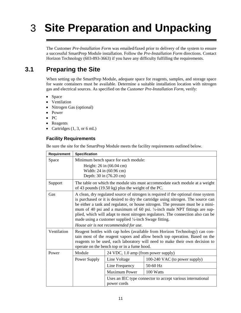
Facility Requirements Be sure the site for the SmartPrep Module meets the facility requirements outlined below.
Requirement Specification Space Minimum bench space for each module:
Height: 26 in (66.04 cm) Width: 24 in (60.96 cm) Depth: 30 in (76.20 cm)
Support The table on which the module sits must accommodate each module at a weight of 43 pounds (19.50 kg) plus the weight of the PC.
Gas A clean, dry regulated source of nitrogen is required if the optional rinse system is purchased or it is desired to dry the cartridge using nitrogen. The source can be either a tank and regulator, or house nitrogen. The pressure must be a mini-mum of 40 psi and a maximum of 60 psi. ⅛-inch male NPT fittings are sup-plied, which will adapt to most nitrogen regulators. The connection also can be made using a customer supplied ⅛-inch Swage fitting. House air is not recommended for use.
Ventilation Reagent bottles with cap holes (available from Horizon Technology) can con-tain most of the reagent vapors and allow bench top operation. Based on the reagents to be used, each laboratory will need to make their own decision to operate on the bench top or in a fume hood.
Power Module 24 VDC, 1.0 amp (from power supply) Power Supply Line Voltage 100-240 VAC (to power supply)
Line Frequency 50-60 Hz Maximum Power 100 Watts Uses an IEC type connector to accept various international power cords

3: Site Preparation and Unpacking
12
Requirement Specification SPE Cartridges
You will need to supply 1, 3, or 6 mL SPE cartridges.
Reagents Reagents are required to condition, wash, and elute the SPE cartridges. Review the chemistry method(s) that will be automated, and make sure these reagents are on hand. As SPE cartridges use very small volumes of reagents, a 500-mL container would be suitable for most applications. Reagent bottles are available from Horizon Technology.
Collection Tubes
Collection tubes should have been selected at the time of purchase so the proper rack can be supplied.
Waste Containers
You need to supply the waste containers if you did not purchase the 20 liter plastic carboy (PN: 49-2818-03) with your SmartPrep Extractor. The SmartPrep Module has 3 waste port lines and one drain line from the waste block. You determine the destination of lines 1, 2, and 3. For example, the container used for the wastewater should be greater than 12 liters, if 12 one-liter samples are to be run. If smaller sample sizes are to be processed, a smaller wastewater container could be used. For reagent wastes, containers of 500 mL are suitable. It is important to locate a position for the waste container(s) below the SmartPrep Extractor for proper drainage as shown pictured here:

3.2: Unpacking the SmartPrep Module
13
3.2 Unpacking the SmartPrep Module Follow the steps below when unpacking the SmartPrep Module. Call Horizon Technology at 603-893-3663 or your local supplier for any assistance required for your installation.
Step 1: The SmartPrep Module is delivered in a shipping container with the base module and accessories. Open the box carefully without slicing into the flap seams.
You will see the accessories boxes inside the main shipping container, as shown in Figure 3-1. (The accessories boxes sit on top of the SmartPrep Module, as described below.)
Step 2: Remove the accessories boxes and set them aside. Remove the top foam piece.
Figure 3-1. SmartPrep Accessories Box (Looking Down into the Shipping Container)
After removing the accessories boxes and foam piece, you will see the SmartPrep Module (Fig. 3-2).
Figure 3-2. SmartPrep Base Module in the Shipping Container
Step 3: Carefully lift the SmartPrep Module from the shipping container, as shown in Figure 3-3.

3: Site Preparation and Unpacking
14
Figure 3-3. Lift the SmartPrep Module from the Shipping Container
Note the manner in which you should handle the SmartPrep Module for transport:
Figure 3-4. Transport the SmartPrep Module
Step 4: Place the SmartPrep Module on the desired work surface.
Step 5: Unpack the accessories box and set each component on the table.
Step 6: Check to be sure you have the SmartPrep Module components, as shown in Figure 3-5 and listed be-low. You should have one of each component unless otherwise noted.
If any parts are damaged or missing, contact Horizon Technology immediately.
Sample Collection Rack (in a separate box) Gas Feed Tubing Kit (black tubing in bag), used for connecting multiple SmartPrep Mod-
ules to a single nitrogen regulator Reagent and Sample Tubing (factory installed) Plunger Assembly (factory installed on the module)

3.2: Unpacking the SmartPrep Module
15
Drip Tray Universal Power Transformer and Cord (100-240 VAC input) USB Connection Cable (module to computer or hub, if multiple units used) Cleaning Cartridge (x1)
Figure 3-5. SmartPrep Module and Accessories
Step 7: Check to be sure you have the SmartPrep Starter Kit components, as shown in Figure 3-6 and listed below. You should have one of each component.
The Starter Kit is provided in one of two configurations: with a PC Controller that supports up to 8 modules (part number 49-2807-01) or without a PC Controller (part number 49-2807-02).
If any parts are damaged or missing, contact Horizon Technology immediately.
Nitrogen Gas Regulator/Bracket Assembly CD with Operating Software, Methods, and User Documentation USB with Operating Software, Methods and User Documentation PC Controller (optional)
Figure 3-6. SmartPrep Starter Kit
Step 8: Check to be sure you also have the following items (not supplied with the SmartPrep Module, ac-cessories, or Starter Kit). The items are required to complete the installation:
Nitrogen Gas Regulator/Bracket
Assembly
Optional PC Controller (not shown)
CD with Operating Software, Methods,
and User Documentation
Syringe and Plunger Assembly (factory installed)
USB Connection Cable
Universal Power Transformer and Cord
Drip Tray
Gas Feed Tubing Kit (black tubing in bag)
Cleaning Cartridge (x1)
Start Card
USB Stick with Operat-ing Software, Methods, and User Documenta-tion

3: Site Preparation and Unpacking
16
Item A gas supply (dry N2) capable of minimum 40 psi to maximum 60 psi Reagent and water waste containers
Three containers typically are used to collect non-chlorinated, chlorinated, and water waste. Reagents to perform the proper chemistry USB Hub for connecting multiple modules (PN 63-2800-01) Cartridges for the method you intend to implement Cartridge Inserts if you have a 3-mL or 1-mL cartridge system
Step 9: Review the information in Section 4, SmartPrep Hardware Overview, to become familiar with the system components.
Step 10: Horizon Technology offers a number of optional components and supplies. Check to determine if you need any of these optional items:
Collection Racks (Custom racks available) Part Number Collection rack for 20 mL tubes (12 position) Collection rack for 40 mL tubes (12 position) Collection rack for 13 x 100 mL tubes (12 position)
49-2812-01 49-2812-02 49-2812-03
Collection Rack, 2x6 for conical bottom centrifuge tube with ground glass top 15 x 100 mm (12 position)
Collection Rack, 2x6 for “ELKA”, AR®/soda glass, round bottom, with rim, 15.5 x 100 mm tubes (12 position)
49-2812-06 49-2812-07
Collection Rack, 2x6 for 20-mL crimp-top rounded bottom Headspace vial 22 x 75 mm, 20-mm collar (12 position)
Collection Rack, 2x6 for custom conical bottom graduated test tube 17 x 100 mm to hold 10 mL (12 position)
Collection Rack, 2x6 for standard 16 x 100 mm test tubes (12 position)
49-2812-09 49-2812-10 49-2812-11
Plunger Assemblies
Plunger Assembly Kit for 1 mL cartridges Plunger Assembly Kit for 3 mL cartridges Plunger Assembly Kit for 6 mL cartridges
You must also have the appropriate Cartridge Stripper block, below.
49-2100-01 49-2300-01 49-2600-01
Cartridge Stripper Block (to match plunger size) Cartridge stripper block for 1 mL cartridges Cartridge stripper block for 3 mL cartridges Cartridge stripper block for 6 mL cartridges
49-2100-02 49-2300-02 49-2600-02
Piercing Plunger for Gel Immuno-Affinity Cartridges (includes special stripper block)
1-mL Piercing Plunger assembly (with special stripper block). 49-2100-11
6 and 3-mL Piercing Plunger assembly (with special stripper block) 49-2600-11 Cartridge Inserts for Carousel
Inserts for 1 mL cartridges (15 per pack) Inserts for 3 mL cartridges (15 per pack)
Choose a cartridge insert when purchasing a 1 mL or 3 mL plunger assembly.
49-2100-03 49-2300-03
Sample Sip Tubes 10” Stainless steel sip tubes with male PolyPro barb attached (12 per
pack) 49-2810-02

3.2: Unpacking the SmartPrep Module
17
10” Stainless steel sip tubes with Kynar® barb (12 per pack) 10” PEEK sip tubes with compression fitting installed for large sample
containers (12 per pack) 5” Stainless steel sip tubes with male PolyPro barb attached (12 per
pack) 5” Stainless steel sip tubes with Kynar® barb (12 per pack) 5” PEEK sip tubes with compression fitting installed for smaller sample
containers (12 per pack)
49-2810-12 49-2810-22 49-2810-03 49-2810-13 49-2810-23
Sample Filters, Disposable In-Line Membrane Sample Filters 3.1 micron membrane filters (50 per pack) 49-2814-01
Septa Septa, 100 per pack 49-2817-02
Cleaning Cartridges Cleaning Cartridges, 6 mL (50 per pack) 49-2600 Cleaning Cartridges, 3 mL (50 per pack) 49-2300
Cleaning Cartridges, 1 mL (50 per pack) 49-2100 Sample Bottle Rack
Universal tilting sample rack (4, 1 liter bottles or 12, 40 mL VOA tubes) 49-2815-01
Sample Rinse Kit Sample Rinse Kit (for 6 sample bottles) 49-2810-01
Rinse Nozzle Kit Boston Round, (6 per pack) 49-2810-04
Reagent Bottles Reagent bottles 49-2816-01
Collection Tubes Collection tubes, 20 mL VOA tubes (case of 72) Collection tubes, 40 mL VOA tubes (case of 72)
160-0008-02 160-0008
Collection Accessories
Collection tube caps with opening for 20 and 40 mL VOA tubes (12 per pack)
Collection tube foil
49-2817-01 EZ-SEALS-HT
Waste Containers 20 liter plastic carboy without drain 49-2818-03
Drip Tray Kit Drip Tray Kit 49-2819-01
Containment Pan Spill Containment Pan for a Single SmartPrep Module 99-2810

3: Site Preparation and Unpacking
18
Notes:

19
SmartPrep Hardware Overview 4
You should be completely familiar with all parts and functions of the SmartPrep Module before you start to use it. This section provides an overview.
4.1 Front and Side Features
Figure 4-1. Front and Side View
Part Function Touch Screen Display
The Touch Screen display provides visual feedback on the current status of the module. It enables you to control and interact with the module. The display includes features to Start, Pause, Resume, and/or Abort the module. It also displays other useful information.
Cartridge Plunger The plunger assembly is a shaft with a chemically resistant o-ring on the end, which seals against the top frit of the SPE cartridge. This leak-tight seal allows reagents, samples, and nitrogen gas to pass through the SPE packing material without leakage. The plunger assembly is easily changed to accommodate 1, 3, 6-mL or buffer filled cartridges.
Power Switch This switch provides the 24 VDC power to the module. Power is indicat-ed when the Touch Screen display is illuminated.
Cartridge Carousel
The SPE cartridge carousel has a total of 21 positions. The current con-figuration uses positions 1 through 12 for 1, 3 or 6-mL cartridges. The carousel is designed to handle a standard 6 mL cartridge. Inserts are used for 1 or 3-mL cartridges. Positions 13 through 20 are for future capabilities. Position 21 is always used for a cleaning cartridge.
(Continued on the next page.)
Nitrogen Gas Valves
Touch Screen Display
Cartridge Plunger
Power Switch
Cartridge Carousel
Collection Tube Rack
Syringe Pump /Liquid Sensor
12-Port Switching Valves for Reagent (V1) and Sample (V2)
Reagent Mixing Chamber/ Reservoir
Drip Tray

4: SmartPrep Hardware Overview
20
Part Function Drip Tray The Drip Tray will prevent any liquid drops from the cartridge barrels
from dripping into a collection tube or onto the chassis. The Drip Tray is held in place with two screws and is easily removed for cleaning.
Collection Tube Rack
The 12-position rack is located in the bottom, front of the module. The rack must be in position and filled with the proper number of collection tubes before the module is operated. Various racks are available to ac-commodate different tube sizes.
Nitrogen Gas Valves
Two nitrogen gas valves (SPE Cartridge Pressure - N2P1 and Sample Pressure - N2P2) are used to assist with the transfer of liquids through the tubing, and to purge the cartridges of any residual liquids. It is preferable to dry with nitrogen if there is any concern about potential oxidation of the sample.
Syringe Pump / Liquid Sensor
The syringe pump performs all liquid dispense and aspirate functions. The syringe draws up reagent or sample through the 12-port valves, and dispenses it back to the SPE cartridge via the cartridge plunger. The liq-uid sensor option is used to ensure liquid is in the syringe and, based on the method used, take corrective action if no liquid is present.
12-Port Switching Valves
Two 12-port switching valves are used. The reagent valve (V1), which is located closest to the syringe pump, is used to select the desired reagent. It connects the syringe to the cartridge plunger assembly. Liquids flow through one of the following ports, as specified in the method: • Reagents 1 through 8 • Mixing Chamber / Reservoir • Vent • Cartridge Plunger • Sample Pressure Nitrogen Valve (N2P2) The sample valve (V2) is connected to the Sample Pressure Nitrogen Valve (N2V2) and is used to pull samples from their containers and direct the sample to the SPE cartridge.
Reagent Mixing Chamber / Reservoir
This chamber serves two purposes: • It allows reagents to be added to this chamber, so reagent mixtures of
any ratio can be prepared. This is very useful when gradient reagent mixtures are needed.
• The chamber serves as a reservoir when pulling reagent from a sample container. Parking the rinse reagent in the mixing chamber ensure that a continuous volume of reagent is delivered to the SPE cartridge.

4.2: Back Panel Features
21
4.2 Back Panel Features
Figure 4-2. Back Side View
Part Function
SPE Cartridge (N2P1) - Low Pressure Nitrogen Gas Inlet Fitting
N2P1 is used for low pressure nitrogen to purge the SPE cartridge of residual reagents and water, with pressure typically at 5–10 psi. N2P1 is connected directly to V1 (refer to the description of the Re-agent Valve and the Plunger). The gas pressure is controlled from the nitrogen gas regulator/bracket assembly. (Refer to Figure 5-2)
Sample (N2P2) – Nitrogen Gas Inlet Fit-ting
N2P2 is used for nitrogen to spray reagent rinse directly into the sample bottle, with pressure for Clean Sample Lines and sample homogenization at 2-4 psi and Bottle Rinsing at 10-20 psi. N2P2 is connected directly to the sample valve V2 (refer to the description of 12-Port Switching Valves). The gas pressure is controlled from the nitrogen gas regulator/bracket assembly. (Refer to Figure 5-2)
USB Comm Port This port connects the SmartPrep Module to the PC Controller. It is used to download all methods and commands to the module.
24 VDC Power Receptacle
This receptacle delivers 24 VDC power to the module from the power supply.
Future Comm Port This expansion port will enable the SmartPrep Module to directly power and control future modules and accessories. This will further enhance the capabilities of the SmartPrep Module.
(Continued on the next page.)
USB Comm Port
Labels
N2P1 – Low Pressure Nitrogen Gas Inlet Fitting
N2P2 – High Pressure Nitrogen Gas Inlet Fitting
Power: 24 VDC Power Receptacle
Expansion: Future Comm Port
Waste Port Fittings W1, W2, W3 (user definable)
Waste Block Drain

4: SmartPrep Hardware Overview
22
Part Function
Waste Port Fittings Three waste port fittings (W1, W2, and W3) allow you to direct rea-gent waste to specific waste containers. Segregating reagent waste can save considerably on all disposal costs. The fourth port fitting, located below the other three, is used to drain liquids from the Waste Block. .
Labels These labels identify the serial number as well as CE and ETL Certification.
Figure 4-3. Label Location
Labels

4.2: Back Panel Features
23
Notes:
24
Installing the SmartPrep Module 5The SmartPrep Module is easy to install. This section includes instructions to install a single module (Section 5.1) and multiple modules (Sections 5.1 and 5.2). The section concludes with the software installation procedure (Section 5.3).
5.1 Installing a SmartPrep Module Follow these instructions to install a SmartPrep Module. (If you are installing multiple modules, follow the instructions below and then continue with Section 5.2)
Step 1: With the SmartPrep Module placed on the desired work surface, angle the module slightly so you can access the back panel.
Step 2: Cut the tie wrap holding the waste lines, and direct these lines to the proper waste containers. The fourth waste line is the overflow drain line for the waste block. This line can be directed to anyone of the 3 waste containers.
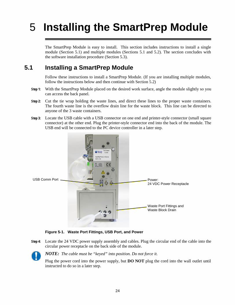
Step 3: Locate the USB cable with a USB connector on one end and printer-style connector (small square connector) at the other end. Plug the printer-style connector end into the back of the module. The USB end will be connected to the PC device controller in a later step.
Figure 5-1. Waste Port Fittings, USB Port, and Power
Step 4: Locate the 24 VDC power supply assembly and cables. Plug the circular end of the cable into the circular power receptacle on the back side of the module.
NOTE: The cable must be “keyed” into position. Do not force it.
Plug the power cord into the power supply, but DO NOT plug the cord into the wall outlet until instructed to do so in a later step.
USB Comm Port Power: 24 VDC Power Receptacle
Waste Port Fittings and Waste Block Drain
5.1: Installing a SmartPrep Module
25
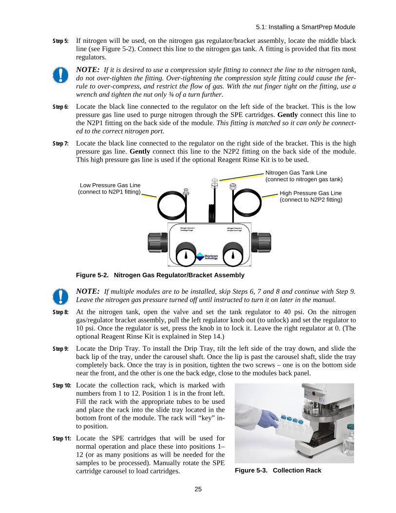
Step 5: If nitrogen will be used, on the nitrogen gas regulator/bracket assembly, locate the middle black line (see Figure 5-2). Connect this line to the nitrogen gas tank. A fitting is provided that fits most regulators.
NOTE: If it is desired to use a compression style fitting to connect the line to the nitrogen tank, do not over-tighten the fitting. Over-tightening the compression style fitting could cause the fer-rule to over-compress, and restrict the flow of gas. With the nut finger tight on the fitting, use a wrench and tighten the nut only ¾ of a turn further.
Step 6: Locate the black line connected to the regulator on the left side of the bracket. This is the low pressure gas line used to purge nitrogen through the SPE cartridges. Gently connect this line to the N2P1 fitting on the back side of the module. This fitting is matched so it can only be connect-ed to the correct nitrogen port.
Step 7: Locate the black line connected to the regulator on the right side of the bracket. This is the high pressure gas line. Gently connect this line to the N2P2 fitting on the back side of the module. This high pressure gas line is used if the optional Reagent Rinse Kit is to be used.
Figure 5-2. Nitrogen Gas Regulator/Bracket Assembly
NOTE: If multiple modules are to be installed, skip Steps 6, 7 and 8 and continue with Step 9. Leave the nitrogen gas pressure turned off until instructed to turn it on later in the manual.
Step 8: At the nitrogen tank, open the valve and set the tank regulator to 40 psi. On the nitrogen gas/regulator bracket assembly, pull the left regulator knob out (to unlock) and set the regulator to 10 psi. Once the regulator is set, press the knob in to lock it. Leave the right regulator at 0. (The optional Reagent Rinse Kit is explained in Step 14.)
Step 9: Locate the Drip Tray. To install the Drip Tray, tilt the left side of the tray down, and slide the back lip of the tray, under the carousel shaft. Once the lip is past the carousel shaft, slide the tray completely back. Once the tray is in position, tighten the two screws – one is on the bottom side near the front, and the other is one the back edge, close to the modules back panel.
Step 10: Locate the collection rack, which is marked with numbers from 1 to 12. Position 1 is in the front left. Fill the rack with the appropriate tubes to be used and place the rack into the slide tray located in the bottom front of the module. The rack will “key” in-to position.
Step 11: Locate the SPE cartridges that will be used for normal operation and place these into positions 1–12 (or as many positions as will be needed for the samples to be processed). Manually rotate the SPE cartridge carousel to load cartridges.
Nitrogen Gas Tank Line (connect to nitrogen gas tank)
High Pressure Gas Line (connect to N2P2 fitting)
Low Pressure Gas Line (connect to N2P1 fitting)
Figure 5-3. Collection Rack

5: Installing the SmartPrep Module
26
Step 12: Locate the SPE cleaning cartridge. This is a standard cartridge body, but it has no packing materi-al (features 3 or 4 frits, depending on the size). Manually rotate the SPE cartridge carousel until position 21 is in the front. Place the cleaning cartridge into position 21.
Step 13: Follow the instructions below to install the Sample Bottle Rinse Kit if you have this option.
The Sample Bottle Rinse Kit is an option that sprays reagent directly into the sample bottle, washing the container walls and ensuring better recovery values for environmental methods. When the rinse kit is used, the total number of samples that a single SmartPrep Module can pro-cess is reduced from 12 to 6 because sample lines 7 through 12 are used to deliver the reagent to sample bottles 1 through 6.
Follow these instructions to install the Sample Bottle Rinse Kit:
a. Locate the Sample Bottle Rinse Kit which consists of two parts, (6) Rinse Tubes and the Sol-vent Line Enclosure Kit. It consists of 6 spray nozzles attached to sample bottle caps, the rinse module box, and connecting tubing.
b. Place the rinse module box on the right or left side of the SmartPrep Module.
c. On the sample valve (V2), which is located closest to the back panel of the chassis, identify line 7. Numbered bands on each line aid in the identification of a line.
d. Using a piece of paper towel, firmly but carefully so as not to bend the tubing, press the end of line 7 onto the barb fitting 7 at-tached to top of the rinse module box. The barb fitting can be removed from the rinse module box to make connecting the tubing to the barb easier.
e. Repeat Steps 13c and 13d for lines 8 through 12.
f. On the front face of the rinse module box, connect one of the external lines that came with the Solvent Line Enclosure Kit to fitting 1 and connect the other end to one of the rinse cap as-semblies. Use gentle force when connecting this fitting.
g. Repeat Step 13f for the remaining Enclosure Kit ports 2 through 6.
h. Slide the rinse module box back so the back edge of the rinse module box is flush with the back edge of the SmartPrep Module. This will maximize the usable bench top surface. Sample Lines 1-7 on the SmartPrep Module will connect to the Rinse Cap Assembly with the corre-sponding number in step 13f and 13g.
Step 14: Plug the SmartPrep power cord into a wall outlet. Toggle the front power switch to turn on the module. The front Touch Screen display will light up.
The module installation is complete. If you are installing multiple modules, continue with Section 5.2. If you are installing a single module, you are ready to load the software onto the PC Control-ler and configure the module, as described in Section 5.3.
NOTE: The SmartPrep Module is shipped with the ordered plunger assembly installed. If a dif-ferent sized cartridge is to be used, the plunger assembly must be changed. See Section 11.2.
5.2 Installing Multiple SmartPrep Modules
Figure 5-4 . Bottle Rinse Kit, showing the Rinse Module Box with lines going to sam-ple bottle caps from the front of the box and connectors for corresponding lines going to the sample valve (V2), on the top.

5.3: Installing the SmartPrep Module Software
27
Step 1: Place the second module in the desired location. It must be close enough for the USB cable to reach the PC Controller or the USB hub.
Step 2: Repeat Steps 1 through 4 of Section 5.1.
Step 3: Locate the Gas Feed Tubing Kit (P/N 49-2820-01, which is shipped as part of the SmartPrep Module). The gas feed tubing as-sembly feeds nitrogen gas to the second mod-ule.
NOTE: There are two lines and each line has different end caps and fittings. This is to en-sure that only the low pressure gas can be connected to the low pressure port, and only the high pressure gas can be connected to the high pressure fitting.
Step 4: On the back side of the first module, discon-nect the low pressure nitrogen fitting—the one closest to the top of the chassis. Using the ap-propriate line from the Gas Feed Tubing Kit, gently connect the fittings together. Reconnect the short T-section to the first module and the longer end to the second module. Repeat this Step for the high pressure nitrogen gas.
Step 5: Repeat Steps 8 through 13 in Section 5.1.
Step 6: If the Sample Bottle Rinse Kit is to be used, repeat Step 14 in Section 5.1.
The multiple module installation is complete. You are ready to load the software onto the PC Controller and configure each module, as described in Section 5.3, below.
NOTE: If desired, multiple modules can pull reagents from the same reagent container. Posi-tion the reagent containers such that the reagent lines will reach the containers. If desired, rea-gents can be manifolded together. Contact Horizon Technology for information on how to do this.
5.3 Installing the SmartPrep Module Software The SmartPrep Module software must be installed on a computer running a Windows Operating System. Windows XP, Windows 7, Windows 8 or Windows 10 is required. The software still needs to be loaded even if you purchased the PC Controller from Horizon Technology.
Step 1: Locate the CD or USB memory stick that came with the SmartPrep Module.
Step 2: Insert the CD into the CD drive on the PC. The CD will automatically open the program and begin the installation. The USB stick will require that the directions in the NOTE are followed. Open the directory for the USB drive and double-click the setup.exe file to start the routine.
NOTE: If the software installation does not begin automatically, open to view the CD directory and double-click the setup.exe file to start the routine.
Step 3: Follow the instructions on the screen to load the software. The first screen to appear is shown be-low. Click Next to begin the installation process.
Figure 5-5. Connection of the nitrogen gas lines to allow one regulator to serve multiple Modules.

5: Installing the SmartPrep Module
28
Figure 5-6. SmartPrep Software Installation Window
Step 4: The next screen to appear (see below) will allow you to select the directory where the software will be installed. It is suggested to use the default directory. Click Next to continue the installa-tion.
Figure 5-7. SmartPrep Installation Folder Window
Step 5: The software will now ask you to confirm the installation of the software (see below). Click Next to confirm the installation.

5.3: Installing the SmartPrep Module Software
29
Figure 5-8. SmartPrep Confirm Installation Window
Step 6: The software will begin the installation process. After the software has been successfully in-stalled, the screen shown below will appear. Click Close to exit the installation program. A Desk-top icon will be created and appear on the PC desktop.
Figure 5-9. SmartPrep Software Installation Complete Window
5: Installing the SmartPrep Module
30
NOTE: If the PC does not have an internet connection, follow Steps 7 through Step 11 to load the USB drivers. If the PC does have an internet connection, proceed to Step 12. If you have dif-ficulty loading the USB drivers, please contact Horizon Customer Support at 603-893-3663.
Step 7: Open Windows Explorer (not the Internet Explorer).
Step 8: Locate the CD drive containing the SmartPrep CD, and right-click on the SmartPrep V3.0 … name.
Step 9: Select Open.
Step 10: Open the USBDrivers folder.
Step 11: Double click on the CDM20824_Setup.exe for XP or CDM2128_Setup.exe for Win 7-10 to run this executable file. This file will load the proper USB drivers onto the PC. When the file is finished loading, close all of the windows.
Step 12: Locate the USB cable that was installed in Section 5.1, Step 3. Connect the USB end into an open USB port on the PC. Turn on the power switch on the SmartPrep and wait for the two USB driv-ers to finish loading.
Alternatively, if you are connecting multiple SmartPrep Modules, connect the USB cable from the module to an open port on the USB hub (PN 63-2800-01). Connect the hub (with included cable) to the PC Controller. Powering the hub (with the included hub power supply) is optional.
Step 13: Double-click the desktop SmartPrep icon to open the main SmartPrep Control window, as shown in Figure 5-10.
Step 14: During the software installation, a new directory named “Horizon TechnologySP” will be created on the primary PC hard drive. This directory contains all necessary files to run the SmartPrep, and copies of all methods which were included on the CD. These methods can be used as is, or modi-fied to suit specific needs. Copy methods from the Factory Methods folder to the Methods folder to have them appear as choices in the method drop-down box.
Various subdirectories are also created under the Horizon TechnologySP directory, and these subdirectories contain files critical to successful operation of the SmartPrep.
Report Number After each run sequence, a report is automatically generated and stored in the directory:
C:\Horizon TechnologySP\SmartPrep\Reports
The report number is automatically incremented by one for each run sequence made. This entry allows the report number to be reset to start again at one. Input 0 and the next report number will be #1. Each subsequent report will be incremented by 1.

5.4: Configuring the System for Operation
31
Use of the Control window is described in Section 6.1.
Figure 5-10. SmartPrep Control Window
5.4 Configuring the System for Operation The final step in installing the SmartPrep module is to use the software to configure the system for operation. Details of creating methods and using the software will be described in Sections 6-8, but the software functions needed to set up the equipment prior to operation of the hardware and software are described next. Setting up the tubing volume (TV) values is important and care should be taken to do this as accurately as possible. Some of the software operations rely on these numbers for good performance and therefore if they are incorrectly set the method may per-form below the optimum performance possible.
5.5 System Configuration—Using the Set Up Module Option The Set Up Module button accesses features to properly configure a module. When you click this button, the System Configuration window is displayed:
Figure 5-11. System Configuration Window
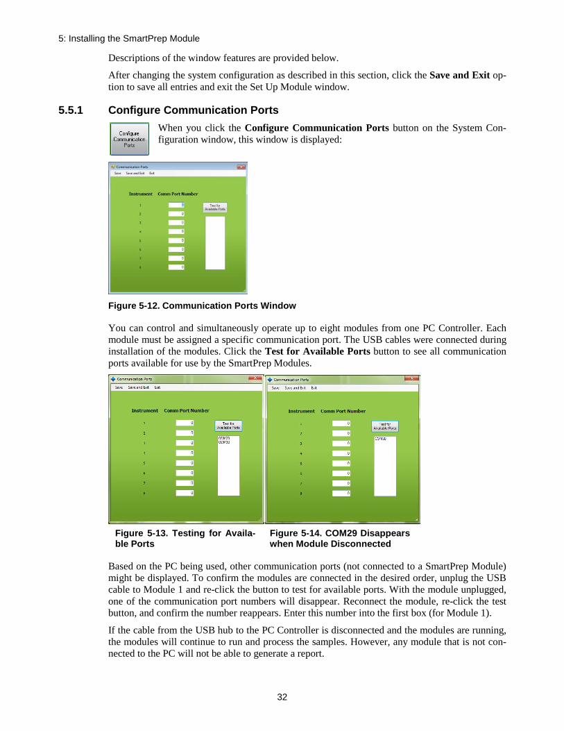
5: Installing the SmartPrep Module
32
Descriptions of the window features are provided below.
After changing the system configuration as described in this section, click the Save and Exit op-tion to save all entries and exit the Set Up Module window.
5.5.1 Configure Communication Ports When you click the Configure Communication Ports button on the System Con-figuration window, this window is displayed:
Figure 5-12. Communication Ports Window
You can control and simultaneously operate up to eight modules from one PC Controller. Each module must be assigned a specific communication port. The USB cables were connected during installation of the modules. Click the Test for Available Ports button to see all communication ports available for use by the SmartPrep Modules.
Based on the PC being used, other communication ports (not connected to a SmartPrep Module) might be displayed. To confirm the modules are connected in the desired order, unplug the USB cable to Module 1 and re-click the button to test for available ports. With the module unplugged, one of the communication port numbers will disappear. Reconnect the module, re-click the test button, and confirm the number reappears. Enter this number into the first box (for Module 1).
If the cable from the USB hub to the PC Controller is disconnected and the modules are running, the modules will continue to run and process the samples. However, any module that is not con-nected to the PC will not be able to generate a report.
Figure 5-13. Testing for Availa-ble Ports
Figure 5-14. COM29 Disappears when Module Disconnected
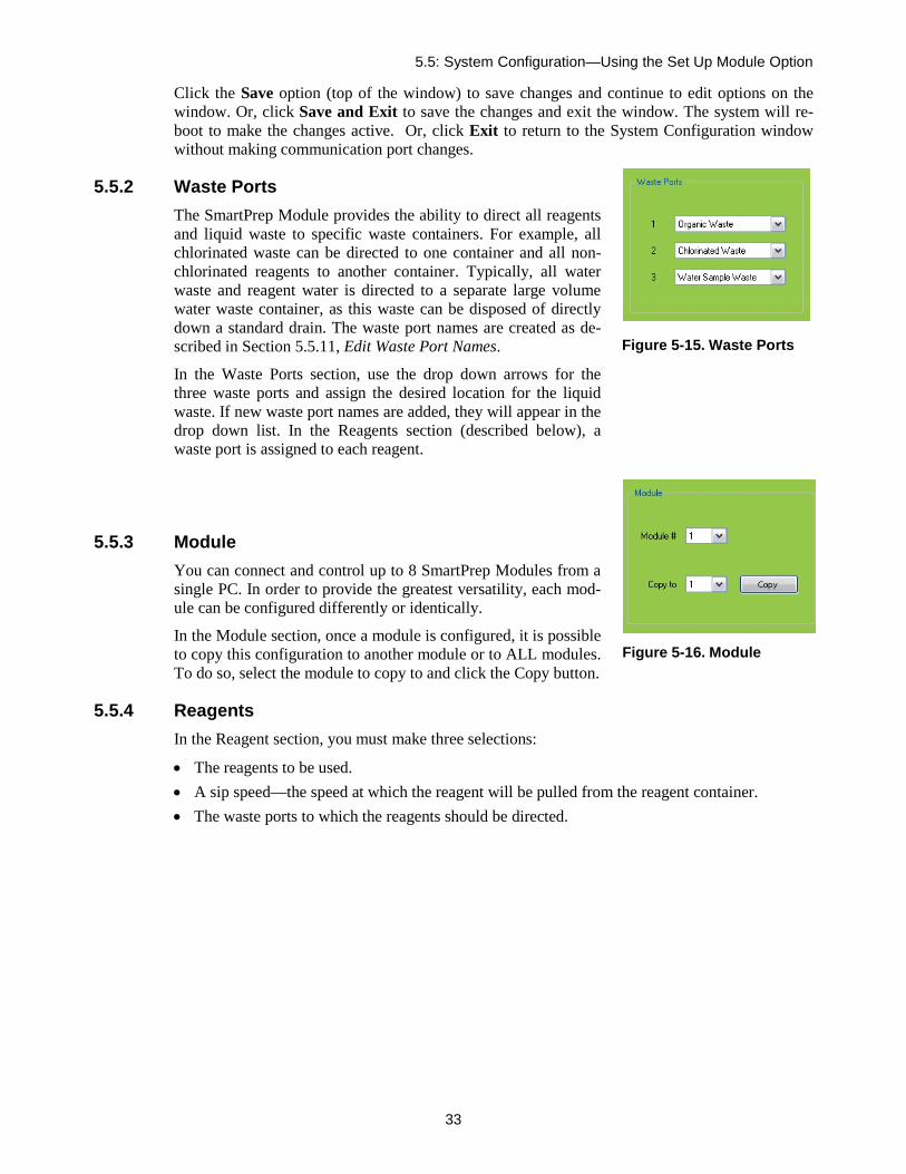
5.5: System Configuration—Using the Set Up Module Option
33
Click the Save option (top of the window) to save changes and continue to edit options on the window. Or, click Save and Exit to save the changes and exit the window. The system will re-boot to make the changes active. Or, click Exit to return to the System Configuration window without making communication port changes.
5.5.2 Waste Ports The SmartPrep Module provides the ability to direct all reagents and liquid waste to specific waste containers. For example, all chlorinated waste can be directed to one container and all non-chlorinated reagents to another container. Typically, all water waste and reagent water is directed to a separate large volume water waste container, as this waste can be disposed of directly down a standard drain. The waste port names are created as de-scribed in Section 5.5.11, Edit Waste Port Names.
In the Waste Ports section, use the drop down arrows for the three waste ports and assign the desired location for the liquid waste. If new waste port names are added, they will appear in the drop down list. In the Reagents section (described below), a waste port is assigned to each reagent.
5.5.3 Module You can connect and control up to 8 SmartPrep Modules from a single PC. In order to provide the greatest versatility, each mod-ule can be configured differently or identically.
In the Module section, once a module is configured, it is possible to copy this configuration to another module or to ALL modules. To do so, select the module to copy to and click the Copy button.
5.5.4 Reagents In the Reagent section, you must make three selections:
• The reagents to be used. • A sip speed—the speed at which the reagent will be pulled from the reagent container. • The waste ports to which the reagents should be directed.
Figure 5-15. Waste Ports
Figure 5-16. Module

5: Installing the SmartPrep Module
34
Figure 5-17. Reagents
Use the drop down arrows to select the reagents which will be used for the method to be run. To make the installation and configuration easy, the reagents do not need to be listed in the order they will be used in the actual method. When a method is run, the method looks for the needed reagent, and will automatically map to the correct port on the 12-port valve so the desired reagent will be delivered to the cartridge. It is possible to use up to 8 reagents in a method. If a reagent needed does not appear, refer to section 5.5.9 on how to add it.
Once the reagents are selected, enter a sip speed (in mL/min). A default value of 30 mL/min is used, however, the user should change this value to a lower sip speed for more viscous reagents or reagents that might outgas. Speeds greater than 50 mL/min will cause an error message.
Figure 5-18. Error message for sip speed
The last step is to select the waste port to which each reagent will be directed. (The waste port names are created as describe in Section 5.5.11, Edit Waste Port Names) Directing the reagent to the proper waste container is accomplished by a multiport waste block, which shuttles back and forth under the SPE cartridges. As the reagent is pushed through the cartridge, either with the sy-ringe plunger or nitrogen gas, the reagent is directed to the specific waste container. This allows reagents to be disposed of properly.
During certain operations, it might be desirable to use the Mixing Chamber and/or the Vent Port. Both of these features allow user-defined Sip Rates to be entered. The Sip Rate is the rate in

5.5: System Configuration—Using the Set Up Module Option
35
mL/min that liquid in the Mixing Chamber or air through the Vent Port is pulled into the syringe. The Dispense Rates for both the Mixing Chamber and the Vent Port are set when a method is composed.
5.5.5 Plunger Size If a 1 or 3 mL cartridge is desired, select the plunger size using the drop down arrow. Each module can run only one cartridge size at a time because the plunger assembly is specific to the car-tridge barrel diameter. Therefore, by configuring a module to use a specific size cartridge, only methods that were configured with the same sized cartridge will run. Methods configured with a dif-ferent size cartridge will display a warning message indicating the wrong size plunger assembly is present and the plunger assembly or method must be changed before the method(s) will run.
5.5.6 Bottle Rinse Configuration Each module can be equipped with the optional Reagent Rinse Bottle Kit. If the Kit is to be used, select this option from the drop down list. Methods written to include this Reagent Rinse option are specific and should only be run with a properly configured module. When the Rinse Kit is used, the total number of samples that can be processed drops from 12 to 6 because ports 7 through 12 on the sample valve are used to deliver the Reagent Rinse to sample bottles 1 through 6. A message will be displayed on the SmartPrep Control window screen if Bottle Rinse is being used, and only 6 sam-ples can be processed.
5.5.7 Tubing Volume To ensure that all air is removed from the tubing during specific operations, three tub-ing volume values can be entered:
• The TV1 tubing volume between the sy-ringe and inlet port on the reagent valve V1 (usually 0),
• The TV2 tubing volume between the sy-ringe and reagent valve common inlet.
o If you are not using sip tubes and only the tubing connected to the sample valve, then the TV2 value is approximately 2.1-2.2 mL
o If you are using a 5-inch sip tube connected to the tubing going to the sample valve, then the approxi-mate value for TV2 is 2.75 mL
o If you are using a 10-inch sip tube connected to the tubing going to the sample valve, then the approxi-mate value for TV2 is 3.0 mL
Figure 5-19. Plunger Size
Figure 5-20. Bottle Rinse Configuration
Figure 5-22. Tubing Vol-ume (TV)
Figure 5-21. Illustration of the flow path for TV2 (blue) and TV3 (orange)

5: Installing the SmartPrep Module
36
The TV2 tubing volume between Port 2 on the reagent valve V1 and the tip of the sample inlet sip tube will be used to pull that specific volume of Reagent Water from the appropriate reagent bottle and deliver this down the water sample line. Enter the appropriate value into the second box. Using the tubing volumes entered here, this volume of reagent water will be pulled into the syringe and directed down the sample line of the sample to be loaded. All air in the line will be dispensed into the sample bottle and replaced with reagent water. When the sample is loaded into the cartridge, no air will be present. This volume of reagent water, which is used to fill the sample line (to remove residual air), will be added automatically to the total volume of the water sample to be processed. This operation will ensure successful and reproducible chemistry.
NOTE: When a value is entered into the second Volume box, the software looks for and must find Reagent Water as one of the available reagents. If Reagent Water is not listed, the first rea-gent in the reagent list will be used instead. If Reagent Water is not configured and available, en-ter 0 into the second Volume box.
If a solvent line needs to be trimmed, the value for TV2 must be recalculated.
• The TV3 tubing volume between the sample line inlet and inlet of the reagent valve V1, is usually set to 0.2-0.3. This is the volume of air that will be automatically pulled into the sy-ringe, such that the end of the sample can be pushed out and towards the SPE cartridge.
5.5.8 Verifying the Optimal Tubing Volume Values
Visual Verification
The Manual Control capability of the SmartPrep is primarily designed to allow a trained Service Engineer full control to test and troubleshoot the module. The Manual Control also allows an ex-perienced user to create a sequence of steps for method development, and/or to determine the op-timal set of conditions for a specific chemistry. The Manual Control will be used to determine the optimal Tubing Volume (TV) values for use with the Load Sample for Cleanup and Load Small Volume Sample operations. It is important to remember that the use of Manual Control by-passes the normal safe operation of the SmartPrep, which could cause damage to the unit. Follow these steps carefully.
Visual Verification Process Step 1: Make sure the SmartPrep is turned on, and in communication with the PC.
Step 2: At the PC, from the main screen, click the Advanced Options button.
Step 3: On the Advanced Options screen, click the Manual Control Button.
Step 4: In the white box, located in the upper left, click the arrow to see a list of all available actions.
Step 5: Click on Valve 1 Home
Step 6: Once this is shown in the white box, click the Run Step button. You will hear the reagent valve rotate to its “home” position.
Step 7: Click the down arrow again, and click on Valve 2 Home. Now click the Run Step button. You will hear the sample valve rotate to its “home” position.
Step 8: Repeat the following steps, by selecting the action, entering in the
Figure 5-23. Visual verification of the TV3 value.

5.5: System Configuration—Using the Set Up Module Option
37
correct value, and clicking the Run Step button.
Step 9: Syringe Home. This will “home” the syringe by driving the syringe to the 0 volume mark.
Step 10: Syringe Speed. Replace the default 40 with 2.5. This will cause the syringe pump to move at a rate of 2.5 mL/min.
Step 11: Valve 1 Position. Enter 2. This will cause the reagent valve to rotate and connect with the sam-ple valve.
Step 12: Valve 2 Position. Enter 1. This will cause the sample valve to rotate to the first sample position.
Step 13: Place the sample line #1 into the sample container. Make sure the tip of the sample tube is not blocked, or restricted by the bottom of the sample container.
Step 14: Syringe Position. Enter 2.00. This will cause the syringe plunger to pull up 2.00 mL. As the sy-ringe moves up, observe the sample being pulled into the sample tube. When the syringe stops, observe the position of the front end of the sample. The optimal position is for the sample to be pulled completely through the sample valve, and just beyond the center port of the reagent valve. Based on the location of the sample front, either increase, or decrease the Syringe Position value, until the sample front is just beyond the center port of the reagent valve. If the SS Sip Tubes are being used, a value of up to 3.1 may be needed.
Step 15: Once the sample front is in the correct location, record this Syringe Position value. This will be the TV2 value entered on the Setup screen. Typical TV2 values on a new SmartPrep Extractor system range from 1 mL (without sip tubes) to 3.0 mL (with sip tubes).
Step 16: Syringe Position. Enter 0. This will return the syringe plunger to the 0 mL position.
Step 17: Exit out of Manual Control.
Step 18: Click on the Setup Module button.
Step 19: Enter the final value step 14 into the TV2 box.
Step 20: Enter a value to be optimized into the TV3 box. Typical TV3 volumes on a new SmartPrep Ex-tractor system range from 0.08 to 0.15 mL. Based on each SmartPrep, this TV3 value might need to be adjusted to be optimal. See Figure 5-19 for the steps necessary.

5: Installing the SmartPrep Module
38
Gravimetric Verification
Obtaining the weight of water transferred is a simple protocol that can be implemented to verify gravimetrically the TV2 and TV3 values and vent volumes are established correctly. The steps below walk through the protocol to use and materials.
Materials: • Gloves • Balance (4-place for volumes below 5 mL) • Plastic tubes and caps • Room temperature laboratory grade water that has been degassed • Weight of water delivered from a calibrated pipette equal to the volume(s) being tested
SmartPrep Methods:
1. A prime method should always be run as the first method to remove air from all system tubing lines.
A. The load method will be run after the prime method to first remove any liquid from the sample lines (assumes sample lines are already clean. If not, this would be an ad-ditional step) before loading the desired sample volume.
B. The operation you choose will be either Load Small Volume Sample or Load Sample for Cleanup. Es-tablishing the parameters within in the load operation is very im-portant to provide accurate deliv-ery of a small volume. Here, a sip and dispense rate of 2.5 mL/min were used, as well as a longer fill and dispense pause of 5 seconds. Establish the vent volume based on your system (see previous sec-tions on the new load operations for details).
When run together in the Method As-signment box, typically 1 sample at a time is run according to the following protocol.
Gravimetric Protocol:
Step 1: Place a bottle of degassed laborato-ry grade water on the specified rea-gent line on the SmartPrep Extractor (typically this is line 1).
Figure 5-24. Methods to use in Gravimetric verifica-tion of TV2 and TV3 values
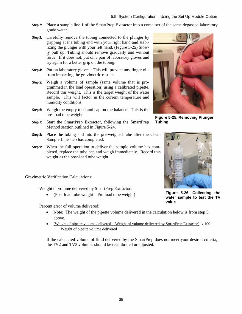
5.5: System Configuration—Using the Set Up Module Option
39
Step 2: Place a sample line 1 of the SmartPrep Extractor into a container of the same degassed laboratory grade water.
Step 3: Carefully remove the tubing connected to the plunger by gripping at the tubing end with your right hand and stabi-lizing the plunger with your left hand. (Figure 5-25) Slow-ly pull up. Tubing should remove gradually and without force. If it does not, put on a pair of laboratory gloves and try again for a better grip on the tubing.
Step 4: Put on laboratory gloves. This will prevent any finger oils from impacting the gravimetric results.
Step 5: Weigh a volume of sample (same volume that is pro-grammed in the load operation) using a calibrated pipette. Record this weight. This is the target weight of the water sample. This will factor in the current temperature and humidity conditions.
Step 6: Weigh the empty tube and cap on the balance. This is the pre-load tube weight.
Step 7: Start the SmartPrep Extractor, following the SmartPrep Method section outlined in Figure 5-24.
Step 8: Place the tubing end into the pre-weighed tube after the Clean Sample Line step has completed.
Step 9: When the full operation to deliver the sample volume has com-pleted, replace the tube cap and weigh immediately. Record this weight as the post-load tube weight.
Gravimetric Verification Calculations:
Weight of volume delivered by SmartPrep Extractor: • (Post-load tube weight – Pre-load tube weight)
Percent error of volume delivered:
• Note: The weight of the pipette volume delivered in the calculation below is from step 5 above.
• (Weight of pipette volume delivered – Weight of volume delivered by SmartPrep Extractor) x 100 Weight of pipette volume delivered
If the calculated volume of fluid delivered by the SmartPrep does not meet your desired criteria, the TV2 and TV3 volumes should be recalibrated or adjusted.
Figure 5-25. Removing Plunger Tubing
Figure 5-26. Collecting the water sample to test the TV value

5: Installing the SmartPrep Module
40
5.5.9 Edit Reagent Names When you click the Edit Reagent Names button on the System Configuration win-dow, this window is displayed:
Figure 5-27. Edit Reagent Names Window
The SmartPrep software allows for entry and storage of up to 50 reagent names. The software is preloaded with 22 of the most commonly used reagent names, enabling you to enter and store 28 additional reagent names. To add a reagent name, select the next open box and enter the name. Repeat this procedure for all reagent names to be added.
Click the Save option (top of the window) to save changes and continue to edit options on the window. Or, click Save and Exit to save the changes and exit the window. Or, click Exit to re-turn to the System Configuration window without adding a reagent name.

5.5: System Configuration—Using the Set Up Module Option
41
5.5.10 Edit Cartridge Names When you click the Edit Cartridge Names button on the System Configuration window, this window is displayed:
Figure 5-28. Edit Cartridge Names Window
The SmartPrep software allows for entry and storage of up to 40 cartridge names. The software is preloaded with 20 of the most commonly used cartridge packing materials, enabling you to enter and store 20 additional names. To add a cartridge name, select the next open box and enter the name. Repeat this sequence for all cartridge names to be added.
Click the Save option (top of the window) to save changes and continue to edit options on the window. Or, click Save and Exit to save the changes and exit the window. Or, click Exit to re-turn to the System Configuration window without adding a cartridge name.

5: Installing the SmartPrep Module
42
5.5.11 Edit Waste Port Names When you click the Edit Waste Port Names button on the System Configuration window, this window is displayed:
Figure 5-29. Edit Waste Port Names Window
The SmartPrep software allows for entry and storage of up to 10 waste port names. The software is preloaded with 3 of the most commonly used waste port names, enabling you to enter and store 7 additional names. To add a waste port name, select the next open box and enter the name. Re-peat this sequence for all waste port names to be added.
Click the Save option (top of the window) to save changes and continue to edit options on the window. Or, click Save and Exit to save the changes and exit the window. Or, click Exit to re-turn to the System Configuration window without adding a waste port name.
5.5.12 Reagent and Sample Valves The ceramic seals in the valves are extremely rugged and smooth, functioning well when coming in contact with samples of varying chemical and particulate content. Because of their smooth surface there is a small chance that they will stick to each other when left to sit for some time. The software allows a detection step to be automatically included for determining if the valve is stuck during idle time. Additionally the valve can be rotated at a set time interval by choosing the Periodic Valve Cycle check box and setting the period in minutes. If the Set Max Period button is chosen it automatically sets the num-ber of minutes to that required to exercise the valve once every 24 hours.
Figure 5-30. Rea-gent and Sample Valve Window

5.5: System Configuration—Using the Set Up Module Option
43
5.5.13 Calibration Factors When you click on Calibration in the Set Up menu bar, this window is displayed:
Figure 5-31. Calibration Factors Window
NOTE: Changing any values in the Calibration screen should only be done by a factory Service Engineer, unless directed otherwise by Horizon Technology’s Customer Support group. Entering incorrect values could cause the SmartPrep Module to not function properly, or could cause damage to the module.
Each SmartPrep Module is factory calibrated to ensure proper operation, and these calibration factors are permanently stored in each module. However, if service work has been performed, or parts have been replaced, it might be necessary to recalibrate the module.
Step 1: In the center of the screen is a box called Move to Location. Notice that all buttons within the box, except the Home Shuttle are greyed out. This is to ensure that the shuttle mechanism is first homed before the shuttle can be moved to any other position. Press the Home Shuttle button to home the shuttle. The shuttle moves back inside the chassis, moves to the far right, and then moves to the middle. The shuttle is now homed. Once the shuttle is homed, the other buttons in the box become active.
Step 2: Make sure a Cleaning Cartridge is in position #21, and then click the Offset button. This will move the carousel to position #21.
Step 3: In the box near the bottom of the window, use the scroll bar (or the left or right arrows) to set the Move Plunger time to 0.2 seconds.
Step 4: Click the Plunger Dn button. The plunger will move downward for 0.2 second. One click will move the plunger just above the opening of the cartridge barrel.
Step 5: Visually inspect the tip of the plunger to ensure that it is properly aligned over the opening of the Cleaning Cartridge. If the plunger tip is off center from the cartridge, adjust the carousel by in-creasing or decreasing the Carousel Home Offset value. Increasing the value will cause a clock-wise rotation, while decreasing the value will cause a counterclockwise rotation. Start with small incremental value changes of 50. As the carousel gets closer to the desired position, smaller Off-set values can be used. There is no need to change the Finished value, as this is the true home for the carousel optical sensor.

5: Installing the SmartPrep Module
44
Step 6: Click the W1 button. The shuttle moves and positions Waste Block Port #1 under the SPE car-tridge.
Step 7: Increase the Move Plunger slide bar to 2.0 seconds, and click the Plunger Dn button. Click this button a sufficient number of times until the luer tip of the cartridge is just above the Waste Block port.
Step 8: Looking down through the hole in the Drip Tray, you can visually determine if the Waste Block Port #1 is properly positioned beneath the cartridge luer tip. If the block is not in the proper posi-tion, do the following. If the block is too far forward, reduce the value in the Waste Y box, and press the W1 button. The shuttle will move slightly inward. Repeat this process to position the shuttle in the proper Y (front to back) orientation. Larger Waste Y values bring the shuttle out, and smaller values move the shuttle in.
Step 9: Next, look at the right and left positioning of the Waste Block. If the block is too far to the right, increase the value of the Waste 1X box. If the block is too far to the left, reduce the value of the Waste 1X box. The above steps are used to check the positioning accuracy for the Waste Block Ports #1 and #4, and Collection Tubes #1 and #12. As above, the Y positioning for Tube #1 and #12 can also be changed.
Step 10: In the upper right side of the screen are two boxes for the Plunger Run % Current and Plunger Hold % Current value. There is usually no need to change these settings unless the plunger mo-tor has been replaced or special SPE cartridges are to be used. In the case that any cartridge leaks (usually out the top of the cartridge when the plunger is inserted into the cartridge) the Plunger Run % Current setting may need adjustment. Call Horizon Technology Customer Support group.
Step 11: Below the Plunger Current value boxes is a box for the Syringe Steps/mL. This value allows fine tuning of the stepper motor that drives the syringe pump. The syringe has been factory calibrated, but if the syringe is not delivering the correct volume, this value can be changed to increase or decrease the volume of liquid being delivered. See Section Error! Reference source not found. for instructions to calibrate the syringe pump for volume accuracy.
Step 12: The Syringe Steps Before Failing During Dispense value is a pressure feedback setting for the syringe pump. Without any blockage in the SPE cartridge, the syringe pump is programmed to deliver a set number of stepper motor steps per each mL of liquid. If the SPE cartridge becomes blocked due to particulates in the sample, and the syringe begins to skip due to excessive back-pressure, the total number of allowable steps will be exceeded and an error message will be gen-erated – Blocked Cartridge. The allowable setting range is from 3720 to 5000, with 3720 being the desired starting value. If the samples being processed cause the syringe to skip contact Hori-zon Technology Customer Support group.
Step 13: The two boxes in the lower right are hour meters. The top box displays the total run time on the module. This time is incremented only when the module is running samples. The lower box is used by the Service Engineer, and is reset to 0 when any service work is performed on the mod-ule. These service hour meters are very useful when scheduling preventative maintenance work.
Click Save and Exit to save all values and exit the screen.

5.5: System Configuration—Using the Set Up Module Option
45
5.5.14 Utilities When you click on Utilities in the Set Up menu bar, this window is displayed:
Figure 5-32. Utilities Window
Run Time Computation When a method is created, all of the fixed times (such as soak and nitrogen purge) are recorded and stored in memory. Also, based on the volume and the sip and dispense speed for the reagents, the software calculates the times for these steps and adds these times to the total. In order to more accurately calculate the total method run time, the software allows the ability to input a time val-ue (in seconds) for both the Sample Overhead Time and each Step Overhead Time. The Sam-ple Overhead Time takes into account the initial set up time which will vary if Optimize Homing has been checked on the System Configuration page. The Step Overhead Time takes in-to account rotary valve rotation time and other factors affecting contributing to the total time caused by sample-related movements. Typically, 20 seconds is a reasonable time to enter for both. But, if you find the estimated run time is different from the actual run time, as displayed in the System Status panel, these Overhead Times can be increased or decreased accordingly.
Load Volume Computation When the Load Sample Until Empty feature is used, the software uses the Liquid Sensor to monitor when the sample is finished. Knowing the volume of each syringe stroke (6 mL) and the total time taken to process the sample, the software estimates the volume of sample processed. These values (Overhead Time Per Syringe Stroke, the Overhead Time for Load Step, and the Calibration Offset) allow the estimated volume to be fine-tuned so the estimated volume, more accurately compares to the actual volume. As each sample method is unique, it will be necessary to change these values until you get close to the estimated value.
Plunger Limits The Plunger Limits are % values of the full plunger travel, both minimum and maximum. Enter in 30 for the Minimum and 100 for the Maximum. This means that if the plunger does not move

5: Installing the SmartPrep Module
46
more than 30% down, then the plunger is assumed to be misaligned with the cartridge. This would be caused if the carousel is not properly calibrated or the cartridge barrel is too narrow.
Likewise, if the plunger travels more than 100% of its expected travel, then it is assumed that no cartridge is present. This can be caused if the cartridge is missing, or if the height of the sorbent bed is much less than the set Plunger Maximum.
Both conditions will cause an Alert icon to display on the PC and a message will be displayed on the Touch Screen display informing the operator of the problem.
Note: When switching between cartridge sizes, types, or vendors, these values may need to be adjusted. Care should be taken when running cartridges which have not been verified with the current Plunger Limits.

5.5: System Configuration—Using the Set Up Module Option
47
Notes:
5: Installing the SmartPrep Module
48
Part II: SmartPrep Software and Operation
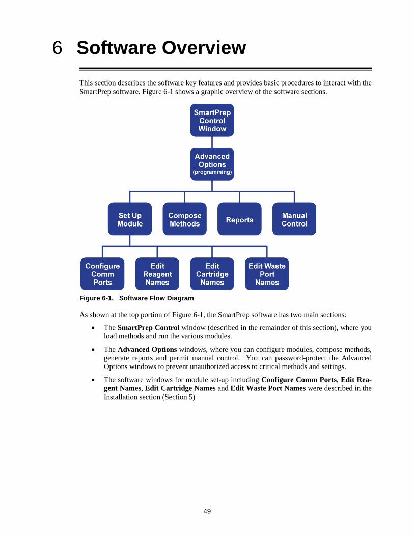
49
Software Overview 6This section describes the software key features and provides basic procedures to interact with the SmartPrep software. Figure 6-1 shows a graphic overview of the software sections.
Figure 6-1. Software Flow Diagram
As shown at the top portion of Figure 6-1, the SmartPrep software has two main sections:
• The SmartPrep Control window (described in the remainder of this section), where you load methods and run the various modules.
• The Advanced Options windows, where you can configure modules, compose methods, generate reports and permit manual control. You can password-protect the Advanced Options windows to prevent unauthorized access to critical methods and settings.
• The software windows for module set-up including Configure Comm Ports, Edit Rea-gent Names, Edit Cartridge Names and Edit Waste Port Names were described in the Installation section (Section 5)

6: Software Overview
50
6.1 SmartPrep Control Window When the SmartPrep software is opened, the SmartPrep Control window (shown below) is dis-played.
Figure 6-2. SmartPrep Control Window
The SmartPrep Control window displays:
• Total number of modules connected to the PC Controller and each status. • Specific methods being run. • The current sample and step within a method being processed. • The total time elapsed and remaining to complete the samples. • The total volume of reagents used and the volume of generated waste.
This information is presented in panels on the Control window. Notice that the panel title bars on the right side of the Control window are blue (System Status, Collection Tubes, etc.). The title bars on the left side are green (System Controls, Method Assignment, etc.). The blue-title panels display information and are used for viewing only. You input information and commands in the green-title panels.
Each panel on the Control window is described in the following sections.
In addition to the panels, notice the Sample Set Up option at the top left of the window. This op-tion enables you to save full sequences and settings so that you can recall a sequence that has been previously run.
The software version number is displayed in the title bar. Continue to check the Horizon website for new software revisions.

6.2: Module Programming Panel
51
6.2 Module Programming Panel When modules are connected to the PC Controller and powered on, graphical icons appear in the top section of the Control window. In the example below, six modules are connected. Modules 1 through 5 are in operation. Module 6 is idle and ready to be used. The grayed icons (7 and 8) in-dicate no module is connected.
Figure 6-3. Module Programming Panel
To display all information for a specific module in the Control window panels, click on the spe-cific module icon. When a module is selected, full control of that module is possible. For exam-ple, methods can be loaded to the module, and the module can be Started, Paused, Aborted, etc.
The current status of each module is indicated by a graphical icon. The status condition may be represented by any of the following.
Green icons indicate that a reagent is being moved:
Figure 6-4. Status Conditions

6: Software Overview
52
Blue icons indicate that a sample is being moved:
Figure 6-5. Status Conditions: Sample is Being Moved
Yellow icons indicate that a gas is being moved:
Figure 6-6. Status Condition: Gas is Being Moved
Additional icons are:
Figure 6-7. Additional Status Conditions

6.3: SmartPrep Extractor Error Codes & Definitions
53
6.3 SmartPrep Extractor Error Codes & Definitions The SmartPrep Extractor Software enables error tracking to prevent user error from impacting important sample SPE runs. Errors such as missing SPE cartridges, liquid sensing failure, clogging cartridges, and more, are monitored simultaneously by the software for all SmartPrep Extractor systems connected. When an error occurs, the Alert box displays the error message and associated system number with the error. Alerts can also be useful as notification messages to the laboratory technician for the sample preparation instructions or system checks to perform before clicking the Resume button to begin the run. Alerts can guide all users to operate the SmartPrep Extractor system to your requirements.
When an error occurs, the error is logged in the report generated for that run. Reports can be accessed from the Advanced Options button in the lower left corner of the main screen. Reports with errors will have a code number under the Error column.
The following error codes are configured to appear within the alert box and report:
Error Code SmartPrep Error Definition
1 Liquid Test Failed, no liquid is sensed and Liquid Sense is turned on
2 Cartridge Alignment Error, plunger is not entering car-tridge smoothly
3 SPE Column Missing, no cartridge in a carousel posi-tion used in the method set up

6: Software Overview
54
4 SPE Column Blocked, may be clogged with sample Error Other Error
6.4 Method Assignment Panel Once methods are composed and samples are ready to be run, you select methods from the dropdown list (Select Method) and assign a method(s) to a specific sample number (1 through 12).
Figure 6-8. Method Assignment Panel
Feature Description Sample Number The sample number is represented as one of the following:
Select All All positions 1 through 12 on the carousel. When the same method is to be used for all samples, click the Select All but-ton and a dialog box will open allowing you to enter the first sample number. When it is saved the second dialog box will open to allow identification of the second sample, and so on…
Pre Run Position 21 (the clean cartridge). 1 – 12 Any of the positions 1 through 12 (samples). Each sample
number has an associated color. Once a method is assigned to a sample number and a sample ID is entered, the matching color is assigned to the appropriate collection tube (as de-scribed in Section 6.6).
Post Run Position 21 (the cleaning cartridge).
mL

6.5: System Status Panel
55
Select Method Different methods can be used for the batch of samples to be processed. This dropdown list offers methods that can be assigned to specific samples.
Sample ID You can define sample IDs for each sample. When a method is assigned to a sample, you can enter a unique sample ID. A bar code reader can also be used to assign the sample ID name.
Cartridge The Cartridge size assigned to a method is displayed. Pre Run You can use Pre and Post Run operations, which would allow the module to
be automatically prepped before starting the samples and automatically cleaned at the end of the sample run. Post Run
Report Name The default report name is numerically incremented automatically and stored in the report directory.
Operator You can enter the operator’s name, which is stored with the report.
The information on this panel will be incorporated into the final report prepared by the SmartPrep Module. If mistakes are made when selecting or entering information, click the Clear button to completely clear the window of all information.
6.5 System Status Panel When a module is running and the module icon is selected on the Module Program-ming panel, detailed information of the cur-rent status is displayed. Information includes the current operation being run, the step details within the method being performed, the sample and step number be-ing performed, the elapsed time since the start of the run, the total remaining time to finish the samples, and the time of day that the module will be free. The total number of samples to be processed also is dis-played.
6.6 Collection Tubes Panel This panel associates the collection tubes assigned to each sample. If twelve samples are to be processed and each extract is to be collected in a single tube, each sample number is assigned a
specific color. This color is matched to the tube that will be used to collect the extract.
Because multiple extracts can be collected from a single sample (up to four extracts), a method is assigned to a specific sample posi-tion (1 through 12) and the software automati-cally calculates the total number of collection tubes required. The system will fill in the ap-propriate matching color. Collecting multiple fractions reduces the total number of samples
that can be processed in a single sequence. This is displayed on the Collection Tubes panel, notifying you that the maximum sample ca-pacity has been reached.
Figure 6-9. System Status Panel
Figure 6-10. Collection Tubes Panel, the Right Photo Shows the Collection Rack Filled Because Three Fractions are Collected for each Sample
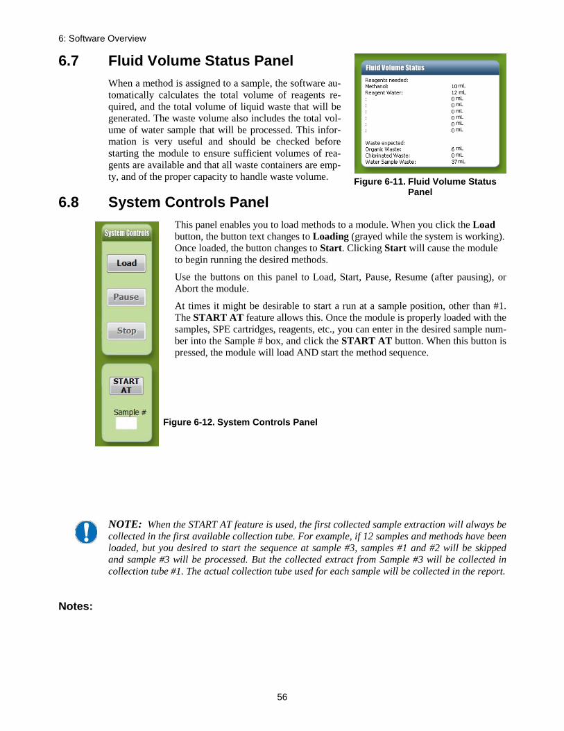
6: Software Overview
56
6.7 Fluid Volume Status Panel When a method is assigned to a sample, the software au-tomatically calculates the total volume of reagents re-quired, and the total volume of liquid waste that will be generated. The waste volume also includes the total vol-ume of water sample that will be processed. This infor-mation is very useful and should be checked before starting the module to ensure sufficient volumes of rea-gents are available and that all waste containers are emp-ty, and of the proper capacity to handle waste volume.
6.8 System Controls Panel This panel enables you to load methods to a module. When you click the Load button, the button text changes to Loading (grayed while the system is working). Once loaded, the button changes to Start. Clicking Start will cause the module to begin running the desired methods.
Use the buttons on this panel to Load, Start, Pause, Resume (after pausing), or Abort the module.
At times it might be desirable to start a run at a sample position, other than #1. The START AT feature allows this. Once the module is properly loaded with the samples, SPE cartridges, reagents, etc., you can enter in the desired sample num-ber into the Sample # box, and click the START AT button. When this button is pressed, the module will load AND start the method sequence.
NOTE: When the START AT feature is used, the first collected sample extraction will always be collected in the first available collection tube. For example, if 12 samples and methods have been loaded, but you desired to start the sequence at sample #3, samples #1 and #2 will be skipped and sample #3 will be processed. But the collected extract from Sample #3 will be collected in collection tube #1. The actual collection tube used for each sample will be collected in the report.
Notes:
Figure 6-11. Fluid Volume Status Panel
Figure 6-12. System Controls Panel
mL mL
mL mL
mL mL mL
mL mL mL
mL

57
Advanced Options 7The Advanced Options windows are used to compose methods, view reports, and permit manual control. You can password-protect the Advanced Options windows to prevent unauthorized ac-cess to critical methods and settings.
7.1 Advanced Options (Programming) To access Advanced Options windows, click the Advanced Options button in the bottom left of the Control window. The Advanced window is displayed:
Figure 7-1. Advanced Window
As described on this window, you can set up a module(s), compose/edit methods, view reports, and create custom method sequences by using a manual control process. The Set Up Module but-ton was discussed in section 5.5 during the setup of the equipment.
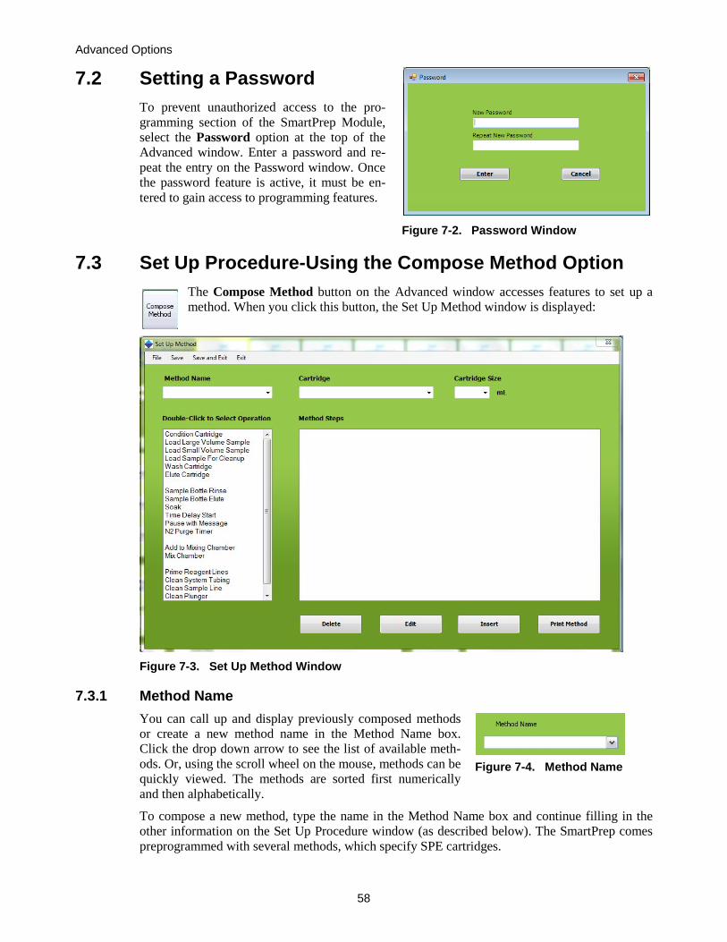
Advanced Options
58
7.2 Setting a Password To prevent unauthorized access to the pro-gramming section of the SmartPrep Module, select the Password option at the top of the Advanced window. Enter a password and re-peat the entry on the Password window. Once the password feature is active, it must be en-tered to gain access to programming features.
Figure 7-2. Password Window
7.3 Set Up Procedure-Using the Compose Method Option The Compose Method button on the Advanced window accesses features to set up a method. When you click this button, the Set Up Method window is displayed:
Figure 7-3. Set Up Method Window
7.3.1 Method Name You can call up and display previously composed methods or create a new method name in the Method Name box. Click the drop down arrow to see the list of available meth-ods. Or, using the scroll wheel on the mouse, methods can be quickly viewed. The methods are sorted first numerically and then alphabetically.
To compose a new method, type the name in the Method Name box and continue filling in the other information on the Set Up Procedure window (as described below). The SmartPrep comes preprogrammed with several methods, which specify SPE cartridges.
Figure 7-4. Method Name

7.3: Set Up Procedure-Using the Compose Method Option
59
7.3.2 Cartridge All cartridge names that are created or part of the SmartPrep software (see Section 5.5.10, Edit Cartridge Names) appear when you click the Cartridge dropdown arrow. Select the name of the cartridge to use for the method to be run. The cartridge name is stored with a method and will appear in a report when a report is generated.
7.3.3 Cartridge Size When composing a method, it is necessary to select the car-tridge size of 1, 3, or 6 mL. The cartridge size is specified on the System Configuration window. Therefore, an error mes-sage is displayed if a method specifies a cartridge size that is different from the cartridge size selected on the System Con-figuration window. Either the plunger assembly must be changed or the method modified.
7.3.4 Method Description All SPE methods on the SmartPrep Module are created using specific “operations.” The opera-tions listed on the Set Up Method window are the typical operations required by SPE cartridge methods. They are listed in the typical order they would be used in a method. However, it is pos-sible to use these operations in any order to create a custom method.
Figure 7-7. Method Description
As you look at the window, notice that the operations are separated into three groups:
• Normal SPE operations that will be used for most SPE methods (Condition Cartridge, Load Large Volume Sample, etc.).
• Operations that enable use of the mixing/reservoir chamber (Add to Mixing Chamber and Mix Chamber).
Figure 7-5. Cartridge
Figure 7-6. Cartridge Size

Advanced Options
60
• Specific operations for priming and cleaning (Prime Reagent Lines, Cleaning Sample Lines, and Clean Plunger).
At the bottom of the screen, there are four buttons:
Button Description Delete You can delete a line from a method by selecting the line and then clicking
Delete. Edit Once a method is written you can choose a line that you wish to change and
click Edit. The window where you originally created the operation is opened and you can change to the entries you wish.
Insert Once a method is written, you can select a line in the method and then click Insert to add a new blank line into the method above the selected line. This enables you to insert a new operation into the method. You can repeat this as many times as necessary to modify a method.
Print Method Once a method is written, you can print the method by clicking Print Method. A printer must be connected to the PC for this function to work and the default printer will be used.
To select an operation, double-click on the operation name. A new window will open presenting a series of entry boxes you can use to enter the desired information. This information is used to build the actual method. The following sections describe each operation and its function.
7.3.5 Condition Cartridge This operation conditions the SPE packing material with the reagents selected for the method.
Figure 7-8. Edit Condition Cartridge Method
To condition a cartridge, the following information is required:

7.3: Set Up Procedure-Using the Compose Method Option
61
Specification Description Reagent Click the drop down arrow and select the reagent. The reagent names are
stored using the Edit Reagent Names panel. Volume (mL) Enter the desired volume of reagent to condition the cartridge. Select vol-
umes from 0.1 to 999 mL. Rate (mL/min) This is the dispense rate of the reagent through the cartridge. Typical flow
rates are from 5 to 10 mL/min. (Sip rates can be different from dispense rates and are set on the System Configuration window). (0-30 mL/min)
Soak (sec) Once the reagent is introduced into the cartridge, a soak time can be used to allow the reagent to clean or activate the packing material. Typical soak times are 30 seconds to one minute. Select soak times from 1 to 3600 sec-onds (60 minutes). If no soak is desired, enter 0.
N2 Purge (sec) At the completion of the soak time, nitrogen gas can be used to purge the cartridge of all reagents. The gas pressure is adjusted on the external nitro-gen gas regulator/bracket assembly and is typically set to 10 psi. Select N2 purge times from 1 to 3600 seconds (60 minutes). If no purge is desired, leave the box blank or set the value to 0.
Liquid Sense This is used to monitor the presence of liquid in the syringe (liquid drawn from the reagent bottle). If the Liquid Sense is turned on and no liquid is sensed during a run, an Alert icon appears on the SmartPrep Control win-dow. ABORT and RESUME options are provided on the Touch Screen display.
Most methods require multiple reagents to properly condition a cartridge. Click on the next Step (such as Step 2) and a new line will appear. You can make up to 8 entrees on a single screen, but multiple Conditioning screens can be used to create a method.
NOTE: For most silica-based cartridges, methanol is used to activate the packing material. Once a silica-based cartridge has been activated, it is critically important NOT to allow the car-tridge to go dry or be exposed to air. With the SmartPrep Module, this is accomplished by setting all nitrogen purge times to 0 once the methanol has been introduced.

Advanced Options
62
7.3.6 Load Large Volume Sample This operation loads sample onto the cartridge.
Figure 7-9. Edit Load Large Volume Sample Method
The following information is required:
Specification Description Load until empty
Select this option if the entire sample is to be used. Enter a minimum volume (mL) and an estimated sample volume (mL). The liquid sensor will be used and will continue processing the sample until the sample container is empty. The actual volume of sample processed is calculated and stored in a report.
Load specific volume
If a specific volume of sample is to be processed, click this button and enter the desired value (mL) in the Volume box to the right.
Syringe Fill Pause
If too fast of a sample sip rate is used, based on the sample being processed, out-gassing could occur. If this happens, you should use a longer syringe fill pause time. After the syringe has pulled in the sample, this delay timer will cause the syringe pump to wait for the specified time before delivering the sample to the cartridge. This delay timer allows the out-gassing to occur and the water sample to “catch up” into the syringe. This delay will minimize in-troduction of small air bubbles into the cartridge.
Sample Sip Rate (mL/min)
Faster sip rates reduce the overall time to process a sample. Rates up to 50 mL/min are possible, but you will need to determine the acceptable flow rates.
Sample Delivery Rate (mL/min)
Sample delivery rates to the cartridge are a function of the cartridge used. Most cartridges have a maximum flow rate of 10 mL/min. If the rate is ex-ceeded, channeling could occur and result in low and inconsistent recoveries. Testing would need to be done to confirm that a selected flow rate is not too fast. If a flow rate is greater than the cartridge can handle, it is possible that sufficient back pressure will build up in the syringe and cause the syringe to

7.3: Set Up Procedure-Using the Compose Method Option
63
skip. If this occurs, lower the syringe delivery flow rate. (0-30 mL/min can be entered)
Syringe Dis-pense Pause
This is the time in seconds that the syringe plunger will pause on the down-stroke to compensate for any back pressure in the cartridge, due to a possible blockage. This is useful when working with dirty or viscous samples. The value is entered when creating a load operation in a method. In most cases, the default value is sufficient.
7.3.7 Load Small Volume Sample Many solid phase extraction methods use small volume sample loading onto an SPE cartridge, al-lowing impurities to pass through the cartridge and retain the compounds or analytes of interest to the packing. Any of the Waste Ports can be used as a destination to direct the liquid sample to waste. This Load Small Volume Sample operation will allow small sample volumes, up to 40 mL max, to be pulled up from any sample container and loaded onto the SPE cartridge and be di-rected to a selected waste port.
Figure 7-10. Edit Load Small Sample Volume
The following information is required.
Specification Description
Sample Volume (mL) Enter the volume in mL to be taken from the sample vessel and delivered to the cartridge
Sample Sip Rate (mL/min)
Faster sip rates reduce the overall time to process a sample. Rates up to 50 mL/min are possible, but you will need to determine the acceptable flow rates.
Syringe Fill Pause (sec)
If too fast of a sample sip rate is used, based on the sample being processed, out-gassing could occur. If this happens, you should use a longer syringe fill pause time. After the syringe has pulled in the sample, this delay timer will cause the syringe pump to wait for the specified time before delivering the sample to the cartridge. This delay timer allows the out-gassing to occur and the water sample to “catch up” into the syringe. This delay will minimize introduction of small air bubbles into the cartridge.

Advanced Options
64
Destination Choose Waste Port 1, 2 or 3 for sample waste disposal
Sample Delivery Rate (mL/min)
The sample delivery pushes the sample, from the syringe barrel, towards and into the SPE cartridge. Values in the range of 5 to 10 mL/min are typical.
Syringe Dispense Pause (sec)
This is a pause timer (in seconds), that will pause the syringe for this specified time, which will allow all liquids to come to an equi-librium pressure, before advancing to the next step.
Vent (mL) When the entire sample has been passed through the SPE car-tridge, a Vent volume push (in mL) can be used to push the sample further, to ensure the entire sample has been pushed through the SPE cartridge to waste.
N2 Purge (sec) Allows a nitrogen purge (in seconds) to be used to completely dry the cartridge, while collecting all of the sample extract in the col-lection tube.
Detailed Load Small Volume Sample Operation Example:
The following example shows how to establish a sample load of 2.2 mL over a waste port loca-tion on the SmartPrep Extractor.
• The Sample Sip Rate of 5 mL/min is optimal for lower sample volume accuracy with a non-viscous solution.
• The Sample Delivery Rate of 5 mL/min is similar to a manual vacuum elution rate of 1 drop per second.
• A Syringe Fill Pause and a Syringe Dispense Pause time of 2 seconds allows the sample to reach flow equilibration within the tubing following the Sip Rate and Dispense Rate.
• A Vent of 0.80 mL is the volume of air aspirated following the Dispense Pause time and transferred through the tubing and into the cartridge to displace the remaining sample from the lines prior to any further action. This step ensures accuracy of the 2.2 mL sample delivery volume and does not dry the cartridge prior the multiple elution steps that follow.
o Visual verification is a good first step to setting the proper vent volume, and a recommended starting value to use is 0.65 – 0.8 mL, which will account for the tubing and valve volume between the syringe and plunger. An important addi-tional consideration for the vent volume is the plunger size being used, as the volume within the plunger varies based on the size. Add the following volumes to the vent volume for best accuracy: 6 mL plunger – 0.15mL 3 mL plunger – 0.13 mL 1 mL plunger – 0.12 mL

7.3: Set Up Procedure-Using the Compose Method Option
65
1) When a method, which includes a Load Small Volume Sample operation is run, the following sequence will occur, at the start of the cleanup operation:
a. The TV3 value is read. b. The Reagent Valve (V1) rotates to the Port 12 - Vent. c. The syringe will pull in the TV3 volume of air. d. The Reagent Valve (V1) will rotate to Port 2 – connecting V1 to V2. e. The Sample Valve (V2) will rotate to the designated sample port (sample centric). f. The TV2 value is read. g. The syringe will pull in the TV2 volume, which is also pulling that volume of sample in-
to the sample line. h. The code will read all of the values, as entered on the Load Small Volume Sample opera-
tion screen and perform these steps. i. The syringe will pull in the desired volume of sample. j. The Reagent Valve (V1) will rotate to Port 1, the SPE cartridge port. k. The syringe will dispense the TV2 and the Sample Volume, but NOT the TV2 and TV3
values. The TV2 and TV3 volume of air will remain in the syringe until the ENTIRE sample has been processed.
l. When the entire sample has been processed, the TV3 value will push the remainder of the sample through the Reagent Valve (V1) and towards the SPE cartridge.
m. The Reagent Valve (V)1 will rotate to Port 2, and the excess TV2 air in the syringe will be dispensed/pushed back down the sample line.
n. The Vent and Nitrogen Purge steps will be performed if selected in the operation.
Figure 7-11. Edit Load Small Sample Method page

Advanced Options
66
NOTE: By optimizing the TV2 and TV3 values, all of the sample can be loaded onto the SPE car-tridge, while minimal excess air is directed towards the SPE cartridge. Any excess air left in the sy-ringe barrel, will automatically be directed back down the sample line.
7.3.8 Load Sample for Cleanup Solid phase extraction sample cleanup is a technique used to retain any impurities within the SPE cartridge and elute the compounds of interest during the sample load step. This technique is rou-tinely used to protect the GC and HPLC analytical columns, improve detector qualitative and quantitative responses, and help optimize signal to noise ratios. Load Sample for Cleanup will allow small sample volumes, up to 40 mL max, to be pulled up from any sample container and loaded onto the SPE cartridge for collection. Note that using this operation will collect the load volume into a fraction in the Collection Tube Rack. See image below for the Load Sample for Cleanup operation in the list of SmartPrep operations.
The Load Sample for Cleanup operation will collect the liquid passing through the SPE cartridge into one of the four collection tubes, which are located in the Collection Tube Rack. The follow-ing sequence of events is used for the Load Sample for Cleanup operation:
Specification Description
Sample Volume (mL)
The Sample Volume (in mL) to be processed, up to 40 mL max
Sample Sip Rate (mL/min)
The sample sip pulls the sample into the syringe barrel. Values in the range of 5 to 20 mL/min are typical
Syringe Fill Pause (sec)
This is a pause timer (in seconds) such that if outgassing occurs, or a vis-cous sample is being processed, that the syringe will pause for the speci-fied time, before advancing to the next step. A typical value would be a 2 to 3 second Pause.
Destination Collection Tube 1, 2, 3, or 4. Note that this is the first, second, third, and fourth available collection tube for that sample.
Sample Delivery The sample delivery pushes the sample, from the syringe barrel, towards
Figure 7-12. Edit Load Sample for Cleanup Method
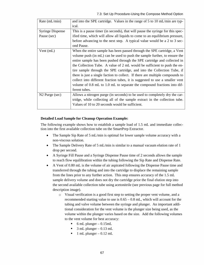
7.3: Set Up Procedure-Using the Compose Method Option
67
Rate (mL/min) and into the SPE cartridge. Values in the range of 5 to 10 mL/min are typ-ical.
Syringe Dispense Pause (sec)
This is a pause timer (in seconds), that will pause the syringe for this spec-ified time, which will allow all liquids to come to an equilibrium pressure, before advancing to the next step. A typical value would be a 2 to 3 sec-ond Pause.
Vent (mL) When the entire sample has been passed through the SPE cartridge, a Vent volume push (in mL) can be used to push the sample further, to ensure the entire sample has been pushed through the SPE cartridge and collected in the Collection Tube. A value of 2 mL would be sufficient to push the en-tire sample through the SPE cartridge, and into the Collection Tube, if there is just a single faction to collect. If there are multiple compounds to collect into different fraction tubes, it is suggested to use a smaller vent volume of 0.8 mL to 1.0 mL to separate the compound fractions into dif-ferent tubes.
N2 Purge (sec) Allows a nitrogen purge (in seconds) to be used to completely dry the car-tridge, while collecting all of the sample extract in the collection tube. Values of 10 to 20 seconds would be sufficient.
Detailed Load Sample for Cleanup Operation Example:
The following example shows how to establish a sample load of 1.5 mL and immediate collec-tion into the first available collection tube on the SmartPrep Extractor.
• The Sample Sip Rate of 5 mL/min is optimal for lower sample volume accuracy with a non-viscous solution.
• The Sample Delivery Rate of 5 mL/min is similar to a manual vacuum elution rate of 1 drop per second.
• A Syringe Fill Pause and a Syringe Dispense Pause time of 2 seconds allows the sample to reach flow equilibration within the tubing following the Sip Rate and Dispense Rate.
• A Vent of 0.80 mL is the volume of air aspirated following the Dispense Pause time and transferred through the tubing and into the cartridge to displace the remaining sample from the lines prior to any further action. This step ensures accuracy of the 1.5 mL sample delivery volume and does not dry the cartridge prior the final elution step into the second available collection tube using acetonitrile (see previous page for full method description image).
o Visual verification is a good first step to setting the proper vent volume, and a recommended starting value to use is 0.65 – 0.8 mL, which will account for the tubing and valve volume between the syringe and plunger. An important addi-tional consideration for the vent volume is the plunger size being used, as the volume within the plunger varies based on the size. Add the following volumes to the vent volume for best accuracy: 6 mL plunger – 0.15mL 3 mL plunger – 0.13 mL 1 mL plunger – 0.12 mL

Advanced Options
68
1) Any other SmartPrep operations can be added before and after the Load Sample for Cleanup op-eration to create an SPE method. For example, the Conditioning operation could be used to first prepare the cartridge for the sample to be cleaned, while the Wash operation, might be used to remove any impurity before collecting the second fraction.
2) When a method, which includes a Load Sample for Cleanup operation is run, the following se-quence will occur, at the start of the cleanup operation:
a. The TV3 value is read. b. Reagent valve (V1) rotates to the Port 12 - Vent. c. The syringe will pull in the TV3 volume of Vent (air). d. V1 will rotate to Port 2 – connecting V1 to sample valve (V2). e. V2 will rotate to the designated sample port (for the sample to be processed). f. The TV2 value is read. g. The syringe will pull in the TV2 volume, which will pull that volume of sample into the
sample line. h. The software code will read all of the values, as entered on the Load Sample for Cleanup
operation screen and perform these steps. i. The syringe will pull in the desired volume of sample. j. V1 will rotate to Port 1, the SPE cartridge port. k. The syringe will dispense the TV2 and the Sample Volume, but NOT the TV2 and TV3
values. The TV2 and TV3 volume of air will remain in the syringe until the ENTIRE sample has been processed (up to a maximum of 40 mL for the Load Sample for Cleanup operation).
l. When the entire sample has been processed, the TV3 value will push the remainder of the sample through V1 and towards the SPE cartridge.
m. V1 will rotate to Port 2, and the excess TV2 air in the syringe will be dispensed/pushed back down the sample line. This syringe push will also push the entire sample remaining in the tubing, back into the sample container.
n. The Vent and Nitrogen Purge steps will be performed if selected in the operation.
Figure 7-13. Edit Load Sample for Cleanup with Typical Values

7.3: Set Up Procedure-Using the Compose Method Option
69
NOTE: By optimizing the TV2 and TV3 values, all of the sample can be loaded onto the SPE car-tridge, while minimal excess air is directed towards the SPE cartridge. Any excess air left in the sy-ringe barrel, will automatically be directed back down the sample line.
7.3.9 Wash Cartridge This operation washes the SPE packing material with the reagents selected for the method. Wash-ing is used after the sample has been processed to return the cartridge packing material to a neu-tral pH state and/or to remove any residual sample still left on the cartridge.
Figure 7-14. Edit Wash Cartridge Method
The following information is required:
Specification Description Reagent Click the drop down arrow and select the reagent. The reagent names are
stored using the Edit Reagent Names panel (see Section 5.5.9, Edit Reagent Names,).
Volume Enter the desired volume of reagent to wash the cartridge. Select volumes from 0.1 to 999 mL.
Rate (mL/min) This is the dispense rate of the reagent through the cartridge. Typical flow rates are from 5 to 10 mL/min. (0-30 mL/min allowed)
Soak (sec) Once the reagent is introduced into the cartridge, a soak time can be used to allow the reagent to clean or activate the packing material. Select soak times from 1 to 3600 seconds (60 minutes). For washes, typically no soak times are required. If no soak is desired, enter 0.
N2 Purge (sec) Once all of the wash reagents have been delivered to the cartridge, nitrogen gas can be used to purge the cartridge of all reagents. The gas pressure is adjusted on the external nitrogen gas regulator/bracket assembly and is typi-cally set to 10 psi. Select N2 purge times from 1 to 3600 seconds. If no purge is desired, leave the box blank or set the value to 0.
Liquid Sense This is used to monitor the presence of liquid in the syringe (liquid drawn from the reagent bottle). If the Liquid Sense is turned on and no liquid is sensed during a run, an Alert icon appears on the SmartPrep Control win-dow. ABORT and RESUME options are provided on the Touch Screen display.

Advanced Options
70
7.3.10 Elute Cartridge This operation elutes the SPE packing material with the reagents (directly from the reagent bot-tles or the Mixing Chamber) selected for the method.
Figure 7-15. Edit Elute Cartridge Method
The following information is required:
Specification Description Reagent Click the drop down arrow and select the reagent. The reagent names are
stored using the Edit Reagent Names panel (see Section 5.5.9, Edit Reagent Names). It is possible to use the Mixing Chamber as the source of the Elut-ing Reagents.
Volume Enter the desired volume of reagent to elute the cartridge. Select volumes from 0.1 to 35 mL.
Rate (mL/min) This is the dispense rate of the reagent through the cartridge. Typical flow rates are from 5 to 10 mL/min. (Sip rates can be different from dispense rates and are set on the System Configuration window, as described in Sec-tion 5.5.4, Reagents section).
Destination All of the eluting reagent can be collected in one tube, or sent to four sepa-rate tubes. Select the destination from the drop down list. This is handy fea-ture for fractionation and/or method development.
Soak (sec) Once the reagent is introduced into the cartridge, a soak time can be used to allow the reagent to elute the packing material. Typical soak times are 30 seconds to one minute. Select soak times from 1 to 3600 seconds (60 minutes). For washes, typically no soak times are required. If no soak is de-sired, enter 0.
N2 Purge (sec) At the completion of the soak time, nitrogen gas can be used to help elute all reagents into the collection tube. The gas pressure is adjusted on the external nitrogen gas regulator/bracket assembly and is typically set to 10 psi. Select N2 purge times from 1 to 3600 seconds. If no purge is desired, leave the box blank or set the value to 0.
Liquid Sense This is used to monitor the presence of liquid in the syringe (liquid drawn

7.3: Set Up Procedure-Using the Compose Method Option
71
from the reagent bottle). If the Liquid Sense is turned on and no liquid is sensed during a run, an Alert icon appears on the SmartPrep Control win-dow. ABORT and RESUME options are provided on the Touch Screen display.
7.3.11 Sample Bottle Rinse This operation is available only when the optional Rinse Reagent Kit is installed. If the kit is present, a specified volume of re-agent is directed to a “holding loop,” which in turn is sprayed into the sample bottle us-ing high pressure nitrogen gas. The nitro-gen is delivered through nitrogen valve N2P2 at approximately 15 to 30 psi.
Figure 7-16. Edit Sample Bottle Rinse Method
The following information is required:
Specification Description Reagent Click the drop down arrow and select the reagent. The reagent names are
stored using the Edit Reagent Names panel (see Section 5.5.9, Edit Reagent Names).
Volume (mL) Enter the desired volume of reagent to rinse the sample bottle. The maxi-mum volume is 6 mL per bottle rinse operation.
VENT The vent is used to move the rinse reagent completely into the holding loop. Volumes of 2-3 mL are sufficient.
Spray Time (sec)
This is the time that N2P2 will be energized and spray the reagent into the sample bottle. Typical times of 5 to 10 seconds are adequate.
Liquid Sense This is used to monitor the presence of liquid in the syringe (liquid drawn from the reagent bottle). If the Liquid Sense is turned on and no liquid is sensed during a run, an Alert icon appears on the SmartPrep Control win-dow. ABORT and RESUME options are provided on the Touch Screen dis-play.

Advanced Options
72
7.3.12 Sample Bottle Elute This operation is used when sample bottles are manually rinsed with reagent, or when the option-al Rinse Reagent Kit is installed. In either case, the reagent delivered to the bottle, either manual-ly or automatically, is removed from the bottle and delivered to the cartridge.
When the reagent is pulled from the sample bottle, the reagent is first delivered to the mixing chamber. This is done to deliver the reagent as a consistent liquid aliquot and to minimize the amount of air delivered to the cartridge.
Figure 7-17. Edit Sample Bottle Elute Method
The following information is required:
Specification Description
Volume Enter the desired volume of reagent to be pulled from the sample bottle. It is better to use a larger volume than the original amount of the reagent sprayed into the sample bottle, as the entire reagent needs to be into the Mixing Chamber. It is suggested that the user verify this volume experimentally prior to running samples.
Destination Click the drop down arrow and select the vessel in which the extract is to be collected. You can collect up to 4 fractions.
Volume Enter the desired volume of reagent to be pulled from the Mixing Chamber. Use a slightly larger volume than the original amount of the reagent moved to the Mixing Chamber, to be delivered to the cartridge.
Sip Rate This is the rate at which the reagent will be pulled from the Mixing Cham-ber. (0-30 mL/min accepted)
Delivery Rate This is the rate the reagent will be passed through the cartridge. (0-30 mL/min accepted)
Soak (sec) This is the time (in seconds) used to soak the cartridge. (0-3600 sec) N2 Purge (sec) This is the amount of time that nitrogen will be passed through the cartridge.
(0-3600 sec)
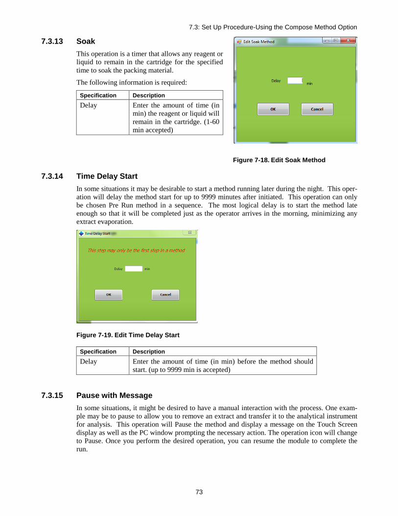
7.3: Set Up Procedure-Using the Compose Method Option
73
7.3.13 Soak This operation is a timer that allows any reagent or liquid to remain in the cartridge for the specified time to soak the packing material.
The following information is required:
Specification Description Delay Enter the amount of time (in
min) the reagent or liquid will remain in the cartridge. (1-60 min accepted)
Figure 7-18. Edit Soak Method
7.3.14 Time Delay Start In some situations it may be desirable to start a method running later during the night. This oper-ation will delay the method start for up to 9999 minutes after initiated. This operation can only be chosen Pre Run method in a sequence. The most logical delay is to start the method late enough so that it will be completed just as the operator arrives in the morning, minimizing any extract evaporation.
Figure 7-19. Edit Time Delay Start
Specification Description Delay Enter the amount of time (in min) before the method should
start. (up to 9999 min is accepted)
7.3.15 Pause with Message In some situations, it might be desired to have a manual interaction with the process. One exam-ple may be to pause to allow you to remove an extract and transfer it to the analytical instrument for analysis. This operation will Pause the method and display a message on the Touch Screen display as well as the PC window prompting the necessary action. The operation icon will change to Pause. Once you perform the desired operation, you can resume the module to complete the run.

Advanced Options
74
Figure 7-20. Edit Wait for Operator Method
The following information is required:
Specification Description Message to Operator
Enter the message to be displayed. A maximum of 30 characters can be used.
7.3.16 N2 Purge Timer Similar to the nitrogen purge available with the conditioning, wash, and elute operations, this nitrogen purge timer will purge low pressure nitrogen through the cartridge for the specified time.
The following information is required:
Specification Description Delay Enter the time (in min)
to purge low pressure nitrogen through the cartridge.
7.3.17 Add to Mixing Chamber This operation allows a specified volume of any one of the 8 reagents to be directed to the mixing chamber so reagent mixtures can be prepared. The mixing chamber has a capacity of 10 mL and should not be exceeded.
Figure 7-21. Edit N2 Purge Timer Method

7.3: Set Up Procedure-Using the Compose Method Option
75
Figure 7-22. Edit Add to Mixing Chamber Method
The following information is required:
Specification Description Reagent Click the drop down arrow and select the reagent. Reagent names are stored
using the Edit Reagent Names panel (see Section 5.5.9, Edit Reagent Names).
Volume (mL) Enter the desired volume of reagent to add to the mixing chamber. Rate (mL/min) This is the dispense rate of the reagent into the mixing chamber. Typical
flow rates are from 5 to 10 mL/min. (Sip rates can be different from dis-pense rates and are set on the System Configuration window, as described in Section 5.5.4, Reagents). (0-30 accepted)
Liquid Sense This is used to monitor the presence of liquid in the syringe (liquid drawn from the reagent bottle). If the Liquid Sense is turned on and no liquid is sensed during a run, an Alert icon appears on the SmartPrep Control win-dow. ABORT and RESUME options are provided on the Touch Screen display.
7.3.18 Mix Chamber This operation allows any reagent in the mixing chamber to be mixed a specified number of cycles and at a set mixing rate.
The following information is required:
Specification Description
Cycles Click the box and enter the total number of mixing intervals to use.
Volume (mL) Enter the desired volume of the reagent to mix.
Delivery Rate (mL/min)
This is the mixing rate the sy-ringe will use to thoroughly mix the chamber.
Figure 7-23. Edit Mix Chamber Method Page

Advanced Options
76
7.3.19 Prime Reagent Lines This operation allows any residual air to be removed from the reagent lines, and to easily clean the reagent lines when switch-ing to a different reagent.
The following information is required:
Specification Description
Reagent Click the arrow next to the reagent that is to be primed. The reagent names are stored using the Edit Reagent Names panel (refer to Section 5.5.9, Edit Reagent Names).
Volume (mL) Enter a value between 0 and 6 mL of reagent to flush through the tub-ing. All reagents will be sent through the cleaning cartridge, which is located in carousel position #21.
Rate (mL/min) This is the dispense rate of the reagent through the tubing. Typical flow rates are from 30 to 50 mL/min. (Sip rates can be different from dispense rates and are set on the System Configuration window, as described in Section 5.5.4, Reagents).
Liquid Sense This is used to monitor the presence of liquid in the syringe (liquid drawn from the reagent bottle). If the Liquid Sense is turned on and no liquid is sensed during a run, an Alert icon appears on the SmartPrep Control window. ABORT and RESUME options are pro-vided on the Touch Screen display.
7.3.20 Clean System Tubing The purpose of Clean System Tubing operation is to clean the system tubing following either the Load Sample for Cleanup or the Load Small Volume Sample operations to remove traces of sam-ple in the tubing between Reagent Valve (V1) and Sample Valve (V2) and to clean out all residu-al sample in the syringe before the next sample begins. Smaller volume loading of samples for EPA, USDA, AOAC, and FDA methods typically measure for concentrations of compounds at a low level, and this operation is very useful in properly cleaning of tubing before processing each sample by allowing up to eight different solvents to be used for a gradient cleaning procedure.
Figure 7-24. Prime Reagent Lines
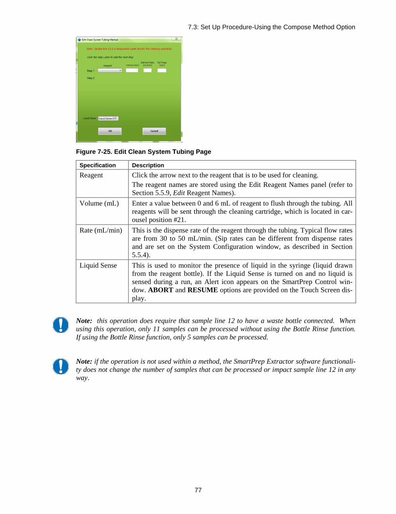
7.3: Set Up Procedure-Using the Compose Method Option
77
Figure 7-25. Edit Clean System Tubing Page
Specification Description Reagent Click the arrow next to the reagent that is to be used for cleaning.
The reagent names are stored using the Edit Reagent Names panel (refer to Section 5.5.9, Edit Reagent Names).
Volume (mL) Enter a value between 0 and 6 mL of reagent to flush through the tubing. All reagents will be sent through the cleaning cartridge, which is located in car-ousel position #21.
Rate (mL/min) This is the dispense rate of the reagent through the tubing. Typical flow rates are from 30 to 50 mL/min. (Sip rates can be different from dispense rates and are set on the System Configuration window, as described in Section 5.5.4).
Liquid Sense This is used to monitor the presence of liquid in the syringe (liquid drawn from the reagent bottle). If the Liquid Sense is turned on and no liquid is sensed during a run, an Alert icon appears on the SmartPrep Control win-dow. ABORT and RESUME options are provided on the Touch Screen dis-play.
Note: this operation does require that sample line 12 to have a waste bottle connected. When using this operation, only 11 samples can be processed without using the Bottle Rinse function. If using the Bottle Rinse function, only 5 samples can be processed.
Note: if the operation is not used within a method, the SmartPrep Extractor software functionali-ty does not change the number of samples that can be processed or impact sample line 12 in any way.
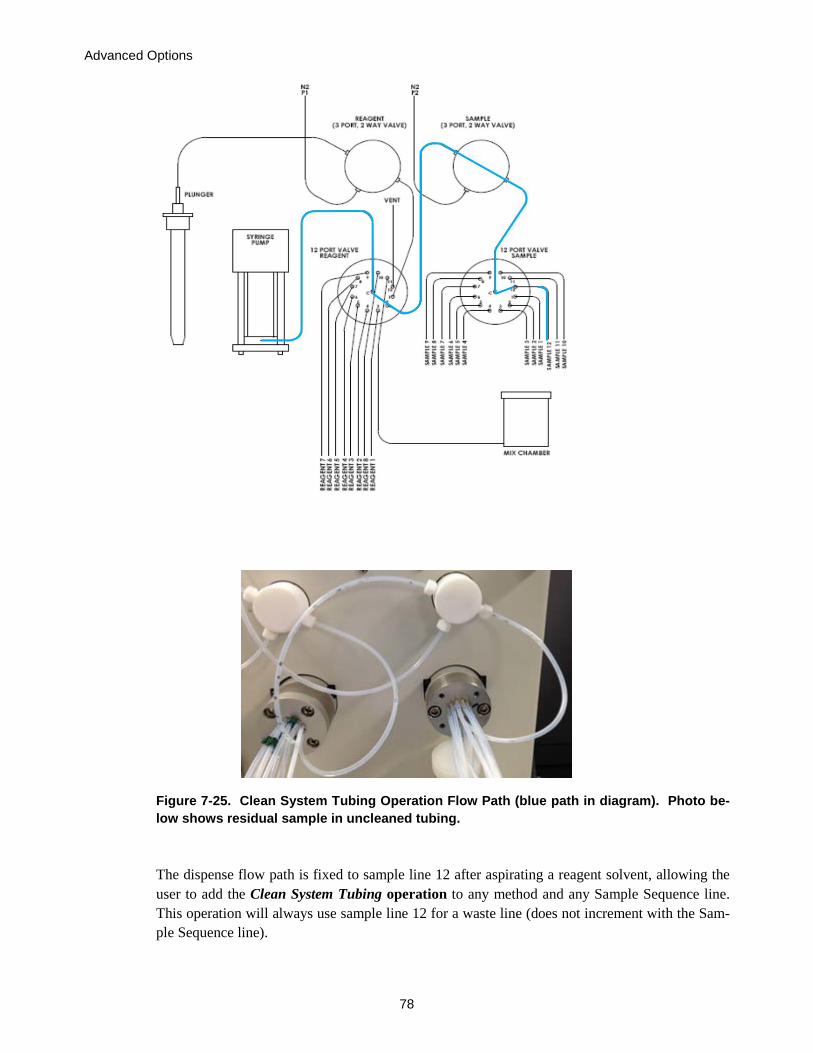
Advanced Options
78
Figure 7-25. Clean System Tubing Operation Flow Path (blue path in diagram). Photo be-low shows residual sample in uncleaned tubing.
The dispense flow path is fixed to sample line 12 after aspirating a reagent solvent, allowing the user to add the Clean System Tubing operation to any method and any Sample Sequence line. This operation will always use sample line 12 for a waste line (does not increment with the Sam-ple Sequence line).

7.3: Set Up Procedure-Using the Compose Method Option
79
Clean System Tubing Programming and Description of Operation:
The flow path for the Clean System Tubing operation will always use sample line 12 for a waste line and follows the list of operational steps listed below:
• Carousel homes to cleaning cartridge and plunger goes into cartridge • Valve 1 switches to selected reagent position • Syringe aspirates reagent X at volume Y • Valve 2 switches to position 12 • Syringe dispenses reagent X at volume Y and speed Z • N2 time, if any occurs • Repeat above for as many steps as user programmed
Example of Using the Clean System Tubing Operation:
When using the Clean System Tubing opera-tion, it is important to remember that this should be used in conjunction with the Clean Plunger operation to ensure full system cleaning of all tubing on the SmartPrep Extractor. An example is provided in Figure 7-27 showing a Clean Plunger program that might be used with a Clean System Tubing program. These steps should be included at the end of the running SPE method to ensure that the full system tub-ing is cleaned following SPE and prior to pro-cessing the next sample. If you prefer to use the
nitrogen purge instead of an air vent, this is an available option within both operations.
Figure 7-26. Example of Clean System Tubing Program
Figure 7-27. Example of Clean Plunger and Clean System Tubing Methods that can be used together

Advanced Options
80
7.3.21 Clean Sample Lines This operation allows each of the sample lines to be easily cleaned. Once this method is created, it is simply assigned to the specific sample lines to be cleaned.
Figure 7-28. Edit Clean Sample Line Method
The following information is required:
Specification Description Reagent Click the drop down arrow and select the reagent. The reagent names are
stored using the Edit Reagent Names panel (see Section 5.5.9, Edit Reagent Names).
Volume (mL) Enter the desired volume of reagent to flush through the sample line tubing. The sample lines must be placed into a suitable waste to collect the entire waste reagent.
Rate (mL/min) This is the dispense rate of the reagent through the tubing. Typical flow rates are from 10 to 20 mL/min. (Sip rates can be different from dispense rates and are set on the System Configuration window, as described in Section 5.5.4, Reagents).
Liquid Sense This is used to monitor the presence of liquid in the syringe (liquid drawn from the reagent bottle). If the Liquid Sense is turned on and no liquid is sensed during a run, an Alert icon appears on the SmartPrep Control win-dow. ABORT and RESUME options are provided on the Touch Screen dis-play.

7.3: Set Up Procedure-Using the Compose Method Option
81
7.3.22 Clean Plunger This operation allows the plunger assembly to be cleaned.
Figure 7-29. Edit Clean Plunger Method
The following information is required:
Specification Description
Reagent Click the drop down arrow and select the reagent. The reagent names are stored using the Edit Reagent Names panel (see Section 5.5.9, Edit Reagent Names).
Volume (mL) Enter the desired volume of reagent to flush through the plunger. All rea-gents will be sent through the cleaning cartridge, which is located in carousel position #21.
Rate (mL/min) This is the dispense rate of the reagent through the plunger. Typical flow rates are from 10 to 20 mL/min. (Sip rates can be different from dispense rates and are set on the System Configuration window, as described in Sec-tion 5.5.4, Reagents).
Soak (sec) This is a timer that can be set if it is desired to soak and condition the plung-er and associated tubing. If no soak is desired, enter 0.
N2 Purge (sec) This is a timer to activate the nitrogen gas and gently remove all reagents from the tubing. If no purge is desired, leave the box blank or set the value to 0.
Liquid Sense This is used to monitor the presence of liquid in the syringe (liquid drawn from the reagent bottle). If the Liquid Sense is turned on and no liquid is sensed during a run, an Alert icon appears on the SmartPrep Control win-dow. ABORT and RESUME options are provided on the Touch Screen dis-play.

Advanced Options
82
7.4 View and Print Reports—Using the Reports Option The Reports button on the Advanced Options window accesses features to view and print a report. When you click this button, the View and Print Reports window is dis-played:
Figure 7-30. View and Print Reports Window
At the completion of each run, a Report is generated and stored in the Reports directory: C:\Horizon TechnologySP\SmartPrep\Reports
To view a report, click Browse All or Open Most Recent in the menu bar. Then, select the Re-port you are looking for. The report will appear on the screen or open with the appropriate soft-ware. The report can be Viewed or Printed.
The Report displays the following information:
• The directory pathway where the report is stored • The file name • The module number on which the samples were run • The operator’s name (if entered before the run was started) • The size of the cartridge used • Yes or no, if the Bottle Rinse option was used • The values for TV1, TV2 and TV3 • The start date and time for the run • All pertinent information about the samples and the run
o Sample ID
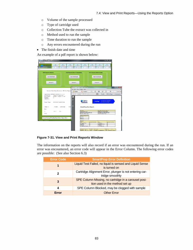
7.4: View and Print Reports—Using the Reports Option
83
o Volume of the sample processed o Type of cartridge used o Collection Tube the extract was collected in o Method used to run the sample o Time duration to run the sample o Any errors encountered during the run
• The finish date and time An example of a pdf report is shown below:
Figure 7-31. View and Print Reports Window
The information on the reports will also record if an error was encountered during the run. If an error was encountered, an error code will appear in the Error Column. The following error codes are possible: (See also Section 6.3)
Error Code SmartPrep Error Definition
1 Liquid Test Failed, no liquid is sensed and Liquid Sense is turned on
2 Cartridge Alignment Error, plunger is not entering car-tridge smoothly
3 SPE Column Missing, no cartridge in a carousel posi-tion used in the method set up
4 SPE Column Blocked, may be clogged with sample Error Other Error

Advanced Options
84
7.5 Using Manual Control The Manual Control button on the Advanced window accesses features to trouble-shoot problems using hardware commands. When you click this button, the following window is displayed:
Figure 7-3. Manual Control Window
Manual Control operations are described in Section 10.
7.6 Advanced Programming Features 7.6.1 How to Determine the TV Value
The procedure used to determine the TV values uses Manual Control, which is explained in Sec-tion 10. The procedure to use Manual Control to check and adjust the TV values is described in section 5.5.8.
7.6.2 How to Estimate Sample Volume Calculation Variables One very unique SmartPrep feature is the ability to quite accurately estimate the total volume of the processed sample. This ability eliminates the operator from manually marking the sample bot-tle, using the sample, refilling the bottle to the mark with tap water, and pouring this into a large graduated cylinder to determine the starting volume. This manual operation is time consuming and, because visually reading a mark or graduation line is very subjective, this operator interac-tion is prone to significant errors. This section describes the procedure to properly calibrate the SmartPrep to more accurately estimate the actual sample volume processed.
Background Explanation In order for the SmartPrep to calculate the water sample volume, some key information is needed. The required information is listed below:
1. Load operation

7.6: Advanced Programming Features
85
This is the time (in seconds) when the module Touch Screen display first shows the Load op-eration (start of the sample processing step), and when the display advances to the next op-eration (end of the sample processing step) – typically a Wash operation. This time value is automatically calculated by the SmartPrep.
2. Overhead Time for Load Step This is the time (in seconds) when the module Touch Screen display first shows the Load op-eration (start of the sample processing step), and when the syringe first begins to pull the sample into the syringe. Typically, before the actual sample is pulled into the syringe, reagent water is first pulled into the syringe and sent down the sample line to remove all residual air. This is to provide better chemistry. This operation can range from 25 to 36 seconds, based on which sample sip tubes are used. The value is manually calculated by the user and is entered into the Utilities screen. See below for more information on how to calculate this value.
3. Syringe Fill Pause This is the time (in seconds) that the syringe plunger will pause on the upstroke to allow the liquid sample to fill the syringe. This is a useful feature when working with viscous samples, liquids that outgas, or if fast sip rates are used. The value is entered when creating a Load op-eration in a method.
4. Sample Sip Rate This is the rate (in mL/min) at which the sample will be pulled into the syringe barrel. The value is entered by the user when creating a Load operation in a method.
5. Sample Delivery Rate This is the rate (in mL/min) at which the sample will be pushed through the SPE cartridge. The value is entered by the user when creating a Load operation in a method.
6. Syringe Dispense Pause This is the time (in seconds) that the syringe plunger will pause on the down stroke to com-pensate for any back pressure in the cartridge, due to a possible blockage. This is useful when working with dirty or viscous samples. The value is entered when creating a Load op-eration in a method. The default value is usually sufficient.
7. Overhead Time per Syringe Stroke This is the time (in seconds) for the 12 port Reagent Valve, V1, to first rotate to the sample port (port 2) and, once the syringe is filled, to rotate back to the SPE cartridge (port 1). Typi-cal times range between 0.9 and 1.3 seconds, based on the method. The value is manually en-tered by the user into the Utilities screen.
8. Calibration Offset This is a value (in mL) that is automatically added to the software algorithm. The offset value is needed as the liquid sensor can be positioned anywhere between 0.1 and 5.9 mL, and this position must be accounted for. Typical offset values are -8 to -13, and are entered by the us-er into the Utilities screen, following the directions in Step 14, following.
From the System Configuration screen, open the Utilities screen (shown below). Enter the values shown in the Load Volume Computation section into the Utilities screen on your PC. Click the Save and Exit button. The values just entered are a good approximation for the actual values needed, so the next section will explain how to determine the correct values to enter.

Advanced Options
86
Figure 7-34. Utilities Window
To help determine the most accurate values (not often required) to enter, use the following exam-ple.
Example The following example shows how to set the proper values when running samples of approxi-mately 100 mL.
Step 1: Create the following Calculate Sample Volume method (as shown below).
Figure 7-35. Method Description Window
Step 2: See Section 11.6 to position the Liquid Sensor at the 3 mL position.
Step 3: Make sure you have 2 stopwatches available.
Step 4: Fill a bottle with 100 mL of tap water. Use a graduated cylinder, or weigh the sample to 100.0 g for better accuracy.

7.6: Advanced Programming Features
87
Step 5: Insert sample line #1 into the bottle and make sure the line stays at the bottom. This can be ac-complished by using the stainless steel sip tubes. It helps to use the SmartPrep Sample Bottle Racks because the rack will tilt the bottle so all of the liquid can be removed.
Step 6: Load the Calibrate Sample Volume method into sample slot #1. After the method has loaded, look at the bottom of the main screen and note the Report Name/Number. Then click Start.
Step 7: Watch the Touch Screen display and, when the word Load appears on the top line, start both stopwatches.
Step 8: Closely watch the syringe plunger as it pulls up Reagent Water (the TV2 value) and directs this down sample line #1.
Step 9: When the Syringe reaches the bottom of its stroke, be ready. When the syringe quickly begins to pull up, stop one of the stopwatches and record this value. This time is the Overhead Time for Load Step.
Step 10: Allow the run to continue. The syringe will continue to pump the water until the Liquid Sensor determines that there is no liquid present. When you visually see that no liquid is in the barrel, be ready with the second stopwatch because the Load operation will end at the bottom of this last sy-ringe stroke.
Step 11: Watch the Touch Screen display and, when the word Load is replaced by Clean Sample Lines, stop the second stopwatch. Record this time.
Step 12: At the completion of the run, click the Advanced Options button, followed by clicking the Re-ports button. In the menu bar, click Open and find the report name and number just run. In this report you will find the estimated volume of the sample just processed.
Step 13: Compare the estimated calculated volume against the actual volume of the sample (100 mL).
Step 14: In the Utilities screen, compare the Overhead Time for Load Step value with your first recorded time. If the times are different, enter in the time you recorded.
Step 15: If the reported volume is greater than the actual 100 mL volume, enter the difference as a nega-tive value into the Calibration Offset.
Step 16: Click the Save and Exit button.
The SmartPrep module is now calibrated for the samples. If you make a change to the module’s configuration, it is recommended to repeat this calibration exercise.
7.6.3 How to use the SmartPrep Module without Being Connected to the PC Another useful feature of the SmartPrep Module is that once a method sequence has been loaded to the module and the module started, the PC can be disconnected and the SmartPrep will run this method sequence over and over again. This is be a very useful feature for labs that plan to only run a specific set of methods or samples on a specific SmartPrep Module.
This allows greater flexibility by allowing the SmartPrep to be placed in various locations where it might not be suitable to locate a PC. However, it is important to keep in mind that once the module is disconnected from the PC, reports will not be generated and estimated volumes cannot be calculated. The user must decide which is more important: free standing operation or reports and estimated volume calculations. The following instructions will explain how to use this free standing feature.
Step 1: With the PC connected to a module, load the desired method(s) and start the module.
Step 2: Once the module has started, close the SmartPrep operating software.
Step 3: Disconnect the USB cable to the module that is to operate free standing.
Step 4: Reopen the SmartPrep software and continue working with the other modules.

Advanced Options
88
Step 5: At the end of the run, the free standing module will retain the method sequence in memory. Therefore, simply pressing the Start button on the Touch Screen display to start the same method sequence again. The method sequence is held in a nonvolatile memory, such that even if the module is turned off and back on, the same method sequence is retained. The method sequence can only be changed by reconnecting the PC and downloading a new sequence.
7.6.4 How to Use the Sample Set Up Sequence Feature If similar samples are to be processed in multiple batches, a convenient way to enter information is to use the Sample Set Up Sequence. Follow these steps to use the sequence feature.
Step 1: Load the method(s) to the sample slots.
Step 2: In the SmartPrep Control window menu bar, click on Sample Set Up and click Save As.
Step 3: A new window will open. In the File Name box, enter a method sequence name to be saved. Do not change the file extension from the .SMP. Once the desired file name has been entered, click Save.
Step 4: The method sequence has now been saved. To confirm this, click the Sample Set Up again. Click Open and the saved sequence will appear.
The method sequence feature makes it easy to load a method(s) to all 12 samples and quickly start the module.

7.6: Advanced Programming Features
89
Notes:

Composing Methods
90
Composing Methods 8Before a chemistry procedure is composed as a SmartPrep Module method, it is important to first think through the chemistry and the steps that need to be performed, to ensure that the proper chemistry will take place and in the correct sequence.
8.1 Overview of Composing a Sample Method As an example, assume you have a volume of green colored water and you want to filter 0.5 mL of sample and end up with the yellow and blue pigment separated and in different collection tubes. To perform this chemistry you will:
• Select the cartridge packing. For this simple test, a 6-mL C18 cartridge would be a good choice.
• Since C18 must be properly conditioned and prepared for the water sample, use methanol and reagent water to prepare the cartridge.
• When the cartridge is being conditioned, it is critical that the cartridge not go dry. After the water sample has been passed through the cartridge, use a reagent water wash to re-move water sample from the cartridge. Follow this with nitrogen gas to remove as much of the residual water as possible.
• To elute the blue pigment off the cartridge packing, use a reagent that has a greater chem-ical affinity for the blue pigment than does the C18 packing. Methanol is an ideal rea-gent. Since it will be used as a conditioning reagent, it can also be used as the eluting reagent.
With this information, you will be ready to compose a “Food Color” method. The method will comprise the following steps. Each step is detailed in Section 8.2 below.
• Condition the cartridge with methanol and allow a sufficient soak time to activate the C18.
• Condition the cartridge with reagent water to remove the methanol from the packing. Traces of methanol left in the packing will allow the pigment of interest to pass through the packing.
• Load the desired volume of water sample (0.5 mL) into the cartridge.
• Wash the cartridge with reagent water to remove excess colored water.
• Purge the cartridge with nitrogen gas to remove residual water.
• Elute the cartridge with 2 mL aliquots of methanol and collect all extracts into a single collection tube.
8.2 Composing a Sample Method, Part 1: Configuring the Module Configure the SmartPrep Module to run this method. Follow these steps.
Step 1: Click on the module icon that is to be configured.
Step 2: On the SmartPrep Control window, click the Advanced Options button.
Step 3: Click the Set Up Module button. Refer to Figure 8-1 for the following steps.

8.2: Composing a Sample Method, Part 1: Configuring the Module
91
Step 4: On the System Configuration window, use the drop down arrows under the Waste Port section and select Organic Waste for port #1 and Water Sample Waste for port #2.
Step 5: Under the Reagents section, select Methanol as reagent 1 and Reagent Water as reagent 2.
Step 6: Use the default sip speed of 30 mL/min for both.
Step 7: Select the waste ports for each reagent: Organic Waste for methanol and Water Sample Waste for reagent water. Even though the third waste port will not be used in this method, it must be set up and can be assigned Chlorinated Waste.
Step 8: Select the appropriate plunger size for your system (6 mL plunger size, indicated here).
Step 9: Select No Bottle Rinse in the Bottle Rinse Configuration section.
Step 10: Set the Tubing Volumes TV1 to 0.0 (Volume between syringe and inlet port on V1) and TV2 to 2.1 (Volume between sample line inlet and V1), respectively. Set TV3 to 0.2. If the 5-inch sip tube is used, enter a value of 2.75; if the 10-inch sip tube is used enter 3.0 mL for TV2. If the tubing values are inaccurate the separation will be affected. If the color separation is not true, the procedure in section 5.5.8 should be followed to optimize and verify the values before rerunning the method.
The System Configuration window should look like the one below.
Figure 8-1. System Configuration Window
Step 11: Click Save and Exit to save these settings and exit the System Configuration window.
The module is now configured to run the Food Color method.

Composing Methods
92
8.3 Composing a Sample Method, Part 2: Composing a Prime Reagent Lines Method Before the Food Color method is run, it is necessary to purge all residual air from the reagent lines. If the air is not removed prior to running the sample, the cartridge will not be conditioned properly, and random and low recoveries would result. Therefore, you must compose a Prime Reagent Lines method using the same reagents (methanol and reagent water) that will be used in the method.
Step 1: On the Advanced Options window, click the Compose Method button. The Setup Up Method window is displayed, as shown below. This is where you compose and/or modify all methods. Follow the remaining steps to compose the Prime Reagent Lines method.
Figure 8-2. Set Up Procedure Window
Step 2: Click in the Method Name box. Type the name: Green Prime Reagent Lines
Step 3: In the Cartridge drop down box, select the Cleaning Cartridge.
mL

8.3: Composing a Sample Method, Part 2: Composing a Prime Reagent Lines Method
93
Step 4: In the Cartridge Size drop down box, select a 6 mL cartridge. See the figure below.
Figure 8-3. Method Name, Cartridge, and Cartridge Size
Step 5: Operations are available for composing a method, as shown on the left side of the window. Double-click on Prime Reagent Lines operation.
Figure 8-4. Prime Reagent Lines Operation
The Prime Reagent Lines window is displayed.
Figure 8-5. Prime Reagent Lines Window
Refer to Figure 8-6 for the following steps.
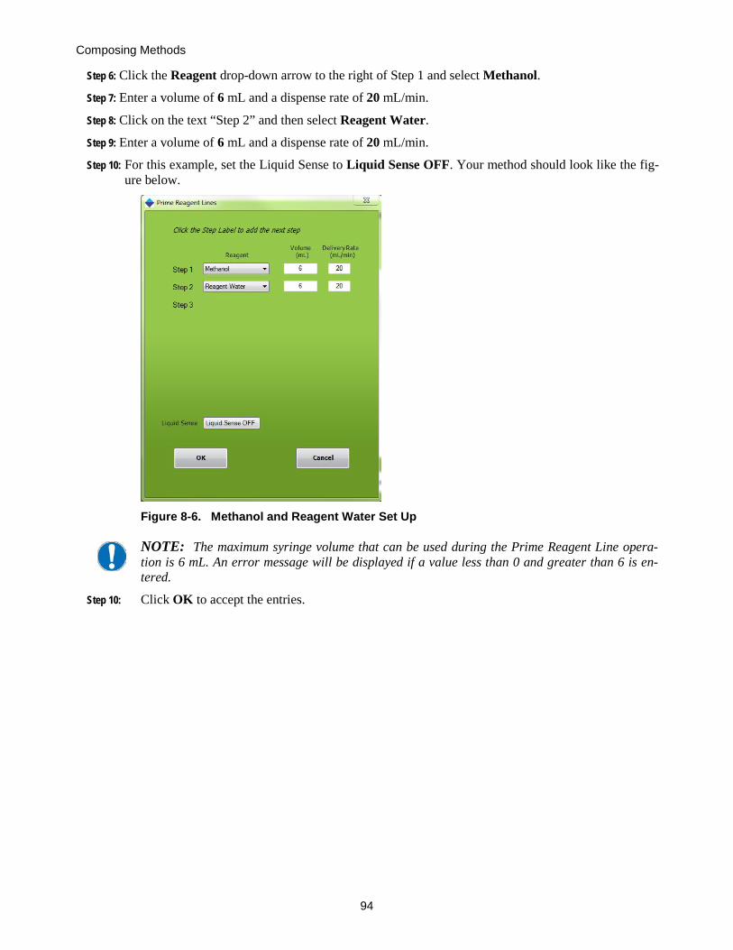
Composing Methods
94
Step 6: Click the Reagent drop-down arrow to the right of Step 1 and select Methanol.
Step 7: Enter a volume of 6 mL and a dispense rate of 20 mL/min.
Step 8: Click on the text “Step 2” and then select Reagent Water.
Step 9: Enter a volume of 6 mL and a dispense rate of 20 mL/min.
Step 10: For this example, set the Liquid Sense to Liquid Sense OFF. Your method should look like the fig-ure below.
Figure 8-6. Methanol and Reagent Water Set Up
NOTE: The maximum syringe volume that can be used during the Prime Reagent Line opera-tion is 6 mL. An error message will be displayed if a value less than 0 and greater than 6 is en-tered.
Step 10: Click OK to accept the entries.

8.4: Composing a Sample Method, Part 3: Composing a Procedure
95
In the Method Steps section of the Set Up Method window, you will see the methods you are composing:
Figure 8-7. Procedure Description
Step 11: Click Save and Exit to save this method.
8.4 Composing a Sample Method, Part 3: Composing a Procedure Follow these steps to compose the Food Color method to extract food color from a sample.
Step 1: On the Advance Options window, click the Compose Method button. The Setup Up Method window is displayed.
Step 2: Click in the Method Name box. Type in the name: Food Color Method.
Step 3: In the Cartridge drop down box, select the SPE cartridge to be used. For this method, select a C18 cartridge.
Step 4: In the Cartridge Size drop down box, select a 6 mL cartridge.
Figure 8-8. Method Name, Cartridge, and Cartridge Size
Step 5: In the Operation section of the window, double click on Wash Cartridge.

Composing Methods
96
Figure 8-9. Wash Cartridge selection
Step 6: The Edit Wash Cartridge window opens.
Figure 8-10. Edit Wash Cartridge Window
Step 7: Click the Reagent drop-down arrow to the right of Step 1 and select Methanol.
Step 8: Enter a volume of 6 mL, a dispense rate of 30 mL/min and a soak time of 5 sec.
Step 9: Click on the text “Step 2” and select Vent.
Step 10: Enter a volume of 6 mL at a dispense rate of 30 mL/min.
Step 11: In the Operation section of the window, double-click on Prime Reagent Lines

8.4: Composing a Sample Method, Part 3: Composing a Procedure
97
Figure 8-11. Prime Reagent Lines Operation Choice
Step 10: Click the reagent drop-down to the right of Step 1 and select VENT.
Step 11: Enter a volume of 2 mL at a delivery rate of 30 mL/min. The screen should look as shown in the figure.
Figure 8-12. Prime Reagent Lines with VENT
Step 12: In the Operation section of the window, double-click on Condition Cartridge.

Composing Methods
98
Figure 8-13. Condition Cartridge Operation
The Edit Condition Cartridge Method window is displayed.
Figure 8-9. Edit Condition Cartridge Method Window
Step 13: Click the Reagent drop-down arrow to the right of Step 1 and select Methanol.
Step 14: Enter a volume of 3 mL, a dispense rate of 10 mL/min, a soak time of 10 seconds, and a nitrogen purge time of 0.
Step 15: Click on the text “Step 2” and select Reagent Water.
Step 16: Enter a volume of 1.5 mL, a dispense rate of 30 mL/min, a soak time of 0 seconds, and a nitrogen purge time of 0.
Step 17: Click on the text “Step 3” and select Reagent Water to add another Reagent Water conditioning step. Two Reagent Water steps are being used to effectively remove all methanol from the car-tridge packing.
Step 18: Enter a volume of 1.5 mL, a dispense rate of 10 mL/min, a soak time of 0 seconds, and a nitrogen purge time of 0.

8.4: Composing a Sample Method, Part 3: Composing a Procedure
99
Step 19: For this example, set the Liquid Sense to Liquid Sense OFF.
Your window should appear as shown in Figure 8-10.
With these steps, a Conditioning sequence has been composed, whereby 3 mL of methanol will be delivered to the cartridge and allowed to soak the C18 for 10 seconds. This is a shorter time than would normally be used for most chemistry, but the goal of this exercise is to show how SPE methods are created. After the 10 seconds soak time, 1.5 mL of reagent water will be introduced with the purpose of removing the methanol from the cartridge. There is no soak time for this step. Notice that no nitrogen purge is used; therefore, the cartridge remains immersed in liquid and not allowed to go dry.
Figure 8-10. Reagents for a Conditioning Sequence
Step 20: Click OK to accept these entries. You will see the entries just made in the Set Up Method win-dow.

Composing Methods
100
Step 21: The next step is to load the sample on to the cartridge and we have several choices on how to ac-complish this step. Since we are loading a small sample, 0.5 mL, we can choose between using a clean-up procedure, where the waste for the loading step is collected or a load small sample step where the waste for the loading step is discarded. In this case, because the color is a diagnostic it would be helpful to see if any color passes through the cartridge and is not retained. Therefore we will use the Load Sample for Cleanup operation.
Figure 8-11. Load Sample Operation
The Edit Load Sample Method window is displayed.
Figure 8-12. Edit Load Sample Method Window with Entries
Step 22: Per the method requirements for this example, you will process a specific volume: 0.5 mL of sample. Therefore, click the Sample Volume option and enter 0.5 mL.
Enter the sample sip rate of 10 mL/min and Syringe Fill Pause of 2 sec.
Step 23: At the bottom of the window, enter the collection location for the waste sample (1st collection tube), a Sample Delivery Rate of 5 mL/min, Syringe Dispense Pause of 2 seconds. At higher sample sip rates, the syringe fill pause allows any out-gassing to occur before the syringe begins

8.4: Composing a Sample Method, Part 3: Composing a Procedure
101
to pump the sample through the SPE cartridge. The Syringe Dispense Pause is the time that the syringe plunger will pause on the down stroke to compensate for any back pressure in the car-tridge, due to a possible blockage. The default is sufficient in most cases.
Your window should appear as shown in Figure 8-13.
Step 24: Click OK to accept these entrees.
In the Description section of the Set Up Method window, you will see more of the operations you are composing.
Figure 8-13. Method Steps through Sample Loading
Step 25: The next operation is to elute the cartridge with methanol. Double-click the Elute Cartridge op-eration and enter information as shown below. When done, click OK.
Figure 8-14. Edit Elute Cartridge Method Window

Composing Methods
102
Step 26: For this particular Food Color Method, only 0.5 mL of sample will be withdrawn from the origi-nal sample container. Because we want to remove all residual sample from the line and clean the system before introducing the next sample, a Clean Sample Line operation will be used. Follow the steps below to use this operation.
Step 27: Double-click on the Clean Sample Lines operation and enter the information as shown in the window below.
Figure 8-15. Edit Clean Sample Line Method Window
Step 28: The window below shows the completed method, which clearly indicates each step that will be followed when this method is run. If a printer is connected to the PC, click the Print Procedure button for a hardcopy of the method.
Step 29: Save this method, by clicking Save and Exit.
Figure 8-16. Completed Set Up Procedure
The Food Color Demo method is now complete.

8.5: Preparing to Run Methods
103
8.5 Preparing to Run Methods Now that the module is configured and the Food Color and the Prime Reagent Lines methods are composed, the SmartPrep Module must be prepared to run these methods. Follow the steps below to prepare a module.
Step 1: Locate the cleaning cartridge. This is an empty cartridge that contains frits, but no packing mate-rial. Place this cleaning cartridge into position #21 on the carousel. You can manually rotate the carousel in either direction to bring position #21 to the front. To do so, gently turn the carousel in either direction.
Step 2: Locate a C18 SPE cartridge. Place this cartridge in position #1 on the carousel. You can manually rotate the carousel in either direction to bring position #1 to the front.
Step 3: Locate two suitable containers to hold the methanol and reagent water reagents. Fill each contain-er with the proper reagent. Set these containers on the table to the right of the module.
Step 4: On the 12-port valve to the right of the syringe pump, the Reagent Valve (V1), identify reagent lines 1 and 2. There are small numbered bands on each line. Place line 1 into the methanol con-tainer and line 2 into the reagent water container. Make sure the ends of the lines are completely immersed in the reagents.
Step 5: On the 12-port valve closest to the back edge of the module, the Sample Valve (V2), identify Sample Line 1. Place this line into a container with approximately 50 mL of tap water. To this tap water, add approximately one drop of green food color. Gently swirl the container to mix the food color.
NOTE: In order to keep the small FEP tubes completely immersed in the sample, sip tubes are available as an option. If these were purchased with the system, carefully press the end of sample line 1 onto the barb fitting attached to the end of one of the stainless steel sip tubes. Place this sip tube into the food color water sample.
Step 6: On the back side of the module, identify waste lines 1 and 2. Place line 1 into an empty container (this will be for the organic waste–methanol). Place line 2 into an empty container (this will be for the reagent water waste and the water sample waste).
Figure 8-17. Front and Side View
Sample Valve (V2) 12-Port Switching Valve
Nitrogen Gas Valves
Touch Screen Display
Cartridge Plunger
Power Switch
Cartridge Carousel
Collection Tube Rack
Syringe Pump/Liquid Sensor
Reagent Valve (V1) 12-Port Switching Valve
Reagent Mixing Chamber / Reservoir

Composing Methods
104
Figure 8-18. Back Side View
USB Comm Port
Labels
N2P1 – Low Pressure Nitrogen Gas Inlet Fitting
N2P2 – High Pressure Nitrogen Gas Inlet Fitting
Power: 24 VDC Power Receptacle
Expansion: Future Comm Port
Waste Port Fittings W1, W2, W3 and Waste Block Drain

8.5: Preparing to Run Methods
105
Step 7: Locate the collection tube rack and place a tube into rack position 1. Slide this rack into the rack tray located in the front of the module. The tray will “key” into position.
Step 8: If the power switch is turned off, turn it on now. The power switch is located on the front below the Touch Screen display.
Step 9: On the SmartPrep Control window, click the icon for module 1. These icons are located in the top part of the window. The icon for the selected module is outlined in yellow.
Figure 8-19. Select Module 1
Step 10: On the Method Assignment panel, click the Select Method down arrow and select the method named Green Prime Reagent Lines.
Step 11: In the Sample Number column, click the Pre Run button. This will load the Green Prime Reagent Lines method into the Pre Run slot.
Figure 8-20. Load the Green Prime Reagent Lines Method into the Pre Run Slot
Step 12: Click the Select Method down arrow and select Food Color Method.
Click the in the Sample Number column. The Enter Sample ID window will appear, asking for the sample ID name. This is a name that will be used as a reference ID only. You can ignored this for now, or enter a name. If a bar code reader is used, scan the barcode for the sam-ple ID now.
mL

Composing Methods
106
Figure 8-21. Enter Sample ID Window
Step 13: Click Save. The Food Color Method will be assigned and used to process sample 1.
Figure 8-22. Load the Food Color Method into the Sample 1 Slot
A useful feature is the ability to see the steps of the method(s) that have been loaded and are about to run. Simply click the method name and a new window will appear, showing the details of the method. This window can be dragged off to the side for continual reference while the method is running.
Step 14: To prepare the green food color sample that will be separated using this method the following de-tails are necessary. Although most C18 cartridges will work using these conditions, we used JT Baker C18 cartridges and others may require slight adjustments to the parameters for the best color separation.
Step 15: To prepare the colored water solution for separation follow the directions:
mL
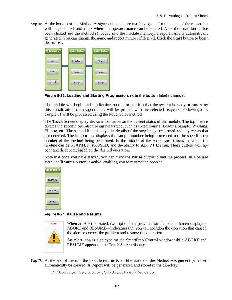
8.5: Preparing to Run Methods
107
Step 16: At the bottom of the Method Assignment panel, are two boxes; one for the name of the report that will be generated, and a box where the operator name can be entered. After the Load button has been clicked and the method(s) loaded into the module memory, a report name is automatically generated. You can change the name and report number if desired. Click the Start button to begin the process.
Figure 8-23. Loading and Starting Progression, note the button labels change.
The module will begin an initialization routine to confirm that the system is ready to run. After this initialization, the reagent lines will be primed with the selected reagents. Following this, sample #1 will be processed using the Food Color method.
The Touch Screen display shows information on the current status of the module. The top line in-dicates the specific operation being performed, such as Conditioning, Loading Sample, Washing, Eluting, etc. The second line displays the details of the step being performed and any errors that are detected. The bottom line displays the sample number being processed and the specific step number of the method being performed. In the middle of the screen are buttons by which the module can be STARTED, PAUSED, and the ability to ABORT the run. These buttons will ap-pear and disappear, based on the desired operation.
Note that once you have started, you can click the Pause button to halt the process. In a paused state, the Resume button is active, enabling you to resume the process.
Figure 8-24. Pause and Resume
When an Alert is issued, two options are provided on the Touch Screen display—ABORT and RESUME—indicating that you can abandon the operation that caused the alert or correct the problem and resume the operation.
An Alert icon is displayed on the SmartPrep Control window while ABORT and RESUME appear on the Touch Screen display.
Step 17: At the end of the run, the module returns to an Idle state and the Method Assignment panel will automatically be cleared. A Report will be generated and stored in the directory:
C:\Horizon TechnologySP\SmartPrep\Reports

Composing Methods
108
This completes running your first method on the SmartPrep Module.
The method is successful if the colors are clearly separated into blue and yellow and the solution collected in collection location is clear, without color.
You are now ready to create and run your own methods. During the software installation, copies of several useful cartridge methods were loaded into the directory:
C:\Horizon TechnologySP\SmartPrep\Factory Methods
These methods are available for use or can be modified. See Section 7 for more information.
Notes:

109
Summary of Normal Operations 9and Recommendations
9.1 Best Practices 9.1.1 General
Optimal automated SPE with the SmartPrep Extractor is a result of keeping the system properly maintained, with sample and reagent lines clean. Optimal operation can often reduce the frequency of service calls, which allows more productive and regular use of the SmartPrep Extractor over an ex-tended period of time between routine maintenance procedures.
Samples and reagents may have a viscous nature, have an acidic or basic pH, or be organic solvents within the alkane family. In all of these cases, it is important to properly run a Pre Run Method prior to running the SPE sample methods and conclude the day or set of samples with a Post Run Method. Below are some examples of Pre Run and Post Run Methods that can be programmed and run using the SmartPrep Extractor to keep the system running optimally.
9.1.2 Proper Acid and Base Usage When using solutions which may form salt crystals when combined, the user should ensure that they meet the following parameters:
• The Plunger, Syringe, and System Tubing should be washed with an intermediary reagent, such as water, to reduce the probability of crystal formation within the instrument.
• The fluid pathways within the system should be flushed using Reagent Water to ensure that the Acid or Base is removed or diluted within the system.
• Extreme pH solutions should be sent to different Waste Ports in the System Set Up screen. This prevents the formation of salts within the waste lines as well as preventing unwanted re-actions from occurring in the waste container.
In-Line Prefiltering: It is highly recommended that all samples make use of in-line prefilters to ensure that the internal fluid pathways of the SmartPrep do not become occluded and the valves are not damaged.
9.1.3 Pre Run Methods The purpose of establishing and running a Pre Run Method is to get the SmartPrep Extractor ready to run samples accurately by running a series of operations within a method to wet the solvent lines and sample contact materials, as well as remove air bubbles. These methods are run just once before the samples are started. Common operations to use in Pre Run Methods:
• Clean Plunger • Prime Reagent Lines
Considerations when determining the order of solvents to use for the above operations will be solubil-ity of the analytes of interest, miscibility of the reagents/solvents, as well as reagent compatibility with the first step in the SPE method that will run the samples. A good rule of thumb when consider-ing volume to use when priming is as follows:

9: Summary of Normal Operations and Recommendations
110
• Prime 3X the volume of the reagent tubing when the system has been sitting unused follow-ing a Post Run Method to clean and dry the lines. Run this once to establish the system from a rested state.
• Prime with 2X the tubing volume on a daily basis to remove air bubbles from the lines prior to running SPE samples.
Examples of Pre Run Methods: A) Run after the SmartPrep has been sitting clean and dry over a weekend is shown below and B) Run after the SmartPrep has been used the day before. Additional cleaning is performed when the system has sat for longer periods of time to ensure it is ready for the best performance.
9.1.4 After Sample Cleanup Methods The purpose of establishing and running an After Sample Cleanup Method is to properly clean the system tubing (reagent and sample) and all sample contact materials on the SmartPrep Extractor us-ing a series of operations to let the system sit in a clean and dry state over a weekend or longer until it is ready to run again. Common operations to use in after sample cleanup methods:
• Clean Plunger • Prime Reagent Lines • Clean sample lines with a gradient of solvents prior to purging samples lines with air or nitrogen • Clean reagent lines with a gradient of solvents prior to purging reagent lines with air or nitrogen
Considerations when determining the or-der of solvents to use for the above op-erations will be solubility of the analytes of interest, miscibility of the rea-gents/solvents, as well as reagent compat-ibility with the first step in the SPE method that will run the samples. A good rule of thumb when considering volume to use is the same as used for priming in the Pre Run Methods:
Figure 9-1. Examples of Pre Run methods. A is run after sitting and B is run after the system was used the day before
A
B
Figure 9-2. Example after sample cleanup method
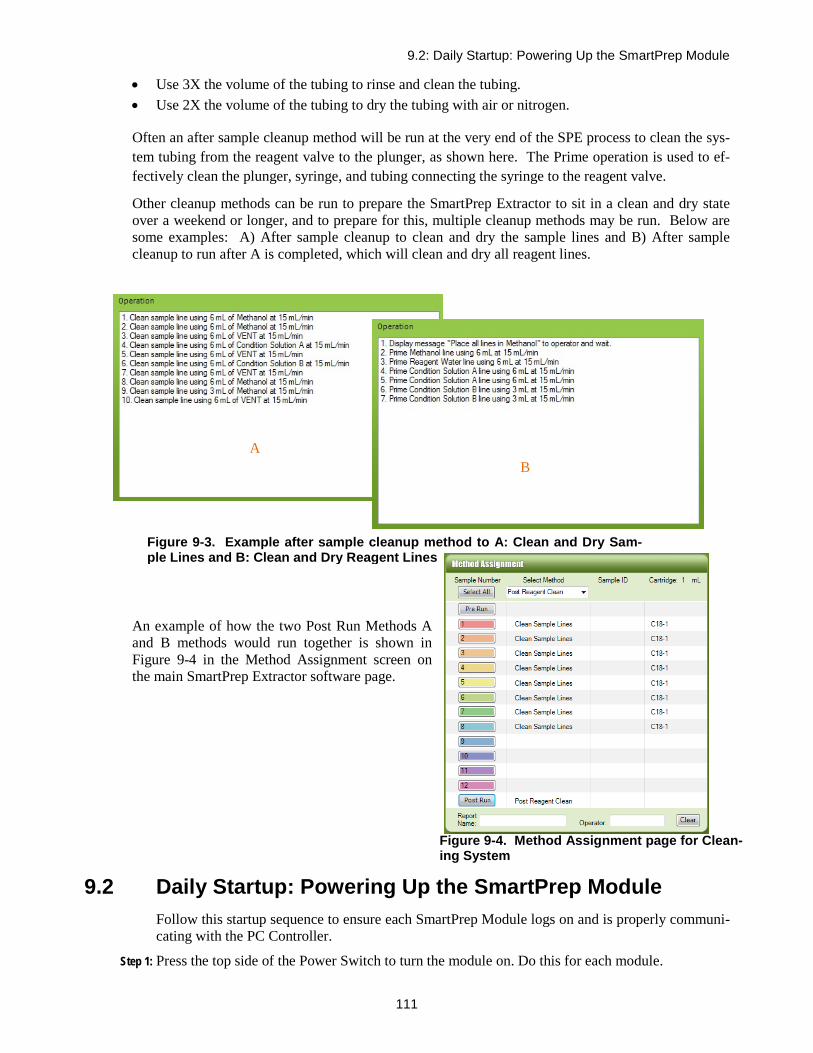
9.2: Daily Startup: Powering Up the SmartPrep Module
111
• Use 3X the volume of the tubing to rinse and clean the tubing. • Use 2X the volume of the tubing to dry the tubing with air or nitrogen.
Often an after sample cleanup method will be run at the very end of the SPE process to clean the sys-tem tubing from the reagent valve to the plunger, as shown here. The Prime operation is used to ef-fectively clean the plunger, syringe, and tubing connecting the syringe to the reagent valve.
Other cleanup methods can be run to prepare the SmartPrep Extractor to sit in a clean and dry state over a weekend or longer, and to prepare for this, multiple cleanup methods may be run. Below are some examples: A) After sample cleanup to clean and dry the sample lines and B) After sample cleanup to run after A is completed, which will clean and dry all reagent lines.
An example of how the two Post Run Methods A and B methods would run together is shown in Figure 9-4 in the Method Assignment screen on the main SmartPrep Extractor software page.
9.2 Daily Startup: Powering Up the SmartPrep Module Follow this startup sequence to ensure each SmartPrep Module logs on and is properly communi-cating with the PC Controller.
Step 1: Press the top side of the Power Switch to turn the module on. Do this for each module.
Figure 9-3. Example after sample cleanup method to A: Clean and Dry Sam-ple Lines and B: Clean and Dry Reagent Lines
A B
Figure 9-4. Method Assignment page for Clean-ing System

9: Summary of Normal Operations and Recommendations
112
Step 2: Start the SmartPrep operating software and observe that each module icon appears and displays the Idle state.
Step 3: The SmartPrep Module is now ready for use.
Step 4: Select and load all methods to be used, as described in Section 8.5.
9.3 Daily Startup: Preparing the Module Before using the SmartPrep Module(s) to run samples, perform the following:
Step 1: Inspect all reagent containers to make sure the containers are filled with fresh reagent.
Step 2: Empty all waste containers and make sure they are of the capacity to contain all wastes from the samples to be processed.
Step 3: Load a cleaning cartridge of the correct size into position #21 on the carousel.
Step 4: Load the appropriate number of SPE cartridges (and of the correct size) into the carousel.
Step 5: Insert the sample lines into the samples to be processed.
Step 6: Select and load all methods to be used, as described in Section 8.5, starting on page 103.
WARNING Avoid eye injury by wearing safety glasses when working with reagents. Always work with ex-treme care when handling reagents.
9.4 Priming the Reagent Lines Before samples are processed, it is necessary to purge the reagent lines of all residual air. If any air is present in the reagent lines, the desired volume of reagent will not be delivered. Follow the steps below to prime the reagent lines.
Step 1: Make sure the reagent containers are filled with the reagents to be used.
Step 2: Make sure the reagent lines are immersed in the reagent and near the bottom of the containers.
Step 3: If a Prime Reagent Lines method does not exist, create one.
Step 4: Open the Prime Reagent Lines method. Confirm that all the reagents to be used for the analytical method are specified in the Prime Reagent Lines method.
Step 5: Load and Run the Prime Reagent Lines method. Run it a second time, if needed, until all air is removed from the lines.
A message will display on the screen if a reagent is not available (configured in the setup).
9.5 Cleaning the Sample Lines After highly contaminated or dirty samples are run, it might be necessary to run a method to re-move any contamination from the sample lines at the end of the run. Follow these steps to clean the lines.
Step 1: Compose a method using the Clean Sample Line operation. The method should be to dispense 5 mL of reagent at a rate of 10 mL/min and use a 5 second nitrogen purge. This method will pull the reagent from the reagent container and dispense the reagent down each sample line.
Step 2: Place a cleaning cartridge in position 21 on the carousel.

9.6: Preventing Carryover
113
Step 3: Insert all of the sample lines to be cleaned into an empty sample container, or bottle. As nitrogen will be purged through these lines, make sure the lines are constrained to remain within the bottle/ container.
Step 4: Refer to the Clean Sample Lines operation (described on page 76) and clean each of the lines.
9.6 Preventing Carryover Carryover is the type of contamination that occurs when some of the sample remains in the tub-ing and can be carried over to the next sample. The fluid path between Reagent Valve (V1), the Sample Valve (V2), the syringe pump, and the plunger assembly transport both reagents and samples. Therefore, carryover should be checked when running highly contaminated samples. The best way to clean the module is to run a series of reagents, starting with the weakest reagent and working toward the strongest organic reagent. Use the following procedure to determine if carryover exists.
Step 1: Run a blank sample (one that contains no analytes) and confirm there is no background contami-nation coming from the SmartPrep Module.
Step 2: Run a sample that contains a high concentration of analytes.
Step 3: Run another blank sample.
Step 4: Analyze the blank sample for carryover of analytes.
Remember, the carryover measurement is a test of the entire analytical process not just the SmartPrep Module. Therefore, it is important that all manual parts of the analytical process, liq-uid transfer steps, glassware, evaporation steps, etc. be tested and confirmed that they are not the source of carryover. If carryover is found, this is an indication that the analytical method needs to be optimized further, as the background is coming from the original sample. Optimize the method by adding more reagent rinses, or internal cleaning steps, and ensure all liquids are being trans-ferred to the designated collection tube.
If contamination is found, then an appropriate cleaning procedure should be developed including but not limited to the following: -Pre-run cleaning steps -Plunger and Sample or System Line Cleaning within the extraction method -Post-Run cleaning steps -Development of a Cleaning Se-quence which contain only methods that are designed to clean the system. For assistance, contact Horizon Technology's Support Center.
9.7 Daily Shut Down Procedure At the end of the day, or over a weekend, it is advisable to purge the sample lines with reagents. Start with the weakest organic reagent and work toward the strongest organic reagent. Once this is done, turn off the nitrogen gas and continue with the steps below.
IMPORTANT: You must follow the following shut down sequence. First, exit out of the SmartPrep software. Upon exiting the software, information from the PC Controller is written back to each module. If the module is shut down first, this information will not be downloaded to the modules.
Step 1: Exit out of the SmartPrep operating software program.
Step 2: As the SmartPrep software shuts down, the software writes calibration and service hour infor-mation back to each module. The writing process is fast, but allow 1 to 2 seconds before power-ing down the modules.
Step 3: Press the bottom side of the Power Switch to turn the module off. Do this for each module.

9: Summary of Normal Operations and Recommendations
114
9.8 Extended Shut Down Procedure If the SmartPrep Modules are not going to be used for an extended period of time, it is advisable to flush all reagent lines with methanol. Do not use reagent water, as standing water in the lines could allow bacterial growth especially in warm, humid climates. Rust also could form in the brazed fittings of the 12-port valve.
Step 1: Remove the reagent lines from the reagent containers and place the lines into a beaker of metha-nol.
Step 2: Purge all of the reagent lines using a Prime Reagent Lines method.
Step 3: Remove the lines from the methanol container and rerun the Prime Reagent Lines method to air dry the lines.
The module is now ready for long term storage.
NOTE: When storing in freezing temperatures, all liquid should be blown out of the module us-ing nitrogen. The tubing line connected to the syringe pump can be temporarily removed and used to facilitate access to any trapped liquid.

9.8: Extended Shut Down Procedure
115
Figure 9-5. Summary of the Start-Up and Shut-Down Procedures.

9: Summary of Normal Operations and Recommendations
116
Notes:

117
Manual Control Operations 10The Manual Control capability of the SmartPrep Module is primarily designed to allow a trained Service Engineer full control to test and troubleshoot the module. The Manual Control also al-lows an experienced user to create a sequence of steps for method development, and/or to deter-mine the optimal set of conditions for a specific chemistry.
WARNING Use of Manual Control by-passes the normal safe operation of the SmartPrep, which could cause damage to the unit.
When you click the button on the Advanced Options window, the following window is displayed:
Figure 10-1. Manual Control Window
Listed in the table below, are 19 steps that you can use individually, or to create a sequence of steps. Each step is described below. The last step requires knowledge of Cavro code language and should only be used by a trained Service Engineer.
Click on Check Valves before running a sequence of steps entered in the box on Figure 10-1 to ensure they are rotating properly. If an error message appears, shut down the software and power down the SmartPrep module. Remove the side cover of the instrument and rotate the valve by hand to release the sticking. Replace the side panel and press Check Valves again to ensure the problem is solved. See Figure 10-2 for a description of where the valve is and a small rotation is needed. It is unlikely that this procedure will have to be performed. The Check Valves operation should relieve any potential sticking.

10: Manual Control Operations
118
Step Description
Valve 1 Home Rotates the Reagent Valve (V1) to its home position. Once the valve has been homed, all other port positions can be found. Therefore, it is rec-ommended to “home” the valve at the beginning of any sequence.
Valve 2 Home Rotates the Sample Valve (V2) to its home position. Once the valve has been homed, all other port positions can be found. Therefore, it is rec-ommended to “home” the valve at the beginning of any sequence.
Syringe Home Moves the syringe plunger to the down position (zero volume). Slide Home Moves the collection rack slide mechanism to its home position, which is
back and to the middle. Carousel Home Rotates the carousel to its home position, so all other carousel positions
can be found. Plunger Pos Allows the Cartridge Plunger to be moved to one of two positions: Up or
Down. Note: If no other method was run or action has been performed on the SmartPrep Extractor prior to entering manual control, home the carousel and then move the plunger down.
Valve 1 Pos Once the Reagent Valve (V1) 1 has been homed, entering a value of 1 through 12 will cause the valve to be rotated to the desired port position.
Valve 2 Pos Once the Sample Valve (V2) has been homed, entering a value of 1 through 12 will cause the valve to be rotated to the desired port position.
Syringe Speed Controls the speed of the syringe pump. Values of 0.1 to 250 mL/min can be entered.
Syringe Pos Indicates the position of the syringe plunger (in mL) from the bottom plug. Values from 0 to 6 can be entered. Values greater than 6 will cause the stepper motor to exceed its end stopping point.
Slide Pos Moves the shuttle to position either a collection tube or a waste port so that it is under the plunger.
T1 through T12 (example T2, T3, etc.) are the 12 locations for the collec-tions tubes. W1 through W4 are the 4 locations for the reagent waste
Figure 10-2. Remove the side cover and rotate the valve to ensure it moves and is not stuck.

10: Manual Control Operations
119
ports. Cartridge Number Represents the cartridge position on the carousel. Only values of 1
through 12 and 21 should be entered and used. N2 Valve 1 SPE Cartridge Pressure Valve (N2P1) activates Nitrogen Valve 1 for the
number of seconds entered. N2Valve 2 Sample Pressure Valve (N2P2) activates Nitrogen Valve 2 for the number
of seconds entered. Pause Used as a delay timer. Enter the desired pause in seconds. Begin Loop A loop command that is placed at a specific point of a sequence, which
will cause the following series of steps to be repeated until the End Loop command is reached.
End Loop A loop command that is placed as the end step of a loop sequence, which will cause the series of steps between a Begin Loop and an End Loop to be repeated. The number of loops is entered here.
Liquid Check Uses the syringe optical sensor to confirm the presence of liquid (reagent or sample) in the syringe barrel. Note: This step requires a method to be run using the liquid check function turned on within an operation before manual control can be used to perform liquid check.
Free Form Program
Allows a sequence step to be written using Carvo code language. This requires knowledge of Cavro code language and should only be used by a trained Service Engineer.

10: Manual Control Operations
120
Several action buttons are available on the window. They are used as follows:
Step Description Add Step to List After you select an operation from the drop down list and choose any as-
sociated variable, click the Add Step to List button to add the step to the box on the right side of the screen. Repeat this operation for all desired steps that should be part of the sequence.
WARNING
It is critically important that all operations used to create a sequence are entered in the proper order. Failure to do so could cause damage to the unit (such as when the plunger is down and the carousel tries to rotate).
Run Step After you select a desired operation from the drop down list and enter a value, if one is required, you can click the Run Step button to immediate-ly initiate that operation. You can repeat this to manually run one opera-tion at a time.
Delete Selected Step
To delete a step from the sequence of steps, select the step in the box on the right side of the screen and then click the Delete Selected Step button.
Insert Before Selected Step
This button is used to insert a step in the sequence. In the box on the right side of the screen, select the line where you want the new operation to be inserted above the selected line. On the left side of the screen, use the drop down box to select the desired operation and variable. Next, select the step where you want to insert the new step. Click the Insert Before Selected Step button and the new operation is inserted.
Clear List Click this button to clear the currently loaded sequence from the sequence box.
Run Sequence Once all of the desired steps are entered, click the Run Sequence button to run the sequence.
Abort Sequence Click to abort the running sequence Display Running Commands
Check this box to display the Carvo code language as the sequence of steps are run.
Save As Once a sequence is created, click Save As to save the sequence. Enter a descriptive name and click Save. Note: the manual control sequence is stored in the following directory as a .man file:
C:\Horizon TechnologySP\SmartPrep\Methods Note that all saved manual sequences are specific to an instrument as a copy of the calibration is saved with it. Saved Manual Methods cannot be saved and run on instruments other than the one that they were creat-ed on without serious consequences.
Open Click Open to load desired sequence.

10: Manual Control Operations
121
Notes:

122
Part III: Routine Operations and Service

11.1: Normal Wear Components
123
Routine Operations 11
11.1 Normal Wear Components Several items on the SmartPrep Module are non-warranty items that need to be replaced on a pe-riodic basis. The following parts are identified as normal wear components. It is recommended that these parts be monitored and replaced as needed or on regular recommended intervals.
Replacement of these wear components can be performed by lab personnel familiar with the equipment and basic instrument maintenance, or by contracting Horizon Technology personnel through On-Site or Factory Service.
11.1.1 Plunger O-ring Seals The Plunger O-ring Seals require routine cleaning, repositioning, and replacement to maintain the ability to seal in the SPE cartridge bodies. Seal life will vary depending on the frequency of use, cleanliness of the samples, cartridge conditions, Plunger Current settings, and reagent use.
Plunger O-ring Replacement Recommendation: General expectation is for the seal to be re-placed every 3 to 6 months of typical usage.
48-2100-01 1 mL Plunger Seal Kit Kit includes two O-rings and installation instructions
48-2300-01 3 mL Plunger Seal Kit Kit includes two O-rings and installation instructions
48-2600-01 6 mL Plunger Seal Kit Kit includes two O-rings and installation instructions
11.1.2 Syringe Pump (Plunger/Glass/Plug) The Syringe Pump requires routine cleaning and periodic replacement of key components to maintain the ability to pump effectively. Pump life will vary depending upon speed and frequen-cy of use, cleanliness of the samples, cartridge restriction, and reagent use.
Syringe Pump Part Replacement Recommendation: General expectation is for the Syringe Pump Plunger with Plunger Seal, Glass tube, and Tube Plug to be replaced every 3 to 6 months of typical usage.
48-2826 Syringe Pump Service Kit Kit includes one syringe glass barrel, one syringe plunger with seal, and one syringe pump plug with SS connection.
11.1.3 12 Port Valves The 12 Port Valves used for reagents and samples might require routine cleaning to maintain the ability to seal and flow effectively. Valve life will vary depending upon the frequency of use, cleanliness of the reagents and samples, cartridge restrictions, and reagent use.
12 Port Valve Part Maintenance Recommendation: General expectation is for the Valve Seal Disk and Rotor to be maintained every 3 to 6 months of typical usage. If needed, the ceramic rotor and seal should be cleaned.

11: Routine Operations
124
NOTE: Care should be taken when handling either the Ceramic Rotor or Seal to ensure that the parts are not dropped as they may chip.
11.2 Changing the Plunger Assembly The SmartPrep Module is shipped with the plunger assembly installed. The plunger assembly mechanism must be in the UP position for the assembly to be changed.
Figure 11-1. Cartridge Plunger Assembly
Step 1: On top of the plunger assembly, firmly grab the tubing and gently pull it off of the metal tube. Using a piece of paper towel will provide a better grip on the tubing.
Step 2: Using a 5/64 inch Allen wrench, loosen the set screw on the knurled collar.
Step 3: Rotate the knurled collar on the plunger assembly counterclockwise until the collar is free from the threads.
Step 4: Remove the plunger assembly from the holding bracket.
Step 5: Use a Phillips head screwdriver to remove the Stripper Block from the chassis.
Step 6: Reattach the new Stripper Block to the chassis.
Step 7: Place the new plunger assembly into the holding bracket.
Step 8: Thread the knurled collar onto the new plunger assembly and rotate until tight.
Step 9: Using a 5/64 inch Allen wrench, tighten the set screw on the knurled collar.
Step 10: Reattach the tube (removed in Step 1) to the top of the plunger assembly.
Step 11: Using the appropriate cartridge insert, load the insert into each cartridge holder on the carousel.
11.3 Replacing the O-Ring on the Plunger Assembly
Cartridge Plunger
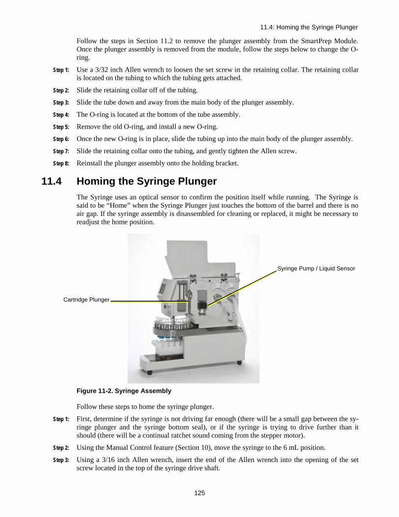
11.4: Homing the Syringe Plunger
125
Follow the steps in Section 11.2 to remove the plunger assembly from the SmartPrep Module. Once the plunger assembly is removed from the module, follow the steps below to change the O-ring.
Step 1: Use a 3/32 inch Allen wrench to loosen the set screw in the retaining collar. The retaining collar is located on the tubing to which the tubing gets attached.
Step 2: Slide the retaining collar off of the tubing.
Step 3: Slide the tube down and away from the main body of the plunger assembly.
Step 4: The O-ring is located at the bottom of the tube assembly.
Step 5: Remove the old O-ring, and install a new O-ring.
Step 6: Once the new O-ring is in place, slide the tubing up into the main body of the plunger assembly.
Step 7: Slide the retaining collar onto the tubing, and gently tighten the Allen screw.
Step 8: Reinstall the plunger assembly onto the holding bracket.
11.4 Homing the Syringe Plunger The Syringe uses an optical sensor to confirm the position itself while running. The Syringe is said to be “Home” when the Syringe Plunger just touches the bottom of the barrel and there is no air gap. If the syringe assembly is disassembled for cleaning or replaced, it might be necessary to readjust the home position.
Figure 11-2. Syringe Assembly
Follow these steps to home the syringe plunger.
Step 1: First, determine if the syringe is not driving far enough (there will be a small gap between the sy-ringe plunger and the syringe bottom seal), or if the syringe is trying to drive further than it should (there will be a continual ratchet sound coming from the stepper motor).
Step 2: Using the Manual Control feature (Section 10), move the syringe to the 6 mL position.
Step 3: Using a 3/16 inch Allen wrench, insert the end of the Allen wrench into the opening of the set screw located in the top of the syringe drive shaft.
Cartridge Plunger
Syringe Pump / Liquid Sensor

11: Routine Operations
126
Step 1: If the syringe plunger needs to be lowered to remove an air gap, rotate the Allen wrench counter-clockwise a fraction of a turn.
Step 2: If the syringe plunger is driving too far and makes a ratchet sound, rotate the Allen wrench clockwise.
Step 4: Remove the Allen wrench.
Step 5: Use the Manual Control function: Syringe Home to test the position of the Syringe within the Sy-ringe Assembly.
Step 6: Visually inspect the space between the syringe plunger seal and the bottom seal. If there is still a gap, rotate the set screw a fraction of a turn counterclockwise. Repeat this sequence until the air gap is minimized or any ratcheting sound has stopped.
11.5 Adjusting the Carousel Offset Position Follow these steps to adjust the rotation positioning of the carousel. This operation should be per-formed if the plunger is not smoothly entering into the opening of the SPE cartridge body or if the plunger fails to enter into the opening of the SPE cartridge body and stops the module with an error message: Cartridge Alignment.
Step 1: If the cartridge plunger is pressed down on top edge of a cartridge body and the module Touch Screen displays the message Cartridge Alignment, press the Abort button on the screen.
Step 2: At the PC, click the Advanced Options button.
Step 3: Click the Set Up Module button.
Step 4: Click Calibration in the menu bar.
Step 5: At the bottom of the window, click the Plunger Up button until the plunger is completely in the up position.
Step 6: In the center of the window, click the Home Shuttle button. The shuttle will move and “home.”
Step 7: When the shuttle is “homed,” click the Offset button. This will move the carousel to position #21.
Step 8: At the bottom of the window, reduce the move Plunger timer to 0.2 seconds. Use the left arrow button.
Step 9: Click the Plunger Dn button one time. This will move the Plunger down until it is over the car-tridge opening. Visually inspect the alignment of the plunger to the cartridge opening.
Step 10: If the carousel needs to be moved clockwise, increase the Carousel Home Offset value by 20 or 30. If the carousel needs to be moved counterclockwise, decrease the Carousel Home Offset value by 20 or 30. Click the Offset button. The carousel will first home and return to position #21.
Step 11: Visually observe that the opening of the cartridge body is positioned under the tip of the plunger.
Step 12: Visually inspect the alignment and, if necessary, repeat Step 10, until the cartridge body opening is positioned directly beneath the plunger.
Step 13: Click Save and Exit on the Calibration screen to save the new offset value.
11.6 Adjusting the Syringe Liquid Sensor Position The Syringe Liquid Sensor is a very useful feature and can be used for two purposes. The first use can be to confirm that reagent has been pulled into the syringe, so the proper chemistry will occur. If the Liquid Sensor detects that no reagent is present, an Alert icon will be displayed on the PC screen, and the message “Liquid Test Failed” will be displayed on the Touch Screen dis-

11.6: Adjusting the Syringe Liquid Sensor Position
127
play. The module will pause and wait for corrective action from the operator. Once the problem has been fixed, the module can be resumed or aborted. The operations that allow the use of the Liquid Sensor are Condition, Wash, Sample Bottle Rinse, Elute, Add to Mixing Chamber, Prime Reagent Lines, Clean Sample Lines, and Clean Plunger. If this is the primary use for the Liquid Sensor, then the sensor housing should be set to around 1.0 mL. This position is indicated by the etch marks on the guide rails that the sensor housing travels on.
The second use of the Liquid Sensor is to estimate the actual volume of the sample processed. This eliminates the need to mark the sample bottle, refill the bottle to the mark with tap water, and pour the water into a graduated cylinder and record the volume. As the maximum syringe volume is 6 mL, it is best to set the Liquid Sensor at the 3 mL mark. Follow the steps below to adjust the position of the Liquid Sensor.
Step 1: Use a 5/64 inch Allen wrench to loosen the two set screws in the front plate of the Liquid Sensor housing. A double pair of wires behind the housing runs through the chassis, so move the housing slowly and gently.
Step 2: On the PC, select the module icon for the Liquid Sensor that is to be adjusted.
Step 3: Click the Advanced Options button.
Step 4: Open the Manual Control window.
Step 5: Click the down arrow and select Syringe Pos.
Step 6: In the new entry box that appears, enter 1.1 if the reagents are to be monitored or 3.1 if the esti-mated volume is to be calculated.
Step 7: Click the Run Step button. The syringe will move to the proper volume.
Step 8: Gently slide the Liquid Sensor housing up until the etching in the sensor housing is even with the bottom of the Syringe Plunger. For convenience, tighten one of the set screws to hold the hous-ing in place.
Step 9: In the Manual Control window, click the down arrow and select Liquid Check.
Step 10: Click the Run Step button.
Step 11: If the housing is too high and the optical beam is blocked by the bottom of the syringe plunger seal, the message Liquid = True will be displayed in the right side box. Loosen the set screw and lower the housing. Repeat this until the message Liquid = False is seen. Note: for the Liquid Check command within Manual Control to work, it must first be initialized by running a method.
Step 12: Tighten both set screws. The Liquid Sensor is now set to the proper position.
Notes:

128
Service 12
12.1 Taking a Module Off-Line If a module needs to be removed or taken off-line for any reason, follow these steps.
Step 1: Turn off the power using the front power switch.
Step 2: On the Reagent Valve (V1), remove all liquid lines from the reagent bottles and ensure there is no liquid left within the instrument.
Step 3: On the Sample Valve (V2), remove all liquid lines from any sample bottles and ensure there is no liquid left within the instrument.
Step 4: On the back side of the module, remove the power cable and the USB cable.
Step 5: On the nitrogen pressure bracket assembly, set the regulators to 0. On the back side of the module, slowly remove the nitrogen gas fittings. If the nitrogen gas lines are connected to multiple modules, cap the open lines just disconnected.
Step 6: Disconnect the Waste Block Drain Lines from the waste container.
The module is now ready to be moved to a new location.
If other modules are still being run from the computer, the overall communications speed will be faster if the Comm port is configured to remove the assigned Comm port for the removed module. See section 5.5.1 for the Comm port instructions and enter a 0 for the Comm port previously assigned to the removed module.
Troubleshooting
Symptom Probable Cause Solution
Error Code 1 Liquid Test Failed, no liquid is
sensed and Liquid Sense is turned on
Fill sample bottle
Error Code 2 Cartridge Alignment Error, plunger is not entering car-
tridge smoothly
See Plunger not centered on cartridge error described below
Error Code 3 SPE Column Missing, no car-tridge in a carousel position used in the method set up
Place cartridge in carousel position
Error Code 4 SPE Column Blocked, may be
clogged with sample If sample has too much particulate, split sample and use multiple cartridges
Vent drips Worn valve seal Replace seal and rotor
Syringe sip or dispense speeds are too high. Reduce the sip or dispense speeds
Calibration missing Improper shutdown Re-enter calibration – save and exit
Syringe does not dis-pense all of the fluid within it
Syringe home position is not set correctly Loosen setscrew at top of the syringe

12.1: Taking a Module Off-Line
129
Syringe bounces (ratch-eting noise) at bottom of stroke
Syringe home position is not set correctly Tighten setscrew at top of the syringe
Plunger squeals Worn o-ring Replace o-ring
Alignment Adjust the Carousel Offset position to properly align the Plunger with the Carou-sel
Pre-load too high Loosen setscrew at top of plunger to adjust pre-load
Fluids above plunger o-ring Worn o-ring Replace o-ring
Preload too low Loosen setscrew at top of plunger and ad-just pre-load
Waste line blockage Inspect fluid path for blockage. Ensure that the Waste Container has a vent port so that the pressure does not build up
Plunger not centered on cartridge
Carousel Offset Incorrect
Adjust the Carousel Offset position to properly align the Plunger with the Carou-sel
No Cartridge Insert is being used
For 1 or 3-mL cartridges, a cartridge insert must be used
Fluid above syringe head Worn syringe head Replace syringe assembly
Waste line blockage Is fluid being expelled though waste line? Inspect fluid path for blockage.
When using the Liquid Sense option, the Sy-ringe does not stop pumping
Liquid level sensor set incor-rectly
Adjust liquid level sensor
Fluid on top of waste block
Waste bottles placed above machine
Place bottles below waste line elevation
Waste block/line blockage Repair/replace waste block
Waste Block Calibration Incorrect
Calibrate the Waste Block positions
Air bubbles in tubing Kinked tubing Trim or replace
Loose fitting Tighten – Teflon® fittings finger tight only
Worn valve seal Replace valve seal and rotor
For all other service related issues, please contact Horizon Technology, Inc. at 603-893-3663 and ask for Customer Service.

12: Service
130
Notes:

131
Part IV: Appendices

A: Technical Description
132
A Technical Description
Equipment Specifications Specification Description
Weight 43 lb (19.50 kg) Dimensions Height: 18 in (45.7 cm)
Width: 8.5 in (21.6 cm) Depth: 22.5 in (57.2 cm)
Power Module 24 VDC, 1.0 amp (from power supply) Power Supply Line Voltage 100-240 VAC (to power supply)
Line Frequency 50-60 Hz Maximum Power 100 Watts Uses an IEC type connector to accept various international power cords
Accessories and Kits Refer to the Horizon Technology online catalog (http://www.horizontechstore.com/ ) for spare parts, accessories, and consumables.
For a complete listing and current pricing, contact the Horizon Technology Orders Department:
603-893-3663
Measurements are in inches and [mm]

12.1: Taking a Module Off-Line
133
Notes:
Measurements are in inches and [mm]
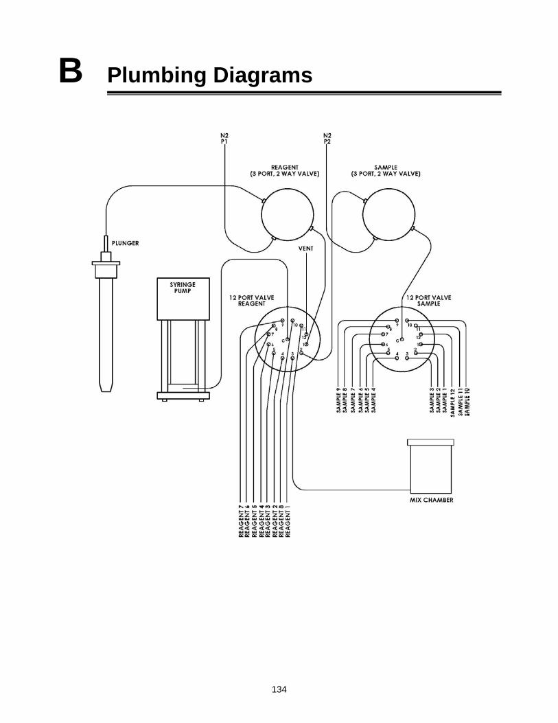
134
B Plumbing Diagrams

12.1: Taking a Module Off-Line
135
Notes:
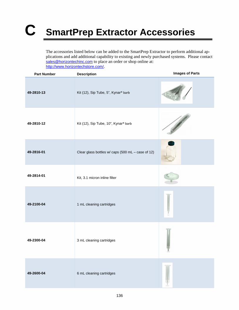
136
C SmartPrep Extractor Accessories
The accessories listed below can be added to the SmartPrep Extractor to perform additional ap-plications and add additional capability to existing and newly purchased systems. Please contact [email protected] to place an order or shop online at: http://www.horizontechstore.com/.
Part Number Description Images of Parts
49-2810-13 Kit (12), Sip Tube, 5”, Kynar® barb
49-2810-12 Kit (12), Sip Tube, 10”, Kynar® barb
49-2816-01 Clear glass bottles w/ caps (500 mL – case of 12)
49-2814-01 Kit, 3.1 micron inline filter
49-2100-04 1 mL cleaning cartridges
49-2300-04 3 mL cleaning cartridges
49-2600-04 6 mL cleaning cartridges

12.1: Taking a Module Off-Line
137
49-2600-01 6 mL SmartPrep Plunger Assembly (order with PN 49-2600-02)
49-2300-01 3 mL SmartPrep Plunger Assembly (order with PN 49-2300-02)
49-2100-01 1 mL SmartPrep Plunger Assembly (order with PN 49-2100-02)
49-2100-11 (1 mL)
49-2600-11 (6 and 3 mL)
Immunoaffinity cartridge plunger and stripper block 1 mL or 6 and 3 mL
49-2600-02 6 mL Cartridge Stripper Block (order with PN 49-2600-01)
49-2300-02 3 mL Cartridge Stripper Block (order with PN 49-2300-01)
49-2100-02 1 mL Cartridge Stripper Block (order with PN 49-2100-01)
49-2300-03 3 mL Cartridge Carousel Insert Adapters
49-2100-03 1 mL Cartridge Carousel Insert Adapters

C: SmartPrep Extractor Accessories
138
49-2815-01 SmartPrep Sample Bottle Rack
49-2810-01 SmartPrep 6 Bottle Rinse Tubing Enclosure (order with PN 49-2810-04)
49-2810-04 Nozzle Kit for Bottle Rinse (order with PN 49-2810-01)
49-2812-01 Collection Rack, 2x6 20 mL VOA vials
49-2812-02 Collection Rack, 2x6 40 mL VOA vials
49-2812-03 Collection Rack, 2x6 13x100 mm test tubes
49-2812-06 Collection Rack, 2x6 for twelve conical bottom centrifuge tubes with ground glass top 15 mm x 100 mm

12.1: Taking a Module Off-Line
139
49-2812-07 Collection Rack, 2X6 for twelve “Elka, AR®/soda glass, round bottom, with rim, 15.5 x 100 mm col-lection tubes
49-2812-09 Collection Rack, 2x6 for twelve 20-mL crimp-top rounded bottom headspace vial 22 x 75 mm, 20 mm collar
49-2812-10 Collection Rack, 2x6 for twelve custom conical bottom graduated test tube 17 x 100 mm
49-2812-11 Collection Rack, 2x6 for twelve standard 16 x 100 mm test tubes
160-0008-02 Collection vials, 20 mL VOA vials (case of 72)
160-0008 Collection vials, 40 mL VOA vials (case of 72)
49-2817-02 Kit, Septa, 22mm x 25 mm, 100 PK

C: SmartPrep Extractor Accessories
140
49-2817-01 Collection Vial Caps, Open Top for 20 mL and 40 mL VOA Vials (12 PK)
03-0100-01 50-mL conical bottom, graduated glass tube, case (12)
03-0300-01 Collection vials 13x100 mm tubes, case
49-2818-03 20 liter plastic carboy for waste collection, special top
99-2810 Containment tray
04-2003 Rack only – for 50 mL conical tubes Note: for use with PN 03-0100-01
04-2001 50 mL conical tubes + rack/tray

12.1: Taking a Module Off-Line
141
04-2002 15 mL conical tubes + rack/tray

D: Editing a V1.0.0.18 Method to run in V2.0
142
D Editing a V1.0.0.18 Method to run in V2.0
Methods generated in V2.0 should be opened and in-spected in Version 3. If they look as ou expect save them and they are ready to go. Methods generated in V1.0.0.18 are available to edit and run in V2.0 with additional effort. Editing a method is necessary due to the changes to the load operation options and names. The steps described below will assist you in editing and saving your method from within V2.0:
1. Locate the V1.0.0.18 SmartPrep Method Converter.xlt file from the C:\HorizonTechnologySP\SmartPrep\Factory Methods folder. This file is installed only with the V2.0 SmartPrep Extractor software.
2. Open the V1.0.0.18 SmartPrep Method Converter.xlt file. Click on the TEMPLATE worksheet.
3. Locate the SmartPrep Extractor Method to edit from this location on your computer: C:\HorizonTechnologySP\SmartPrep\Methods. Methods are indicated by a .PRO extension. Right click on the method file to edit, and select Open With. Choose to open with Excel.
4. When the method file opens in Excel, click on the column A header to select the entire contents of column A. Right click and select Copy.
5. Click back to the TEMPLATE worksheet within the V1.0.0.18 SmartPrep Method Converter.xlt,
and right click on cell A1 to Paste the previously copied contents.
6. Your method file will appear in a series of steps listed in column G. The parameters for each step are listed across the Excel worksheet as individual columns. Look for the step called Load Sample (as indicated by the red arrow in the example below).

12.1: Taking a Module Off-Line
143
7. The information displayed for the Load Sample step is what will be used to edit the method using the new operation called Load Large Volume Sample.
8. Open the method to be edited within the SmartPrep Extractor Software V2.0.
9. Click on the operation line within the Method Description box. Click the Insert button to create a new blank line above the Load operation.
PAUSE PURGE PURGERATE 1 RATE 2 LIQUID PAUSE TIME TIME TIMESip or Sip or SENSE MIXING MIN. EXPECTED TIME UNITS [DRY] UNITS
SOURCE VOLUME Delivery Delivery True (ON) CYCLES VOLUME VOLUME e.g. Soak (appears N2 Purge (appearsSTEP OPERATION Reagent, Vent, or Sample DESTINATION (mL) (mL/min) (mL/min) False (OFF) # (mL) (mL) CHOICE (sec) unused) (sec) unused) MESSAGE
METHOD NAME 1 2 3 4 5 6 7 8 9 10 11 12 13 14 15 16521 1 Condition cartridge Methylene Chloride 0 3 10 0 TRUE 0 0 0 0 10 0 5 0 0
CARTRIDGE MEDIA 2 Condition cartridge Methylene Chloride 0 3 10 0 TRUE 0 0 0 0 10 0 5 0 0Coconut Charcoal 3 Condition cartridge Methanol 0 3 10 0 TRUE 0 0 0 0 10 0 5 0 0CARTRIDGE SIZE 4 Condition cartridge Methanol 0 3 10 0 TRUE 0 0 0 0 10 0 5 0 0
6 5 Condition cartridge Methanol 0 3 10 0 TRUE 0 0 0 0 10 0 0 0 0NO. OF STEPS IN METHOD 6 Condition cartridge Methanol 0 3 10 0 TRUE 0 0 0 0 10 0 0 0 0
17 7 Condition cartridge Reagent Water 0 3 10 0 TRUE 0 0 0 0 0 0 0 0 0Spare Field 1 8 Condition cartridge Reagent Water 0 3 10 0 TRUE 0 0 0 0 0 0 0 0 0
0 9 Condition cartridge Reagent Water 0 3 10 0 TRUE 0 0 0 0 0 0 0 0 0Spare Field 2 10 Condition cartridge Reagent Water 0 3 10 0 TRUE 0 0 0 0 0 0 0 0 0
0 11 Condition cartridge Reagent Water 0 3 10 0 TRUE 0 0 0 0 0 0 0 0 012 Condition cartridge Reagent Water 0 3 10 0 TRUE 0 0 0 0 0 0 0 0 013 Load sample Sample bottle Water Sample Waste 0 75 10 FALSE 0 300 500 0 0 0 0 0 014 N2 purge timer step 0 0 0 0 0 FALSE 0 0 0 0 0 0 10 0 015 Elute cartridge Methylene Chloride 1st Collection Tube 3 5 0 TRUE 0 0 0 0 60 0 0 0 016 Elute cartridge Methylene Chloride 1st Collection Tube 5 5 0 TRUE 0 0 0 0 0 0 0 0 017 Elute cartridge Methylene Chloride 1st Collection Tube 5 5 0 TRUE 0 0 0 0 10 0 10 0 018 0 0 0 0 0 0 0 0 0 0 0 0 0 0 0 019 0 0 0 0 0 0 0 0 0 0 0 0 0 0 0 020 0 0 0 0 0 0 0 0 0 0 0 0 0 0 0 021 0 0 0 0 0 0 0 0 0 0 0 0 0 0 0 022 0 0 0 0 0 0 0 0 0 0 0 0 0 0 0 023 0 0 0 0 0 0 0 0 0 0 0 0 0 0 0 024 0 0 0 0 0 0 0 0 0 0 0 0 0 0 0 025 0 0 0 0 0 0 0 0 0 0 0 0 0 0 0 0

D: Editing a V1.0.0.18 Method to run in V2.0
144
10. Double click to select the Load Large Volume Sample operation. Enter the parameters from the .xlt step for Load Sample into the Load Large Volume Sample operation screen. Click OK.
11. The new Load operation will be added to the Method Description box as the first Load operation in the list. Click on the second Load operation in the list, and click the Delete button.
12. Save the newly edited method with a new name, using the version within the name to differentiate from the previous V1.0.0.18 method.

12.1: Taking a Module Off-Line
145

E: Factory Supplied Green Food Coloring Methods
146
E Factory Supplied Green Food Color-ing Methods
Guidelines:
• The following factory methods are available to use as examples with McCormick green food coloring as the sample. This can be found either at your local grocery or food store or online at : http://www.mccormick.com. The factory methods will also operate with a manual mixture of FD&C Yellow 5 and FD&C Blue 1 from the McCormick 4-color assorted pack. Both sets of sample preparation instructions and results are included. It is important to read through these guidelines prior to running these methods.
• Within the C:\HorizonTechnologySP\SmartPrep\Factory Methods\Green Food Color Methods folder, these methods will be available to copy.
McCormick Green
Manual Mixture
McCormick Green
Manual Mixture
McCormick Green
Manual Mixture
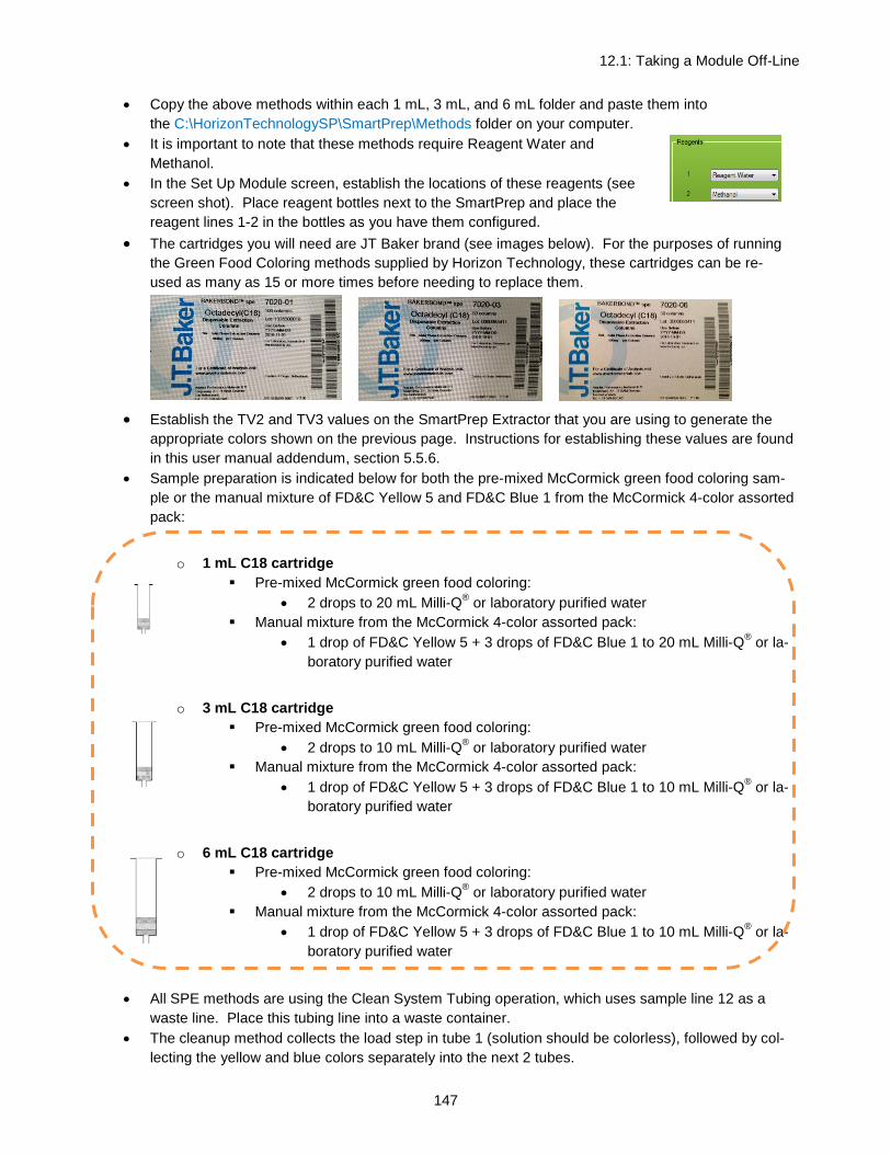
12.1: Taking a Module Off-Line
147
• Copy the above methods within each 1 mL, 3 mL, and 6 mL folder and paste them into the C:\HorizonTechnologySP\SmartPrep\Methods folder on your computer.
• It is important to note that these methods require Reagent Water and Methanol.
• In the Set Up Module screen, establish the locations of these reagents (see screen shot). Place reagent bottles next to the SmartPrep and place the reagent lines 1-2 in the bottles as you have them configured.
• The cartridges you will need are JT Baker brand (see images below). For the purposes of running the Green Food Coloring methods supplied by Horizon Technology, these cartridges can be re-used as many as 15 or more times before needing to replace them.
• Establish the TV2 and TV3 values on the SmartPrep Extractor that you are using to generate the appropriate colors shown on the previous page. Instructions for establishing these values are found in this user manual addendum, section 5.5.6.
• Sample preparation is indicated below for both the pre-mixed McCormick green food coloring sam-ple or the manual mixture of FD&C Yellow 5 and FD&C Blue 1 from the McCormick 4-color assorted pack:
o 1 mL C18 cartridge
Pre-mixed McCormick green food coloring: • 2 drops to 20 mL Milli-Q® or laboratory purified water
Manual mixture from the McCormick 4-color assorted pack: • 1 drop of FD&C Yellow 5 + 3 drops of FD&C Blue 1 to 20 mL Milli-Q® or la-
boratory purified water
o 3 mL C18 cartridge Pre-mixed McCormick green food coloring:
• 2 drops to 10 mL Milli-Q® or laboratory purified water Manual mixture from the McCormick 4-color assorted pack:
• 1 drop of FD&C Yellow 5 + 3 drops of FD&C Blue 1 to 10 mL Milli-Q® or la-boratory purified water
o 6 mL C18 cartridge
Pre-mixed McCormick green food coloring: • 2 drops to 10 mL Milli-Q® or laboratory purified water
Manual mixture from the McCormick 4-color assorted pack: • 1 drop of FD&C Yellow 5 + 3 drops of FD&C Blue 1 to 10 mL Milli-Q® or la-
boratory purified water
• All SPE methods are using the Clean System Tubing operation, which uses sample line 12 as a waste line. Place this tubing line into a waste container.
• The cleanup method collects the load step in tube 1 (solution should be colorless), followed by col-lecting the yellow and blue colors separately into the next 2 tubes.

E: Factory Supplied Green Food Coloring Methods
148
o Yellow – elutes with Reagent Water o Blue – elutes with 100% MeOH
• The load method only collects the yellow and blue colors into tubes 2 and 3. Tube 1 is empty. o Yellow – elutes with Reagent Water o Blue – elutes with 100% MeOH
• Additional notes: o Each SPE method includes a “Pause with Message” operation at the beginning prior to
running the sample. o Run the Prime method to properly prepare the solvent lines prior to running one or more
Cleanup or Load methods.
Pre Run: Primes all solvent lines
1: Cleanup Method (collects load step)
2: Load Method (does not collect load step)
12.1: Taking a Module Off-Line
149
F Limited Warranty
Horizon Technology, Inc. warrantees the SmartPrep Module (Product) against defects in mate-rial or workmanship as follows:
1. LABOR: For a period of one year from the date of purchase, if this Product is determined to be defective, Horizon will repair the Product, and will cover all labor charges. The Product must be returned to Horizon Technology, prepaid, for repair. Horizon will pay the return shipping charges.
2. PARTS: Horizon will supply, at no charge, new replacement parts for a period of one (1) year. Horizon will send the replacement parts directly to the customer site, for customer in-stallation. If the customer does not wish to install these parts, the Product must be returned to Horizon Technology for the necessary repairs. The customer is responsible for shipment of the Product to Horizon.
To obtain warranty service, the Product must be delivered prepaid, in the original packaging. If needed, new packaging is available from Horizon Technology.
Warnings and Restrictions of use of the SmartPrep Module System The following Warnings and Restrictions of use are to guide the operator for safe and effective use of the Horizon Technology SmartPrep extractor. Failure to use the SmartPrep as intended will void the warranty.
Warnings and Restrictions The SmartPrep Module is intended for use only with clean, particulate free water samples.
Cloudy or particulate-laden samples can damage close tolerance components and clog flow paths (leading to instrument damage). In-line filters are available and recommended for added protec-tion of the instrument from questionable samples.
• The SmartPrep Module is not intended for use with hydrofluoric acid.
• The SmartPrep Module is not intended for use with radioactive materials.
• The SmartPrep Module will not be accepted for service or repair or preventative mainte-nance if exposed to radioactive or biological contamination.
• The SmartPrep Module should not be left for extended periods of time with reagents throughout the tubing and other fluidic components, but rather, routinely flushed of rea-gents (methanol flushed) and tubing paths blown dry using clean nitrogen gas.
• The SmartPrep Module should not be stored with reagents or samples within the fluid path.
• The SmartPrep Module requires routine maintenance and replacement of wear items, in-cluding Plunger Seals, Waste Block Seals, Syringe Pump wetted components, and 12 Port Valve (Seal and Rotor).
• The SmartPrep Module should not be cleaned with any reagents hasher than iso-propanol.
• The SmartPrep Module although resistant to typical reagents and minor seal leakage, is not intended to be resistant to spills into, or on the unit.

F: Limited Warranty
150
This warranty does not cover customer installation, or set up adjustments and/or Product optimi-zation. The warranty also does not cover cosmetic damage or damage due to acts of nature, acci-dent, misuse, abuse, negligence, or modifications of, or to any part of the Product. This warranty does not cover damage due to improper operation or maintenance, or attempted repair of any electrical components.
No other warranties are expressed or implied.
For service assistance or resolution of a service problem, or for product information or operation, contact:
Horizon Technology, Inc.
(800)-997-2997 (Toll-free, US Only)
+1-(603)-893-3663
Horizon Technology, Inc.
16 Northwestern Drive Salem, NH 03079
Email: [email protected]
Website: www.horizontechinc.com