
Smartgridand Renewable
10
Smart Grid and Renewable Energy Systems Frede Blaabjerg 1 and Josep M. Guerrero 1,2 1 Aalborg University, Institute of Energy Technology Pontoppidanstraede 101, DK-9220 Aalborg East, Denmark 2 Technical University of Catalonia, Urgell 187, 08036 – Barcelona, Spain [email protected] , [email protected] Abstract – The electrical energy consumption continues growing and more applications relay on electricity. We can expect that more 60 % of all energy consumption will be converted and used as electricity. Therefore, it is a demand that production, distribution and use of electrical energy are done as efficient as possible. Further, the recent challenges with nuclear power plants are arguing to find more sustainable energy generation solutions. Of many options, two major technologies will play important roles to solve parts of those future challenges. One is to change the electrical power production from conventional, fossil based energy sources to renewable energy sources. Another is to use high efficient power electronics in power generation, power transmission/distribution and end-user application. This paper discus trends of the future grid infrastructure as well as the most emerging renewable energy sources, wind energy and photovoltaics. Then main focus is on the power electronics and control technology for wind turbines as they are the largest renewable power contributor, allowing their penetration into a SmartGrid to be even higher in the future. I. I NTRODUCTION Distributed power Generation (DG) is emerging as a new paradigm to produce on-site highly reliable and good quality electrical power. Thus, DG systems are presented as a suitable form to offer highly reliable electrical power supply. The concept is particularly interesting when different kinds of energy resources are available, such as photovoltaic (PV) panels, fuel cells (FCs), or wind turbines. The DG of different kinds of energy systems allows for the integration of renewable and nonconventional energy resources [1]. Hence, the DG is becoming a part of strategic plans for most countries to address current challenges associated with energy management [2]. Today, electrical and energy engineering have to face a new scenario in which small distributed power generators and dispersed energy storage devices have to be integrated together into the grid. The new electrical grid will deliver electricity from suppliers to consumers using communication technology to control appliances at consumer’s homes to save energy, reducing cost and increasing reliability and transparency. The idea beh ind this concept is to have devices that plug into your outlet and you would plug your appliance into this device. These devices would communicate and report to the electric companies at what time your appliance used energy and how much energy was used. This will in turn charge you more for the electricity that you use during peak hours of late afternoon and early evening. In this sense, the expected whole energy system will be more interactive, intelligent, and distributed. Thus wide-spread use of renewable energy sources in distribution networks is seen [1], [2]. For instance, Denmark has a high power capacity penetration ( > 30 %) of wind energy i n major areas of the country and today 28 % of the whole electrical energy consumption is covered this kind of energy. The main advantages of using renewable energy sources are the elimination of harmful emissions and the inexhaustible resources of the primary energy. However, the main disadvantage, apart from the higher costs is the uncontrollability as they are completely weather-based. The availability of renewable energy sources has strong daily and seasonal patterns and the power demand by the consumers could have a very different characteristic. Therefore, it is difficult to operate a power system installed with only renewable generation units due to the characteristic differences and the high uncertainty in the availability of the renewable energy sources without any load control. This is further strengthened as no real large scale electrical energy storage systems exist. The wind turbine technology is one of the most emerging renewable energy technologies [3]-[12]. It started in the 1980’es with a few tens of kW production power per unit to today with multi-MW size wind turbines that are being installed. It also means that wind power production in the beginning did not have any impact on the power system control but now due to their size they have to play an active part in the grid operation. The technology used in wind turbines was in the beginning based on a squirrel-cage induction generator connected directly to the grid. By that power pulsations in the wind are almost directly transferred to the electrical grid. Furthermore, there was no control of the active and reactive power except from some capacitor banks, which are important control devices to regulate the frequency and the voltage in the grid system. As the power range of the turbines increases those control parameters become very important and power electronics [5] is introduced as an interface between the wind turbine and the grid. The power
-
Upload
sai-pranahita-bhaskarapantulu -
Category
Documents
-
view
215 -
download
0
Transcript of Smartgridand Renewable

8/13/2019 Smartgridand Renewable
http://slidepdf.com/reader/full/smartgridand-renewable 1/10
Smart Grid and Renewable Energy Systems
Frede Blaabjerg1 and Josep M. Guerrero1,2 1
Aalborg University, Institute of Energy Technology
Pontoppidanstraede 101, DK-9220 Aalborg East, Denmark2 Technical University of Catalonia, Urgell 187, 08036 – Barcelona, Spain
[email protected] , [email protected]
Abstract – The electrical energy consumption continues
growing and more applications relay on electricity. We
can expect that more 60 % of all energy consumption will
be converted and used as electricity. Therefore, it is a
demand that production, distribution and use of electrical
energy are done as efficient as possible. Further, the
recent challenges with nuclear power plants are arguing tofind more sustainable energy generation solutions. Of
many options, two major technologies will play important
roles to solve parts of those future challenges. One is to
change the electrical power production from conventional,
fossil based energy sources to renewable energy sources.
Another is to use high efficient power electronics in power
generation, power transmission/distribution and end-user
application. This paper discus trends of the future grid
infrastructure as well as the most emerging renewable
energy sources, wind energy and photovoltaics. Then main
focus is on the power electronics and control technology
for wind turbines as they are the largest renewable power
contributor, allowing their penetration into a SmartGrid
to be even higher in the future.
I. I NTRODUCTION
Distributed power Generation (DG) is emerging as a
new paradigm to produce on-site highly reliable and
good quality electrical power. Thus, DG systems are
presented as a suitable form to offer highly reliable
electrical power supply. The concept is particularly
interesting when different kinds of energy resources are
available, such as photovoltaic (PV) panels, fuel cells
(FCs), or wind turbines. The DG of different kinds of
energy systems allows for the integration of renewable
and nonconventional energy resources [1].Hence, the DG is becoming a part of strategic plans
for most countries to address current challenges
associated with energy management [2]. Today,
electrical and energy engineering have to face a new
scenario in which small distributed power generators
and dispersed energy storage devices have to be
integrated together into the grid. The new electrical gridwill deliver electricity from suppliers to consumers
using communication technology to control appliances
at consumer’s homes to save energy, reducing cost and
increasing reliability and transparency. The idea behind
this concept is to have devices that plug into your outlet
and you would plug your appliance into this device.These devices would communicate and report to the
electric companies at what time your appliance used
energy and how much energy was used. This will inturn charge you more for the electricity that you use
during peak hours of late afternoon and early evening.
In this sense, the expected whole energy system will be
more interactive, intelligent, and distributed. Thus
wide-spread use of renewable energy sources in
distribution networks is seen [1], [2].
For instance, Denmark has a high power capacity
penetration (> 30 %) of wind energy in major areas ofthe country and today 28 % of the whole electrical
energy consumption is covered this kind of energy. The
main advantages of using renewable energy sources are
the elimination of harmful emissions and the
inexhaustible resources of the primary energy.
However, the main disadvantage, apart from the highercosts is the uncontrollability as they are completely
weather-based. The availability of renewable energy
sources has strong daily and seasonal patterns and the power demand by the consumers could have a very
different characteristic. Therefore, it is difficult tooperate a power system installed with only renewable
generation units due to the characteristic differences
and the high uncertainty in the availability of the
renewable energy sources without any load control.
This is further strengthened as no real large scale
electrical energy storage systems exist.
The wind turbine technology is one of the most
emerging renewable energy technologies [3]-[12]. It
started in the 1980’es with a few tens of kW production
power per unit to today with multi-MW size wind
turbines that are being installed. It also means that wind power production in the beginning did not have anyimpact on the power system control but now due to
their size they have to play an active part in the grid
operation. The technology used in wind turbines was in
the beginning based on a squirrel-cage induction
generator connected directly to the grid. By that power
pulsations in the wind are almost directly transferred tothe electrical grid. Furthermore, there was no control of
the active and reactive power except from some
capacitor banks, which are important control devices to
regulate the frequency and the voltage in the grid
system. As the power range of the turbines increases
those control parameters become very important and power electronics [5] is introduced as an interface
between the wind turbine and the grid. The power
8/13/2019 Smartgridand Renewable
http://slidepdf.com/reader/full/smartgridand-renewable 2/10
electronics is able to change the b
the wind turbine from being an ene
active power source. The electrical
wind turbine is not new. It has
several years but now the price pr.
low, that solutions with power eattractive [3]-[35].
The development of PV has als
Every year the price pr. produced k
improving the solar cells themselve
the PV-inverters more efficient and
The PV-technology is workingtechnology lines – all are needing
move from basic research to use i
scale products. Power electronics
enable the PV technology to be co
system [47]-[63].
Both technologies are changingmore uncontrolled and heterogene
operators are developing new met
grid – e.g. in a smart-grid structureto communication, control, safety,
are becoming defined [2].The scope of this paper is to gi
discuss some trends in wind
technologies as well as to put it
context where both power prod
consumption is controlled. First, an
system is shown where the societDG based infrastructure based on
smaller combined heat and powe
future grid infrastructure is propo
Next, the basic market developmen
PV and wind turbines which for tmost emerging technologies. Nturbine configurations are expl
comparison. Different control m
explained for state-of-the art wind
the grid codes which are pushing th
as it is makes a smart grid infr
Different technologies to improve t
the power systems are also neces
Finally, a discussion about the futur
II. THE DANISH ELECTRICAL PO
PARADIGM FOR DISTRIBUTED
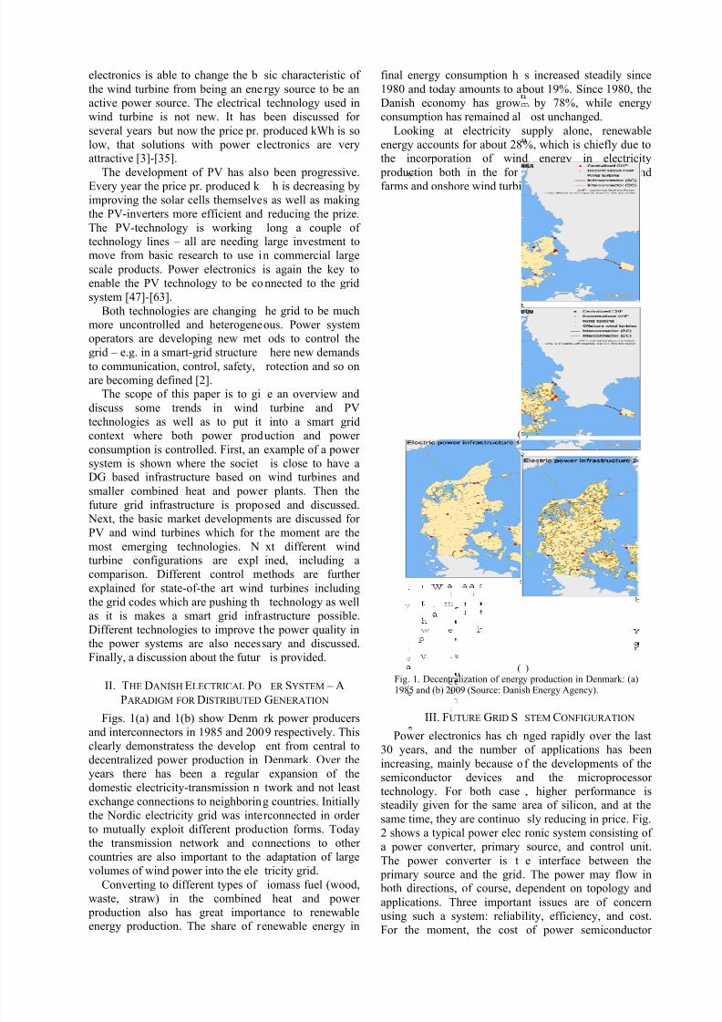
Figs. 1(a) and 1(b) show Denmand interconnectors in 1985 and 200
clearly demonstratess the develop
decentralized power production in
years there has been a regular
domestic electricity-transmission n
exchange connections to neighborin
the Nordic electricity grid was inte
to mutually exploit different produ
the transmission network and co
countries are also important to the
volumes of wind power into the ele
Converting to different types of
waste, straw) in the combined production also has great importenergy production. The share of r
sic characteristic of
rgy source to be an
technology used in
been discussed for
produced kWh is so
lectronics are very
o been progressive.
h is decreasing by
s as well as making
reducing the prize.
long a couple oflarge investment to
n commercial large
is again the key to
nnected to the grid
he grid to be much
ous. Power system
ods to control the
here new demandsrotection and so on
e an overview and
turbine and PV
into a smart grid
uction and power
example of a power
is close to have awind turbines and
r plants. Then the
sed and discussed.
ts are discussed for
he moment are thext different windined, including a
ethods are further
turbines including
technology as well
astructure possible.
he power quality in
sary and discussed.
is provided.
ER SYSTEM – A
GENERATION
rk power producers9 respectively. This
ent from central to
Denmark. Over the
expansion of the
twork and not least
g countries. Initially
rconnected in order
ction forms. Today
nnections to other
adaptation of large
tricity grid.
iomass fuel (wood,
heat and powerance to renewableenewable energy in
final energy consumption h
1980 and today amounts to a
Danish economy has grow
consumption has remained al
Looking at electricity
energy accounts for about 28the incorporation of win
production both in the for
farms and onshore wind turbi
(
(
Fig. 1. Decentralization of energ1985 and (b) 2009 (Source: Dani
III. FUTURE GRID S
Power electronics has ch
30 years, and the number
increasing, mainly because o
semiconductor devices a
technology. For both casesteadily given for the same
same time, they are continuo
2 shows a typical power elec
a power converter, primary
The power converter is t
primary source and the grid both directions, of course, d
applications. Three importa
using such a system: reliab
For the moment, the cost
s increased steadily since
bout 19%. Since 1980, the
by 78%, while energy
ost unchanged.
supply alone, renewable
%, which is chiefly due tod energy in electricity
of large offshore wind
nes.
)
)
y production in Denmark: (a)sh Energy Agency).
STEM CONFIGURATION
nged rapidly over the last
of applications has been
f the developments of the
nd the microprocessor
, higher performance isarea of silicon, and at the
sly reducing in price. Fig.
ronic system consisting of
source, and control unit.
e interface between the
. The power may flow inependent on topology and
nt issues are of concern
ility, efficiency, and cost.
of power semiconductor

8/13/2019 Smartgridand Renewable
http://slidepdf.com/reader/full/smartgridand-renewable 3/10
devices is decreasing between 1%
for the same output performance,
kilowatt for a power electroni
decreasing. The trend of power elec
shrinking in volume and weight
integration is an important key tomore available functions can be im
product. Accordingly, power electr
point to allow the change fr
centralized grid to a more distribute
depicted in Fig. 3.
In this sense, a Microgrid proposed in [1], based on the hie
Microgrids interconnected b
SmartGrids, is becoming more and
Fig. 4. The proposal is based on
electronics interfaces behave
generators, and regulate every Micr
by means of a three level hierarc
primary control is based on the dr
including an output impedance vsecondary control allows restori
produced by the primary control;control manages the power flow bet
and the external electrical distributi
Fig. 2. Power plants toward distributed
traditional power systems and (b) decensystems.
(a)
(b)
Fig. 3. Power plants toward distributed
traditional power systems and (b) decensystems.
and 5% every year
and the price per
c system is also
tronic conversion is
. This shows that
be competitive, aslemented in such a
onics will be a key
m the traditional
d and smart grid, as
clustering conceptarchical control of
etween forming
more important, see
making the power
like synchronous
ogrid independently
ical control: i) the
op control method,
irtual loop; ii) theng the deviations
and iii) the tertiaryween the Microgrid
n system.
ower generation: (a)
tralized future power
ower generation: (a)
tralized future power
Fig. 4. Multi-Microgrid clusterin
Fig. 5. Annual global cumul
capacity from 1996 to 2010 (sour
Fig. 6. Wind turbine market shar
in 2010 (source: BTM Consult).
IV. NOWADAYS STAT
PHOTO
A. Wind power
The wind power has
worldwide installation level
GW of newly installed win
according to BTM Consult.
that the installed capacity
magnitude to 2300 GW by
published by the Global
Greenpeace International. Th
wind power in 2010 was 1.9market in 2010 with over
general EU, USA and Chin
third each of the total market.
turbine market is shown in Fi
The Danish company Vestin 2010 still on the top p
manufacturers of wind turb
followed by the Chinese c
for SmartGrid [1].
ative installed wind power
ce: GWEC).
distributed by manufacturers
US OF WIND POWER AND
VOLTAICS
grown to a cumulative
f 200 GW with over 39.4
power capacity in 2010,
Now there are predictions
could grow one order of
030, according to a study
ind Energy Council and
e worldwide penetration of
2%. China was the largest
19 GW installed and in
a are sharing around one
The evolution of the wind
g. 5.
as Wind Systems A/S wassition among the largest
ines in the world, closed
ompany Simovel, as the

8/13/2019 Smartgridand Renewable
http://slidepdf.com/reader/full/smartgridand-renewable 4/10
second largest in the world. GE Wind, the Chinese
company Goldwind and German Company Enercon are
in third, fourth and fifth positions, respectively. It is
interesting to notice that three Chinese manufacturers
are in the Top 10 and with a total share of 23.3%. Fig. 6
shows the wind turbine top-suppliers in 2010. Nowadays, the most attractive concept seemed to be
the variable speed wind turbine with pitch control [3]-
[22]. Still some manufacturers are providing the
‘classical’ active stall, fixed speed turbines especially
for countries where the grid codes do not demand
dynamic reactive power control (presently e.g. inChina, parts of USA). However, recently Siemens Wind
Power released a multi-megawatt class variable speed
Full-Scale power Converter (FSC) with a permanent
magnet generator. The most used generator type is
changing from being an induction generator to be with
Permanent Magnet Synchronous Generators (PMSG)where a full scale power conversion is necessary. All
wind turbine manufacturers are using a step-up
transformer for connecting the generator to the grid.Today the DFIG is still dominating the market but in
the future FSC is expected to take over. The transitionis mainly valid for larger wind turbines (3-6 MW).
B. Solar power
PhotoVoltaic (PV) based solar power is like the wind
turbines a booming industry; since 1980, when the
terrestrial applications began. The annual installation of
PV power has increased to above 7 GWp leading tocumulative installed PV power by the end of 2009
reaching to approximately 15 GWp according to EPIA
which actually is 10 % of the wind power capacity. Fig.
7 shows the cumulative PV installed capacity.
The annual growth rate is still very high (>30%)
especially for the last 3 years. As in the previous yearsthe vast majority of new capacity was installed in EU
with Germany as dominating the market followed by
Spain and Italy. USA market is also growing fast
According to Photon Magazine, the prices for PV
modules are decreased by the end of 2009 to around
1.5-2 €/Wp with stronger trends for using thin filmtechnology in order to reach the psychological
threshold of 1 €/Wp, which really will trigger the mass-
penetration of PV as an energy and power source. In
addition to the PV module cost, the cost and reliability
of PV inverters are also important issues. The inverter
cost share represents about 10-15% of the total
investment cost of a grid connected PV system.
Fig. 7. Cumulative PV installed capacity from 2000 to 2009(source: EPIA, http://www.epia.org) [63].
Fig. 8. Development of specific cost and production quantityfor the PV inverter of nominal powers between 1 and 10 kW
during two decades (¦ indicates specific prices of products on
the market) (source: EPIA, http://www.epia.org) [63].
The prices for PV inverters in the 1-10 kW range are
shown in Fig. 8. It can be seen that the inverter cost of
this power class has decreased by more than 50 %
during the last decade. The main reasons for this
reduction are the increase of the production quantitiesand the implementation of new system technologies
(e.g. string-inverters). A further 50 % reduction of the
specific cost is anticipated during the coming decade
which requires the implementation of specific measures
in the development and the manufacturing processes.
V. WIND POWER CONVERSION
Wind turbines capture power from the wind by
means of aerodynamically designed blades and convertit to rotating mechanical power. As the blade tip-speed
should be lower than half the speed of sound the
rotational speed will decrease as the radius of the blade
increases. For multi-MW wind turbines the rotational
speed is 8-13 rpm. So far the most weight efficient way
to convert the low-speed, high-torque power toelectrical power is to use a gear-box and a standard
fixed speed generator as illustrated in Fig. 9.
The gear-box is optional as multi-pole generator
systems are also becoming competitive solutions.
Between the grid and the generator a power converter is
inserted which gives the flexibility to control the powerto the grid and the power from the generator.
There exist many technical solutions for wind
energy/power and convert the mechanical power into
electrical power. The electrical output can either be ac
or dc. In the last case a power converter has to be usedas interface to the grid which also gives maximum
controllability. In the following the two most used
technologies will be discussed and compared with fixed
speed technologies without full scale power converter
(Type A and Type B in Table I).
Fig. 9. Converting wind power to electrical power in a windturbine with the option to use a gearbox and a power converter
[5].

8/13/2019 Smartgridand Renewable
http://slidepdf.com/reader/full/smartgridand-renewable 5/10
Fig. 10. Variable speed wind turbine with partial scale power
converter.
A. Variable Speed WT with partial-scale frequencyconverter (WT Type C)
This configuration is known as the doubly-fed
induction generator (DFIG) concept, which gives a
variable speed controlled wind turbine with a wound
rotor induction generator (WRIG) and partial power-
scale frequency converter (rated to approx. 30% ofnominal generator power) on the rotor circuit. The
topology is shown in Fig. 10.
The stator is directly connected to the grid, while a
partial-scale power converter controls the rotor
frequency and thus the rotor speed. The power rating of
this partial-scale frequency converter defines the speedrange (typically ±30% around synchronous speed).
Moreover, this converter performs the reactive power
compensation and a smooth grid connection. The
control range of the rotor speed is wider compared to
the variable rotor resistance type. The smaller
frequency converter makes this concept attractive from
an economical point of view. In this case the power
electronics is enabling the wind turbine to act as a
dynamic power source to the grid. However, its main
drawbacks are the use of slip-rings and the protection
schemes/controllability in the case of grid faults.
B. Variable Speed Wind Turbine with Full-scale PowerConverter (WT Type D)
This configuration corresponds to the full variable
speed controlled wind turbine, with the generator
connected to the grid through a full-scale frequency
converter as shown in 11.
The frequency converter performs the reactive power
compensation and a smooth grid connection for the
entire speed range. The generator can be electrically
excited (wound rotor synchronous generator WRSG) or
permanent magnet excited type (permanent magnet
synchronous generator PMSG). The stator windings areconnected to the grid through a full-scale power
converter.
Some variable speed wind turbine systems are
gearless, see the dotted gearbox in 11. In these cases, a
more heavy direct driven multi-pole generator may be
used.
Fig. 11. Variable speed wind turbine with full-scale powerconverter.
C. System Comparison of Wind Turbines
Comparing the different wind turbine topologies in
respect to their performances it will reveal a
contradiction between cost and performance to the grid.
A technical comparison of the main wind turbine
concepts, where issues on grid control, cost,
maintenance, internal turbine performance is given inTable I. More details can be found in [9], [12].
TABLE I
System comparison of wind turbine configurations.
VI. CONTROL OF WIND TURBINES AND GRID
R EQUIREMENTS
Controlling a wind turbine involves both fast and
slow control dynamics [23]-[35]. Overall the power has
to be controlled by means of the aerodynamic systemand has to react based on a set-point given by a
dispatched center or locally with the goal to maximize
the power production based on the available wind power. The power controller should also be able to limit
the power. An example of an overall control scheme of
a wind turbine with a doubly-fed generator system is
shown in Fig. 12.
Below maximum power production the wind turbine
will typically vary the speed proportional with the windspeed and keep the pitch angle fixed. At very low wind
the turbine speed will be fixed at the maximum
allowable slip in order not to have over voltage. A pitch
angle controller limits the power when the turbinereaches nominal power. The generated electrical power
is done by controlling the doubly-fed inductiongenerator through the rotor-side converter. The control
of the grid-side converter is simply just keeping the dc-
link voltage fixed. Internal current loops in both
converters are used which typically are PI-controllers,
as it is illustrated in Fig. 12. The power converters to
the grid-side and the rotor-side are both voltage sourceconverters.
Another solution for the electrical power control is to
use the multi-pole synchronous generator and a full
scale power converter. A passive rectifier and a boost
converter can be used in order to boost the voltage atlow speed. The system is industrially used today and it
is shown in Fig. 13.
8/13/2019 Smartgridand Renewable
http://slidepdf.com/reader/full/smartgridand-renewable 6/10
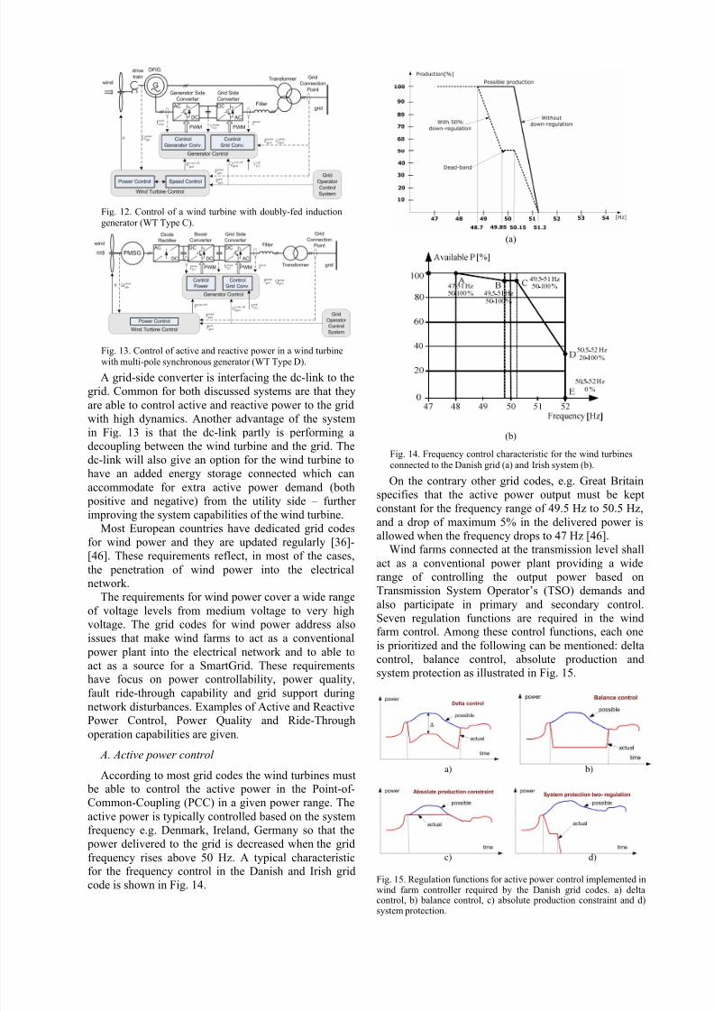
Fig. 12. Control of a wind turbine with doubly-fed induction
generator (WT Type C).
Fig. 13. Control of active and reactive power in a wind turbinewith multi-pole synchronous generator (WT Type D).
A grid-side converter is interfacing the dc-link to the
grid. Common for both discussed systems are that they
are able to control active and reactive power to the grid
with high dynamics. Another advantage of the system
in Fig. 13 is that the dc-link partly is performing a
decoupling between the wind turbine and the grid. The
dc-link will also give an option for the wind turbine to
have an added energy storage connected which can
accommodate for extra active power demand (both
positive and negative) from the utility side – further
improving the system capabilities of the wind turbine.
Most European countries have dedicated grid codesfor wind power and they are updated regularly [36]-
[46]. These requirements reflect, in most of the cases,
the penetration of wind power into the electrical
network.The requirements for wind power cover a wide range
of voltage levels from medium voltage to very high
voltage. The grid codes for wind power address also
issues that make wind farms to act as a conventional
power plant into the electrical network and to able to
act as a source for a SmartGrid. These requirementshave focus on power controllability, power quality,
fault ride-through capability and grid support during
network disturbances. Examples of Active and ReactivePower Control, Power Quality and Ride-Through
operation capabilities are given.
A. Active power control
According to most grid codes the wind turbines must be able to control the active power in the Point-of-
Common-Coupling (PCC) in a given power range. The
active power is typically controlled based on the system
frequency e.g. Denmark, Ireland, Germany so that the
power delivered to the grid is decreased when the grid
frequency rises above 50 Hz. A typical characteristicfor the frequency control in the Danish and Irish grid
code is shown in Fig. 14.
(a)
(b)
Fig. 14. Frequency control characteristic for the wind turbines
connected to the Danish grid (a) and Irish system (b).
On the contrary other grid codes, e.g. Great Britain
specifies that the active power output must be kept
constant for the frequency range of 49.5 Hz to 50.5 Hz,
and a drop of maximum 5% in the delivered power is
allowed when the frequency drops to 47 Hz [46].Wind farms connected at the transmission level shall
act as a conventional power plant providing a wide
range of controlling the output power based on
Transmission System Operator’s (TSO) demands and
also participate in primary and secondary control.
Seven regulation functions are required in the windfarm control. Among these control functions, each one
is prioritized and the following can be mentioned: delta
control, balance control, absolute production and
system protection as illustrated in Fig. 15.
a) b)
c) d)
Fig. 15. Regulation functions for active power control implemented inwind farm controller required by the Danish grid codes. a) deltacontrol, b) balance control, c) absolute production constraint and d)system protection.

8/13/2019 Smartgridand Renewable
http://slidepdf.com/reader/full/smartgridand-renewable 7/10
Fig. 16. Danish grid code demands for the rethe PCC [36], [37].
Fig. 17. Requirements for reactive powerunits without limiting the active powertransmission grid code [55].
B. Reactive power control and volta
Reactive power is typically corange. The grid codes specify in
control capability. The Danish grid
for controlling the reactive power
power output as shown in Fig. 16.
The German transmission grid c
specifies that the wind power un
reactive power provision in thewithout limiting the active power
Fig. 17.
As it can be noticed in Fig. 17 th
possible V-Q profiles depending on
of the transmission system close to
form of voltage control should bewith a time constant in the range of
C. Power Quality
Power quality issues are addre
wind turbines connected to th
networks. However, some grid cod
and Ireland have also requirements
level.
Mainly two standards are used fo
quality parameters namely: IEC 6
50160. Specific values are given f
voltage, short term flicker severit
severity and the total harmonic distoindividual harmonics distortion li
also given based on standards or
ctive power exchange in
provision of generatingoutput in the German
ge stability
trolled in a givendifferent ways this
code gives a band
based on the active
ode for wind power
its must provide a
connection point
output as shown in
re are actually three
the specific strength
the PCC. This basic
ealized very slowlywo minutes [46].
ssed especially for
medium voltage
es, e.g. in Denmark
at the transmission
defining the power
1000-4-30 and EN
r fast variations in
, long term flicker
rtion. A schedule ofits for voltage are
in some cases e.g.
Denmark custom harmonic
defined. Inter-harmonics may
D. Ride through capability
All considered grid codes
capabilities for wind turbine
Voltage profiles are given s
voltage dip and the clearanc problems is that the calculati
types of unsymmetrical fault
in some grid codes. The volt
capability can be summarize
Ireland’s grid code is ver
the fault duration while Den
circuit time duration with o
grid code in Denmark requ
shall remain connected to th
successive faults, which is a
other hand Germany and S
during faults by reactive curr
the rated current.As the power range is in
power systems but also for th
the same demands will be g
they might challenge some o
VII. POWER QUALITY IMP
ELECTRONI
When integrating reneelectrical grid, some situati
stability and even the voltapower injected into the gri
voltage dip occurs, somtechnologies need reactive p
can be supplied by synchrothis solution cannot be
compensation methods are
wind farm, normally near thfarm, to mitigate these proble
Fig. 18. Voltage profile for fault ridgrid codes for wind power [61].
(a)Fig. 19. Reactive power providers. (components: (b) TCR (c) TSC.
compatibility levels are
also be considered.
require fault ride-through
s to overcome grid faults.
ecifying the depth of the
e time as well. One of then of the voltage during all
s is not very well defined
ge profile for ride-through
as shown in Fig. 18.
demanding in respect to
mark has the lowest short
ly 100 ms. However, the
res that the wind turbine
electrical network during
echnical challenge. On the
ain requires grid support
nt injection up to 100% of
reasing not only for wind
e PV systems too, some of
iven to those systems and
the power configurations.
OVEMENT WITH POWER
DEVICES
able energy into thens related to the voltage
ge collapse can limit thed. For example, when a
of the wind turbinewer, which in some cases
ous generators. However,generalized. Dynamic
ften used, both inside the
PCC, or outside the windms [12].
e-through capability in European
(b) (c)) MSC bank; SVC basic

8/13/2019 Smartgridand Renewable
http://slidepdf.com/reader/full/smartgridand-renewable 8/10
Fig. 20. Combination of SVCs. (a) TCR with a fixed capacitor. (b)TCR with TSC.
B. Compensation inside a Wind FarmVoltage stability problems may be derived from the
need of reactive power of some wind turbines. This factbecomes more import during a voltage dip since in this
case, the problem is to generate enough reactive powerfor the wind generators. Some existing solutions for
transient and steady-state voltage control are as follows.1) Mechanical Switched Capacitors (MSCs): This
solution, depicted in Fig. 19(a), consists of a bank of
shunt capacitors switched mechanically to providereactive power compensation. The size of eachcapacitor may be limited in order to avoid large voltage
transients. The main problems in the wind farm are that
the excessive switching of the capacitor bank provokesfailures, applies the inherent voltage steps stress on the
wind turbines, and increases the required maintenanceof the system.
2) SVCs: These systems use thyristor-controlledcomponents, typically thyristor-controlled reactors
(TCRs) and TSCs, also together with MSCs to obtain adynamic controller of reactive power. Normally, SVCs
are connected to the collector bus that connects the
wind farm to the PCC to provide a desired power factoror voltage level. The SVC can adjust the reactivepower, thus to basically solve the steady-state voltage
problems.Fig. 19(b) shows a TCR, which is a device consisting
of three legs, each of them having an inductor and astatic switch. The static switch is formed by two anti-
parallel connected thyristors. The power is controlledby changing the current flow through the inductor by
means of the switch. The ON-state of the thyristors can
be adjusted by the firing angle. However, this devicegenerates current harmonics due to the current
waveform.
A TSC is shown in Fig. 19(c), which consists of abank of switched capacitors. Each capacitor has anindividual static switch, which is similar to a TCR
device, but in this case, the switching takes place whenthe voltage across the thyristor is zero. Consequently,
this device does not produce current harmonics.However, due to the use of switching capacitors, TSC
may produce voltage transients.The combinations between these components can
provide good performances of compensation. Forinstance, TCR can be combined with fixed capacitors or
with TSC, as shown in Fig. 20. In the first case, a TCRis used in combination with a fixed capacitor bank. This
solution is often used for subtransmission and
distribution. The current harmonics may be eliminatedby tuning the fixed capacitors as passive filters.
The second case combines TCR and TSC in onecompensator system. Hence, a continuously variable
reactive power is obtained across the entire controlrange plus full control of both inductive and capacitive
parts of the compensator.3) STATCOM : This system, also named SVC Light by
ABB, is based on a VSC, which is used to generatereactive power. The VSC uses power electronic devices
such as IGBTs, IGCTs, or gate turn-OFF thyristors(GTOs), and they can also be configured as a multilevel
bidirectional converter. As shown in Fig. 21, the VSC isconnected to the grid to inject or absorb reactive power
through an inductor X . This system is suitable to
mitigate both steady-state and transient events.
Compared with SVCs, STATCOMs provide fasterresponse, less disturbances, and better performance at
reduced voltage levels.
Fig. 21. STATCOM based on VSC connected to the PCC through aninductor.
Fig. 22. TCSC. (a) Wind farm connection. (b) Detail of the TCSC.
C. Compensation outside a Wind Farm
In order to send the active power generated by awind farm into the grid, the power transmission control
has to be taking into account. Power oscillations andvoltage collapses should be avoided. Fig. 22 shows a
possible solution to avoid these drawbacks, which usesa thyristor-controlled series compensation (TCSC)
outside the wind farm. The TCSC changes theequivalent capacitor value by switching the parallel-
connected inductor. This way, a variable capacitor canbe obtained and can be adjusted to increase the dynamic
stability of power transmission, improve the voltageregulation and the reactive power balance, and control
the power flow of the grid lines.From Fig. 22(a), it can be seen that the active power
transmitted from the wind farm to the grid and thepower angle can be plotted, as shown in Fig. 23. It can
be observed that the reactance value limits the
maximum power to be transmitted, and enforces alarger power angle that can lead to instabilities and
oscillations. However, if a TCSC is added, both thetotal equivalent impedance of the power line and the
8/13/2019 Smartgridand Renewable
http://slidepdf.com/reader/full/smartgridand-renewable 9/10
power angle can be reduced, thus improving the steady-
state and the transient system behavior. This systemmay be useful for wind farms located far away from the
PCC, such as offshore wind farms.All solutions are useful for providing a more flexible
power system and grid structure towards a SmartGrid
infrastucture
VIII. CONCLUSION The paper discussed a new paradigm of grid
infrastructure where it is moved from being just a
down-streamed, large power producing units to be a
grid structure where the power is dispersed produced –
in many cases closer to the location of consumption.
The most progressing technology is wind power but PV
power plants are also emerging and the technology has
the highest growth rate. The applications of power
electronics in various kinds of wind turbine generation
systems are illustrated showing that the wind turbine
behavior and performance are significantly improved
by using power electronics and will be able to enable a
much more flexible grid structure. Wind turbines areable to act as a contributor to the frequency and voltage
control in the grid by means of active and reactive
power control using power electronics. The same will
be the case for PV power plants. Further, power
electronics devices for enhancing the penetration of
wind power into the grid are presented and discussed.
Thus, power electronics is playing an essential rolewhen integrating renewable technologies like PV and
wind energy systems into the future SmartGrid
structure.
R EFERENCES
[1] J. M. Guerrero, J. C. Vasquez, J. Matas, L. G. Vicuna, M.
Castilla, “Hierarchical control of droop-controlled DC and ACmicrogrids—a general approach towards standardization,” IEEE
Trans Ind Electron., vol. 58, no. 1, Jan. 2011, pp. 158-172.
[2] J. M. Guerrero, F. Blaabjerg, T. Zhelev, K. Hemmes, E.Monmasson, S. Jemei, M. P. Comech, R. Granadino, J. I. Frau,
"Distributed Generation: Toward a New Energy Paradigm,"
IEEE Industrial Electronics Magazine, vol.4, no.1, pp.52-64,March 2010.
[3] A.D. Hansen, F. Iov, F. Blaabjerg, L.H. Hansen, “Review of
contemporary wind turbine concepts and their market
penetration”, Journal of Wind Engineering , 28(3), 2004, pp.
247-263.[4] Z. Chen, E. Spooner, “Grid Power Quality with Variable-Speed
Wind Turbines”, IEEE Trans. on Energy Conversion, 2001, vol.
16, no.2, pp. 148-154.
[5] M.P. Kazmierkowski, R. Krishnan, F. Blaabjerg,”Control in Power Electronics-Selected problems”, Academic Press, 2002.
ISBN 0-12-402772-5.
[6] R. Peña, J.C. Clare, G.M. Asher, “Doubly fed inductiongenerator using back-to-back PWM converters and its
application to variable speed wind-energy generation”, IEE
Trans. on Electronic Power application, 1996, pp. 231-241.[7] K. Wallace, J.A. Oliver, “Variable-Speed Generation Controlled
by Passive Elements”, Proc. of ICEM, 1998, pp. 1554-1559.
[8] J.B. Ekanayake, L. Holdsworth, W. XueGuang, N. Jenkins,“Dynamic modelling of doubly fed induction generator wind
turbines”, IEEE Trans. on Power Systems, 2003, vol. 18, no. 2,
pp. 803-809.[9] F. Blaabjerg, Z. Chen, S.B. Kjaer, “Power Electronics as
Efficient Interface in Dispersed Power Generation Systems”,
IEEE Trans. on Power Electronics, 2004, vol. 19, no. 4, pp.
1184-1194.[10] L. Mihet-Popa, F. Blaabjerg, I. Boldea, “Wind Turbine
Generator Modeling and Simulation Where Rotational Speed is
the Controlled Variable”, IEEE Transactions on Industry
Applications, 2004, vol. 40, no. 1. pp. 3-10.
[11] N. Flourentzou, V.G. Agelidis, G.D. Demetriades, "VSC-BasedHVDC Power Transmission Systems: An Overview," IEEE
Transactions on Power Electronics, vol.24, no.3, pp.592-602,
March 2009.[12] Z. Chen, J.M. Guerrero, F. Blaabjerg, "A Review of the State of
the Art of Power Electronics for Wind Turbines," IEEE
Transactions on Power Electronics, vol.24, no.8, pp.1859-1875,
Aug. 2009.
[13] M. Molinas, J. A. Suul, T. Undeland, "Low Voltage Ride
Through of Wind Farms With Cage Generators: STATCOMVersus SVC," IEEE Transactions on Power Electronics, vol.23,
no.3, pp.1104-1117, May 2008.
[14] M. Zhao, Z. Chen, F. Blaabjerg, "Load flow analysis forvariable speed offshore wind farms," , IET Renewable Power
Generation, vol.3, no.2, pp.120-132, June 2009.
[15] P. Tenca, A.A. Rockhill, T.A. Lipo, P. Tricoli, "Current Source
Topology for Wind Turbines With Decreased Mains Current
Harmonics, Further Reducible via Functional Minimization,"
IEEE Transactions on Power Electronics, vol.23, no.3, pp.1143-1155, May 2008.
[16] M. S. El-Moursi, B. Bak-Jensen, M.H. Abdel-Rahman, "Novel
STATCOM Controller for Mitigating SSR and Damping PowerSystem Oscillations in a Series Compensated Wind Park," IEEE
Transactions on Power Electronics, vol.25, no.2, pp.429-441,
Feb. 2010.[17] R. Li, S. Bozhko, G. Asher, "Frequency Control Design for
Offshore Wind Farm Grid With LCC-HVDC Link Connection,"
IEEE Transactions on Power Electronics, vol.23, no.3, pp.1085-1092, May 2008.
[18] Z. Chen, F. Blaabjerg, J.K. Pedersen, "Hybrid compensation
arrangement in dispersed generation systems," IEEETransactions on Power Delivery, vol.20, no.2, pp. 1719- 1727,
April 2005.
[19] D.S. Oliveira, M.M. Reis, C. Silva, L B. Colado, F. Antunes,B.L. Soares, "A Three-Phase High-Frequency Semicontrolled
Rectifier for PM WECS," IEEE Transactions on Power
Electronics, vol.25, no.3, pp.677-685, March 2010.[20] S. Grabic, N. Celanovic, V.A. Katic, "Permanent Magnet
Synchronous Generator Cascade for Wind Turbine
Application," IEEE Transactions on Power Electronics, vol.23,
no.3, pp.1136-1142, May 2008.[21] A. Prasai, Y. Jung-Sik, D. Divan, A. Bendre, Seung-Ki Sul, "A
New Architecture for Offshore Wind Farms," IEEETransactions on Power Electronics, vol.23, no.3, pp.1198-1204,
May 2008.
[22] F. Iov, P. Soerensen, A. Hansen, F. Blaabjerg, “Modelling,Analysis and Control of DC-connected Wind Farms to Grid”,
International Review of Electrical Engineering , Praise Worthy
Prize, February 2006, pp.10, ISSN 1827-6600.[23] F.K.A Lima, A. Luna, P. Rodriguez, E. H. Watanabe, F.
Blaabjerg, "Rotor Voltage Dynamics in the Doubly FedInduction Generator During Grid Faults," IEEE Transactions on
Power Electronics, vol.25, no.1, pp.118-130, Jan. 2010.
[24] D. Santos-Martin, J.L. Rodriguez-Amenedo, S. Arnaltes,
"Providing Ride-Through Capability to a Doubly Fed Induction
Generator Under Unbalanced Voltage Dips," IEEE Transactions
on Power Electronics, vol.24, no.7, pp.1747-1757, July 2009.[25] Z. Dawei, L. Xu, B.W. Williams, "Model-Based Predictive
Direct Power Control of Doubly Fed Induction Generators,"
I EEE Transactions on Power Electronics, vol.25, no.2, pp.341-351, Feb. 2010.
[26] M. S. El-Moursi, B. Bak-Jensen, M.H. Abdel-Rahman, "Novel
STATCOM Controller for Mitigating SSR and Damping Power
System Oscillations in a Series Compensated Wind Park," IEEE
Transactions on Power Electronics, vol.25, no.2, pp.429-441,
Feb. 2010.[27] J. Dai, D.D. Xu, B. Wu, "A Novel Control Scheme for Current-
Source-Converter-Based PMSG Wind Energy Conversion
Systems," IEEE Transactions on Power Electronics, vol.24,no.4, pp.963-972, April 2009.
[28] X. Yuan, F. Wang, D. Boroyevich, Y. Li, R. Burgos, "DC-link
Voltage Control of a Full Power Converter for Wind Generator
Operating in Weak-Grid Systems," IEEE Transactions on Power Electronics, vol.24, no.9, pp.2178-2192, Sept. 2009.
[29] P. Rodriguez, A. Timbus, R. Teodorescu, M. Liserre, F.Blaabjerg, "Reactive Power Control for Improving Wind
Turbine System Behavior Under Grid Faults," IEEE

8/13/2019 Smartgridand Renewable
http://slidepdf.com/reader/full/smartgridand-renewable 10/10
Transactions on Power Electronics,vol.24, no.7, pp.1798-1801,
July 2009.
[30] F. Blaabjerg, R. Teodorescu, M. Liserre, A.V. Timbus,"Overview of Control and Grid Synchronization for Distributed
Power Generation Systems," IEEE Transactions on Industrial
Electronics, vol.53, no.5, pp.1398-1409, Oct. 2006.[31] A.Timbus, M. Liserre, R. Teodorescu, P. Rodriguez, F.
Blaabjerg, "Evaluation of Current Controllers for Distributed
Power Generation Systems," IEEE Transactions on Power Electronics, vol.24, no.3, pp.654-664, March 2009.
[32] M. Liserre, F. Blaabjerg, S. Hansen, "Design and control of an
LCL-filter-based three-phase active rectifier," IEEETransactions on Industry Applications, vol.41, no.5, pp. 1281-
1291, Sept.-Oct. 2005.
[33] P. Rodriguez, A.V. Timbus, R. Teodorescu, M. Liserre, F.Blaabjerg, "Flexible Active Power Control of Distributed Power
Generation Systems During Grid Faults," IEEE Transactions on
Industrial Electronics, vol.54, no.5, pp.2583-2592, Oct. 2007.[34] L. Maharjan, S. Inoue, H. Akagi, J. Asakura, "State-of-Charge
(SOC)-Balancing Control of a Battery Energy Storage System
Based on a Cascade PWM Converter," IEEE Transactions on Power Electronics, vol.24, no.6, pp.1628-1636, June 2009.
[35] R. Teodorescu, F. Blaabjerg, "Flexible control of small wind
turbines with grid failure detection operating in stand-alone and
grid-connected mode," IEEE Transactions on Power
Electronics, vol.19, no.5, pp. 1323- 1332, Sept. 2004.
[36] EnergiNet – Grid connection of wind turbines to networks withvoltages below 100 kV, Regulation TF 3.2.6, May 2004, pp. 29.
[37] Energinet - Grid connection of wind turbines to networks with
voltages above 100 kV, Regulation TF 3.2.5, December 2004, pp. 25.
[38] ESB Networks – Distribution Code, version 1.4, February 2005.
[39] CER – Wind Farm Transmission Grid Code Provisions, July2004.
[40] E.ON-Netz – Grid Code. High and extra high voltage, April
2006.[41] VDN – Transmission Code 2003. Network and System Rules of
the German Transmission System Operators, August 2003.
[42] VDN – Distribution Code 2003. Rules on access to distributionnetworks, August 2003.
[43] REE – Requisitos de respuesta frente a huecos de tension de las
instalaciones de produccion de regimen especial, PO 12.3,
November 2005.[44] ENEL – DK 5400 - Criteri di allacciamento di clienti alla rete
AT della distribuzione, October 2004.[45] ENEL – DK 5740 - Criteri di allacciamento di impianti di
pr oduzione alla rete MT di ENEL distribuzione, February 2005.
[46] M. Altin, O. Goksu, R. Teodorescu, P. Rodriguez, B. Bak-Jensen, L. Helle, "Overview of recent grid codes for wind power
integration," Proc. of OPTIM’2010, pp.1152-1160, 2010.
[47] T. Shimizu, M. Hirakata, T. Kamezawa, H. Watanabe,“Generation Control Circuit for Photovoltaic Modules“, IEEE
Trans. on Power Electronics, 2001, vol. 16, no. 3, pp. 293-300.[48] B. Yang; W. Li, Y. Zhao, X. He; , "Design and Analysis of a
Grid-Connected Photovoltaic Power System," , IEEE
Transactions on Power Electronics, vol.25, no.4, pp.992-1000,April 2010.
[49] Y. Sozer, D.A. Torrey, "Modeling and Control of Utility
Interactive Inverters," IEEE Transactions on Power Electronics,vol.24, no.11, pp.2475-2483, Nov. 2009.
[50] K. Jung-Min, K. Bong-Hwan, N. Kwang-Hee, "Three-Phase
Photovoltaic System With Three-Level Boosting MPPTControl," IEEE Transactions on Power Electronics, vol.23,
no.5, pp.2319-2327, Sept. 2008.
[51] M. Liserre, R. Teodorescu, F. Blaabjerg, "Stability of photovoltaic and wind turbine grid-connected inverters for a
large set of grid impedance values," IEEE Transactions on
Power Electronics, vol.21, no.1, pp. 263- 272, Jan. 2006.[52] M. Ciobotaru, V. G. Agelidis, R. Teodorescu, F. Blaabjerg,
"Accurate and Less-Disturbing Active Antiislanding Method
Based on PLL for Grid-Connected Converters," IEEETransactions on Power Electronics, vol.25, no.6, pp.1576-1584,
June 2010.
[53] M. Liserre, F. Blaabjerg, R. Teodorescu, "Grid Impedance
Estimation via Excitation of LCL -Filter Resonance," IEEETransactions Industry Applications, vol.43, no.5, pp.1401-1407,
Sept.-oct. 2007.[54] R. Teodorescu, F. Blaabjerg, M. Liserre, P.C. Loh,
"Proportional-resonant controllers and filters for grid-connected
voltage-source converters," IEE Proceedings - Electric Power
Applications, vol.153, no.5, pp.750-762, September 2006.
[55] J.W. Kimball, P.T. Krein, "Discrete-Time Ripple CorrelationControl for Maximum Power Point Tracking," IEEE
Transactions on Power Electronics, vol.23, no.5, pp.2353-2362,
Sept. 2008.[56] L. Asiminoaei, R. Teodorescu, F. Blaabjerg, U. Borup, "A
digital controlled PV-inverter with grid impedance estimation
for ENS detection," IEEE Transactions on Power Electronics,
vol.20, no.6, pp. 1480- 1490, Nov. 2005.
[57] W. Kleinkauf, G. Cramer, and M. Ibrahim, "PV Systems
Technology - State of the art developments and trends in remoteelectrification," SMA Technologie AG, Dec. 01, 2005.
[58] M. Calais, V. Agelidis, "Multilevel converters for single-phase
grid connected photovoltaic systems, an overview," in proc. ofIEEE - International Symposium on Industrial Electronics,
ISIE’08, 1998, pp. 224-229.
[59] N. Jenkins, "Photovoltaic systems for small-scale remote power
supplies," Power Engineering Journal , vol. 9, no. 2, Apr. 1995,
pp. 89-96.
[60] M. Svrzek, G. Sterzinger, "Solar PV Development: Location ofEconomic Activity," Renewable Energy Policy Report 2005.
[61] IEA-International Energy Agency; "Trends in Photovoltaic
Applications: Survey report of selected IEA countries between1992 and 2006"; Report IEA-PVPS T1-16:2007, 2007.
[62] IEA-International Energy Agency, "Trends in Photovoltaic
Applications: Survey report of selected IEA countries between1992 and 2007", Report IEA-PVPS T1-17:2008, 2008.
[63] EPIA, "Global market outlook for photovoltaics until 2013",
European Photovoltaic Industry Association, 2009.


![Resources [renewable and non renewable]](https://static.fdocuments.us/doc/165x107/55643cd7d8b42ad3308b522b/resources-renewable-and-non-renewable.jpg)


![[PPT]Chapter 18 Renewable Energy 18-1 Renewable …environmentalscienceclass.weebly.com/.../ch_18_notes.ppt · Web viewChapter 18 Renewable Energy 18-1 Renewable Energy Today Renewable](https://static.fdocuments.us/doc/165x107/5b029fb97f8b9a6a2e900bdf/pptchapter-18-renewable-energy-18-1-renewable-envir-viewchapter-18-renewable.jpg)