SmartGauge Owners/Installation manual · SmartGauge Owners/Installation manual ... refer to the...
29
SmartGauge Owners/Installation manual This manual applies to software revision r1.08, r1.09, r1.10, r1.11, r1.12, R2.01, R2.02, R2.03, R2.04 We have been forced to add the following warning to this manual. WARNING. Incorrect installation of this product may result in serious damage to the unit which will NOT be covered under warranty. Pay particular attention to the following:- Incorrect battery polarity should not affect the unit. It simply will not work. However, if used in conjunction with the SmartBank Standard or SmartBank Advanced, incorrect battery polarity will almost certainly damage one or both units. Such installation leaves very distinct tell tale signs in both units and will NOT be covered under warranty. Use of the incorrect type of communications cable between SmartGauge and SmartBank may damage one or both units. Such damage will NOT be covered under warranty. No matter how careful you think you are NEVER attempt to carry out any work, whether installation or modification, to any live electrical circuits. Disconnect ALL forms of power before doing any installation or modification work. Failure to adhere to this simple rule will almost certainly result in damage to the equipment which will NOT be covered under warranty. It only takes one simple slip with a screwdriver or wire for just one nanosecond to do several hundred pounds-worth of damage. Opening the case will void the warranty. Remember, we designed this product. We know it inside out, we know what every single component does and know exactly what can cause what symptoms. If the unit is damaged as a result of incorrect installation we WILL know and will NOT cover it under warranty. Please, for your own benefit, heed these warnings. 1
Transcript of SmartGauge Owners/Installation manual · SmartGauge Owners/Installation manual ... refer to the...
SmartGauge Owners/Installation manual
This manual applies to software revision r1.08, r1.09, r1.10, r1.11, r1.12, R2.01, R2.02, R2.03, R2.04
We have been forced to add the following warning to this manual.
WARNING. Incorrect installation of this product may result in serious damage to the unit which will NOT be covered under warranty.
Pay particular attention to the following:-
Incorrect battery polarity should not affect the unit. It simply will not work. However, if used in conjunction with the SmartBank Standard or SmartBank Advanced, incorrect battery polarity will almost certainly damage one or both units. Such installation leaves very distinct tell tale signs in both units and will NOT be covered under warranty.
Use of the incorrect type of communications cable between SmartGauge and SmartBank may damage one or both units. Such damage will NOT be covered under warranty.
No matter how careful you think you are NEVER attempt to carry out any work, whether installation or modification, to any live electrical circuits. Disconnect ALL forms of power before doing any installation or modification work. Failure to adhere to this simple rule will almost certainly result in damage to the equipment which will NOT be covered under warranty. It only takes one simple slip with a screwdriver or wire for just one nanosecond to do several hundred pounds-worth of damage.
Opening the case will void the warranty.
Remember, we designed this product. We know it inside out, we know what every single component does and know exactly what can cause what symptoms. If the unit is damaged as a result of incorrect installation we WILL know and will NOT cover it under warranty.
Please, for your own benefit, heed these warnings.
1
Quick installation guide
This quick installation guide assumes SmartGauge is being installed for the first time. If this is not the case, refer to the main section of this owners manual as the power up sequence will be different.
1. By reference to the diagram below run a cable (1 mm sq minimum) from the battery negative post to the terminal marked GND in the diagram. This cable MUST go to the battery post. NOT to bus bars, isolation switches, fuse panels, current shunts etc.
2. Run a 1 mm sq cable from the B1 terminal on SmartGauge to the battery positive post of the auxiliary battery bank. This cable must have a fuse rated at 3 amps fitted as close to the battery as possible (but not inside the battery compartment) This cable MUST go to the battery post, NOT to bus bars, isolator switches, fuse panels, shunts or distribution panels.
3. If a second battery is to be monitored for voltage run another 1 mm sq cable from the B2 terminal on SmartGauge to the positive battery post of the second battery bank.. This cable must have a fuse fitted rated at 3 amps as close to the battery as possible (but not inside the battery compartment)
After first displaying the software and battery model revisions, SmartGauge will then show “bt 1” in the display and the PGM/Batt 2 LED will be flashing. Use the Status/Select button to scroll this value up to the battery type that corresponds with the battery type of the auxiliary battery bank according to the following:-
Number-Battery type
1 Deep cycle, wet cell, antimony lead acid2 Gel Cell lead acid (a type of VRLA – Valve Regulated Lead Acid)3 AGM – Absorbed Glass Matt (another type of VRLA)4 Hybrid – calcium/antimony (usually marked as dual purpose or “leisure”) lead acid5 Carbon Fibre lead acid6 Maintenance free (wet cells but no way to top up the electrolyte) lead acid
NOTE There are actually two very distinct types of AGM batteries with very different operational characteristics. In one type the only real difference is that the electrolyte is held in a glass matt. This type usually have charge voltages very similar to flooded wet cell batteries. The off load terminal voltages will also be very similar to flooded wet cell batteries. If your AGM batteries are of this type then SmartGauge should be set to battery type 1
The other type of AGM has additional chemicals in the battery (similar to gel cell batteries) and this type usually require lower charge voltages and the off load terminal voltages will be similar to gel cells. This type require SmartGauge to be set to battery type 3. Please note that there has been some discussion recently on the internet stating that there is only one type of AGM battery. Please ignore it. They are wrong and do not know what they are talking about. A quick internet search for the data sheets for various AGM batteries will clearly show batteries with two distinctly different recommended charge voltages and two distinctly different voltage vs state of charge graphs.
When the required type is in the display, simply press Volts (set) or Batt 2 (exit)
The display will now be showing the battery voltage, pressing Batt 2 will display the voltage on the second battery and the PGM/Batt 2 LED will be lit.
Pressing the Status button will display the charge status as a percentage from 0 to 100. This will initially be showing 75% which may or may not be correct. If you know what the charge status of the battery is you can manually set this to correspond (see the main owners manual) with the batteries. Alternatively, if you are currently using the batteries (i.e. regularly discharging and charging them) you may simply leave SmartGauge to synchronise itself. This will typically take 2 or 3 discharge and recharge cycles.
2

SmartGauge can synchronise itself in one discharge and recharge cycle but in order to do so the discharge has to go below 75% (actual, not displayed) and the charge has to exceed 95% (actual, not displayed). Once either of the these conditions has been met, SmartGauge will synchronise itself and track the battery state of charge from that time onwards. Synchronisation is not an instant effect. It is gradual over a period of time.
If a SmartBank is being installed (or is already installed) and connected to SmartGauge, simply plug the RJ11 communications cable into the SmartBank socket on SmartGauge and into the remote socket on SmartBank. SmartGauge will auto detect the correct type of SmartBank and display “Sb S” for SmartBank Standard or “Sb A” for SmartBank Advanced.
That completes installation and initial set-up of SmartGauge. For operation and details of further functions such as alarms, error codes, SmartBank options, etc refer to the main section of the owners manual.
3

4
Full set-up and usage details.
Installation
Disclaimer.
The information contained herein relating to installation is for guidance only. It is believed to be correct at the time of writing. It is the installer’s responsibility to ensure compliance with any relevant safety regulations, codes of practice, legal requirements etc. The manufacturers, suppliers, dealers and/or their agents cannot be held responsible for any breach of such requirements as a result of any information contained herein. Installation of SmartGauge implies acceptance of these terms.
The purpose of this manual is to enable the installer to install SmartGauge in a manner that permits it to operate as designed. This manual’s purpose is not to educate the installer on the legal requirements of any particular type of installation. The manufacturer, supplier, dealer and/or their agents cannot know what the final installation will be and therefore cannot possibly know what the legal requirements of such installation may be. These days, particularly in Europe, legal requirements change faster than the weather and it is practically impossible to keep up with such changes.
Installation of SmartGauge is incredibly simple and should be completed in a very short time. Only two connections are required to operate SmartGauge for normal use. A ground connection (battery -ve) and a power feed connection (battery +ve).
Important installation notes (please read all before continuing with installation).
1. B1 = Battery 1 – this must be the main auxiliary/domestic battery bank being monitored. Do not attempt to use SmartGauge to monitor the state of charge of an engine battery. Do not connect B1 to the engine battery. B1 = auxiliary/domestic battery. B2 = another auxiliary/domestic battery OR an engine start battery.
2. Battery 1 and Battery 2 must both be the same nominal voltage. i.e. both 12 volts or both 24 volts. SmartGauge cannot be used on a mixed installation.
3. Battery 1 and Battery 2 MUST share a common negative. It is not possible to install SmartGauge on 2 isolated battery systems or on 2 battery systems with a common positive..
4. Keep the cable run to the batteries as short as possible. And keep the two leads close together,5. Use 1 mm sq cable as a minimum.6. In order to comply with most safety regulations, and standard good practice, a fuse rated at 3 amps
should be fitted in the positive lead as close to the battery as practical but not inside the battery compartment unless the batteries are certified as safe for use in habitable or sealed compartments (i.e. usually Gel cells or AGMs) or unless the batteries are externally vented via their own ventilation system.
7. The feed to SmartGauge battery +ve and –ve really MUST go to the battery posts. It is NOT acceptable to take the feeds from bus bars, distribution panels, fuse panels or isolation switches.
8. The feed to SmartGauge battery +ve and –ve really MUST go to the battery posts. It is NOT acceptable to take the feeds from bus bars, distribution panels, fuse panels or isolator switches. Yes we know that is the same as number 7 but it is VERY important so we thought it wise to repeat it.
9. Once these cables are run from the batteries to SmartGauge, do not be tempted to tack other equipment onto them. These power feeds must be for SmartGauge and ONLY SmartGauge. The voltage as seen at the SmartGauge end of the wires MUST be identical to the voltage at the battery posts. If you connect other equipment to these cables then it will not be the same. If the voltages are not the same, SmartGauge simply will not operate correctly.
10. Points 7, 8 and 9 above are critical.11. Powering other loads from these two cables includes powering equipment for alarm functions. If an
alarm function is being used to power a sounder or light etc, then the alarm equipment must have its own power feed. It is not acceptable to use the power feeds to SmartGauge for any other purpose.
5
12. If SmartGauge is being installed in an installation with an existing ammeter or amp hours counter utilising a current shunt then normally, all equipment would be connected to the load side of the shunt, not to the battery side. This does NOT apply in the case of SmartGauge. Firstly, SmartGauge MUST be connected directly to the batteries in order to function correctly. Secondly, the current drain of SmartGauge is so low that it will not make any difference to the ammeter using the shunt. In any event the current drain of SmartGauge is probably well below the measurement range of the ammeter.
I’m going to repeat part of the above. The power feed to SmartGauge MUST be directly from the battery posts. Even a really good installation could easily suffer a 0.1 volt drop between the battery posts and the distribution panel under heavy load. A poor installation could suffer up to 0.5 volts drop under even moderate loads. The opposite applies during charging. It is imperative that SmartGauge measures the BATTERY voltage and not the distribution panel voltage. Even 0.01 volts can make a huge difference to the operation of SmartGauge. SmartGauge does not care what the voltage is at the distribution panel. It only cares what the voltage is at the battery posts.
Powering up SmartGauge
By referring to the included flow charts you may find a quick glance through this manual, followed by reference to the flow charts is all that is required in order to operate and understand SmartGauge
SmartGauge incorporates non-volatile memory for certain functions. This is a type of computer memory that will retain the information stored in it, indefinitely, even without power. SmartGauge therefore knows whether it has been used before and is simply being switched back on following power failure or whether it is being installed and powered up for the first time. The two different power up sequences result in different functions and displays from SmartGauge.
First time power up
On powering up SmartGauge for the first time the display will show the software revision information.The following are just examples. They are required for troubleshooting.
r1.03 Software revision 1.03b1.05 Battery model revision 1.05
SmartGauge will then display “SC” whilst it performs a System Check of the system battery voltage. SmartGauge will then display “SC12” or “SC24” indicating that it has detected either a 12 or 24 volt system. Refer to the flow chart headed “First time power up or following factory reset” for details of the expected display during a first time power up.
Finally it will display “bt 1” and this is your opportunity to select the battery type. Refer to the section headed “Battery types” for further details. Pressing the Status button will scroll through the available battery types. Pressing the Volts button will select and store the currently displayed battery type, the display will flash 4 times to signify the data has been written to computer memory and finally the display will move on to show the current battery voltage.
That completes the installation and initial set-up.
Pressing the Status button will display the Charge status (see Note 2 in addendum) as a percentage thus “C 75”, pressing the Volts button will revert to displaying battery voltage thus “13.75” (these are just examples). Pressing the Batt 2 button will show the voltage on Battery 2 if SmartGauge has been installed to monitor this battery. The PGM/Batt 2 LED will be lit whenever Battery 2 is being displayed.
To revert to battery one, press the Volts button or the Status button.
You may notice that it is not possible to select “Status” on battery 2.
6

Initially SmartGauge defaults to a charge status of 75%. This will probably be incorrect initially. There are 4 very simple ways this can be corrected…….
1. If you know what the state of charge is (for instance you may know the batteries to be fully charged) you can enter the set-up menu and manually set the charge status to what you know it to be.
2. Charge or discharge the batteries to approach 75%. When the actual state of charge of the batteries and the displayed charge status meet, SmartGauge will be in perfect synchronisation with the batteries and will track the charge status from that time onwards (see Note 2 in addendum).
3. Forget SmartGauge is there for 48 hours. Get on with your life, using your battery system as usual, SmartGauge will automatically catch up over the next few charge and discharge cycles of the battery bank. Unlike all other battery state of charge meters currently available, SmartGauge becomes more accurate the longer it is used. All other battery state of charge meters become less accurate the longer they are used and require repetitive resetting from the user.
4. The last method is to switch on a charger of some sort (mains powered, alternator, wind turbine, it matters not what) and wait until either you know the batteries are fully charged or the charger tells you they are and goes into float. Then manually set the charge status to 100%
SmartGauge is now up and running. That is all there is to it. For further details, and details of the set-up menu, alarm functions etc refer to the remainder of this manual.
Important note
On first powering up SmartGauge it performs the System Check in order to ascertain whether the system is 12 or 24 volt. SmartGauge does this by simply taking 8 voltage readings and averaging them. Then deciding whether this measured battery voltage is indicative of a 12 or 24 volt system. If, at the time of this check, the battery voltage is outside the normal range for these 2 voltage systems then SmartGauge may detect the wrong system. The voltage would have to be wildly out but it could happen that SmartGauge is installed on a 24 volt system with totally flat batteries at say 16 volts instead of around 25 volts. This would result in SmartGauge detecting a 12 volt system.
Likewise SmartGauge may be connected to a 12 volt system with a faulty charger operating at say 19 volts. This would cause SmartGauge to detect a 24 volt system.
If either of these happen, then SmartGauge simply will not operate. Once normal battery voltage is restored SmartGauge will show a permanent HI or LO and an E 04 error. If this happens the only solution is to carry out a “Reset to factory defaults”, ensure the battery voltage is correct, and reapply power.
Power up following power loss
SmartGauge requires a permanent power feed in order to operate. It cannot operate and accurately track the state of charge of the batteries if its power feed is not permanent. Should SmartGauge lose power it will of course shut down. On reapplication of power it will continue where it left off with the following changes.
Charge Status will no longer be accurate. It may be necessary to revert to one of the four methods described under the heading “First time power up” in order to ensure that the actual charge status of the batteries and the charge status as indicated by SmartGauge agree with each other.
If Primary alarms were set to operate on low charge status, then the alarm will have been disabled. Low or high voltage alarms will remain active. All the set points such as voltage or status activate and deactivate levels, low status timer etc will remain as they were, but an actual low status alarm will be switched off. Secondary alarms will remain as they were set prior to the power failure.
The display will alternate between volts and E 01 (error 01 – lost power) until a key is pressed. This is to alert the user to the fact that power has been lost. E 01 will continue to flash forever until a button is pressed, if another error occurs the new error will not take over, E 01 will remain as the priority error. If the
7

display goes into sleep mode the error will always continue to flash. Again this is to alert the user to a problem.
The E 01 error alerts the user to the fact that power has been lost and therefore the charge status may no longer be accurate. This is the sole reason for this error code. Once a button is pressed the display will move on to show something like 2.36 or 17.49 – This is the approximate time in hours and minutes since power was reapplied. It will count up to a maximum of 99 hours and 59 minutes and will then remain at that display, it will not reset or wrap round. This is handy in that if you know when the power was reapplied, it may help you A) identify the problem and B) make a better decision on whether the charge status will need to be reset or whether SmartGauge will have already resynchronised itself.
Note that this time is approximate. The internal clock in SmartGauge is only as accurate as it needs to be in order to calculate the charge status of the batteries. It does not need atomic clock accuracy in order to do so. The time displayed will be accurate to within about 10%
All other functions and settings will remain as they were prior to the power failure. There is no need to reset any other functions. SmartGauge will remember ALL settings (with the exception that status alarms will have been disabled).
Refer to the flow chart headed “Re power up following power failure” for details of the expected display.
Note that re powering up SmartGauge results in a completely different display from when it is first powered up following first installation (or following a reset to factory defaults). In particular it does not carry out the System Check (“SC”) and does not ask for the battery type. Both these parameters are stored in non-volatile memory and will be retained from the previous use.
Also note that following reapplication of power SmartGauge will continue to operate as previously so given time it will catch up with the charge status of the batteries. But remember that a previously set Status alarm will now be switched off.
If for some reason it is required to revert the unit to “as new” status, prior to first installation (perhaps the unit is being moved to a new installation, or someone has been playing with the set-up menu and messed the settings up) then refer to the section headed “Reset to factory defaults”
Basic use
The basic use of SmartGauge is extremely simple. Assuming factory defaults have been left alone and that the initial power up sequence has been followed this is how it will operate.
Pressing the Volts button will display volts on battery 1. Pressing the Status button will display charge status on battery 1 (see Note 2 in addendum). Pressing the Batt 2 button will show the voltage on battery 2 and the PGM/Batt 2 LED will light up solid to show that the current display is not the usual battery 1. To revert to Battery 1 display, press Volts or Status.
2 minutes after pressing any button the display will blank. This is a power saving feature (the display uses more power than the rest of SmartGauge so blanking the display results in a considerable power saving) and SmartGauge will continue to operate, calculating the charge status and monitoring for error conditions, alarms etc. Pressing any button will bring SmartGauge out of sleep mode and the display will once again operate for 2 minutes. Sleep mode is user defeatable. Refer to the section headed “Display Modes” for alternative displays.
If the battery voltage goes outside the measurement range (9 to 17 volts for 12 volt systems, 18 to 34 volts for 24 volt systems), the volts display will show “HI” or “LO” while the voltage remains outside the range. An E 04 error will also be displayed and will remain displayed, to alert the user to a problem, until a button is pressed.
8

If the battery voltage remains below the low voltage warning for the set battery type an E 02 error will be displayed. If the battery voltage remains above the high voltage warning for the set battery type an E 03 error will be displayed.
The high and low voltage warnings described above are preset limits which vary for each battery type. Quite simply, they are the voltage and time limits, outside of which, battery damage may occur or other dangerous conditions may arise such as the production of explosive gasses..
If power is lost an E 01 error will be displayed.
“HI” and “LO” error displays are only shown if the display is currently set to “Volts”. They are not displayed if the display is set to “Status”. They are also not shown if the display has gone into sleep mode. But the resulting E 04 error will remain displayed.
All error codes E 01, E02, E 03 etc are shown whatever mode the display is set to. They are shown even if the display has gone into sleep mode.
The set-up menu
The set-up menu allows the user to adjust and set many of the parameters that SmartGauge uses. These being:-
Battery typeCharge StatusAlarm functionsError code disablingDisplay modesDisplay brightnessLock functionSmartBank functions
If SmartGauge is installed in conjunction with the SmartBank split charge system another menu appears to set-up the functions and parameters for SmartBank. This menu will not appear unless a SmartBank is physically installed and connected to SmartGauge with the communications lead.
Further, some extra functions appear in the SmartGauge set-up menu when a SmartBank is installed. These extra functions do not appear in the menu if SmartBank is not installed.
To enter the set-up menu press both the Volts and Status buttons simultaneously and keep them pressed. After 2 seconds the display will change. If no SmartBank is installed, the display will show “bt x” (battery type x). If a SmartBank is installed the display will show “Su 1” (Set-up menu 1). “Su 1” continues on to the main SmartGauge set-up menu. Selecting “Su 2” will move on to the SmartBank set-up menu. Press the Volts button to choose “Su 1”. Pressing the Status button will change to “Su 2”.
Assuming you selected “Su 1”, you are now in battery type set-up mode. Refer to the section below headed “Set-up mode – Battery type”
In order to simplify use and programming, in all set-up menus there is a fixed convention. This does not vary at any time.
Firstly, when in the set-up menu, the PGM/Batt 2 LED will flash. This is the only time this LED will ever flash. So if you ever see this LED flashing, someone, somewhere, has left SmartGauge in set-up mode. (That actually isn’t entirely true. The PGM/Batt 2 LED will also flash when SmartGauge is showing time since re power up and during the initial power up sequence – in essence, the PGM/Batt 2 LED will flash whenever SmartGauge is not in the normal operation mode).
9
Whilst in set-up mode all internal calculations stop. SmartGauge cannot calculate the charge status of the batteries whilst various parameters are being changed in the set-up menu. A few minutes while you set up an alarm will not matter, SmartGauge will soon catch up. Leaving SmartGauge in set-up mode for long periods of time would mean it would run out of synchronisation with the batteries and either require time to catch up or it would require manual setting of the charge status. For this reason there is a time limit on the set-up menu. Each item to be set will allow approximately 2 minutes for the user to set the function. After this 2 minutes, the currently displayed selection will be written to SmartGauge memory and the set-up menu will be exited. SmartGauge will then revert to normal operation.
The display will never go into sleep mode when in the set-up menu.
When in the set-up menu, the main legends on the buttons are no longer active. Instead the secondary legends are the appropriate functions. The secondary legends are in blue smaller letters underneath the main legends.
Pressing the Select button will scroll the current displayed value or option to the next available one. At the last value, SmartGauge will “wrap round” to the first value and continue. So pressing the Select button will simply scroll round and round all available values indefinitely.
Pressing the Set button will set the displayed value, the display will flash 4 times to show the value has been written to memory. The display will then move on to the next menu item.
Pressing the Exit button does the same as pressing the Set button except that after writing the value to memory, it exits the set-up menu instead of moving on to the next item. This prevents you having to tap buttons all the way through the set-up menu after you have set your desired function.
At any time, when moving onto a new menu item, the existing value (be it alarm voltage set points, battery types, display modes etc) will be displayed first. So simply pressing the Set button will show each selected item without ever changing any of them. This allows you to look through the menu to check all the settings without changing any of them or having to remember what they should be set to. Unless you specifically change a function or parameter with the Select button, nothing will be changed.
Refer to the flow chart headed “SmartGauge set-up menu - no SmartBank installed” for full details of all the functions.
Set-up mode – Battery type
On entering the set-up menu the first item to be set is the battery type, shown as “bt x” where “bt” signifies battery type and “x” shows the current selected type. If this is a first power up, “x” will be 1. Otherwise it will show whatever is the current selected battery type.
The battery types are numbered 1 to 7 and are as follows:-
Note that this is not intended as a full description of battery types. Merely sufficient information to enable you to select the correct battery type for your batteries. If you are unable to identify the battery type from the manual supplied with the batteries the following options will usually yield good results.
A. Telephone the supplier and ask them which of the following groups the batteries best fit into.B. Ask the manufacturer the same question.C. Visit the battery manufacturer’s website where they usually have full technical details of all
battery types (except one very large battery manufacturer whose “technical specifications” page simply shows the battery dimensions and weight!).
Type 1 Standard wet cell deep cycle Lead Acid - also known as Antimony/AntimonyUse this setting for:-
10
1. Standard vented Lead Acid deep cycle2. Lead acid recombinant (have a catalyser in the cap to recombine the oxygen and hydrogen back into water that is normally lost during charging in a standard Lead Acid battery) NOT to be confused with VRLA (AGM or Gel)
Type 2 Gel Cell - a type of VRLA (Valve Regulated Lead Acid or Vented, Recombinant Lead Acid – itdepends who you ask)Use this setting only for Gel CellsNote that there are actually several different types of gel cell batteries. They vary in order to achieve faster recharge times for certain types and some permit a higher charge voltage. These different characteristics do affect your charger settings but they do not affect the operation of SmartGauge. SmartGauge simply needs to know that the batteries are Gel Cells. The actual type of Gel Cell is not important.
Type 3 AGM - Absorbed Glass Matt (another type of VRLA)Use only for genuine AGM batteries. These batteries behave in a completely different way to the other battery types and SmartGauge will not operate correctly with any other setting.
NOTE There are actually two very distinct types of AGM batteries with very different operational characteristics. In one type the only real difference is that the electrolyte is held in a glass matt. This type usually have charge voltages very similar to flooded wet cell batteries. The off load terminal voltages will also be very similar to flooded wet cell batteries. If your AGM batteries are of this type then SmartGauge should be set to battery type 1
The other type of AGM has additional chemicals in the battery (similar to gel cell batteries) and this type usually require lower charge voltages and the off load terminal voltages will be similar to gel cells. This type require SmartGauge to be set to battery type 3
Type 4 HYBRID - Also known as Antimony/Calcium. Often marked as “low maintenance” (NOT maintenance free). These batteries are a compromise between an engine start battery and a true deep cycle battery. They usually have fewer plates than an engine start battery but more than a true deep cycle battery. They also usually use a combination of calcium and antimony in the lead plates (as opposed to just antimony in a true deep cycle battery and just calcium in an engine start battery) and are sometimes labelled as being suitable for leisure AND engine starting (two completely incompatible requirements). They are not a true deep cycle battery (some would argue that they have the disadvantages of both types and none of the advantages) and will not last very long when used for this purpose but they are commonly seen and used (probably because they are much cheaper than deep cycle batteries) and are therefore supported by SmartGauge.
Type 5 Carbon FibreUse only for Carbon Fibre batteries which, again, behave very differently to the other types.
Type 6 Maintenance free, Calcium/Calcium.This type of battery is not designed for deep cycle use but they are commonly used as such (again, probably because they are cheap). They will suffer a very short life when used as such but people continue to use them so SmartGauge supports them.
Type 7 Do not select type 7. This battery type is a customisable battery model for use in special installations and in normal use will keep changing itself to different models. Note that type 7 is not available on first power up. It only appears on the set-up menu after the initial power up sequence..
Also note that there is no setting for engine start batteries. They are totally unsuitable for deep cycle use, will last less than 20 discharge/recharge cycles and are therefore not supported.
11
Set-up mode - Charge Status
Charge status can be manually set to any value between 0 and 100%. In order to do so, enter the set-up menu as usual, then press the Set key until “Cxxx” is displayed. “C” signifying Charge status, the xxx will be the current calculated charge status. Pressing the Select button will scroll up to and including 100 then wrap round to 0 and start again. When the desired value is displayed, press the Volts key. The display will flash as usual to show the value has been stored. The display will then move onto the next menu item....
Alternatively, as usual, pressing the Exit button will write the value to memory then exit the set-up menu.
Set-up mode - Alarm Functions
See the section headed “Alarm outputs” for details of the alarm hardware. This section deals only with setting the alarms in software.
There are two types of alarm incorporated in SmartGauge. The Primary Alarm and the Secondary Alarm. They both operate on the same hardware output but are designed for different purposes. The first is the Primary Alarm which can be set OFF or set to operate on a user programmable low/high voltage or to operate on one of two types of user programmable low charge status.
Set-up mode - Primary Alarm
On entering this section of the set-up menu the display will show “PA x”. PA signifying Primary Alarm. “x” displaying either “O” “ U” “ S”. or “t”. “O” obviously means alarms are switched Off i.e. disabled. “U” means Uoltage alarm is enabled, “S” means low Status alarm is enabled. “t” means a timed low status alarm is enabled. “S” and “t” type alarms are more fully described under their respective headings. The Select button will scroll round them as usual. The Set button will set the desired alarm. The display will flash showing the value was written to memory.
Changing the alarm type will cancel any currently active alarms and reset the timed alarm timers to the users programmed default value.
On selecting “PA O” the display will flash and then move onto the next item in the set-up menu, Secondary Alarms.
Set-up mode - Uoltage alarm
On selecting “PA U” the display will flash as usual to show the value was written to memory.
The display will then show either “Hi” or “Lo”. The Select button will alternate between these two options. “Hi” sets a high voltage alarm. “Lo” sets a low voltage alarm. Pressing set will store the value as usual. The display will flash as usual.
The display will then show “xx.xx” which is the lower voltage trip point.
Once this is set (in the usual manner using the Select and Set buttons) the display will again show “xx.xx” which is the upper voltage trip point.
If a low voltage alarm was set then the lower voltage trip point is the voltage below which the actual battery voltage will have to fall in order to trigger (activate) the alarm output. This is the activation voltage. The factory default for this value is 11.80 volts. Pressing the Select button will scroll this value up to and including 16.50 volts. It will then wrap round to 10.50 volts then continue to scroll upwards. When the desired value is displayed, press the Set button to write the value to memory, the display will flash as usual. The upper voltage trip point is the voltage which the actual battery voltage will have to rise to in order to deactivate the alarm. This is the deactivation voltage. The factory default for this is 13.20 volts. Pressing the Select button will scroll this value up to 16.50 volts, it will then wrap round to whatever value
12

was previously entered for the alarm activation voltage. This means that no matter what you do, SmartGauge will not allow this value to be set lower than the activation voltage. Pressing the Set button will write the value to memory.
If a high voltage alarm was set then the procedure remains identical except the upper voltage trip point is the voltage which the battery voltage will have to rise to in order to activate the alarm. Once the alarm is triggered, the battery voltage will have to fall back down below the lower voltage trip point in order to deactivate the alarm.
The display will then move on to the next item in the set-up menu, secondary alarms.
Remember, at any time in the set-up menu, pressing the Exit button will write the current value to memory then exit the set-up menu.
Clarification.
For a low voltage alarm:-
The battery voltage has to fall below the activation voltage to trigger the alarm.The battery voltage has to rise to the deactivation voltage to kill the alarm.
So if the activation voltage is set to 12.00 volts then the battery voltage will have to fall to 11.99 volts to trigger the alarm.If the deactivation voltage is set to 12.80 volts then the battery voltage will have to rise to 12.80 to cancel the alarm.Although the battery voltage is displayed to a resolution of 0.05 volts (0.1 volts in 24 volt systems), internally it is measured and dealt with to a finer resolution.
16.50 volts may seem very high for a maximum low voltage setting however this is to allow the low voltage alarm to be used for two extra functions. One is as a “charger failure” alarm, the other is to enable the feature to be used to auto-start a generator set feeding a constant current type battery charger and shutting the generator down at the correct time. These chargers are not very common, but anyone using one will greatly appreciate this feature.
For a high voltage alarm:-
The battery voltage has to rise to the deactivation voltage to trigger the alarm.The battery voltage has to fall below the activation voltage to kill the alarm.
Set-up mode - Status alarm
There are 2 distinct types of Low Status alarm.
The first is exactly the same as the Low Uoltage alarm but operates on charge status instead of on battery voltage. So the alarm will activate once the charge status falls below the chosen activation status, and will deactivate once the charge status rises back up to the chosen deactivation status. This type is designated in the display as “PA S”
The “PA S” type alarm is set in exactly the same way as the “PA U” alarm except PA S” is selected instead of “PA U”. i.e. the activation status will be set, followed by the deactivation status. (however see Note 2 in addendum).
Clarification.
The charge status has to fall below the activation status to trigger the alarm.The charge status has to rise to the deactivation status to kill the alarm.
13

The range limits are:-
Activation status = 1 to 75% (it has to fall below this level hence the reason it doesn’t go down to 0%)Deactivation status = activation status to 100%Factory defaults are activation status = 50%, deactivation status = 95%. These would be typical figures used for an auto start gen-set (however see Note 2 in addendum).
The “PA t” alarm is slightly different. If this alarm is set, the alarm will trigger (be activated) once the charge status falls below the activation status. The alarm will remain triggered until the status rises back up to the same activation level but then, once this happens, a timer is started which counts down from the set time period, and when it reaches zero, the alarm is deactivated. The main reason for this type of alarm is to enable an auto start generator set to be started once the charge status falls to a certain level and then run for a certain fixed period (see Note 2 in addendum).
On selecting “PA t” the display will flash as usual to show the value was written to memory. The display will then show “xx” which is the charge status below which the actual battery charge status will have to fall in order to trigger (activate) the alarm output. This is the activation status. The factory default for this value is 50%. Pressing the Select button will scroll this value up to and including 75%. It will then wrap round to 1 and continue to scroll upwards. When the desired value is displayed, press the Set button to write the value to memory, the display will flash as usual. The activation status is now set.
Note that this activation status shares the same memory as that used for the normal low status alarm. So changing one, will change the other.
The display will now show “tx.xx”. This is now the time, in hours and minutes, that the alarm will remain activated for. The default is 4 hours. However, if an alarm of this type is actually active when you enter the set-up menu (i.e. the alarm LED is on), then this figure will be the current time remaining, on the current count down timer, rounded to the nearest 15 minutes. This enables the user to increase or decrease the remaining time for an existing alarm timer run. Pressing the Select button will increase this time in steps of 15 minutes up to a maximum of 9 hours and 45 minutes at which point the display will wrap round to 15 minutes then continue counting up. Once the desired time is reached, pressing the Set button will, as usual, cause the display to flash, the value will be written to memory and the display will move on to the next item in the set-up menu. If an alarm is not active at the time you enter the set-up menu then this time period will become the default time period for all future status timed alarms.
Remember, changing the alarm type will cancel any currently active alarms.
Be aware that if this menu item is entered whilst a timed alarm run is active, and it therefore shows the time remaining on the current run (as opposed to your default run time), then only the time remaining on the current run will be affected. The normal full time for a timed alarm run will not be changed and will remain as you last set it (or at the factory default if no changes have been made). It is not possible to change the default run time whilst a timed alarm run is active.
Note that this timed period is approximate. The internal clock in SmartGauge is only as accurate as it needs to be in order to calculate the charge status of the batteries. It does not need atomic clock accuracy in order to do so. The timed period and the display will be accurate to within about 10%
Also note that internally SmartGauge counts in seconds whereas the display only shows the minutes. It is rounded to the nearest minute so when the display counts down and reaches zero, there could in fact be 30 seconds remaining.
Set-up mode - Alarms – general
Once an alarm is triggered, the alarm output will activate, the Alarm LED on the front panel will illuminate and the display will alternate between its current display (for 3 seconds) and the alarm display (for 1 second). The alarm display will either show “A LU” for Alarm Low Uoltage, “A HU” for Alarm High
14

Uoltage or “A LS” for Alarm Low Status. If “PA t” has been set, then when the alarm triggers, the display will alternate in 2 ways. It will show the current display (3 seconds), then it will show “A Lt” (Alarm Low status timed),(1 second), it will then revert to the normal display (3 seconds), it will then show the time in hours and minutes until the alarm is due to deactivate (for 1 second). Now when the remaining time is high, it might read, say, 9.45. And that could give the user a nasty shock thinking the battery voltage is at 9.45 volts. To distinguish this display from a normal voltage display the time is prefixed with a “t”. So the display would show “t9.45”. Note that when the display reaches 0.00 there could actually be up to 30 seconds remaining. This is because the timer does not display the seconds.Remember, changing the alarm type will cancel any currently active alarms. Alarm set points and timers can be changed, and the existing alarm will remain active. But actually changing the alarm type (such as from low voltage to low status) will cancel the currently active alarm. This is a simple way of cancelling an active alarm.
If the display is in sleep mode then the alarm output will still activate but the alarm status display will not show, however the Alarm LED on the front panel will still light up. Pressing either button will show what type of alarm has activated in case you forget which type you set. And in the case of “PA t” will show the time remaining before deactivation.
Set-up mode - Secondary Alarm
The display will show “SA x”, “SA” signifying Secondary Alarm, “x” showing the current setting. The default is “O”, Off. The purpose of the secondary alarm is to activate the alarm output, perhaps to sound an external audible warning device or warning light in the event of SmartGauge generating one of its several error codes. “x” can be set to any of the following:-
O Off Default. Error codes will never activate the alarm output.U Uoltage Error codes E 02 and E 03 (low or high voltage warnings for selected battery
type) will activate the alarm output. Note that if error codes are disabled (thenext function in the set-up menu) this secondary alarm will not operate.
r range Error code E 04 (measurement range error) will activate the alarm outputP Power lost Error code E 01 (Power lost) will activate the alarm output.A All All error codes. Note that if any error codes are disabled (the next function in the
set-up menu) then the disabled error codes will not activate this alarm. S SmartBank This option only appears in the set-up menu if a SmartBank is installed in
conjunction with SmartGauge. This option allows the Secondary Alarm tobe triggered by SmartBank errors.
Secondary Alarms and Primary Alarms operate independently of each other. They may both be set at the same time. Adjusting or defeating one will not affect the other. But note that there is only one hardware output.
If SmartGauge is being used in conjunction with a SmartBank split charge system, and no alarms have been set then, whenever the Emergency Connect function is invoked, the alarm output will trigger and remain triggered until the emergency connect function times out. If alarms have been set (either primary or secondary) this will not happen. See the notes at the end of this manual.
Set-up mode -Error code defeating
There are as many ways to charge a lead acid battery as there are ways to cook an egg. The purpose of this section is not to describe all such methods of charging or to describe which types of installations are best suited to each type of charger because that would take an entire book. It is to explain why certain error codes can be defeated (disabled) and who may need to defeat them.
99% of installations, particularly those where loads are used at the same time as charging, use what are known as 2 or 3 stage chargers. These chargers use a combination of an initial (the first stage) “constant current” charge cycle (usually referred to as the bulk stage) then switch to a second stage of constant
15
voltage (usually referred to as the acceptance or absorption cycle). Three stage chargers then switch to a third cycle known as “float”.
These types of chargers usually keep to within very well accepted voltage limits during the charge cycle. For instance a typical gel cell charger would provide full charger current during the bulk stage, then switch to a constant voltage acceptance cycle at around 14.2 volts. This is because it is accepted that, under normal use, a gel battery may be permanently damaged at voltages much higher than this. The error code E 03 in SmartGauge is to warn the user that the accepted high voltage limit for each battery type has been exceeded. Note that the actual voltage limit, and the times and cycle limits required to trigger this error code vary for each battery type.
Now most, but not all, people use these 2 or 3 stage chargers. They are the most popular types of chargers and many people believe they are the only type available or at least that they are the only type worth using.
This simply isn’t the case. Some chargers are referred to as “four stage”. This term can actually mean one of three different types of charger. In one type, the fourth stage is a manually triggerable “equalisation” charge which is a deliberate, controlled overcharge at a higher voltage than usual. The purpose of this charge is mainly to remove the sulphate that builds up on the plates of lead acid batteries used with three stage chargers as they age. Another type of four stage charger uses an automatic fourth stage which is a similar thing but triggered automatically at predetermined charge periods and usually at a slightly lower voltage than the manually triggered “equalisation” cycle. Finally some manufacturers describe as four stage chargers a normal three stage charger but maintain that the fourth stage is the charger providing power to the loads via the batteries but without the batteries being run down. We do not consider this to be any different from a three stage charger. All 3 stage chargers have always had this capability. It is just a by-product of the way they operate.
Finally yet another type of 4 stage charging has now appeared. In this type there is a secondary float voltage at a lower level than the standard float voltage. This level is triggered when the batteries have not been used at all for a certain period of time (usually around 24 hours)
Another perfectly acceptable method of charging lead acid batteries (particularly wet cell types) is constant current charging where the batteries are charged at a constant current until a predetermined voltage is reached (often in the region of 15.5 volts or more) at which time the charger is automatically shut off.
Finally there are constant voltage chargers which typically use a very high charge voltage of around 16 volts or more but charge for a much shorter period than a typical 2 or 3 stage charger.
These types of chargers are not common. Particularly in installations where the batteries are charged at the same time as loads are connected. This is simply because the high charge voltages utilised can damage the connected loads. They are usually reserved for installations where all loads are disconnected during charging however they are occasionally used and these chargers will, in all probability, trigger repetitive or continual E 03 error codes in SmartGauge.
For this reason the next setting on the set-up menu allows error codes E 02 and E 03 to be defeated.
The display will show “EC x” signifying Error Codes and “x” being either “1” for error codes enabled (the default) or “O” for error codes disabled. Note that this setting only affects error codes E 02 and E 03. The other error codes will continue to operate.
Note that error code E 02 is a low voltage warning code. The reason this code is also disabled is that users of the types of chargers that may trigger the E 03 error code are usually experienced users who are aware of how far they can push batteries in order to get the maximum usage from them. They are typically professional users who maintain their batteries properly and often run them down to much lower voltages and charge states than most people.
16

If the “Secondary Alarm” function has been set to activate the alarm on E 02 or E 03, or set to activate the alarm on all error codes, and E 02 and E 03 have been disabled then they will no longer trigger the alarm. The remaining error codes will still activate the alarm as programmed.
Set-up mode - Display modes
There are 4 display modes available in SmartGauge (there are 3 standard display modes, the fourth mode is only available if a SmartBank is installed). The modes apply whether the display is showing volts or charge status.
The default factory setting displays for 2 minutes then goes into sleep mode. This mode is signified in the set-up menu as “dt t” meaning display type = timed. This display will remain active for 2 minutes following a button press. It will then go back to sleep. Pressing a button will switch the display back on for another 2 minutes.
The second display mode is “dt A” meaning “display type = Always” where the display will always be on and will never go into sleep mode.
The third display mode is “dt U” meaning “display type = Uoltage” (note as elsewhere in this manual we write U as opposed to V, we really mean V for volts but it cannot be displayed on a 7 segment display so we use U as a reminder) where the display will go into sleep mode, after 2 minutes, as usual, below a certain voltage but will always remain on above a certain voltage. This voltage is actually the upper voltage trip point for the high/low voltage alarm. The factory default setting for this is 13.20 volts (26.40 volts on 24 volt systems). So if this display mode (“dt U”) is selected and the alarm factory defaults have not been adjusted, the display will blank as normal after 2 minutes if the battery voltage is below this level but will always be on above this voltage. This makes sense in so far as if the battery voltage is above this level then clearly the batteries are either being charged or they are incredibly well charged and in either case the extra few milliamps of power consumed is not an issue. It also allows a keen eye to keep watch on the battery charge voltage without having to continually press buttons. But when the charger is switched off you can rest assured that SmartGauge will revert to the minimum required current draw by blanking the display 2 minutes later.
Note that whilst this setting uses the upper deactivation voltage level of the low voltage alarm, the low voltage alarm does not have to be enabled or active for this function to operate. The two functions merely share the same value.
The fourth setting is “dt S” S signifying SmartBank. In this mode the display will blank as usual after 2 minutes but will wake up on all SmartBank activity. This option only appears if a SmartBank is connected to SmartGauge.
To select the display mode, enter the set-up menu as usual, then press the Volts button until “dt x” is displayed. “dt” signifying display type, the x showing either t, A, U or S. Now press the status button to scroll through the three or four values. Press Volts to confirm the choice. The display will flash to show the value has been written to memory. The display will then move onto the next menu item………
Set-up mode - Display brightness
The display brightness is fully adjustable to enable SmartGauge to be used in any light conditions. One of the advantages of this type of display (LED – Light Emitting Diode) as opposed to the other common display (LCD – Liquid Crystal Display) is that they can be read in zero light conditions as well as daylight. To adjust the display brightness enter the set-up menu as detailed above, then press the volts key until “db x” is displayed. “db” signifies display brightness, x indicates the current brightness which will be from 1 to 8. The factory default value is 4. Pressing the Status button will scroll through the values, wrapping back round to 1 when 8 is reached. You will see the brightness change as you scroll round. When you find the brightness level that best suits you press the volts button. The display will flash as usual to show the value has been stored then SmartGauge will move on to the final item in the set-up menu…..
17
Set-up mode – Menu Lock
The last item in the set-up menu will display Loc0. This allows access to the set-up menu to be denied. Pressing Status will alternate between Loc0 (meaning lock is disabled) and Loc1 (meaning lock is enabled). Setting Loc0 will allow SmartGauge to continue to operate exactly as before. Setting Loc1 will prevent future access to the set-up menu. This will prevent “meddlers” from interfering with your carefully chosen settings. All other functions of SmartGauge remain identical. Only access to the set-up menu is denied.
If Loc1 is set, then any future attempts to enter the set-up menu will be completely ignored. In order to unlock SmartGauge it will be necessary to attempt to perform a “reset to factory defaults”. Note the word “attempt”. If the lock is disabled (Loc0), then “reset to factory defaults” will operate as usual. If the lock is enabled (Loc1) then attempting to perform a “reset to factory defaults” will not do so. It will simply unlock the unit to, once again, allow access to the set-up menu.
Error codes and meanings
There are various error codes in SmartGauge. Each one indicating a different problem. These error codes do not indicate a problem with SmartGauge. They indicate a problem with the installation or other equipment such as chargers. Take note of this before calling your SmartGauge supplier. For instance, if you keep getting an E 03 error, this does not mean SmartGauge is faulty, it means your charger is faulty or it is not of the type you thought it was. Call your charger supplier not your SmartGauge supplier.
All error codes Begin “E” followed by a 2 digit number. The first digit is 0 for errors relating to SmartGauge and 1 for errors relating to SmartBank.
With all “E xx” type error codes, the code is displayed alternately with the current display. If the display has gone into sleep mode, the error code will still be displayed. This is to ensure that an error does not go unnoticed simply because the display was asleep.
The error code will continue to be displayed after the fault condition that caused the error has cleared. This means that if, for instance, the charger is intermittently faulty, and occasionally charging at a much higher voltage than it should be, this would force an error E 03 which would remain in the display even after the charger had gone back to functioning correctly. In order to clear the error code simply press any button.
If, whilst an error code is displayed, another error occurs, the new error code will take precedence. The old error code will be lost. That is to say, only one error code will ever be displayed. The previous error will be lost for ever (or at least until it next occurs). The exception to this is the unique case of an E 01 (lost power) error. This error takes precedence over all other errors. That is to say, an E 01 error will remain on the display until cleared by the user.
E 01 Power was lost and reapplied.
This code has already been described. If power to SmartGauge is lost, when it is reapplied SmartGauge has no way of knowing how long power was lost for nor can it know what has happened to the batteries in the meantime. Therefore it has no way of knowing what the battery state of charge is. It therefore alerts the user to this fact by displaying the E 01 error code. E 01 means that the charge status may be incorrect. It also means that any primary status alarms will have been disabled. Alarm set points will still be as they were last set but the actual alarm will be switched off and will remain so until re enabled by the user. Any low voltage alarms or secondary alarms will remain set as they were prior to the power loss.
Pressing any button will clear the E 01 error code. The display will then show the time in hours and minutes since power was reapplied (up to a maximum of 99 hours, 59 minutes). Pressing any button will clear this display. If no button is pressed, the display will time out after 2 minutes then revert to normal operation. Whilst showing the time since re power, the PGM LED will flash.
18

As with all errors, using the Secondary Alarm function described in the section regarding the set-up menu it is possible to set the E 01 error to trigger the alarm output, perhaps to sound an audible alarm or light up a warning light.
E 02 Battery voltage has been below acceptable level for battery type.
Each different battery type has certain voltage and time limits, which, if exceeded, may damage the battery. For instance if a deep cycle lead acid battery experiences a terminal voltage lower than 10.2 volts for any appreciable length of time it may cause serious, immediate, permanent damage to the battery. SmartGauge has different voltage and time limits for each battery type. If this limit is exceeded then SmartGauge will generate an E 02 error. This error will alert the user to the problem. Be aware that if this error code occurs it is an indication of a severe problem in the installation that, if allowed to persist, will eventually destroy the batteries. It is not an indication of a problem in SmartGauge. Note that this error means the voltage and time limits have been exceeded since a button was last pressed. It does not mean they are currently being exceeded. The error is stored after the fault has cleared until the error is cleared by pressing a button.
E 03 Battery voltage has been above acceptable level for battery type.
This is similar to E 02 except in this case it is a high voltage warning. Again the voltage level and time limits vary dependant upon battery type. For instance wet cell antimony/antimony batteries are far more tolerant of high voltage levels than Gel cells and AGM batteries. Wet cell calcium batteries are even more tolerant than antimony/antimony. Wet cell batteries can tolerate 15 volts or more for long periods of time (always assuming the production of explosive gasses is dealt with) whereas even 14.6 volts could severely damage Gel cell or AGM batteries in a very short time.
Again note that this error means the voltage and time limits have been exceeded since the last error was cleared. It does not mean they are currently being exceeded. The error is stored after the fault has cleared until the error is cleared by pressing a button.
Error codes E 02 and E 03 can be disabled by the user. Refer to the section headed “Error code defeating”
E 04 Battery voltage has exceeded the measurement range of SmartGauge.
SmartGauge can accurately measure voltages between 9.00 and 17.00 volts in 12 volt mode and between 18.00 and 34.00 volts in 24 volt mode.
If these limits are exceeded SmartGauge has no way of knowing what the actual voltage is. Also, if these limits are exceeded there is something seriously wrong with the installation. Such extreme voltages simply should not arise. Ever.
HI Battery voltage is above upper measurement limit of 17.00 volts (34.00 volts in 24 volt installations)
LO Battery voltage is below lower measurement limit of 9.00 volts (18.00 volts in 24 volt installations)
Note that Hi and LO errors will clear as soon as the voltage returns to within the measurement range. They will, however, leave an E 04 error code on the display.
Reset to factory defaults
The “reset to factory defaults” has deliberately been made a little cryptic and difficult in order to prevent it happening by accident. We have seen too many other types of units lose all the user settings simply because they were accidentally reset to the factory defaults, simply because it was so easy to do.
19

Here is what you need to do in order to do a full reset on SmartGauge.
1. Disconnect the power feed to SmartGauge (maybe just pull the fuses out – you did fit them didn’t you?).
2. Press both the Volts and Status buttons and keep them pressed.3. Reapply power, still keeping the buttons pressed.4. SmartGauge will display the software revision as usual. Keep the buttons pressed.5. SmartGauge will display the battery model revision as usual. Keep the buttons pressed.6. The display will go blank.7. Remove your fingers from the buttons.8. SmartGauge will flash “Fr” (Factory reset).9. SmartGauge will completely reset its internals to the factory defaults.
SmartGauge will now operate exactly like a new unit on first power up beginning by displaying the software revision.
NOTE – If the set-up menu lock had been set prior to this, then attempting to perform a “reset to factory defaults” will not do so on the first attempt. It will simply disable the menu lock. A second attempt will perform the reset to factory defaults.
Alarm Outputs
The alarm output consists of 3 terminals labelled COM, NC and NO. These stand for Common, Normally Closed and Normally Open. COM is connected internally via a relay to the NC terminal and disconnected from the NO terminal. When an alarm is activated the COM terminal is internally connected to the NO terminal and disconnected from the NC terminal. At no time are NC and NO terminals connected together (break before make).
These three terminals are totally isolated from the rest of SmartGauge which means you can use them for more or less anything within the following constraints:-
1. The maximum voltage between any of the three terminals and/or the DC system to which SmartGauge is connected is 48 volts. Exceeding this voltage may damage SmartGauge, will invalidate the warranty, will probably be in breach of any relevant safety regulations and may endanger life.
2. The maximum permissible current to be carried by the alarm terminals is 500mA (0.5 amps). Exceeding this current may damage SmartGauge and will invalidate the warranty.
If either of these need to be exceeded then simply use the alarm output to operate an external relay with the required specifications.
More details on the low voltage or status alarm
Assuming the low voltage alarm has been enabled it operates as follows:-
Assume the low voltage activation setting is set to 12.00 volts and the deactivation setting is set to 13.20 volts.
The battery voltage is at 12.6 volts. The alarm output is not active. COM is connected to NC. NO is not connected to anything. The alarm LED is unlit.
As the battery voltage falls eventually it will reach 12.00 volts. The alarm output remains as above.
When the battery voltage falls to 11.99 volts (i.e. below the activation level) the alarm output will activate. COM is now connected to NO. NC is not connected to anything. The alarm LED will light up. A sounder connected to the batteries via COM and NO will now beep.
20

As the voltage rises to say 12.80 volts the alarm output remains in this state.
The battery voltage rises to 13.20 volts, the alarm output deactivates, COM is once again connected to NC and NO is connected to nothing. The alarm LED will go off again. The sounder will go silent.
Operation of the standard low status alarm is identical to that of the low voltage alarm except, of course, that it operates on the charge status as opposed to the battery voltage. Timed low status operates slightly differently. (however see Note 2 in addendum).
This completes operation and setting up of SmartGauge.
Operation of SmartGauge in conjunction with the SmartBank split charge system
Full details of operation of SmartGauge in conjunction with SmartBank Standard and SmartBank Advanced split charge systems are contained in the owners manual entitled “SmartGauge-SmartBank combination owners/installation manual”. This manual is supplied with the SmartBank Advanced or is available on the website at the downloads page.
Do’s and Don’ts
Do read the entire manual before calling your dealer for technical support. Just about anything you could need to know is contained in this manual which took considerable time and effort to write.
Do not attempt to switch SmartGauge between 2 battery banks in order to attempt to monitor them both. It will NOT work. At all. SmartGauge needs to be permanently connected to ONE battery bank. If you need to monitor another battery bank, buy another SmartGauge.
Do not assume something in this manual does not apply to your installation. It does. It applies to the SmartGauge, therefore it applies to your installation. This especially applies to the matter of getting accurate battery voltage readings to SmartGauge. The importance of this cannot be over emphasised. SmartGauge MUST have its own power supply DIRECTLY to the battery posts in order for it to operate. It simply will not function correctly if connected to bus bars, fuse terminals, isolator switches etc. It simply will not operate correctly if other equipment is powered from the same supply leads. It will operate, but the charge status and SmartBank operation will be inaccurate.
Do keep SmartGauge permanently connected to the batteries. The amount of current it uses is probably substantially less than the internal self drain of the batteries (and certainly less than your burglar alarm, CO monitor, clocks and other equipment you forgot about).
Do play with the menus and get to know them. You can’t do any harm by messing with them. The worst you can do is stop SmartGauge working correctly. If you get lost in the menus and mess up all the settings simply “reset to factory defaults” and start again. The menus may seem complicated at first but feedback tells us that once the owner has got used to them they realise the logic and simplicity of them. The menus do not change, the operation does not change. The same key presses are used in all menus. Instead of cryptic function numbers, actual letter type “memory joggers” are used. They really are very simple to understand.
21
Addendum
Note 1 - Fleet operator functions.
Many users of the SmartGauge battery monitor, the SmartBank split charge system and the SmartGuard and PowerGuard battery protection systems are fleet operators or builders. Fleet operators often require the ability for the technicians and installers to be able to set various functions and perform certain tasks with the equipment that the fleet drivers cannot. More specifically, the technicians often want to be able to limit what the fleet drivers can do with the equipment.
SmartGauge incorporates some features specifically for this purpose.
The Menu Lock
The menu lock will completely prevent access to the SmartGauge or SmartBank set-up menus. Any attempt to access the menu will be completely ignored. This will prevent fleet drivers from interfering with the technician’s carefully chosen settings.
Simple Operator sheets
In order to remove the requirement for fleet technicians to waste valuable time training drivers in the use of the equipment we have made available on the website (www.smartgauge.co.uk) some very simple operators guides to the use of SmartGauge, SmartBank Standard and SmartBank Advanced. These are simple, single sheet “what does this mean” guides. These will be sufficient for the actual operators of the installations without any requirement for formal training.
Further fleet operator functions are apparent when used in conjunction with the SmartBank split charge system. Details are contained in the SmartBank Advanced owners manual.
Note 2 – Charge Status during charging and discharging
During discharge, SmartGauge can very accurately track the state of charge of the batteries. During this phase of battery usage it is possible, at certain times, for SmartGauge to actually measure the state of charge of the batteries. SmartGauge continually monitors for an opportunity to do so. When the opportunity arises, SmartGauge does so, then uses the results of this measurement to compare with its calculated figures for charge status. SmartGauge then uses this information to adjust its battery model and the SmartGauge algorithm so that future discharge cycles become more and more accurate. This is one of the ways in which SmartGauge automatically adjusts itself to compensate for battery ageing and the consequent reduced battery capacity as they get older. This is also one of the ways in which SmartGauge is so superior to a meter based on the amp hours counting principle. This is a continual process that continues throughout the life of the batteries so that SmartGauge always shows the percentage power remaining as a fraction of the actual currently available battery capacity as opposed to a percentage of what used to be available when the batteries were new.
This is the important phase, this is when one really needs to know the state of charge.
During charging this is not possible due to the presence of the charger preventing SmartGauge ever getting an opportunity to actually measure the charge status. In effect, if it tried, it would be attempting to measure the charge status of the charger. During charging, SmartGauge only shows the calculated charge status as does an amp hours counter however SmartGauge, because it operates on a different principle, calculates a charge status that is much more accurate. For this reason, it is possible that, during the charge cycle, the charge status displayed may not be totally accurate. It will be within 10% of the actual battery charge status. This may seem like nothing (and is infinitely more accurate than an amp hours counter may show which could be literally hundreds of amp hours adrift), but it can have certain consequences.
22

(Note that once discharging commences, SmartGauge will automatically re-synchronise itself within the first few minutes of discharge or within the first 10 minutes of resting if no load is present. SmartGauge, again, uses this information to modify its battery models and algorithm to increase the accuracy of future calculations.)
For this reason it may not be wise to place too much faith in the charge status during charging. SmartGauge will certainly give a very good indication (certainly better than an amp hours counter – and certainly better than a volt meter [which will tell you nothing more than that the batteries are charging]) but it could be that SmartGauge shows the charge status to have reached (as a worst case example) 100% when in actual fact the batteries have only reached 90%.
Not charging to 100% charge state is one of the most common reasons for premature battery failure. Not charging to 100% (or occasionally well in excess of 100%) causes sulfation of the plates which is the main cause of early battery death.
Therefore, as when using any form of charge status meter, if using an intelligent charger, do not shut the charger down when charge status meter indicates 100% charge status. Instead, rely upon the charger, which can reach a much more accurate measurement of when the batteries are actually fully charged.
Also consider the possible results of using the Primary Alarm set to operate on charge status. If this is being used to operate an auto start generator and charger, and the generator is regularly shut down before reaching 100% charge status this, again, will cause the plates to sulphate up.
This is the reason for the option to set the low status alarm to operate for a fixed period of time instead of until reaching a certain charge status. In some installations it may be better to use this option to ensure that the generator is run for a sufficient period of time.
Either way, rest assured that, once discharging commences, SmartGauge will resynchronise itself (whatever the final true charge status that was reached – i.e. it will not simply assume 100% charge status, as many amp hours counters do) and then give a true indication of the charge status throughout the discharge cycle.
Conversely, it may be the case that SmartGauge only reaches 90% charge status during the charge cycle when in actual fact the batteries have reached 100% charge status and the intelligent charger has gone into float charge. If this happens, again SmartGauge will resynchronise itself during the first stage of the discharge cycle.
Whatever happens, whenever SmartGauge “gets it wrong”, SmartGauge realises, corrects itself, and uses the information to modify its battery models and algorithm. An amp hours counter simply “gets it wrong”, does nothing about it, and runs further and further adrift from the true state of charge.
SmartGauge will NOT run out of synchronisation with the batteries.
Important notes regarding the warranty.
This equipment carries a warranty from the manufacturer covering a 2 year period from the date of purchase. The warranty covers faulty materials or workmanship and is limited in so far as any fault in the equipment entitles the owner to a repair or replacement at the discretion of the manufacturer or supplier. No liability can or will be accepted for any loss or expense as a result of the installation or use of this equipment.
The warranty will become void as a result of any abuse of the equipment including in particular but not limited to:-.
1. Opening the case.2. Any form of external damage to the case such as drilled holes (excluding the 4 pre-drilled mounting
holes) etc.
23

3. Use of the equipment in any manner not described in this owners manual.4. Attempted modifications.5. Excess voltage or current as a result of incorrect installation.6. Exceeding the rating of the alarm outputs.7. Attempting to plug any non-approved equipment into the Smart interface socket or using the incorrect
type of communications lead.8. Incorrect installation.
Glossary of SmartGauge terms and displays
A LU Alarm has activated on Low Uoltage.A LS Alarm has activated on Low StatusA HU Alarm has activated on High UoltageA Lt Alarm has activated on Low status timed
Activation voltage The voltage at which the low voltage alarm will activateActivation status The charge status at which the low status alarm will activate
Battery Type SmartGauge allows 6 different battery types numbered1 to 6 in the set up menu. Refer to the section headed“battery type” for further details.
bt x The display when selecting the battery type
Cxxx The display when showing or setting the Charge Status.
Charge Status The state of charge of the battery expressed as a percentageand displayed as C 63 for 63%
dt t The display when setting display mode to timeddt A The display when setting display mode to Always ondt U The display when setting display mode to Uoltagedt S The display when setting display mode to activate on SmartBank activity
Lower voltage trip point The voltage at which the low voltage alarm will deactivate or the high voltagealarm will deactivate.
Upper voltage trip point The charge status at which the low status alarm will deactivate or the highvoltage alarm will activate.
E 01 Error 01 – power has been lost and reapplied.E 02 Battery voltage has been below the minimum voltage.E 03 Battery voltage has been above the maximum voltage.E 04 Battery voltage has been outside the measurement range.
EC x The display when setting error codesOptions beingEC 1 = All error codes enabledEC 0 = E02 and E03 disabled. E01 and E04 enabled
db x The display when setting the display brightness from 1 to 8
HI Battery voltage above measurement range
LO Battery voltage below measurement rangePA O The display when setting alarms OFFPA U The display when setting alarms to low Uoltage
24
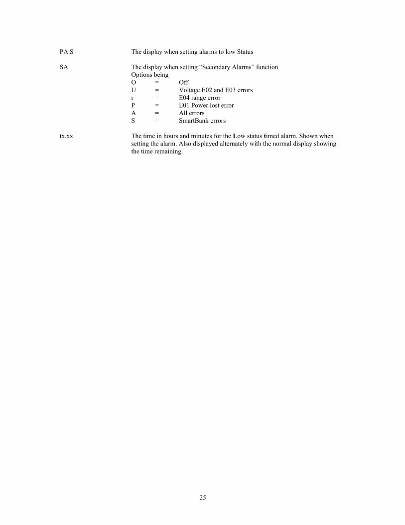
PA S The display when setting alarms to low Status
SA The display when setting “Secondary Alarms” functionOptions beingO = OffU = Voltage E02 and E03 errorsr = E04 range errorP = E01 Power lost errorA = All errorsS = SmartBank errors
tx.xx The time in hours and minutes for the Low status timed alarm. Shown whensetting the alarm. Also displayed alternately with the normal display showingthe time remaining.
25
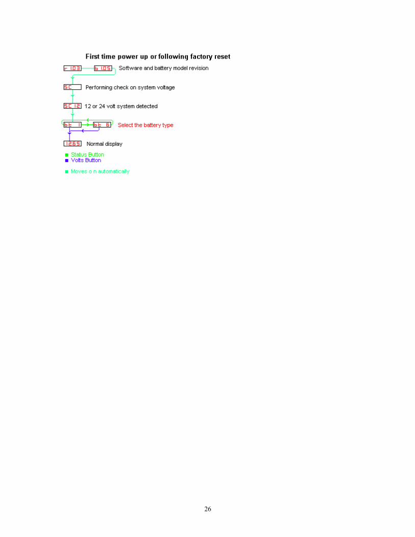
26
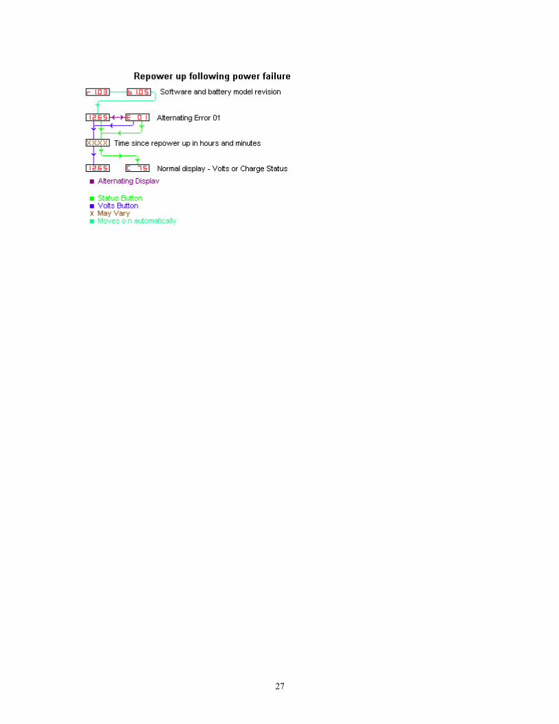
27

28
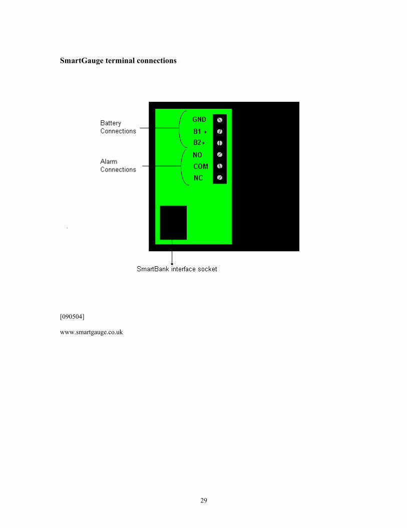
SmartGauge terminal connections
[090504]
www.smartgauge.co.uk
29