
SMARTBRIDGE USER MANUAL
39
SMARTBRIDGE USER MANUAL (model SB020100 RTU MODBUS to LORAWAN CONVERTER Hardware version v02.01.00)
Transcript of SMARTBRIDGE USER MANUAL

SMARTBRIDGE USER MANUAL (model SB020100 RTU MODBUS to LORAWAN CONVERTER
Hardware version v02.01.00)
SB020100 - Smart Bridge LoRaWAN - MODBUS
UMAOC003 Rev E USER MANUAL Page 1 of 38
1. CONTENTS
1. CONTENTS ................................................................................................................................................... 1 2. SAFETY PRECAUTIONS .............................................................................................................................. 2 3. OVERVIEW.................................................................................................................................................... 3 4. INSTALLATION .............................................................................................................................................. 5
4.1. Electrical diagram .................................................................................................................................. 5 4.2. Connectors ............................................................................................................................................ 5
5. COMMISSIONING ......................................................................................................................................... 7 5.1. NFC connectivity ................................................................................................................................... 7 5.2. Setting LoRaWAN communication parameters ..................................................................................... 8
5.2.1. Understanding SmartBridge LoRaWAN profile class ....................................................................... 8
5.2.2 LoRaWAN communication parameters ............................................................................................. 8
5.3 Modbus parameters settings ................................................................................................................. 11 5.3.1 Modbus serial RTU protocol overview .............................................................................................. 11
5.3.2. Table parameter ............................................................................................................................... 11
5.4. Checking the setup and establishing first communication .................................................................. 13 6. OPERATION ................................................................................................................................................ 14
6.1. Internal alarm wakeup ......................................................................................................................... 14 6.2. NFC signal detection ........................................................................................................................... 14 6.3. Modbus values request management ................................................................................................. 14
7. DATA FRAME FORMATS ............................................................................................................................ 16 7.1. UPLINK FRAMES (FROM NODE TO SERVER) ................................................................................ 16
7.1.1. UPLINK 00 (Reading Modbus parameters) ................................................................................... 16
7.1.2. UPLINK 01 (Reading data type and address of the requested group of Modbus registers) ......... 18
7.1.3. UPLINK 02 (Reading slave address and function of the requested group of Modbus registers) .. 19
7.1.4. UPLINK 03 (Serial Modbus RS485 settings) ................................................................................. 20
7.1.5. UPLINK 04 (SmartBridge status) ................................................................................................... 21
7.2. DOWNLINK FRAMES (FROM SERVER TO NODE) .......................................................................... 22 7.2.1. DOWNLINK 01 (Configure Type data and Modbus Address register) ........................................... 22
7.2.2. DOWNLINK 02 (Configure enable parameter, Modbus slave address device and read function) 23
7.2.3. DOWNLINK 03 (Configure Modbus RS485 settings)..................................................................... 24
7.2.4. DOWNLINK 05 (Direct Modbus command to slave) ...................................................................... 25
7.2.5. DOWNLINK 06 (Configure Uplink period) ...................................................................................... 26
7.2.6. DOWNLINK 07 (Configure Time and Date for the SmartBridge) ................................................... 27
7.2.7. DOWNLINK 08 (Next data request for uplink) ............................................................................... 28
8. TROUBLESHOOTING ................................................................................................................................. 29 9. MAINTENANCE AND TECHNICAL SERVICE ............................................................................................ 30
9.1. Battery replacement procedure ........................................................................................................... 30 9.2. Firmware update .................................................................................................................................. 30
10. TECHNICAL FEATURES........................................................................................................................... 32 11. PRODUCT REGULATIONS ....................................................................................................................... 34 12. TRADEMARKS .......................................................................................................................................... 35 13. GUARANTEE ............................................................................................................................................ 36 14. DOCUMENT HISTORY ............................................................................................................................. 37 15. CONTACT INFORMATION ........................................................................................................................ 38

SB020100 - Smart Bridge LoRaWAN - MODBUS
UMAOC003 Rev E USER MANUAL Page 2 of 38
2. SAFETY PRECAUTIONS General considerations:
• Incorrect handling or installation of the unit may result in injury to personnel as well as damage to the
unit or other equipment associated with the system.
• Read the manual carefully prior to connecting the unit. Follow all installation and maintenance instructions throughout the unit’s working life. Pay special attention to the installation standards of the National Electrical Code.
• Do not use the device without the cover on.
• Aonchip recommends using the original cables and accessories that are supplied with the device.

SB020100 - Smart Bridge LoRaWAN - MODBUS
UMAOC003 Rev E USER MANUAL Page 3 of 38
3. OVERVIEW
Modbus protocol is one of the communication standards more extended in the industrial sector. It is easy to find many applications with devices which integrate this protocol like energy meters, programmable logic controllers (PLCs), sensors and so on. The SmartBridge is a device which works as a Master in the Modbus RS485 network and it is able to read and write parameters from the Modbus network through the LoRaWAN communication.
Figure 1.SmartBridge external appearance
LoRaWAN is a very extended internet of things (IOT) protocol so it is possible to integrate the SmartBridge in many platforms to get and manage the data from the device.
Figure 2. Example of integration in a LoRaWAN ecosystem
The SmartBridge is also provided with NFC technology. It means the commissioning process can be carried out in an easy and safe way through any smartphone with NFC technology and using the app SmartBridge Tool.

SB020100 - Smart Bridge LoRaWAN - MODBUS
UMAOC003 Rev E USER MANUAL Page 4 of 38
Figure 3. Status and configuration parameters can be obtained using the NFC technology in smartphones and SmatrBridge Tool app

SB020100 - Smart Bridge LoRaWAN - MODBUS
UMAOC003 Rev E USER MANUAL Page 5 of 38
4. INSTALLATION
4.1. Electrical diagram
Figure 4. Diagram connection for SmartBridge in the RS485 Modbus Network
4.2. Connectors
Figure 5. Connectors location in SmartBridge circuit
J8.1 J8.2 J8.3 J8.4 J8.5

SB020100 - Smart Bridge LoRaWAN - MODBUS
UMAOC003 Rev E USER MANUAL Page 6 of 38
Connector position
Description Electrical value
J8.1 Not used
J8.2 Not used
J8.3 RS485 communication output – signal A From -7V to +12V
J8.4 RS485 communication output – signal B From -7V to +12V
J8.5 Voltage reference for RS485 communication / Shield 0V
SB020100 - Smart Bridge LoRaWAN - MODBUS
UMAOC003 Rev E USER MANUAL Page 7 of 38
5. COMMISSIONING
5.1. NFC connectivity
First step is to configure the equipment to register it in the LoRaWAN network and define the Modbus parameters which must be monitored by the SmartBridge. By default LoRaWAN communication and Modbus parameters are the values used during manufacturing process to guarantee SmartBridge works correctly for delivering to final customer. It is possible to modify the default values via any smartphone with NFC communication. Tapping the cellular over the front of the housing the values can be read and modified with application SmartBridge Tool.
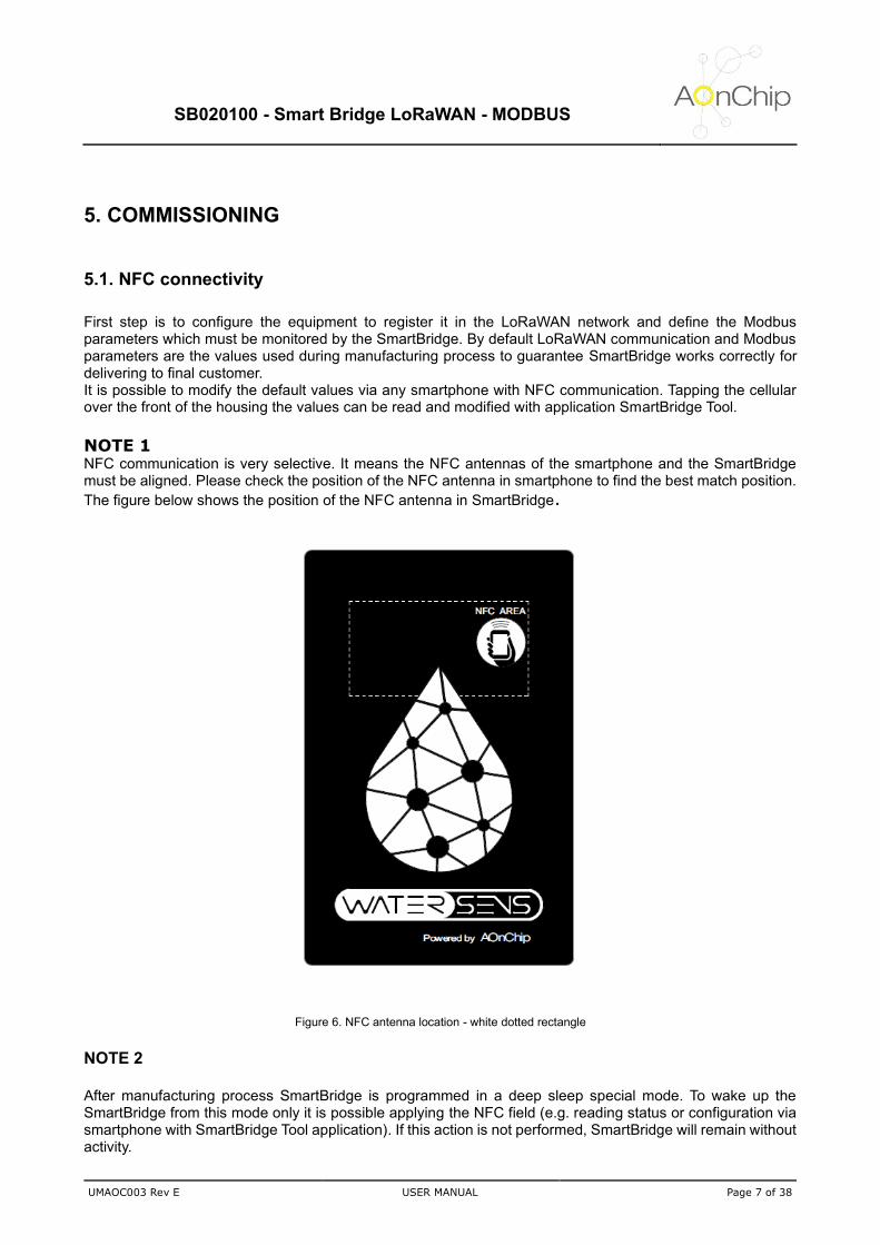
NOTE 1 NFC communication is very selective. It means the NFC antennas of the smartphone and the SmartBridge must be aligned. Please check the position of the NFC antenna in smartphone to find the best match position.
The figure below shows the position of the NFC antenna in SmartBridge.
Figure 6. NFC antenna location - white dotted rectangle
NOTE 2
After manufacturing process SmartBridge is programmed in a deep sleep special mode. To wake up the SmartBridge from this mode only it is possible applying the NFC field (e.g. reading status or configuration via smartphone with SmartBridge Tool application). If this action is not performed, SmartBridge will remain without activity.

SB020100 - Smart Bridge LoRaWAN - MODBUS
UMAOC003 Rev E USER MANUAL Page 8 of 38
5.2. Setting LoRaWAN communication parameters
5.2.1. Understanding SmartBridge LoRaWAN profile class
SmartBridge can be integrated in a LoRaWAN network as a class A device. It means the device implement a bi-directional communication profile in which the data sent by server only can be received by the node after performing an uplink transmission. Is in this moment when the node open two short downlink receive windows as it is shown in the figure below.
Figure 7. Uplink and downlink communication diagram for A class device
This communication profile is the best option to preserve the battery life as it is the profile which the quantity of node transmissions is minimal.
5.2.2 LoRaWAN communication parameters
Time to send data The interval to perform each uplink is defined in minutes. The minimum slot time which can be adjusted is 3 minutes and the maximum is 1400 minutes (once per day). Must be taken into account as lower is the time to uplink less will be the battery life expected. Activation method SmartBridge can be configured in 2 different methods depending on user preferences (security, band occupancy time, etc)
OTAA (Over The Air Activation Method). SmartBridge receive a device address and an authorization token from which to derive sessions keys in combination with AppKey parameter after sending a JOIN request to the server. This method provides high level of security.
ABP (Activation By Personalization). Sessions keys and device network address are predefined. SmartBridge does not send a JOIN request to server but the security level is lower than OTAA method.

SB020100 - Smart Bridge LoRaWAN - MODBUS
UMAOC003 Rev E USER MANUAL Page 9 of 38
Application EUI (AppEUI) This parameter is used in OTAA method. It identifies the application during JOIN request. The length is 8 bytes. Application KEY (AppKey) This parameter is used in OTAA method. It encrypts data during the JOIN request. The length is 16 bytes. Device Address (DevAddr) This parameter is used in ABP method. It is the address in the Lora Network. The length is 4 bytes Device EUI (DevEUI) This parameter is used in ABP and OTAA method. The value cannot be modified (predefined in factory) and it is used to identify the device in Lora Network (it is unique for each device). The length is 8 bytes Application Session Key (AppSKey) This parameter is obtained automatically in OTAA mode, but must be defined by user in ABP mode. The Application Session Key encrypts data during transmission and other applications which can access to the network cannot see the content of messages. The length is 16 bytes. Network Session Key (NwkSKey) This parameter is obtained automatically in OTAA mode, but must be defined by user in ABP mode. The Network Session Key encrypts data during transmission and other networks cannot see the content of messages. The length is 16 bytes. Adaptive Rate Data rate can be adapted automatically by the network (AUTO) or can be adjusted in a fix value by the user (OFF). Data Rate This parameter is the speed at data which is transferred. It can be adjusted by user if adaptive rate is configured as OFF. Depending on the region (EU868, US915, AU915 or AS923) the data rate takes different values.
Table for EU868
DataRate Configuration Indicative physical bit rate [bit/s]
0 SF12 / 125kHz 250
1 SF11 / 125kHz 440
2 SF10 / 125kHz 980
3 SF9 / 125kHz 1760
4 SF8 / 125kHz 3125
5 SF7/125kHz 5470
6 SF7 / 250kHz 11000
7 FSK: 50kbps 50000
8..15 RFU

SB020100 - Smart Bridge LoRaWAN - MODBUS
UMAOC003 Rev E USER MANUAL Page 10 of 38
Table for US915
DataRate Configuration Indicative physical bit rate [bit/s]
0 SF10 / 125kHz 980
1 SF9 / 125kHz 1760
2 SF8 / 125kHz 3125
3 SF7 / 125kHz 5470
5:7 RFU
(visit https://lora-alliance.org/resource-hub/lorawanr-regional-parameters-v102rb for other regions)
Tx Power The output power can be adjusted according to tables below depending on the region (EU868, US915 or AS923). Please, take into account the values indicated in tables are maximum limit values, and device could radiate in equal or lower level.
Table for EU868
TXPower Configuration (EIRP)
0 Max EIRP (**)
1 Max EIRP - 2dB
2 Max EIRP - 4dB
3 Max EIRP - 6dB
4 Max EIRP - 8dB
5 Max EIRP - 10dB
6 Max EIRP - 12dB
7 Max EIRP - 14dB
8..15 RFU
(*) By default Max EIRP (Equivalent Isotropically Radiated Power) is +14 dBm
Table for US915 ()
TXPower Configuration (maximum conducted power)
0 30 dBm – 2*TXpower
1 28 dBm
2 26 dBm
3:9 …
10 10 dBm
11:15 RFU
(visit https://lora-alliance.org/resource-hub/lorawanr-regional-parameters-v102rb for other regions)

SB020100 - Smart Bridge LoRaWAN - MODBUS
UMAOC003 Rev E USER MANUAL Page 11 of 38
Tx Port SmartBridge port for data transmission. Values from 1 to 223 Rx Port SmartBridge port for data reception. Values from 1 to 223
5.3 Modbus parameters settings
5.3.1 Modbus serial RTU protocol overview
Modbus serial RTU is a half-duplex communication protocol which is based on request and answer. The network is composed by a Master and Slave devices and the Master always initiates the communication. For each request launched by the Master is followed by an answer from the slave devices. If slaves does not answer before Timeout(*) is exhausted or slave answers an exception it is considered as an error.
Figure 8. Example of Modbus network over RS485 bus
(*) NOTE The timeout for the SmartBridge is 2s
5.3.2. Table parameter
The SmartBridge can read from the Modbus network up to 20 parameters with 16 or 32 bits length from different slave devices. Each parameter is defined according to the table below.
Parameter Data type (*) Slave address Modbus function Register
address
P1 0-Int16 / 1 -Half Float Nslave (1..254) 03/04 0..65535
P2 0-Int16 / 1 -Half Float Nslave (1..254) 03/04 0..65535
… … … … …
P20 0-Int16 / 1 -Half Float Nslave (1..254) 03/04 0..65535
(*) NOTE Pay special attention in the setting “Data Type” which is linked with the data format obtained after reading the Modbus registers:

SB020100 - Smart Bridge LoRaWAN - MODBUS
UMAOC003 Rev E USER MANUAL Page 12 of 38
If Data Type is configured as 0 (Integer 16 bits) then the SmartBridge gets the value of the register defined by “Register address” setting. The value sent in the uplink frame is the same obtained from the slave device. In case of the Data Type is configured as 1 (Half Float) then the SmartBridge will read a value of 32 bits from the slave device. It means the SmartBridge will read 16 bits from the register defined in the “Register address” and the other 16 bits will be obtained from the consecutive “Register address” (Register address + 1). After getting the 32 bits data (single float 32 bits) it is converted to a 16 bits data (half float) to meet with the maximum length defined for the uplink frame type 00 (Read value from Modbus parameters). This setting is useful when it is needed get more than 4 single registers (16 bits), high resolution is not required and the read parameter will not exceed the value 65504. The figure below shows how data is adapted from single float (32 bits) to half float (16 bits).
Figure 9. Comparison between Single Float and Half float
Silent interval [ms] This is the minimum time to consider no activity in the Modbus network and after that is allowed the communication. This time must be as least 3.5 character according to the Modbus standard. The values can be configured from 1ms to 1000 ms.
Figure 10. Silence interval between Modbus frames
Baudrate Rate of the Modbus network data. Values allowed are 1200, 2400, 4800, 9600, 19200,38400, 57600 and 115200
SB020100 - Smart Bridge LoRaWAN - MODBUS
UMAOC003 Rev E USER MANUAL Page 13 of 38
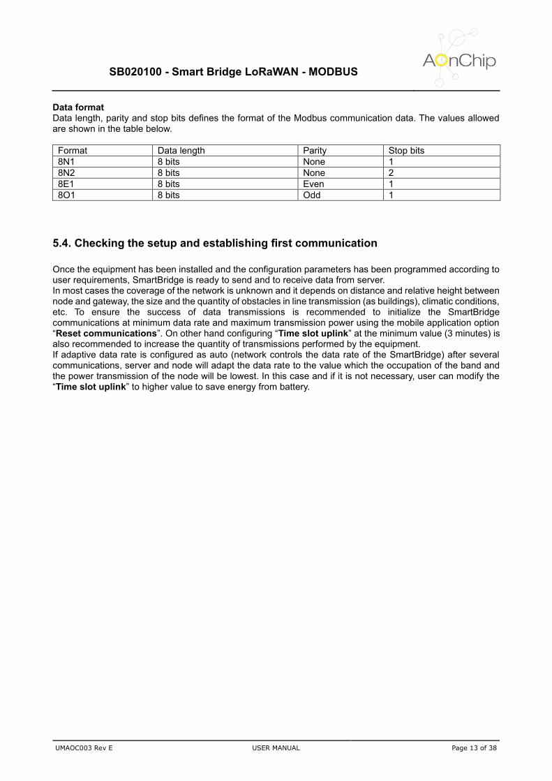
Data format Data length, parity and stop bits defines the format of the Modbus communication data. The values allowed are shown in the table below.
Format Data length Parity Stop bits
8N1 8 bits None 1
8N2 8 bits None 2
8E1 8 bits Even 1
8O1 8 bits Odd 1
5.4. Checking the setup and establishing first communication
Once the equipment has been installed and the configuration parameters has been programmed according to user requirements, SmartBridge is ready to send and to receive data from server. In most cases the coverage of the network is unknown and it depends on distance and relative height between node and gateway, the size and the quantity of obstacles in line transmission (as buildings), climatic conditions, etc. To ensure the success of data transmissions is recommended to initialize the SmartBridge communications at minimum data rate and maximum transmission power using the mobile application option “Reset communications”. On other hand configuring “Time slot uplink” at the minimum value (3 minutes) is also recommended to increase the quantity of transmissions performed by the equipment. If adaptive data rate is configured as auto (network controls the data rate of the SmartBridge) after several communications, server and node will adapt the data rate to the value which the occupation of the band and the power transmission of the node will be lowest. In this case and if it is not necessary, user can modify the “Time slot uplink” to higher value to save energy from battery.
SB020100 - Smart Bridge LoRaWAN - MODBUS
UMAOC003 Rev E USER MANUAL Page 14 of 38
6. OPERATION SmartBridge is a smart Modbus - LoRaWAN protocol adapter which is powered by batteries. To preserve the battery life, it is very important to reduce the power consumption when equipment is not carrying out any task, therefor the SmartBridge enters in sleep mode. SmartBridge exits from sleep mode if internal alarm wakes up the equipment or if it is detected the NFC signal.
6.1. Internal alarm wakeup
SmartBridge wakes up periodically according to the time defined in “Time Slot uplink” with a random time deviation from 0s to +10s. This random time is performed by the control unit to avoid possible collisions for uplinks from other devices units which could send data periodically also. After waking up SmartBridge carries out several tasks:
• Measures battery voltage
• Measures internal temperature
• Get the data from the Modbus network registers configured by the user
• Check if it is the end of the day (00:00h) to update in EEPROM counters (frame counters and other internal parameters)
All these tasks take 30 seconds
6.2. NFC signal detection
When NFC field is detected, SmartBridge wakes up and checks if it is received any command from mobile application. Commands available are:
• Read status parameters
• Read memory configuration (communication and Modbus parameters)
• Write memory configuration (communication and Modbus parameters)
• Time and date synchronization
• Reset communications
• Read Modbus values When the NFC field disappears SmartBridge enters again in sleep mode.
6.3. Modbus values request management
SmartBridge is able to manage up to 20 registers from a Modbus network. These values are sent in sets of 4 registers with an interval of 3 minutes between sets. After sending the 20 registers a new communication will be performed once the “Time Slot uplink” has expired. Finally, if all registers of a set are disabled then the uplink linked with this set will be not sent to avoid not valuable information. The figures below show the details of the process.

SB020100 - Smart Bridge LoRaWAN - MODBUS
UMAOC003 Rev E USER MANUAL Page 15 of 38
Example 1 – all parameters enabled
Figure 11. Modbus communication management example 1
Example 1 – parameters from 5 to 12 disabled
Figure 12. Modbus communication management example 2

SB020100 - Smart Bridge LoRaWAN - MODBUS
UMAOC003 Rev E USER MANUAL Page 16 of 38
7. DATA FRAME FORMATS
7.1. UPLINK FRAMES (FROM NODE TO SERVER)
7.1.1. UPLINK 00 (Reading Modbus parameters)
byte 1 byte 2 byte 3 byte 4 byte 5 byte 6 byte 7 byte 8 byte 9 byte 10 byte 11
tt de xg v1_hi v1_lo v2_hi v2_lo v3_hi v3_lo v4_hi v4_lo
tt. Type of frame (00 - Reading Modbus parameters) de. Data type and parameter enabled indicators
(d). Data type indicator (variable type mask - high nibble) 0x1X - Parameter 1 half float data type 0x2X - Parameter 2 half float data type 0x4X - Parameter 3 half float data type 0x8X - Parameter 4 half float data type 0xFX - All parameters are half float data type
(e). Parameter enabled indicator (variable type mask - low nibble)
0xX1 - Parameter 1 enabled 0xX2 - Parameter 2 enabled 0xX4 - Parameter 3 enabled 0xX8 - Parameter 4 enabled 0xXF - All parameters enabled
Examples
Example 1 - 0x45 - (01000101b)
- Parameters 1 and 3 enabled - Parameter 1 type integer / Parameter 3 type half float
Example 2 - 0x0F - (00001111b)
- All parameters enabled - All parameters type integer
xg. Parameter read error indicator and index register group
(x). Parameter read error indicator (variable type mask - high nibble) 0x1X - Parameter 1 reading error 0x2X - Parameter 2 reading error 0x4X - Parameter 3 reading error 0x8X - Parameter 4 reading error 0xFX - Reading error in all parameters
Example 1 – 0X - (0000XXXXb) - No error Example 2 – 8X - (1000XXXXb) - Error reading parameter 4
(g). Index register group (4 bits data - low nibble)
Example – X2 - (XXXX0010b) – Index group register number 2
SB020100 - Smart Bridge LoRaWAN - MODBUS
UMAOC003 Rev E USER MANUAL Page 17 of 38
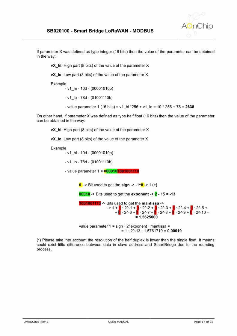
If parameter X was defined as type integer (16 bits) then the value of the parameter can be obtained in the way:
vX_hi. High part (8 bits) of the value of the parameter X
vX_lo. Low part (8 bits) of the value of the parameter X
Example - v1_hi - 10d - (00001010b) - v1_lo - 78d - (01001110b)
- value parameter 1 (16 bits) = v1_hi *256 + v1_lo = 10 * 256 + 78 = 2638
On other hand, if parameter X was defined as type half float (16 bits) then the value of the parameter can be obtained in the way:
vX_hi. High part (8 bits) of the value of the parameter X
vX_lo. Low part (8 bits) of the value of the parameter X
Example - v1_hi - 10d - (00001010b) - v1_lo - 78d - (01001110b)
- value parameter 1 = 0000101001001110
0 -> Bit used to get the sign -> -1^0 -> 1 (+) 00010 -> Bits used to get the exponent -> 2 - 15 = -13 1001001110 -> Bits used to get the mantissa ->
-> 1 + 1 · 2^-1 + 0 · 2^-2 + 0 · 2^-3 + 1 · 2^-4 + 0 · 2^-5 + + 0 · 2^-6 + 1 · 2^-7 + 1 · 2^-8 + 1 · 2^-9 + 0 · 2^-10 =
= 1.5625000 value parameter 1 = sign · 2^exponent · mantissa =
= 1 · 2^-13 · 1.5761719 = 0.00019
(*) Please take into account the resolution of the half duplex is lower than the single float. It means could exist little difference between data in slave address and SmartBridge due to the rounding process.

SB020100 - Smart Bridge LoRaWAN - MODBUS
UMAOC003 Rev E USER MANUAL Page 18 of 38
7.1.2. UPLINK 01 (Reading data type and address of the requested group of Modbus registers)
After receiving the command from the server requesting the addresses of a group of registers SmartBridge will perform in 3 minutes an uplink with this info. The format of the payload is described below
byte 1 byte 2 byte 3 byte 4 byte 5 byte 6 byte 7 byte 8 byte 9 byte 10 byte 11
tt dd gg a1_hi a1_lo a2_hi a2_lo a3_hi a3_lo a4_hi a4_lo
tt. Type of frame (01 - Reading address and data type of the Modbus parameters requested)
dd. Parameter type data indicator (variable type mask - low nibble. Values: 0-integer 16 bits / 1-half float 16 bits)
Example 1 - X3 - (XXXX0011b) - Parameters 1 and 2 defined as half float
- Parameters 3 and 4 defined as integer
Example 2 - X8 - (XXXX1000b)
- Parameters 1, 2 and 3 defined as integer
- Parameters 4 defined as half float gg. Index register group
Example – 02 - (0000010b) – Index group register number 2
aX_hi. High part (8 bits) of the address of the parameter X aX_lo. Low part (8 bits) of the address of the parameter X
Example - a3_hi - 100d - (01100100b) - a3_lo - 15d - (00001111b)
- address of parameter 3 (16 bits) = a3_hi *256 + a3_lo = 100*256+15 = 25615

SB020100 - Smart Bridge LoRaWAN - MODBUS
UMAOC003 Rev E USER MANUAL Page 19 of 38
7.1.3. UPLINK 02 (Reading slave address and function of the requested group of Modbus registers)
After receiving the command from the server requesting the slave addresses and the Modbus function of a group of registers SmartBridge will perform in 3 minutes an uplink with this info. The format of the payload is described below
byte 1 byte 2 byte 3 byte 4 byte 5 byte 6 byte 7 byte 8 byte 9 byte 10 byte 11
tt ee gg slv1 f1 slv2 f2 slv3 f3 slv4 f4
tt. Type of frame (02 - Reading slave address and Modbus function of the Modbus parameters requested)
ee. Parameter enabled indicator
Example 1 - 03d - (00000011b) - Parameters 1 and 2 enabled Example 2 - 15d - (00001111b) - All parameters enabled
gg. Index register group
Example – 03 - (0000011b) – Index group register number 3
slvX. Slave address of the device linked with parameter X (8 bits)
Example - slv3 = 01 - Slave Address 01 for parameter 3
fX. Function to read the value of the parameter X (function 03 or 04)
Example - f2 = 04 - Function 04 to read parameter 2
SB020100 - Smart Bridge LoRaWAN - MODBUS
UMAOC003 Rev E USER MANUAL Page 20 of 38
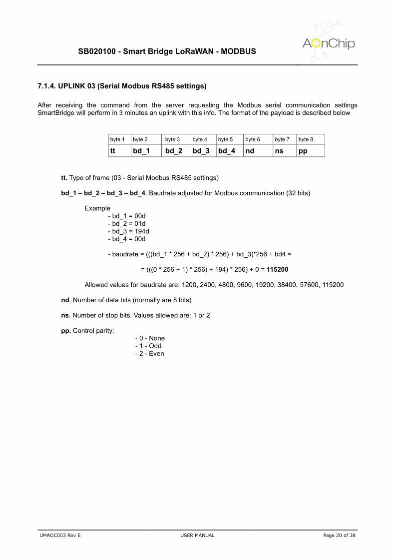
7.1.4. UPLINK 03 (Serial Modbus RS485 settings)
After receiving the command from the server requesting the Modbus serial communication settings SmartBridge will perform in 3 minutes an uplink with this info. The format of the payload is described below
byte 1 byte 2 byte 3 byte 4 byte 5 byte 6 byte 7 byte 8
tt bd_1 bd_2 bd_3 bd_4 nd ns pp
tt. Type of frame (03 - Serial Modbus RS485 settings)
bd_1 – bd_2 – bd_3 – bd_4. Baudrate adjusted for Modbus communication (32 bits)
Example - bd_1 = 00d - bd_2 = 01d - bd_3 = 194d - bd_4 = 00d - baudrate = (((bd_1 * 256 + bd_2) * 256) + bd_3)*256 + bd4 =
= (((0 * 256 + 1) * 256) + 194) * 256) + 0 = 115200
Allowed values for baudrate are: 1200, 2400, 4800, 9600, 19200, 38400, 57600, 115200 nd. Number of data bits (normally are 8 bits) ns. Number of stop bits. Values allowed are: 1 or 2 pp. Control parity:
- 0 - None - 1 - Odd - 2 - Even

SB020100 - Smart Bridge LoRaWAN - MODBUS
UMAOC003 Rev E USER MANUAL Page 21 of 38
7.1.5. UPLINK 04 (SmartBridge status)
After receiving the command from the server requesting the device status SmartBridge will perform in 3 minutes an uplink with this info. The format of the payload is described below
byte 1 byte 2 byte 3 byte 4 byte 5 byte 6 byte 7
tt te mv sn hh mm ss
tt. Type of frame (04 - SmartBridge Status) te. Temperature in ºC (data type 8 bits signed) mv. microcontroller voltage supply in volts x10 (data type 8 bits). Examples:
Voltage OK (>2.8V) - mv = 33 means 3.3V Low battery (<2.8V) - mv = 27 means 2.7V
rr. RSSI of the last link received in dBm data (format signed int) sn. SNR of the last link received in dB data (format signed int)
hh. Hour in time format in 24H mm. Minutes ss. Seconds

SB020100 - Smart Bridge LoRaWAN - MODBUS
UMAOC003 Rev E USER MANUAL Page 22 of 38
7.2. DOWNLINK FRAMES (FROM SERVER TO NODE)
7.2.1. DOWNLINK 01 (Configure Type data and Modbus Address register)
byte 1 byte 2 byte 3 byte 4 byte 5 byte 6 byte 7 byte 8 byte 9 byte 10 byte 11
tt dd gg a1_hi a1_lo a2_hi a2_lo a3_hi a3_lo a4_hi a4_lo
tt. Type of frame (01 - Configure address of the Modbus parameters)
dd. Parameter type data configurator (0-integer 16 bits / 1-half float 16 bits)
Example 1 - 0x03 - (00000011b) - Parameters 1 and 2 defined as half float
- Parameters 3 and 4 defined as integer
Example 2 - 0x08 - (00001000b)
- Parameters 1, 2 and 3 defined as integer
- Parameters 4 defined as half float gg. Index of the group of registers to apply configuration:
Values - 1 – Group Register 1 (from register 1 to register 4) - 2 – Group Register 2 (from register 5 to register 8) - 3 – Group Register 3 (from register 9 to register 12) - 4 – Group Register 4 (from register 13 to register 16) - 5 – Group Register 4 (from register 17 to register 20)
aX_hi. High part (8 bits) of the address of the parameter X aX_lo. Low part (8 bits) of the address of the parameter X
Example - a3_hi - 100d - (01100100b) - a3_lo - 15d - (00001111b)
- address of parameter 3 (16 bits) = a3_hi *256 + a3_lo = 100*256+15 = 25615
SB020100 - Smart Bridge LoRaWAN - MODBUS
UMAOC003 Rev E USER MANUAL Page 23 of 38
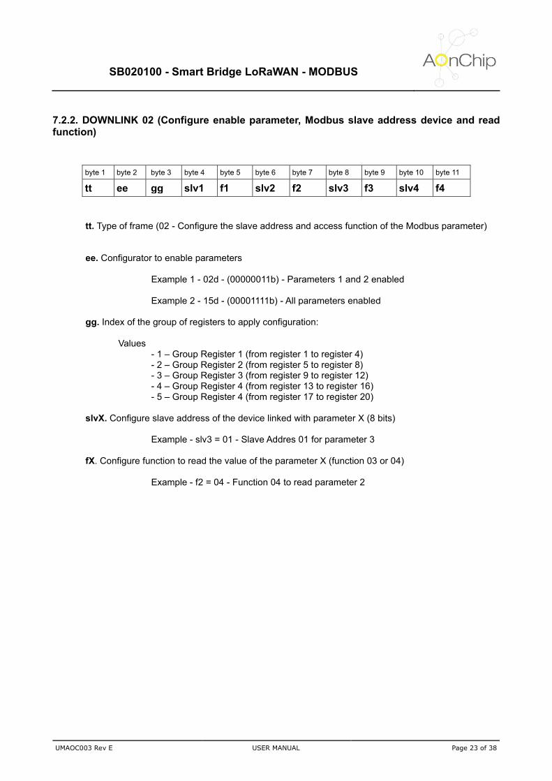
7.2.2. DOWNLINK 02 (Configure enable parameter, Modbus slave address device and read function)
byte 1 byte 2 byte 3 byte 4 byte 5 byte 6 byte 7 byte 8 byte 9 byte 10 byte 11
tt ee gg slv1 f1 slv2 f2 slv3 f3 slv4 f4
tt. Type of frame (02 - Configure the slave address and access function of the Modbus parameter)
ee. Configurator to enable parameters
Example 1 - 02d - (00000011b) - Parameters 1 and 2 enabled Example 2 - 15d - (00001111b) - All parameters enabled
gg. Index of the group of registers to apply configuration:
Values - 1 – Group Register 1 (from register 1 to register 4) - 2 – Group Register 2 (from register 5 to register 8) - 3 – Group Register 3 (from register 9 to register 12) - 4 – Group Register 4 (from register 13 to register 16) - 5 – Group Register 4 (from register 17 to register 20)
slvX. Configure slave address of the device linked with parameter X (8 bits)
Example - slv3 = 01 - Slave Addres 01 for parameter 3
fX. Configure function to read the value of the parameter X (function 03 or 04)
Example - f2 = 04 - Function 04 to read parameter 2
SB020100 - Smart Bridge LoRaWAN - MODBUS
UMAOC003 Rev E USER MANUAL Page 24 of 38
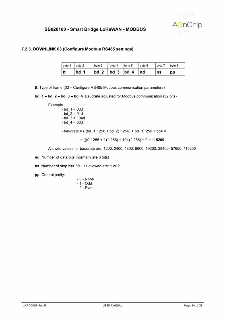
7.2.3. DOWNLINK 03 (Configure Modbus RS485 settings)
byte 1 byte 2 byte 3 byte 4 byte 5 byte 6 byte 7 byte 8
tt bd_1 bd_2 bd_3 bd_4 nd ns pp
tt. Type of frame (03 – Configure RS485 Modbus communication parameters)
bd_1 – bd_2 – bd_3 – bd_4. Baudrate adjusted for Modbus communication (32 bits)
Example - bd_1 = 00d - bd_2 = 01d - bd_3 = 194d - bd_4 = 00d - baudrate = (((bd_1 * 256 + bd_2) * 256) + bd_3)*256 + bd4 =
= (((0 * 256 + 1) * 256) + 194) * 256) + 0 = 115200
Allowed values for baudrate are: 1200, 2400, 4800, 9600, 19200, 38400, 57600, 115200 nd. Number of data bits (normally are 8 bits) ns. Number of stop bits. Values allowed are: 1 or 2 pp. Control parity:
- 0 - None - 1 - Odd - 2 - Even

SB020100 - Smart Bridge LoRaWAN - MODBUS
UMAOC003 Rev E USER MANUAL Page 25 of 38
7.2.4. DOWNLINK 05 (Direct Modbus command to slave)
byte 1 byte 2 byte 3 byte 4 byte 5 byte 6 byte 7 byte 8 byte 9 byte 10 byte 11
tt nn f0 f1 f2 f3 f4 f5 f6 f7 f8
tt. Type of frame (05 - Direct Modbus command to slave) nn. Number of bytes of the frame to send to slave device (maximum 9 bytes) f0..f8. Modbus command to send to slave device without CRC (SmartBridge calculate CRC and add the 2 extra bytes in the frame to send to slave)
Example - Send write single register command for slave device 03, address register 256, value 1024.
tt- 05 nn - 06 f0 - 03 (slave address) f1 - 06 (write single register) f2 + f3 - 01 00 (address register 256) f4 + f5 - 04 00 (value 1024) Payload frame - 05 06 03 06 01 00 04 00

SB020100 - Smart Bridge LoRaWAN - MODBUS
UMAOC003 Rev E USER MANUAL Page 26 of 38
7.2.5. DOWNLINK 06 (Configure Uplink period)
byte 1 byte 2 byte 3
tt tt_hi tt_lo
tt. Type of frame (06 - Configure uplink time period) tt_hi. High part of the value to configure the slot time between uplinks tt_lo. Low part of the value to configure the slot time between uplinks
Example - configure 180 minutes as slot time between uplinks
time = tt_hi *256 + tt_lo = 180
Payload frame -> 06 00 B4
(*) The uplink period can be configured from 3 to 1400 minutes

SB020100 - Smart Bridge LoRaWAN - MODBUS
UMAOC003 Rev E USER MANUAL Page 27 of 38
7.2.6. DOWNLINK 07 (Configure Time and Date for the SmartBridge)
byte 1 byte 2 byte 3 byte 4 byte 5 byte 6 byte 7 byte 8
tt hh mm ss ww dd mn yy
tt. Link type of configuration (07. Time and date adjustment) hh. Hours in format in 24H mm. Minutes ss. Seconds ww. Day of the week
01 – Monday 02 - Tuesday … 07 –Sunday
dd. Day of the month (1..31) mn. Month of the year
01 – January 02 – February … 12 –December
yy Two last digits of the year (2018 → 18)
SB020100 - Smart Bridge LoRaWAN - MODBUS
UMAOC003 Rev E USER MANUAL Page 28 of 38
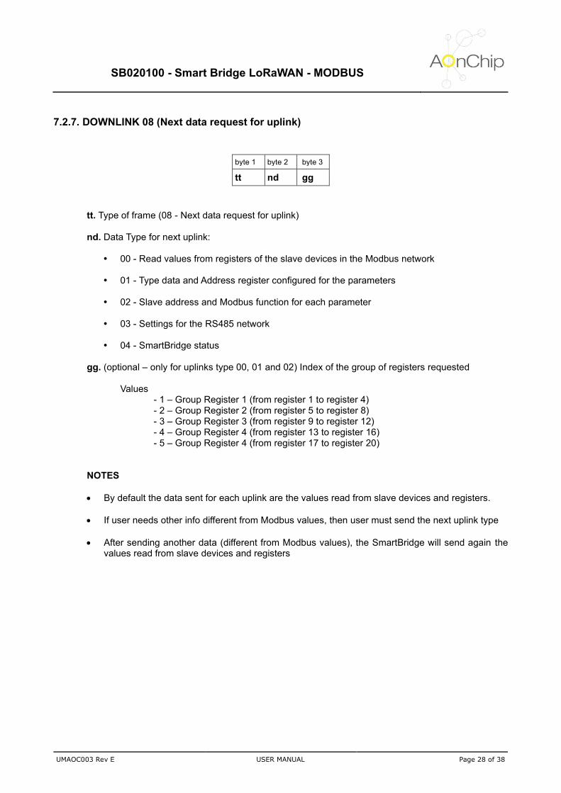
7.2.7. DOWNLINK 08 (Next data request for uplink)
byte 1 byte 2 byte 3
tt nd gg
tt. Type of frame (08 - Next data request for uplink) nd. Data Type for next uplink:
00 - Read values from registers of the slave devices in the Modbus network
01 - Type data and Address register configured for the parameters
02 - Slave address and Modbus function for each parameter
03 - Settings for the RS485 network
04 - SmartBridge status gg. (optional – only for uplinks type 00, 01 and 02) Index of the group of registers requested
Values - 1 – Group Register 1 (from register 1 to register 4) - 2 – Group Register 2 (from register 5 to register 8) - 3 – Group Register 3 (from register 9 to register 12) - 4 – Group Register 4 (from register 13 to register 16) - 5 – Group Register 4 (from register 17 to register 20)
NOTES
• By default the data sent for each uplink are the values read from slave devices and registers.
• If user needs other info different from Modbus values, then user must send the next uplink type
• After sending another data (different from Modbus values), the SmartBridge will send again the values read from slave devices and registers
SB020100 - Smart Bridge LoRaWAN - MODBUS
UMAOC003 Rev E USER MANUAL Page 29 of 38
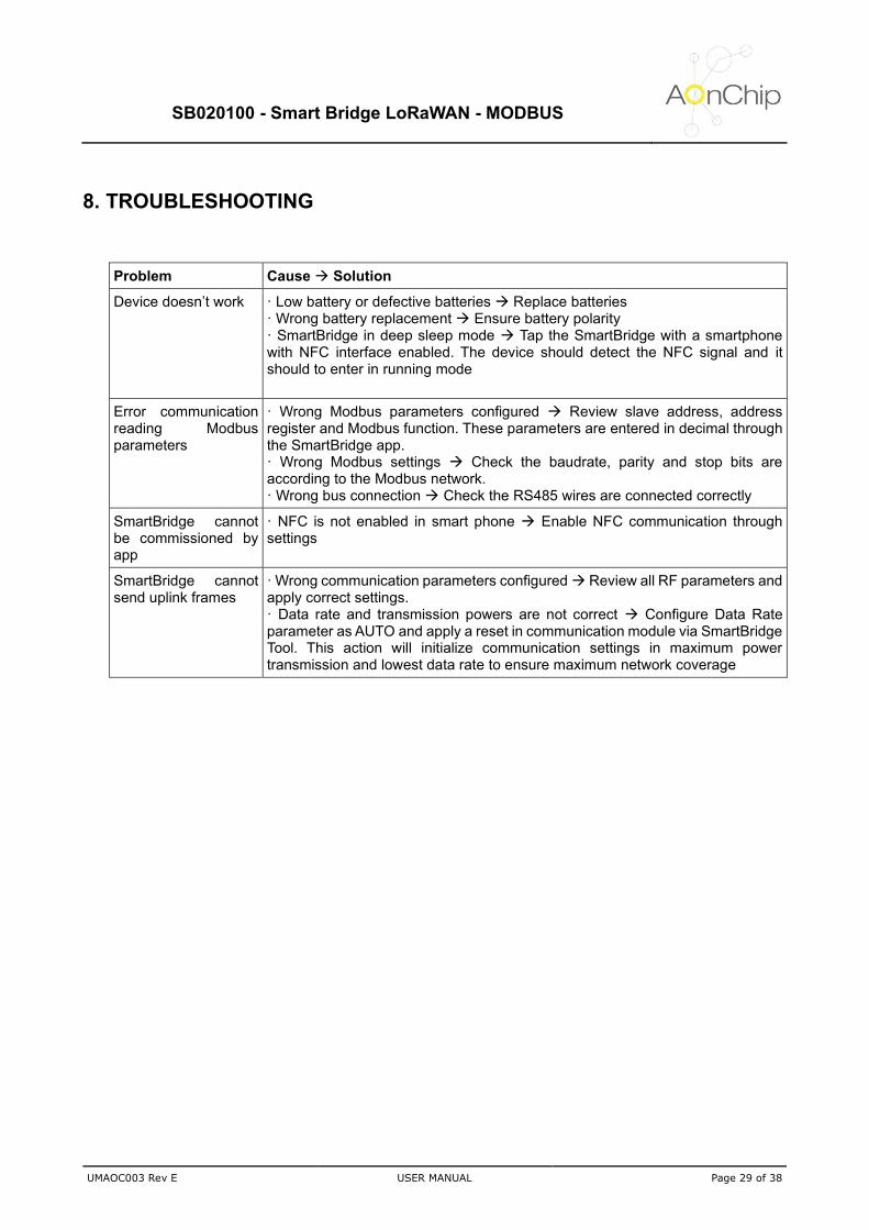
8. TROUBLESHOOTING
Problem Cause → Solution
Device doesn’t work · Low battery or defective batteries → Replace batteries · Wrong battery replacement → Ensure battery polarity · SmartBridge in deep sleep mode → Tap the SmartBridge with a smartphone with NFC interface enabled. The device should detect the NFC signal and it should to enter in running mode
Error communication reading Modbus parameters
· Wrong Modbus parameters configured → Review slave address, address register and Modbus function. These parameters are entered in decimal through the SmartBridge app. · Wrong Modbus settings → Check the baudrate, parity and stop bits are according to the Modbus network. · Wrong bus connection → Check the RS485 wires are connected correctly
SmartBridge cannot be commissioned by app
· NFC is not enabled in smart phone → Enable NFC communication through settings
SmartBridge cannot send uplink frames
· Wrong communication parameters configured → Review all RF parameters and apply correct settings. · Data rate and transmission powers are not correct → Configure Data Rate parameter as AUTO and apply a reset in communication module via SmartBridge Tool. This action will initialize communication settings in maximum power transmission and lowest data rate to ensure maximum network coverage

SB020100 - Smart Bridge LoRaWAN - MODBUS
UMAOC003 Rev E USER MANUAL Page 30 of 38
9. MAINTENANCE AND TECHNICAL SERVICE If the device is going to be switched off for a long time it is recommended to send “Reset Communications” command through Android application tool. If the SmartBridge is not able to join with any LoRaWAN network then after five attempts of joining the device will be enter in deep sleep mode. In case of battery replacement, replace them by batteries with same features (voltage, capacity, maximum output current, etc)
9.1. Battery replacement procedure
1. Disconnect SmartBridge from external Modbus network 2. Remove screws from housing 3. Remove housing from the cover. Be careful with internal antenna cable and wire connectors 4. Remove old batteries from holders and put new batteries 5. Press reset button to reset the system (this step is very important to avoid reset all system to work properly) 6. Make all connections and ensure all well done. 7. Ensure the O-ring is placed correctly to avoid humidity inside the housing in wet environments. 8. Fit the housing and the cover and screw them 9. Date and time were lost. Configure time and date through downlink frame time and date setup or via NFC with SmartBridge app (select synchronize date-time)
9.2. Firmware update
Watersens can be updated with last firmware version to get new features or to solve any deviation detected in previous versions. For this purpose, it is necessary:
• Last firmware Watersens version can be downloaded from web www.aonchip.com
• Software to download firmware to Watersens: https://www.st.com/content/st_com/en/products/development-tools/software-development-tools/stm32-software-development-tools/stm32-programmers/flasher-stm32.html
• USB to TTL cable FTDI TTL-232R-3V3 or similar: https://www.ftdichip.com/Support/Documents/DataSheets/Cables/DS_TTL-232R_CABLES.pdf
Procedure for firmware update:

SB020100 - Smart Bridge LoRaWAN - MODBUS
UMAOC003 Rev E USER MANUAL Page 31 of 38
1. Disconnect SmartBridge from external sensors 2. Remove screws from housing 3. Remove housing from the cover. Be careful with internal antenna cable and wire connectors 4. Connect communication cable to programming connector and press the reset button. GND pin cable must be connected in pin 1 of the circuit connector
Figure 13. Programming connector and reset button locations
5. Launch the PC software and follow indications.
Figure 14. Screenshot of the PC software for Watersens updating
6. Once the SmartBridge is updated, press reset button to start normal operation. 7. Ensure the O-ring is placed correctly to avoid humidity inside the housing in wet environments. 8. Fit the housing and the cover and screw them 9. Perform a reset communication through Android app via NFC connectivity
SB020100 - Smart Bridge LoRaWAN - MODBUS
UMAOC003 Rev E USER MANUAL Page 32 of 38
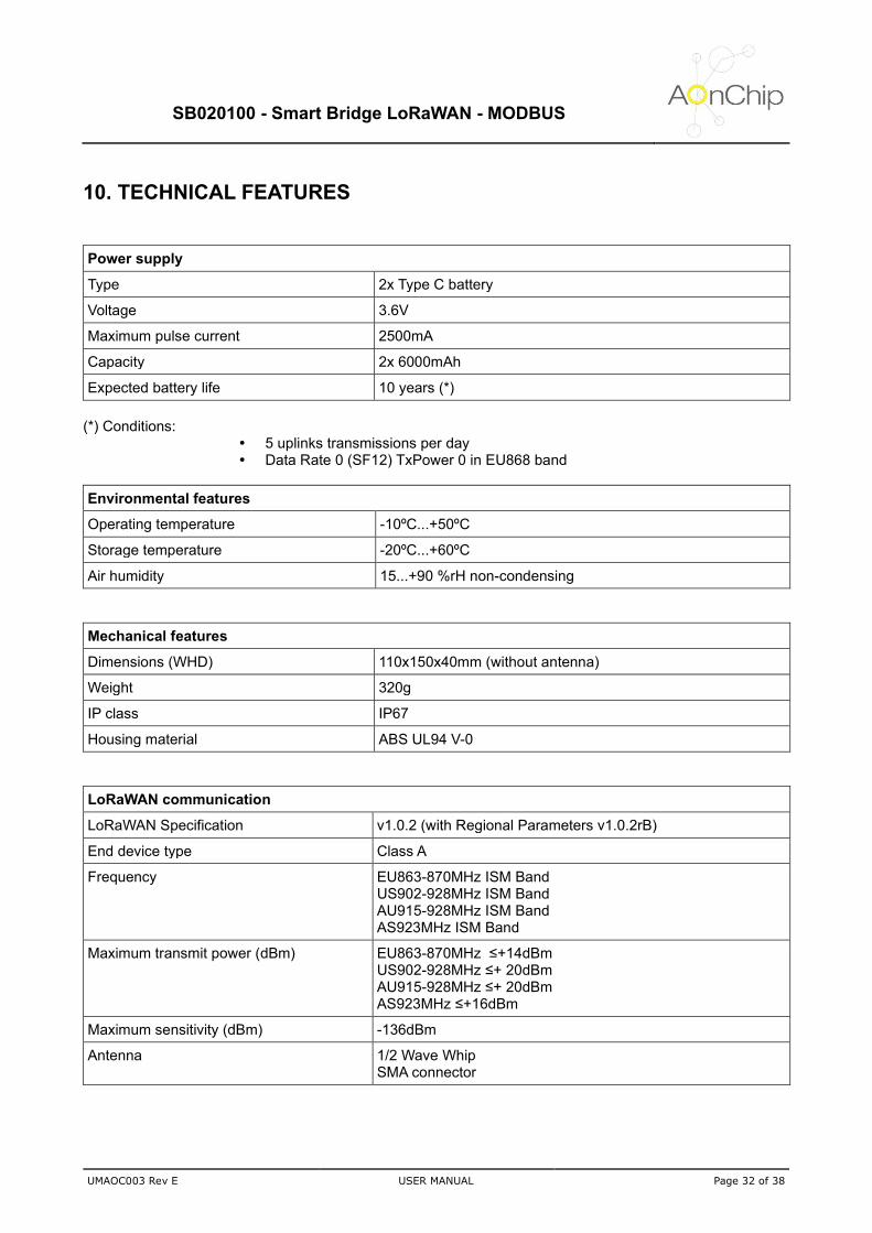
10. TECHNICAL FEATURES
Power supply
Type 2x Type C battery
Voltage 3.6V
Maximum pulse current 2500mA
Capacity 2x 6000mAh
Expected battery life 10 years (*)
(*) Conditions:
5 uplinks transmissions per day Data Rate 0 (SF12) TxPower 0 in EU868 band
Environmental features
Operating temperature -10ºC...+50ºC
Storage temperature -20ºC...+60ºC
Air humidity 15...+90 %rH non-condensing
Mechanical features
Dimensions (WHD) 110x150x40mm (without antenna)
Weight 320g
IP class IP67
Housing material ABS UL94 V-0
LoRaWAN communication
LoRaWAN Specification v1.0.2 (with Regional Parameters v1.0.2rB)
End device type Class A
Frequency EU863-870MHz ISM Band US902-928MHz ISM Band AU915-928MHz ISM Band AS923MHz ISM Band
Maximum transmit power (dBm) EU863-870MHz ≤+14dBm US902-928MHz ≤+ 20dBm AU915-928MHz ≤+ 20dBm AS923MHz ≤+16dBm
Maximum sensitivity (dBm) -136dBm
Antenna 1/2 Wave Whip SMA connector

SB020100 - Smart Bridge LoRaWAN - MODBUS
UMAOC003 Rev E USER MANUAL Page 33 of 38
NFC communication
Frequency 13.56MHz
Interface Passive NFC
Memory access Read - allowed Write - allowed
Internal sensor
Housing temperature Range: -20ºC...+60ºC Resolution: 0.5ºC
Modbus communication
Type Modbus RTU
Physical link RS485 2 wires (A - B) and shield connection optional
Baudrate programmable 1200, 2400, 4800, 9600, 19200, 38400, 57600, 115200
Data bit length 8
Stop bits 1 or 2
Parity None, Even, Odd
SB020100 - Smart Bridge LoRaWAN - MODBUS
UMAOC003 Rev E USER MANUAL Page 34 of 38
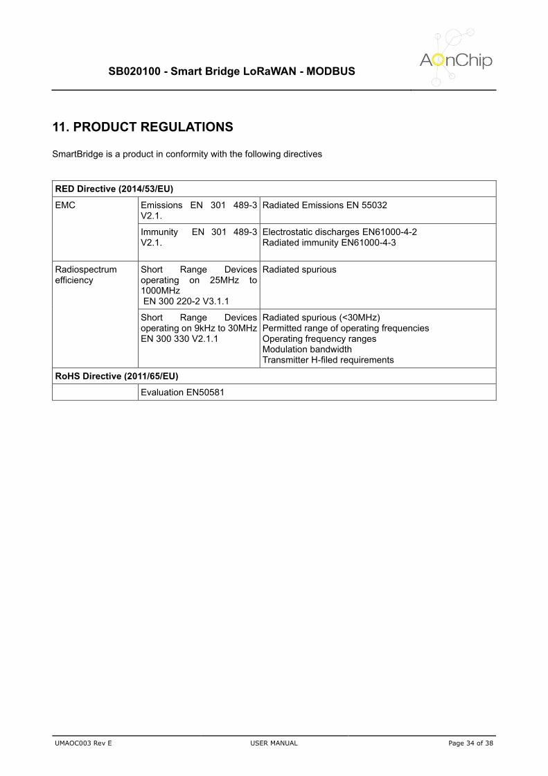
11. PRODUCT REGULATIONS SmartBridge is a product in conformity with the following directives
RED Directive (2014/53/EU)
EMC Emissions EN 301 489-3 V2.1.
Radiated Emissions EN 55032
Immunity EN 301 489-3 V2.1.
Electrostatic discharges EN61000-4-2 Radiated immunity EN61000-4-3
Radiospectrum efficiency
Short Range Devices operating on 25MHz to 1000MHz EN 300 220-2 V3.1.1
Radiated spurious
Short Range Devices operating on 9kHz to 30MHz EN 300 330 V2.1.1
Radiated spurious (<30MHz) Permitted range of operating frequencies Operating frequency ranges Modulation bandwidth Transmitter H-filed requirements
RoHS Directive (2011/65/EU)
Evaluation EN50581

SB020100 - Smart Bridge LoRaWAN - MODBUS
UMAOC003 Rev E USER MANUAL Page 35 of 38
12. TRADEMARKS All referenced brands, product names, services names and trademarks are the property of their respective owners.

SB020100 - Smart Bridge LoRaWAN - MODBUS
UMAOC003 Rev E USER MANUAL Page 36 of 38
13. GUARANTEE AONCHIP guarantees its products against any manufacturing defect for two years after the delivery of the units.
AONCHIP will repair or replace any defective factory product returned during the guarantee period. Pay attention
• No returns will be accepted and no unit will be repaired or replaced if it is not attached a report indicating the defect detected or the reason for the return. •The guarantee will be void if the units have been improperly used or the storage, installation and maintenance instructions listed in this manual have not been followed. “Improper usage” is defined as any operating or storage condition not allowed in the national electrical code or that overcomes the limits indicated in the technical and environmental features of this manual. • AONCHIP accepts no liability due to the possible damage to the unit or other parts of the installation, nor will it cover any possible sanctions derived from a possible failure, improper installation or “improper usage” of the unit. Consequently, this guarantee does not apply to failures as: - Excessive temperatures; - Improper installation and/or lack of maintenance; - Buyer repairs or modifications without the manufacturer’s authorization.

SB020100 - Smart Bridge LoRaWAN - MODBUS
UMAOC003 Rev E USER MANUAL Page 37 of 38
14. DOCUMENT HISTORY
Rev. Date Changes
A 05-Aug-2019 First edition
B 08-Aug-2019 Included new functionality to get float values from the Modbus slaves
C 21-Jul-2020 Included new functionality. Modbus registers management up to 20 registers
D 24-Feb-2021 Errata corrections
E 02-March-2021 User manual adapted to new hardware version. Included firmware update procedure

SB020100 - Smart Bridge LoRaWAN - MODBUS
UMAOC003 Rev E USER MANUAL Page 38 of 38
15. CONTACT INFORMATION
For more information, please visit: http://www.aonchip.com For sales please send an email to: [email protected]
IOT AONCHIP S.L. CEMENTIRI VELL, 12 1 - 1, 08221 TERRASSA – BARCELONA, SPAIN web. www.aonchip.com,