Smart Utility Meter CEDAR-20 1
11
SMART UTILITY METER CEDAR-20
Transcript of Smart Utility Meter CEDAR-20 1

SMART UTILITY METERCEDAR-20
INTRODUCTION
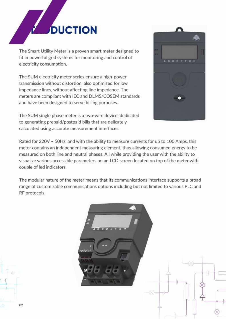
The Smart Utility Meter is a proven smart meter designed to fit in powerful grid systems for monitoring and control of electricity consumption.
The SUM electricity meter series ensure a high-power transmission without distortion, also optimized for low impedance lines, without affecting line impedance. The meters are compliant with IEC and DLMS/COSEM standards and have been designed to serve billing purposes.
The SUM single phase meter is a two-wire device, dedicated to generating prepaid/postpaid bills that are delicately calculated using accurate measurement interfaces.
Rated for 220V – 50Hz, and with the ability to measure currents for up to 100 Amps, this meter contains an independent measuring element, thus allowing consumed energy to be measured on both line and neutral phases. All while providing the user with the ability to visualize various accessible parameters on an LCD screen located on top of the meter with couple of led indicators.
The modular nature of the meter means that its communications interface supports a broad range of customizable communications options including but not limited to various PLC and RF protocols.
02
03
FLEXIBILITY
• PRIME Communication Interface• Compliant with IEC and DLMS/COSEM• Modular Communication interface• Programmable relay (Line and Neutral Control)• Zero crossing switching• 1 RS485 interface (HDLC)• Optical Interface (HDLC Mode E)• Remote Firmware upgrade• Alarms and events logs• Covers opening detection• Security attacks detection• Current Bypass Connection• Auto-diagnostics• Instantaneous measurements• Quadrants : Q1 / Q2 / Q3 / Q4, Import/Export (net metering)• Current measurement for line and neutral
• NON-Technical Losses detection by comparing line and neutral currents• In house software and hardware design expedite change request and feature additions• Modular communication interface helps overcome connectivity issues• Modular power supply provides ability of voltage input range change if desired• General purpose auxiliary interface (1 input, 2 outputs) to synchronize with external event
KEY FEATURES
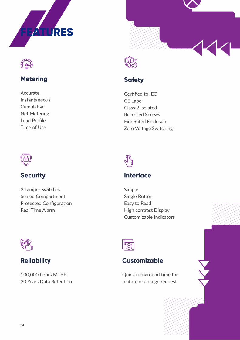
Metering
AccurateInstantaneousCumulativeNet MeteringLoad ProfileTime of Use
Safety
Certified to IECCE LabelClass 2 IsolatedRecessed ScrewsFire Rated EnclosureZero Voltage Switching
Security
2 Tamper SwitchesSealed CompartmentProtected ConfigurationReal Time Alarm
Interface
SimpleSingle ButtonEasy to ReadHigh contrast DisplayCustomizable Indicators
Reliability
100,000 hours MTBF20 Years Data Retention
Customizable
Quick turnaround time for feature or change request
04
FEATURES

VoltageNominal Voltage: 160V to 265V phase-to-neutral
Current (amperage depends on local regulatory requirements)
• Basic: 5A• Maximum: 100A
Service and Connection Types• Single phase two wire service• Direct line/load connections
Power ConsumptionApparent Power: <10VA
FrequencyNominal Frequency: 50 Hz ±5%
Temperature and Humidity• Specified Operating Range: -40° to +70° C
(3K7). Display fully operational from-25° to +60° C. Humidity: <=95% RH, non-condensing
• Storage and Transport: -40° to +85° C. Humidity: <=85% RH, non-condensing.Must remain sealed within the desiccant bags in which they are shipped tomeet storage and transport ratings.
05
SPECIFICATION

Installation• Mounting: DIN 43857• Enclosure: Outdoor (IP54)• Class 2 isolated auxiliary wiring terminals: Wire size 0.4mm-1.3mm diameter• Power and load wires: up to 50mm2
Certifications• Measurement Accuracy Compliance
Active Energy:- IEC 62053-21 Class 1 Reactive Energy:- IEC 62053-23 Class 2
• Environment: IEC 62052-11• Tariff and Load Control: IEC 62054-21• Safety Ratings: IEC 61010-1 CE marked.• Timing/Real Time Clock: Accurate per IEC 62052-21 [2004] and IEC• Communication:
CENELEC A EN50065 PRIME Optical Port IEC 62056-21
• Data: DLMS/COSEM
Communications• PRIME 1.3.6, CENELEC A-band power line communication channel• Optical Port IEC 62056-21• Isolated current loop with external RS485 adapter• DLMS Security Suites 0 and 1
Load Disconnect• UC3 compliant up to 100A• Mechanical Endurance: 100,000 cycles• Electrical Endurance: 10,000 cycles• Maximum Overload Current: 120A, 150A (30 minutes)• Maximum Switching Voltage: 265VAC• Maximum Switching Power: 30,000VA
06
SPECIFICATION

07
2
5
4
1
3
6
7
8
10
9
1. LCD Screen2. LED Indicators3. Programming Button4. Auxiliary Connectors5. Terminal Block
6. Serial Connector7. Tamper Switch8. Optical Port9. Customizable Indicators10. User Button
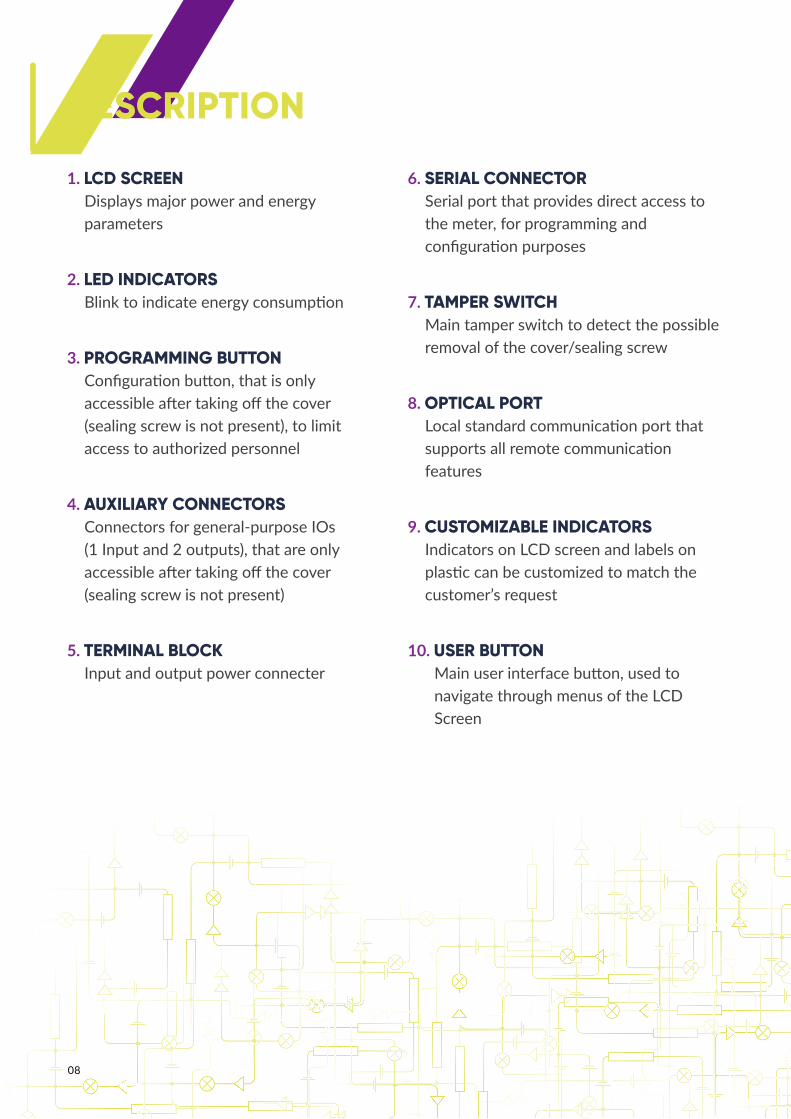
DESCRIPTION
DESCRIPTION
08
1. LCD SCREENDisplays major power and energy parameters
2. LED INDICATORS Blink to indicate energy consumption
3. PROGRAMMING BUTTONConfiguration button, that is only accessible after taking off the cover (sealing screw is not present), to limit access to authorized personnel
4. AUXILIARY CONNECTORSConnectors for general-purpose IOs (1 Input and 2 outputs), that are only accessible after taking off the cover (sealing screw is not present)
5. TERMINAL BLOCK Input and output power connecter
6. SERIAL CONNECTORSerial port that provides direct access to the meter, for programming and configuration purposes
7. TAMPER SWITCHMain tamper switch to detect the possible removal of the cover/sealing screw
8. OPTICAL PORTLocal standard communication port that supports all remote communication features
9. CUSTOMIZABLE INDICATORSIndicators on LCD screen and labels on plastic can be customized to match the customer’s request
10. USER BUTTONMain user interface button, used to navigate through menus of the LCD Screen
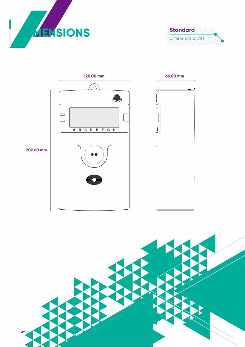
DIMENSIONS
09
202.60 mm
120.00 mm 66.00 mm
StandardDimensions to DIN
10
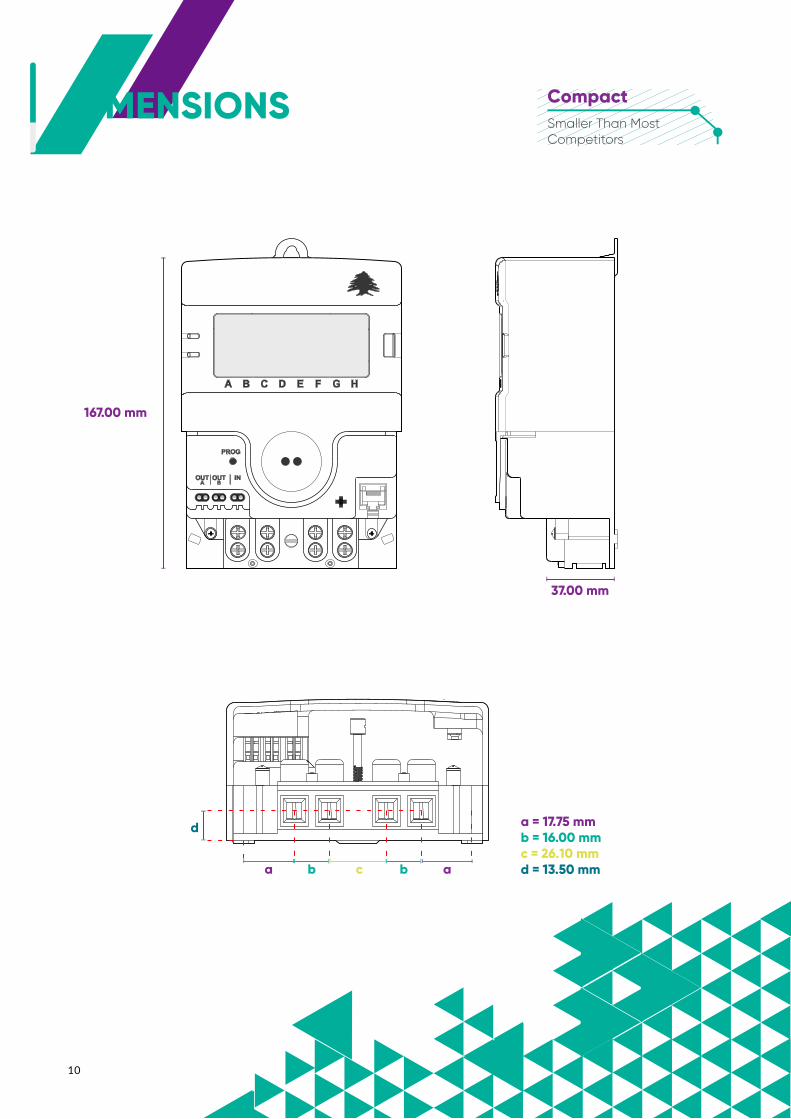
DIMENSIONS
167.00 mm
37.00 mm
a b
d
c b a
a = 17.75 mmb = 16.00 mmc = 26.10 mmd = 13.50 mm
CompactSmaller Than Most Competitors

Copyright © 2020 CME. All rights reserved. gotocme.com
DIMENSIONS LEBANESEWith GreetingsCompletely Designed &Made in Lebanon
Disclaimer Notice:All features, functionality and other product specifications are subject to change without notice or obligation.
155.00 mm
105.00 mm