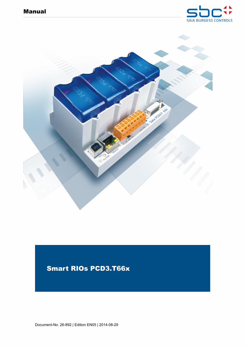
Smart RIOs PCD3 - Authorized SAIA PLC Distributor T66x 26-892.pdf · Saia-uress Controls A Manual...
33
Document-No. 26-892 | Edition EN05 | 2014-08-29 Manual Smart RIOs PCD3.T66x
Transcript of Smart RIOs PCD3 - Authorized SAIA PLC Distributor T66x 26-892.pdf · Saia-uress Controls A Manual...
Document-No. 26-892 | Edition EN05 | 2014-08-29
Manual
Smart RIOs PCD3.T66x

Saia-Burgess Controls AG
Manual Smart RIOs PCD3.T66x│Document 26/892; Edition EN05│2014-08-29
Content
0-1
00 Content0 Content
0.1 Document-History ............................................................................................... 0-20.2 Trademarks ......................................................................................................... 0-2
1 Introduction 1.1 System overview ............................................................................................... 1-11.2 System requirements ......................................................................................... 1-21.3 Steps to configure, program and commission
a Distributed Automation Network (DAN) ........................................................... 1-3
2 How to create a Distributed Automation Network (DAN) 2.1 Create a Smart RIO Network ............................................................................. 2-1
3 ConfigurationandBuildofSmartRIOstations withoutprogram
3.1 Configuration in the Device Configurator ............................................................ 3-13.2 Media Mapping in the RIO Network Configurator ............................................... 3-33.3 Build and Download of the Smart RIO project .................................................... 3-5
4 ConfigurationandBuildofSmartRIOsstation withaprogram
4.1 Configuration in the Device Configurator ............................................................ 4-24.2 Media Mapping in the RIO Network Configurator ............................................... 4-44.3 Creating user programs for Smart RIOs ............................................................. 4-74.4 Build and Download of Smart RIO project with user program ............................ 4-84.5 Online functions and program debugging ........................................................... 4-104.6 Using the RIO’s built-in Web-Server ................................................................... 4-11
5 ConfigurationofIPsettingsinaRIOstation
6 Troubleshootinganddiagnostics6.1 Diagnostic Flags ................................................................................................. 6-16.2 Built-in web page ................................................................................................ 6-26.3 LED display ........................................................................................................ 6-3
A AppendixA.1 Icons ................................................................................................................... A-1A.2 Technical Data .................................................................................................... A-2A.3 Address of Saia-Burgess Controls AG .............................................................. A-3
Saia-Burgess Controls AG
Manual Smart RIOs PCD3.T66x│Document 26/892; Edition EN05│2014-08-29
Document-History | Trademarks
Content
0-2
00.1 Document-History
Version Published Changed Remarks
pEN01 2010-11-05 - Initial edition
pEN01 2011-05-04 - Version in InDesign
EN01 2011-06-14 - PCD3.T660 removedEN01 2011-07-20 - publishedEN02 2011-08-23 2011-08-23 Chapter 1.2 “System requirements”: Adaption of the
FW versionsEN03 2013-03-18 2013-03-18 Chapter 3.1 Download of the configuration with the
Device Configurator is possible
EN04 2014-01-23 2014-01-23 Change of logoEN05 2014-08-29 2014-08-29 General data added
0.2 Trademarks
Saia PCD® is a registered trademark of Saia-Burgess Controls AG.
Technical changes are subject to the state of technology
Saia-Burgess Controls AG, 2014. © All rights reserved.
Published in Switzerland
Saia-Burgess Controls AG
Manual Smart RIOs PCD3.T66x│Document 26/892; Edition EN05│2014-08-29
System overview
Introduction
1-1
1
1 Introduction
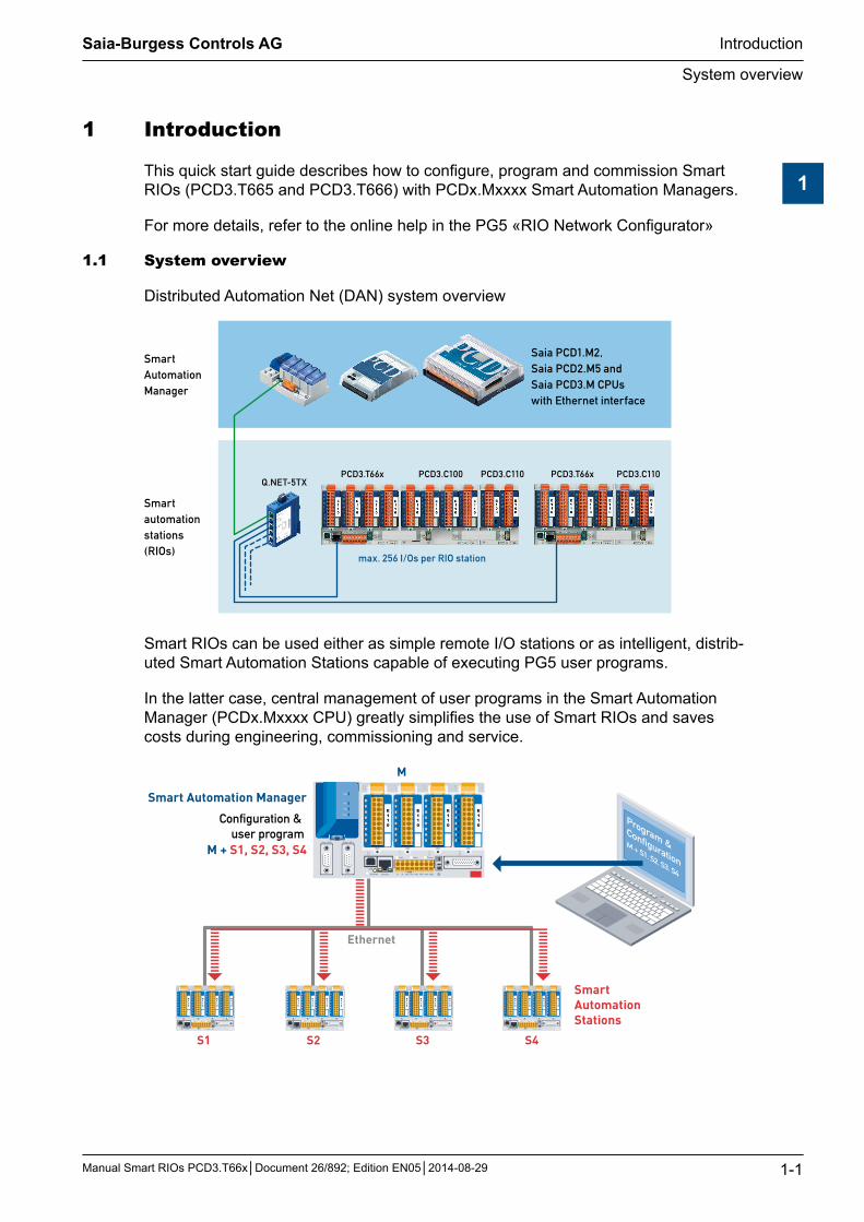
This quick start guide describes how to configure, program and commission Smart RIOs (PCD3.T665 and PCD3.T666) with PCDx.Mxxxx Smart Automation Managers.
For more details, refer to the online help in the PG5 «RIO Network Configurator»
1.1 System overview
Distributed Automation Net (DAN) system overview
PCD3.T66xQ.NET-5TX
PCD3.C100 PCD3.C110 PCD3.T66x PCD3.C110
Ethernet
Smart Automation Manager
Smart automation stations (RIOs)
Saia PCD1.M2, Saia PCD2.M5 and Saia PCD3.M CPUs with Ethernet interface
max. 256 I/Os per RIO station
Smart RIOs can be used either as simple remote I/O stations or as intelligent, distrib-uted Smart Automation Stations capable of executing PG5 user programs.
In the latter case, central management of user programs in the Smart Automation Manager (PCDx.Mxxxx CPU) greatly simplifies the use of Smart RIOs and saves costs during engineering, commissioning and service.
M + S1, S2, S3, S4
M
Ethernet
S1 S2 S3 S4
Program & Configuration
M + S1, S2, S3, S4
Configuration & user program
Smart Automation Manager
Smart Automation Stations
E110
E110
E110
E110
E110
E110
E110
E110
E110
E110
E110
E110
E110
E110
E110
E110
E110
E110
E110
E110
Saia-Burgess Controls AG
Manual Smart RIOs PCD3.T66x│Document 26/892; Edition EN05│2014-08-29
System overview | System requirements
Introduction
1-2
1
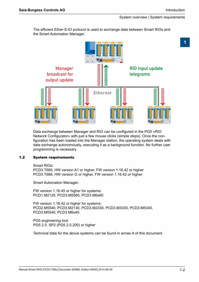
The efficient Ether-S-IO protocol is used to exchange data between Smart RIOs and the Smart Automation Manager.
Managerbroadcast foroutput update
RIO input updatetelegrams
Ethernet
E110
E110
E110
E110
E110
E110
E110
E110
E110
E110
E110
E110
E110
E110
E110
E110
E110
E110
E110
E110
Data exchange between Manager and RIO can be configured in the PG5 «RIO Network Configurator» with just a few mouse clicks (simple steps). Once the con-figuration has been loaded into the Manager station, the operating system deals with data exchange autonomously, executing it as a background function. No further user programming is necessary.
1.2 System requirements
Smart RIOs: PCD3.T665, HW version A1 or higher, FW version 1.16.42 or higher PCD3.T666, HW version G or higher, FW version 1.16.42 or higher
Smart Automation Manager:
FW version 1.16.45 or higher for systems: PCD1.M2120, PCD3.M5560, PCD3.M6x60
FW version 1.16.42 or higher for systems: PCD2.M5540, PCD3.M2130, PCD3.M2330, PCD3.M3330, PCD3.M5340, PCD3.M5540, PCD3.M6x40.
PG5 engineering tool: PG5 2.0. SP2 (PG5 2.0.200) or higher
Technical data for the above systems can be found in annex A of this document.

Saia-Burgess Controls AG
Manual Smart RIOs PCD3.T66x│Document 26/892; Edition EN05│2014-08-29
Steps to configure, program and commission a (DAN)
Introduction
1-3
1
1.3 Stepstoconfigure,programandcommission a Distributed Automation Network (DAN)
The following is a brief list of the necessary steps. For details, refer to subsequent chapters.
1. Create a new project in PG5 2.0 Project Manager
2. Create a CPU which will be used as Smart Automation Manager
3. Activate and configure the Ethernet interface of the Manager in the Device Con-figurator
a) Activate an Ethernet RIO network4. Add RIO stations in the Project Manager
5. Configure RIO stations (I/O modules, media mapping, IP address, etc.) in the De-vice Configurator
6. Configure data exchange and any media mapping between Manager and RIO in the RIO Network Configurator
7. Create the user program for the Manager and the RIOs (if required)
8. Build and download the program in the Smart Automation Manager
9. Before the RIO station can be used, configure the IP settings with the help of the built-in Configuration web page. This can be accessed using a PC browser via USB (in this case Web-Connect is required) or Ethernet interface (default IP ad-dress: 192.168.10.100)
Saia-Burgess Controls AG
Manual Smart RIOs PCD3.T66x│Document 26/892; Edition EN05│2014-08-29
Create a Smart RIO Network
How to create a Distributed Automation Network (DAN)
2-1
2
2 How to create a Distributed Automation Network (DAN)
2.1 Create a Smart RIO Network
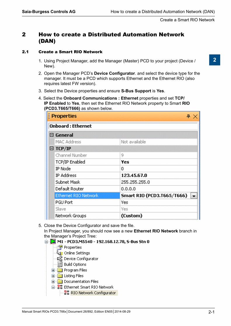
1. Using Project Manager, add the Manager (Master) PCD to your project (Device / New).
2. Open the Manager PCD’s Device Configurator. and select the device type for the manager. It must be a PCD which supports Ethernet and the Ethernet RIO (also requires latest FW version).
3. Select the Device properties and ensure S-Bus Support is Yes.
4. Select the Onboard Communications : Ethernet properties and set TCP/IP Enabled to Yes, then set the Ethernet RIO Network property to Smart RIO (PCD3.T665/T666) as shown below.
5. Close the Device Configurator and save the file. In Project Manager, you should now see a new Ethernet RIO Network branch in the Manager’s Project Tree:

Saia-Burgess Controls AG
Manual Smart RIOs PCD3.T66x│Document 26/892; Edition EN05│2014-08-29
Create a Smart RIO Network
How to create a Distributed Automation Network (DAN)
2-2
2
6. Now you can start adding RIOs to your network
RIOs can be created from Project Manager: Right-click on the Ethernet RIO’s branch in the Project Tree and select New RIO...
Each RIO must have a unique name, i.e. it cannot have the same name as any other device in the project. (Copy/Paste of an existing RIO is also supported.)
The above screen can be used to set a RIO’s IP address. If the RIO has a program, the check box “Has Program” must be selected. Chapter 4 explains how to use RIOs that have a program.
Close the window by pressing the OK button.

Saia-Burgess Controls AG
Manual Smart RIOs PCD3.T66x│Document 26/892; Edition EN05│2014-08-29
Create a Smart RIO Network
How to create a Distributed Automation Network (DAN)
2-3
2
The RIO that has just been added should now appear as follows in the RIO Network Configurator and the Project Manager.
RIO Network Configurator:
Project Manager:
Saia-Burgess Controls AG
Manual Smart RIOs PCD3.T66x│Document 26/892; Edition EN05│2014-08-29
Configuration in the Device Configurator
Configuration and Build without program
3-1
3
3 ConfigurationandBuildofSmartRIOstations withoutprogram
3.1 ConfigurationintheDeviceConfigurator
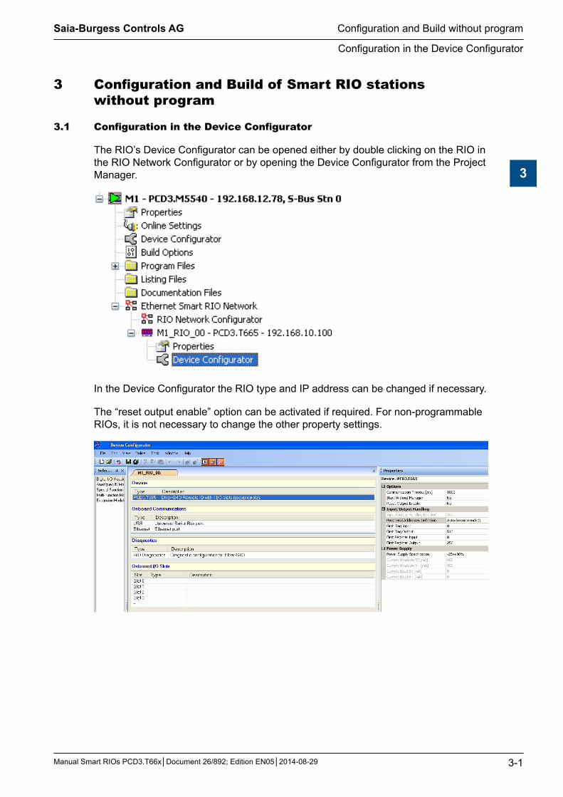
The RIO’s Device Configurator can be opened either by double clicking on the RIO in the RIO Network Configurator or by opening the Device Configurator from the Project Manager.
In the Device Configurator the RIO type and IP address can be changed if necessary.
The “reset output enable” option can be activated if required. For non-programmable RIOs, it is not necessary to change the other property settings.

Saia-Burgess Controls AG
Manual Smart RIOs PCD3.T66x│Document 26/892; Edition EN05│2014-08-29
Configuration in the Device Configurator
Configuration and Build without program
3-2
3
Configuring the RIO’s I/O modules
I/O modules are now added from the module selector:
Ensure Media Mapping is enabled. It is not necessary to modify addresses or symbol definitions for RIOs that have no program.
The inputs/outputs of analogue modules and other special modules should be config-ured in the same way as for a standard PCD.
The RIO configuration can be downloaded from the Device Configurator into the Smart RIO station (Must never be downloaded with Firmware version < FW 1.16.xx).The I/O configuration is downloaded with the user program in the Manager Station. The Manager automatically sends the configuration to the RIOs after startup. For details refer to chapter 3.3. A RIO’s IP address can be set using the PC browser via a built-in web page in the RIO sta-tion. For details refer to chapter 5.
Saia-Burgess Controls AG
Manual Smart RIOs PCD3.T66x│Document 26/892; Edition EN05│2014-08-29
Media Mapping in the RIO Network Configurator
Configuration and Build without program
3-3
3
3.2 MediaMappingintheRIONetworkConfigurator
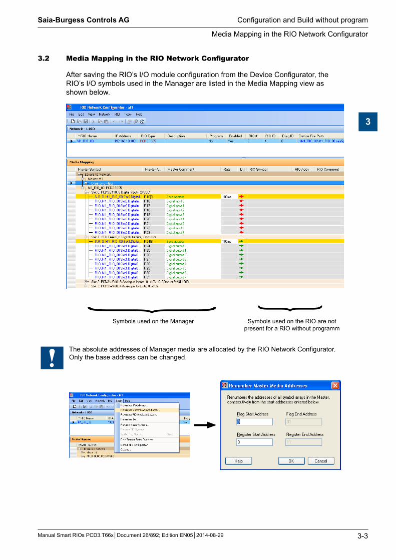
After saving the RIO’s I/O module configuration from the Device Configurator, the RIO’s I/O symbols used in the Manager are listed in the Media Mapping view as shown below.
{ {Symbols used on the Manager Symbols used on the RIO are not
present for a RIO without programm
The absolute addresses of Manager media are allocated by the RIO Network Configurator. Only the base address can be changed.
Saia-Burgess Controls AG
Manual Smart RIOs PCD3.T66x│Document 26/892; Edition EN05│2014-08-29
Media Mapping in the RIO Network Configurator
Configuration and Build without program
3-4
3
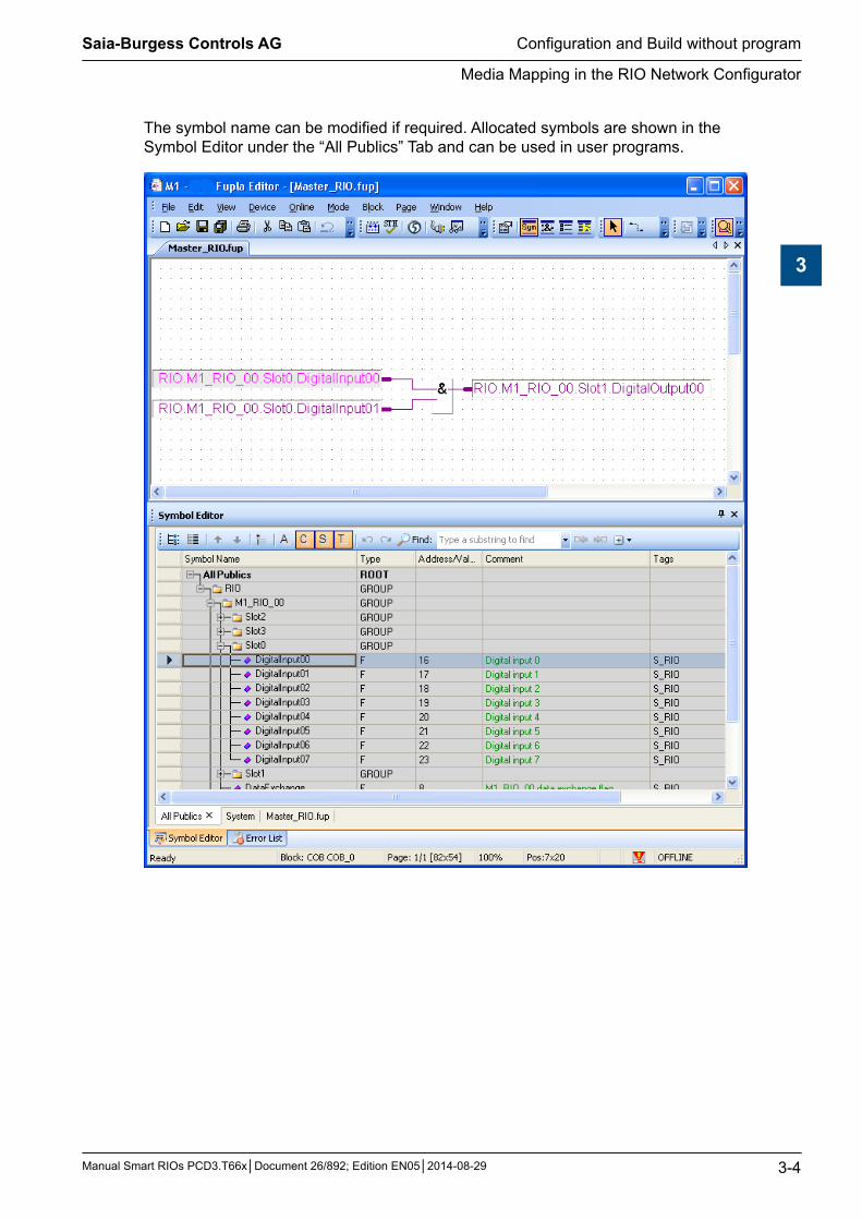
The symbol name can be modified if required. Allocated symbols are shown in the Symbol Editor under the “All Publics” Tab and can be used in user programs.
Saia-Burgess Controls AG
Manual Smart RIOs PCD3.T66x│Document 26/892; Edition EN05│2014-08-29
Build and Download of the Smart RIO project
Configuration and Build without program
3-5
3
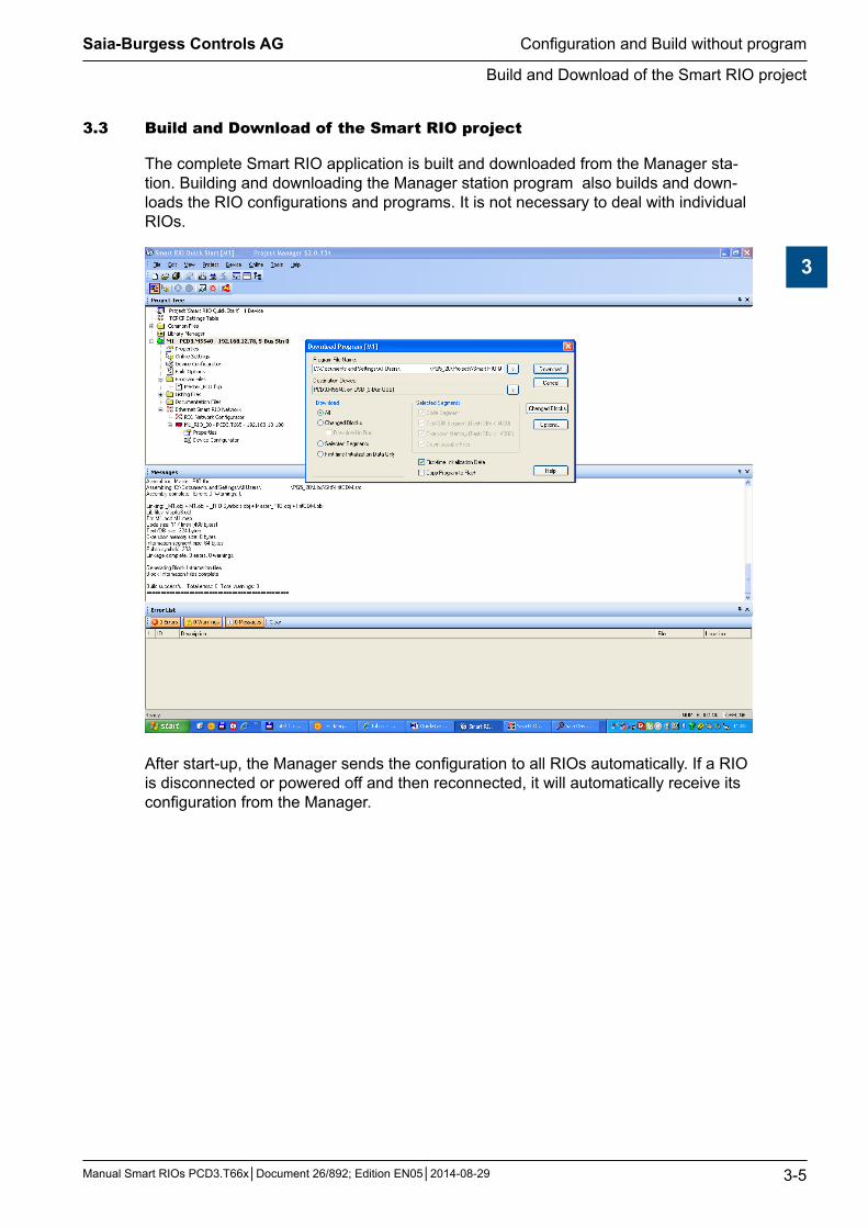
3.3 BuildandDownloadoftheSmartRIOproject
The complete Smart RIO application is built and downloaded from the Manager sta-tion. Building and downloading the Manager station program also builds and down-loads the RIO configurations and programs. It is not necessary to deal with individual RIOs.
After start-up, the Manager sends the configuration to all RIOs automatically. If a RIO is disconnected or powered off and then reconnected, it will automatically receive its configuration from the Manager.
Saia-Burgess Controls AG
Manual Smart RIOs PCD3.T66x│Document 26/892; Edition EN05│2014-08-29
Configuration and Build with a program
4-1
4
4 ConfigurationandBuildofSmartRIOsstation withaprogram
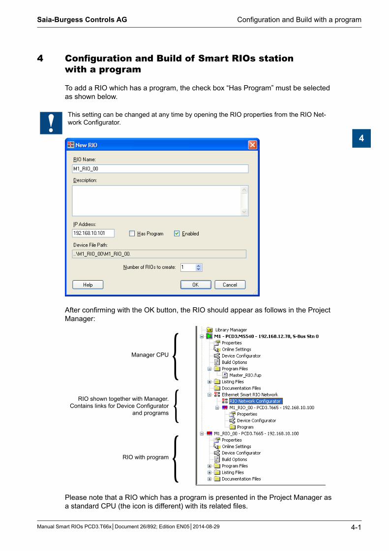
To add a RIO which has a program, the check box “Has Program” must be selected as shown below.
This setting can be changed at any time by opening the RIO properties from the RIO Net-work Configurator.
After confirming with the OK button, the RIO should appear as follows in the Project Manager:
Manager CPU {RIO shown together with Manager.
Contains links for Device Configurator and programs {
RIO with program {Please note that a RIO which has a program is presented in the Project Manager as a standard CPU (the icon is different) with its related files.

Saia-Burgess Controls AG
Manual Smart RIOs PCD3.T66x│Document 26/892; Edition EN05│2014-08-29
Configuration in the Device Configurator
Configuration and Build with a program
4-2
4
4.1 ConfigurationintheDeviceConfigurator
Presentation of RIO station which has a program in the Device Configurator:
In addition to the configuration for a RIO without program, the following settings can/should be modified if necessary.
Set the startup behaviour of the RIO when powering up without the Manager.
} The base addresses for I/O handling must be checked and set. Make sure there are no conflicts with the RIO user program
The base address of RIO diagnostic elements must also be checked and set.

Saia-Burgess Controls AG
Manual Smart RIOs PCD3.T66x│Document 26/892; Edition EN05│2014-08-29
Configuration in the Device Configurator
Configuration and Build with a program
4-3
4
Media Mapping and addresses for I/O modules.
Automatically generated symbol names for I/Os can be used or customized here.

Saia-Burgess Controls AG
Manual Smart RIOs PCD3.T66x│Document 26/892; Edition EN05│2014-08-29
Media Mapping in the RIO Network Configurator
Configuration and Build with a program
4-4
4
4.2 MediaMappingintheRIONetworkConfigurator
Presentation of a RIO with program:
Symbols used in the Manager
Transfer Cycle Time Transfer Direction
Symbols used in the RIO
{ {In addition to Manager symbols, those used in the RIO station are also listed.
All symbols listed will be exchanged between Manager and RIO. This means that, for example, if a RIO’s outputs are controlled by a user program in the RIO, they need to be disabled from data transfer. Otherwise, they will be overwritten by the Manager.
Cycle time can be set individually for every data transfer array. In this way, time-criti-cal signals (e.g. alarms) can be exchanged faster than non time-critical signals (e.g. temperature values).
Select appropriate cycle times. Do not set times that are unnecessarily short, since this will increase network traffic and add to the load on the Manager station. In the worst case, telegrams may even be lost. For more information refer to chapter 6. “Troubleshooting and Diagnostics”
2 different transfer cycle times can be set for each RIO station: – a short cycle time for high-priority data– normal cycle time for low-priority or slow data
Number of RIOs Minimum cycle timeData transfer
10 50 ms20 100 ms40 200 ms80 400 ms
128 800 ms
Data transfer cycle times
Saia-Burgess Controls AG
Manual Smart RIOs PCD3.T66x│Document 26/892; Edition EN05│2014-08-29
Media Mapping in the RIO Network Configurator
Configuration and Build with a program
4-5
4
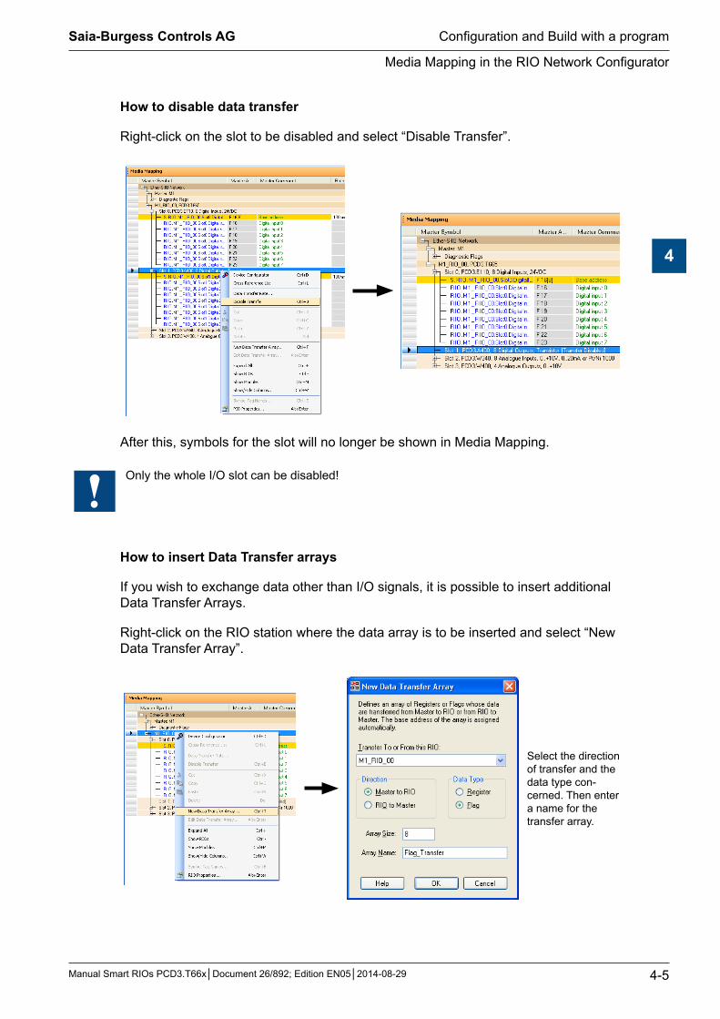
How to disable data transfer
Right-click on the slot to be disabled and select “Disable Transfer”.
After this, symbols for the slot will no longer be shown in Media Mapping.
Only the whole I/O slot can be disabled!
How to insert Data Transfer arrays
If you wish to exchange data other than I/O signals, it is possible to insert additional Data Transfer Arrays.
Right-click on the RIO station where the data array is to be inserted and select “New Data Transfer Array”.
Select the direction of transfer and the data type con-cerned. Then enter a name for the transfer array.
Saia-Burgess Controls AG
Manual Smart RIOs PCD3.T66x│Document 26/892; Edition EN05│2014-08-29
Media Mapping in the RIO Network Configurator
Configuration and Build with a program
4-6
4
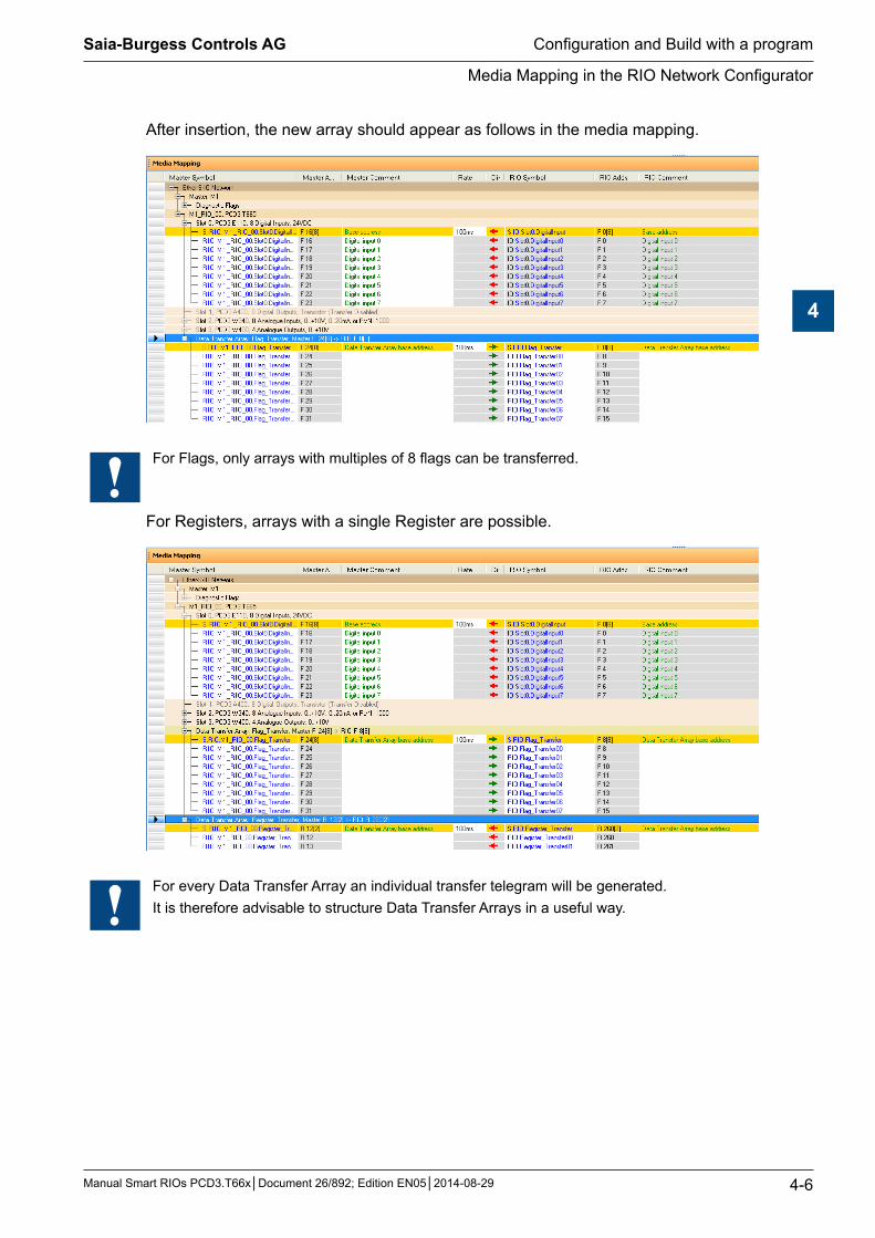
After insertion, the new array should appear as follows in the media mapping.
For Flags, only arrays with multiples of 8 flags can be transferred.
For Registers, arrays with a single Register are possible.
For every Data Transfer Array an individual transfer telegram will be generated. It is therefore advisable to structure Data Transfer Arrays in a useful way.
Saia-Burgess Controls AG
Manual Smart RIOs PCD3.T66x│Document 26/892; Edition EN05│2014-08-29
Creating user programs for Smart RIOs
Configuration and Build with a program
4-7
4
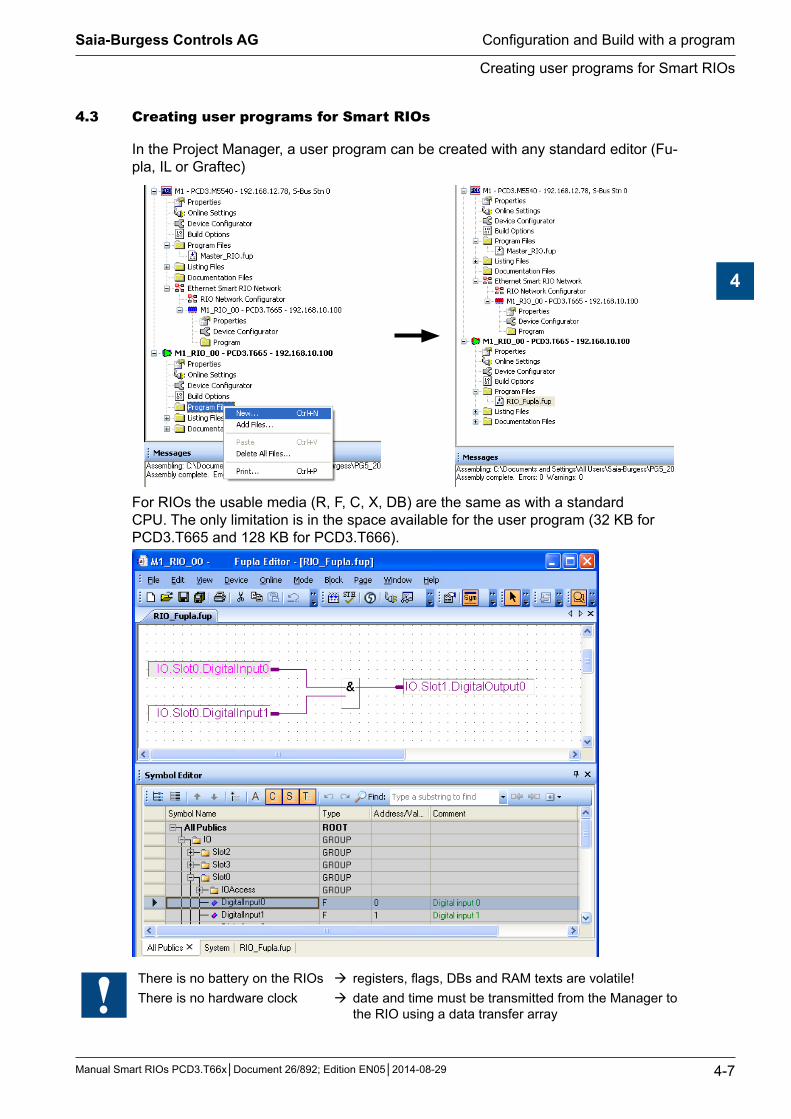
4.3 CreatinguserprogramsforSmartRIOs
In the Project Manager, a user program can be created with any standard editor (Fu-pla, IL or Graftec)
For RIOs the usable media (R, F, C, X, DB) are the same as with a standard CPU. The only limitation is in the space available for the user program (32 KB for PCD3.T665 and 128 KB for PCD3.T666).
There is no battery on the RIOs registers, flags, DBs and RAM texts are volatile!There is no hardware clock date and time must be transmitted from the Manager to
the RIO using a data transfer array

Saia-Burgess Controls AG
Manual Smart RIOs PCD3.T66x│Document 26/892; Edition EN05│2014-08-29
Build and Download of Smart RIO project with user program
Configuration and Build with a program
4-8
4
4.4 BuildandDownloadofSmartRIOprojectwithuserprogram
The complete Smart RIO application is built and downloaded from the Manager sta-tion. Building and downloading the Manager station program also builds and down-loads the RIO configurations and programs. It is not necessary to deal with individual RIOs.
For a quick check the RIO application can be built individually without the Manager project.
Select the RIO in the Project Manager:
The user program cannot (must not) be downloaded in the RIO station with the PG5 down-loader.

Saia-Burgess Controls AG
Manual Smart RIOs PCD3.T66x│Document 26/892; Edition EN05│2014-08-29
Build and Download of Smart RIO project with user program
Configuration and Build with a program
4-9
4
To build the complete Smart RIO Network project, the Manager station must be se-lected in the Project Manager and then the Build started.
If there are many RIO stations, a «Rebuild All Files» may take quite a long time.
To save time, «Build Changed Files» can be used. This will also include the RIO sta-tions.
The Smart RIO Network application is downloaded with the Manager’s user program.
After start-up, the Manager sends the configuration and user programs to all RIOs automatically. If a RIO is disconnected or powered off and then reconnected, it will automatically receive its configuration and program from the Manager.
Saia-Burgess Controls AG
Manual Smart RIOs PCD3.T66x│Document 26/892; Edition EN05│2014-08-29
Online functions and program debugging
Configuration and Build with a program
4-10
4
4.5 Onlinefunctionsandprogramdebugging
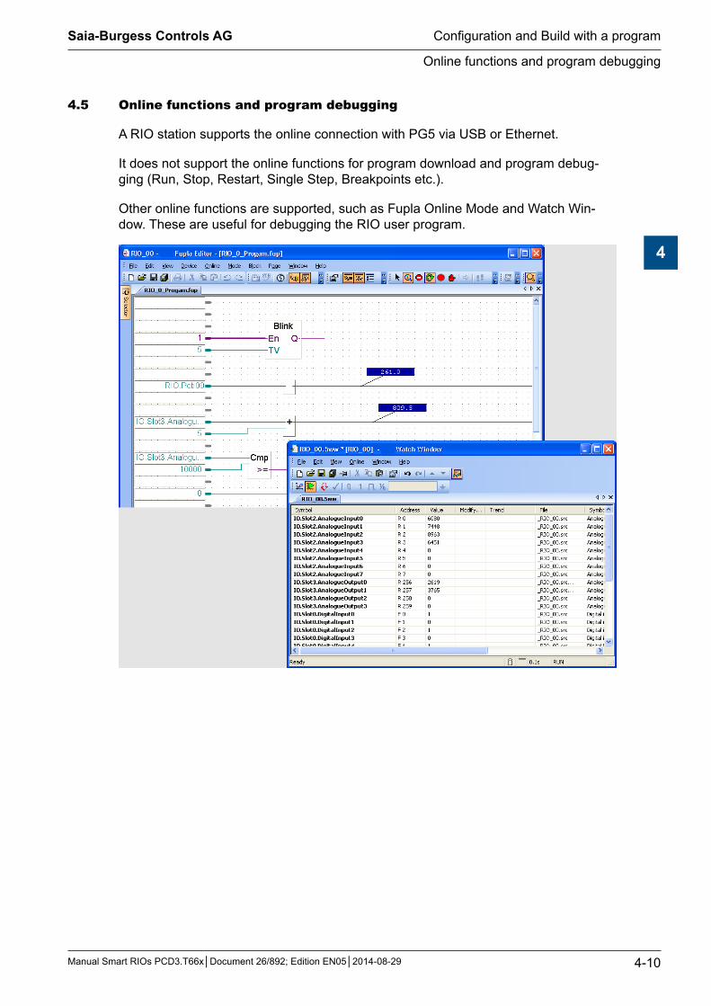
A RIO station supports the online connection with PG5 via USB or Ethernet.
It does not support the online functions for program download and program debug-ging (Run, Stop, Restart, Single Step, Breakpoints etc.).
Other online functions are supported, such as Fupla Online Mode and Watch Win-dow. These are useful for debugging the RIO user program.
Saia-Burgess Controls AG
Manual Smart RIOs PCD3.T66x│Document 26/892; Edition EN05│2014-08-29
Using the RIO’s built-in Web-Server
Configuration and Build with a program
4-11
4
4.6 UsingtheRIO’sbuilt-inWeb-Server
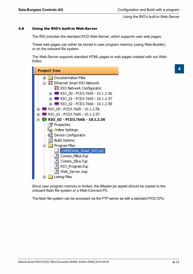
The RIO includes the standard PCD Web-Server, which supports user web pages.
These web pages can either be stored in user program memory (using Web-Builder) or on the onboard file system.
The Web-Server supports standard HTML pages or web pages created with our Web-Editor.
Since user program memory is limited, the IMaster.jar applet should be copied to the onboard flash file system or a Web-Connect PC.
The flash file system can be accessed via the FTP server as with a standard PCD CPU.
Saia-Burgess Controls AG
Manual Smart RIOs PCD3.T66x│Document 26/892; Edition EN05│2014-08-29
Configuration of IP settings in a RIO station
5-1
5
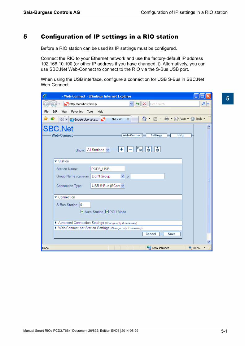
5 ConfigurationofIPsettingsinaRIOstation
Before a RIO station can be used its IP settings must be configured.
Connect the RIO to your Ethernet network and use the factory-default IP address 192.168.10.100 (or other IP address if you have changed it). Alternatively, you can use SBC.Net Web-Connect to connect to the RIO via the S-Bus USB port.
When using the USB interface, configure a connection for USB S-Bus in SBC.Net Web-Connect.

Saia-Burgess Controls AG
Manual Smart RIOs PCD3.T66x│Document 26/892; Edition EN05│2014-08-29
Configuration of IP settings in a RIO station
5-2
5
Connect to RIO station using the link to its web page:
Enter the Ethernet / S-Bus Configuration settings. For the standard Smart RIO Ether-S-IO protocol the S-Bus address is not used. It is only important if the Ether-S-Bus protocol is used (data exchange between RIOs).
If you change anything in the RIO using the web page then must make the same changes to the RIO with the Device Configurator or the RIO Network Configurator, so that the master will use the correct addresses.

Saia-Burgess Controls AG
Manual Smart RIOs PCD3.T66x│Document 26/892; Edition EN05│2014-08-29
Diagnostic Flags
Troubleshooting and diagnostics
6-1
6
6 Troubleshootinganddiagnostics
6.1 DiagnosticFlags
The RIO Manager PCD contains Diagnostic Flags for the RIO network and for each individual RIO. It also contains a telegram lost counter for each RIO. RIOs with pro-grams also contains Diagnostic Flags and a telegram lost counter which indicates the Manager’s status.
Manager’s Diagnostic Flags
The first 8 flags are for the Manager (but only the first three are currently used). Flags from 8 onwards are for each RIO. When adding RIOs with the RIO Configurator, it will increase the array size in multiples of 8 if it needs more Flags. This may cause an overlap with Flag addresses used by the RIO’s I/Os, which can be corrected by using the Renumber Master Media Addresses command.
The first two Flags are for the Manager, and have these symbol names: RIO.GlobalDiagnostic 1=The diagnostic flag of one or more RIOs is set RIO.TelegramLost 1=One or more telegrams have been lost RIO.SendError 1=Transmission failed
From offset 8, there are two Flags for each RIO, which have symbol names like this: RIO.<rio_name>.DataExchange 1=Data exchange failed, 0=OK RIO.<rio_name>.Diagnostic 1=RIO has error, 0=OK
Saia-Burgess Controls AG
Manual Smart RIOs PCD3.T66x│Document 26/892; Edition EN05│2014-08-29
Diagnostic Flags | Built-in web page
Troubleshooting and diagnostics
6-2
6
RIO Diagnostic Flags and Telegram Lost Counter
For each programmed RIO, 8 diagnostic flags have also been reserved, but only the first two are currently used. They have been assigned the following system symbols, which can be used in the RIO program:
RIO.GlobalDiagnostic 1 = The Manager is not respondingRIO.TelegramLost 1 = One or more telegrams have been lost
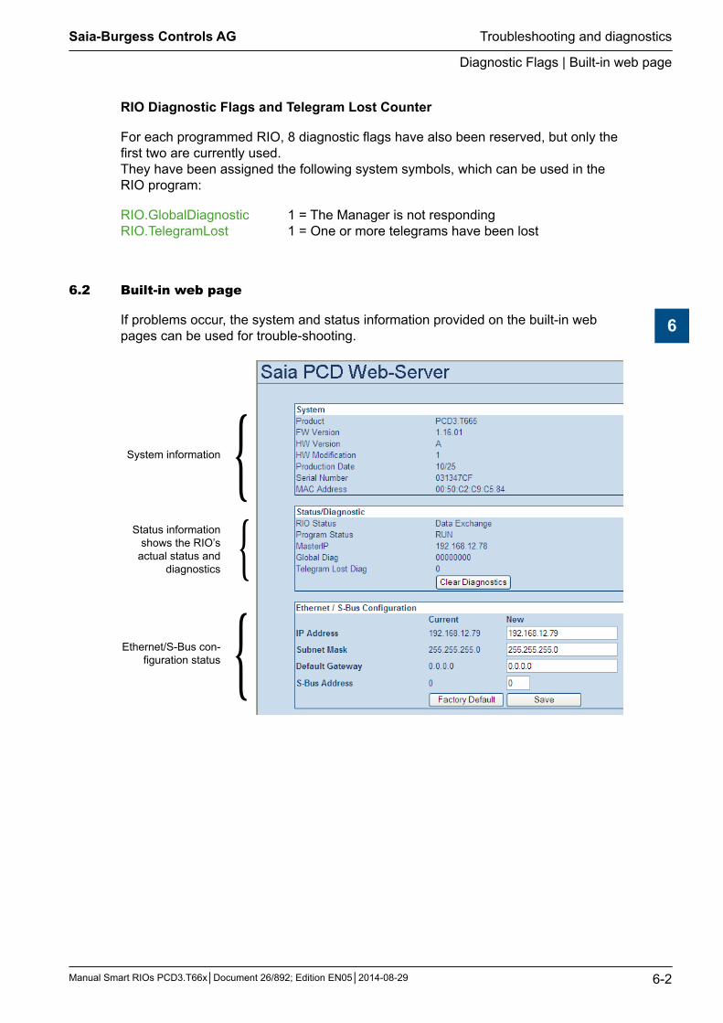
6.2 Built-inwebpage
If problems occur, the system and status information provided on the built-in web pages can be used for trouble-shooting.
System information {Status information
shows the RIO’s actual status and
diagnostics {
Ethernet/S-Bus con-figuration status {
Saia-Burgess Controls AG
Manual Smart RIOs PCD3.T66x│Document 26/892; Edition EN05│2014-08-29
LED display
Troubleshooting and diagnostics
6-3
6
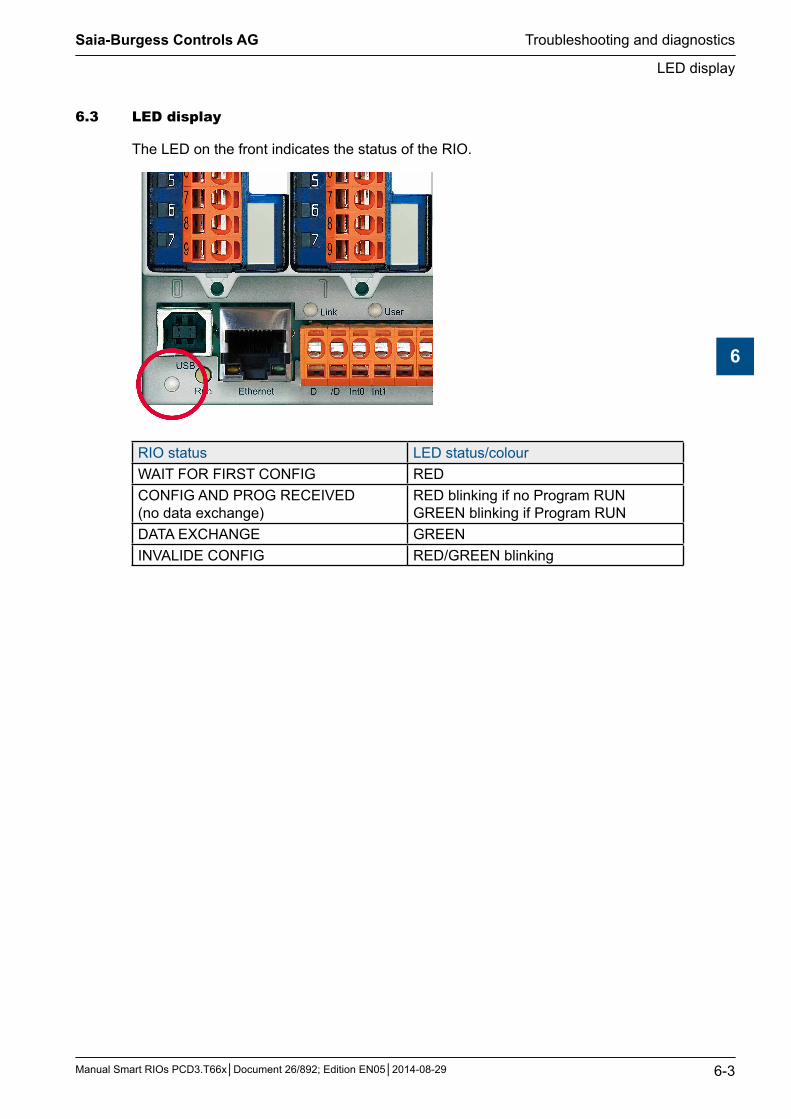
6.3 LEDdisplay
The LED on the front indicates the status of the RIO.
RIO status LED status/colourWAIT FOR FIRST CONFIG REDCONFIG AND PROG RECEIVED (no data exchange)
RED blinking if no Program RUN GREEN blinking if Program RUN
DATA EXCHANGE GREENINVALIDE CONFIG RED/GREEN blinking
Saia-Burgess Controls AG
Manual Smart RIOs PCD3.T66x│Document 26/892; Edition EN05│2014-08-29
Appendix
A-1
Icons
A
A Appendix
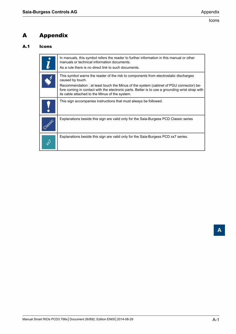
A.1 Icons
In manuals, this symbol refers the reader to further information in this manual or other manuals or technical information documents.As a rule there is no direct link to such documents.
This symbol warns the reader of the risk to components from electrostatic discharges caused by touch.Recommendation : at least touch the Minus of the system (cabinet of PGU connector) be-fore coming in contact with the electronic parts. Better is to use a grounding wrist strap with its cable attached to the Minus of the system.
This sign accompanies instructions that must always be followed.
Explanations beside this sign are valid only for the Saia-Burgess PCD Classic series
Explanations beside this sign are valid only for the Saia-Burgess PCD xx7 series.
Saia-Burgess Controls AG
Manual Smart RIOs PCD3.T66x│Document 26/892; Edition EN05│2014-08-29
Appendix
A-2
Icons
A
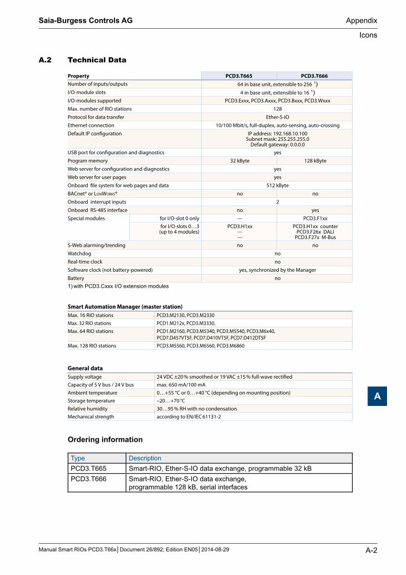
A.2 TechnicalData
Property PCD3.T665 PCD3.T666Number of inputs/outputs 64 in base unit, extensible to 256 1)I/O-module slots 4 in base unit, extensible to 16 1)I/O-modules supported PCD3.Exxx, PCD3.Axxx, PCD3.Bxxx, PCD3.Wxxx
Max. number of RIO stations 128
Protocol for data transfer Ether-S-IO
Ethernet connection 10/100 Mbit/s, full-duplex, auto-sensing, auto-crossing
Default IP configuration IP address: 192.168.10.100Subnet mask: 255.255.255.0
Default gateway: 0.0.0.0 USB port for configuration and diagnostics yes
Program memory 32 kByte 128 kByte
Web server for configuration and diagnostics yes
Web server for user pages yes
Onboard file system for web pages and data 512 kByte
BACnet® or LonWorks® no no
Onboard interrupt inputs 2
Onboard RS-485 interface no yes
Special modules for I/O-slot 0 only --- PCD3.F1xx for I/O-slots 0…3
(up to 4 modules)PCD3.H1xx
------
PCD3.H1xx counterPCD3.F26x DALI
PCD3.F27x M-BusS-Web alarming/trending no no
Watchdog no
Real-time clock no
Software clock (not battery-powered) yes, synchronized by the Manager
Battery no 1) with PCD3.Cxxx I/O extension modules
Smart Automation Manager (master station)Max. 16 RIO stations PCD3.M2130, PCD3.M2330Max. 32 RIO stations PCD1.M212x, PCD3.M3330,Max. 64 RIO stations PCD1.M2160, PCD3.M5340, PCD3.M5540, PCD3.M6x40,
PCD7.D457VT5F, PCD7.D410VT5F, PCD7.D412DT5FMax. 128 RIO stations PCD3.M5560, PCD3.M6560, PCD3.M6860
General dataSupply voltage 24 VDC ±20 % smoothed or 19 VAC ±15 % full-wave rectified Capacity of 5 V bus / 24 V bus max. 650 mA/100 mA Ambient temperature 0…+55 °C or 0…+40 °C (depending on mounting position) Storage temperature –20…+70 °C Relative humidity 30…95 % RH with no condensation Mechanical strength according to EN/IEC 61131-2
Ordering information
Type DescriptionPCD3.T665 Smart-RIO, Ether-S-IO data exchange, programmable 32 kBPCD3.T666 Smart-RIO, Ether-S-IO data exchange,
programmable 128 kB, serial interfaces
Saia-Burgess Controls AG
Manual Smart RIOs PCD3.T66x│Document 26/892; Edition EN05│2014-08-29
Appendix
A-3
Company address of Saia-Burgess
A
A.3 AddressofSaia-BurgessControlsAG
Saia-Burgess Controls AG
Bahnhofstrasse 18 CH-3280 Murten / Schweiz
Telephone ++41 26 672 72 72 Telefax ++41 26 672 74 99 E-mail: [email protected] Homepage: www.saia-pcd.com Support: www.saia-support.com
PostaladdressforreturnsfromcustomersoftheSwissSalesoffice:
Saia-Burgess Controls AG
Service Après-Vente Bahnhofstrasse 18CH-3280 Murten / Schweiz