SMART RELAY SRW 01 V4 - WEG · SMART RELAY. SRW 01 V4.0X . ... P280 – DIGITAL OUTPUT O4 FUNCTION...
31
Motors | Automation | Energy | Transmission & Distribution | Coatings SMART RELAY SRW 01 V4.0X Profibus DP Communication Manual
Transcript of SMART RELAY SRW 01 V4 - WEG · SMART RELAY. SRW 01 V4.0X . ... P280 – DIGITAL OUTPUT O4 FUNCTION...

Motors | Automation | Energy | Transmission & Distribution | Coatings
SMART RELAY
SRW 01 V4.0X Profibus DP Communication Manual


Profibus DP Communication Manual
Series: SRW 01
Firmware Version: V4.0X
Language: English
Document Number: 10000521541 / 05
Publication Date: 12/2012

Summary
ABOUT THIS MANUAL ........................................................................................................................................................6 ABBREVIATIONS AND DEFINITIONS ............................................................................................. 6 NUMERICAL REPRESENTATION .................................................................................................... 6
1 PROFIBUS DP NETWORK ...............................................................................................................................................7 1.1 BAUD RATES......................................................................................................................... 7 1.2 PROFIBUS DP CABLE ............................................................................................................. 7 1.3 CONNECTION OF THE EQUIPMENT TO THE NETWORK ........................................................... 7 1.4 TERMINATION RESISTOR ....................................................................................................... 8 1.5 CONFIGURATION FILE .......................................................................................................... 8
2 ACCESSORY KIT..................................................................................................................................................................9 2.1 PROFIBUS INTERFACE............................................................................................................ 9
2.1.1 Profibus Kit..............................................................................................................................................................9 2.1.2 Connector Pinout ..................................................................................................................................................9
2.2 CONNECTION TO THE NETWORK........................................................................................ 10 2.3 MODULE CONFIGURATION................................................................................................. 10 2.4 STATUS INDICATION .......................................................................................................... 11 2.5 ACCESS TO THE PARAMETERS VIA ACYCLIC DATA ................................................................. 11
3 RELAY PARAMETERIZATION ...................................................................................................................................... 12 P202 – OPERATION MODE ........................................................................................................ 12 P220 – LOCAL/REMOTE SELECTION ........................................................................................... 12 P232 – REMOTE COMMAND SELECTION .................................................................................... 12 P277 – DIGITAL OUTPUT O1 FUNCTION .................................................................................... 13 P278 – DIGITAL OUTPUT O2 FUNCTION .................................................................................... 13 P279 – DIGITAL OUTPUT O3 FUNCTION .................................................................................... 13 P280 – DIGITAL OUTPUT O4 FUNCTION .................................................................................... 13 P281 – DIGITAL OUTPUT O5 FUNCTION .................................................................................... 13 P282 – DIGITAL OUTPUT O6 FUNCTION .................................................................................... 13 P283 – DIGITAL OUTPUT O7 FUNCTION .................................................................................... 13 P284 – DIGITAL OUTPUT O8 FUNCTION .................................................................................... 13 P313 – COMMUNICATION ERROR ACTION ................................................................................ 13 P725 – COMMUNICATION MODULE ADDRESS ........................................................................... 14 P728 – NUMBER OF WORDS FROM THE SLAVE TO THE MASTER ................................................... 14 P729 – STATUS WORD #1 ......................................................................................................... 15 P730 – PARAMETER TRANSMITTED AT WORD #2 ......................................................................... 22 P731 – PARAMETER TRANSMITTED AT WORD #3 ......................................................................... 22 P732 – PARAMETER TRANSMITTED AT WORD #4 ......................................................................... 22 P733 – PARAMETER TRANSMITTED AT WORD #5 ......................................................................... 22 P742 – PARAMETER TRANSMITTED AT WORD #6 ......................................................................... 22 P743 – PARAMETER TRANSMITTED AT WORD #7 ......................................................................... 22 P744 – PARAMETER TRANSMITTED AT WORD #8 ......................................................................... 22 P745 – PARAMETER TRANSMITTED AT WORD #9 ......................................................................... 22 P746 – PARAMETER TRANSMITTED AT WORD #10 ....................................................................... 22 P747 – PARAMETER TRANSMITTED AT WORD #11 ....................................................................... 22 P748 – PARAMETER TRANSMITTED AT WORD #12 ....................................................................... 22 P734 – NUMBER OF WORDS FROM THE MASTER TO THE SLAVE ................................................... 23 P735 – CONTROL WORD #1 ..................................................................................................... 23 P736 – PARAMETER RECEIVED AT WORD #2 ............................................................................... 29 P737 – PARAMETER RECEIVED AT WORD #3 ............................................................................... 29 P738 – PARAMETER RECEIVED AT WORD #4 ............................................................................... 29 P740 – PROFIBUS DP NETWORK STATUS .................................................................................... 29
4 ERRORS RELATED TO THE PROFIBUS DP COMMUNICATION ..................................................................... 30 E0068 – PROFIBUS DP COMMUNICATION TIMEOUT ................................................................... 30 E0069 – PROFIBUS INTERFACE INITIALIZATION ERROR ................................................................ 30

Sumário
E0070 – PARAMETERIZATION DATA ERROR ................................................................................. 30 E0071 – CONFIGURATION DATA ERROR .................................................................................... 31 E0072 – CLEAR MODE .............................................................................................................. 31
About this Manual
6
ABOUT THIS MANUAL This manual provides the necessary information for the operation of the SRW 01 relay in a Profibus DP network. This manual must be used together with the SRW 01 user manual. ABBREVIATIONS AND DEFINITIONS IEC International Electrotechnical Commission PLC Programmable Logic Controller HMI Human-Machine Interface RO Read-only parameter. rw Reading/writing parameter. CFG Configuration parameter, it can only be changed with a stopped motor. Sys System parameter. NUMERICAL REPRESENTATION Decimal numbers are represented by means of digits without suffix. Hexadecimal numbers are represented with the letter ‘h’ after the number.

Profibus DP Network
7
1 PROFIBUS DP NETWORK The term Profibus is used to describe a digital communication system that can be used in several application areas. It is an open and standardized system, defined by the IEC 61158 and IEC 61784 standards, which comprises from the used physical medium to data profiles for certain sets of equipments. In this system, the DP communication protocol was developed with the purpose of allowing a fast, cyclic and deterministic communication between masters and slaves. Among the several communication technologies that can be used in this system, the Profibus DP technology describes a solution that, typically, is composed by the DP protocol, RS485 transmission medium and application profiles, used mainly in applications and equipments with emphasis in manufacturing automation. Nowadays, there is an organization named Profibus International, responsible for keeping, updating and publishing the Profibus technology among users and members. More information regarding the technology, as well as the complete protocol specification can be obtained with this organization or with one of the regional associations or competence centers associated to the Profibus International (http://www.profibus.com). 1.1 BAUD RATES The Profibus DP protocol defines several baud rates that can be used, from 9.6 kbit/s up to 12Mbit/s. The maximum allowed transmission line length depends on the used baud rate, and this correlation is showed on the table 1.1.
Table 1.1 – Baud rate x Segment length
Baud Rate (kbit/s)
Segment length - m (ft)
9.6; 19.2; 45.45; 93.75 1200 (3936.99) 187.5 1000 (3280.83)
500 400 (1312.33) 1500 200 (656.16)
3000, 6000, 12000 100 (328.08)
The SRW 01 communication module has automatic baud rate detection, according to what has been configured for the network master, and therefore it is not necessary to configure this option. 1.2 PROFIBUS DP CABLE It is recommended that the installation be carried out with a type A cable, whose characteristics are described in the table 1.2. The cable has a pair of wires that must be shielded and twisted, in order to guarantee higher immunity against electromagnetic interference.
Table 1.2 – Type A cable properties
Impedance 135 to 165 ohms Capacitance 30 pF/m Loop resistance 110 ohms/km Cable diameter > 0.64 mm Wire cross section > 0.34 mm2
1.3 CONNECTION OF THE EQUIPMENT TO THE NETWORK The Profibus DP protocol, by using the RS485 physical medium, allows the connection of up to 32 devices per segment without the use of repeaters. By using repeaters, up to 126 addressable equipments can be connected to the network. Each repeater must also be included as a device connected to the segment, even not occupying a network address. It is recommended that the connection of all the devices present in the Profibus DP network be made coming from the main bus. Generally, the Profibus network connector itself has an input and an output for the cable, allowing

Profibus DP Network
8
the connection to be taken to the other network points. Derivations from the main bus are not recommended, especially for baud rates higher or equal to 1.5Mbits/s. The Profibus DP network cables must be laid separately (and far away if possible) from the power section cables. All the devices must be properly grounded, preferably at the same ground point. The Profibus cable shield must also be grounded. 1.4 TERMINATION RESISTOR At each segment of the Profibus DP network, it is necessary to enable a termination resistor at the extreme points of the main bus. The Profibus DP network connector normally has a switch to enable the termination resistor. It is important to emphasize that in order to be possible to disconnect the element from the network without impairing the bus, it becomes interesting the use of active terminations, which are elements that have only the termination function. Therefore, any equipment of the network can be disconnected from the bus without impairing the termination. 1.5 CONFIGURATION FILE Each element of the Profibus DP network has an associated configuration file with the GSD extension. This file describes the characteristics of each device, and it is used by the Profibus DP network master configuration tool. During the master configuration the GSD configuration file supplied with the equipment must be used.

Accessory Kit
9
2 ACCESSORY KIT In order to make the Profibus DP communication possible with the SRW 01 smart relay, it is necessary to use a Profibus DP communication kit, according to the description below. Information on the installation of this module in the relay can be obtained in the installation guide that comes with the kit. 2.1 PROFIBUS INTERFACE 2.1.1 Profibus Kit
It is composed by the Profibus communication module (figure at the left) and a installation guide.
The interface is galvanically isolated and with differential signal, granting more robustness against electromagnetic interference.
2.1.2 Connector Pinout Once the Profibus DP communication kit has been installed, the relay makes available two different connectors for the interface with the network:
Female DB9 connector (XC15). 8-wire plug-in terminal strip (XC2).
Table 2.1 – Profibus interface DB9 connector (XC15) pinout
Pin Signal Function 1 - Reserved (do not connect) 2 - Reserved (do not connect) 3 B B signal (red) 4 - Reserved (do not connect) 5 GND Profibus DP interface isolated reference
6 +5V +5 V output isolated from the Profibus interface
7 - Reserved (do not connect) 8 A A signal (green) 9 - Reserved (do not connect)
Table 2.2 – Profibus interface 8-wire plug-in
terminal strip pinout
Pin Signal Function A A A signal (green) B B B signal (red) PE PE Protective Earth/Cable shield BK RTS Request To Send BU - Reserved (do not connect) SH GND Profibus DP interface isolated reference WH - Reserved (do not connect)
RD +5V +5 V output isolated from the Profibus interface
XC2
XC15

Accessory Kit
10
2.2 CONNECTION TO THE NETWORK The following points must be observed for the connection of the relay using the Profibus interface: Installation of termination resistors only at the main bus extremes, even if there are derivations. Do not use derivations for baud rates higher than 1.5 Mbit/s. The RTS signal is available only at the 8-wire XC2 terminal strip. This signal can be used, for instance, for the
connection with an external fiber optics converter.
Figure 1: Example of connection to Profibus DP network.
2.3 MODULE CONFIGURATION In order to configure the Profibus module, follow the steps indicated below: With the relay deenergized, install the Profibus communication module in the slot located on the equipment
bottom. Energize the relay. By using the WLP software connected to the SRW 01 via USB interface or an SRW 01 HMI, verify the content of
the parameter P084, which will indicate whether the communication module has been correctly detected (P084 = 3). If necessary, refer to the installation guide and to the user manual.
Adjust the relay network address through the parameter P725. - Valid values for the Profibus network: 1 to 125.
Configure the number of input and output words at the parameters P728 and P734, respectively. This exact number of words must be adjusted at the network master.
According to the number of configured input and output words, adjust also the parameters P730 to P733 and P736.
Cycle the power of the SRW 01 so that the changes become effective. Connect the network cable. Register the configuration file (GSD file) in the network configuration software. In the network configuration software, add the SRW 01 to the list of devices connected to the network and
select the I/O data module that represents the number of input and output words programmed at the parameters P728 and P734.
ATTENTION! Terminal strip XC2 pin PE must obligatorily be connected to a protective earth, as shown in figure 01, even if the used connector is DB9 (XC15).
Accessory Kit
11
If everything is configured correctly, the parameter P740 will indicate the “Online” state. In this situation the NET LED must be steadily on in green.
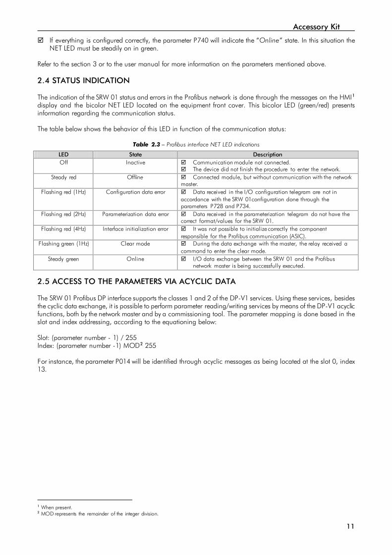
Refer to the section 3 or to the user manual for more information on the parameters mentioned above. 2.4 STATUS INDICATION The indication of the SRW 01 status and errors in the Profibus network is done through the messages on the HMI1 display and the bicolor NET LED located on the equipment front cover. This bicolor LED (green/red) presents information regarding the communication status. The table below shows the behavior of this LED in function of the communication status:
Table 2.3 – Profibus interface NET LED indications
LED State Description Off Inactive Communication module not connected.
The device did not finish the procedure to enter the network. Steady red Offline Connected module, but without communication with the network
master. Flashing red (1Hz) Configuration data error Data received in the I/O configuration telegram are not in
accordance with the SRW 01configuration done through the parameters P728 and P734.
Flashing red (2Hz) Parameterization data error Data received in the parameterization telegram do not have the correct format/values for the SRW 01.
Flashing red (4Hz) Interface initialization error It was not possible to initialize correctly the component responsible for the Profibus communication (ASIC).
Flashing green (1Hz) Clear mode During the data exchange with the master, the relay received a command to enter the clear mode.
Steady green Online I/O data exchange between the SRW 01 and the Profibus network master is being successfully executed.
2.5 ACCESS TO THE PARAMETERS VIA ACYCLIC DATA The SRW 01 Profibus DP interface supports the classes 1 and 2 of the DP-V1 services. Using these services, besides the cyclic data exchange, it is possible to perform parameter reading/writing services by means of the DP-V1 acyclic functions, both by the network master and by a commissioning tool. The parameter mapping is done based in the slot and index addressing, according to the equationing below: Slot: (parameter number - 1) / 255 Index: (parameter number -1) MOD2 255 For instance, the parameter P014 will be identified through acyclic messages as being located at the slot 0, index 13.
1 When present. 2 MOD represents the remainder of the integer division.

Relay Parameterization
12
3 RELAY PARAMETERIZATION Next, only the SRW 01 relay parameters related to the Profibus DP communication will be presented. The detailed description of this parameter is found in the SRW 01 User Manual. P202 – Operation Mode
Adjustable 0 = Transparent Factory default: 1 range: 1 = Overload Relay 2 = Direct Start 3 = Reverse Start 4 = Star-Delta Start 5 = Dahlander Start 6 = Pole-Changing Start 7 = PLC Mode
Properties: Sys, CFG
Description: This parameter allows selecting the SRW 01 operation mode. The functions of digital inputs and outputs are configured automatically according to this selection. P220 – Local/Remote Selection
Adjustable 0 = Always Local Factory default: 2 Range: 1 = Always Remote 2 = HMI key (LOC) 3 = HMI key (REM) 4 = Digital Input I3 5 = Digital Input I4 6 = Fieldbus (LOC) 7 = Fieldbus (REM) 8 = USB/Ladder
Properties: Sys, rw
Description: This parameter defines the origin of the command that will select the SRW 01 working mode (Local/Remote) and its initial state. P232 – Remote Command Selection
Adjustable 0 = Ix Factory default: 3 Range: 1 = HMI 2 = USB/Ladder 3 = Fieldbus
Properties: Sys, rw
Description: It defines the origin of the remote commands. If P232 = 3, the remote commands are controlled by the industrial network master.

Relay Parameterization
13
P277 – Digital Output O1 Function
P278 – Digital Output O2 Function
P279 – Digital Output O3 Function
P280 – Digital Output O4 Function
P281 – Digital Output O5 Function
P282 – Digital Output O6 Function
P283 – Digital Output O7 Function
P284 – Digital Output O8 Function
Adjustable 0 = Internal use (P202) Factory default: 1 Range: 1 = Ladder 2 = Fieldbus 3 = Alarm/Fault (NO) Signal 4 = Trip/Error (NO) Signal 5 = Trip/Error (NC) Signal
Properties: Sys, CFG
Description: They define the relay output control origin. Internal Use: it is used according to selected operation mode (P202); Ladder: it is used by the user program implemented in Ladder; F ieldbus: it is used directly by the industrial network master. Alarm/Fault (NO) Signal: it is used to signal Alarm or Fault. In case of Alarm or Fault the output is closed, remaining like this until the cause of failure is not present anymore and the reset control is set. Trip/Error (NO) Signal: it is used to signal Trip or Error. In case of Trip or Error (Ex. No communication with the Current Measuring Unit) the output is closed, remaining this until the cause of the failure is not present anymore and the reset control is set. Trip/Error (NC) Signal: it is used to signal Trip or Error. In case of Trip or Error (Ex. No communication with the Current Measuring Unit) the output is closed, remaining like this until the cause of the failure is not present anymore and the reset control is set.
NOTE! It is worthwhile to remember that the availability of the digital outputs (O1-O4) depends on the used operation mode (P202), because it is possible that one or more outputs be already pre-allocated for other functions.
P313 – Communication Error Action
Adjustable 0 = Only Fault Indication Factory Setting: 0 Range: 1 = The Motor is Switched Off 2 = The Motor is Switched Off and the Commands are Reset 3 = It Changes to Local
Properties Sys, rw
Description: This parameter allows selecting which action must be executed by the smart relay if a communication error is detected.

Relay Parameterization
14
Table 3.1 – Values for the parameter P313
Options Description 0 = Only indicates fault Fault indication only with no action taken. The
indication of fault will be automatically removed if the fault condition is cleared and the relay status are not either TRIP or Error. If the relay status is TRIP or Error, it is mandatory to perform “error reset” in order to remove the fault indication.
1 = Stops motor It switches the motor off, for the operation modes where this commands exists. It is necessary to perform the error reset in order to remove the indication.
2 = Stops motor and resets commands
It switches the motor off and resets the commands. It is necessary to perform the error reset in order to remove the indication.
3 = Goes to local It changes to local mode, providing that the local/remote selection is programmed to be executed via Fieldbus. The indication of fault will be automatically removed if the fault condition is cleared and the relay status are not either TRIP or Error. If the relay status is TRIP or Error, it is mandatory to perform “error reset” in order to remove the fault indication.
The following events are considered communication errors for the Profibus DP interface: E0068: Timeout in the I/O data communication of the Profibus interface has occurred. E0069: Profibus ASIC initialization error. E0070: The Profibus parameterization telegram data are incorrect. E0071: The Profibus I/O configuration telegram data are incorrect. E0072: The relay has received a command to enter the Clear mode. The description of these errors is done in the section 4. P725 – Communication Module Address
Adjustable 0 to 255 Factory Setting: 63 Range:
Properties Sys, CFG
Description: It allows programming the relay communication module address. It is necessary that each network device has an address different from the others. The valid addresses for this parameter depend on the used protocol: Modbus → valid addresses: 1 to 247. DeviceNet → valid addresses: 0 to 63. Profibus → valid addresses: 1 to 125. If this parameter is changed, it becomes valid only after cycling the power of the relay. P728 – Number of Words from the Slave to the Master
Adjustable 1 to 12 Factory Setting: 1 Range:
Properties Sys, rw
Description: It allows selecting the number of input words exchanged with the master. Each word has the following meaning:

Relay Parameterization
15
1st Word: It represents the status word, which depends on the chosen operation mode. In order to make the diagnosis easier, the content of this parameter is showed at the parameter P729. 2nd to 12nd Word: Content sent to the master, programmable by using the parameters P730 to P733 and P742 to P748.
NOTE! If the parameter P728 is changed, it will only become effective after cycling the power of the relay.
P729 – Status Word #1
Adjustable 0000h – FFFFh Factory Setting: - Range:
Properties RO
Description: It allows monitoring the relay status. The content of this parameter is transmitted to the Profibus DP network master, always at the first input word. The format of this word depends on the SRW 01 operation mode, programmed at the parameter P202. Transparent Mode (P202 = 0): Monitoring (Input)
Bits 15 to 13 12 11 10 9 8 7 6 5 4 3 2 1 0
Function
Rese
rved
O4
outp
ut s
tate
O3
outp
ut s
tate
O2
outp
ut s
tate
O1
outp
ut s
tate
I4 in
put s
tate
I3 in
put s
tate
I2 in
put s
tate
I1 in
put s
tate
Rem
ote
Mod
e
Mot
or O
n
Ala
rm/F
ault
Trip
Erro
r
Bits (Byte 0 and 1) Values
Bit 0 Error
0: the relay is not in error condition 1: the relay is in error condition Note: The error number can be read via the parameter P016 – Current Error
Bit 1 Trip
0: the relay is not in the trip condition 1: the relay is in the trip condition Note: The trip fault number can be read via the parameter P016 - Current Error
Bit 2 Alarm/Fault
0: the relay is not in the alarm/fault condition 1: the relay is in the alarm/fault condition Note: The alarm/fault number can be read via the parameter P016 – Current Error
Bit 3 Motor On
0: motor Off 1: Motor On
Bit 4 Remote Mode
0: changes to Local Mode 1: changes to Remote Mode
Bit 5 I1 Input state
0: I1 digital input is deactivated 1: I1 digital input is activated
Bit 6 I2 input state
0: I2 digital input is deactivated 1: I2 digital input is activated
Bit 7 I3 input state
0: I3 digital input is deactivated 1: I3 digital input is activated
Bit 8 I4 input state
0: I4 digital input is deactivated 1: I4 digital input is activated
Bit 9 O1 output state
0: O1 digital output is deactivated 1: O1 digital output is activated
Bit 10 O2 output state
0: O2 digital output is deactivated 1: O2 digital output is activated
Bit 11 O3 output state
0: O3 digital output is deactivated 1: O3 digital output is activated
Bit 12 O4 output state
0: O4 digital output is deactivated 1: O4 digital output is activated
Relay Parameterization
16
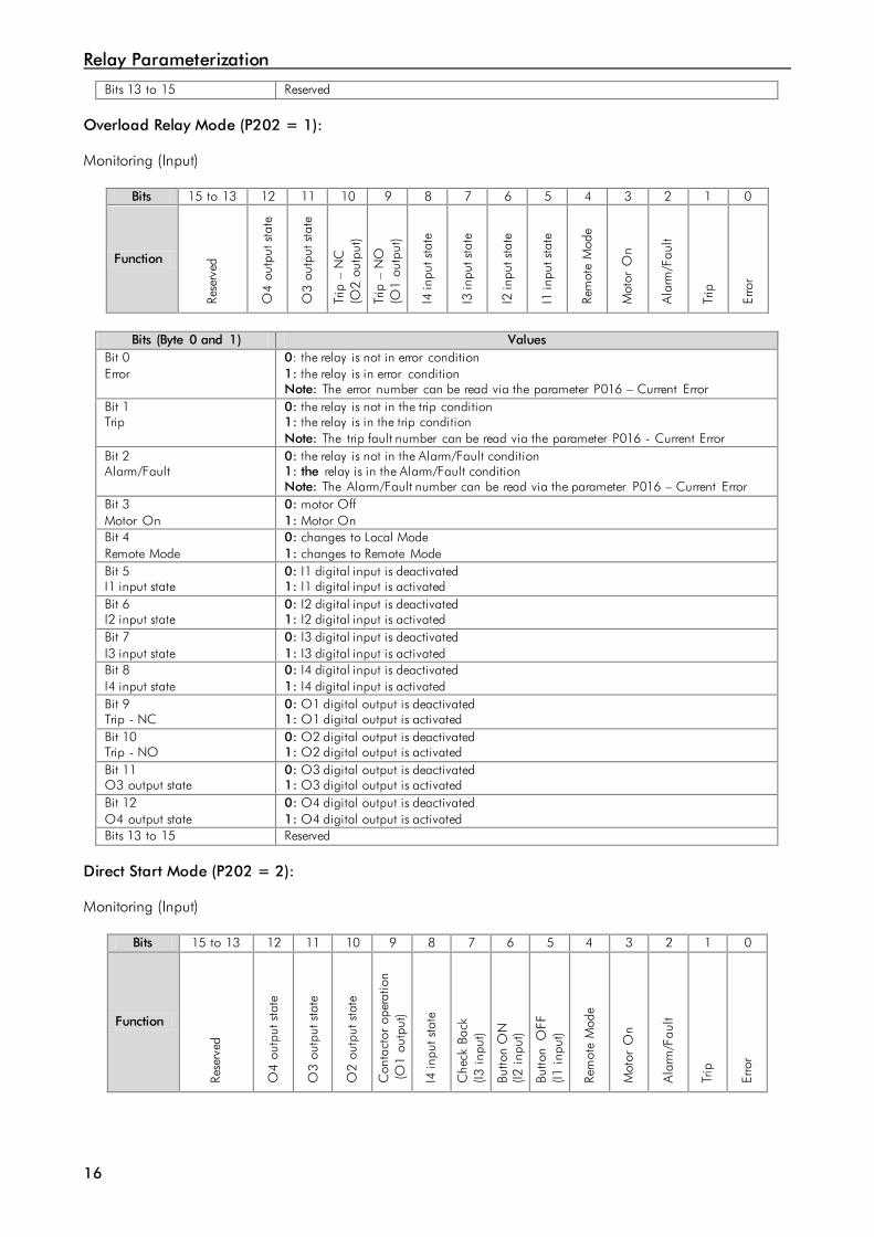
Bits 13 to 15 Reserved Overload Relay Mode (P202 = 1): Monitoring (Input)
Bits 15 to 13 12 11 10 9 8 7 6 5 4 3 2 1 0
Function
Rese
rved
O4
outp
ut s
tate
O3
outp
ut s
tate
Trip
– N
C
(O2
outp
ut)
Trip
– N
O
(O1
outp
ut)
I4 in
put s
tate
I3 in
put s
tate
I2 in
put s
tate
I1 in
put s
tate
Rem
ote
Mod
e
Mot
or O
n
Ala
rm/F
ault
Trip
Erro
r
Bits (Byte 0 and 1) Values
Bit 0 Error
0: the relay is not in error condition 1: the relay is in error condition Note: The error number can be read via the parameter P016 – Current Error
Bit 1 Trip
0: the relay is not in the trip condition 1: the relay is in the trip condition Note: The trip fault number can be read via the parameter P016 - Current Error
Bit 2 Alarm/Fault
0: the relay is not in the Alarm/Fault condition 1: the relay is in the Alarm/Fault condition Note: The Alarm/Fault number can be read via the parameter P016 – Current Error
Bit 3 Motor On
0: motor Off 1: Motor On
Bit 4 Remote Mode
0: changes to Local Mode 1: changes to Remote Mode
Bit 5 I1 input state
0: I1 digital input is deactivated 1: I1 digital input is activated
Bit 6 I2 input state
0: I2 digital input is deactivated 1: I2 digital input is activated
Bit 7 I3 input state
0: I3 digital input is deactivated 1: I3 digital input is activated
Bit 8 I4 input state
0: I4 digital input is deactivated 1: I4 digital input is activated
Bit 9 Trip - NC
0: O1 digital output is deactivated 1: O1 digital output is activated
Bit 10 Trip - NO
0: O2 digital output is deactivated 1: O2 digital output is activated
Bit 11 O3 output state
0: O3 digital output is deactivated 1: O3 digital output is activated
Bit 12 O4 output state
0: O4 digital output is deactivated 1: O4 digital output is activated
Bits 13 to 15 Reserved Direct Start Mode (P202 = 2): Monitoring (Input)
Bits 15 to 13 12 11 10 9 8 7 6 5 4 3 2 1 0
Function
Rese
rved
O4
outp
ut s
tate
O3
outp
ut s
tate
O2
outp
ut s
tate
Con
tact
or o
pera
tion
(O1
outp
ut)
I4 in
put s
tate
Che
ck B
ack
(I3
inp
ut)
Butto
n O
N
(I2 i
nput
)
Butto
n O
FF
(I1 i
nput
)
Rem
ote
Mod
e
Mot
or O
n
Ala
rm/F
ault
Trip
Erro
r
Relay Parameterization
17
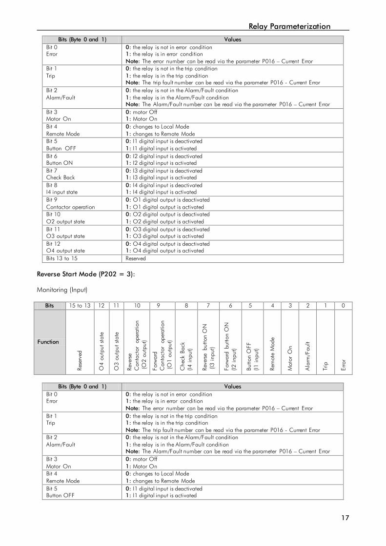
Bits (Byte 0 and 1) Values Bit 0 Error
0: the relay is not in error condition 1: the relay is in error condition Note: The error number can be read via the parameter P016 – Current Error
Bit 1 Trip
0: the relay is not in the trip condition 1: the relay is in the trip condition Note: The trip fault number can be read via the parameter P016 - Current Error
Bit 2 Alarm/Fault
0: the relay is not in the Alarm/Fault condition 1: the relay is in the Alarm/Fault condition Note: The Alarm/Fault number can be read via the parameter P016 – Current Error
Bit 3 Motor On
0: motor Off 1: Motor On
Bit 4 Remote Mode
0: changes to Local Mode 1: changes to Remote Mode
Bit 5 Button OFF
0: I1 digital input is deactivated 1: I1 digital input is activated
Bit 6 Button ON
0: I2 digital input is deactivated 1: I2 digital input is activated
Bit 7 Check Back
0: I3 digital input is deactivated 1: I3 digital input is activated
Bit 8 I4 input state
0: I4 digital input is deactivated 1: I4 digital input is activated
Bit 9 Contactor operation
0: O1 digital output is deactivated 1: O1 digital output is activated
Bit 10 O2 output state
0: O2 digital output is deactivated 1: O2 digital output is activated
Bit 11 O3 output state
0: O3 digital output is deactivated 1: O3 digital output is activated
Bit 12 O4 output state
0: O4 digital output is deactivated 1: O4 digital output is activated
Bits 13 to 15 Reserved Reverse Start Mode (P202 = 3): Monitoring (Input)
Bits 15 to 13 12 11 10 9 8 7 6 5 4 3 2 1 0
Function
Rese
rved
O4
outp
ut s
tate
O3
outp
ut s
tate
Reve
rse
C
onta
ctor
op
erat
ion
(O2
outp
ut)
Forw
ard
C
onta
ctor
op
erat
ion
(O1
outp
ut)
Che
ck B
ack
(I4
inp
ut)
Reve
rse
butto
n O
N
(I3
inpu
t)
Forw
ard
butto
n O
N
(I2 i
nput
)
Butto
n O
FF
(I1 i
nput
)
Rem
ote
Mod
e
Mot
or O
n
Ala
rm/F
ault
Trip
Erro
r
Bits (Byte 0 and 1) Values
Bit 0 Error
0: the relay is not in error condition 1: the relay is in error condition Note: The error number can be read via the parameter P016 – Current Error
Bit 1 Trip
0: the relay is not in the trip condition 1: the relay is in the trip condition Note: The trip fault number can be read via the parameter P016 - Current Error
Bit 2 Alarm/Fault
0: the relay is not in the Alarm/Fault condition 1: the relay is in the Alarm/Fault condition Note: The Alarm/Fault number can be read via the parameter P016 – Current Error
Bit 3 Motor On
0: motor Off 1: Motor On
Bit 4 Remote Mode
0: changes to Local Mode 1: changes to Remote Mode
Bit 5 Button OFF
0: I1 digital input is deactivated 1: I1 digital input is activated

Relay Parameterization
18
Bit 6 Forward button ON
0: I2 digital input is deactivated 1: I2 digital input is activated
Bit 7 Reverse button ON
0: I3 digital input is deactivated 1: I3 digital input is activated
Bit 8 Check Back
0: I4 digital input is deactivated 1: I4 digital input is activated
Bit 9 Forward Contactor operation
0: O1 digital output is deactivated 1: O1 digital output is activated
Bit 10 Reverse Contactor operation
0: O2 digital output is deactivated 1: O2 digital output is activated
Bit 11 O3 output state
0: O3 digital output is deactivated 1: O3 digital output is activated
Bit 12 O4 output state
0: O4 digital output is deactivated 1: O4 digital output is activated
Bits 13 to 15 Reserved Star-Delta Starter (P202 = 4): Monitoring (Input)
Bits 15 to 13 12 11 10 9 8 7 6 5 4 3 2 1 0
Function
Rese
rved
O4
outp
ut s
tate
K3 S
tar C
onta
ctor
op
erat
ion
(O3
outp
ut)
K2 D
elta
Con
tact
or
oper
atio
n (O
2 ou
tput
) K1
Con
tact
or
oper
atio
n (O
1 ou
tput
)
Che
ck B
ack
K1-K
3
(I4 i
nput
)
Che
ck B
ack
K1-K
2
(I3 i
nput
)
Butto
n O
N
(I2
inpu
t)
Butto
n O
FF
(I1 i
nput
)
Rem
ote
Mod
e
Mot
or O
n
Ala
rm/F
ault
Trip
Erro
r
Bits (Byte 0 and 1) Values
Bit 0 Error
0: the relay is not in error condition 1: the relay is in error condition Note: The error number can be read via the parameter P016 – Current Error
Bit 1 Trip
0: the relay is not in the trip condition 1: the relay is in the trip condition Note: The trip fault number can be read via the parameter P016 - Current Error
Bit 2 Alarm/Fault
0: the relay is not in the Alarm/Fault condition 1: the relay is in the Alarm/Fault condition Note: The Alarm/Fault number can be read via the parameter P016 – Current Error
Bit 3 Motor On
0: motor Off 1: Motor On
Bit 4 Remote Mode
0: changes to Local Mode 1: changes to Remote Mode
Bit 5 Button OFF
0: I1 digital input is deactivated 1: I1 digital input is activated
Bit 6 Button ON
0: I2 digital input is deactivated 1: I2 digital input is activated
Bit 7 Check Back K1-K2
0: I3 digital input is deactivated 1: I3 digital input is activated
Bit 8 Check Back K1-K3
0: I4 digital input is deactivated 1: I4 digital input is activated
Bit 9 K1 Contactor operation
0: O1 digital output is deactivated 1: O1 digital output is activated
Bit 10 K2 - Delta Contactor operation
0: O2 digital output is deactivated 1: O2 digital output is activated
Bit 11 K3 - Star Contactor operation
0: O3 digital output is deactivated 1: O3 digital output is activated

Relay Parameterization
19
Bit 12 O4 output state
0: O4 digital output is deactivated 1: O4 digital output is activated
Bits 13 to 15 Reserved Dahlander Starter (P202 = 5): Monitoring (Input)
Bits 15 to 13 12 11 10 9 8 7 6 5 4 3 2 1 0
Function
Rese
rved
O4
outp
ut s
tate
K3 H
igh
spee
d C
onta
ctor
op
erat
ion
(O3
outp
ut)
K2 H
igh
spee
d C
onta
ctor
op
erat
ion
(O2
outp
ut)
K1 L
ow s
peed
C
onta
ctor
op
erat
ion
(O1
outp
ut)
Che
ck B
ack
(I4 in
put)
Low
spe
ed S
TART
bu
tton
(I3 i
nput
)
Hig
h sp
eed
STA
RT
butto
n (I2
inp
ut)
Butto
n O
FF
(I1 i
nput
)
Rem
ote
Mod
e
Mot
or O
n
Ala
rm/F
ault
Trip
Erro
r
Bits (Byte 0 and 1) Values
Bit 0 Error
0: the relay is not in error condition 1: the relay is in error condition Note: The error number can be read via the parameter P016 – Current Error
Bit 1 Trip
0: the relay is not in the trip condition 1: the relay is in the trip condition Note: The trip fault number can be read via the parameter P016 - Current Error
Bit 2 Alarm/Fault
0: the relay is not in the Alarm/Fault condition 1: the relay is in the Alarm/Fault condition Note: The Alarm/Fault number can be read via the parameter P016 – Current Error
Bit 3 Motor On
0: motor Off 1: Motor On
Bit 4 Remote Mode
0: changes to Local Mode 1: changes to Remote Mode
Bit 5 Button OFF
0: I1 digital input is deactivated 1: I1 digital input is activated
Bit 6 High speed START button
0: I2 digital input is deactivated 1: I2 digital input is activated
Bit 7 Low speed START button
0: I3 digital input is deactivated 1: I3 digital input is activated
Bit 8 Check Back
0: I4 digital input is deactivated 1: I4 digital input is activated
Bit 9 K1- Low speed Contactor operation
0: O1 digital output is deactivated 1: O1 digital output is activated
Bit 10 K2 - High speed Contactor operation
0: O2 digital output is deactivated 1: O2 digital output is activated
Bit 11 K3 - High speed Contactor operation
0: O3 digital output is deactivated 1: O3 digital output is activated
Bit 12 O4 output state
0: O4 digital output is deactivated 1: O4 digital output is activated
Bits 13 to 15 Reserved

Relay Parameterization
20
Pole-Changing Starter (P202 = 6): Monitoring (Input)
Bits 15 to 13 12 11 10 9 8 7 6 5 4 3 2 1 0
Function
Rese
rved
O4
outp
ut s
tate
O3
outp
ut s
tate
K1 H
igh
spee
d C
onta
ctor
op
erat
ion
(O2
outp
ut)
K2 L
ow s
peed
C
onta
ctor
op
erat
ion
(O1
outp
ut)
Che
ck B
ack
K1
– K2
(I4
inp
ut)
Low
spe
ed S
TART
bu
tton
(I3 i
nput
)
Hig
h sp
eed
STA
RT
butto
n (I2
inp
ut)
Butto
n O
FF
(I1 i
nput
)
Rem
ote
Mod
e
Mot
or O
n
Ala
rm/F
ault
Trip
Erro
r
Bits (Byte 0 and 1) Values
Bit 0 Error
0: the relay is not in error condition 1: the relay is in error condition Note: The error number can be read via the parameter P016 – Current Error
Bit 1 Trip
0: the relay is not in the trip condition 1: the relay is in the trip condition Note: The trip fault number can be read via the parameter P016 - Current Error
Bit 2 Alarm/Fault
0: the relay is not in the Alarm/Fault condition 1: the relay is in the Alarm/Fault condition Note: The Alarm/Fault number can be read via the parameter P016 – Current Error
Bit 3 Motor On
0: motor Off 1: motor On
Bit 4 Remote Mode
0: changes to Local Mode 1: changes to Remote Mode
Bit 5 Button OFF
0: I1 digital input is deactivated 1: I1 digital input is activated
Bit 6 High speed START button
0: I2 digital input is deactivated 1: I2 digital input is activated
Bit 7 Low speed START button
0: I3 digital input is deactivated 1: I3 digital input is activated
Bit 8 Check Back K1-K2
0: I4 digital input is deactivated 1: I4 digital input is activated
Bit 9 K2- Low speed Contactor operation
0: O1 digital output is deactivated 1: O1 digital output is activated
Bit 10 K1 - High speed Contactor operation
0: O2 digital output is deactivated 1: O2 digital output is activated
Bit 11 O3 output state
0: O3 digital output is deactivated 1: O3 digital output is activated
Bit 12 O4 output state
0: O4 digital output is deactivated 1: O4 digital output is activated
Bits 13 to 15 Reserved PLC Mode (P202 = 7): Monitoring (Input)
Bits 15 to 13 12 11 10 9 8 7 6 5 4 3 2 1 0
Function
Rese
rved
O4
outp
ut s
tate
O3
outp
ut s
tate
O2
outp
ut s
tate
O1
outp
ut s
tate
I4 in
put s
tate
I3 in
put s
tate
I2 in
put s
tate
I1 in
put s
tate
Rem
ote
Mod
e
Mot
or O
n
Ala
rm/F
ault
Trip
Erro
r

Relay Parameterization
21
Bits (Byte 0 and 1) Values Bit 0 Error
0: the relay is not in error condition 1: the relay is in error condition Note: The error number can be read via the parameter P016 – Current Error
Bit 1 Trip
0: the relay is not in the trip condition 1: the relay is in the trip condition Note: The trip fault number can be read via the parameter P016 - Current Error
Bit 2 Alarm/Fault
0: the relay is not in the Alarm/Fault condition 1: the relay is in the Alarm/Fault condition Note: The Alarm/Fault number can be read via the parameter P016 – Current Error
Bit 3 Reserved Bit 4 Remote Mode
0: changes to Local Mode 1: changes to Remote Mode
Bit 5 I1 input State
0: I1 digital input is deactivated 1: I1 digital input is activated
Bit 6 I2 input State
0: I2 digital input is deactivated 1: I2 digital input is activated
Bit 7 I3 input State
0: I3 digital input is deactivated 1: I3 digital input is activated
Bit 8 I4 input State
0: I4 digital input is deactivated 1: I4 digital input is activated
Bit 9 O1 output state
0: O1 digital output is deactivated 1: O1 digital output is activated
Bit 10 O2 output state
0: O2 digital output is deactivated 1: O2 digital output is activated
Bit 11 O3 output state
0: O3 digital output is deactivated 1: O3 digital output is activated
Bit 12 O4 output state
0: O4 digital output is deactivated 1: O4 digital output is activated
Bits 13 to 15 Reserved

Relay Parameterization
22
P730 – Parameter Transmitted at Word #2
P731 – Parameter Transmitted at Word #3
P732 – Parameter Transmitted at Word #4
P733 – Parameter Transmitted at Word #5
P742 – Parameter Transmitted at Word #6
P743 – Parameter Transmitted at Word #7
P744 – Parameter Transmitted at Word #8
P745 – Parameter Transmitted at Word #9
P746 – Parameter Transmitted at Word #10
P747 – Parameter Transmitted at Word #11
P748 – Parameter Transmitted at Word #12
Adjustable 0 a 899 Factory Setting::P730 = 16 Range:: P731 = 80 P732 = 81 P733 = 3 P742 = 30 P743 = 31 P744 = 32 P745 = 50 P746 = 0 P747 = 0 P748 = 0
Properties Sys, rw
Description: These parameters allow the user to program the reading of any other parameter of the equipment via the network. In other words, they contain the number of another parameter. For instance, P730 = 5. In this case the content of P005 (Line Frequency) will be sent through the network. Thus, in the network master memory position correspondent to the second reading word, the line frequency will be read.

Relay Parameterization
23
Function P728 Option
Status Word #1 1 2
3 4
5 6
7 8
9 10
11 12
Parameter Transmitted at Word #2 (content of the parameter indicated in P730)
Parameter Transmitted at Word #3 (content of the parameter indicated in P731)
Parameter Transmitted at Word #4 (content of the parameter indicated in P732)
Parameter Transmitted at Word #5 (content of the parameter indicated in P733)
Parameter Transmitted at Word #6 (content of the parameter indicated in P742)
Parameter Transmitted at Word #7 (content of the parameter indicated in P743)
Parameter Transmitted at Word #8 (content of the parameter indicated in P744)
Parameter Transmitted at Word #9 (content of the parameter indicated in P745)
Parameter Transmitted at Word #10 (content of the parameter indicated in P746)
Parameter Transmitted at Word #11 (content of the parameter indicated in P747)
Parameter Transmitted at Word #12 (content of the parameter indicated in P748)
P734 – Number of Words from the Master to the Slave
Adjustable 1 to 4 Factory Setting: 1 Range:
Properties Sys, rw
Description: It allows selecting the number of output words exchanged with the master. Each word has the following meaning: 1st Word: It represents the control word, which depends on the chosen operation mode. In order to make the diagnosis easier, the content of this parameter is showed at the parameter P735. 2nd Word: Content sent to the relay, programmable by using the parameter P736. 3rd Word: Content sent to the relay, programmable by using the parameter P737. 4th Word: Content sent to the relay, programmable by using the parameter P738.
NOTE! If the parameter P734 is changed, it will only become effective after cycling the power of the relay.
P735 – Control Word #1
Adjustable 0000h – FFFFh Factory Setting: 0000h Range:
Properties RO
Description: It is the relay control word through the Profibus DP interface. This parameter can only be changed via the Profibus interface. For the other sources (HMI, USB, Serial, etc.) it behaves like a read-only parameter. It actually represents the control word itself, whose format varies according to the operation mode selected at P202. In order that the commands written in this parameter be executed, it is necessary that the relay be in remote mode. For the Local/Remote selection and the control of the digital outputs, it is necessary to program the parameters P220 and P277 to P280 with the “Fieldbus” option.

Relay Parameterization
24
Transparent Mode (P202 = 0): Control (Output)
Bits 15 14 13 12 11 10 9 8 7 6 5 4 3 2 1 0
Function
Rese
rved
Valu
e fo
r O
8 ou
tput
Valu
e fo
r O
7 ou
tput
Valu
e fo
r O
6 ou
tput
Valu
e fo
r O
5 ou
tput
Aux
iliar
y bi
t #2
Aux
iliar
y bi
t #1
Valu
e fo
r O
4 ou
tput
Valu
e fo
r O
3 ou
tput
Valu
e fo
r O
2 ou
tput
Valu
e fo
r O
1 ou
tput
Rem
ote
Mod
e
Rese
t
Rese
rved
Rese
rved
Rese
rved
Bits (Byte 0 and 1) Values
Bits 0 to 2 Reserved Bit 3 Reset
0 → 1: when faulted (trip), it executes the relay reset
Bit 4 Remote Mode
0: changes to Local Mode 1: changes to Remote Mode
Bit 5 Value for O1 output
0: deactivates the O1 digital output 1: activates the O1 digital output
Bit 6 Value for O2 output
0: deactivates the O2 digital output 1: activates the O2 digital output
Bits 7 Value for O3 output
0: deactivates the O3 digital output 1: activates the O3 digital output
Bit 8 Value for O4 output
0: deactivates the O4 digital output 1: activates the O4 digital output
Bits 9 a 10 Auxiliary bit (user defined function) Bit 11 Value for O5 output
0: deactivates the O5 digital output 1: activates the O5 digital output
Bit 12 Value for O6 output
0: deactivates the O6 digital output 1: activates the O6 digital output
Bits 13 Value for O7 output
0: deactivates the O7 digital output 1: activates the O7 digital output
Bit 14 Value for O8 output
0: deactivates the O8 digital output 1: activates the O8 digital output
Bit 15 Reserved Overload Relay Mode (P202 = 1): Control (Output)
Bits 15 14 13 12 11 10 9 8 7 6 5 4 3 2 1 0
Function
Rese
rved
Valu
e fo
r O
8 ou
tput
Valu
e fo
r O
7 ou
tput
Valu
e fo
r O
6 ou
tput
Valu
e fo
r O
5 ou
tput
Aux
iliar
y bi
t #2
Aux
iliar
y bi
t #1
Valu
e fo
r O
4 ou
tput
Valu
e fo
r O
3 ou
tput
Rese
rved
Rese
rved
Rem
ote
Mod
e
Rese
t
Rese
rved
Rese
rved
Rese
rved
Bits (Byte 0 and 1) Values
Bits 0 to 2 Reserved Bit 3 Reset
0 → 1: when faulted (trip), it executes the relay reset
Bit 4 Remote Mode
0: changes to Local Mode 1: changes to Remote Mode
Bits 5 e 6 Reserved Bits 7 Value for O3 output
0: deactivates the O3 digital output 1: activates the O3 digital output
Bit 8 Value for O4 output
0: deactivates the O4 digital output 1: activates the O4 digital output
Bits 9 a 10 Auxiliary bit (user defined function)

Relay Parameterization
25
Bit 11 Value for O5 output
0: deactivates the O5 digital output 1: activates the O5 digital output
Bit 12 Value for O6 output
0: deactivates the O6 digital output 1: activates the O6 digital output
Bits 13 Value for O7 output
0: deactivates the O7 digital output 1: activates the O7 digital output
Bit 14 Value for O8 output
0: deactivates the O8 digital output 1: activates the O8 digital output
Bit 15 Reserved Direct Start Mode (P202 = 2): Control (Output)
Bits 15 14 13 12 11 10 9 8 7 6 5 4 3 2 1 0
Function
Rese
rved
Valu
e fo
r O
8 ou
tput
Valu
e fo
r O
7 ou
tput
Valu
e fo
r O
6 ou
tput
Valu
e fo
r O
5 ou
tput
Aux
iliar
y bi
t #2
Aux
iliar
y bi
t #1
Valu
e fo
r O
4 ou
tput
Valu
e fo
r O
3 ou
tput
Valu
e fo
r O
2 ou
tput
Rese
rved
Rem
ote
Mod
e
Rese
t
Rese
rved
ON
OFF
Bits (Byte 0 and 1) Values
Bit 0 ON
0 → 1: stops the motor
Bit 1 OFF
0 → 1: starts the motor
Bit 2 Reserved Bit 3 Reset
0 → 1: when faulted (trip), it executes the relay reset
Bit 4 Remote Mode
0: changes to Local Mode 1: changes to Remote Mode
Bit 5 Reserved Bit 6 Value for O2 output
0: deactivates the O2 digital output 1: activates the O2 digital output
Bit 7 Value for O3 output
0: deactivates the O3 digital output 1: activates the O3 digital output
Bit 8 Value for O4 output
0: deactivates the O4 digital output 1: activates the O4 digital output
Bits 9 a 10 Auxiliary bit (user defined function) Bit 11 Value for O5 output
0: deactivates the O5 digital output 1: activates the O5 digital output
Bit 12 Value for O6 output
0: deactivates the O6 digital output 1: activates the O6 digital output
Bits 13 Value for O7 output
0: deactivates the O7 digital output 1: activates the O7 digital output
Bit 14 Value for O8 output
0: deactivates the O8 digital output 1: activates the O8 digital output
Bit 15 Reserved Reverse Start Mode (P202 = 3): Control (Output)
Bits 15 14 13 12 11 10 9 8 7 6 5 4 3 2 1 0
Function
Rese
rved
Valu
e fo
r O
8 ou
tput
Valu
e fo
r O
7 ou
tput
Valu
e fo
r O
6 ou
tput
Valu
e fo
r O
5 ou
tput
Aux
iliar
y bi
t #2
Aux
iliar
y bi
t #1
Valu
e fo
r O
4 ou
tput
Valu
e fo
r O
3 ou
tput
Rese
rved
Rese
rved
Rem
ote
Mod
e
Rese
t
Reve
rse
STA
RT
Forw
ard
STA
RT
OFF
Relay Parameterization
26
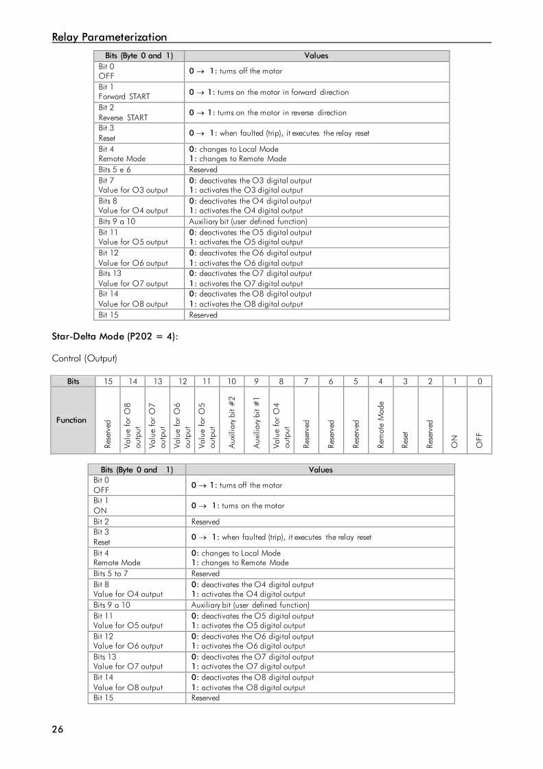
Bits (Byte 0 and 1) Values Bit 0 OFF
0 → 1: turns off the motor
Bit 1 Forward START 0 → 1: turns on the motor in forward direction
Bit 2 Reverse START
0 → 1: turns on the motor in reverse direction
Bit 3 Reset
0 → 1: when faulted (trip), it executes the relay reset
Bit 4 Remote Mode
0: changes to Local Mode 1: changes to Remote Mode
Bits 5 e 6 Reserved Bit 7 Value for O3 output
0: deactivates the O3 digital output 1: activates the O3 digital output
Bits 8 Value for O4 output
0: deactivates the O4 digital output 1: activates the O4 digital output
Bits 9 a 10 Auxiliary bit (user defined function) Bit 11 Value for O5 output
0: deactivates the O5 digital output 1: activates the O5 digital output
Bit 12 Value for O6 output
0: deactivates the O6 digital output 1: activates the O6 digital output
Bits 13 Value for O7 output
0: deactivates the O7 digital output 1: activates the O7 digital output
Bit 14 Value for O8 output
0: deactivates the O8 digital output 1: activates the O8 digital output
Bit 15 Reserved Star-Delta Mode (P202 = 4): Control (Output)
Bits 15 14 13 12 11 10 9 8 7 6 5 4 3 2 1 0
Function
Rese
rved
Valu
e fo
r O
8 ou
tput
Valu
e fo
r O
7 ou
tput
Valu
e fo
r O
6 ou
tput
Valu
e fo
r O
5 ou
tput
Aux
iliar
y bi
t #2
Aux
iliar
y bi
t #1
Valu
e fo
r O
4 ou
tput
Rese
rved
Rese
rved
Rese
rved
Rem
ote
Mod
e
Rese
t
Rese
rved
ON
OFF
Bits (Byte 0 and 1) Values
Bit 0 OFF
0 → 1: turns off the motor
Bit 1 ON
0 → 1: turns on the motor
Bit 2 Reserved Bit 3 Reset
0 → 1: when faulted (trip), it executes the relay reset
Bit 4 Remote Mode
0: changes to Local Mode 1: changes to Remote Mode
Bits 5 to 7 Reserved Bit 8 Value for O4 output
0: deactivates the O4 digital output 1: activates the O4 digital output
Bits 9 a 10 Auxiliary bit (user defined function) Bit 11 Value for O5 output
0: deactivates the O5 digital output 1: activates the O5 digital output
Bit 12 Value for O6 output
0: deactivates the O6 digital output 1: activates the O6 digital output
Bits 13 Value for O7 output
0: deactivates the O7 digital output 1: activates the O7 digital output
Bit 14 Value for O8 output
0: deactivates the O8 digital output 1: activates the O8 digital output
Bit 15 Reserved

Relay Parameterization
27
Dahlander Mode (P202 = 5): Control (Output)
Bits 15 14 13 12 11 10 9 8 7 6 5 4 3 2 1 0
Function
Rese
rved
Valu
e fo
r O
8 ou
tput
Valu
e fo
r O
7 ou
tput
Valu
e fo
r O
6 ou
tput
Valu
e fo
r O
5 ou
tput
Aux
iliar
y bi
t #2
Aux
iliar
y bi
t #1
Valu
e fo
r O
4 ou
tput
Rese
rved
Rese
rved
Rese
rved
Rem
ote
Mod
e
Rese
t
Low
spe
ed
STA
RT
Hig
h sp
eed
STA
RT
OFF
Bits (Byte 0 and 1) Values
Bit 0 OFF
0 → 1: turns off the motor
Bit 1 High speed START
0 → 1: turns on the motor with high speed
Bit 2 Low speed START
0 → 1: turns on the motor with low speed
Bit 3 Reset
0 → 1: when faulted (trip), it executes the relay reset
Bit 4 Remote Mode
0: changes to Local Mode 1: changes to Remote Mode
Bits 5 to 7 Reserved Bit 8 Value for O4 output
0: deactivates the O4 digital output 1: activates the O4 digital output
Bits 9 a 10 Auxiliary bit (user defined function) Bit 11 Value for O5 output
0: deactivates the O5 digital output 1: activates the O5 digital output
Bit 12 Value for O6 output
0: deactivates the O6 digital output 1: activates the O6 digital output
Bits 13 Value for O7 output
0: deactivates the O7 digital output 1: activates the O7 digital output
Bit 14 Value for O8 output
0: deactivates the O8 digital output 1: activates the O8 digital output
Bit 15 Reserved Pole-Changing Mode (P202 = 6): Control (Output)
Bits 15 14 13 12 11 10 9 8 7 6 5 4 3 2 1 0
Function
Rese
rved
Valu
e fo
r O
8 ou
tput
Valu
e fo
r O
7 ou
tput
Valu
e fo
r O
6 ou
tput
Valu
e fo
r O
5 ou
tput
Aux
iliar
y bi
t #2
Aux
iliar
y bi
t #1
Valu
e fo
r O
4 ou
tput
Rese
rved
Rese
rved
Rese
rved
Rem
ote
Mod
e
Rese
t
Low
spe
ed
STA
RT
Hig
h sp
eed
STA
RT
OFF
Bits (Byte 0 and 1) Values
Bit 0 OFF
0 → 1: turns off the motor
Bit 1 High speed START
0 → 1:: turns on the motor with high speed
Bit 2 Low speed START
0 → 1: turns on the motor with low speed
Bit 3 Reset
0 → 1: when faulted (trip), it executes the relay reset
Bit 4 Remote Mode
0: changes to Local Mode 1: changes to Remote Mode
Bits 5 to 7 Reserved

Relay Parameterization
28
Bit 8 Value for O4 output
0: deactivates the DO4 digital output 1: activates the DO4 digital output
Bits 9 a 10 Auxiliary bit (user defined function) Bit 11 Value for O5 output
0: deactivates the O5 digital output 1: activates the O5 digital output
Bit 12 Value for O6 output
0: deactivates the O6 digital output 1: activates the O6 digital output
Bits 13 Value for O7 output
0: deactivates the O7 digital output 1: activates the O7 digital output
Bit 14 Value for O8 output
0: deactivates the O8 digital output 1: activates the O8 digital output
Bit 15 Reserved
PLC Mode (P202 = 7): Control (Output)
Bits 15 14 13 12 11 10 9 8 7 6 5 4 3 2 1 0
Function
Rese
rved
Valu
e fo
r O
8 ou
tput
Valu
e fo
r O
7 ou
tput
Valu
e fo
r O
6 ou
tput
Valu
e fo
r O
5 ou
tput
Aux
iliar
y bi
t #2
Aux
iliar
y bi
t #1
Valu
e fo
r O
4 ou
tput
Valu
e fo
r O
3 ou
tput
Valu
e fo
r O
2 ou
tput
Valu
e fo
r O
1 ou
tput
Rem
ote
Mod
e
Rese
t
Rese
rved
Rese
rved
Rese
rved
Bits (Byte 0 and 1) Values
Bits 0 to 2 Reserved Bit 3 Reset
0 → 1: when faulted (trip), it executes the relay reset
Bit 4 Remote Mode
0: changes to Local Mode 1: changes to Remote Mode
Bits 5 Value for 01 output
0: deactivates the DO1 digital output 1: activates the DO1 digital output
Bits 6 Value for O2 output
0: deactivates the DO2 digital output 1: activates the DO2 digital output
Bit 7 Value for O3 output
0: deactivates the DO3 digital output 1: activates the DO3 digital output
Bit 8 Value for 04 output
0: deactivates the DO4 digital output 1: activates the DO4 digital output
Bits 9 a 10 Auxiliary bit (user defined function) Bit 11 Value for O5 output
0: deactivates the O5 digital output 1: activates the O5 digital output
Bit 12 Value for O6 output
0: deactivates the O6 digital output 1: activates the O6 digital output
Bits 13 Value for O7 output
0: deactivates the O7 digital output 1: activates the O7 digital output
Bit 14 Value for O8 output
0: deactivates the O8 digital output 1: activates the O8 digital output
Bit 15 Reserved
NOTE! Most of the bits of the command words above have a behavior similar to pushbuttons, i.e., only the 0 → 1 transition is important. Thus, the network planner must pay attention in order to write 0 in those bits again, after sending a valid transition command.

Relay Parameterization
29
P736 – Parameter Received at Word #2
P737 – Parameter Received at Word #3
P738 – Parameter Received at Word #4
Adjustable 0 to 899 Factory Setting: 0 Range:
Properties Sys, rw
Description: These parameters allow the user to program the writing of any other parameter of the equipment. In other words, it contains the number of another parameter whose content will be mapped at the network master output area. For instance, P736 = 163. In this case the content to be written in P163 (User Program Disabling) will be sent via the network. Thus, the network master memory position correspondent to the second writing word must contain the value for P163.
Function P734 option
Control Word #1 1 2
3 4
Parameter Received at Word #2 (content of the parameter programmed in P736)
Parameter Received at Word #3 (content of the parameter programmed in P737)
Parameter Received at Word #4 (content of the parameter programmed in P738)
P740 – Profibus DP Network Status
Adjustable 0 = Inactive Factory Setting: - Range: 1 = Profibus interface initialization error 2 = Offline 3 = Configuration data error 4 = Parameterization data error 5 = Clear mode 6 = Online
Properties RO
Description: It indicates the status of the Profibus network. The next table presents a brief description of these states.
Table 3.2 – Values for the parameter P740
State Description 0 = Inactive The Profibus interface is not installed in the SRW 01. 1 = Profibus interface initialization error
A problem during the Profibus interface initialization has been identified.
2 = Offline The Profibus interface is installed and correctly configured, but no data has been received from the network master.
3 = Configuration data error
Data received in the I/O configuration telegram are not in accordance with the SRW 01 configurations made through the parameters P728 and P734.
4 = Parameterization data error
Data received in the parameterization telegram do not have the correct format/values for the SRW 01.
5 = Clear mode During data exchange with the master, the relay received a command to enter the clear mode.
6 = Online I/O data exchange between the SRW 01 and the Profibus network master is being successfully executed.

Errors Related to the Profibus DP Communication
30
4 ERRORS RELATED TO THE PROFIBUS DP COMMUNICATION E0068 – Profibus DP Communication Timeout
Description: The SRW 01 has detected timeout in the communication with the Profibus network master. Actuation: If the Profibus network master is exchanging I/O data with the SRW 01 and the communication is interrupted, the SRW 01 can detect communication timeout3. In this case, offline communication will be signalized at the NET LED, the HMI (if installed) will show E0068, and the SRW 01 will execute the action programmed at the parameter P313. Possible Causes/Correction: Verify whether the network master is operating properly. Search for short-circuit or bad contact in the communication cables. Make sure the cables are not changed or inverted. Verify whether termination resistors with correct values were installed only at the extremes of the main bus. E0069 – Profibus Interface Initialization Error
Description: Profibus ASIC initialization error. Actuation: During the power-on, before allowing the communication with the master, the SRW 01 automatically executes an initialization procedure of the component responsible for the Profibus communication (ASIC). Incorrect installation of the communication module or hardware problems may prevent the proper execution of this procedure. In this case, initialization error will be signalized at the NET LED, the HMI (if installed) will show E0069, and the SRW 01 will execute the action programmed at the parameter P313. It is necessary to cycle the power of the relay in order to remove this error. Possible Causes/Correction: Verify the installation of the communication module. Cycle the power of the relay in order to repeat the initialization procedure. E0070 – Parameterization Data Error
Description: Data in the parameterization telegram received from the network master are invalid. Actuation: Before initiating the I/O data communication, the network master sends a telegram with the parameterization data for the network slave. In these data, information about the communication is included, as described by the GSD file. If there are invalid values in this telegram contents, the relay will indicate E0070 on the HMI (if installed), signalize this error at the NET LED and execute the action programmed at the parameter P313. Possible Causes/Correction: Verify the configurations made by the network master, for the communication with the relay. Verify if the GSD file registered for the relay is the one supplied with the product.
3 The time for timeout detection is normally automatically programmed by the network master during the parameterization telegram, before starting the data exchange with the SRW 01.
Errors Related to the Profibus DP Communication
31
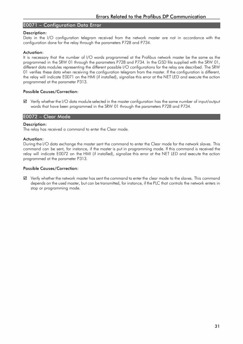
E0071 – Configuration Data Error
Description: Data in the I/O configuration telegram received from the network master are not in accordance with the configuration done for the relay through the parameters P728 and P734. Actuation: It is necessary that the number of I/O words programmed at the Profibus network master be the same as the programmed in the SRW 01 through the parameters P728 and P734. In the GSD file supplied with the SRW 01, different data modules representing the different possible I/O configurations for the relay are described. The SRW 01 verifies these data when receiving the configuration telegram from the master. If the configuration is different, the relay will indicate E0071 on the HMI (if installed), signalize this error at the NET LED and execute the action programmed at the parameter P313. Possible Causes/Correction: Verify whether the I/O data module selected in the master configuration has the same number of input/output
words that have been programmed in the SRW 01 through the parameters P728 and P734. E0072 – Clear Mode
Description: The relay has received a command to enter the Clear mode. Actuation: During the I/O data exchange the master sent the command to enter the Clear mode for the network slaves. This command can be sent, for instance, if the master is put in programming mode. If this command is received the relay will indicate E0072 on the HMI (if installed), signalize this error at the NET LED and execute the action programmed at the parameter P313. Possible Causes/Correction: Verify whether the network master has sent the command to enter the clear mode to the slaves. This command
depends on the used master, but can be transmitted, for instance, if the PLC that controls the network enters in stop or programming mode.