Smart Professional Surveillance System User’s Manual User's Manual V2.… · stream Right-click...
90
Smart Professional Surveillance System User’s Manual Version 2.00.0
Transcript of Smart Professional Surveillance System User’s Manual User's Manual V2.… · stream Right-click...

Smart Professional Surveillance System User’s Manual
Version 2.00.0

i
Table of Contents
1. OVERVIEW AND ENVIRONMENT..............................................................................1
1.1 Overview ............................................................................................................................. 1
1.2 SmartPSS Interface............................................................................................................. 1
2. LOGIN ...............................................................................................................................3
3. DEVICES ..........................................................................................................................5
3.1 Auto Search ........................................................................................................................ 5
3.2 Manually Add ...................................................................................................................... 6
3.3 Batch Import and Add Device ............................................................................................. 8
3.4 Modify IP ............................................................................................................................. 8
4. PREVIEW ...................................................................................................................... 11
4.1 Live ciew ........................................................................................................................... 11
4.2 E-Map................................................................................................................................ 16
4.2.1 New Map.................................................................................................................... 16
4.2.2 New Hot Zone ............................................................................................................ 18
4.3 Config IVS Channel........................................................................................................... 20
4.4 Smart Track Config (Fisheye+Dome) ................................................................................ 23
4.5 Smart Track Config (Dome+Fixed) .................................................................................... 25
4.6 PTZ ................................................................................................................................... 28
4.6.1 Preset ........................................................................................................................ 30
4.6.2 Tour ........................................................................................................................... 30
4.6.3 Scan .......................................................................................................................... 31
4.6.4 Pattern ....................................................................................................................... 31
4.7 Fisheye View Mode ........................................................................................................... 32
5. TOUR & TASK ............................................................................................................. 34
6. PLAYBACK .................................................................................................................. 38
6.1 Playback ........................................................................................................................... 38

ii
6.2 Playback Device Record ................................................................................................... 41
6.3 Export Device Record ....................................................................................................... 41
6.4 Playback Device Picture ................................................................................................... 43
6.5 Export Device Picture ....................................................................................................... 44
6.6 Playback Local Record ..................................................................................................... 44
6.7 Export Local Record ......................................................................................................... 45
6.8 Playback Local Picture ..................................................................................................... 47
7. LOG SEARCH .............................................................................................................. 49
7.1 Search Client Log ............................................................................................................. 49
7.2 Search Device Log ............................................................................................................ 49
8. SYSTEM CONFIG ....................................................................................................... 51
9. USER.............................................................................................................................. 54
9.1 Role Info ........................................................................................................................... 54
9.2 User .................................................................................................................................. 55
10. DEVICE CONFIG ..................................................................................................... 58
11. EVENT CONFIG....................................................................................................... 61
11.1 Event Type .................................................................................................................... 61
11.2 Event Alarm Link Config ............................................................................................... 63
11.2.1 Link Notice ................................................................................................................. 63
11.2.2 Link Video .................................................................................................................. 64
11.2.3 Link Alarm Output ....................................................................................................... 66
11.2.4 Arm Time ................................................................................................................... 67
11.3 Event View .................................................................................................................... 68
12. VIDEO WALL............................................................................................................ 69
12.1 Video Wall ..................................................................................................................... 69
12.2 Set Video Wall and Output ............................................................................................ 71
12.3 Scheme Tour on Video Wall.......................................................................................... 74

iii
12.4 Playback on Video Wall ................................................................................................ 76
13. PEOPLE COUNT ..................................................................................................... 77
14. HEAT MAP................................................................................................................ 80
15. PC-NVR ..................................................................................................................... 81
15.1 Disk Manager ................................................................................................................ 81
15.2 Channel Management ................................................................................................... 81
15.3 Set Record Plan ............................................................................................................ 82
15.4 Version Info .................................................................................................................. 83
15.5 Modify Port ................................................................................................................... 84
15.6 Modify Password .......................................................................................................... 85

iv
Welcome
Thank you for using our Smart Professional Surveillance System (SmartPSS)!
This user’s manual is designed to be a reference tool for operation of your system.
Here you can find detailed operation information about SmartPSS.

1
1. Overview and Environment
1.1 Overview
SmartPSS is an abbreviation for Smart Professional Surveillance System.
The software is to manage small quantity security surveillance devices. It releases with the
device and does not support the products from other manufacturers. It has the following features:
View real-time video of several camera channels.
View the playback video files from various cameras.
Support multiple scheduled arms to realize auto PC guard.
Support e-map; you can clearly view and manage all device locations.
Video wall preview.
People count and heat map.
Search and export log.
1.2 SmartPSS Interface
SmartPSS software interface includes 5 parts: function tab, system info, function list, shortcut,
and help. See Figure 1-1.
Figure 1-1
No. Name Note

2
1 Function tab Open function in New tab by clicking , you can open new
tab.
2 Help click ,switch user.
click ,lock screen
click ,go to config page
click ,get help document
click ,min page
click ,max page
click ,exit
3 System Info :show system time
click ,CPU occupancy and condition
4 Shortcut click ,quickly enter Event tab
5 Function list Include preview, playback, event, video wall, people count, log, event setup, device manager, device config, PC-NVR, tour plan, user and heat map.

3
2. Login
Background
For PC where SmartPSS is installed.
Item Requirements
OS Windows 7 and higher.
CPU Intel core i3 or higher.
Display card Intel HD Graphics and higher.
Memory 2GB or higher.
Displayer
Resolution
1024×768 or higher.
Steps
Step 1. Double click . See Figure 2-1.
Note:
Default username is admin, without password. Please set password at first time login.
Figure 2-1
Step 2. Enter username and password. Click login. See Figure 2-2.
Note:
When you check remember password, you do not need to enter password again at next
login. When you check both remember password and auto login, you can auto login at next
login.
After you add device, you can see homepage, see Figure 2-2.

4
Figure 2-2

5
3. Devices
Here you can add a single device or batch device via auto search. You also can config and
operate device.
3.1 Auto Search
Step 1. In Devices, click Search.
Step 2. Set device segment and click Search. See Figure 3-1.
Note:
Click Refresh, to refresh searched device.
Check IP of devoce
Check device IP you want to modify, click Modify IP to change IP. See Ch 3.4.
Figure 3-1
Step 3. Check device you want to add, click Add.
Step 4. Click OK. Login box pops up.
Step 5. Enter device username and password. Click OK. After you add device, click Cancel, so
system shows device list added. See Figure 3-2.
After device is added, you can view device name, IP/domain, type, model, port, channel
number, online status, SN and operate device.
After device is added, in Devices it auto shows device type tab, you can view added device
here.
For different devices, please note that interface subject to actual interface.
Click of device, to modify device info.
Click of device, to go to device config page.
Click of device to exit device. When icon changes to , click again to re-login.

6
Check device you want to delete, click Delete to batch delete them. Click of device to
delete one by one.
Check device you want to export and click Export.
When show device code is selected in system setup, device is shown with . You
can click it to customize device code. This is mainly used for operation via keyboard.
Figure 3-2
3.2 Manually Add
Step 1. In Devices interface, click Add, see Figure 3-3.

7
Figure 3-3
Step 2. Set device parameter, see the following chart.
Item Function
Device name Please input a device name here.
Method to
add By IP/domain and SN.
IP/Domain name
Device IP address or domain name.
Note:
You can add device of IPV6 address.
SN
Device SN.
Note:
For P2P device only.
Port Device IP port.
It is 37777 by default.
Group Name You can choose one group.
User name The user name you login the device.
Password The password you login the device.
Step 3. Click Add, complete adding of device. Click Save and Continue to add more devices.

8
3.3 Batch Import and Add Device
Before you batch import device, you shall get device info. You can export device info to get
device info file.
Step 1. In Devices, click Import. See Figure 3-4.
Figure 3-4
Step 2. According to actual condition, select import method.
Select Local tab to select device info locally.
Select From www.easy4ip.com, enter username and password.
Step 3. Click Import. When successfully imported device, system shows a message, click OK.
3.4 Modify IP
Step 1. In Devices interface, click Search.
Step 2. Set device segment and click Search. See Figure 3-5.

9
Figure 3-5
Step 3. Check device you want to modify IP, click Modify IP.
Step 4. Enter username and password. Click OK.
When you check a single device, system pops u p Modify IP box, see Figure 3-6.
Figure 3-6
When select more then one device, system pops up Batch Modify IP box, see Figure 3-7.

10
Figure 3-7
Step 5. Set device new IP start IP, subnet mask and gateway.
Step 6. Click Save.

11
4. Preview
4.1 Live ciew
You can live view video, local record, snapshot, enable audio, talk, instant playback, zoom in
video, switch stream, config device parameter, config intelligent channel, config master -slave
track, update channel info and etc.
In New tab, click Live View, see Figure 4-1.
Figure 4-1
No.
Task Note
1 Device list
You can switch streams, create device groups, create new maps, update channel information, modify channel names, log off, and log in to devices.
When the Default Device Tree is set to Device Tree (by device), the device tree displays the grouping and channels for the device.
When the Default Device Tree is set to Area Tree (by channel), the device tree displays the zones and channels.

12
No.
Task Note
Switch
stream
Right -click the group / device or area, and select the main stream or sub stream. The video window will display the
preview interface of all channels in the group / device or area in the main stream or auxiliary stream.
Note: When the number of video windows is less than the number of
channels on the device, the video window displays the preview interface for all channels in a split screen.
Right -click the channel, select the main stream or sub
stream, the video window will be the main stream or sub stream shows the preview interface of the channel.
Select the video window in which the preview is enabled, right-click to select Stream Type> Main Stream, Stream Type> Sub Stream 1 or Stream Type> Sub Stream 2.
Note:
You can preview both the main stream and secondary streams simultaneously on the same channel.
New device
group
When the Default Device Tree is set to Device Tree (by device),
right-click the group in the Organizational Tree, select New Group, set the group name in the New Group box, Click Save to create a device grouping.
Note:
If you need to continuously create multiple groups, set group
name, and click 'Save and Continue. You can right-click the new group, to rename or delete the
group. You can only delete groups without devices.
New e-map
When the Default Device Tree is set to Device Tree (by device), right-click the group in the Organization Tree area and select
New Map to create a new E-Map. Once the map has been added, you can edit, rename, and delete the map or hotspot by right -clicking on the map or heat
map. E-map can be displayed directly in the list of previewed devices, you can drag the map directly to the preview window to preview,
you can save the map to view, easy to open the next time. For details on how to create a new map, see Ch 4.2.
Create
zone
When the Default Device Tree is set to Zone Tree (by channel),
right-click the area in the Area Tree area, select New Zone, set the name in the New Zone dialog box, Click Save to create the area.
Note:
If you need to continuously create multiple zones, set
the name, click Save and Continue.
You can right-click the new zone, to rename or delete the zone.
You can only delete groups without devices.

13
No.
Task Note
Device
config
When the Default Device Tree is set to Device Tree (by device), right-click the device and choose Device Configuration from the
shortcut menu. The Device Configuration page appears. For details about how to configure a device, see section Ch 10. The parameters of different devices may be different. For the
configuration of the parameters, refer to the corresponding device manual.
Zero
Channel
Preview
When the Default Device Tree is set to Device Tree (by device),
right-click the NVR device and select Zero Channel Preview.
Channel
display
When the Default Device Tree is set to Device Tree (by device), right-click the storage device and choose Channel Display>
Show Binding Channels or Show All Channels to switch the channel display mode.
Modify
channel
name
When the Default Device Tree is set to Device Tree (by device), right-click the device channel under the storage device and select Modify Channel Name.
IVS
channel
config
When the Default Device Tree is set to Device Tree (by device), right-click the device and choose IVS Channel Cfg to jump to the IVS Channel Cfg interface.
See Ch 4.4.
Alarm
output
When the Default Device Tree is set to Device Tree (by device), right-click the device and select Alarm Output to turn on or off
the alarm output channel.
Configure
the smart
track
Right -click the device, select Smart track configuration, jump to smart track configuration interface. See Ch 4.4.
Configure
the master-
slave track
Right -click the device and select Master-slave Track Configuration jump to Master-slave Track Configuration interface.
See Ch 4.5.
Update
channel
information
/ name
When the Default Device Tree is set to Device Tree (by device), right-click the device and select Update Channel Info to update the channel name or channel number changes.
When the Default Device Tree is set to Area Tree (Per Channel), right-click the device and select Update Channel Name to update the channel name.
Logout and
login
When the Default Device Tree is set to Device Tree (by device),
right-click the device and select Logout. The software and device are disconnected. After logging out, right-click the device, select Login, reconnect device.
View When next to View , Open the view interface.
You can create view group, modify view name, move view group, delete views, and playback view record on the view interface.
New view
group
When next to View. Open the view interface. Click New Group, set the group name in the New Group dialog box and click Save to create the view group.
If you need to continuously create multiple groups, set group name, and click 'Save and Continue.
You can right-click the new group, rename or delete the
group. You can only delete groups that have no views.

14
No.
Task Note
Modify view
name
When next to View. Open the view interface.
Right-click the view name and select Modify View Name.
Delete view When next to View. Open the view interface.
Right-click the view name and select Delete This Item.
Move view
group
When next to View. Open the view interface.
Right -click the view name, select Move View Grouping and select the group you want to move to.
Playback
view record
When next to View. Open the view interface.
Right -click the view name and select Playback to enter the playback interface. See Ch 6.
PTZ
For motorized zoom devices, focus, autofocus, or focus can be reset.
For PTZ setting, you can simulate the mouse, open or close PTZ menu, adjust PTZ speed, direction, zoom, focus and iris.
Click More Features to set Preset, Tour, Horizontal Rotation, Scan, Track, and Accessibility. See Ch 4.6.
2
View real-
time stream
info
Select a open live window, the status bar displays real-time
information stream.
Local record
Select open video window which is ON, and click or right click
to select Start Record.
Note: You can modify the saved path in System Configuration> File Settings .
Snapshot
Select open video window which is ON, and click or right-click
to select Snapshot, snapshot a single picture. Note: You can change the path where the image is saved in System
Configuration> File Settings .
Triple
Snapshot
Select the preview video window, right click Triple Snapshot, the system continuously snapshot three pictures.
Start audio Select open video window which is ON, and click or right-click to select Start Audio.
Start talk Select open video window which is ON, and click or right-click
to select Start Talk, you can talk between the client and the device.
Turn on the
remote
intercom
When you preview the channel under the storage device, and
the device supports remote channel intercom, select the video
window with preview opened, right -click to select Turn on the
remote intercom, the remote channel on the client and the
storage device can be speak.

15
No.
Task Note
Start instant
playback Select open video window which is ON, and click or right-click
to select Start Instant Playback .
Zoom in Select open video window which is ON, and click .
Close
window Select open video window which is ON, and click or right click
to select Close Window .
Close all
windows
Select the video window, right-click to select Close All Windows .
3
Live
preview
Double-click a device in the Organization Tree or drag the device
to the video window for a live preview.
Playback Select the preview video window, right-click Playback to enter the Playback interface. See Ch 6.
Fisheye
installation
For fisheye device only.
Select the video window with preview ON, right click on Fisheye
Installation Mode and select the installation mode according to the
actual installation of the device.
Fisheye installation mode includes (Ceiling), (Wall
mount) and (GND).
Fisheye
view mode
For fisheye device only.
Select the preview video window, right -click the Fisheye view
mode, according to the actual situation to select the desired view
mode.
The view mode is different depending on the installation mode of
the fisheye. See Ch 4.7.
Split screen
tracking
Split screen tracking includes the normal mode, 1 +3 mode and
1 +5 mode three modes.
Normal mode: Original image.
1 + 3 mode: the original image and 3 sub-window, the original image can be adjusted 3 sub-window position.
1 + 5 mode: the original image and 5 sub-window, the original image can be adjusted 5 sub-window position.
Adjust
It is used to adjust the preview effect of the video screen on the
client and does not change the actual image parameters of the
device.
You can adjust the brightness, contrast, saturation and hue of
the video screen.

16
No.
Task Note
Smart
overlay
Make intelligent rules or intelligent object box displayed in the
video screen.
Select the video window with the preview turned on, right -click
on the Intelligent overlay> Intelligent rule or Intelligent object
box.
4
Save view
Click , Save the current preview video window as a view,
and you can view it instantly in the Preview, Playback, Tour interface.
After creating the round-robin schedule, click , Check the
Save to Tour Plan, you can also save the view to the tour plan.
See Ch 5.
Tour ON After creating a tour plan, in shown tour plan, you
can select tour plan and click to enable tour.
See Ch 5.
5
Set video
scale
You can set the video aspect ratio in two ways.
Select the video window, right-click to select Window Scale,
select the video screen display ratio.
In Select video screen display ratio.
Set video
window
display mode
Click In the icon, the video window is set to
the corresponding number of windows display mode.
Click , In the pop-up interface customize the video
window display mode. In the standard interface split area, select the video
window display mode, click at the upper right corner of
the display, The latest collection of three video window
display mode is displayed in the preview interface on the toolbar.
In the Custom Split area, click , Custom video
window display mode.
Click or select the video window, right select full screen, video window full screen display.
4.2 E-Map
Via E-map you can straightly known the location of video channel or alarm channel and live
preview.
4.2.1 New Map
Step 1. Right click group in Organization Tree, select New Map. See Figure 4-2.

17
Figure 4-2
Step 2. Set map name, select path of picture.
Step 3. Click Save. See Figure 4-3.
Note:
Click , create new hot zone on map, see Ch 4.2.2.
Click , modify map name or replace map.
Click to adjust opacity.
At the lower right corner, you can see aerial view of map. Click , to close aerial view and
click to open aerial view.

18
Figure 4-3
Step 4. Drag camera to corresponding monitor position on map to adjust camera monitor range,
or drag camera alarm input into map.
Step 5. Click to save map.
Step 6. View device live preview on map.
a) Open Live interface, in device list double click heat map or drag heat map into preview
window.
b) On map click camera or place mouse on camera for a few seconds, in the pop-up
window you can view live preview.
Note:
Click map preview window, right click and select Open All Channels, at bottom of
preview window it shows live of all devices.
Click preview window on map, right click Video Wall, and in pop-up window it
shows live of all devices.
4.2.2 New Hot Zone
For hot zone, you can add corresponding picture on map.
Step 1. In e-map interface, click . See Figure 4-4.

19
Figure 4-4
Step 2. Set map name, select picture path.
Step 3. Click Save. See Figure 4-5.
Note:
Click to create new zone.
Click to modify heat map name or replace heat map.
Click to modify heat map name or replace heat map.
Click to adjust camera monitor range opacity.
At the lower right corner, you can see aerial view of heat map. Click , to close aerial view
and click to open aerial view.
At the lower left corner, click picture window to return to previous heat zone or map.

20
Figure 4-5
Step 4. Double click heat map, drag camera to corresponding monitor position on map to adjust
camera monitor range.
Step 5. Click to save heat map.
Step 6. View device live preview on map.
c) Open Live interface, in device list double click heat map or drag heat map into preview
window.
Note:
In heat map preview window status bar, click to return to map preview.
d) On map click camera or place mouse on camera for a few seconds, in the pop-up
window you can view live preview.
Note:
Click map preview window, right click and select Open All Channels, at bottom of
preview window it shows live of all devices.
Click preview window on map, right click Video Wall, and in pop-up window it
shows live of all devices.
4.3 Config IVS Channel
By setting IVS channel, you can mark depth of field of IVS plan. Different cameras support
different IVS plan, subject to actual interface.
21
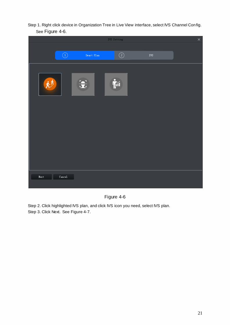
Step 1. Right click device in Organization Tree in Live View interface, select IVS Channel Con fig.
See Figure 4-6.
Figure 4-6
Step 2. Click highlighted IVS plan, and click IVS icon you need, select IVS plan.
Step 3. Click Next. See Figure 4-7.

22
Figure 4-7
Step 4. Mark depth of field.
a) Click the mark area in the video window to draw the mark area, right-click to draw after
drawing to complete.
At least 3 points are required to draw in the mark area.
b) Set the length of the vertical ruler, click , draw vertical ruler in the mark area, left-click
to complete the drawing.
Repeat this step to add 3 vertical rulers to the mark area.
c) Set the length of the horizontal ruler, click , and draw a horizontal ruler in the mark
area, left-click to complete the drawing.
Note:
Select vertical or horizontal ruler, click Re-draw, re-draw the ruler, select the calibration area,
click Redraw, redraw the calibration area, the vertical scale and the horizontal ruler.
Select the vertical or horizontal ruler, click Delete, delete the ruler; Select the calibration area,
click Delete, delete the calibration area, vertical ruler and horizontal ruler.
Step 5. (Optional) Measure distance vertically or horizontally.
Note:
23
When you need to measure, you need to follow this step.
a) Click Apply, to save marked depth of field.
b) Measure distance.
Click vertical distance, and mark vertical line in marked area, system shows drawn
vertical length.
Click horizontal distance, and mark horizontal line in marked area, system shows
drawn horizontal length.
Step 6. Click Save.
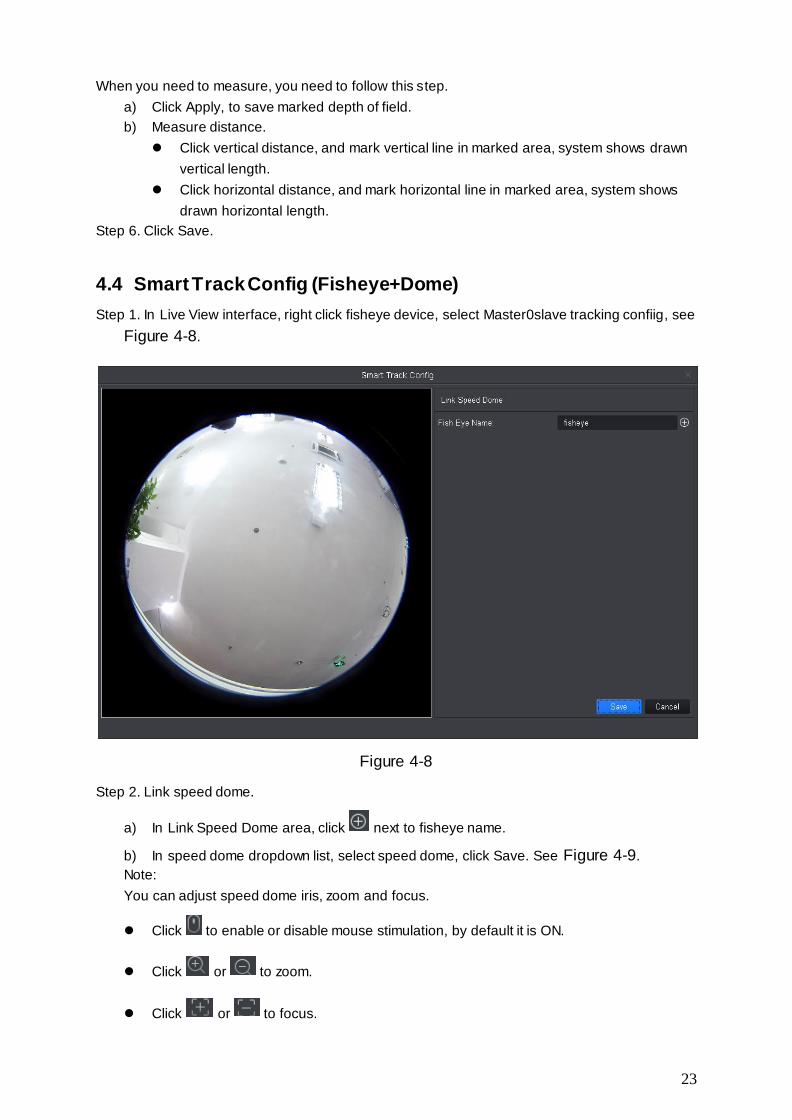
4.4 Smart Track Config (Fisheye+Dome)
Step 1. In Live View interface, right click fisheye device, select Master0slave tracking confiig, see
Figure 4-8.
Figure 4-8
Step 2. Link speed dome.
a) In Link Speed Dome area, click next to fisheye name.
b) In speed dome dropdown list, select speed dome, click Save. See Figure 4-9.
Note:
You can adjust speed dome iris, zoom and focus.
Click to enable or disable mouse stimulation, by default it is ON.
Click or to zoom.
Click or to focus.

24
Click or to adjust iris.
Click to draw a box via mouse on the monitor video, and speed dome will rotate
and focus to this scene quickly,
and cannot be enabled at the same time.
Figure 4-9
Step 3. Add mark point.
a) Click Add, in fisheye live preview interface shows mark box. Drag mark box to suitable
position.
b) Be default, to enable mouse stimulation, use mouse to drag speed dome video to
suitable position.
c) In mark point list, click of corresponding mark point, save.
Repeat step 1 to 2 to add at least three mark points.
Step 4. Click OK.
Step 5. View smart track.
a) Right click the fisheye device, select master-slave tracking.
See Figure 4-10.
Link mode is enabled by default, click to correct fisheye mode and switch link mode.
Enable fisheye correction, and in fisheye preview window, right click and select fisheye
installation method and view mode. See Ch 4.7.
On the left you can set PTZ, see Ch 4.6.

25
Figure 4-10
b) In fisheye device preview interface click any spot, speed dome on the right auto links to
the corresponding position.
4.5 Smart Track Config (Dome+Fixed)
After you have configured dome and fixed camera linkage, when intelligent rule of fixed camera
triggers alarm, speed dome auto links to corresponding position and tracks object until the object
exceeds monitor range or tracking time limit.
Condition
Fixed camera has set trip wire, zone, loitering or fast move intelligent rule.
Steps
Step 1. In Organization Tree of preview interface, right click fixed camera, select Master -slave
tracking config, see Figure 4-11.

26
Figure 4-11
Step 2. Link speed dome.
a) In Link Speed Dome area, right click host name.
b) In dropdown list, select speed dome.
c) Config track parameter, see
Parameter Note
Expected zoom Zoon ratio when link to speed dome tracking
Horizontal zoom
angle Horizontal zoom ratio when link to speed dome tracking
Vertical zoom angle Vertical zoom ratio when link to speed dome tracking
Track length Time length of speed dome
Idle length Check Enable, to enable idle length, when speed dome no tracking time exceed set idle time, speed dome will rotate to corresponding position as set.
d) Click Save. See Figure 4-12.
Note:
You can adjust speed dome iris size, zoom and focus.
Click , enable to disable mouse stimulation, by default is in enabled.
Click or to zoom.
Click or to focus.
Click or to adjust iris.
Click to draw a box via mouse in monitor video, speed dome will quickly position to it.
and cannot be enabled at the same time.

27
Figure 4-12
Step 3. Add mark point.
Step 4. Add mark point.
a) Click Add, in fixed camera live preview interface shows mark box. Drag mark box to
suitable position.
b) Be default, to enable mouse stimulation, use mouse to drag speed dome video to
suitable position.
c) In mark point list, click of corresponding mark point, save.
Note:
Click Clear to delete all mark points.
Repeat step1 to 3 to add at least four mark points.
d) (Optional) you can select preset in Preset.
When speed dome tracking time exceed set idle time, speed dome will rotate to
corresponding position.
Note:
When idle length is enabled, need to run this step.
Step 5. Click OK.
Step 6. View smart track.
a) Right click the fixed camera device, select master-slave tracking.
See Figure 4-13.
Link mode is enabled by default, click to disable auto tracking.
On the left you can set PTZ, see Ch 4.6.
Figure 4-13
b) When fixed camera preview interface intelligent rule triggers alarm, speed dome on the
right auto link to corresponding position and track object until the object exceeds
monitor range or exceed tracking length.

28
4.6 PTZ
Different device PTZ have different setup interface, subject to actual condition.
See the following figures and charts.
Figure 4-14
Figure 4-15
Parameter Note
Zoom Click or to adjust zoom.
Switch to PTZ Click Switch to PTZ, system jumps to PTZ control.
Focus Click or to adjust definition.
Auto Focus Click Auto Focus to auto focus.
Reset Focus Click Reset Focus to reset.

29
Figure 4-16
Parameter Note
Menu Click go to PTZ menu.
Mouse stimulation Click , via mouse operate PTZ.
Direction Set PTZ direction in 8 directions.
3D position Click , and draw a box in video monitoring, PTZ will rotate
and focus to this scene.
Step Control PTZ rotation speed, can be set 1 to 8 different rotation
step.
Zoom Click or to adjust zoom.
Focus Click or to adjust definition.
Iris Click or to adjust brightness.
Preset
By setting the Preset, you can quickly go to the preset
position corresponding to the camera. Preset setting For
details, see Ch 4.6.1.
Note:
You can set up to 128 presets.
Tour
By setting Cruise, the camera can cruise between different
preset points. Cruise setting details, see Ch 4.6.2 . Note:
You can set up to eight cruise group.

30
Parameter Note
Horizontal rotation
By setting Horizontal rotation, the camera can be rotated
horizontally.
in , Select Horizontal rotation
and click , turn on horizontal rotation.
Scan
By setting the two borders, the camera rotates repeatedly
between the two borders. Scan settings For details, see Ch
4.6.3.
Pattern
By setting the Tour track, the user operation during the rotation
of the camera recorded, the camera can be rotated according to
the track record. Patrol track setting details, see Ch 4.6.4.
AUX With aux, aux commands can be entered to turn on the aux
points.
4.6.1 Preset
By setting the preset point, you can quickly go to the preset position corresponding to the camera.
Step 1. Via PTZ direction control the camera to designated position.
Step 2. In select preset, click .
Step 3. In select preset no., enter preset name.
Step 4. Click to save preset.
Step 5. Click to delete non-necessary preset.
Step 6. Select preset and click , camera rotates to corresponding position.
4.6.2 Tour
By setting the tour, the camera can tour between the different preset points.
Warning:
Set at least two presets before you can tour.
Step 1. In , select tour, and click . See Figure 4-17.

31
Figure 4-17
Step 2. Set tour no. and tour name.
Step 3. Select preset.
a) In Preset list select preset, and enter time.
b) Click to add preset.
Repeat this step to add more presets.
Step 4. Click OK.
Step 5. You need to select tour no., click so camera will tour among different presets.
4.6.3 Scan
By setting the two borders, the camera rotates repeatedly between the two borders.
Step 1. In select Scan.
Step 2. By control PTZ direction, rotate PTZ to designated left position, click to set left border.
Step 3. By control PTZ direction, rotate PTZ to designated right position, click to set right
border.
Step 4. Click to repeat rotation among two borders.
4.6.4 Pattern
Record down camera rotation process, via pattern rotation function.

32
Step 1. In select Pattern.
Step 2. Click to start to set pattern, and zoom, focus or rotate camera.
Step 3. Click to complete.
Step 4. Select pattern no., click , camera rotate pattern according to record.
4.7 Fisheye View Mode
Only fisheye device supports installation and view mode, different installation modes
corresponding to view mode referring to the following chart.
parameter Description
View mode
Current video screen (by default support the original image mode), in accordance with the different installation methods, with other different presentation as follows:
Ceiling: 1P + 1, 2P, 1 +2, 1 +3, 1 +4, 1P +6, 1 +8.
Wall mount: 1P, 1P + 3, 1P + 4, 1P + 8.
GND: 1P +1,2 P, 1 +3, 1 +4, 1P +6, 1 +8.
Note:
When switching installation mode, by default show the original image mode.
Ceiling/wall
mount/GND original image
That is the original image has not been corrected.
Ceiling 1 + 2
That is the original image plus two independent videos and
the original image sub-frame support zoom, move.
Ceiling /
wall mount
1P + 1
Expand the rectangle that is 360 ° panoramic + independent sprite and rectangular expansion panorama sub image support zoom, move operation, expand the rectangle star ting about Panorama also supports the move operation.
2P
That is 180 ° rectangular two associated expanded screen,
any time two sub-windows are composed of 360 ° panorama, also known as double Panorama, two rectangular stretches the picture support and move around the starting point of the operation, and mutual interaction.
1 + 3
That is the original image +3 independent videos and the
original image sub-frame support zoom, move.
1 + 4
That is the original image +4 independent videos and the original image sub-frame support zoom, move operation, the original image also supports changing the rotation starting operation.
1P + 6
This is rectangle that is 360 ° panoramic +6 independent
videos and rectangular expansion panorama sub frame support zoom, move operation, expand the rectangle starting

33
about Panorama also supports the move operation.
1 + 8
That is the original image +8 independent videos and the original image sub-frame support zoom, move.
Wall mount
1P
That rectangle from left to right 360 ° panorama unfold, 180 °
panoramic rectangular expand operations to support moves up and down to change the vertical viewing angle.
1P + 3
Expand the rectangle that is 360 ° panoramic +3 independent videos and rectangular expansion panorama sub frame support zoom, move operation, rectangular panoramic expand support moves up and down operation, change the vertical viewing angle.
1P + 4
Expand the rectangle that is 360 ° panoramic +4independent
video and rectangular expansion panorama sub frame support zoom, move operation, rectangular panoramic expand support moves up and down operation, change the vertical viewing angle.
1P + 8
Expand the rectangle that is 360 ° panoramic +8 independent videos and rectangular expansion panorama sub frame support zoom, move operation, rectangular panoramic expand support moves up and down operation, change the vertical viewing angle.

34
5. Tour & Task
By setting tour plan, you can tour each window.
Step 1. In New function tab, click Tour & Task.
Step 2. Add tour plan.
a) Click Add. See Figure 5-1.
Figure 5-1
b) Double click tour plan name or click to modify tour plan name.
Step 3. Set task.
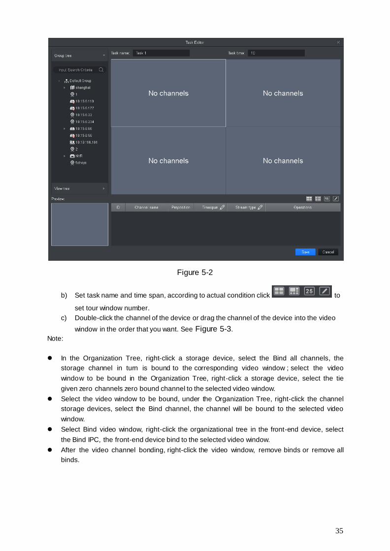
a) Click . See Figure 5-2.
35
Figure 5-2
b) Set task name and time span, according to actual condition click to
set tour window number.
c) Double-click the channel of the device or drag the channel of the device into the video
window in the order that you want. See Figure 5-3.
Note:
In the Organization Tree, right-click a storage device, select the Bind all channels, the
storage channel in turn is bound to the corresponding video window ; select the video
window to be bound in the Organization Tree, right-click a storage device, select the tie
given zero channels zero bound channel to the selected video window.
Select the video window to be bound, under the Organization Tree, right-click the channel
storage devices, select the Bind channel, the channel will be bound to the selected video
window.
Select Bind video window, right-click the organizational tree in the front-end device, select
the Bind IPC, the front-end device bind to the selected video window.
After the video channel bonding, right-click the video window, remove binds or remove all
binds.

36
Figure 5-3
d) Set channel preset, time span, stream type and channel sequence.
Note:
Click of the corresponding channel, in the left preview screen to display live
preview or e-map information.
Click or of the corresponding channel, adjust the channel sequence in the
task.
Click of the corresponding channel, delete the corresponding channel.
e) Click Save, See Figure 5-4.

37
Figure 5-4
Step 4. Enable tour task.
a) In New function tab, click Preview.
b) Click tour plan below.
c) Click to run the plan.

38
6. Playback
6.1 Playback
You can playback and export device record, device picture, local record and local picture.
In New tab, select Playback, see Figure 6-1.
Figure 6-1
No. Task Note
1
Playback
video
You can play back the recording device. For details, see Ch 6.2.
Playback
image You can picture playback device. For details, see Ch 6.4.
Playback
local video
You can play back the local video. For details, see For details, see Ch 6.6.
Playback
local picture
You can play back the local picture. For details, see For details, see Ch 6.8.
Organization
Tree / Area
Tree
When the Default Device Tree is set to Device Tree (by device), the device tree displays the grouping and channels
for the device. When a default device tree is set to Area Tree (by channel),
the device tree display channel.

39
Default Device Tree setting, see Ch 8.
Logout and
login
When the Default Device Tree is set to Device Tree (by device), right-click the device and select Logout. The software and
device are disconnected. After logging out, right-click the device, select Login, reconnect device.
View
In the Device tab, click behind View . Open View interface,
playback view video device. For details, refer to Ch 4.1.
2
View
playback
stream
information
Choose video window with open video, in status bar it displays
the playback stream information.
Snapshot
Select open video window, click or right-click to select
Snapshot, Snapshot a single picture.
You can click in the homepage, modify the path to save the
picture.
Zoom Select open playback video window, click .
Close
window
Select Open playback video window, click or right click to
select Close Window .
Close all
windows Select the video window, right-click to select Close all windows .
3
Set aspect
ratio
Select the video window, right-select Window Scale, select the
video aspect ratio.
Enable Audio
You can turn on the audio through the following two ways.
Select open playback video window, right-select Audio.
Playback control toolbar at the click , and adjust the volume.
4
Set the
device
record
search
criteria
In the Devices tab, select the device or view, select Record, set the record type, stream, start time and end time, click Search, the recording information is displayed in the schedule box.
Record type includes all types of video record, general
record, alarm record, motion detection record, intelligent record and card record.
Stream includes main stream and sub stream. Interval of start time and end time must be within a day.
Set the
device
picture
search
criteria
In the Devices tab, select the device, or view, select Picture, set the start time and end time, click Search, image information is displayed in the playback window. Interval of start time and end time must be within a day.
5 Time Show existing video display information.

40
progress bar
6
View
progress bar Click to view the video or image export progress and
export results.
Export
record Export device video files, see Ch 6.3.
Export
picture Export device picture files, see Ch 6.5.
Export local
record Export local video files. See Ch 6.7.
Open Video In the Local>
Smart search
Select open playback video window, click , in the video
playback window, select the smart search, click device
again. The software will search for the video motion detection,
click to exit the smart search.
7
Playback
control
toolbar
Control video playback and audio.
Video playback from the same point in time for all channels.
Reverse video playback.
Start video playback.
Pause video playback.
Stop video playback.
Single frame backward playback.
Single-frame forward playback.
Adjust the playback speed.
8
Set the video
window
display mode
In select the desired video window
display mode or select to customize video window
display mode.
Click or select the video window, right select full screen, video window full screen display.
9 Video file list
Click the icon to expand the list of the corresponding channel video file, you can select video files for playback and export the corresponding video file.

41
6.2 Playback Device Record
Condition
There is device record inside channel.
Steps:
Step 1. In playback interface, click Device tab.
Step 2. In Organization Tree, select device channel or select view in View.
Step 3. Select record and set record search criteria.
a) Select record type and stream, and set time.
b) Click Search.
Step 4. Select window with record, click .
See Figure 6-2.
Figure 6-2
6.3 Export Device Record
Condition
There is device record inside channel.
Steps:
Step 1. In playback interface, click Device tab.
Step 2. In Organization Tree, select device channel or select view in View.
Step 3. Set record search criteria.
a) Select record type and stream, and set time.
b) Click Search.
42
Step 4. Select window with record, click .
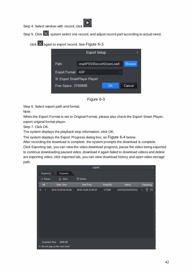
Step 5. Click , system select one record, and adjust record part according to actual need,
click again to export record. See Figure 6-3.
Figure 6-3
Step 6. Select export path and format.
Note:
When the Export Format is set to Original Format, please also check the Export Smart Player,
export original format player.
Step 7. Click OK.
The system displays the playback stop information, click OK.
The system displays the Export Progress dialog box, as Figure 6-4 below.
After recording the download is complete, the system prompts the download is complete.
Click Exporting tab, you can view the video download progress, pause the video being exported
to continue downloading paused video, download it again failed to download videos and delete
are exporting video; click exported tab, you can view download history and open video storage
path.

43
Figure 6-4
6.4 Playback Device Picture
Condition
There is device picture inside channel.
Steps
Step 1. In Playback interface, select Device tab.
Step 2. In Organization Tree, select device channel or in View select view.
Step 3. Select picture and set time. See Figure 6-5.
Click on the right, you can open and close device picture list.
In device picture list, click , device picture list will be shown in format of list; click , device
picture list is shown in format of thumbnail.
Figure 6-5
Step 4. Playback picture.
Manual playback: Click Next or Preview.
Auto playback: Slide to auto play, and set interval, system will auto playback
local picture.

44
6.5 Export Device Picture
Step 1. In Playback interface, select Device tab.
Step 2. In Organization Tree select device channel or in View select view.
Step 3. Select Picture and set time.
Step 4. Click on the right, to export device picture.
Step 5. Click . See Figure 6-6.
Figure 6-6
Step 6. Select export path, click OK. See Figure 6-7.
Click Exported tab, you can view download record, open picture storage path and delete
downloaded file.
Figure 6-7
6.6 Playback Local Record

45
Condition
There is local record in the channel, see Ch 4.1.
Steps
Step 1. In Playback interface, select Local tab.
Step 2. Click Record tab.
System shows local record list.
In local record list, click , display in list mode. Click , display in thumbnail mode.
Step 3. Select record to playback, click or double click record.
See Figure 6-8.
Note:
You can click to open local record file for playback.
Figure 6-8
6.7 Export Local Record
You can export local record.
Condition
There is local record in this channel, see Ch 4.1.
46
Steps
Step 1. In Playback interface, click Local tab.
Step 2. Click Record tab.
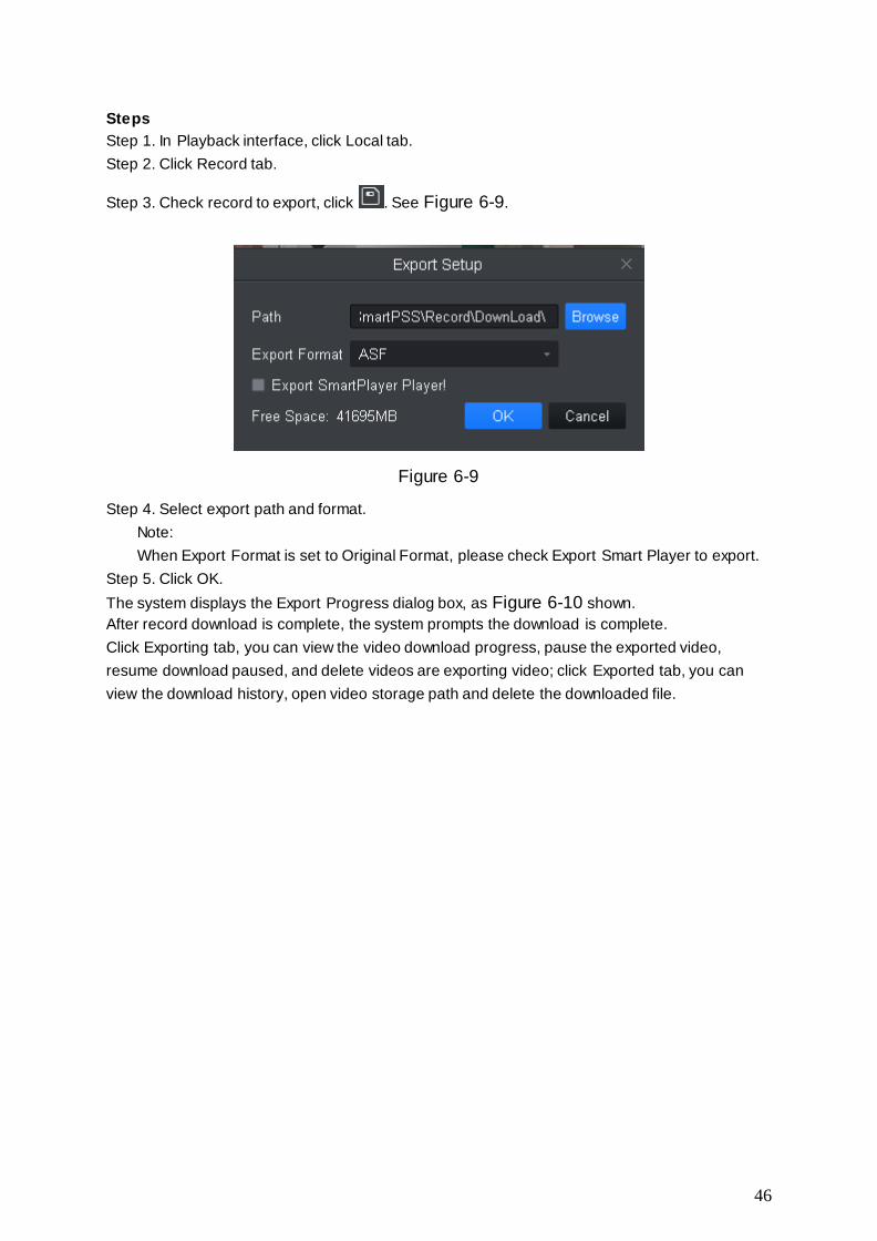
Step 3. Check record to export, click . See Figure 6-9.
Figure 6-9
Step 4. Select export path and format.
Note:
When Export Format is set to Original Format, please check Export Smart Player to export.
Step 5. Click OK.
The system displays the Export Progress dialog box, as Figure 6-10 shown.
After record download is complete, the system prompts the download is complete.
Click Exporting tab, you can view the video download progress, pause the exported video,
resume download paused, and delete videos are exporting video; click Exported tab, you can
view the download history, open video storage path and delete the downloaded file.

47
Figure 6-10
6.8 Playback Local Picture
Condition
There is local picture in the channel, see Ch 4.1.
Steps
Step 1. In Playback interface, select Local tab.
Step 2. Click Picture tab.
System shows local record list.
In local picture list, click , display in list mode. Click , display in thumbnail mode.
Step 3. Select picture to playback, click or double click picture
See Figure 6-11.
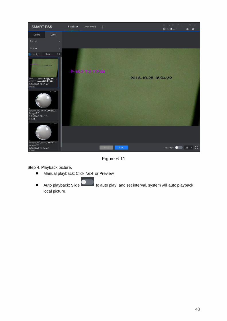
48
Figure 6-11
Step 4. Playback picture.
Manual playback: Click Next or Preview.
Auto playback: Slide to auto play, and set interval, system will auto playback
local picture.

49
7. Log Search
7.1 Search Client Log
Step 1. In New tab, click Log.
Step 2. Select . System shows Client interface.
Step 3. Set time, type, keyword. Client log includes system log, operation log and alarm log.
Step 4. Click Search. See Figure 7-1.
Note:
After log is successfully searched, you can click Export to export log.
Figure 7-1
7.2 Search Device Log
Step 1. In New tab, click Log.
Step 2. Select .
Step 3. Set time, type, and device. Client log includes system log, config log, storage log and etc.
Step 4. Click Search. See Figure 7-2.
Note:
After log is successfully searched, you can click Export to export log.

50
Figure 7-2

51
8. System Config
You can set up base info, preview, event, log, system and language, hot keys, and file path,
backup of system.
Step 1. In homepage, click . See Figure 8-1.
Figure 8-1
Step 2. Set parameters, see the following chart.
Parameter Type Parameter Note
Base Initial page Select page shown when you open the software,
including new feature page preview interface and will
recovery not closed tabs
Maximum
behaviour
Maximize display software, including full screen and
maximized window.
Minimum
hehaviour
Check show floating window, display floating window
when the software is minimized.
Default video
scale
Set the preview or playback video default ratio, including
the original scale and full screen.

52
Default device
tree
Set the preview, playback and other interface devices tree
display formats. Modify this parameter to take effect after
the restart the software needed.
Include following options:
Device tree (according to device): grouping by device Area tree (according to channel): grouping by channel
Live View Instantly
Replay Time
Set at time instant replay of the preview screen.
Resume last
preview
Check the Resume last preview software record video
window status when closing software, and after re-login
open the preview screen, the video will be restored as
before the software is closed.
Playback Save device
tree selection
Enable the Save Device Tree check box. After the video
search is finished, the device remains selected.
Device Show device
channel
number
Check the Show device channel number, then in Device
interface software automatically assigns a unique no. to
device, you can modify this no. This no.of device is used
for keyboard.
Auto login
device
Check the Auto login device, restart the software, the
software automatically logged added device. Modify this
parameter to take effect after the restart the software as
needed.
Auto fill user
and key
Check the Auto fill user and key, enter your username
and password, the software automatically login added
device according to the username and password.
If the login username and password set are the same as
user and password of the device, then login is successful,
otherwise the login fails.
event Loop Check the Loop, looping alarm when an event occurs.
Global wav Check the Global wav, select audio file path, then all
alarms shall play the audio file.
Not check the Global wav, select different types of
events and events in the drop-down list, and
separately set their corresponding audio file.
Log Log saved time Setting the log storage time, modification to this
parameter will be effective only after this software is
restarted.
System and Network ability Set the network according to actual network performance.

53
language Auto check
time
Check the Auto check time, and set the corresponding
point in time, when the software is open during sync time,
and the software automatically synchronize with your
local PC time.
Check time Click Check time, the software immediately
synchronization time.
Language Set the language of the software, modify this parameter to
take effect after the restart the software as needed.
Hotkeys Set shortcut keys for common operations
systems. Double click the column in the corresponding
function of the hotkey, then set the hotkey function on the
keyboard, click the Apply, modify the corresponding
hotkey function.
Click Reset to restore default software.
Common operations include preview full-screen playback,
playback module open, open the event module, open the
System Configuration, open polling configuration
program, open /close the round robin program, snapshot,
lock, switch users to open / close linkage video, turn on /
off video .
File path Pic path Set picture path.
Record path Ser record path.
Backup and
Restore
Backup Click Backup to export the software configuration file.
Restore Click Restore, select the previously exported software
configuration file, the software reverts to the time saved
configuration.
Step 3. Click Save.

54
9. User
9.1 Role Info
You can add, modify and delete role.
Step 1. In New tab, click User, see Figure 9-1.
Figure 9-1
Step 2. Click . See Figure 9-2.

55
Figure 9-2
Step 3. Set role name and fill in remark.
Step 4. Check menu right of the role, and select tab and set role channel right in Channel right
area.
Note:
When user of the corresponding role logins client, and in New tab it does not show non -allocated
menu right, and in corresponding device tree it does not show non-allocated channel right.
Step 5. Click Save.
Note:
Admin has all rights which cannot be modified or deleted. After a role is added, you can
modify its right or delete it.
Warning:
When you delete a role, users of this role will also be deleted.
9.2 User
You can add, modify and delete user.
Step 1. In New tab, click User. See Figure 9-3.

56
Figure 9-3
Step 2. Select role which you want to add user. See Figure 9-4.

57
Figure 9-4
Step 3. Set user parameter, see the following chart.
Parameter Note
Username Username which cannot repeat existing username.
Role Select a role the user belongs. Different user permissions are for different
roles.
Password The user's password and confirm the password.
Confirm
Remark Description of the user information.
Menu
rights
According to the actual need select the user's menu rights
Channel
rights
According to the actual need select the user's channel rights
Step 4. Click Save.
Note:
Admin has all rights which cannot be modified or deleted. After a role is added, you can
modify its right or delete it.

58
10. Device Config
You can update software, connect to WEB, configure device camera, network, PTZ, event,
storage, system and etc.
In New tab, click Device CFG, see Figure 10-1. Different devices may have different
parameters, subject to actual device and manual.
Figure 10-1
No. Task Note
1 Device Select device, you can view the device's IP address, device model, software version and serial number.
Upgrade Select device, click the Upgrade, you can upgrade the device software.
Link to WEB Select the device, click the Link to WEB, can be linked to WEB login screen device.
2 Camera Select device, open the Camera . Click Remote Device, you can search device and add
the device or remove device. Click the Camera, you can configure the camera
attributes, operations, management or head profile. Click the Video, you can configure the video stream, or
snapshot stream video overlay information. Click the Audio, you can configure the audio code
stream, input type and volume.

59
Network Select the device, open the Network tab.
Click TCP / IP, you can configure a static IP address of
the device or the device to obtain an IP address via DHCP.
Click Connect, you can configure the maximum number of connected devices and the port number to use when connecting.
Click PPPOE, you can configure the PPPoE username
and password to access the device via PPPoE dialing. Click DDNS, you can configure the device and DDNS
server domain names, access device through its domain name.
Click the IP Rights, you can configure a whitelist and blacklist devices.
Click SMTP (e-mail), you can configure the device's SMTP server and mailbox information when the device is configured alarm linkage and alarm messages, the recipients of the message recipient to send alarm
information. Click FTP, the device can be configured FTP upload
information and pictures, pictures in the manner set upload FTP appropriate directory.
Click Multicast, you can configure the multicast address and port, through surveillance video multicasts.
Click Alarm Center, you can configure the alarm center host IP address and timing login time.
PTZ Select device, open PTZ tab. Click PTZ, you can configure PTZ and stimulate PTZ.
Configuring
event
parameters
Select the device, open Events tab.
Click the Video Detect, you can configure motion
detection, video loss detection, video tampering detection and defocus detection.
Click the Audio Detect, you can configure audio input and sound intensity abnormality.
Click Intelligent Analysis, can mark video quality diagnosis, general behavioral analysis, face detection, people counting and depth of field heat map.
Click Alarm I/O, you can configure the alarm inputs and alarm linkage information.
Click Abnormality, you can configure no space, storage device error, IP conflict and etc.
Storage Select device, open Storage.
Click Schedule, you can configure the video snapshot
and snapshot plan. Click HDD Manager, you can configure and view locally
stored information about the device, configure the FTP server.
Click the Record, you can configure the video stream control method.
System Select the device, open the System tab.

60
Parameters Click General, you can basic information and time. Click PTZ, you can configure the analog PTZ
information. Click Account, you can add, delete users and user groups. Click Maintenance, you can configure serial
information, system configuration and maintenance information plus view version information.

61
11. Event Config
11.1 Event Type
In New tab, click Event Config, see Figure 11-1.
Note:
Client shows all event types, different devices support different event types, subject to actual
device.
Figure 11-1
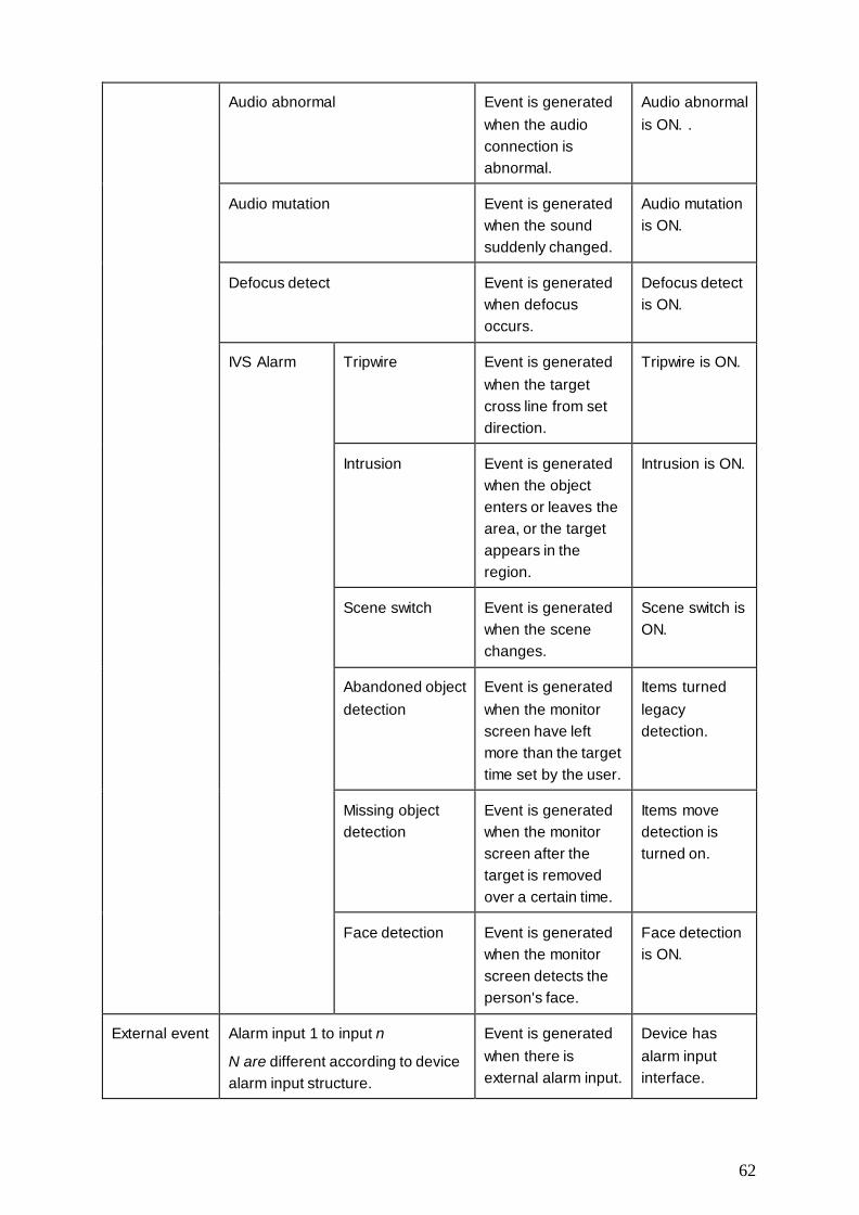
The event type Event Note Condition
Channel event Video loss Network abnormality
causing video loss
Video loss
detection is ON.
Video tampering Event is generated
when video is
tampered.
Video
tampering is
ON.
Motion detect Event is generated
when it is detected
moving object in
video.
Motion detect is
ON.
62
Audio abnormal Event is generated
when the audio
connection is
abnormal.
Audio abnormal
is ON. .
Audio mutation Event is generated
when the sound
suddenly changed.
Audio mutation
is ON.
Defocus detect Event is generated
when defocus
occurs.
Defocus detect
is ON.
IVS Alarm Tripwire Event is generated
when the target
cross line from set
direction.
Tripwire is ON.
Intrusion Event is generated
when the object
enters or leaves the
area, or the target
appears in the
region.
Intrusion is ON.
Scene switch Event is generated
when the scene
changes.
Scene switch is
ON.
Abandoned object
detection
Event is generated
when the monitor
screen have left
more than the target
time set by the user.
Items turned
legacy
detection.
Missing object
detection
Event is generated
when the monitor
screen after the
target is removed
over a certain time.
Items move
detection is
turned on.
Face detection Event is generated
when the monitor
screen detects the
person's face.
Face detection
is ON.
External event Alarm input 1 to input n
N are different according to device
alarm input structure.
Event is generated
when there is
external alarm input.
Device has
alarm input
interface.

63
Device Event No disks Event is generated
when the device
does not have
storage devices.
No disks is ON
(SD card or
hard disk).
Disk fault Event is generated
when the device has
hard disk failures.
Disk fault is
ON.
Disk full Event is generated
when the device
disk is full.
Disk full is ON.
Illegal access When the login
password you enter
are consecutively
incorrect, and reach
the limit, event is
triggered.
Illegal access is
ON.
11.2 Event Alarm Link Config
11.2.1 Link Notice
After set link notice, when event occurs, it will alarm or alarm flash on map.
Step 1. In New tab, click Event CFG.
Step 2. Click device and select event type.
Step 3. Slide to turn on event, click Notify tab. See Figure 11-2.

64
Figure 11-2
Step 4. According to need, slide to enable alarm sound or map flash.
Step 5. Click Save.
Click Copy to, you can link config of this camera to other device.
11.2.2 Link Video
After you link video, when corresponding event occurs, it will link corresponding camera preview
or record.
Step 1. In New tab, click Event CFG.
Step 2. Click device and select event type.
Step 3. Slide , to enable event, and click Video tab. See Figure 11-3.

65
Figure 11-3
Step 4. Select video window, and double click camera you want to link, directly drag it into
window.
Note:
On , you can set display mode.
Step 5. In camera list to be linked, set camera preset, link record or preview stream type,
whether auto open video and enable record when event occurs, linked record or preview
duration.
Note:
Click , you can delete camera.
Step 6. Click Save.

66
Click Copy to, you can copy camera link config to other devices.
11.2.3 Link Alarm Output
After you config link alarm output, when alarm occurs, it will link corresponding
camera alarm output.
Step 1. In New tab, click Event CFG.
Step 2. Click device and select event type.
Step 3. Slide to enable event, and click Alarm Out tab. See Figure 11-4.
Figure 11-4
Step 4. Select alarm output of link camera and set whether to auto enable and duration.
Step 5. Click Save.
Click Copy to, you can copy camera link config to other devices.

67
11.2.4 Arm Time
Event is armed all-day by default. You can set arm time as needed.
Step 1. In New tab, click Event CFG.
Step 2. Click device and select event type.
Step 3. Slide to enable event and click Arm Time tab. See Figure 11-5.,
Figure 11-5
Step 4. In corresponding day of week drag mouse to delete to add arm time. You also can click
of each day of week to set arm time in pop-up box.
Step 5. Click Save.
Click Copy to, you can copy camera arm time config to other devices.

68
11.3 Event View
You can view the alarm event information, disable event sounds or disable alarm linkage pop
video, pause refresh of event information.
In homepage, click or in New tab, select the Event, see Figure 11-6.
In the Event interface you can view real-time alarm information, view up to 1000 latest
messages, please search historical alarm message in log, see Ch 7.
Select event, you can check Disable sound to disable the alarm sound for event; check Stop
link video popup to prohibit pop-up video; check Stop refresh to pause refresh of event.
Select event, click the Confirm, you can add a description to the event.
After you handle event or confirm event, you cannot change the status of the event.
Figure 11-6

69
12. Video Wall
12.1 Video Wall
You can set video wall layout, live preview on wall, scheme and tour plus playback on wall.
In New tab, click Video Wall, see Figure 12-1.
Figure 12-1
Serial number Task Note
1 Device list When set Default Device Tree to Device Tree (by device),
the device tree displays device group and channels for the device.
When set Default Device Tree to Area Tree (by channel), the device tree displays device channels.
See Ch 8.
Preview Right click device channel and select Preview, display
corresponding device channel in the Preview area. Select video wall with bound device channel, in Window
Details area>Operation column, click , corresponding video will be displayed in the video preview area.
Switch
stream
You can switch stream through the following two ways.
Right click device channel and select stream type, and set the desired stream.
70
Select video wall with bound device channel, right click to select stream type, and set the desired stream.
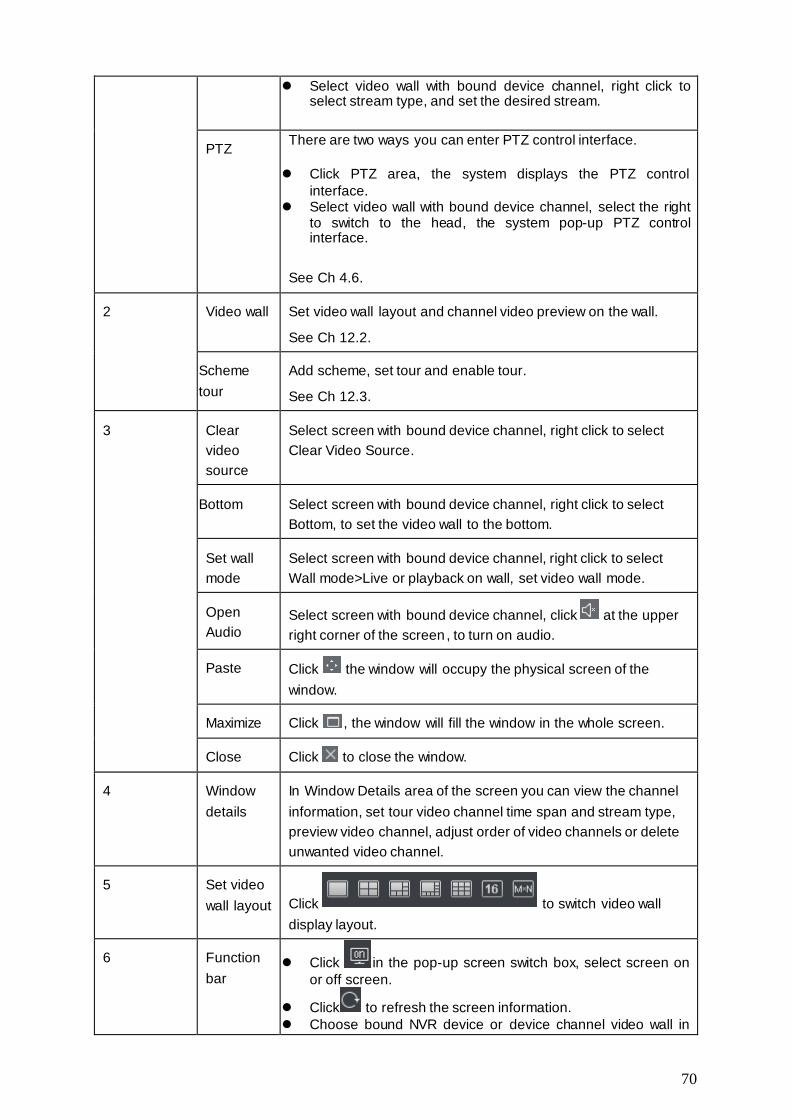
PTZ There are two ways you can enter PTZ control interface.
Click PTZ area, the system displays the PTZ control
interface. Select video wall with bound device channel, select the right
to switch to the head, the system pop-up PTZ control interface.
See Ch 4.6.
2 Video wall Set video wall layout and channel video preview on the wall.
See Ch 12.2.
Scheme
tour
Add scheme, set tour and enable tour.
See Ch 12.3.
3 Clear
video
source
Select screen with bound device channel, right click to select
Clear Video Source.
Bottom Select screen with bound device channel, right click to select
Bottom, to set the video wall to the bottom.
Set wall
mode
Select screen with bound device channel, right click to select
Wall mode>Live or playback on wall, set video wall mode.
Open
Audio
Select screen with bound device channel, click at the upper
right corner of the screen , to turn on audio.
Paste Click the window will occupy the physical screen of the
window.
Maximize Click , the window will fill the window in the whole screen.
Close Click to close the window.
4 Window
details
In Window Details area of the screen you can view the channel
information, set tour video channel time span and stream type,
preview video channel, adjust order of video channels or delete
unwanted video channel.
5 Set video
wall layout Click to switch video wall
display layout.
6 Function
bar Click in the pop-up screen switch box, select screen on
or off screen.
Click to refresh the screen information.
Choose bound NVR device or device channel video wall in

71
group, click to open tour; click to close tout.
Click to delete the selected window.
Click to clear the screen.
Click , you can select multiple windows, then the icon
changes to ; click a window.
Click to display window number and video wall number.
12.2 Set Video Wall and Output
Condition
Decoder and video wall are connected successfully.
Steps
Step 1. Add decoder, see Ch 3.
Step 2. Set video wall layout.
a) In video wall interface, click in pop-up box. See Figure 12-2.
Note:
Select multiple screens, click to add splicing screen; select splicing screens, click to
cancel splicing screen; click to clear screen config.

72
Figure 12-2
b) In basic config interface, set video wall name, select
Layout, and click in video wall, to add video wall layout.
c) Click Next. See Figure 12-3.
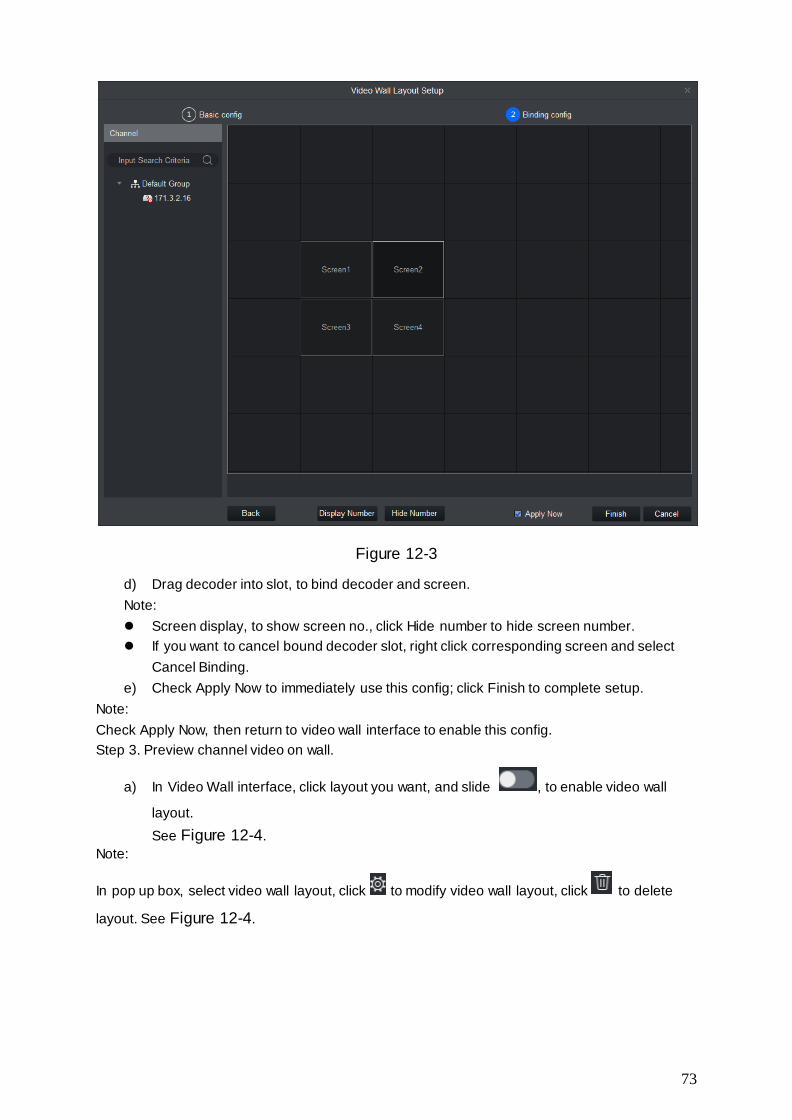
73
Figure 12-3
d) Drag decoder into slot, to bind decoder and screen.
Note:
Screen display, to show screen no., click Hide number to hide screen number.
If you want to cancel bound decoder slot, right click corresponding screen and select
Cancel Binding.
e) Check Apply Now to immediately use this config; click Finish to complete setup.
Note:
Check Apply Now, then return to video wall interface to enable this config.
Step 3. Preview channel video on wall.
a) In Video Wall interface, click layout you want, and slide , to enable video wall
layout.
See Figure 12-4.
Note:
In pop up box, select video wall layout, click to modify video wall layout, click to delete
layout. See Figure 12-4.
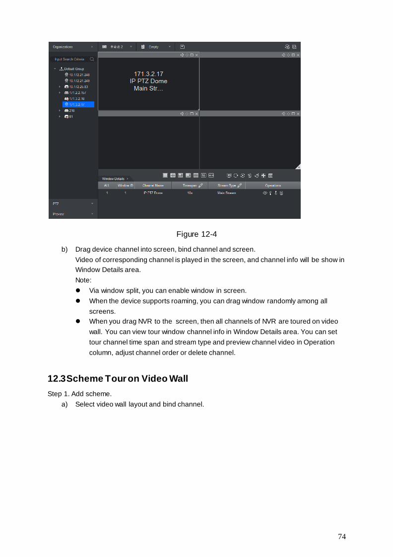
74
Figure 12-4
b) Drag device channel into screen, bind channel and screen.
Video of corresponding channel is played in the screen, and channel info will be show in
Window Details area.
Note:
Via window split, you can enable window in screen.
When the device supports roaming, you can drag window randomly among all
screens.
When you drag NVR to the screen, then all channels of NVR are toured on video
wall. You can view tour window channel info in Window Details area. You can set
tour channel time span and stream type and preview channel video in Operation
column, adjust channel order or delete channel.
12.3 Scheme Tour on Video Wall
Step 1. Add scheme.
a) Select video wall layout and bind channel.

75
b) Click .See Figure 12-5.
Figure 12-5
c) Set scheme name, click Save.
Repeat step a to c to add more schemes.
Step 2. Set scheme tour.
a) Click . See Figure 12-6.
Figure 12-6
b) Set time span and select scheme, click Add Scheme. Repeat this step to add more
schemes.
Note:
You can adjust scheme order and delete scheme in Operation column.
c) Click Save.
Step 3. Click to enable scheme tour.

76
Click , to disable scheme tour.
12.4 Playback on Video Wall
Playback device channel record on video wall.
Condition
Complete video wall config.
Record exists in device channel.
Steps
Step 1. Select screen with bound device channel, right click Video Wall>Playback on Video Wall.
See Figure 12-7.
Figure 12-7
Step 2. Select record type and stream type, and set time.
Step 3. Click Search.
Step 4. Select record file, click to playback record.

77
13. People Count
You can search and export people count result, contrast by time and channel and export people
count data.
Condition
Enabled entrance/exit statistics function.
Entrance/exit statistical data exists in device.
Steps
Step 1. In New tab, click People Count. See Figure 13-1.
Figure 13-1
Step 2. Select channel with people count data, and set time and period for search.
Note:
You can search people count data by date, time, year or month.
If you select multiple channel, then it will search data of these channels in search period
Step 3. Click Search.
The system shows people count result in this period, see Figure 13-2.
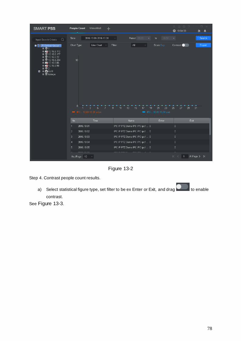
78
Figure 13-2
Step 4. Contrast people count results.
a) Select statistical figure type, set filter to be ex Enter or Exit, and drag to enable
contrast.
See Figure 13-3.

79
Figure 13-3
b) Set contrast type to Channel and select channel for contrast. This contrasts people
count results of different channels within the same period. Set contrast type to Time and
select time for contrast. This contrasts people count results of different periods for the
same channel. System shows result.
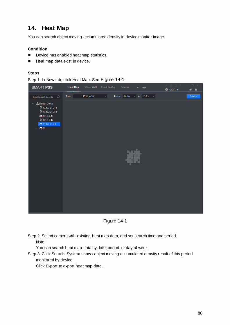
80
14. Heat Map
You can search object moving accumulated density in device monitor image.
Condition
Device has enabled heat map statistics.
Heal map data exist in device.
Steps
Step 1. In New tab, click Heat Map. See Figure 14-1.
Figure 14-1
Step 2. Select camera with existing heat map data, and set search time and period.
Note:
You can search heat map data by date, period, or day of week.
Step 3. Click Search. System shows object moving accumulated density result of this period
monitored by device.
Click Export to export heat map date.
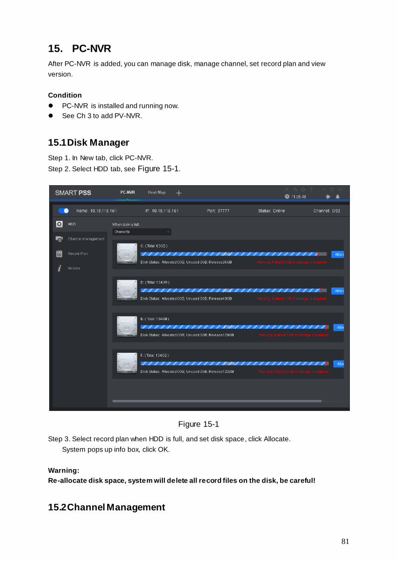
81
15. PC-NVR
After PC-NVR is added, you can manage disk, manage channel, set record plan and view
version.
Condition
PC-NVR is installed and running now.
See Ch 3 to add PV-NVR.
15.1 Disk Manager
Step 1. In New tab, click PC-NVR.
Step 2. Select HDD tab, see Figure 15-1.
Figure 15-1
Step 3. Select record plan when HDD is full, and set disk space, click Allocate.
System pops up info box, click OK.
Warning:
Re-allocate disk space, system will delete all record files on the disk, be careful!
15.2 Channel Management

82
Set channel info to pass PC-NVR record plan.
Step 1. In New tab, click PC-NVR.
Step 2. Select Channel Management tab, see Figure 15-2.
Figure 15-2
Step 3. In device list select device channel, click . System will add the selected
device channel to list on the right.
Note:
Click to add device channel and shown in thumbnail, click to add device channel
and shown in list.
If you delete unwanted device channel, check box in front of one device channel or
check Selected channel to select all channels, click to delete.
Step 4. Click Save.
15.3 Set Record Plan
For the selected channel, set record schedule, motion detect, alarm, MD& alarm, or smart record
plan.
Step 1. In New tab, click PC-NVR.
Step 2. Select Record Plan tab. See Figure 15-3.

83
Figure 15-3
Step 3. Select channel to set record plan, select stream type, set pre-record time and delay
record time.
Step 4. Check record type, and select record time in corresponding day of week bar.
Note:
You can click next to each day of week bar, and in pop-up box set record type and
period.
Step 5. Click Save.
Note:
Click Copy to, and check device channel, you can copy the record plan in this channel
to other device channel.
Click Default to restore default status of device channel record plan.
15.4 Version Info
You can view PC-NVR name, storage path and version.
Step 1. In New tab, click PC-NVR.
Step 2. Select Version tab, see Figure 15-4.
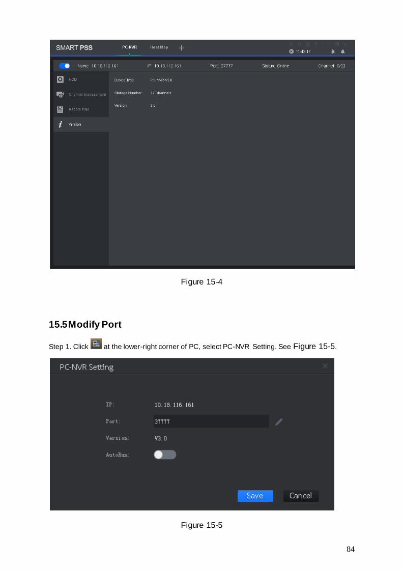
84
Figure 15-4
15.5 Modify Port
Step 1. Click at the lower-right corner of PC, select PC-NVR Setting. See Figure 15-5.
Figure 15-5

85
Step 2. Click and enter port no. you want.
If you slide to enable auto ON, after PC boots up, PC-NVR will be ON automatically.
Step 3. Click Save.
15.6 Modify Password
Step 1. Click at the lower-right corner of PC, select Password Setting. See Figure 15-6.
Figure 15-6
Step 2. Enter original password, and enter new password, confirm new password.
Step 3. Click Save.
Note:
This manual is for reference only. Slight difference may be found in the user
interface.
All the designs and software here are subject to change without prior written
notice.
All trademarks and registered trademarks are the properties of their respective
owners.
If there is any uncertainty or controversy, please refer to the final explanation of us.
Please visit our website or contact your local service engineer for more
information.