Smart positioner YT-3300 / 3301 / 3302 / 3303 / 3350 ... Product... · 1 Smart positioner YT-3300 /...
14
1 Smart positioner YT-3300 / 3301 / 3302 / 3303 / 3350 / 3400 / 3410 / 3450 Series SIL Safety Instruction. Supplement to product manual July. 2015 YTC Ver 1.06
Transcript of Smart positioner YT-3300 / 3301 / 3302 / 3303 / 3350 ... Product... · 1 Smart positioner YT-3300 /...
1
Smart positioner
YT-3300 / 3301 / 3302 / 3303 / 3350 / 3400 /
3410 / 3450 Series
SIL Safety Instruction.
Supplement to product manual
July. 2015
YTC Ver 1.06
2
Table of contents
1 Introduction ............................................................................................................................................................................. 3
1.1 Purpose of this document ....................................................................................................................................... 3
1.2 Field of Application ..................................................................................................................................................... 3
1.3 Required documentation .......................................................................................................................................... 3
1.4 Further information ..................................................................................................................................................... 3
2 Acronyms and abbreviations ........................................................................................................................................... 4
3 Relevant standards ............................................................................................................................................................... 5
4 Terms and definitions .......................................................................................................................................................... 5
5 Determining the Safety Integrity Level (SIL) ............................................................................................................ 5
6 Safety-related system .......................................................................................................................................................... 7
7 Information for the safety function .............................................................................................................................. 8
8 Periodic checks ....................................................................................................................................................................... 9
9 Safety engineering parameters ................................................................................................................................... 10
9.1 Prerequisites ................................................................................................................................................................. 10
9.2 Specific safety-related parameters .................................................................................................................... 10
10 Glossary ............................................................................................................................................................................... 11
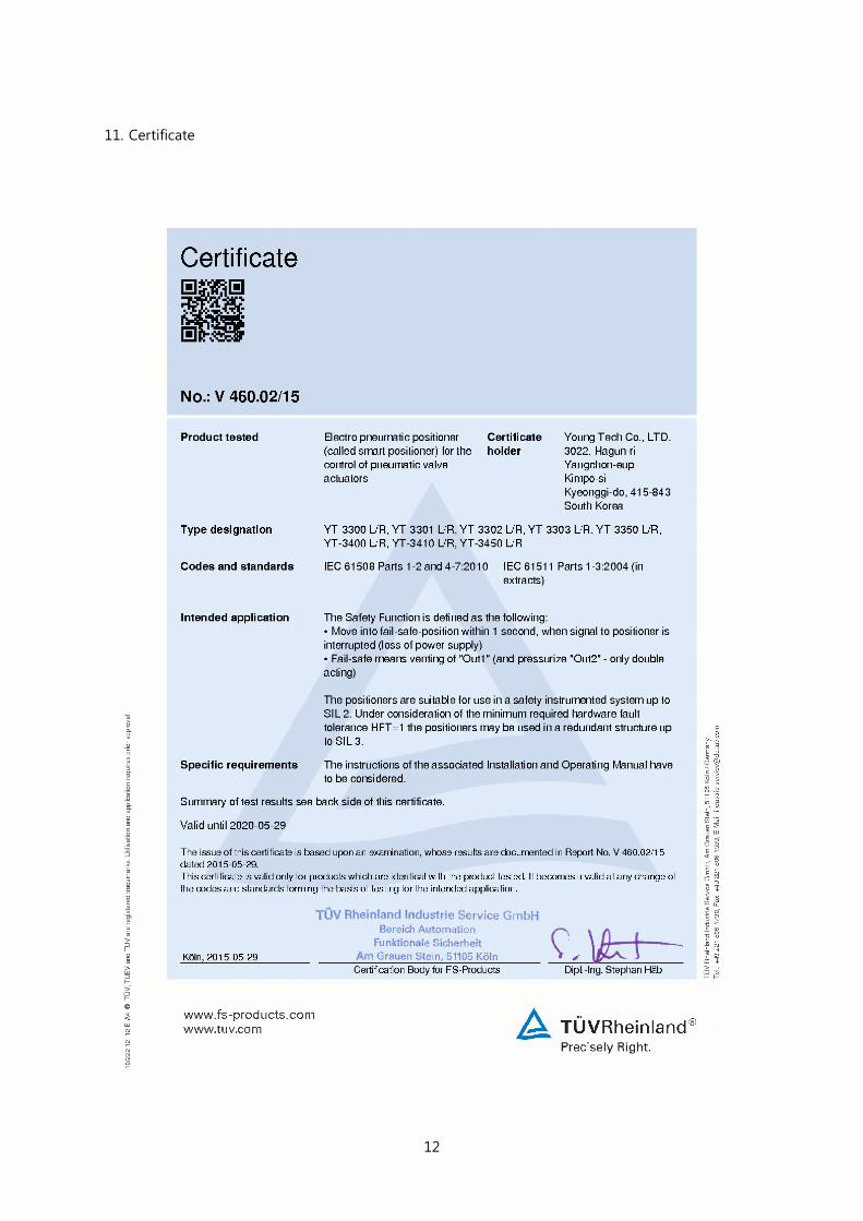
11 Certificate ............................................................................................................................................................................ 12
3
1 Introduction
1.1 Purpose of this document
This document contains information and safety instructions that the user will require when using
the electro pneumatic positioner in safety-related systems.
This document is for system planners, constructors, service & maintenance engineers and
personnel who will perform commissioning the device.
1.2 Field of Application
The application includes control valve with pneumatic positioners with positioning control up
to SIL2 level in accordance with the safety engineering requirements of IEC61508.
positioners are suitable for SIL2 at HFT=0 and for SIL3 at HFT=1
In the event of an electrical power failure, the single-acting positioner depressurizes the actuator
chamber, and the movement of actuator’s return spring, as a result, moves the valve to the
predefined, safe end position (either OPEN or CLOSED). For double-acting positioner, it
depressurizes the actuator through Out1 port and pressurizes the actuator through Out2 port
in order to moves the valve to the predefined, safe end position (either OPEN or CLOSED)
1.3 Required documentation
This document only defines YT-3300/3301/3302/3303/3350/3400/3410/3450 positioner’s
safety functions.
This document only applies in conjunction withYT-3300/3301/3302/3303/3350/3400/3410/
3450 Product Manual.
1.4 Further information
The contents of these instructions shall not become part of or modify any prior existing
agreement, commitment or legal matter.
Any statements contained herein do not create new warranties or modify the existing warranty.
The content reflects the technical status at the time of printing.
YTC reserves the right to make technical changes in the course of further development.
4
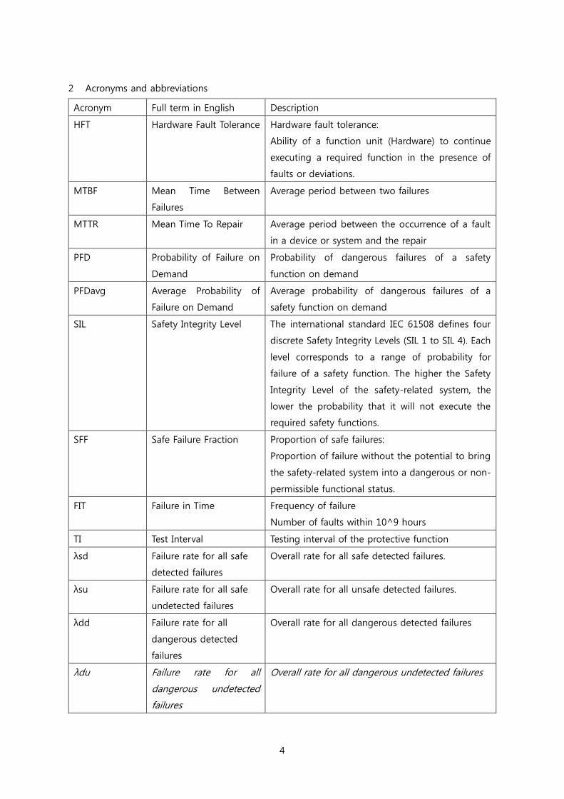
2 Acronyms and abbreviations
Acronym Full term in English Description
HFT Hardware Fault Tolerance Hardware fault tolerance:
Ability of a function unit (Hardware) to continue
executing a required function in the presence of
faults or deviations.
MTBF Mean Time Between
Failures
Average period between two failures
MTTR Mean Time To Repair Average period between the occurrence of a fault
in a device or system and the repair
PFD Probability of Failure on
Demand
Probability of dangerous failures of a safety
function on demand
PFDavg Average Probability of
Failure on Demand
Average probability of dangerous failures of a
safety function on demand
SIL Safety Integrity Level The international standard IEC 61508 defines four
discrete Safety Integrity Levels (SIL 1 to SIL 4). Each
level corresponds to a range of probability for
failure of a safety function. The higher the Safety
Integrity Level of the safety-related system, the
lower the probability that it will not execute the
required safety functions.
SFF Safe Failure Fraction Proportion of safe failures:
Proportion of failure without the potential to bring
the safety-related system into a dangerous or non-
permissible functional status.
FIT Failure in Time Frequency of failure
Number of faults within 10^9 hours
TI Test Interval Testing interval of the protective function
λsd Failure rate for all safe
detected failures
Overall rate for all safe detected failures.
λsu Failure rate for all safe
undetected failures
Overall rate for all unsafe detected failures.
λdd Failure rate for all
dangerous detected
failures
Overall rate for all dangerous detected failures
λdu Failure rate for all
dangerous undetected
failures
Overall rate for all dangerous undetected failures
5
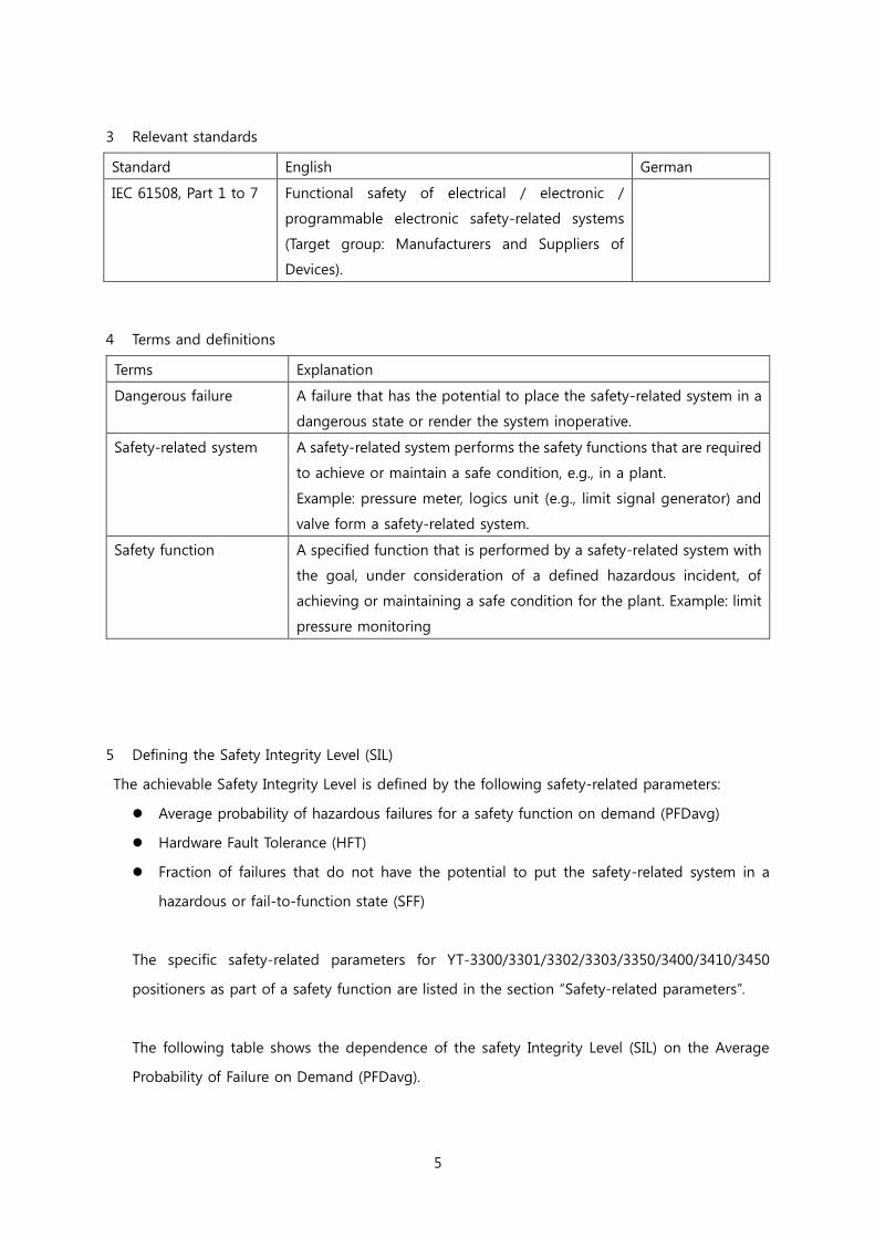
3 Relevant standards
Standard English German
IEC 61508, Part 1 to 7 Functional safety of electrical / electronic /
programmable electronic safety-related systems
(Target group: Manufacturers and Suppliers of
Devices).
4 Terms and definitions
Terms Explanation
Dangerous failure A failure that has the potential to place the safety-related system in a
dangerous state or render the system inoperative.
Safety-related system A safety-related system performs the safety functions that are required
to achieve or maintain a safe condition, e.g., in a plant.
Example: pressure meter, logics unit (e.g., limit signal generator) and
valve form a safety-related system.
Safety function A specified function that is performed by a safety-related system with
the goal, under consideration of a defined hazardous incident, of
achieving or maintaining a safe condition for the plant. Example: limit
pressure monitoring
5 Defining the Safety Integrity Level (SIL)
The achievable Safety Integrity Level is defined by the following safety-related parameters:
Average probability of hazardous failures for a safety function on demand (PFDavg)
Hardware Fault Tolerance (HFT)
Fraction of failures that do not have the potential to put the safety-related system in a
hazardous or fail-to-function state (SFF)
The specific safety-related parameters for YT-3300/3301/3302/3303/3350/3400/3410/3450
positioners as part of a safety function are listed in the section “Safety-related parameters”.
The following table shows the dependence of the safety Integrity Level (SIL) on the Average
Probability of Failure on Demand (PFDavg).
6
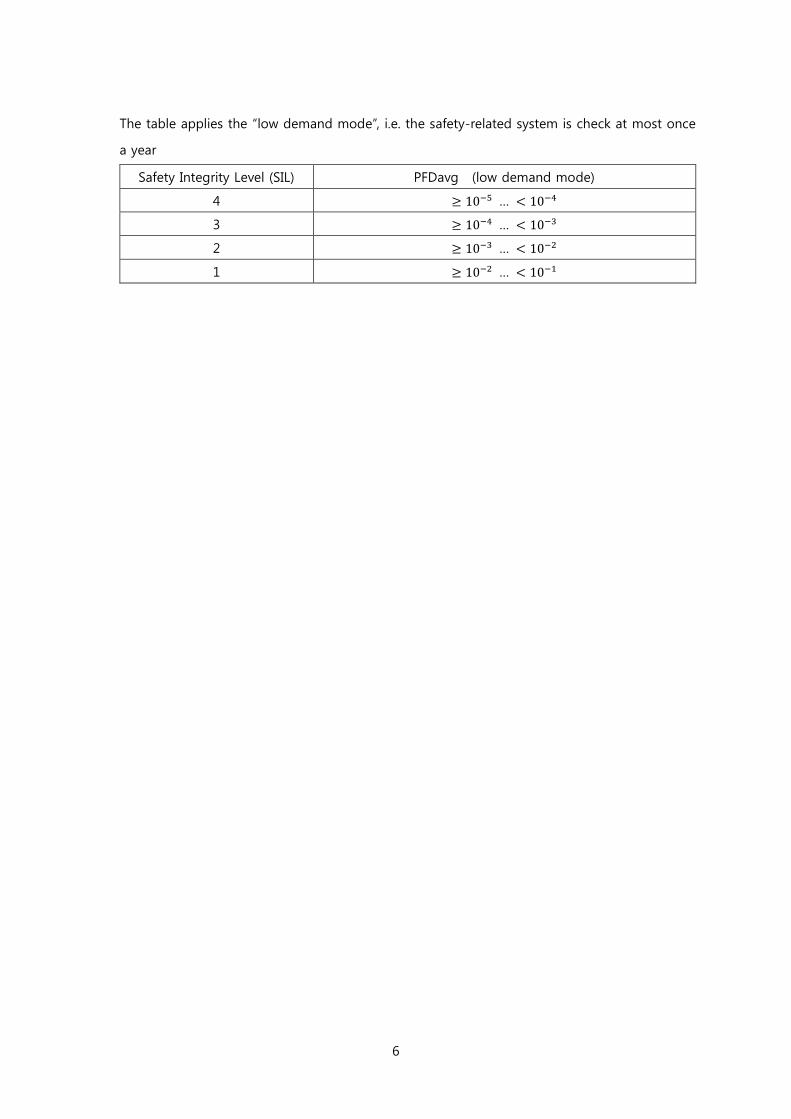
The table applies the “low demand mode”, i.e. the safety-related system is check at most once
a year
Safety Integrity Level (SIL) PFDavg (low demand mode)
4 ≥ 10−5 … < 10−4
3 ≥ 10−4 … < 10−3
2 ≥ 10−3 … < 10−2
1 ≥ 10−2 … < 10−1
7
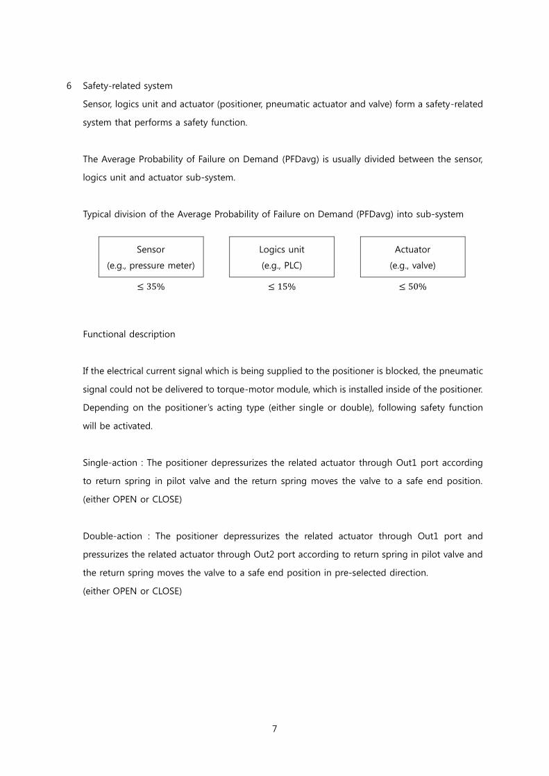
6 Safety-related system
Sensor, logics unit and actuator (positioner, pneumatic actuator and valve) form a safety-related
system that performs a safety function.
The Average Probability of Failure on Demand (PFDavg) is usually divided between the sensor,
logics unit and actuator sub-system.
Typical division of the Average Probability of Failure on Demand (PFDavg) into sub-system
Sensor
(e.g., pressure meter)
Logics unit
(e.g., PLC)
Actuator
(e.g., valve)
≤ 35% ≤ 15% ≤ 50%
Functional description
If the electrical current signal which is being supplied to the positioner is blocked, the pneumatic
signal could not be delivered to torque-motor module, which is installed inside of the positioner.
Depending on the positioner ’s acting type (either single or double), following safety function
will be activated.
Single-action : The positioner depressurizes the related actuator through Out1 port according
to return spring in pilot valve and the return spring moves the valve to a safe end position.
(either OPEN or CLOSE)
Double-action : The positioner depressurizes the related actuator through Out1 port and
pressurizes the related actuator through Out2 port according to return spring in pilot valve and
the return spring moves the valve to a safe end position in pre-selected direction.
(either OPEN or CLOSE)
8
7 Information for the safety function
Important
Safety-related systems without a self-locking function must be monitored or set to an otherwise
safe condition after performing the safety function within MTTR (8 hours).
The device lifecycle must be evaluated according to the specified MTBF.
9
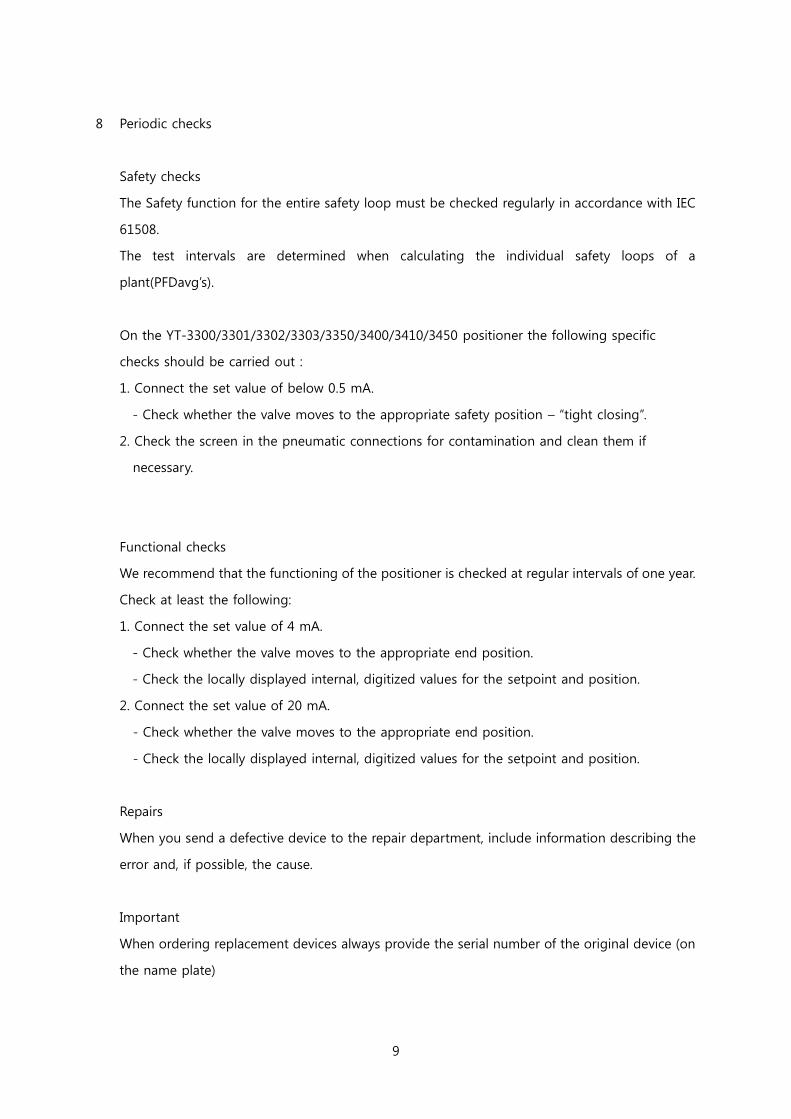
8 Periodic checks
Safety checks
The Safety function for the entire safety loop must be checked regularly in accordance with IEC
61508.
The test intervals are determined when calculating the individual safety loops of a
plant(PFDavg’s).
On the YT-3300/3301/3302/3303/3350/3400/3410/3450 positioner the following specific
checks should be carried out :
1. Connect the set value of below 0.5 mA.
- Check whether the valve moves to the appropriate safety position – “tight closing”.
2. Check the screen in the pneumatic connections for contamination and clean them if
necessary.
Functional checks
We recommend that the functioning of the positioner is checked at regular intervals of one year.
Check at least the following:
1. Connect the set value of 4 mA.
- Check whether the valve moves to the appropriate end position.
- Check the locally displayed internal, digitized values for the setpoint and position.
2. Connect the set value of 20 mA.
- Check whether the valve moves to the appropriate end position.
- Check the locally displayed internal, digitized values for the setpoint and position.
Repairs
When you send a defective device to the repair department, include information describing the
error and, if possible, the cause.
Important
When ordering replacement devices always provide the serial number of the original device (on
the name plate)
10
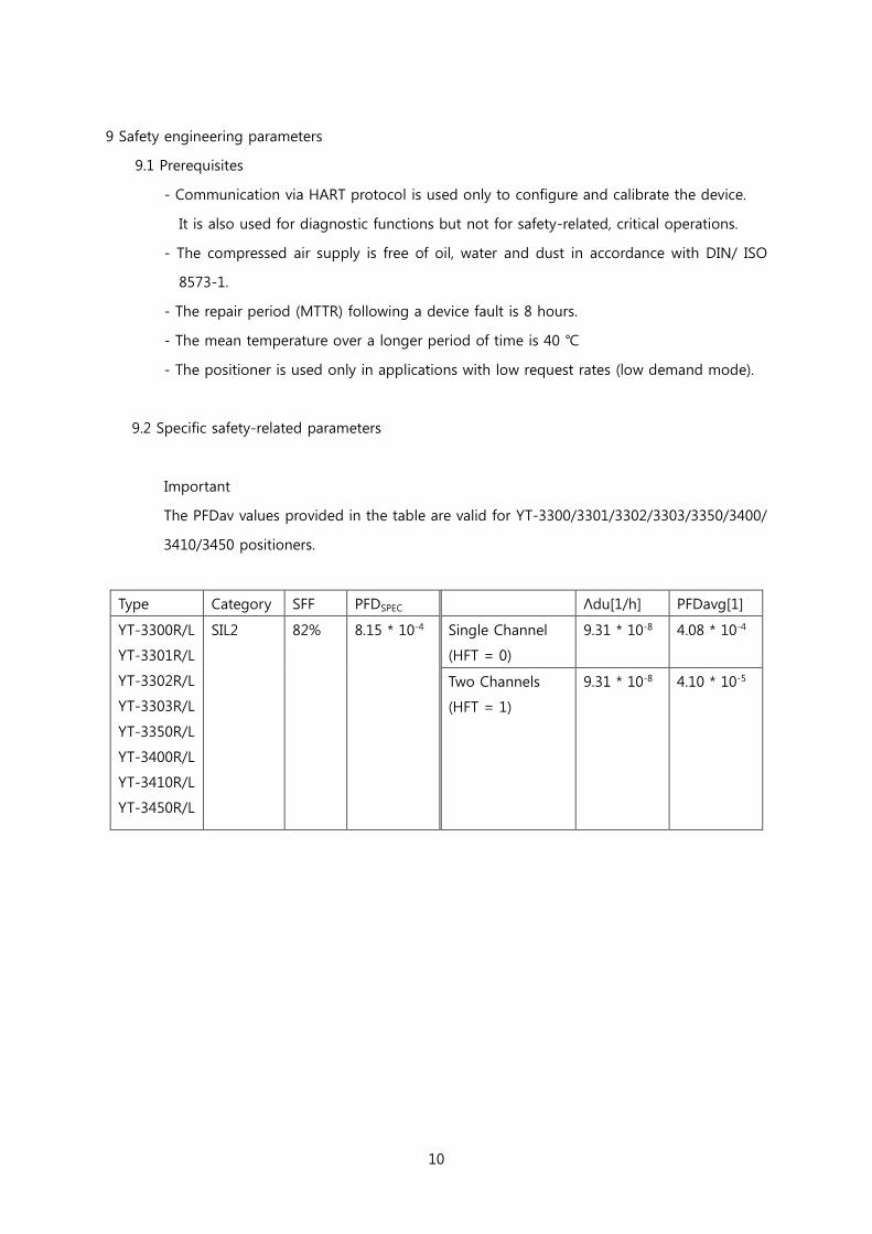
9 Safety engineering parameters
9.1 Prerequisites
- Communication via HART protocol is used only to configure and calibrate the device.
It is also used for diagnostic functions but not for safety-related, critical operations.
- The compressed air supply is free of oil, water and dust in accordance with DIN/ ISO
8573-1.
- The repair period (MTTR) following a device fault is 8 hours.
- The mean temperature over a longer period of time is 40 ℃
- The positioner is used only in applications with low request rates (low demand mode).
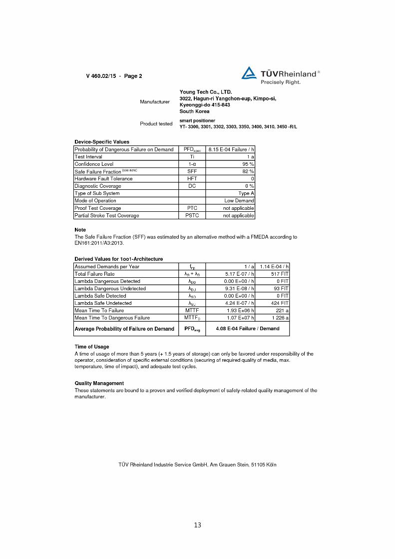
9.2 Specific safety-related parameters
Important
The PFDav values provided in the table are valid for YT-3300/3301/3302/3303/3350/3400/
3410/3450 positioners.
Type Category SFF PFDSPEC Λdu[1/h] PFDavg[1]
YT-3300R/L
YT-3301R/L
YT-3302R/L
YT-3303R/L
YT-3350R/L
YT-3400R/L
YT-3410R/L
YT-3450R/L
SIL2 82% 8.15 * 10-4 Single Channel
(HFT = 0)
9.31 * 10-8 4.08 * 10-4
Two Channels
(HFT = 1)
9.31 * 10-8 4.10 * 10-5
11
10 Glossary
Dangerous failure
Failure with the potential to bring the safety-related system into a dangerous or non-
functional status.
Safety function
Defined function executed by a safety-related system with the objective of achieving or
maintaining a safe system status taking into account a defined dangerous occurrence.
Example:
Limit pressure monitoring
Safety Integrity Level
Safety-related system
A safety-related system executes the safety functions that are required to achieve or
maintain a safe status in a system.
It consists of a sensor, logic unit/control system and final controlling element.
Example:
A safety-related system is made up of a pressure transmitter, a limit signal sensor and a
control valve.
SIL
The international standard IEC 61508 defines four discrete Safety Integrity Level (SIL) from
SIL 1 to SIL 4. Each level corresponds to the probability range for the failure of a safety
function. The higher the SIL of the safety-related system, the higher probability that the
required safety function will work.
12
11. Certificate
13
14
Manufacturer:
Young Tech Co., Ltd
81, Hwanggeum-ro, 89 beon-gil, Yangchon-eup
Kimpo-si, Kyeonggi-do, 415-843
South Korea
Tel:
Fax:
Email:
+82-31-986-8545
+82-31-986-2683
Copyright ⓒ Young Tech Co., Ltd. All Rights Reserved.