
Smart Laser Sensors E3NC - Omron · 2018-05-21 · Smart Laser Sensors E3NC Ideal for Applications...
28
CSM_E3NC_DS_E_3_1 1 Smart Laser Sensors E3NC Ideal for Applications That Cannot Be Handled with Fiber Sensors or Photoelectric Sensors • A wide variety of easy-to-use Laser Photoelectric Sensor Heads. • Coaxial Retro-reflective Models (E3NC-LH03). • Long-distance, variable spot, Diffuse-reflective Models (E3NC-LH02) • Small-spot (0.1 mm dia.), Limited-reflective Models (E3NC-LH01). • CMOS Reflective Models (E3NC-SH series). • Smart Tuning to achieve stable detection with easy setup. • White on black display characters for high visibility. • Robot cables for reliable operation in harsh environments. Features Retro-reflective Models: E3NC-LH03 • Maximum sensing distance of 8 m. • Stable detection of many types of workpieces. • Stable detection of highly transparent films. CMOS Laser, Reflective Models: E3NC-SH250H/SH250/SH100 • Stable detection even for different workpiece colors and materials. • Stable detection for inclined Head installation and different workpiece shapes. Diffuse-reflective Models: E3NC-LH02 • Long-distance detection at up to 1.2 m. • Spot can be adjusted to the workpiece or application. Amplifier Units • Same shape as Fiber Amplifier Units plus easy operation. • Smart Tuning with one button. For the most recent information on models that have been certified for safety standards, refer to your OMRON website. Refer to the Safety Precautions on page 14. 8 m Glossy metal White ceramic Black rubber Cast metal Glossy tl White i Black bb Cast tl PAT.P 0.8 mm dia. or larger ger g 0.8 mm di a. or l arg
Transcript of Smart Laser Sensors E3NC - Omron · 2018-05-21 · Smart Laser Sensors E3NC Ideal for Applications...

CSM_E3NC_DS_E_3_1
1
Smart Laser Sensors
E3NCIdeal for Applications That Cannot Be Handled with Fiber Sensors or Photoelectric Sensors
• A wide variety of easy-to-use Laser Photoelectric Sensor Heads.
• Coaxial Retro-reflective Models (E3NC-LH03).• Long-distance, variable spot, Diffuse-reflective Models
(E3NC-LH02)• Small-spot (0.1 mm dia.), Limited-reflective Models
(E3NC-LH01).• CMOS Reflective Models (E3NC-SH series).
• Smart Tuning to achieve stable detection with easy setup.• White on black display characters for high visibility.• Robot cables for reliable operation in harsh environments.
FeaturesRetro-reflective Models: E3NC-LH03• Maximum sensing distance of 8 m.• Stable detection of many types of workpieces.• Stable detection of highly transparent films.
CMOS Laser, Reflective Models: E3NC-SH250H/SH250/SH100• Stable detection even for different workpiece colors and materials.• Stable detection for inclined Head installation and different
workpiece shapes.
Diffuse-reflective Models: E3NC-LH02 • Long-distance detection at up to 1.2 m.• Spot can be adjusted to the workpiece or application.
Amplifier Units• Same shape as Fiber Amplifier Units plus easy operation.• Smart Tuning with one button.
For the most recent information on models that have been certified for safety standards, refer to your OMRON website.
Refer to the Safety Precautions on page 14.
8 m
Glossy metal
White ceramic
Black rubber
Cast metal
Glossyt l
Whitei
Black bb
Cast t l
PAT.P
0.8 mm dia. or largergerg0.8 mm dia. or larg

E3NC
2
Ordering InformationSensor Heads: E3NC-L Compact Laser Sensor Series (Dimensions ➜ page 17)
* These values apply when an E39-R21, E39-R22, E39-RS10, or E39-RS11 Reflector is used. A Reflector is not included. Purchase a Reflector separately to matchthe intended use of the Sensor.
Note: Only an E3NC-LA@@ Amplifier Unit can be connected.
Amplifier Units: E3NC-L Compact Laser Sensor Series (Dimensions ➜ page 19)
* A Sensor Communications Unit is required if you want to use the Amplifier Unit on a network.Note: Only an E3NC-LH@@ Sensor Head can be connected.
Sensor Heads: E3NC-S Ultra-compact CMOS Laser Sensor Series (Dimensions ➜ page 18)
Note: Only an E3NC-SA@@ Amplifier Unit can be connected.
Sensing method Appearance Beam shape Sensing distance Laser
class Cable length Model
Coaxial Retro-reflective with MSR function
Spot
Class 1
2 m E3NC-LH03 2M
5 m E3NC-LH03 5M
Diffuse-reflective Variable spot
2 m E3NC-LH02 2M
5 m E3NC-LH02 5M
Limited-reflective Spot
2 m E3NC-LH01 2M
5 m E3NC-LH01 5M
Connecting method Appearance Inputs/outputsModel
NPN output PNP output
Pre-wired (2 m) 2 outputs + 1 input E3NC-LA21 2M E3NC-LA51 2M
Wire-saving Connector 1 output + 1 input E3NC-LA7 E3NC-LA9
M8 Connector 1 output + 1 input E3NC-LA24 E3NC-LA54
Connector for Sensor Communications Unit * --- E3NC-LA0
Sensing method Appearance Beam shape Measurement range Laser
class Cable length Model
Distance-settable Spot
Class 2 2 m E3NC-SH250H 2M
Class 1
2 m E3NC-SH250 2M
2 m E3NC-SH100 2M
8 m *
1.2 m
70±15 mm
35 to 250 mm
35 to 100 mm

E3NC
3
Amplifier Units: E3NC-S Ultra-compact CMOS Laser Sensor Series (Dimensions ➜ page 19)
* A Sensor Communications Unit is required if you want to use the Amplifier Unit on a network.Note: Only an E3NC-SH@@ or E3NC-SH@@H Sensor Head can be connected.
Accessories (Sold Separately)Sensor Head AccessoriesReflectors for Retro-reflective Sensors (Dimensions ➜ page 21)A Reflector is not provided with the Sensor Head. It must be ordered separately as required.
Lens Attachments for Sensor Heads (Dimensions ➜ page 21)A Lens Attachment is not provided with the Sensor Head. It must be ordered separately as required.
Note: You can combine the Lens Attachment with an applicable Sensor Head to create a line beam.
Sensor Head Mounting Brackets (Dimensions ➜ page 22)A Mounting Bracket is not provided with the Sensor Head. It must be ordered separately as required.
Connecting method Appearance Inputs/outputsModel
NPN output PNP output
Pre-wired (2 m) 2 outputs + 1 input E3NC-SA21 2M E3NC-SA51 2M
Wire-saving Connector 1 output + 1 input E3NC-SA7 E3NC-SA9
M8 Connector 1 output + 1 input E3NC-SA24 E3NC-SA54
Connector for Sensor Communications Unit * --- E3NC-SA0
Applicable Sensor Head Appearance Model Quantity
E3NC-LH03
E39-R21
1
E39-R22
E39-RS10
E39-RS11
Applicable Sensor Head Appearance Model Quantity
E3NC-LH03 E39-P51
1
E3NC-LH02 E39-P52
Applicable Sensor Head Appearance Model Quantity Contents
E3NC-LH03 E39-L190
1Mounting Bracket: 1Nut plate: 1Phillips screws (M3×18): 2
E3NC-LH02 E39-L185
E3NC-LH01 E39-L186
E3NC-SH250HE3NC-SH250E3NC-SH100
E39-L187
E39-L188
4
E3NC
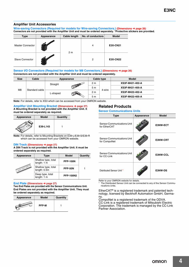
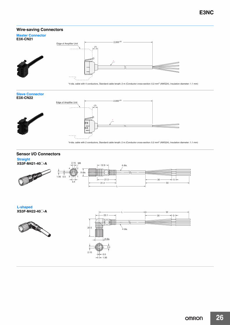
Amplifier Unit AccessoriesWire-saving Connectors (Required for models for Wire-saving Connectors.) (Dimensions ➜ page 26)Connectors are not provided with the Amplifier Unit and must be ordered separately. *Protective stickers are provided.
Sensor I/O Connectors (Required for models for M8 Connectors.) (Dimensions ➜ page 26)Connectors are not provided with the Amplifier Unit and must be ordered separately.
Note: For details, refer to XS3 which can be accessed from your OMRON website.
Amplifier Unit Mounting Bracket (Dimensions ➜ page 27)A Mounting Bracket is not provided with the Amplifier Unit. It must be ordered separately as required.
Note: For details, refer to Mounting Brackets on E39-L/E39-S/E39-R which can be accessed from your OMRON website.
DIN Track (Dimensions ➜ page 27)A DIN Track is not provided with the Amplifier Unit. It must be ordered separately as required.
End Plate (Dimensions ➜ page 27)Two End Plates are provided with the Sensor Communications Unit. End Plates are not provided with the Amplifier Unit. They must be ordered separately as required.
Related ProductsSensor Communications Units
Refer to your OMRON website for details.* The Distributed Sensor Unit can be connected to any of the Sensor Commu-
nications Units.
EtherCAT® is a registered trademark and patented tech-nology, licensed by Beckhoff Automation GmbH, Germa-ny.CompoNet is a registered trademark of the ODVA.CC-Link is a registered trademark of Mitsubishi Electric Corporation. The trademark is managed by the CC-Link Partner Association.
Type Appearance Cable length No. of conductors Model
Master Connector
2 m
4 E3X-CN21
Slave Connector 2 E3X-CN22
Size Cable Appearance Cable type Model
M8 Standard cable
2 m
4-wire
XS3F-M421-402-A
5 m XS3F-M421-405-A
2 m XS3F-M422-402-A
5 m XS3F-M422-405-A
Straight
L-shaped
Appearance Model Quantity
E39-L143 1
Appearance Type Model Quantity
Shallow type, total length: 1 m PFP-100N
1Shallow type, total length: 0.5m PFP-50N
Deep type, total length: 1 m PFP-100N2
Appearance Model Quantity
PFP-M 1
Type Appearance Model
Sensor Communications Unit for EtherCAT E3NW-ECT
Sensor Communications Unit for CompoNet E3NW-CRT
Sensor Communications Unit for CC-Link E3NW-CCL
Distributed Sensor Unit * E3NW-DS
5
E3NC
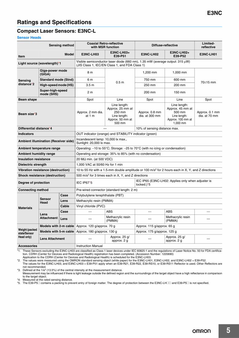
Ratings and SpecificationsCompact Laser Sensors: E3NC-LSensor Heads
*1. These Sensors excluding the E3NC-LH03 are classified as Class 1 laser devices under IEC 60825-1 and the regulations of Laser Notice No. 50 for FDA certifica-tion. CDRH (Center for Devices and Radiological Health) registration has been completed. (Accession Number: 1220690) Application to the CDRH (Center for Devices and Radiological Health) is scheduled for the E3NC-LH03.
*2. The values were measured using the OMRON standard sensing object (white paper) for the E3NC-LH01, E3NC-LH02, and E3NC-LH02 + E39-P52. The values for the E3NC-LH03, and E3NC-LH03 + E39-P51 apply when an E39-R21, E39-R22, E39-RS10, or E39-RS11 Reflector is used. Other Reflectors arenot recommended.
*3. Defined at the 1/e2 (13.5%) of the central intensity at the measurement distance.Measurement may be influenced if there is light leakage outside the defined region and the surroundings of the target object have a high reflectance in comparisonto the target object.
*4. Measured at the rated sensing distance.*5. The E39-P5@ contains a packing to prevent entry of foreign matter. The degree of protection between the E3NC-LH@@ and E39-P5@ is not specified.
Sensing method Coaxial Retro-reflective with MSR function Diffuse-reflective Limited-
reflective
ItemModel E3NC-LH03 E3NC-LH03+
E39-P51 E3NC-LH02 E3NC-LH02+E39-P52 E3NC-LH01
Light source (wavelength)*1 Visible semiconductor laser diode (660 nm), 1.35 mW (average output: 315 μW)(JIS Class 1, IEC/EN Class 1, and FDA Class 1)
Sensing distance*2
Giga-power mode (GIGA) 8 m
0.5 m
1,200 mm 1,000 mm
70±15 mmStandard mode (Stnd) 6 m 750 mm 600 mm
High-speed mode (HS) 3.5 m 250 mm 200 mm
Super-high-speed mode (SHS) 2 m 200 mm 150 mm
Beam shape Spot Line Spot Line Spot
Beam size*3 Approx. 2 mm dia. at 1 m
Line length: Approx. 25 mm at
250 mmLine length:
Approx. 50 mm at 500 mm
Approx. 0.8 mm dia. at 300 mm
Line length: Approx. 45 mm at
500 mmLine length:
Approx. 100 mm at 1,000 mm
Approx. 0.1 mm dia. at 70 mm
Differential distance*4 --- 10% of sensing distance max.
Indicators OUT indicator (orange) and STABILITY indicator (green)
Ambient illumination (Receiver side) Incandescent lamp: 10,000 lx max., Sunlight: 20,000 lx max.
Ambient temperature range Operating: −10 to 55°C; Storage: −25 to 70°C (with no icing or condensation)
Ambient humidity range Operating and storage: 35% to 85% (with no condensation)
Insulation resistance 20 MΩ min. (at 500 VDC)
Dielectric strength 1,000 VAC at 50/60 Hz for 1 min
Vibration resistance (destruction) 10 to 55 Hz with a 1.5-mm double amplitude or 100 m/s2 for 2 hours each in X, Y, and Z directions
Shock resistance (destruction) 500 m/s2 for 3 times each in X, Y, and Z directions
Degree of protection IEC IP67*5 IEC IP65 (E3NC-LH02: Applies only when adjuster is locked.)*5
Connecting method Pre-wired connector (standard length: 2 m)
Materials
Sensor Head
Case Polybutylene terephthalate (PBT)
Lens Methacrylic resin (PMMA)
Cable Vinyl chloride (PVC)
Lens Attachment
Case --- ABS --- ABS ---
Lens --- Methacrylic resin (PMMA) --- Methacrylic resin
(PMMA) ---
Weight (packed state/Sensor Head only)
Models with 2-m cable Approx. 120 g/approx. 70 g Approx. 115 g/approx. 65 g
Models with 5-m cable Approx. 180 g/approx. 130 g Approx. 175 g/approx. 125 g
Lens Attachment --- Approx. 25 g/approx. 2 g --- Approx. 25 g/
approx. 2 g ---
Accessories Instruction Manual

6
E3NC
Amplifier Units
*1. Two sensor outputs are allocated in the programmable logic controller PLC I/O table.PLC operation via Communications Unit enables reading detected values and changing settings.
*2. At Power Supply Voltage of 10 to 30 VDC. Normal mode: 1,650 mW max. (Current consumption: 55 mA max. at 30 VDC, 115 mA max. at 10 VDC) Power saving eco mode: 1,350 mW max. (Current consumption: 45 mA max. at 30 VDC, 80 mA max. at 10 VDC)
*3. The total for both outputs of a model with 2 outputs is 100 mA max. (Residual voltage: Load current of less than 10 mA: 1 V max., Load current of 10 to 100 mA:2 V max.).
*4. The following details apply to the input.
*4-1.Input time is 25 ms (ON)/(OFF) only when (in tUnE) or (in PtUn) input is selected.*5. The mutual interference prevention function is disabled if the detection mode is set to super-high-speed mode.*6. The bank is not reset by the user reset function or saved by the user save function.
Type Standard modelsModel for Sensor
Communications Unit
NPN output E3NC-LA21 E3NC-LA7 E3NC-LA24E3NC-LA0
PNP output E3NC-LA51 E3NC-LA9 E3NC-LA54
ItemConnecting method Pre-wired Wire-saving Connector M8 Connector
Connector for Sensor Communications Unit
Inputs/outputs
Outputs 2 outputs 1 output--- *1
External inputs 1 input
Power supply voltage 10 to 30 VDC, including 10% ripple (p-p)Supplied from the connector through the Sensor Communications Unit
Power consumption *2At Power Supply Voltage of 24 VDCNormal mode: 1,560mW max. (Current consumption: 65mA max.) Power saving eco mode: 1,200 mW max. (Current consumption: 50 mA max.)
Control outputs*3
Load power supply voltage: 30 VDC max., open-collector outputLoad current: Groups of 1 to 3 Amplifier Units: 100 mA max., Groups of 4 to 30 Amplifier Units: 20 mA max.
OFF current: 0.1 mA max.
---
External inputs Refer to *4. ---
Indicators
7-segment displays (Sub digital display: green, Main digital display: white)Display direction: Switchable between normal and reversed.OUT indicator (orange), L/D indicator (orange), ST indicator (blue), DPC indicator (green), and OUT selection indicator (orange, only on models with 2 outputs)
Protection circuits Power supply reverse polarity protection, output short-circuit protection, and output reverse polarity protection
Power supply reverse polarity protection and output short-circuit protection
Response time
Super-high-speed mode (SHS)*5 Operate or reset: 80 μs
High-speed mode (HS) Operate or reset: 250 μs
Standard mode (Stnd) Operate or reset: 1 ms
Giga-power mode (GIGA) Operate or reset: 16 ms
Sensitivity adjustment Smart Tuning (2-point tuning, full auto tuning, position tuning, maximum sensitivity tuning, power tuning, or percentage tuning (−99% to +99%)), or manual adjustment.
Maximum connectable Units 30
No. of Units for mutual interference prevention
Super-high-speed mode (SHS)*5 0
High-speed mode (HS) 2
Standard mode (Stnd) 2
Giga-power mode (GIGA) 4
Functions
Dynamic power control (DPC) Provided
Timer Select from timer disabled, OFF-delay, ON-delay, one-shot, or ON-delay + OFF-delay timer: 1 to 9,999 ms
Zero reset Negative values can be displayed. (Threshold value is shifted.)
Resetting settings*6 Select from initial reset (factory defaults) or user reset (saved settings).
Eco mode Select from OFF (digital displays lit) or ECO (digital displays not lit).
Bank switching Select from banks 1 to 4.
Power tuning Select from ON or OFF.
Output 1 Select from Normal Detection Mode or Area Detection Mode.
Output 2
Select from normal detection mode, alarm output mode, or error output mode.
---
Select from normal detection mode, alarm output mode, or error output mode.
External input Select from input OFF, tuning, power tuning, laser OFF, zero reset, or bank switching. ---
Hysteresis width Select from standard setting or user setting.
Contact input (relay or switch) Non-contact input (transistor) Input time*4-1
NPN ON: Shorted to 0 V (Sourcing current: 1 mA max.).OFF: Open or shorted to Vcc.
ON: 1.5 V max. (Sourcing current: 1 mA max.)OFF: Vcc − 1.5 V to Vcc (Leakage current: 0.1 mA max.) ON: 9 ms min.
OFF: 20 ms min.PNP ON: Shorted to Vcc (Sinking current: 3 mA max.).
OFF: Open or shorted to 0 V.ON: Vcc − 1.5 V to Vcc (Sinking current: 3 mA max.)OFF: 1.5 V max. (Leakage current: 0.1 mA max.)
Residual voltage: At load current of less than 10 mA: 1 V max.At load current of 10 to 100 mA: 2 V max.

E3NC
7
AccessoriesReflectors
Type Standard modelsModel for Sensor
Communications Unit
NPN output E3NC-LA21 E3NC-LA7 E3NC-LA24E3NC-LA0
PNP output E3NC-LA51 E3NC-LA9 E3NC-LA54
ItemConnecting
methodPre-wired Wire-saving Connector M8 Connector
Connector for Sensor Communications Unit
Ambient temperature range
Operating: Groups of 1 or 2 Amplifier Units: −25 to 55°C,Groups of 3 to 10 Amplifier Units: −25 to 50°C,Groups of 11 to 16 Amplifier Units: −25 to 45°C,Groups of 17 to 30 Amplifier Units: −25 to 40°CStorage: −30 to 70°C (with no icing or condensation)
Operating:Groups of 1 or 2 Amplifier Units: 0 to 55°C,Groups of 3 to 10 Amplifier Units: 0 to 50°C,Groups of 11 to 16 Amplifier Units: 0 to 45°C,Groups of 17 to 30 Amplifier Units: 0 to 40°C,Storage: −30 to 70°C (with no icing or condensation)
Ambient humidity range Operating and storage: 35% to 85% (with no condensation)
Insulation resistance 20 MΩ (at 500 VDC)
Dielectric strength 1,000 VAC at 50/60 Hz for 1 min
Vibration resistance (destruction) 10 to 55 Hz with a 1.5-mm double amplitude for 2 hours each in X, Y, and Z directions
Shock resistance (destruction) 500 m/s2 for 3 times each in X, Y, and Z directions 150m/s2 for 3 times each in X, Y, and Z directions
Weight (packed state/Amplifier Unit only) Approx. 115 g/approx. 75 g Approx. 60 g/approx. 20 g Approx. 65 g/approx. 25 g
Materials
Case Polycarbonate (PC)
Cover Polycarbonate (PC)
Cable Vinyl chloride (PVC)
Accessories Instruction Manual
Item Model E39-R21 E39-R22 E39-RS10 E39-RS11Ambient temperature Operating: -10 to 55°C; Storage: -25 to 70°C (with no icing or condensation)Ambient humidity Operating/storage: 35% to 85% (with no condensation)Vibration resistance (destruction) 10 to 55 Hz with a 1.5-mm double amplitude or 100 m/s2 for 2 hours each in X, Y, and Z directionsShock resistance (destruction) 500 m/s2 3 times each in X, Y, and Z directions
Degree of protection IEC IP67 (E39-R21 and E39-R22 only)
Materials Reflective surface: Methacrylic resin (PMMA)Back surface: Polybutylene terephthalate (PBT) Methacrylic resin (PMMA)
Weight (packed state/Reflector only) Approx. 30 g/approx. 5 g Approx. 35 g/approx. 10 g Approx. 26 g/approx. 1 g Approx. 30 g/approx. 5 g
Accessories Instruction manual

8
E3NC
Ultra-compact CMOS Laser Sensor: E3NC-SSensor Heads
Note: Incorrect detection may occur outside the measurement range if the object has a high reflection factor.*1. These Sensors are classified as Class 1 laser devices under IEC 60825-1 and the regulations of Laser Notice No. 50 for FDA certification. CDRH (Center for De-
vices and Radiological Health) registration has been completed. (Accession Number: 1220691)*2. The values were measured at the center of the sensing distance using OMRON’s standard sensing object (white ceramic).*3. Beam size: Defined at the 1/e2 (13.5 %) of the central intensity at the measurement center distance.
Measurement may be influenced if there is light leakage outside the defined region and the surroundings of the target object have a high reflectance in comparisonto the target object.Also, when detecting a workpiece that is smaller than the beam size, a correct value may not be obtained.
Sensing method Distance-settable
Item Model E3NC-SH250H E3NC-SH250 E3NC-SH100
Light source (wavelength)*1
Visible semiconductor laser diode (660 nm), 1 mW (average output: 220 μW) (JIS Class 2, IEC/EN Class 2, and FDA Class 2)
Visible semiconductor laser diode (660 nm), 0.5 mW (average output: 100 μW) (JIS Class 1, IEC/EN Class 1, and FDA Class 1)
Measurement range 35 to 250 mm (display value: 350 to 2,500) 35 to 100 mm (display value: 350 to 1,000)
Standard detected level difference *2
35 to 180mm: 9 mm180 to 250 mm: 25 mm
35 to 50 mm: 1.5 mm50 to 100 mm: 3 mm
Beam size*3 Approx. 1 mm dia. at 250 mm Approx. 0.5 mm dia. at 100 mm
Indicators OUT indicator (orange), STABILITY indicator (green), and ST indicator (blue)
Ambient illumination(Receiver side)
Incandescent lamp: 4,000 lx max., Sunlight: 8,000 lx max.
Incandescent lamp: 2,000 lx max., Sunlight: 4,000 lx max.
Incandescent lamp: 4,000 lx max., Sunlight: 8,000 lx max.
Ambient temperature range Operating: −10 to 50°C; Storage: −25 to 70°C (with no icing or condensation)
Ambient humidity range Operating and storage: 35% to 85% (with no condensation)
Insulation resistance 20 MΩ min. (at 500 VDC)
Dielectric strength 1,000 VAC at 50/60 Hz for 1 min
Vibration resistance (destruction) 10 to 55 Hz with a 1.5-mm double amplitude for 2 hours each in X, Y, and Z directions
Shock resistance (destruction) 500 m/s2 3 times each in X, Y, and Z directions
Degree of protection IEC IP67
Connecting method Pre-wired connector (Standard cable length: 2 m)
Materials
Case Polybutylene terephthalate (PBT)
Lens Methacrylic resin (PMMA)
Cable Vinyl chloride (PVC)
Weight (packed state/Sensor Head only) Approx. 125 g/approx. 75 g
Accessories Instruction Manual, laser warning label (E3NC-SH250H only)

E3NC
9
Amplifier Units
*1. Two sensor outputs are allocated in the programmable logic controller PLC I/O table.PLC operation via Communications Unit enables reading detected values and changing settings.
*2. At Power Supply Voltage of 10 to 30 VDC. Normal mode: 2,250 mW max. (Current consumption: 75 mA max. at 30 VDC, 145 mA max. at 10 VDC) Power saving eco mode: 1,950 mW max. (Current consumption: 65 mA max. at 30 VDC, 125 mA max. at 10 VDC)
*3. The total for both outputs of a model with 2 outputs is 100 mA max. (Residual voltage: Load current of less than 10 mA: 1 V max., Load current of 10 to 100 mA:2 V max.).
*4. The following details apply to the input.
*4-1.Input time is 25 ms (ON)/(OFF) only when (in tUnE) input is selected.*5. The mutual interference prevention function is disabled if the detection mode is set to super-high-speed mode.*6. The bank is not reset by the user reset function or saved by the user save function.*7. The output for a measurement error is set. ON: The value of the output from before the measurement error is retained. OFF: The output is turned OFF when a
measurement error occurs.*8. Only the sensing object is detected when tuning.
Type Standard models Model for Sensor Communications Unit
NPN output E3NC-SA21 E3NC-SA7 E3NC-SA24E3NC-SA0
PNP output E3NC-SA51 E3NC-SA9 E3NC-SA54
Item Connecting method Pre-wired Wire-saving Connector M8 Connector Connector for Sensor Communications Unit
Inputs/outputs
Outputs 2 outputs 1 output--- *1
External inputs 1 input
Power supply voltage 10 to 30 VDC, including 10% ripple (p-p)Supplied from the connector through the Sensor Communications Unit
Power consumption *2At Power Supply Voltage of 24 VDC
Normal mode: 1,920 mW max. (Current consumption: 80 mA max.)Power saving eco mode: 1,680 mW max. (Current consumption: 70 mA max.)
Control outputs *3
Load power supply voltage: 30 VDC max., open-collector outputLoad current: Groups of 1 to 3 Amplifier Units: 100 mA max., Groups of 4 to 30 Amplifier Units: 20 mA max.
OFF current: 0.1 mA max.
---
External inputs Refer to *4.
Indicators
7-segment displays (Sub digital display: green, Main digital display: white)Display direction: Switchable between normal and reversed.OUT indicator (orange), L/D indicator (orange), ST indicator (blue), ZERO indicator (green), and OUT selection indicator (orange, only on models with 2 outputs)
Protection circuitsPower supply reverse polarity protection, output short-circuit protection, and output reverse polarity protection
Power supply reverse polarity protection and output short-circuit protection
Response time
Super-high-speed mode (SHS) *5 Operate or reset: 1.5 ms
High-speed mode (HS) Operate or reset: 5 ms
Standard mode (Stnd) Operate or reset: 10 ms
Giga-power mode (GIGA) Operate or reset: 50 ms
Sensitivity adjustmentSmart Tuning(2-point tuning, full auto tuning, 1-point tuning, tuning without workpiece, 2-point area tuning, 1-point area tuning, or area tuning without workpiece), or manual adjustment
Maximum connectable Units 30
No. of Units for mutual interference prevention
Super-high-speed mode (SHS) *5 0
High-speed mode (HS) 2
Standard mode (Stnd) 2
Giga-power mode (GIGA) 2
Functions
Timer Select from timer disabled, OFF-delay, ON-delay, one-shot, or ON-delay + OFF-delay timer: 1 to 9,999 ms
Zero reset Negative values can be displayed. (Threshold value is shifted.)
Resetting settings *6 Select from initial reset (factory defaults) or user reset (saved settings).
Eco mode Select from OFF (digital displays lit) or ECO (digital displays not lit).
Bank switching Select from banks 1 to 4.
Output 1 Select from Normal detection mode, Area detection mode, or hold mode.
Output 2Select from Normal detection mode or Error output mode.
---Select from Normal detection mode or Error output mode.
External input Select from input OFF, tuning, laser OFF, zero reset, or bank switching. ---
Keep function *7 Select from ON or OFF.
Background suppression*8 Select from ON or OFF.
Hysteresis width Select from standard setting or user setting.
Contact input (relay or switch) Non-contact input (transistor) Input time*4-1
NPN ON: Shorted to 0 V (Sourcing current: 1 mA max.).OFF: Open or shorted to Vcc.
ON: 1.5 V max. (Sourcing current: 1 mA max.)OFF: Vcc − 1.5 V to Vcc (Leakage current: 0.1 mA max.) ON: 9 ms min.
OFF: 20 ms min.PNP ON: Shorted to Vcc (Sinking current: 3 mA max.).
OFF: Open or shorted to 0 V.ON: Vcc − 1.5 V to Vcc (Sinking current: 3 mA max.)OFF: 1.5 V max. (Leakage current: 0.1 mA max.)
Residual voltage: At load current of less than 10 mA: 1 V max.At load current of 10 to 100 mA: 2 V max.

10
E3NC
Type Standard models Model for Sensor Communications Unit
NPN output E3NC-SA21 E3NC-SA7 E3NC-SA24E3NC-SA0
PNP output E3NC-SA51 E3NC-SA9 E3NC-SA54
Item Connecting method Pre-wired Wire-saving Connector M8 Connector Connector for Sensor
Communications Unit
Ambient temperature range
Operating:Groups of 1 or 2 Amplifier Units: −25 to 55°C,Groups of 3 to 10 Amplifier Units: −25 to 50°C,Groups of 11 to 16 Amplifier Units: −25 to 45°C,Groups of 17 to 30 Amplifier Units: −25 to 40°CStorage: −30 to 70°C (with no icing or condensation)
Operating:Groups of 1 or 2 Amplifier Units: 0 to 55°C,Groups of 3 to 10 Amplifier Units: 0 to 50°C,Groups of 11 to 16 Amplifier Units: 0 to 45°C,Groups of 17 to 30 Amplifier Units: 0 to 40°CStorage: −30 to 70°C (with no icing or condensation)
Ambient humidity range Operating and storage: 35% to 85% (with no condensation)
Insulation resistance 20 MΩ (at 500 VDC)
Dielectric strength 1,000 VAC at 50/60 Hz for 1 min
Vibration resistance (destruction) 10 to 55 Hz with a 1.5-mm double amplitude for 2 hours each in X, Y, and Z directions
Shock resistance (destruction) 500 m/s2 for 3 times each in X, Y, and Z directions 150 m/s2 for 3 times each in X, Y, and Z directions
Weight (packed state/Amplifier Unit only) Approx. 115 g/approx. 75 g Approx. 60 g/approx. 20 g Approx. 65 g/approx. 25 g
Materials
Case Polycarbonate (PC)
Cover Polycarbonate (PC)
Cable Vinyl chloride (PVC)
Accessories Instruction Manual
11
E3NC
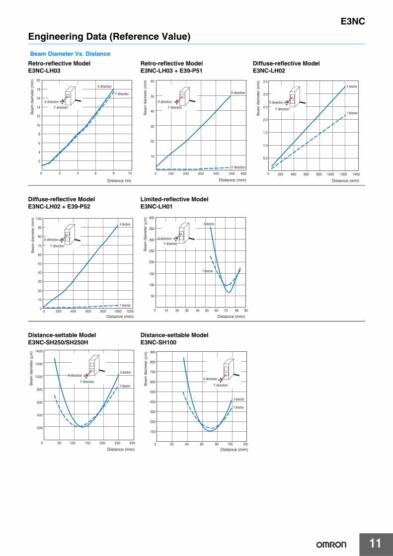
Engineering Data (Reference Value)
Beam Diameter Vs. Distance
Retro-reflective Model E3NC-LH03
Retro-reflective Model E3NC-LH03 + E39-P51
Diffuse-reflective Model E3NC-LH02
Diffuse-reflective Model E3NC-LH02 + E39-P52
Limited-reflective Model E3NC-LH01
Distance-settable Model E3NC-SH250/SH250H
Distance-settable Model E3NC-SH100
2
4
6
8
10
12
14
16
18
20
0 2 4 6 8 10
X direction
Y direction
X direction
Y direction
Distance (m)
Bea
m d
iam
eter
(m
m)
10
20
30
40
50
60
0 100 200 300 400 500 600
X direction
Y direction
X direction
Y direction
Distance (mm)
Bea
m d
iam
eter
(m
m)
0
0.5
1.0
1.5
2.0
2.5
3.0
3.5
200 400 600 800 1000 1200 1400
X direction
Y direction
X direction
Y direction
Distance (mm)
Bea
m d
iam
eter
(m
m)
0
10
20
30
40
50
60
70
80
90
100
0 200 400 600 800 1000 1200
X direction
Y direction
X direction
Y direction
Distance (mm)
Bea
m d
iam
eter
(m
m)
0
50
100
150
200
350
250
300
400
10 3020 5040 60 70 80 90
X direction
Y direction
X directionY direction
Distance (mm)
Bea
m d
iam
eter
(μm
)
0
200
400
600
800
1000
1200
1400
50 100 150 200 250 300
X direction
Y direction
X direction
Y direction
Distance (mm)
Bea
m d
iam
eter
(μm
)
100
200
300
400
500
600
700
800
900
0 20 40 60 80 100 120
X direction
Y direction
X direction
Y direction
Distance (mm)
Bea
m d
iam
eter
(μm
)

E3NC
12
I/O Circuit DiagramsNPN Output
PNP Output
Model Operation mode Timing chart L/D indicator Output circuit
E3NC-LA21E3NC-SA21
Light-ON
Dark-ON
E3NC-LA7E3NC-LA24E3NC-SA7E3NC-SA24
Light-ON
Dark-ON
Model Operation mode Timing chart L/D indicator Output circuit
E3NC-LA51E3NC-SA51
Light-ON
Dark-ON
E3NC-LA9E3NC-LA54E3NC-SA9E3NC-SA54
Light-ON
Dark-ON
Incident lightNo incident light
LitNot lit
ONOFF
OperateReset
OUT indicator(orange)OutputtransistorLoad(e.g., relay)
(Between brown and black (orange) leads)
ch1/ch2
lit.L
Load
Load
OUT2 indicator(orange) Brown
Black
Control outputch1
Control outputch2
External input
Orange
Blue
Pink
10 to 30 VDC
OUT1 indicator(orange)
Display
Photoelectric sensor main
circuitIncident lightNo incident light
LitNot lit
ONOFF
OperateReset
OUT indicator(orange)OutputtransistorLoad(e.g., relay)
(Between brown and black (orange) leads)
ch1/ch2
lit.D
Incident lightNo incident light
LitNot lit
ONOFF
OperateReset
OUT indicator(orange)OutputtransistorLoad(e.g., relay)
(Between brown and black leads)
lit.L1
4
2
3
Load
Brown
Black
Control output
External inputBlue
Orange
10 to 30 VDC
OUT indicator(orange)
Display
Photoelectric sensor main
circuitIncident lightNo incident light
LitNot lit
ONOFF
OperateReset
OUT indicator(orange)OutputtransistorLoad(e.g., relay)
(Between brown and black leads)
lit.D
Incident lightNo incident light
LitNot lit
ONOFF
OperateReset
OUT indicator(orange)OutputtransistorLoad(e.g., relay)
(Between blue and black (orange) leads)
ch1/ch2
lit.L
Photoelectric sensor main
circuitLoad
Load
OUT2 indicator (orange)
Control output ch2
Control output ch1
Brown
Black
Pink
Orange
Blue
10 to 30 VDC
OUT1 indicator (orange)
Display
External input
Incident lightNo incident light
LitNot lit
ONOFF
OperateReset
OUT indicator(orange)OutputtransistorLoad(e.g., relay)
(Between blue and black (orange) leads)
ch1/ch2
lit.D
Incident lightNo incident light
LitNot lit
ONOFF
OperateReset
OUT indicator(orange)OutputtransistorLoad(e.g., relay)
(Between blue and black leads)
lit.L1
2
4
3
Photoelectric sensor main
circuitLoad
Control output
Brown
Black
Orange
Blue
10 to 30 VDC
OUT indicator (orange)
Display
External input
Incident lightNo incident light
LitNot lit
ONOFF
OperateReset
OUT indicator(orange)OutputtransistorLoad(e.g., relay)
(Between blue and black leads)
lit.D

E3NC
13
NomenclatureCompact Laser SensorsE3NC-LA21/LA51/LA0 E3NC-LA7/LA9/LA24/LA54
Ultra-compact CMOS Laser SensorsE3NC-SA21/SA51/SA0 E3NC-SA7/SA9/SA24/SA54
[OUT1 Indicator/OUT2 Indicator]
Turns ON when OUT1 or OUT2 is ON.
[OUT1 Selection Indicator/OUT2 Selection Indicator]
The indicator for the selected output channel is lit.
[L/D Indicator]Indicates the setting status: Light-ON (L) or Dark-ON (D).
Executes Smart Tuning.[ Tune Button]
[ L/D Button]Used to switch between Light-ON (L) and Dark-ON (D).
Incident LevelWhite digital display
[+−UP/DOWN Button] Used to fine-tune the threshold or change set values.
Threshold LevelGreen digital display
[DPC Indicator] Turns ON when Dynamic Power Control is effective.
[ST Indicator] Turns ON when Smart Tuning is in progress.
[ MODE Button]Used to switch between Detection Mode and Setting Mode, and used to switch between OUT1 and OUT2.
[L/D Indicator]Indicates the setting status: Light-ON (L) or Dark-ON (D).
Executes Smart Tuning.[ Tune Button]
[ L/D Button]Used to switch between Light-ON (L) and Dark-ON (D).[OUT Indicator]
Turns ON when the output is ON.
Incident LevelWhite digital display
[+−UP/DOWN Button] Used to fine-tune the threshold or change set values.
[ MODE Button]Used to switch between Detection Mode and Setting Mode.
Threshold LevelGreen digital display
[DPC Indicator] Turns ON when Dynamic Power control is effective.
[ST Indicator] Turns ON when Smart Tuning is in progress.
[ZERO Indicator]Turns ON while a zero reset is set.
[OUT1 Indicator/OUT2 Indicator]Turns ON when OUT1 or OUT2 is ON.
Measurement Value White digital display
[OUT1 Selection Indicator/OUT2 Selection Indicator]The indicator for the selected output channel is lit.
[L/D Indicator]Indicates the setting status: Light-ON (L) or Dark-ON (D).
Threshold LevelGreen digital display
Executes Smart Tuning.
[ Tune Button]
[ L/D Button]Used to switch between Light-ON (L) and Dark-ON (D).
[+−UP/DOWN Button] Used to fine-tune the threshold or change set values.
[ST Indicator] Turns ON when Smart Tuning is in progress.
[ MODE Button]Used to switch between DetectionMode and Setting Mode, and used to switch between OUT1 and OUT2.
[ZERO Indicator]Turns ON while a zero reset is set.
Measurement Value White digital display
[L/D Indicator]Indicates the setting status: Light-ON (L) or Dark-ON (D).
Threshold LevelGreen digital display
Executes Smart Tuning.[ Tune Button]
[ L/D Button]Used to switch between Light-ON (L) and Dark-ON (D).
[OUT Indicator]Turns ON when the output is ON.
[+−UP/DOWN Button] Used to fine-tune the threshold or change set values.
[ MODE Button]Used to switch between Detection Mode and Setting Mode.
[ST Indicator] Turns ON when Smart Tuning is in progress.

14
E3NC
Safety PrecautionsTo ensure safe operation, be sure to read and follow the Instruction Manual provided with the Sensor.
Indication and Meaning for Safe Use
Sensor Heads
Various safety standards regarding laser devices are stipulated in Japan and abroad. When this Sensor Head is used in Japan and when it is assembled in Japan but exported to a foreign country, the safety standards are classified into three cases.1. When Using the Sensor Head in Japan
JIS C6802 stipulates the safety measures that must be observed by the user for each type of laser equipment.
E3NC-LH@@ Sensor Heads: Class 1E3NC-SH@@ Sensor Heads: Class 1E3NC-SH@@H Sensor Heads: Class 2
• The following laser warning label and laser description labels are attached to the sides of the Sensor Heads.E3NC-LH03
E3NC-LH01
/E3NC-LH02
E3NC-SH@@
E3NC-SH@@H
2. Using in the USAWhen using devices in which the Sensor Head is installed in the USA, the devices are subject to FDA (Food and Drug Administration) laser regulations of the USA.
E3NC-LH03:These Sensor Heads are classified as Class 1 laser devices under IEC/EN 60825-1 and the regulations of Laser Notice No. 50 for this certification. Application to the CDRH (Center for Devices and Radiological Health) is scheduled.
E3NC-LH01, E3NC-LH02:These Sensor Heads are classified as Class 1 laser devices under IEC/EN 60825-1 and the regulations of Laser Notice No. 50 for this certification. CDRH (Center for Devices and Radiological Health) registration has been completed. (Accession Number: 1220690)
E3NC-SH@@, E3NC-SH@@H:These Sensor Heads are classified as Class 1 or Class 2 laser devices under IEC/EN 60825-1 and the regulations of Laser Notice No. 50 for this certification. CDRH (Center for Devices and Radiological Health) registration has been completed. (Accession Number: 1220691)
• For countries other than JapanReplace the warning label with the corresponding English label (supplied with SH@@H).
3. Using in EuropeE3NC-LH@@, E3NC-SH@@:These Sensor Heads are classified in Class 1 under EN 60825-1.E3NC-SH@@H:These Sensor Heads are classified in Class 2 under EN 60825-1.
Indicates a potentially hazardous situation which, if not avoided, will result in minor or moderate injury, or may result in serious injury or death. Additionally there may be significant property damage.
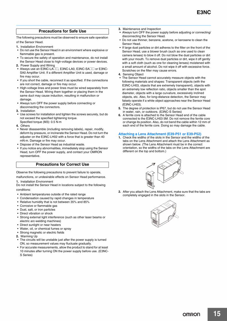
Precautions for Safe Use
Supplementary comments on what to do or avoid doing, to use the product safely.
Precautions for Correct Use
Supplementary comments on what to do or avoid doing, to prevent failure to operate, malfunction or undesirable effect on product performance.
WARNING
Laser Safety
WARNINGDo not expose your eyes to the laser beam either directly or indirectly (i.e., after reflection from a mirror or shiny surface). The laser beam has a high power density and exposure may result in loss of sight.
Do not disassemble the Sensor Head. Doing so may cause the laser beam to leak, resulting in a risk of visual impairment.
Certification Label
Class1LASERPRODUCT
Description Label
Certification Label
Class1LASERPRODUCT
Description Label
Certification Label
Class1LASERPRODUCT
Description Label
Laser Warning Label Certification Label
E3NC
15
The following precautions must be observed to ensure safe operation
of the Sensor Head.
1. Installation Environment• Do not use the Sensor Head in an environment where explosive or
flammable gas is present.• To secure the safety of operation and maintenance, do not install
the Sensor Head close to high-voltage devices or power devices.2. Power Supply and Wiring• Always use an E3NC-LA@@, E3NC-LA0, E3NC-SA@@ or E3NC-
SA0 Amplifier Unit. If a different Amplifier Unit is used, damage or fire may occur.
• If you short the cable, reconnect it as specified. If the connections are not correct, damage or fire may occur.
• High-voltage lines and power lines must be wired separately from the Sensor Head. Wiring them together or placing them in the same duct may cause induction, resulting in malfunction or damage.
• Always turn OFF the power supply before connecting or disconnecting the connectors.
3. Installation• Use screws for installation and tighten the screws securely, but do
not exceed the specified tightening torque.Specified torque (M3): 0.5 N·m
4. Others• Never disassemble (including removing labels), repair, modify,
deform by pressure, or incinerate the Sensor Head. Do not turn the adjuster on the E3NC-LH02 with a force that is greater than 40 mN·m. Damage or fire may occur.
• Dispose of the Sensor Head as industrial waste.• If you notice any abnormalities, immediately stop using the Sensor
Head, turn OFF the power supply, and contact your OMRON representative.
Observe the following precautions to prevent failure to operate,
malfunctions, or undesirable effects on Sensor Head performance.
1. Installation EnvironmentDo not install the Sensor Head in locations subject to the following
conditions:
• Ambient temperatures outside of the rated range• Condensation caused by rapid changes in temperature• Relative humidity that is not between 35% and 85%• Corrosive or flammable gas• Dust, salt, or iron particles• Direct vibration or shock• Strong external light interference (such as other laser beams or
electric arc-welding machines)• Direct sunlight or near heaters• Water, oil, or chemical fumes or spray• Strong magnetic or electric fields
2. Warming Up• The circuits will be unstable just after the power supply is turned
ON, so measurement values may fluctuate gradually.• For accurate measurements, allow the product to stand for at least
10 minutes after turning ON the power supply before use. (E3NC-S Series)
3. Maintenance and Inspection• Always turn OFF the power supply before adjusting or connecting/
disconnecting the Sensor Head.• Do not use thinner, benzene, acetone, or kerosene to clean the
Sensor Head.• If large dust particles or dirt adheres to the filter on the front of the
Sensor Head, use a blower brush (such as one used to clean camera lenses) to blow it off. Do not blow the dust particles or dirt with your mouth. To remove dust particles or dirt, wipe it off gently with a soft cloth (such as one for cleaning lenses) moistened with a small amount of alcohol. Do not wipe it off with excessive force. Scratches on the filter may cause errors.
4. Sensing Object• The Sensor Head cannot accurately measure objects with the
following materials and shapes: Transparent objects (with the E3NC-LH03, objects that are extremely transparent), objects with an extremely low reflection ratio, objects smaller than the spot diameter, objects with a large curvature, excessively inclined objects, etc. Also, for long-distance detection, the Sensor may falsely operate if a white object approaches near the Sensor Head (E3NC-LH03).
5. The degree of protection is IP67, but do not use the Sensor Head in water, rain, or outdoors. (E3NC-S Series)
6. A ferrite core is attached to the Sensor Head end of the cable connected to the E3NC-LH03 5M. Do not remove the ferrite core or change its position. Also, do not bend the cable within 12 mm of each end of the ferrite core. Doing so may damage the cable.
Attaching a Lens Attachment (E39-P51 or E39-P52)1. Check the widths of the slots in the Sensor and the widths of the
tabs on the Lens Attachment and attach the Lens Attachment as shown below. (The Lens Attachment must be in the correct orientation, so the widths of the tabs on the Lens Attachment are different on the top and bottom.)
2. After you attach the Lens Attachment, make sure that the tabs are completely engaged in the slots in the Sensor.
Precautions for Safe Use
Precautions for Correct Use

16
E3NC
Amplifier Units
This Amplifier Unit is not designed or rated for ensuring safety of persons either directly or indirectly.Do not use it for such purposes.
Do not use the Amplifier Unit with voltage in excess of the rated voltage.Excess voltage may result in malfunction or fire.
Never use the Amplifier Unit with an AC power supply.Otherwise, explosion may result.
The following precautions must be observed to ensure safe operation of the Amplifier Unit. Doing so may cause damage or fire.1. Do not install the Amplifier Unit in the following locations.• Locations subject to direct sunlight• Locations subject to condensation due to high humidity• Locations subject to corrosive gas• Locations subject to vibration or mechanical shocks exceeding the
rated values• Locations subject to exposure to water, oil, chemicals• Locations subject to steam• Locations subjected to strong magnetic field or electric field
2. Do not use the Amplifier Unit in environments subject to flammable or explosive gases.
3. Do not use the Amplifier Unit in any atmosphere or environment that exceeds the ratings.
4. To secure the safety of operation and maintenance, do not install the Amplifier Unit close to high-voltage devices or power devices.
5. High-voltage lines and power lines must be wired separately from the Amplifier Unit. Wiring them together or placing them in the same duct may cause induction, resulting in malfunction or damage.
6. Do not apply any load exceeding the ratings. Otherwise, damage or fire may result.
7. Do not short the load. Otherwise, damage or fire may result.8. Connect the load correctly.9. Do not miswire such as the polarity of the power supply.10.Do not use the Amplifier Unit if the case is damaged.11.Burn injury may occur. The Amplifier Unit surface temperature
rises depending on application conditions, such as the ambient temperature and the power supply voltage. Use caution when operating or cleaning the Amplifier Unit.
12.When setting the sensor, be sure to check safety such as by stopping the equipment.
13.Be sure to turn off the power supply before connecting or disconnecting wires.
14.Do not attempt to disassemble, repair, or modify the Amplifier Unit in any way.
15.When disposing of the Amplifier Unit, treat it as industrial waste.
1. Be sure to mount the unit to the DIN track until it clicks.2. When using the Amplifier Units with Wire-saving Connectors,
attach the protective stickers (provided with E3X-CN-series Connectors) on the unused power pins to prevent electrical shock and short circuiting. When using the Amplifier Units with Connectors for Communications Units, attach the protective caps (provided with E3NW-series Sensor Communications Unit).
3. Use an extension cable with a minimum thickness of 0.3 mm2 and less than 100 m long.
4. Do not apply the forces on the cord exceeding the following limits:Pull: 40 N; torque: 0.1 N·m; pressure: 20 N; bending: 29.4 N
5. Do not apply excessive force (9.8 N max.) such as tension, compression or torsion to the connector of the Sensor Head that is fixed to the Amplifier Unit.
6. Always keep the protective cover in place when using the Amplifier Unit. Not doing so may cause malfunction.
7. It may take time until the received light intensity and measured value become stable immediately after the power is turned on depending on use environment.
8. The product is ready to operate 200 ms after the power supply is turned ON.
9. The Mobile Console E3X-MC11, E3X-MC11-SV2 and E3X-MC11-S cannot be connected.
10.The mutual interference prevention function does not work when in combination with E3C/E2C/E3X.
11.If the unit receives excessive sensor light, the mutual interference prevention function may not work properly, resulting in malfunction of the unit. In such case, increase the threshold.
12.Standard models (E3NC-@A21/51/7/9)The Sensor Communications Unit E3X-DRT21-S, E3X-CRT, E3X-ECT and E3NW cannot be connected.Model for Sensor Communications Unit (E3NC-@A0)The Sensor Communications Unit E3NW can be connected.E3X-DRT21-S, E3X-CRT, E3X-ECT cannot be connected.
13.If you notice an abnormal condition such as a strange odor, extreme heating of the unit, or smoke immediately stop using the product, turn off the power, and consult your dealer.
14.Do not use thinner, benzene, acetone, and lamp oil for cleaning.
WARNING
Precautions for Safe Use
Precautions for Correct Use
Protective sticker
Power supply connecting terminals
Protective cap
Amplifier Unit with Wire-saving Connector
Amplifier Unit with Connector for Sensor Communications Unit

17
E3NC
DimensionsSensor Heads
(Unit: mm)Tolerance class IT16 applies to dimensions in this data sheet unless otherwise specified.
Mounting Holes
Vinyl-insulated CableTwo, 2.3-dia., 6 conductors (Conductor cross-section: 0.08 mm2, Insulation diameter: 0.38 mm),Standard cable length: 2 m, Minimum bending radius: 12 mm
6
Emission and reception axis6.2
3
2.9
OUT indicator
STABILITY indicator
12.412.4
3636
2525
12
21.5
27.5
10
23.5 9.5
6.6
Two, 3.2 dia. (mounting holes)
Emission and reception center
1.2
10
9.5±0.1
17±0.1
17 20
18
Connector
Two, M3 holes
Ferrite core*1
25
12.8
11.290±10
*1 A ferrite core is attached to the Sensor Head end of the cable attached to the E3NC-LH03 5M.
*2
*2 A blue ID tube is attached.
Retro-reflective ModelE3NC-LH03
Diffuse-reflective ModelE3NC-LH02
18
6
5.5
28.928.9
3333
9.9 16
27
3
15
27±0.05
16±0.05
8.5
11.53
10
12.2
12.318.5
3
3.5
11
6.23.6
8
12.412.4
Two, 3.2 dia. (mounting holes)(Adjuster locked: 32.4,
Unlocked: 33.7)
9 dia.
*
Two, M3 holes
Mounting Holes
Connector
Vinyl-insulated CableTwo, 2.3-dia., 6 conductors (Conductor cross-section: 0.08 mm2, Insulation diameter: 0.38 mm), Standard cable length: 2 m, Minimum bending radius: 12 mm
OUT indicator
Adjuster
STABILITY indicator
Emission axis
Reception center
Emission center
* A blue ID tube is attached.

18
E3NC
Limited-reflective ModelE3NC-LH01
14
12.412.4
34.5.53.2 38
8±0.05
45.8 18
11.5
26.826.8
6
8.5
18
12.3
16.9
18.5
11
2.7
6.2
6.2
3.6
8
Two, M3 holes3.2 dia. (mounting hole)
Mounting Holes
Connector
OUT indicatorEmission center
Emission axis
Reception center
16 to 20
STABILITYindicator
Vinyl-insulated CableTwo, 2.3-dia., 6 conductors (Conductor cross-section: 0.08 mm2, Insulation diameter: 0.38 mm), Standard cable length: 2 m, Minimum bending radius: 12 mm
*
* A blue ID tube is attached.
3.3
48
7
1313
16±0.05
28.828.8
4141
1.5
16
7
9.9
196.5
8.35
27±0.05
25.4±0.05
11
9.9
11.6
25.4
21.5
10.5
27
11.6
13.52
18
6
Mounting Holes
Connector
ST indicator
STABILITY indicator
OUT indicatorSmart Tuning Button
Emission center
Reception center
Three, M3 holes
Three, 3.2 dia. (mounting holes)
*1 E3NC-SH100L = 35 to 100 mm,A = 15.92° to 5.67°
E3NC-SH250H/250L = 35 to 250 mm,A = 15.92° to 2.27°
Vinyl-insulated Cable4-dia., 6 conductors (Conductor cross-section: 0.08 mm2, Insulation diameter: 0.38 mm), Standard cable length: 2 m, Minimum bending radius: 12 mm
*2
*2 A white ID tube is attached.
A° *1
L *1
Distance-settable ModelsE3NC-SH250HE3NC-SH250E3NC-SH100

19
E3NC
Amplifier Units
2.6
32.1
(49.5)
83.483.4(20.3)
12.7
33.533.5
1010
2.6
32.1 16(9.4)
(37)
83.483.4
4.3
12.7
33.533.5
16(41.5)
4.43.4
16
*3 *3
(37)
27.830.2Indicator *1
*2
L/D indicator
ST indicator
Threshold level (green, digital)
OUT2 indicatorOUT1 indicator
OUT1 selection indicator
OUT2 selection indicator
167.8 167.8 (max. value with cover open)
170° (max. value with cover open)
Optical communicationsTwo, 3.2 dia. (mounting holes)
114 114 (max. value with cover
open)
Two, M3 holes
E39-L143 Mounting Bracket(sold separately, SUS304)
PFP-@N DIN Track (sold separately)
Mounting Holes
With Mounting Bracket AttachedMounted to DIN Track
Optical communications
*1. The indicators are as follows:
E3NC-LA21E3NC-LA51 DPC indicator
E3NC-SA21E3NC-SA51 ZERO indicator
*2. The display is as follows:
E3NC-LA21E3NC-LA51
Incident level (white, digital)
E3NC-SA21E3NC-SA51
Measurement value (white, digital)
*3. Cable SpecificationsRound vinyl-insulated cable, 4 dia., 5 conductors(Conductor cross-section: 0.2 mm2, Insulation diameter: 0.9 mm),Standard cable length: 2 m, Minimum bending radius: 12 mm
Pre-wired Amplifier UnitsE3NC-LA21E3NC-LA51E3NC-SA21E3NC-SA51
1010
2.6
33.5
32.1
16 16
3.44.4
2.6
33.5
32.1 16
4.3
30.9 27.1
Wire-saving Connector (sold separately)
167.8 167.8 (max. value with cover open)
(37)
(49.5)
(86.9)(86.9)
(23.8)
(13)
170° (max. value with cover open)
Wire-saving Connector (sold separately)
Two, M3 holes
(41.5)
(37)
(9.4)
(86.9)(86.9)
(13)
Optical communications
Two, 3.2 dia. (mounting holes)
114 114 (max. value with cover
open)
L/D indicator
ST indicator
OUT indicator
Threshold level (green, digital)
PFP-@N DIN Track (sold separately)
Mounting Holes
With Mounting Bracket AttachedMounted to DIN Track
E39-L143 Mounting Bracket(sold separately, SUS304)
*3
Indicator *1
*2
*3
Optical communications
*3. Cable Specifications
Model Outer diameter No. of conductors
E3X-CN224.0
2
E3X-CN21 4
*1. The indicators are as follows:E3NC-LA7E3NC-LA9
DPC indicator
E3NC-SA7E3NC-SA9
ZERO indicator
*2. The display is as follows:E3NC-LA7E3NC-LA9
Incident level (white, digital)
E3NC-SA7E3NC-SA9
Measurement value (white, digital)
Amplifier Units with Wire-saving ConnectorsE3NC-LA7E3NC-LA9E3NC-SA7E3NC-SA9

20
E3NC
(20.3)
32.1
83.483.4
30.9 27.1
10
1
2
3
4
6.9
5.24.2
2.6(93.4)
3.4
4.9
16
4.4
16
2.6
33.53.4
16(9.4)
83.483.4
(20.5)
32.1
57.7
4.3
33.5
10
3.9
19.212.7
10
12.7
3.4
(49.5)
(41.5)
(37)
Mounted to DIN Track
Mounting Holes
With Mounting Bracket Attached
114 114 (max. value with cover
open)
167.8 167.8 (max. value with cover open)
170° (max. value with cover open)
PFP-@N DIN Track (sold separately)
M8 Connector
Two, 3.2 dia. (mounting holes)
Optical communications
L/D indicator
ST indicator
OUT indicator
Threshold level (green, digital)
Two, M3 holes
E39-L143 Mounting Bracket (sold separately, SUS304)
Connector pin arrangement
M8 ConnectorOptical communications
Indicator *1
*2
(37)
*1. The indicators are as follows:E3NC-LA24E3NC-LA54
DPC indicator
E3NC-SA24E3NC-SA54
ZERO indicator
*2. The display is as follows:E3NC-LA24E3NC-LA54
Incident level (white, digital)
E3NC-SA24E3NC-SA54
Measurement value (white, digital)
Amplifier Units with M8 ConnectorsE3NC-LA24E3NC-LA54E3NC-SA24E3NC-SA54
Amplifier Units with Connectors for Sensor Communications UnitE3NC-LA0E3NC-SA0
102.4102.4
2.6
30.2 27.8
1010
11.5
13.8
33.533.5
32.1
26
ST indicator
Threshold level (green, digital)
OUT2 indicator
OUT2 selection indicator
OUT1 selection indicator
OUT1 indicator
159.7 159.7 (max. value with cover open)152° (max. value with cover open)
Optical communications
L/D indicator
114 114 (max. value with cover
open)
Mounted to DIN Track
PFP-@N DIN Track (sold separately)
(37)
(39.3)(49.5)
(29.9)
Indicator *1
*2
*1. The indicators are as follows:
E3NC-LA0 DPC indicator
E3NC-SA0 ZERO indicator
*2. The display is as follows:
E3NC-LA0 Incident level (white, digital)
E3NC-SA0 Measurement value (white, digital)

21
E3NC
Accessories (Sold Separately)Reflectors for Retro-reflective Sensors
Lens Attachment
3
2.5
35 25 29
5
30
25 5
24
3
Two, 3.2 dia. holes Mounting Holes
Two, M324±0.1
29±0.1
E39-R21
Materials Reflective surface: Methacrylic resin (PMMA)Back surface: Polybutylene terephthalate (PBT)
25
25
0.32 (without release paper)
E39-RS10
Materials Methacrylic resin (PMMA)
5
30
5550
49
40 34
3
Two, 3.2 dia. holes
2.5
3
5
Mounting Holes
Two, M349±0.1
34±0.1
E39-R22
Materials Reflective surface: Methacrylic resin (PMMA)Back surface: Polybutylene terephthalate (PBT)
50
50
0.32 (without release paper)
E39-RS11
Materials Methacrylic resin (PMMA)
4.512 9.5
7
8.4
25
6.2
8
E39-P51
Materials Main body: ABSLens: Methacrylic resin (PMMA)
Emission and reception center
12.4
28
40.5
9.5
2520
17
6.28.4
2.2
86.6
With E39-P51 Lens Attachment Attached
10.212
35
11
23.45
6
8.25.6
1.5
1.5
9.5
6.8
3.9
6
E39-P52
Materials Main body: ABSLens: Methacrylic resin (PMMA)
11.4
(35.4)
1.516
27
4
11
12.2
6.2
12.4
6
35
Emission center
Reception center
With E39-P52 Lens Attachment Attached

22
E3NC
8.4
10.5
8.4
10.5Two, M3 through holes
Eight, Radius: 1.75 Two, Radius: 2
3.5Four, Radius: 1.75
10.5
31.517.5
16.4
16.4
16.417.5
8.410.5
11.5
3.5
28
6
24
5.5
4.5±0.1
10.5±0.1 20.5±0.1
14±0.1
19.5±0.1
6.5±0.1
21.5±0.1
8±0.114.5
17.5
17.5 25.5
16.410.58.4
Three, 3.5 dia. holes
Materials: Stainless steel (SUS304)Thickness: 1.2 mmAccessories: Phillips screws (M3×18, P = 0.5, stainless steel): 2, Nut plate: 1
Nut Plate
Materials: Stainless steel (SUS304)Thickness: 1.5 mm
Mounting BracketSensor Head Mounting BracketsE39-L190
Sensing distance reference surfaceNut plate
Mounting Bracket
Mounting Bracket
5.59.5
Nut plate
28.414.2
12.5
19.5 13.5
37.5
23.9
31.530.5
With E39-L190 Mounting Bracket Attached for Bottom Mounting
44
28
31.5
15.912.5
26.5
1.7
28.4
14.2 8Sensing distance reference surface
Nut plate
Mounting Bracket
Nut plate
With E39-L190 Mounting Bracket Attached for Back Mounting

E3NC
23
E39-L185
Two, 3.2-dia holes
29
Radius: 21±0.1
Material: Stainless steel (SUS304)Thickness: 1.2 mmAccessories: Phillips screws (M3×18, P = 0.5, stainless steel): 2Nut plate: 1
Nut Plate
Mounting Bracket
Material: Stainless steel (SUS304)Thickness: 1.5 mm
31.4±0.137.4
6Two, M3 through holes
10°
40.5
27±0.1
10.5
3.5
16±0.1
15
14
16±0.1
3.5
3.5
814.514°
Mounting BracketMounting Bracket
28.9
32.9
*
21
14
17.8
Sensing distance reference surface
3.9
Sensing distance reference surface
40.5
7
Nut plate
Nut plate
30
28.414.2
* When adjusted, the adjuster extends 0.8 mm from the Mounting Bracket surface.
With E39-L185 Mounting Bracket Attached
E39-L186
33
Material: Stainless steel (SUS304)Thickness: 1.2 mmAccessories: Phillips screws (M3×18, P = 0.5, stainless steel): 2 Nut plate: 1
Nut Plate
Mounting Bracket
Material: Stainless steel (SUS304)Thickness: 1.5 mm
17.9±0.123.9
6Two, M3 through holes
6
3.5
3.5
3.5
3.5
8±0.18±0.1
40
10
16 18
10
14.5

24
E3NC
0.7
33
Sensing distance reference surface
16 7.8
14.728.4
10
7.7
42.2
Mounting Bracket
36
17.5
Mounting Bracket
Nut plate
9.7 (moveable distance)
Nut plate
With E39-L186 Mounting Bracket Attached for Bottom Mounting
14.7
Mounting Bracket
4.29
10 (moveable distance)
160.2
10
28.4
18.5
2.5
Nut plate
Nut plate
Sensing distance reference surface
37
Mounting Bracket
44.29
4
With E39-L186 Mounting Bracket Attached for Back Mounting
Two, 3.2 dia. holes
29
Two, Radius: 25.4
Material: Stainless steel (SUS304)Thickness: 1.2 mmAccessories: Phillips screws (M3×18, P = 0.5, stainless steel): 2 Nut plate: 1
Nut Plate
Mounting Bracket
Material: Stainless steel (SUS304)Thickness: 1.5 mm
25.4±0.131.4
6Two, M3 through holes
10°
14°
4.56
73.413.7
16±0.1
39
8.8
Radius: 20
E39-L187

E3NC
25
32
26.7
73.5
Sensing distance reference surface
13
48
17.1
9.9
5.5
46.5
1.5
Mounting Bracket
Nut plateNut plate
Mounting Bracket
With E39-L187 Mounting Bracket Attached
10
25.4
3.54
Four, 3.5
Material: Stainless steel (SUS304)Thickness: 1.2 mmAccessories: Phillips screws (M3×18, P = 0.5, stainless steel): 2 Nut plate: 1
Nut Plate
Material: Stainless steel (SUS304)Thickness: 1.5 mm
25.4±0.1
31.441
14
15
22
Four, 3
7 4
3.5
6Two, M3 through holes
Mounting BracketE39-L188
17
9.9
Nut plateNut plate
5.4
Mounting Bracket
3.5Sensing distance reference surface
Mounting Bracket
2714
732
47.946.4
1.5
With E39-L188 Mounting Bracket Attached
26
E3NC
Wire-saving Connectors
Sensor I/O Connectors
(7)
2,000+50
*
Edge of Amplifier Unit
*4-dia. cable with 4 conductors, Standard cable length: 2 m (Conductor cross-section: 0.2 mm2 (AWG24), Insulation diameter: 1.1 mm)
Master ConnectorE3X-CN21
2,000+50
(7)
*4-dia. cable with 2 conductors, Standard cable length: 2 m (Conductor cross-section: 0.2 mm2 (AWG24), Insulation diameter: 1.1 mm)
*
Edge of Amplifier Unit
Slave ConnectorE3X-CN22
4 dia.
9 dia.
1.95 0.5
4 2
3 1
3.4
2.15 M8
L
31.4
21.5
12.9
30
50
5
4 dia.
1.95
0.5
3.4
2.15
L
30
50
5
20.5
9 dia.
23.1
StraightXS3F-M421-40@-A
L-shapedXS3F-M422-40@-A

E3NC
27
7
3.4
1
3163
10 max.710.3
7.35.3
(10.3) 2.5
34.8
22
16
26.8
3
3.4
1
16±0.1
Mounting Holes
Material: Stainless steel (SUS304)
Four, Radius: 1.7
Two, M3 holes
Two, 3.2-dia holes
Amplifier Unit Mounting BracketE39-L143
Material: Aluminum
4.5
15 25 2510 10
1,000 (500)*
25 25 15 (5)*
35±0.3
7.3±0.15
27±0.15
1
*Dimensions in parentheses are for the PFP-50N.
DIN TrackPFP-100NPFP-50N
Material: Aluminum
4.5
15 25 2510 10
1,000
25 25 15 1 1.5
29.2242735±0.3
16
PFP-100N2
50
11.5
10
M4×8 panhead screw
M4 spring washer
4.8
1.31.8
1.8
1
6.210
35.5
35.3Materials: Iron, zinc plating
End PlatePFP-M
Terms and Conditions Agreement Read and understand this catalog. Please read and understand this catalog before purchasing the products. Please consult your OMRON representative if you have any questions or comments. Warranties. (a) Exclusive Warranty. Omron’s exclusive warranty is that the Products will be free from defects in materials and workmanship for a period of twelve months from the date of sale by Omron (or such other period expressed in writing by Omron). Omron disclaims all other warranties, express or implied. (b) Limitations. OMRON MAKES NO WARRANTY OR REPRESENTATION, EXPRESS OR IMPLIED, ABOUT NON-INFRINGEMENT, MERCHANTABILITY OR FITNESS FOR A PARTICULAR PURPOSE OF THE PRODUCTS. BUYER ACKNOWLEDGES THAT IT ALONE HAS DETERMINED THAT THE PRODUCTS WILL SUITABLY MEET THE REQUIREMENTS OF THEIR INTENDED USE. Omron further disclaims all warranties and responsibility of any type for claims or expenses based on infringement by the Products or otherwise of any intellectual property right. (c) Buyer Remedy. Omron’s sole obligation hereunder shall be, at Omron’s election, to (i) replace (in the form originally shipped with Buyer responsible for labor charges for removal or replacement thereof) the non-complying Product, (ii) repair the non-complying Product, or (iii) repay or credit Buyer an amount equal to the purchase price of the non-complying Product; provided that in no event shall Omron be responsible for warranty, repair, indemnity or any other claims or expenses regarding the Products unless Omron’s analysis confirms that the Products were properly handled, stored, installed and maintained and not subject to contamination, abuse, misuse or inappropriate modification. Return of any Products by Buyer must be approved in writing by Omron before shipment. Omron Companies shall not be liable for the suitability or unsuitability or the results from the use of Products in combination with any electrical or electronic components, circuits, system assemblies or any other materials or substances or environments. Any advice, recommendations or information given orally or in writing, are not to be construed as an amendment or addition to the above warranty. See http://www.omron.com/global/ or contact your Omron representative for published information. Limitation on Liability; Etc. OMRON COMPANIES SHALL NOT BE LIABLE FOR SPECIAL, INDIRECT, INCIDENTAL, OR CONSEQUENTIAL DAMAGES, LOSS OF PROFITS OR PRODUCTION OR COMMERCIAL LOSS IN ANY WAY CONNECTED WITH THE PRODUCTS, WHETHER SUCH CLAIM IS BASED IN CONTRACT, WARRANTY, NEGLIGENCE OR STRICT LIABILITY. Further, in no event shall liability of Omron Companies exceed the individual price of the Product on which liability is asserted. Suitability of Use. Omron Companies shall not be responsible for conformity with any standards, codes or regulations which apply to the combination of the Product in the Buyer’s application or use of the Product. At Buyer’s request, Omron will provide applicable third party certification documents identifying ratings and limitations of use which apply to the Product. This information by itself is not sufficient for a complete determination of the suitability of the Product in combination with the end product, machine, system, or other application or use. Buyer shall be solely responsible for determining appropriateness of the particular Product with respect to Buyer’s application, product or system. Buyer shall take application responsibility in all cases. NEVER USE THE PRODUCT FOR AN APPLICATION INVOLVING SERIOUS RISK TO LIFE OR PROPERTY OR IN LARGE QUANTITIES WITHOUT ENSURING THAT THE SYSTEM AS A WHOLE HAS BEEN DESIGNED TO ADDRESS THE RISKS, AND THAT THE OMRON PRODUCT(S) IS PROPERLY RATED AND INSTALLED FOR THE INTENDED USE WITHIN THE OVERALL EQUIPMENT OR SYSTEM. Programmable Products. Omron Companies shall not be responsible for the user’s programming of a programmable Product, or any consequence thereof. Performance Data. Data presented in Omron Company websites, catalogs and other materials is provided as a guide for the user in determining suitability and does not constitute a warranty. It may represent the result of Omron’s test conditions, and the user must correlate it to actual application requirements. Actual performance is subject to the Omron’s Warranty and Limitations of Liability. Change in Specifications. Product specifications and accessories may be changed at any time based on improvements and other reasons. It is our practice to change part numbers when published ratings or features are changed, or when significant construction changes are made. However, some specifications of the Product may be changed without any notice. When in doubt, special part numbers may be assigned to fix or establish key specifications for your application. Please consult with your Omron’s representative at any time to confirm actual specifications of purchased Product. Errors and Omissions. Information presented by Omron Companies has been checked and is believed to be accurate; however, no responsibility is assumed for clerical, typographical or proofreading errors or omissions.
2014.7
In the interest of product improvement, specifications are subject to change without notice.
OMRON Corporation Industrial Automation Company http://www.ia.omron.com/
(c)Copyright OMRON Corporation 2014 All Right Reserved.


![Digital Laser Sensor ]Amplifier-separated] LS-400 SERIES · LS SRIS 254 Guide Amplifier Built-in-Amplifier-separated LS LS FIBER SENSORS LASER SENSORS PHOTOELECTRIC SENSORS MICRO](https://static.fdocuments.us/doc/165x107/5f895c9c3456a569b428f831/digital-laser-sensor-amplifier-separated-ls-400-series-ls-sris-254-guide-amplifier.jpg)


