SMART Ideas User's Guide
135
Concept-Mapping Software
Transcript of SMART Ideas User's Guide

Concept-Mapping Software

Registration Benefits
At SMART, we're always working to improve our customers' experience byoffering software upgrades, patches and product news. Register your copyof SMART Ideas software to receive announcements of upgrades andpatches in the future.
Keep the following information available in case you need to contactTechnical support.
Serial Number
Date of Purchase
Register online at: www.smarttech.com/products/registration
Trademark NoticeSMART Ideas is a registered trademark of SMART Technologies Inc. in Canada and the U.S. SMARTIdeas and SMART Board are trademarks of SMART Technologies Inc. All SMART product logotypes andthe SMART Ideas and SMART logos are trademarks of SMART Technologies Inc. All other third-partyproduct and company names are mentioned for identification purposes only and may be trademarks of theirrespective owners.
U.S., Canadian and foreign patents pending.
Copyright Notice© 1995–2003 SMART Technologies Inc. All rights reserved.
No part of this publication may be reproduced, transmitted, stored in a retrieval system or translated intoany language without notice and does not represent a commitment on the part of SMART.
AcknowledgementsWe gratefully acknowledge Special Collections, Cleveland State University Library for permission toreproduce the photograph of Richard Burton as Hamlet.
Some clip art supplied by CorelDRAW, a registered trademark of Corel Corporation.
Printed in Canada 12/2003.
Contents
ContentsWelcome to SMART Ideas Software ................................................ 1
About Concept Maps......................................................................................1About This Guide............................................................................................2Features .........................................................................................................2
Creating a Diagram ........................................................................... 5Symbols..........................................................................................................5Creating Symbols ...........................................................................................6Rapidly Creating a Connected Diagram ........................................................7Linking Symbols with Connectors ................................................................10Labeling Connectors ....................................................................................12
Editing a Diagram............................................................................ 14Selecting Symbols and Connectors .............................................................14Moving Diagram Objects..............................................................................15Changing Diagram Layout ...........................................................................17Aligning Objects ...........................................................................................19Resizing Symbols.........................................................................................20Resizing Symbols to Show All Text..............................................................21Deleting Objects ...........................................................................................22Cutting, Copying and Pasting Objects .........................................................23Protecting Objects from Editing....................................................................23Undoing Changes ........................................................................................24
Using Styles..................................................................................... 25Styles: An Overview .....................................................................................25Formatting Symbols with Styles ...................................................................25Formatting Connectors with Styles ..............................................................27Modifying Existing Styles and Creating New Styles.....................................30Modifying the Default Style Palette ..............................................................31Loading Styles from Other IPR Files into the Current File...........................32Deleting Styles .............................................................................................33
Customizing Your Diagram ............................................................ 34Changing Symbol Appearance ....................................................................34Changing Connector Appearance................................................................35Adding Two-Color Patterns and Gradients to Symbol Fills..........................36Adding a Note to a Symbol ..........................................................................38Making a Symbol Transparentt ....................................................................40Adding a Shadow to a Symbol .....................................................................41Using an Imported Image as a Symbol........................................................42

Contents
Using Clip Art as a Symbol ..........................................................................44Importing Images into the Clip Art Gallery ...................................................47Searching for Clip Art ...................................................................................49Using Interactive Cliplets .............................................................................51Inserting Cliplets...........................................................................................51
Getting to Know the Workspace.................................................... 54Workspace Sub-Levels ................................................................................54Workspace Views ........................................................................................55Maximizing the Workspace ..........................................................................58Using the Toolbars.......................................................................................59Using the Workspace Grid ...........................................................................60Changing the Background Color..................................................................61Using the Zoom Feature ..............................................................................62Moving Around the Workspace....................................................................63Viewing Sub-Levels .....................................................................................64Viewing (and Using) Sub-Level Watermarks...............................................64Contracting and Expanding Diagram Trees.................................................65
Working with Text ........................................................................... 67Editing Text ..................................................................................................67Formatting Text ............................................................................................69Checking Your Spelling................................................................................69Finding and Replacing Text .........................................................................70
Adding Layers and Links to Diagrams.......................................... 72Creating Layered Diagrams.........................................................................72Making Originating Symbols Transparent....................................................74Navigating through Symbol Layers..............................................................75Creating Links to Web Sites, Files or other Diagram Levels .......................76Removing and Replacing Links ...................................................................80
Working in Outline View................................................................. 81Understanding Outline View ........................................................................81Using the Outline View to Create Objects ...................................................83Reorganizing the Diagram ...........................................................................85
File Management............................................................................. 87Creating a New SMART Ideas File ..............................................................87Opening a SMART Ideas File ......................................................................88Saving a SMART Ideas File.........................................................................88Exporting Your SMART Ideas Files to Microsoft Word................................89Exporting Workspace Views to the Web......................................................90Printing a Diagram .......................................................................................91Using Templates in SMART Ideas Software ...............................................91

Contents
Using SMART Ideas Software on a SMART BoardInteractive Whiteboard ................................................................... 94
Creating Symbols with a Pen Tray Stylus....................................................95Connecting Symbols with a Pen Tray Stylus ...............................................96Editing with a Pen Tray Stylus .....................................................................98
Customer Support......................................................................... 101General Inquiries ........................................................................................101Registration ................................................................................................101
Appendix A: Using SMART Ideas Server Software .................... 102Server Security Overview...........................................................................103Connecting to the Server ...........................................................................103Opening a Project.......................................................................................104Creating a Project.......................................................................................104Downloading a Project to Your Hard Drive/Uploading Back to the Server 105Controlling Project Access .........................................................................106Sharing Your View with Other Project Members........................................107Chatting with Other Project Members ........................................................108Receiving Notification of New Visitors and Project Changes.....................110Deleting a Project .......................................................................................112Disconnecting from the Server...................................................................112
Appendix B: License Agreement ................................................. 113Index............................................................................................... 121

Contents

SMART Ideas User’s Guide 1
Welcome to SMART Ideas SoftwareCongratulations on purchasing SMART Ideas software – the most versatile and powerfulconcept-mapping software available.
About Concept MapsA concept map lets you capture and display ideas and their relationships in a clear, graphicalway, with an immediacy that’s just not possible with formal, linear text.
For example, a geology teacher in front of a class might say: “The movement of the earth’stectonic plates results in earthquakes and volcanic activity.” To help get her point across, shecould write this sentence on a whiteboard. However, the sentence might have little impact on agroup of restless students.
Instead, she could use SMART Ideas software to create this simple cause-and-effect conceptmap:
The notion of tectonic plate movement is prominently displayed in a large, distinctly colored andcentrally positioned symbol. Two labeled arrows lead the eye to its two major consequences:earthquakes and volcanoes. Their shared relationship is visually apparent because thesymbols are the same color and size, and the arrows reinforce the cause-and-effect nature oftheir relationship with the symbol above.
The effectiveness of this concept map visually reinforces her spoken words, but itseffectiveness goes well beyond that of a simple visual aid. By liberating ideas from thelimitations of syntax, concept maps can deepen students’ understanding and provoke genuine

2 SMART Ideas User’s Guide
interest. With SMART Ideas software, it’s up to you: You can make your concept maps simpleand austere to show the basic connections between ideas or you can make them as elaborateand eye-catching as you like.
About This GuideIn SMART Ideas software, we use the term “diagram” for concept map. Throughout this guide,we’ll refer to the concept maps you create with SMART Ideas software as diagrams.
First, you’ll learn how to create and edit simple diagrams with SMART Ideas software. Thenyou’ll go beyond the basics to learn about the many advanced features, like importing clip artand other graphics, adding hyperlinks, and creating diagrams with multiple levels.
FeaturesGet the most from SMART Ideas software by taking a moment to review the following list offeatures.
Export into Microsoft® Word (Page 89)To facilitate information sharing, you can export your diagram as a Microsoft Word document.Both the concept maps of the Diagram view (exported as a single graphical object) and thetext-based Outline view (exported as fully editable bulleted lists) are exported together in thesingle Word document.
Link to URLs and Files (Page 76)Enrich your diagram with links to Internet sites and files (including spreadsheets, textdocuments and multimedia clips).
File integration not only enhances a diagram with a wealth of supporting material, but puts asuperb single-source file management tool at your fingertips. All the information you need frommultiple sources will be in a single location, just a mouse-click from view.
Rapidly Create a Connected Diagram (Page 7)Create large, fully connected and formatted diagrams in a flash with the Quick Connect feature.Pre-select your diagram layout and then create a concept map that branches just as you want.
Word Processing Capability (Page 67)With SMART Ideas software, you have full text-editing capabilities, including a search-and-replace tool and a spell checker.

SMART Ideas User’s Guide 3
Integrated Notes (Page 38)You can easily add a note to a symbol to expand on an idea, add extra information or referencea source. The note text then appears whenever you float your mouse over the Note icon.
Multilevel Diagrams (Page 54)Create diagrams with real depth. Select a symbol, click a button to open a sub-level, and thencreate another symbol, a related diagram, a link to the Web or write a few lines of illustrativetext. You can then continue to create more sub-levels or return to the symbol on the first level.
Web Publishing (Page 90)You don’t need any special Web publishing software or programming skills to create diagramsthat you publish online. Just use the Export Diagram View to Web and Export Outline Viewto Web (Text) commands to create Web-ready versions of your diagrams. You can then posteach diagram on a Web server so anyone can view them with a browser.
Outline and Diagram Views (Page 55)The Outline view is the text-based counterpart of the Diagram view (the graphical concept-mapview). As you modify the diagram, the changes are instantly reflected in the outline. While theOutline view is the textual counterpart of the diagram, you can also create, edit and arrangeyour ideas just as easily as you can in Diagram view.
This feature is especially handy if you want to develop your diagram into a written document,because the Outline view makes organizing, rearranging and writing a document easy. Byautomatically generating an outline for you, SMART Ideas software helps you to move fromrough ideas to a finished document.
Customize Your Symbols and Connectors (Page 34)SMART Ideas software offers a large palette of symbol shapes and colors. You can also createyour own symbols, making them any shape or color you like. In addition, you can import anygraphic to use as a symbol, or you can choose from the extensive clip art gallery, which isorganized by subject to make finding the right image easy.
Interactive Cliplets (Page 51)Cliplets are a new, animated form of clip art that you can insert into the workspace and interactwith to accomplish many teaching objectives. The cliplets provided with SMART Ideas softwarewill help you teach geometry, clock reading and basic arithmetic principles.
The cliplets include timers, a pair of dice, teaching clocks, actual clocks and a fully functioningcalculator. The dice, for example, can be used just like regular dice. Instead of rolling the dice,however, you just click on the image of the dice, and the number of dots changes in a random

4 SMART Ideas User’s Guide
way. Similarly, you can drag the arms of the protractor cliplet to measure an angle or press thebuttons in the calculator cliplet to solve a math problem.
SMART Board Interactive Whiteboard Integration (Page 94)If you use SMART Ideas software on a SMART Board interactive whiteboard, you can writeyour ideas on the screen with a Pen Tray stylus, and use the software’s built-in handwritingrecognition feature to convert your handwritten idea into a typed symbol. You can then connectsymbols with a stylus and the software converts the hand-drawn link into a straight or curvedconnector. Use your finger to select and manipulate symbols, and navigate to sub-levels andlinks.
Templates (Page 91)SMART Ideas software comes with a variety of templates to help you create diagrams forlanguage arts and science, as well as a lesson plan template. You can also create your owntemplates for diagram formats that you use frequently.

SMART Ideas User’s Guide 5
Creating a DiagramThe SMART Ideas workspace is designed for quick, easy and flexible diagram creation. Adiagram is made up of two components: symbols and connectors.
SymbolsIn SMART Ideas software a symbol is a graphical object, such as a circle, a square or apicture, that encloses a text message. This message can be just a few words or a phrase.However, the more concise the message, the better.
You can make your symbols more distinctive and meaningful by using different colors andshapes. For example, if you create a diagram showing the titles of Shakespeare’s major playscategorized by genre, you could represent comedies as transparent circles, tragedies as darksquares and history plays as shaded triangles. This would allow your students to easily identifythe genre of each play at a glance.

6 SMART Ideas User’s Guide
To enhance a symbol even further, you can integrate an image. While SMART Ideas softwarecomes with a handy clip art collection, you can use any collection of graphics or clip art as yourimage source.
For example, the image of Shakespeare in the previous diagram adds an interesting historicalcontext – and a point of departure for teaching. You could inform the class that this image isbased on a portrait that appears on the cover of the first-folio edition of Shakespeare’scollected plays, printed in 1623, not long after his death. You could then talk about thesignificance of this publication, and even add an Internet link to a site that’s devoted to anelectronic version of the first folio edition. Just by adding one image, you’ve transformed yourdiagram into an effective learning resource.
Clearly, you can make a symbol as simple or as elaborate as you like. In this section, we’llfocus on how to create diagrams using simple symbols. In a later section, you’ll learn how tocreate diagrams using much more elaborate symbols.
Creating SymbolsAfter you start SMART Ideas software, click the Open button and a new, untitled workspaceappears, ready for your input.
Now type a few words. Your text appears inside a text box.
Press the ENTER key on your keyboard when you finish typing. The text now appears inside acircle.
You’ve just created a symbol. Now type another text message. Press the ENTER key againand your second message appears inside another circle. If you continue to type and press theENTER key, you’ll find you’ve created a diagram of overlapping, disconnected symbols thatyou can arrange and connect later.

SMART Ideas User’s Guide 7
Rapidly Creating a Connected DiagramIf you prefer, you can rapidly create a diagram of arranged and connected symbols using theQuick Connect feature. This method is ideal for brainstorming sessions. Click the QuickConnect button, ask your students for their ideas on a topic, and use your keyboard toimmediately capture those ideas in a fully connected, well-organized diagram. With QuickConnect, any selected symbol in your diagram becomes the primary symbol. When you createanother symbol, it will automatically connect to the primary symbol.
With Quick Connect, your symbols must contain text. Blank symbols cannot be part of adiagram created with the Quick Connect feature. The shape and color of the symbols youcreate is determined by the selected symbol style. For more information about symbol styles,see page 25.
You can also choose the layout of your diagram – before you begin. Click the Layout drop-down arrow and select from one of six available patterns before you start creating the diagram.
As you construct your diagram at your keyboard, it will develop on the screen in the layout youchose. If you’re not satisfied with the pattern after the diagram has been created, you canchoose a different pattern.

8 SMART Ideas User’s Guide
Two Possible Layouts for Your Diagram
To rapidly create a diagram of connected symbols (Quick Connect)1. Click the Quick Connect button on the toolbar.
2. Click the Layout arrow and select a layout pattern.
3. Type a text message and press the ENTER key on your keyboard.
The message appears as a selected symbol with an adjacent text box.
4. Type another message and press the ENTER key.
This message appears as a symbol connected to the first symbol.

SMART Ideas User’s Guide 9
5. Type another message and press ENTER.
This message appears as a symbol connected to the first symbol.
6. Continue to enter text (pressing ENTER to create each symbol) to create a diagram thatdevelops in your selected layout pattern.
OR
Select any symbol in the diagram to make new symbols branch from it. For example,select the symbol labeled “Worked” to make it a root symbol for a subsequent tree ofsymbols (see the following figure).

10 SMART Ideas User’s Guide
TIP: Use the TAB key or UP ARROW and DOWN ARROW keys to select a symbol on adifferent level of the diagram.
7. Click the Quick Connect button again when you finish the brainstorming session todeactivate this feature.
8. To rearrange the diagram in a different pattern, select the primary symbol, click theLayout arrow, and select another pattern.
Linking Symbols with ConnectorsTo show a relationship between symbols, use a connector. A connector line in a diagram thatlinks two symbols. A connector can be labeled or unlabeled; thin or thick; solid or dashed;straight, angled or curved. A connector can also include arrowheads.
Connectors are dynamic components of your SMART Ideas diagram: When you move asymbol that’s connected to another symbol, the connector moves with it. However, if therelationships between symbols change, you can move the connectors independently of theirassociated symbols.
SMART Ideas User’s Guide 11
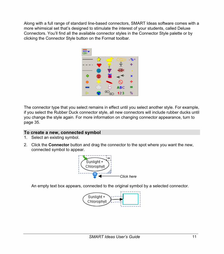
Along with a full range of standard line-based connectors, SMART Ideas software comes with amore whimsical set that’s designed to stimulate the interest of your students, called DeluxeConnectors. You’ll find all the available connector styles in the Connector Style palette or byclicking the Connector Style button on the Format toolbar.
The connector type that you select remains in effect until you select another style. For example,if you select the Rubber Duck connector style, all new connectors will include rubber ducks untilyou change the style again. For more information on changing connector appearance, turn topage 35.
To create a new, connected symbol1. Select an existing symbol.
2. Click the Connector button and drag the connector to the spot where you want the new,connected symbol to appear.
Click here
An empty text box appears, connected to the original symbol by a selected connector.

12 SMART Ideas User’s Guide
3. Enter text and then press the ENTER key on your keyboard.
A new symbol appears. This symbol is connected to the original symbol with aconnector.
To connect two symbols1. Select either symbol.
Click here and drag
2. Click the Connector button and drag the connector to the second symbol.
A connector now links both symbols.
Labeling ConnectorsConnectors graphically depict the link between two ideas. However, you may also want to labelconnectors with text to further clarify and explain the relationship between two symbols.
For example, students often have difficulty understanding the complex interrelationships amongthe characters in Hamlet. Creating a diagram, such as the one that follows, with labeledconnectors would help a class grasp these sometimes confusing relationships more easily.

SMART Ideas User’s Guide 13
To label a connector1. Select the connector.
2. Click once on the selected connector.
A text box appears.
3. Type the label.
4. Press the ENTER key on your keyboard.
The label appears in the center of the connector.

14 SMART Ideas User’s Guide
Editing a DiagramThis section will focus on how to:
• select objects for editing (page 14)
• move objects (page 15)
• rearrange diagrams (page 17)
• align objects (page 19)
• resize objects (page 20)
• delete objects (page 22)
• cut, copy and paste objects (page 23)
• protect objects from editing (page 23)
• undo changes (page 24)
Selecting Symbols and ConnectorsTo work with a symbol or connector, you must first select it. If you like, you can change severalsymbols or connectors simultaneously by selecting them at the same time. To select all objectsin the current workspace, click Select All on the Edit menu.
To select a symbol or connector1. Move the cursor over the object you want to select.
2. Click once.
If the object is a symbol, a selection rectangle with four icons encloses it. Click theseicons to perform a variety of operations, from resizing the symbol to creating connectorsto opening sub-levels.
Open Sub-level CollapseDiagram
ResizeCreate a Connector
Icon Functions in a Selection Rectangle
SMART Ideas User’s Guide 15
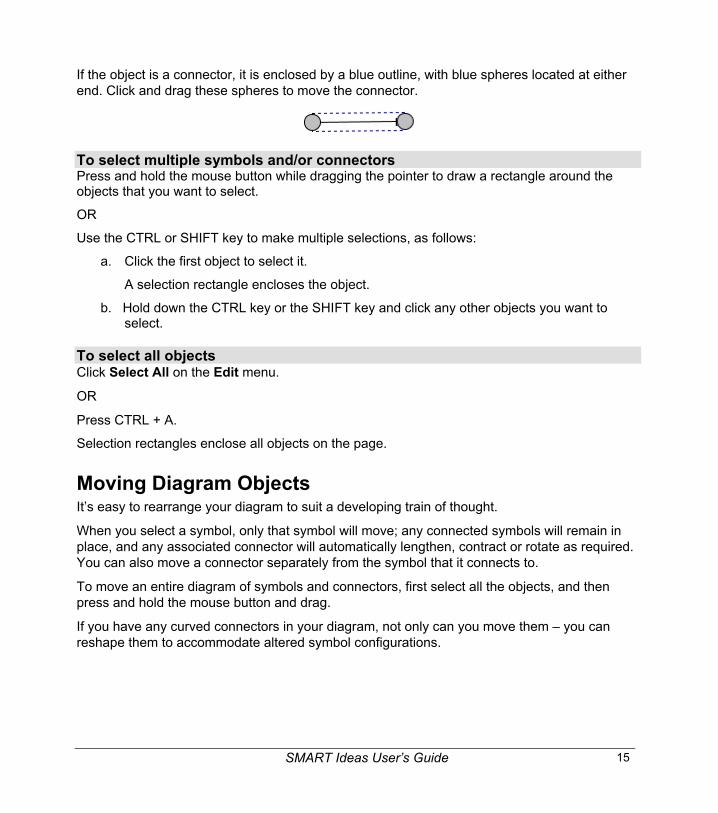
If the object is a connector, it is enclosed by a blue outline, with blue spheres located at eitherend. Click and drag these spheres to move the connector.
To select multiple symbols and/or connectorsPress and hold the mouse button while dragging the pointer to draw a rectangle around theobjects that you want to select.
OR
Use the CTRL or SHIFT key to make multiple selections, as follows:
a. Click the first object to select it.
A selection rectangle encloses the object.
b. Hold down the CTRL key or the SHIFT key and click any other objects you want toselect.
To select all objectsClick Select All on the Edit menu.
OR
Press CTRL + A.
Selection rectangles enclose all objects on the page.
Moving Diagram ObjectsIt’s easy to rearrange your diagram to suit a developing train of thought.
When you select a symbol, only that symbol will move; any connected symbols will remain inplace, and any associated connector will automatically lengthen, contract or rotate as required.You can also move a connector separately from the symbol that it connects to.
To move an entire diagram of symbols and connectors, first select all the objects, and thenpress and hold the mouse button and drag.
If you have any curved connectors in your diagram, not only can you move them – you canreshape them to accommodate altered symbol configurations.
16 SMART Ideas User’s Guide
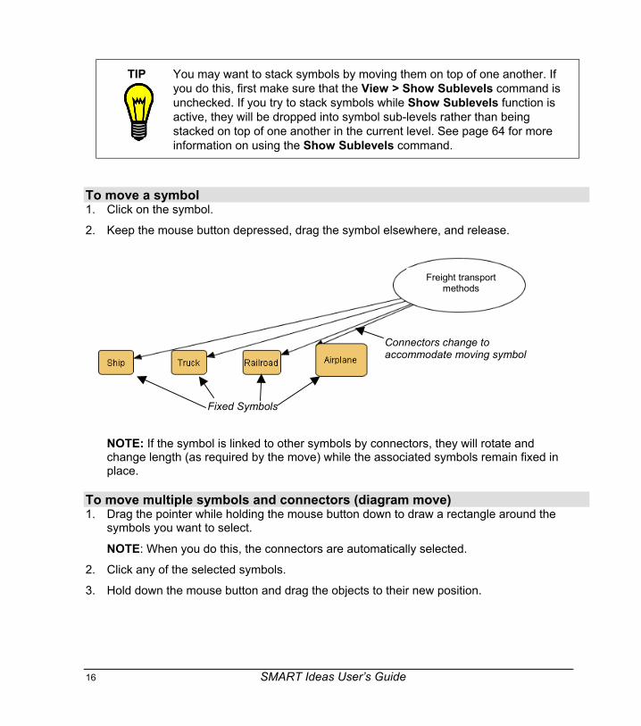
TIP You may want to stack symbols by moving them on top of one another. Ifyou do this, first make sure that the View > Show Sublevels command isunchecked. If you try to stack symbols while Show Sublevels function isactive, they will be dropped into symbol sub-levels rather than beingstacked on top of one another in the current level. See page 64 for moreinformation on using the Show Sublevels command.
To move a symbol1. Click on the symbol.
2. Keep the mouse button depressed, drag the symbol elsewhere, and release.
NOTE: If the symbol is linked to other symbols by connectors, they will rotate andchange length (as required by the move) while the associated symbols remain fixed inplace.
To move multiple symbols and connectors (diagram move)1. Drag the pointer while holding the mouse button down to draw a rectangle around the
symbols you want to select.
NOTE: When you do this, the connectors are automatically selected.
2. Click any of the selected symbols.
3. Hold down the mouse button and drag the objects to their new position.
Connectors change toaccommodate moving symbol
Fixed Symbols
Freight transportmethods

SMART Ideas User’s Guide 17
To connect to another symbol1. Select the connector.
A blue outline with blue spheres at both ends encloses the connector.
2. Click, hold and drag either sphere to another symbol.
3. Release the mouse button.
To reshape a curved connector1. Select the curved connector.
2. Click, hold and drag the blue square to change the angle of the connector curve.
Click, hold and drag
3. Release the mouse button when the curve is the desired shape.
Changing Diagram LayoutThe Layout feature of SMART Ideas software allows you to instantly arrange individualdiagrams (or all the diagrams on the page) in any of the following six layout patterns.
Click, holdand drag

18 SMART Ideas User’s Guide
When paired with the Quick Connect feature (page 7), the Layout feature lets you specify thearrangement of a diagram before you create it. However, you can also use it to change thelayout of a diagram (or a full page of diagrams) after you’ve created it.
If you like, you can also use the Layout feature to change the connector shapes from straight toright-angled.
NOTE: If you apply a layout to an entire page, all your diagrams are moved from their currentposition to a centrally aligned position on the page.
To change the layout of an existing diagram(s)1. Select one or more diagrams.
2. Click the Layout arrow.
3. If you want to use right-angle connectors in your diagram, select the Use Right-AngleConnector check box.
4. Click one of the six layout buttons to select a layout.
SMART Ideas software modifies the layout of all selected diagrams.
Right Tree Left Tree Bottom Tree
Top TreeRadial Ring

SMART Ideas User’s Guide 19
To change the layout of all diagrams on the current page1. Click the Layout arrow.
2. If you want to use right-angle connectors in your diagram, select the Use Right-AngleConnector check box.
3. Make sure the Apply to Entire Page check box is filled.
4. Click one of the six layout button to select a layout.
All diagrams on the current page will be rearranged and lined up on the page along acentral axis.
Aligning ObjectsUse the Align command to horizontally or vertically align any number of selected objects. Therelative placement of the majority of the objects determines the axis and location of theresulting alignment.
To align symbols automatically1. Select the symbols that you want to align.
2. Select Align from the Format menu.
The symbols align along the predominant axis of the original grouping (in this case, thehorizontal axis).

20 SMART Ideas User’s Guide
Resizing SymbolsIn addition to creating symbols of different colors and shapes, you also create symbols ofdifferent sizes to graphically demonstrate idea hierarchy. For example, you can tell at a glancethat a symbol represents the central idea if it is larger than the other symbols in the diagram.
To resize a symbol1. Select one or more symbols.
2. Click, hold and drag the Resize icon (in the lower-right corner of the selected symbol) toenlarge or contract the symbol.
Click, hold and drag
NOTE: To resize multiple, selected symbols at the same time, drag on the Resize iconthat will appear in a single symbol of the group.
3. Release the mouse button.

SMART Ideas User’s Guide 21
Resizing Symbols to Show All TextYou can type a lot of text into a symbol. However, when the symbol is small and can’taccommodate all the text you’ve entered, ellipsis points (…) indicate the text that isn’t shown.To enlarge the symbol so all text is displayed, just click the Resize icon in the lower-right cornerof the selected symbol. Alternatively, you can resize the symbol manually (see the previoussection).
Click here…
…for this result
If a symbol is much larger than the text requires, you can also click the Resize icon to shrinkthe symbol to neatly fit around the text.
Click here… …for this result

22 SMART Ideas User’s Guide
TIPS For lengthier text entries, attach a note to the symbol instead. When youmove your mouse pointer over the Note icon, the note appears in aneditable text box. See page 38 for more information.
Note Icon
If you want to display left-justified text inside a symbol that shows allyour text without resizing, consider using one of the four Text symbolstyles available at the end of the Symbol Style palette. (HINT: Use theforward arrow button at the top of the Symbol Style palette to pageforward to the end of the palette.)
With a Text symbol, all the text you enter will be displayed without anyneed for resizing. Unlike other symbol styles, this style allows you toinitiate new paragraphs by pressing the ENTER key on your keyboard.Also, when you’re finished, all your text – no matter how lengthy – will bedisplayed. You can move, edit, reformat or link this symbol style just asyou would any other symbol.
Four Text symbolstyles located atend of SymbolStyle palette
Deleting ObjectsWhen you delete a symbol, be aware that this action may have an impact beyond the simpledisappearance of the object. For instance:
• If a symbol has a hyperlink associated with it – for example, if it links to a file or Web site –that link is lost when you delete the symbol.

SMART Ideas User’s Guide 23
• If a symbol has one or more sub-levels, those sub-levels (and all the objects on them) arealso deleted.
Deleting a connector, however, affects only that connector. The symbols on either side willremain intact.
To delete an object1. Select one or more objects.
2. Click the Delete button on the toolbar.
The selected object(s) disappears.
Cutting, Copying and Pasting ObjectsUse the Cut, Copy and Paste functions to duplicate or move any object in your currentworkspace to another diagram, sub-level or application through the Microsoft WindowsClipboard.
To cut/copy and paste an object1. Select one or more objects.
2. Click the Cut or Copy button on the toolbar.
OR
Select Cut or Copy from the Edit menu.
NOTE: If you’re copying a symbol with an associated sub-level, you’ll be asked if youwant to copy the sub-level in addition to the symbol itself. Click the Yes button to copythe sub-level.
3. Click the Paste button in the toolbar.
OR
Select Paste from the Edit menu.
The object appears at the cursor insertion point.
Protecting Objects from EditingYou can protect an object or an entire group of objects from subsequent editing with the MakeBackground command. This command moves selected objects into the virtual background,out of reach of the selection tool.
NOTE: To restore all protected objects to the foreground for further revision, select RetrieveBackground from the Tools menu.
24 SMART Ideas User’s Guide
To protect an object from editing1. Select the objects that you want to send to the background.
2. Select Make Background from the Tools menu.
The object or objects that you selected are now part of the background (and are nolonger selectable).
Undoing ChangesIf you make a mistake (or simply change your mind), click the Undo button to reverse theprevious command or action that you committed.
You can undo many previous actions by selecting Undo repeatedly. Once you've undone apreviously issued command or object, you can also change your mind again and reinstate theoriginal object (or edit) by selecting Redo from the Edit menu.
To undo the effect of the last command or actionClick the Undo button in the toolbar.
OR
Select Undo from the Edit menu.
To redo the previous command revoked with UndoSelect Redo from the Edit menu.

SMART Ideas User’s Guide 25
Using StylesThis section tells you about:
• Using styles to format efficiently (page 25)
• Formatting symbols with styles (page 25)
• Formatting connectors with styles (page 27)
• Modifying existing styles and creating new styles (page 30)
• Loading styles from other IPR files into the current file (page 32)
Styles: An OverviewSuppose you’ve spent a few minutes changing the appearance of a symbol (or a connector) tolook exactly the way you want. You’ve changed the fill color of the symbol to just the rightshade of turquoise, added a unique color outline, chosen a distinctive shape, and made it 50%transparent.
Now you want several other symbols to look exactly the same. You could select those symbolsand apply the same formatting to each one, but that takes time, and it can be difficult toduplicate subtle shades of color with precision. Also, if you decide to change a small aspect ofthe symbols, you must repeat the work for each of them.
Instead, you can save the original formatting as a style, which is just a collection ofcharacteristics that you can then apply to any symbol. If you change the appearance of a styledirectly in the Style palette, those changes are automatically transferred to the symbols (orconnectors) that are based on that style.
SMART Ideas software comes with a number of ready-to-use symbol and connector styles.You can find them in the Style palette on the left side of the interface. While you may find thesestyles are sufficient, you can also use them as starting points for creating your own uniquestyles (see Creating New Styles on page 30).
Formatting Symbols with StylesUse the Style palette to predetermine the shape and color of a symbol before you create it.After you select a style, every symbol that you subsequently create has the characteristics ofthat style, until you select another style. If necessary, you can always change the appearanceof a symbol by using the formatting buttons in the toolbar (or the commands in the Formatmenu). However, if you want to use that symbol’s formatting when you create other symbols,you should create a new in the Style palette (see page 30).

26 SMART Ideas User’s Guide
While you can select any style to predetermine what your symbols will look like, you can alsoselect a symbol and then select a different style to change the selected symbol in a flash.
To create a new symbol with a predetermined style1. Click the Symbols button above the Style palette.
2. Click the style that you want to use in the Style palette.
Selected Style
3. Click in the workspace, type a message, and press ENTER.
OR

SMART Ideas User’s Guide 27
If you prefer to create a symbol without text, drag the selected style onto the workspace.
Drag and dropthe style intothe workspace
OR
Click again.
OR
Click the Insert button at the bottom of the Style palette.
A symbol appears in the selected style. If you click the Insert button repeatedly, thesymbols appear in a ring pattern. This is the fastest way to create multiple blanksymbols.
To apply a style to change an existing symbol1. Select a symbol in the workspace.
2. Click the Symbols button above the Style palette.
3. Select a style.
The selected symbol changes to match the selected style.
Formatting Connectors with StylesYou can predetermine the style of the connectors you’ll create in a diagram using the Stylepalette, just as you can for symbols. When you select a connector style, it remains in effect untilyou select another one.
Alternatively, you can use the connector toolbar buttons that are just above the workspace toformat a connector. However, if you change the connector appearance with the toolbar buttons,you will only change that single connector. The next connector you create will revert to the

28 SMART Ideas User’s Guide
current connector style. To apply the format of a connector to other connectors, you shouldtransform the connector into a style by loading it into the Style palette (see page 30).
To create a new connector based on a style1. Click the Connectors button above the Style palette.
2. Select a connector style.
SelectedConnector Style
3. Select any symbol, and then drag that symbol’s Connector icon to the spot where youwant the connected symbol to appear.
Click and drag… …for this result
The resulting connector is identical to the previously selected style.
SMART Ideas User’s Guide 29
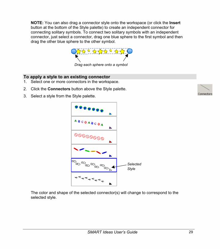
NOTE: You can also drag a connector style onto the workspace (or click the Insertbutton at the bottom of the Style palette) to create an independent connector forconnecting solitary symbols. To connect two solitary symbols with an independentconnector, just select a connector, drag one blue sphere to the first symbol and thendrag the other blue sphere to the other symbol.
Drag each sphere onto a symbol
To apply a style to an existing connector1. Select one or more connectors in the workspace.
2. Click the Connectors button above the Style palette.
3. Select a style from the Style palette.
SelectedStyle
The color and shape of the selected connector(s) will change to correspond to theselected style.

30 SMART Ideas User’s Guide
Modifying Existing Styles and Creating New StylesWhile many ready-to-use symbol and connector styles are provided with SMART Ideassoftware, it’s easy to create your own unique styles. You can alter an existing style in the Stylepalette or create a brand new style in the workspace and then import it into the Style palette.
If you modify an existing style in the Style palette, the formatting of all the symbols associatedwith that style immediately changes.
Any changed or new styles you add to the Style palette are saved with the document. Thismeans that you only need to create a new style once because you can load the stylesassociated with this document into any other SMART Ideas file, and use them again and againin other diagrams. See page 31 for more information.
Rather than just changing the Style palette for a single file, you can make the altered Stylepalette the new default so it appears whenever you create a new SMART Ideas file. See page31 for more information on changing the default Style palette.
To customize an existing style in the Style palette1. Select a style from the Symbols or Connectors sections of the Style palette.
2. Click the Customize button.
3. Select Font, Fill Color, Line Color, Shape or Transparency as required to alter thecharacteristics of the selected style. For more information, see Changing SymbolAppearance on page 34.
Any symbols that you created using the original style will immediately change to reflectthe new characteristics of the changed style.
To create a new style and import it into the Style palette1. Select a symbol.
SMART Ideas User’s Guide 31
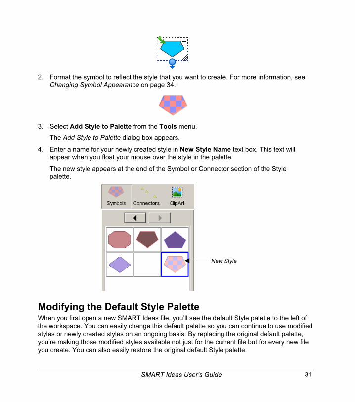
2. Format the symbol to reflect the style that you want to create. For more information, seeChanging Symbol Appearance on page 34.
3. Select Add Style to Palette from the Tools menu.
The Add Style to Palette dialog box appears.
4. Enter a name for your newly created style in New Style Name text box. This text willappear when you float your mouse over the style in the palette.
The new style appears at the end of the Symbol or Connector section of the Stylepalette.
New Style
Modifying the Default Style PaletteWhen you first open a new SMART Ideas file, you’ll see the default Style palette to the left ofthe workspace. You can easily change this default palette so you can continue to use modifiedstyles or newly created styles on an ongoing basis. By replacing the original default palette,you’re making those modified styles available not just for the current file but for every new fileyou create. You can also easily restore the original default Style palette.

32 SMART Ideas User’s Guide
If you prefer, you can simply load styles from other SMART Ideas (.ipr) files, making themavailable in the current file only (see page 32).
To change the default Style palette1. Modify the styles in the Style palette (page 30) or create new styles in the workspace
and import them into the Style palette (page 30).
2. Select Apply Styles to Default from the Tools menu.
3. Save the file.
4. Select New from the File menu.
A new file opens with the modified Style palette as the default.
To restore the original default Style paletteSelect Restore Default Styles from the Tools menu.
Loading Styles from Other IPR Files into the Current FileAfter you change the Style palette for one file, you can reuse the styles in that customizedpalette in any other SMART Ideas file.
Using the Import Styles command, just select a SMART Ideas file to import. When you do this,only the styles are imported – not the diagrams that are associated with that file. SMART Ideassoftware adds the imported styles at the end of the current Style palette. Those symbols in theimported palette that have an exact match in the current Style palette are not imported.
NOTE: If you want to use a customized Style palette in all new files, you may prefer to replacethe original default Style palette with the customized palette (page 31).
To load customized styles into the current style palette1. Select Import Styles from the Tools menu.
The Open dialog box appears.
2. Browse to the SMART Ideas (.ipr) file that contains the styles you want to import.
OR
Enter the name of the .ipr file in the File name field.
3. Click the Open button.
The new (unique) styles (both symbol and connector) appear in the Style palette.
SMART Ideas User’s Guide 33
Deleting StylesTwo arrow buttons at the top of the Style palette allow you to navigate to other pages of styles.However, if you’ve added a lot of new styles, or you find that you only use a few of the manyready-made styles in the style palette, you may want to delete a few styles so as to avoid usingthese buttons.
To delete a style1. Select a style from the Symbols or Connectors section of the Style palette.
2. Click the Customize button at the bottom of the Style palette.
3. Select Delete from the menu.
The style will disappear from the Style palette.
34 SMART Ideas User’s Guide
Customizing Your DiagramIn this section, you’ll learn how to make your diagrams more distinctive by:
• customizing the color, line weight, transparency, shape, etc. of a symbol (page 34)
• changing the appearance of connectors by selecting different line weights, colors, shapesand arrowheads (page 35)
• adding a note to a symbol (page 38)
• importing an image to use as a symbol (page 42)
• using clip art as a symbol (page 44)
• importing your own collections of clip art (page 47)
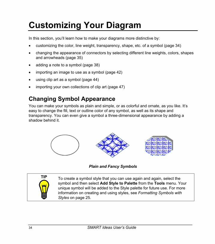
Changing Symbol AppearanceYou can make your symbols as plain and simple, or as colorful and ornate, as you like. It’seasy to change the fill, text or outline color of any symbol, as well as its shape andtransparency. You can even give a symbol a three-dimensional appearance by adding ashadow behind it.
Plain and Fancy Symbols
TIP To create a symbol style that you can use again and again, select thesymbol and then select Add Style to Palette from the Tools menu. Yourunique symbol will be added to the Style palette for future use. For moreinformation on creating and using styles, see Formatting Symbols withStyles on page 25.

SMART Ideas User’s Guide 35
To customize the fill, shape and outline of a symbol using the Formatting toolbar1. Select one or more symbols.
2. To change the fill color, click the Fill Color arrow on the Formatting toolbar, select acolor from the palette, or click the More Colors button to access a larger color selection.
To change the outline color, click the Outline Color arrow on the Formatting toolbar,select a color from the palette, or click the More Colors button.
To change the shape, select Shape from the Format menu (or right-click and selectShape), and then select a shape from the list.
NOTE: To change a symbol’s text attributes, see Formatting Text on page 69.
Changing Connector AppearanceYou can modify a connector as easily, and in almost as many ways, as a symbol. In previoussections, we discussed labeling connectors (page 12), linking symbols with connectors (page10), and using styles to format connectors (page 27). Here, we’ll focus on changing theappearance of a connector using the formatting toolbar.
SMART Ideas software offers a wide range of connector shapes, types, colors, weights andends from which to choose. A connector can be straightforward, angled or even amusing (seethe Deluxe Connectors on page 10). For example, the following diagram uses three differentconnector styles.

36 SMART Ideas User’s Guide
TIP To create a connector style that can be used again and again, select theconnector, and then select Add Style to Palette from the Tools menu.Your unique connector will be imported into the Style palette for future use.For more information on creating and using styles, see Formatting Symbolswith Styles on page 25.
To customize a connector using the Formatting toolbar1. Select one or more connectors.
2. To change the connector shape to angled, curved or straight, click the Connector Typebutton.
To change the connector line thickness, click the Line Thickness button.
To change the connector line color, click the Line Color button.
To change the connector ends to single, double, filled, transparent or no arrowheads,click the Arrow Style button.
To use an image-based connector, click the Deluxe Connector button.
To change the color of an image-based connector, click the Fill Color button.
NOTE: To customize connector labels, see Formatting Text on page 69.
Adding Two-Color Patterns and Gradients to Symbol FillsYour symbols can have a uniform, single-color fill, a two-color patterned fill or a two-colorgradient fill. The patterned fills are regularly recurring symmetrical objects that create a tiledappearance, similar to wallpaper. The gradient fills display a progression between two colorsalong either a vertical, diagonal or horizontal path.
A Two-Color Pattern A Vertical Gradient Fill

SMART Ideas User’s Guide 37
To add a two-color pattern or gradient to the symbol fill1. Select a symbol(s).
2. Click the Fill Color arrow on the Formatting toolbar and click the Fill Effects button.
Click here
The Fill Effects dialog box appears.
Click apattern type
Preview ofPattern andColors
Click to selectthe two colorsfor the pattern
38 SMART Ideas User’s Guide
3. To add a pattern to the symbol fill, click one of the pattern types.
OR
To add a gradient fill, click the Gradients tab and click a gradient type.
4. Click the two color buttons at the bottom of the window to select the two colors that willmake up the pattern or the gradient.
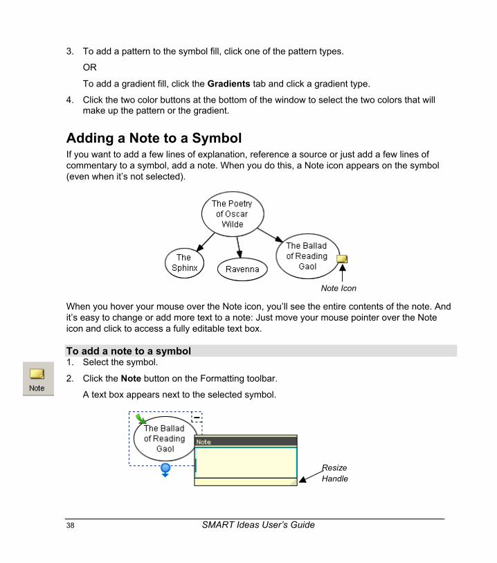
Adding a Note to a SymbolIf you want to add a few lines of explanation, reference a source or just add a few lines ofcommentary to a symbol, add a note. When you do this, a Note icon appears on the symbol(even when it’s not selected).
Note Icon
When you hover your mouse over the Note icon, you’ll see the entire contents of the note. Andit’s easy to change or add more text to a note: Just move your mouse pointer over the Noteicon and click to access a fully editable text box.
To add a note to a symbol1. Select the symbol.
2. Click the Note button on the Formatting toolbar.
A text box appears next to the selected symbol.
ResizeHandle

SMART Ideas User’s Guide 39
3. Type a note.
TIPIf you’re writing a long note, you may need to resize the text box for optimalvisibility. Just drag the Resize handle in the bottom right corner of the textbox after you’ve entered the note text.
4. Click once outside of the text box.
A Note icon appears on the symbol.
Note Icon
5. Move your mouse pointer over the Note icon to view the note text.
To edit a note1. Click the Note icon.
The note contents appear inside a text box.
2. Add or change the text as you prefer.
3. Click once outside of the text box to commit the text.

40 SMART Ideas User’s Guide
Making a Symbol TransparentIn SMART Ideas software, you can make a filled symbol 25%, 50%, 75% or 90% transparent –a range of transparency that lets you make a symbol only a little more transparent than otherdiagram objects, or so faint it’s nearly invisible.
TIPS • Use the degree of transparency to reflect the relative importance of theideas or facts your symbols may represent. Or use it to show temporalrelationships, giving older events in a timeline a more fadedappearance than recent events.
• You can make overlapping objects transparent so they don’t obscurethe underlying objects in your diagram.
To make a symbol transparent1. Select a filled symbol.
2. Select Format > Transparency and select a degree of transparency.
OR
Right-mouse click and select Transparency and a degree of transparency.
The transparency for selected symbol changes accordingly.

SMART Ideas User’s Guide 41
Adding a Shadow to a SymbolGive your diagram the appearance of depth by adding shadows to your symbols. You can usethe default gray color or select any other color. Note that you must also specify the corner ofthe symbol in which you want the shadow placed.
To add a shadow to a symbol1. Select a symbol.
2. Select Shadow from the Format menu.
3. Click a Shadow Direction button to select the corner that the shadow will occupy.
Upper-LeftCorner
Upper-RightCorner
Lower-RightCorner
Lower-LeftCorner
The selected symbol appears with a gray shadow in the specified corner (in the examplebelow, the upper-right corner).
To add a colored shadow to a symbol1. Select a symbol.
2. Select Shadow from the Format menu.
3. Click the Shadow Color button and select a color.
The selected symbol appears with a colored shadow in the last corner specified.
NOTE: The next time you create a shadow, the default shadow color (gray) is restored.

42 SMART Ideas User’s Guide
Using an Imported Image as a SymbolYou can add visual appeal to any diagram you’re developing by importing a .bmp, .jpg, .jpeg,.gif, .png, .svg, .ico or .wmf image file and using it as a symbol. You can then connect thatsymbol to other symbols in a diagram and customize it just as you would any other symbol.
For example, in the diagram on Hamlet shown on page 13, you could use public-domainphotographs – like the photograph in the symbol below of Richard Burton playing Hamlet – torepresent each character. Such an image makes a much more memorable symbol than simplyenclosing the word “Hamlet” in a shape (although you can integrate that word into the symbolas well).
TIPIf you intend to use an image symbol on a regular basis, consider importingthe image into the clip art gallery as described on page 47.
SMART Ideas User’s Guide 43
To use an imported image as a symbol1. Select one or more symbols.
2. Select Image from File from the Insert menu.
An Open dialog box appears.
3. Browse to the image file you want to import into the diagram.
NOTE: You can import BMP, JPG, JPEG, GIF, PNG, SVG, ICO and WMF files.
4. Click the Open button.
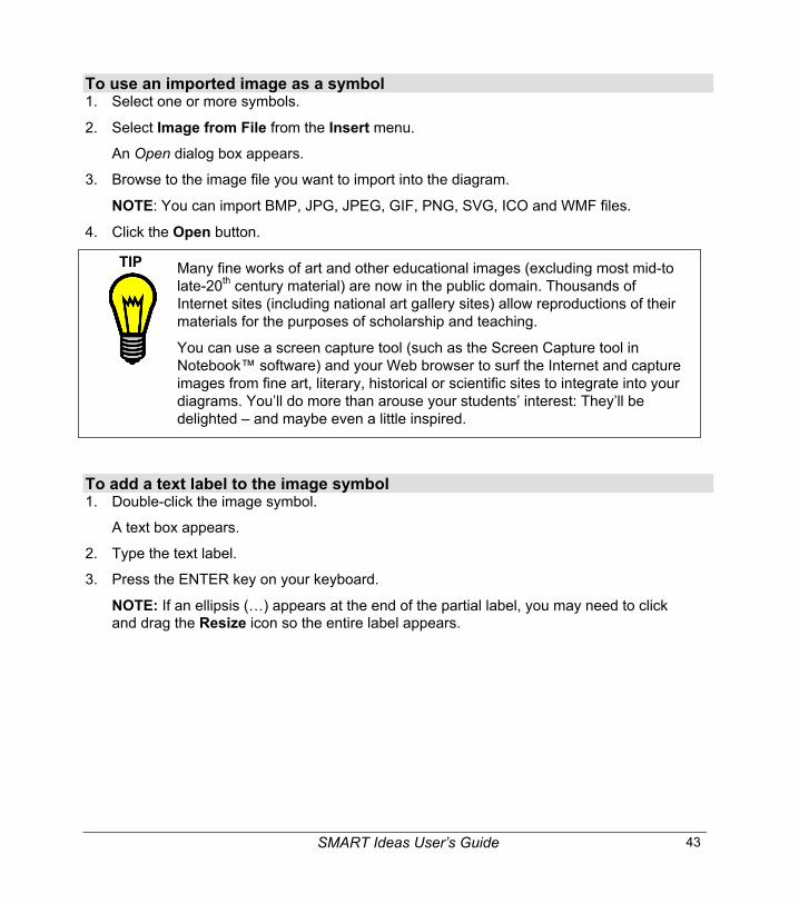
TIP Many fine works of art and other educational images (excluding most mid-tolate-20th century material) are now in the public domain. Thousands ofInternet sites (including national art gallery sites) allow reproductions of theirmaterials for the purposes of scholarship and teaching.
You can use a screen capture tool (such as the Screen Capture tool inNotebook™ software) and your Web browser to surf the Internet and captureimages from fine art, literary, historical or scientific sites to integrate into yourdiagrams. You’ll do more than arouse your students’ interest: They’ll bedelighted – and maybe even a little inspired.
To add a text label to the image symbol1. Double-click the image symbol.
A text box appears.
2. Type the text label.
3. Press the ENTER key on your keyboard.
NOTE: If an ellipsis (…) appears at the end of the partial label, you may need to clickand drag the Resize icon so the entire label appears.
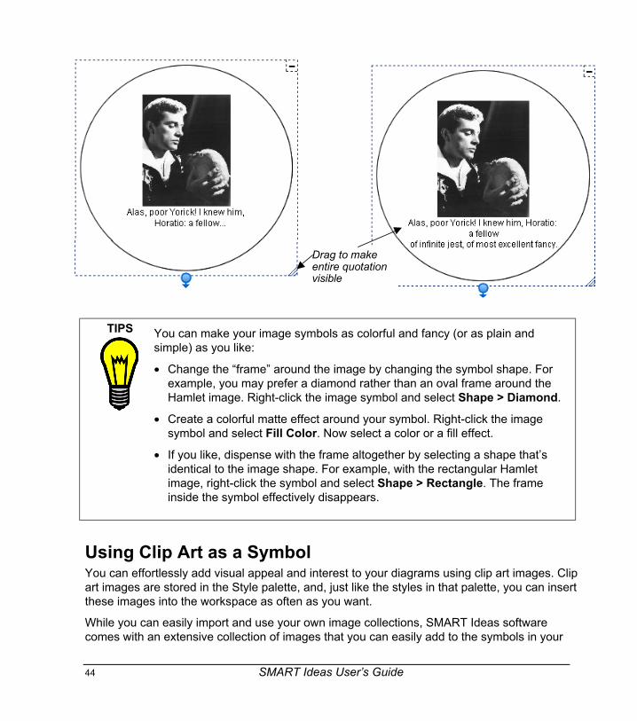
44 SMART Ideas User’s Guide
Drag to makeentire quotationvisible
TIPS You can make your image symbols as colorful and fancy (or as plain andsimple) as you like:
• Change the “frame” around the image by changing the symbol shape. Forexample, you may prefer a diamond rather than an oval frame around theHamlet image. Right-click the image symbol and select Shape > Diamond.
• Create a colorful matte effect around your symbol. Right-click the imagesymbol and select Fill Color. Now select a color or a fill effect.
• If you like, dispense with the frame altogether by selecting a shape that’sidentical to the image shape. For example, with the rectangular Hamletimage, right-click the symbol and select Shape > Rectangle. The frameinside the symbol effectively disappears.
Using Clip Art as a SymbolYou can effortlessly add visual appeal and interest to your diagrams using clip art images. Clipart images are stored in the Style palette, and, just like the styles in that palette, you can insertthese images into the workspace as often as you want.
While you can easily import and use your own image collections, SMART Ideas softwarecomes with an extensive collection of images that you can easily add to the symbols in your

SMART Ideas User’s Guide 45
diagrams. For example, the following diagram showing the life cycle of the frog was createdentirely from clip art that’s available in the gallery.
When you add a clip art image to a diagram, it becomes a symbol you can treat like any othersymbol. You can surround the image with symbol shapes, resize it, connect it to other symbols,and add text to it.
To use an image from the clip art gallery as a symbol1. Click the Clip Art button at the top of the Style palette.

46 SMART Ideas User’s Guide
Navigate through theselected category
Click an image to selectthe associated clip art.Double-click to insert theclip art into theworkspace.
Add your own clipart category
Insert the selected clip artinto the workspace
Select a category
2. Click the arrow above the images to select a category from the list.
NOTE: Click All Categories to see all the available images.
3. Drag the image you want into the workspace.
OR

SMART Ideas User’s Guide 47
Click the image you want and then click the Insert button at the bottom of the Stylepalette.
OR
Click again on the image in the Style palette.
4. To frame the clip art image with a shape, select a symbol from the Style palette.
Importing Images into the Clip Art GalleryYou can integrate your favorite images into your diagrams by importing your own imagecollections into the clip art gallery. With SMART Ideas software, you can import any .jpg, .gif,.png, .bmp, .ico, .wmp or .svg file into the gallery. Keep your images organized and easy to findby importing them directly into an existing category or create an entirely new category.
You can also import a clip art collection that’s associated with another SMART Ideas file usingthe Import Styles command on the Tools menu (see page 32).
To add images to the clip art gallery1. Click the Clip Art button at the top of the Style palette.
2. Click the Customize button (at the bottom of the Style palette) and then select Add ClipArt.The Open dialog box appears.
3. Browse to the image file(s) that you want to add to the clip art gallery.
NOTE: You can select multiple files to add using the CRTL key or the SHIFT key onyour keyboard.
OR
Enter the path and file name of a single image file in the File name field.
4. Click the Open button.
The Select Category dialog box appears.
48 SMART Ideas User’s Guide
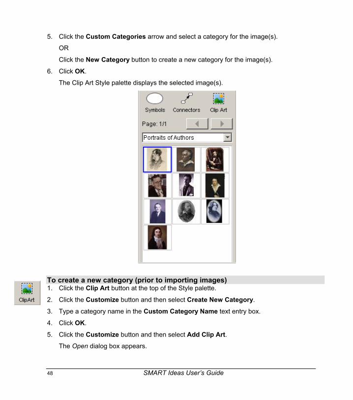
5. Click the Custom Categories arrow and select a category for the image(s).
OR
Click the New Category button to create a new category for the image(s).
6. Click OK.
The Clip Art Style palette displays the selected image(s).
To create a new category (prior to importing images)1. Click the Clip Art button at the top of the Style palette.
2. Click the Customize button and then select Create New Category.
3. Type a category name in the Custom Category Name text entry box.
4. Click OK.
5. Click the Customize button and then select Add Clip Art.The Open dialog box appears.

SMART Ideas User’s Guide 49
6. Browse to the image files you want to import.
7. Click OK.
The Select Category dialog box appears.
8. Click the Custom Categories drop-down arrow and select the category name enteredpreviously (in step 3).
9. Click OK.
To delete an image from the clip art gallery1. Select an image from the clip art gallery.
2. Select Delete Clip Art from the Customize menu.
To delete a category from the clip art gallery1. Click the Customize button and then select Delete Category.
The Select Category dialog box appears.
2. Click the Custom Categories drop-down arrow and select the category you want to delete.
3. Click OK.
The category and all its associated images will be deleted from the clip art gallery.
Searching for Clip ArtThe clip art gallery provided with SMART Ideas software contains scores of images organizedinto such subject categories as social studies, language arts, math and science. To these, youcan import as many of your own images as you like, resulting in a potentially vast collection ofimages. A search engine provided in the Clip Art Gallery dialog box (not in the Style palette)makes it easy to find just the right image. Just enter a keyword to search either the entiregallery of images or single categories.
NOTE: Any image files you import will be searched by the first part of their filenames (the fileextension isn’t necessary). For example, if you import a file called Byron.jpg, enter the keyword“Byron” to find the associated image in the clip art gallery.
To search the clip art gallery by keyword1. Select Clip Art from the Insert menu.
The Clip Art Gallery dialog opens.
2. In the Category list, select a category to search.
OR

50 SMART Ideas User’s Guide
Select All Categories.
3. Enter a keyword in the Keyword box.
4. Click the Search button.
Any image with the keyword in its filename is displayed in the Search Results area.

SMART Ideas User’s Guide 51
Using Interactive ClipletsCliplets are an animated form of clip art that you can insert into the workspace and interact withto accomplish many teaching objectives. The cliplets provided with SMART Ideas software willhelp you teach geometry, clock reading, metric/imperial measurements and basic arithmeticprinciples.
The cliplets include timers, a pair of dice, teaching clocks, actual working clocks, and a fullyfunctioning calculator. The dice, for example, can be used just like regular dice. Instead ofrolling the dice, however, you just click on the image of the dice, and the number of dotschanges randomly. Similarly, you can drag the arms of the protractor cliplet to measure anangle or press the buttons in the calculator cliplet to solve a math problem.
Click anywhereon the image to“roll” the dice
Before Click After Click
Inserting ClipletsOnce you insert a cliplet, you can click, drag or otherwise manipulate components of the imageto fulfill the purpose of the cliplet. For example, you can drag the arms of the protractor cliplet tomeasure an angle or press the buttons in the calculator cliplet to solve a math problem.
Most cliplets are easier to use if you lock them into place first. Otherwise, you may move theentire cliplet rather than the functional part of the cliplet, such as the protractor arm. To lockcliplets in place, click the Tack button in the upper-left corner of the selected cliplet. Also, youcan access Help for those cliplets with complicated functionality by clicking the Help button inthe lower-right corner of the selection rectangle.
Some cliplets, such as the timers and clocks, also feature a Maximize button in the upper-rightcorner of the selection rectangle. The Maximize button enlarges the cliplet so that it takes upthe entire screen. You can then use a clock cliplet with a much larger face for teaching time-telling, or set the timer for in-class tests and then maximize it so it can be viewed more easilyby the entire class.

52 SMART Ideas User’s Guide
Click to lockthe cliplet inplace
Click for Help
Click tomaximize tofull-screensize
To insert a cliplet1. From the Insert menu, select Cliplet.
The Cliplet Gallery dialog box opens.
2. Click the Category scroll-down button and select a category of cliplets.
3. Select a cliplet from the displayed images.
4. Click the Insert button.
The cliplet is inserted in your diagram.
5. Drag the clip to the position that you want.
6. To tack the cliplet in place, click the Tack button in the upper-left corner of the selectionrectangle.
To search for a cliplet1. From the Insert menu, select Cliplet.
The Cliplet Gallery dialog box opens.
2. In the Category list, select All Categories.
SMART Ideas User’s Guide 53
3. In the Keywords field, enter a keyword.
4. Click Search.
Any file in the Cliplet folder with the keyword in its file name is displayed in the SearchResults area.
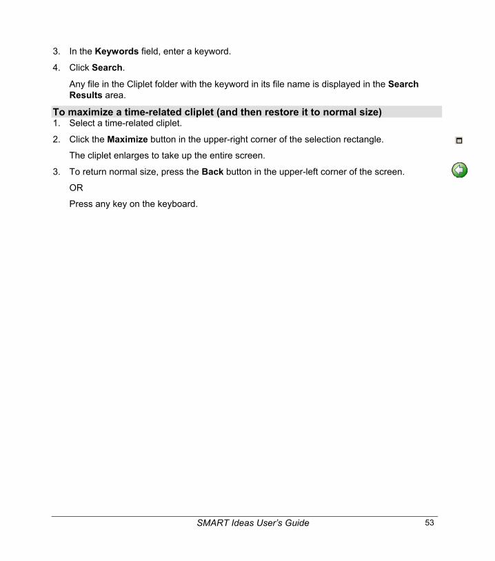
To maximize a time-related cliplet (and then restore it to normal size)1. Select a time-related cliplet.
2. Click the Maximize button in the upper-right corner of the selection rectangle.
The cliplet enlarges to take up the entire screen.
3. To return normal size, press the Back button in the upper-left corner of the screen.
OR
Press any key on the keyboard.

54 SMART Ideas User’s Guide
Getting to Know the Workspace
Workspace Sub-LevelsWith SMART Ideas software, diagrams can have the added dimension of depth. Every symbolin a diagram is a potential gateway to another symbol or a fully connected diagram that’slocated on a deeper level. Use a symbol’s sub-level to illustrate or expand on the idea thatsymbol represents. You can create as many sub-level layers as you want, because any symbolon a sub-level can have its own sub-level, and so on.
The following figure depicts three symbols and their accompanying sub-levels in cross section:symbols on the main level (symbols 1 and 2) have associated sub-levels, and one symbol on asub-level (symbol 3) has its own sub-level.
Main Level1
Symbol 1 Sub-Level
2
Symbol 2 Sub-Level
2
3
Symbol 3 Sub-Level
To access a symbol’s sub-level, select the symbol and then click the Sub-level (arrow) icon inthe upper-left corner.
Click here
You’ll immediately see a new workspace, in which you can create another diagram, asupporting set of exercises, a related image, etc. Click the Back button on the toolbar (or clickthe text link in the upper-left corner of the workspace) to return to the original level.
If your diagram has multiple sub-levels, you may want to use the Global view feature describedon page 55. In this view, you can see your main level and all associated sub-levels spread out
SMART Ideas User’s Guide 55
in the form of an interconnected map. The Global view also allows you to instantly access anylevel by clicking on its link.
For more information about creating and working with sub-levels, see page 72.
Workspace ViewsSMART Ideas software provides three distinct views of your work – Diagram, Outline andGlobal view. You can switch between these views using the tabs at the bottom of theworkspace.
Diagram and Outline ViewThe Diagram view is the view you’ll use most of the time. It’s the default view that gives you theworkspace and tools you need for making your diagrams.
However, to view a text-based, linear counterpart to your diagram, access the Outline view.This view is a ready-made outline that your students can use for organizing a writing project.They can brainstorm and develop connections between ideas in the Diagram view, and thentoggle to the Outline view when they’re ready to move from rough ideas to a finished document.
The Outline view isn’t just for viewing a text version of your diagram. You can also write(creating new symbols, connectors and even sub-levels), rearrange and revise ideas, and anychanges you make are immediately reflected in the Diagram view.
Global ViewIf you frequently use sub-levels to create a complex, interconnected web of diagrams, theGlobal view provides a very useful overview of all your work. This view is a two-dimensionaldepiction in miniature of every diagram at every level, so you can conveniently see everythingat once and instantly access any diagram with a mouse click. In addition, the link between thesub-level diagram and its associated upper-level symbol is clearly shown, so it provides auseful roadmap to your multi-dimensional workspace.
For example, if you created a diagram on the main level, in which each symbol represented astudent in a science research group, you might capture the outline of each student’s project ina sub-level diagram that’s associated with their name.

56 SMART Ideas User’s Guide
If you clicked the Sub-level (arrow) icon on the symbol for John, you’d find a sub-leveloccupied with a diagram outline of John’s research project:
SMART Ideas User’s Guide 57
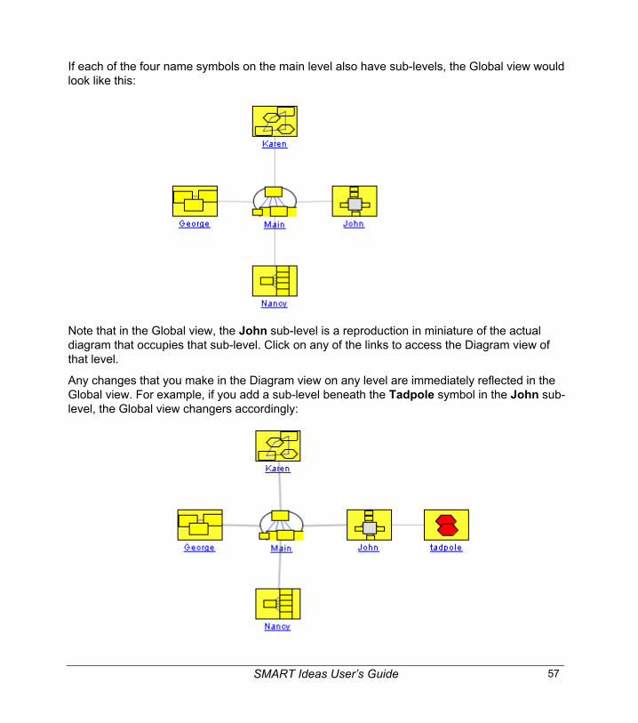
If each of the four name symbols on the main level also have sub-levels, the Global view wouldlook like this:
Note that in the Global view, the John sub-level is a reproduction in miniature of the actualdiagram that occupies that sub-level. Click on any of the links to access the Diagram view ofthat level.
Any changes that you make in the Diagram view on any level are immediately reflected in theGlobal view. For example, if you add a sub-level beneath the Tadpole symbol in the John sub-level, the Global view changers accordingly:

58 SMART Ideas User’s Guide
Maximizing the WorkspaceYou can enlarge the SMART Ideas workspace by selectively hiding:
• the Standard toolbar
• the Formatting toolbar
• the Style palette
You can enlarge the Style palette to take up the entire workspace, allowing you to focus oncustomizing styles to the exclusion of other activities, or you can drag the Style palette sidebarto selectively enlarge or contract the palette.
FormattingToolbar
StandardToolbar
StylePalette
Drag the sidebar to change the size of the Stylepalette
Click to hide the Style palette
Click to fully expand the Style palette
View Tabs

SMART Ideas User’s Guide 59
To hide either toolbar or the Style paletteSelect View > Toolbars and uncheck the toolbar or palette that you want to hide.
The Workspace will enlarge accordingly.
To shrink or expand the Style paletteClick the Expand arrow at the upper-right corner of the Style palette to enlarge it.
OR
Click the Contract arrow to hide it.
NOTE: Drag the inner sidebar to selectively expand or contract the palette.
To hide/show the Formatting toolbarClick the Hide Formatting button in the Formatting toolbar to make that toolbar disappearfrom view.
Click the Show Formatting button in the Standard toolbar to make the Formatting toolbarreappear.
Using the ToolbarsYou can activate many of the most frequently used functions on the two toolbars that aresituated just above the workspace.
The Standard ToolbarThe upper toolbar is the Standard toolbar, which contains conventional file management andediting tools, as well as diagram creation and viewing tools.
Return toprevious level
Save thecurrent file
Cut object
Copy object
Paste object
Delete object
Undo lastaction
Create ahyperlink
Add a note toa symbol
Select a layoutfor a quickconnect diagram
Activate the QuickConnect Feature
Move around theworkspace
Zoom in or out of theworkspace
ShowFormattingToolbar

60 SMART Ideas User’s Guide
The Formatting ToolbarThe Formatting toolbar is situated just above the workspace and contains tools for changingthe appearance of symbols and connectors. You can choose to hide or show this toolbar,depending on whether you need more display space or easy access to formatting tools.
Font Type
Bold
Text Formatting Buttons
FontSize
Symbol FormattingButtons
ConnectorFormatting Buttons
Line Color
Deluxe Connectors
ItalicsConnectorType
Line Thickness
Arrow Style
Font Color
Fill Colorand Effects
HideFormattingToolbar
Outline View ToolsThe formatting toolbar is grayed out (inactive) in the Outline view. However, in this view, thefollowing Outline tool buttons will appear at the end of the Standard toolbar:
Use the Outline view tools to:
• create a new main-level symbol
• promote a selected symbol (overriding the previous connection)
• demote a selected symbol (that’s connected to higher-level symbol)
Using the Workspace GridUse the grid to precisely align the objects in your diagrams. When you activate the grid, aseries of faint, intersecting vertical and horizontal lines, similar to graph paper, appears. Usethis unobtrusive grid to assist in aligning symbols.

SMART Ideas User’s Guide 61
You may have noticed that the three preceding symbols are perfectly aligned. When the grid ison, the built-in “snap-to” functionality makes it easy to arrange objects: SMART Ideas softwareautomatically nudges the center of every object you move to the center of a grid box.
When the grid is off, the “snap-to” functionality is deactivated, and you again have free-movingcontrol over object placement.
To activate the gridSelect Grid from the View menu.
Changing the Background ColorThe default background color for the Diagram view is plain white, with or without a grid. If youprefer, you can use almost any color to make the background of your SMART Ideas workspacecolorful and eye-catching.
NOTE: The background color also appears when you print the diagram on a color printer.
TIPChange the background color frequently so the workspace never becomesboring for your students.
To change the background color1. Select View > Background Color and then click on a color in the 40-color palette.
OR
To create a custom color, click More Colors.
The Choose Color dialog box appears.

62 SMART Ideas User’s Guide
Clickanywhereto changehue andsaturation Move the
slider toadjust thebrightnessPreview area
2. Click anywhere on the color swatch to change the hue and saturation, and then movethe slider in the color gradient to change the luminescence (brightness).
3. Click OK.
Using the Zoom FeatureUse the Zoom feature to magnify or reduce the size of the workspace, zooming in or out so youcan see a more detailed or general view of your diagrams. SMART Ideas software providescontinuous zoom options between 25% and 300% via a zoom slider on the toolbar. A non-continuous zoom feature is available in increments that range from 25% to 100% from the View> Zoom menu.
The Scale to Fit setting adjusts your view automatically so you can see all the objects in theworkspace (at optimal zoom) without scrolling.
The diagram prints at the same perspective as the current zoom level.
NOTE: As long as you save it, SMART Ideas software remembers the magnification youspecified for a file when you next open it, so you can maintain different magnification levels fordifferent files.
To change the magnification of a workspace1. Click the Zoom button on the toolbar.
A Zoom slider appears.

SMART Ideas User’s Guide 63
2. Drag the slider to the zoom level that you want.
OR
Click the Scale to Fit button to view all the objects in the workspace at an optimal zoomlevel.
Moving Around the WorkspaceIf you click the Pan button, you can drag the workspace in any direction, changing your vieweasily and accurately without resorting to the scroll bars.
With the Pan button depressed, you can still click on individual objects to select them, and, ifyou click the CTRL or SHIFT key, you can select multiple objects in this way too. Once objectsare selected, click and hold again on the object (or one of several) and drag the cursor to movethem.
To move the workspace with the Pan feature1. Click the Pan button on the toolbar.
2. Click, hold and drag in any direction on the workspace.
3. Click the Pan button to restore normal click-and-drag selection behavior.

64 SMART Ideas User’s Guide
Viewing Sub-LevelsIf you like, you can view small, ghost-like images of any diagrams that are associated with thesub-level of a symbol. In other words, you can see at a glance which symbols have sub-leveldiagrams, as well as the relative complexity of those diagrams.
The Show Sub-levels function also allows you to drag a selected symbol into any symbol’ssub-level. For more information on dragging symbols directly into sub-levels, turn to page74.
To activate the Show Sublevels commandCheck Show Sublevels on the View menu.
A small, faint image of the sub-level diagram appears inside each originating symbol.
Viewing (and Using) Sub-Level WatermarksIf you create a lot of sub-levels, you’ll want to use the sub-level watermarks to stay oriented.You’ll notice a watermark of faint blue text links in the top-left corner of each level. Thiswatermark appears by default and is derived from the originating symbol text for the currentlevel, as well as the originating symbol text from all other related sub-levels.
Click on the different links in the watermark to return to the original (Main) level or to the othersub-levels.
Click a link to go tothat sub-level
Current level
Click to go theoriginal level

SMART Ideas User’s Guide 65
To reduce workspace clutter, you can easily hide the watermarks.
To hide the sub-level watermarksUncheck Show Watermark on the View menu.
Contracting and Expanding Diagram TreesConcept maps are almost always hierarchical, beginning with broad, general concepts andthen branching out into specific details. This hierarchical organization gives your diagrams atree-like appearance. Think of the main idea or topic symbol as the trunk of a tree thatbranches into related subsidiary ideas, which can sprout many smaller branches of supportingdetails.
Note the tree-like structure of the following diagram. This diagram explores the characteristicsof literary tragedy, starting with the generic elements common to all tragedies and ending withspecific Shakespearean tragedies that illustrate those elements.
A Complex Diagram Tree

66 SMART Ideas User’s Guide
Such an elaborate diagram tends to be visually intimidating and difficult to grasp all at once. Forthe sake of clarity, you may want to hide the symbols that reside on the branch ends until you’reready to discuss them. This way, your students can focus on general concepts first, and then youcan selectively reveal supporting details – but only when you’re ready to discuss them.
SMART Ideas software includes a set of commands and icons that let you expand or collapseeither all trees on the current level or selected branches of a diagram tree, one hierarchicallevel at a time.
NOTE: If you save the file with collapsed or expanded trees, the file will re-open in the identicalstate.
To shrink a diagram tree by one level1. Click the symbol from which you want to collapse the tree.
2. Click the Collapse icon.
All the branches that emerged from the selected symbol disappear from view, so onlythe selected symbol is displayed.
You’ll notice the appearance of a new icon in the symbol’s selection rectangle. This isthe Expand icon. Click this icon to expand the tree by a single level.
Expand Icon
To shrink all trees on the current levelSelect Collapse All Trees from the View menu.
All diagrams on the current level collapse down to their single, originating symbols.
To expand a tree by one levelClick the Expand icon in the upper-right corner of the symbol at the top of the level you wantto expand.
To expand all tress on the current levelSelect Expand All Trees from the View menu.
All diagrams on the current level will expand fully, displaying all branches at once.
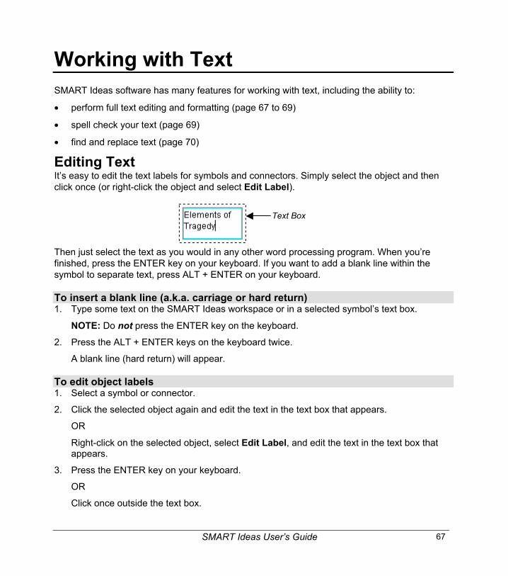
SMART Ideas User’s Guide 67
Working with TextSMART Ideas software has many features for working with text, including the ability to:
• perform full text editing and formatting (page 67 to 69)
• spell check your text (page 69)
• find and replace text (page 70)
Editing TextIt’s easy to edit the text labels for symbols and connectors. Simply select the object and thenclick once (or right-click the object and select Edit Label).
Text Box
Then just select the text as you would in any other word processing program. When you’refinished, press the ENTER key on your keyboard. If you want to add a blank line within thesymbol to separate text, press ALT + ENTER on your keyboard.
To insert a blank line (a.k.a. carriage or hard return)1. Type some text on the SMART Ideas workspace or in a selected symbol’s text box.
NOTE: Do not press the ENTER key on the keyboard.
2. Press the ALT + ENTER keys on the keyboard twice.
A blank line (hard return) will appear.
To edit object labels1. Select a symbol or connector.
2. Click the selected object again and edit the text in the text box that appears.
OR
Right-click on the selected object, select Edit Label, and edit the text in the text box thatappears.
3. Press the ENTER key on your keyboard.
OR
Click once outside the text box.
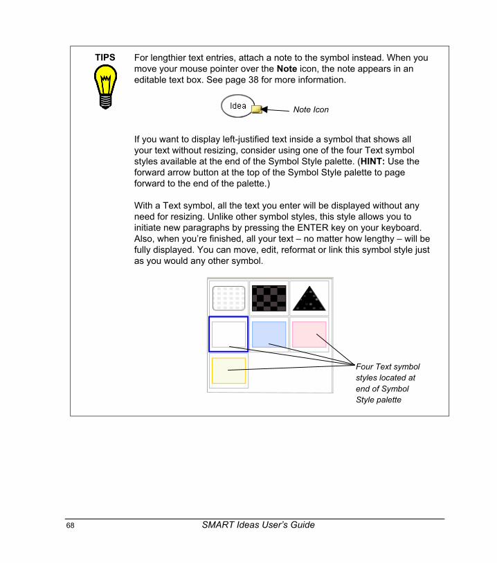
68 SMART Ideas User’s Guide
TIPS For lengthier text entries, attach a note to the symbol instead. When youmove your mouse pointer over the Note icon, the note appears in aneditable text box. See page 38 for more information.
Note Icon
If you want to display left-justified text inside a symbol that shows allyour text without resizing, consider using one of the four Text symbolstyles available at the end of the Symbol Style palette. (HINT: Use theforward arrow button at the top of the Symbol Style palette to pageforward to the end of the palette.)
With a Text symbol, all the text you enter will be displayed without anyneed for resizing. Unlike other symbol styles, this style allows you toinitiate new paragraphs by pressing the ENTER key on your keyboard.Also, when you’re finished, all your text – no matter how lengthy – will befully displayed. You can move, edit, reformat or link this symbol style justas you would any other symbol.
Four Text symbolstyles located atend of SymbolStyle palette
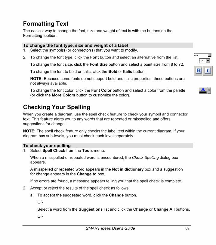
SMART Ideas User’s Guide 69
Formatting TextThe easiest way to change the font, size and weight of text is with the buttons on theFormatting toolbar.
To change the font type, size and weight of a label1. Select the symbol(s) or connector(s) that you want to modify.
2. To change the font type, click the Font button and select an alternative from the list.
To change the font size, click the Font Size button and select a point size from 8 to 72.
To change the font to bold or italic, click the Bold or Italic button.
NOTE: Because some fonts do not support bold and italic properties, these buttons arenot always available.
To change the font color, click the Font Color button and select a color from the palette(or click the More Colors button to customize the color).
Checking Your SpellingWhen you create a diagram, use the spell check feature to check your symbol and connectortext. This feature alerts you to any words that are repeated or misspelled and offerssuggestions for change.
NOTE: The spell check feature only checks the label text within the current diagram. If yourdiagram has sub-levels, you must check each level separately.
To check your spelling1. Select Spell Check from the Tools menu.
When a misspelled or repeated word is encountered, the Check Spelling dialog boxappears.
A misspelled or repeated word appears in the Not in dictionary box and a suggestionfor change appears in the Change to box.
If no errors are found, a message appears telling you that the spell check is complete.
2. Accept or reject the results of the spell check as follows:
a. To accept the suggested word, click the Change button.
OR
Select a word from the Suggestions list and click the Change or Change All buttons.
OR

70 SMART Ideas User’s Guide
Type a correction of your own in the Change to field and click the Change orChange All buttons.
b. To retain the original word (ignoring the spell check feature’s advice), click theIgnore button, or click the Ignore All button to retain every occurrence of theoriginal spelling.
c. To add the word to the Spell Check dictionary, click the Add button.
When the spell check is complete, the Check Spelling dialog box disappears.
Finding and Replacing TextWhen you need to review or change text in either the Diagram view or the Outline view, use theFind Text and Replace Text commands. Find Text helps you locate occurrences of any textyou specify. Replace Text lets you change a word or phrase throughout the diagram.
NOTE: This feature only works on the current diagram level. It won't locate and replace textthat resides in a sub-level diagram.
To find text1. Select Find Text from the Edit menu.
The Find dialog box appears.
2. Enter the text that you want to find in the Find what box.
You can type up to 255 characters in this box. The text scrolls horizontally as you type.
3. To find only separate words (not characters embedded in other words), select Matchwhole word. For example, select this option to find “run” but not “running”.
4. To find only words that have a specific pattern of uppercase and lowercase characters,select Match case.
5. Click the Find Next button.
SMART Ideas software selects the first occurrence of the text in either a symbol orconnector label.
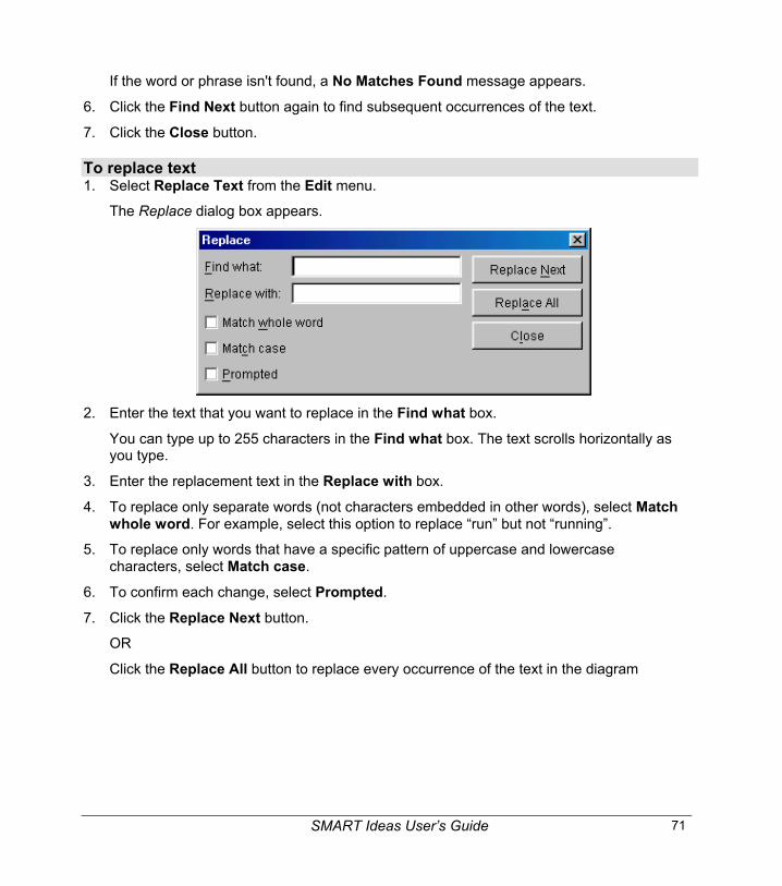
SMART Ideas User’s Guide 71
If the word or phrase isn't found, a No Matches Found message appears.
6. Click the Find Next button again to find subsequent occurrences of the text.
7. Click the Close button.
To replace text1. Select Replace Text from the Edit menu.
The Replace dialog box appears.
2. Enter the text that you want to replace in the Find what box.
You can type up to 255 characters in the Find what box. The text scrolls horizontally asyou type.
3. Enter the replacement text in the Replace with box.
4. To replace only separate words (not characters embedded in other words), select Matchwhole word. For example, select this option to replace “run” but not “running”.
5. To replace only words that have a specific pattern of uppercase and lowercasecharacters, select Match case.
6. To confirm each change, select Prompted.
7. Click the Replace Next button.
OR
Click the Replace All button to replace every occurrence of the text in the diagram

72 SMART Ideas User’s Guide
Adding Layers and Links to DiagramsYou can add depth to your diagrams by adding sub-level; you can also extend the reach ofyour diagram by adding links to local files and Web sites.
In this section, you’ll learn how to:
• create sub-levels in diagrams (page 72)
• navigate within layered diagrams (page 75)
• link any file, program, e-mail address or Web site to a symbol (page 76)
Creating Layered DiagramsEvery symbol in a diagram is a potential gateway to another diagram that you can create on asub-level of that symbol. You can use these sub-levels to illustrate or expand on information.You can also use them to hide information, so you can reveal details or examples when youwant to – or when your class is sufficiently prepared to fully understand them.
It’s easy to create a new or open an existing sub-level: Select a symbol and then click theOpen Sub-Level icon (the arrow in the upper-left corner of the symbol). The sub-level thenopens as a new, blank workspace in which you can create a diagram, write a few lines ofillustrative text, insert a picture, etc.
Click to createa sub-level
You can continue creating more sub-levels, or click the Back button (located on the left edge ofthe Standard toolbar) to return to the previous level. You can create an unlimited number ofsub-level layers to contain related symbols, diagrams, text or graphics.
Any symbol with sub-level content displays the Open Sub-level icon – even when you haven’tselected the symbol. To open a sub-level, just click this icon.
Click to open apreviously createdsub-level
For example, for a lesson on the history of the sonnet, you could create a diagram that showsthe three major types of the sonnet form.

SMART Ideas User’s Guide 73
To keep your diagram simple and clear, relegate the illustrative information – i.e., the propertiesof each sonnet type – to each symbol’s sub-level. Then, when your class is ready for moredetailed information, just click the Open Sub-level icon to view it.
For example, if you click the Open Sub-level icon on the “Petrarchan” symbol, the followingdiagram appears:
The “Petrarchan” Symbol Sub-Level
Each symbol that cites a poet also has an associated sub-level (indicated by the Sub-levelicon). These sub-levels are occupied with representative sonnets from each poet.

74 SMART Ideas User’s Guide
To create a symbol sub-level1 Select the symbol.
2 Click the Open Sub-level icon (the green, curved arrow in the top-left corner of theselection rectangle).
A new, blank workspace will open.
To return to the originating symbol (in previous layer)Click the Back button in the Standard toolbar.
OR
Click the watermark in the upper-left corner of the workspace (if it’s displayed).
Making Originating Symbols TransparentTo view the complexity of underlying diagrams at a glance, activate the Show Sublevelscommand. This command displays a miniature, ghostly image of the sub-level diagraminside the originating symbol.
When Show Sublevels is active, symbols also become functionally transparent. To move asymbol to the sub-level of another symbol, drag the symbol (or multiple connected symbols)onto the target symbol and watch the dragged symbol(s) recede and then disappear into thedestination symbol’s sub-level. Open the sub-level (by clicking the Open Sub-level icon) toview the symbol you just dropped into it.
To view small outlines of a symbol’s sub-level diagramsCheck Show Sublevels on the View menu.
A small, faint image of the sub-level diagram appears inside each originating symbol.
To drop a symbol or diagram into a sub-level1. Check Show Sublevels on the View menu and select a symbol.
NOTE: You can’t drop a selected symbol onto a sub-level if it’s connected to another symbol.
2. Move the symbol or a selected group of symbols over top of another symbol.

SMART Ideas User’s Guide 75
When the moving symbol reaches the middle of the receiving symbol, it graduallydisappears from view as it sinks into the receiving symbol's sub-level. A small, ghost-likeversion of the moved symbol appears inside the receiving symbol, and an Open Sub-level icon appears next in the upper-left corner.
3. Click the Open Sub-level icon to view the symbol you just moved.
Click here to viewthe sub-level
4. Click the Back button on the toolbar to return to the original symbol level.
Navigating through Symbol LayersBecause any symbol can have a sub-level, and any sub-level can have further sub-levels, you maylose track of where you are in a multi-layer diagram. There are a number of ways to stay oriented:
• Click the Back button on the Standard toolbar to return to a higher level, or click a symbol’sOpen Sub-level icon to see the level below.
• Click the watermark level links. You’ll notice a watermark of faint blue text links on the top-left corner of each level. Click on the different links in the watermark to return to the original(Main) level or to the other sub-levels.
Click to go to that sub-level
Current level
Click to return tothe original level
• Open the Global view (by clicking the Global tab at the bottom of the workspace) to view amap of all levels and sub-levels, and instantly access them. For a detailed discussion of theGlobal view, see page 55.
• Select View > Go To > Go Home (CTRL + HOME) to return to the originating symbol level.

76 SMART Ideas User’s Guide
Creating Links to Web Sites, Files or Other Diagram LevelsEnrich your diagram with links to any Web site or file – or just to another level in the currentdiagram. A hyperlink lets you quickly access any external sources of information to clarify,illustrate or expand on an idea that a particular symbol represents.
While you can add as many links to your diagram as you have symbols, you can create onlyone link per symbol. After you add a hyperlink to a symbol, a Link icon appears in the lower-leftcorner of that symbol. Click the icon to go directly to the associated Web site, file or diagramlevel for that link.
Link Icon
TIP Web sites are great sources for lesson materials, ideas for class projects and evennews from your local teachers’ association. Organize your favorite Web sites in amore meaningful way than a simple list of favorite sites; think about using SMARTIdeas software as a single-source file management tool: You can associate yourWeb site links with descriptive symbols in one SMART Ideas file, where they’re justa mouse click from view.
Here’s an example:
You can create a well-organized, connected diagram exclusively made up of Website links (like the one above), and even add a link to a favorite file on your harddrive or network. Either way, each time you click the Link icon, your Web browser(or Windows Explorer) opens and the associated Web site (or file) appears.

SMART Ideas User’s Guide 77
To link a symbol to a Web site1. Select a symbol.
2. Click the Link button on the Standard toolbar.
The Insert Hyperlink dialog box appears.
3. Click Web page.
4. Enter the full Web address in the box.
OR
Click the arrow and select a Web address from the list of links previously used. (This listis empty if this is the first time you’ve created a hyperlink.)
TIP Instead of manually typing a Web address into the Insert Hyperlink dialogbox, it’s easier and more accurate to just open your Web browser andnavigate to the Web site you want to link to. Now, copy the address that’s inthe Address box of your browser and paste it into the Insert Hyperlink dialogbox.
5. Click OK.

78 SMART Ideas User’s Guide
The symbol appears with a Link icon in its lower-left corner. To open the Web page thatyou just created a link to, click this icon.
Click here toopen the linkyou just created
To link a symbol to a file1. Select a symbol.
2. Click the Link button on the Standard toolbar.
The Insert Hyperlink dialog box appears.
3. Click File.
4. Click the Browse button.
The Open dialog box appears.
5. Navigate to the file that you want to link to.
6. Click the Open button.

SMART Ideas User’s Guide 79
The file path and name appear in the box.
NOTE: If the size of your file is a consideration, make sure Shortcut is selected. WithShortcut selected, the file remains on your hard drive or network, and is opened fromthat location. If you select Attachment, the file is actually attached to the SMART Ideasproject file and file size enlarges accordingly.
7. Click OK.
The symbol appears with a Link icon in its lower-left corner. To open the file that youjust created a link to, click this icon.
Click here toopen the linkyou just created
To link a symbol to another level in the same diagram1. Select a symbol.
2. Click the Link button on the Standard toolbar.
The Insert Hyperlink dialog box appears.
3. Click Level.4. Click the arrow and select a level from the list of all levels in the current SMART Ideas
file.
5. Click OK.
The symbol appears with a Link icon in its lower-left corner. To open the level youcreated a link to, click the icon.
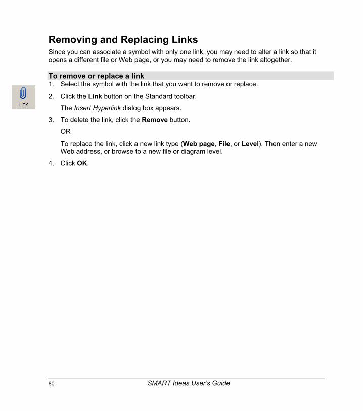
80 SMART Ideas User’s Guide
Removing and Replacing LinksSince you can associate a symbol with only one link, you may need to alter a link so that itopens a different file or Web page, or you may need to remove the link altogether.
To remove or replace a link1. Select the symbol with the link that you want to remove or replace.
2. Click the Link button on the Standard toolbar.
The Insert Hyperlink dialog box appears.
3. To delete the link, click the Remove button.
OR
To replace the link, click a new link type (Web page, File, or Level). Then enter a newWeb address, or browse to a new file or diagram level.
4. Click OK.

SMART Ideas User’s Guide 81
Working in Outline ViewNormally, you’ll work in the graphically based Diagram view, creating linked diagrams ofcolorful symbols. As you work in this view, SMART Ideas software automatically generates atext-based, hierarchically organized Outline view of the same information. This text-based viewhelps you move easily from rough ideas to a finished document.
In the figure below, note how the Diagram and Outline views show the same information indifferent ways. Only the text and idea hierarchy appear in the Outline view; none of thegraphical aspects – symbol color and shape – are apparent.
Understanding Outline ViewIn the Outline view, diagram hierarchy is conveyed by indentation and accompanying markers(a hyphen for the first subtopic level and a diamond for the second subtopic level). The result isa conventional outline of the kind typically created prior to writing any complex document.
If a symbol has an associated sub-level in the Diagram view, it appears in underlined, bold textin the Outline view. This text is a hyperlink, and, if you click it, an Outline (text-based) of thatsub-level appears.
Diagram View Outline View
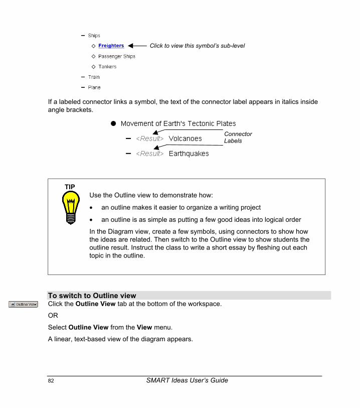
82 SMART Ideas User’s Guide
Click to view this symbol’s sub-level
If a labeled connector links a symbol, the text of the connector label appears in italics insideangle brackets.
ConnectorLabels
TIPUse the Outline view to demonstrate how:
• an outline makes it easier to organize a writing project
• an outline is as simple as putting a few good ideas into logical order
In the Diagram view, create a few symbols, using connectors to show howthe ideas are related. Then switch to the Outline view to show students theoutline result. Instruct the class to write a short essay by fleshing out eachtopic in the outline.
To switch to Outline viewClick the Outline View tab at the bottom of the workspace.
OR
Select Outline View from the View menu.
A linear, text-based view of the diagram appears.

SMART Ideas User’s Guide 83
Using the Outline View to Create ObjectsThe Outline view isn’t just for viewing a text version of your diagram. You can also createnew objects (including symbols, connectors and notes), and edit them as well. As you mightexpect, any changes that you make in the Outline view are immediately reflected in theDiagram view.
When you create a new symbol in the Outline view, it appears indented immediately belowthe selected symbol (on the next lower level of the outline hierarchy). If you don’t select asymbol, the new symbol appears at the top of the diagram hierarchy.
When you create a new connector for a symbol, that symbol automatically links to thesymbol immediately above it.
NOTE: You can create a connector only for an indented (secondary or tertiary) symbol.
To create a new symbol in Outline view1. Select the symbol that’s directly above the point where you want the new symbol to
appear.
OR
Select the main symbol if you want the symbol to appear at the top of the symbol list.
2. Click the Create New button.
Several text boxes appear.
3. Type a symbol label where you see “Enter the Symbol Text Here”.
Newly entered text
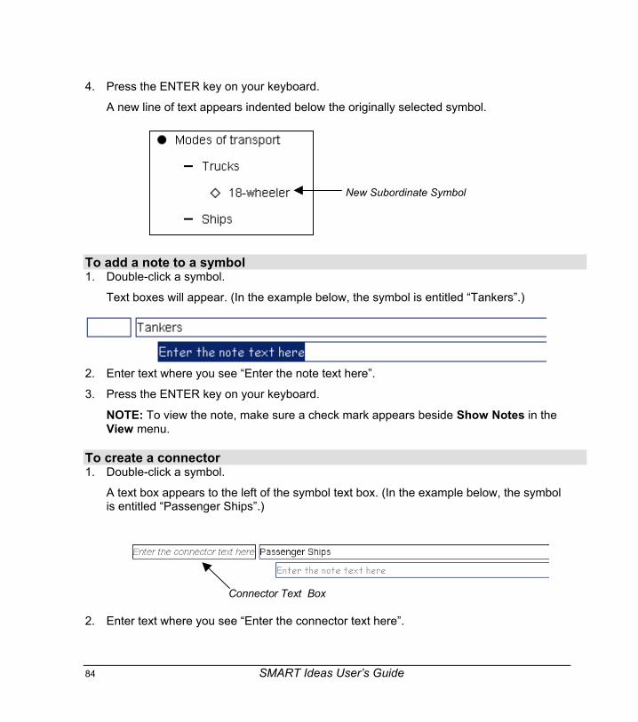
84 SMART Ideas User’s Guide
4. Press the ENTER key on your keyboard.
A new line of text appears indented below the originally selected symbol.
New Subordinate Symbol
To add a note to a symbol1. Double-click a symbol.
Text boxes will appear. (In the example below, the symbol is entitled “Tankers”.)
2. Enter text where you see “Enter the note text here”.
3. Press the ENTER key on your keyboard.
NOTE: To view the note, make sure a check mark appears beside Show Notes in theView menu.
To create a connector1. Double-click a symbol.
A text box appears to the left of the symbol text box. (In the example below, the symbolis entitled “Passenger Ships”.)
2. Enter text where you see “Enter the connector text here”.
Connector Text Box

SMART Ideas User’s Guide 85
In the Diagram view, SMART Ideas software links the selected symbol with the symbolabove it by a connector with this text label.
To edit symbol, connector or Note text1. Double-click in the line of text you want to change.
The text appears within a blue text box.
2. Revise the text as required.
3. Press the ENTER key on your keyboard.
OR
Click outside of the text box.
Reorganizing the DiagramYou can change the organization of a diagram just as easily in Outline view as you can inDiagram view. Drag a symbol to move it up or down in the hierarchy. If you drag a selectedsymbol onto another symbol that’s on a higher or lower level, the symbol that you movedappears on the same level as the destination symbol. Alternatively, you can use the Promoteand Demote buttons to change a selected symbol’s hierarchical level.
To alter the hierarchy of a diagram1. Select a symbol.
2. Click the Promote button to move the symbol up one level.
OR
Click the Demote button to move the symbol down one level.
OR
Drag the symbol over another symbol to place it on the same level as the destinationsymbol.
To cut, copy and paste symbols (and associated connectors) in Outline view1. Select a symbol.
2. Click the Cut or Copy buttons in the Standard toolbar.
OR
Select Cut or Copy from the Edit menu.
3. Click the Paste button.

86 SMART Ideas User’s Guide
OR
Select Paste from the Edit menu.
The pasted symbol appears at the top of the outline. If you like, you can drag itanywhere in the Outline view.
To delete a symbol (and associated connector)1. Select a symbol.
2. Click the Delete button in the Standard toolbar.
OR
Select Delete from the Edit or right-mouse menus.
OR
Press the DELETE key on your keyboard.

SMART Ideas User’s Guide 87
File ManagementManaging SMART Ideas software project files (IPR files) is very much like managing files inany other Windows application. For example, you can create a new file, save it for later viewingand revision, or print it.
In addition to these standard file management capabilities, there are a number of ways toexport your files so that people without SMART Ideas software can see your work. Forexample, the Export Diagram View to Web and Export Outline View to Web (Text)commands let you save the graphically based Diagram view or the text-based Outline view ofyour file in HTML format. You can then transfer the file to a Web server so anyone with a Webbrowser can access your work.
An Export to Word Document command is also available so you can save your work as aMicrosoft Word (.doc) file. Both the concept maps of the Diagram view (exported as a singlegraphical object) and the text-based Outline view (exported as fully editable bulleted lists) areexported together in the single DOC file.
SMART Ideas software also comes with numerous templates to make your work easier. Youcan also create your own custom templates for those diagrams that you find yourself usingoften.
Creating a New SMART Ideas FileWhen you create a new SMART Ideas file, you have the option of using a template or startingfrom a blank workspace.
To create a file1. Select New from the File menu.
The New SMART Ideas Diagram dialog box appears with <Blank Document>highlighted on the Templates tab.
2. If you prefer to base your new diagram on a template, select one of the templates fromthe list.
3. Click the Open button.
An untitled, blank workspace appears.
OR
If you selected a template, the template appears.

88 SMART Ideas User’s Guide
Opening a SMART Ideas FileWhen you start SMART Ideas software, the New SMART Ideas Diagram dialog box opens.You can click the Recent Files tab to access a list of all recent files. Alternatively, use theOpen command to open an .ipr file located anywhere on your hard drive or network.
If you’re working in SMART Ideas software and want to open a recently used file, click the Filemenu. You’ll see the last four SMART Ideas software project files that you worked on at thebottom of the menu. Click any one of those files to instantly load it into the workspace.
To open a file1. Select Open from the File menu.
The Open dialog box appears.
2. Under Look in, select a directory.
3. Browse to the file and select it.
OR
Type the file name in the File name box.
4. Click the Open button.
The selected file opens.
Saving a SMART Ideas FileYou can save your file to your hard drive or a network location, as you would normally.
To save a file1. For a previously saved file, select Save from the File menu to save the file in the same
format and with the same name, or click the Save button.
OR
Select Save As from the File menu to save the file with a different name or in a differentlocation.
2. If you’re saving the file for the first time, enter a file name in the Save As dialog box andthen click the Save button.

SMART Ideas User’s Guide 89
Exporting Your SMART Ideas Files to Microsoft WordIf you need to send your SMART Ideas file to someone who doesn’t have SMART Ideassoftware, just convert your file to a Microsoft Word file. When you do this, you’re not justmaking the information in your diagrams accessible to more people; you’re also transformingthe text-based Outline view into a fully editable, working outline that can serve as the basisfor a longer writing project in Word.
The two working views of SMART Ideas software – the graphically based Diagram view andthe text-based Outline view – are both displayed in the Word file. The Diagram viewappears as a single, uneditable graphic at the top of the page, while each text line in theOutline view appears as a separate, fully editable bulleted point, indented according to theoriginal symbol’s place in the diagram hierarchy.
A simple, two-level diagram would convert into a Word document as follows:
• Ideas for class projects
• Math-Science Learning Coalition
• Green Teacher Magazine
• Alberta Teachers' Association Science Council
You can edit each bulleted point, adding text to make them the lead sentence of severalconnected paragraphs, or use them as separate headings for more extended discussions.
90 SMART Ideas User’s Guide
NOTE: If the diagram has sub-levels, those sub-levels are also converted on individualpages of the resulting Word file. For example, if eight different sub-levels have been createdfrom the original, single Main page, the resulting Word file will contain nine pages. Also, thesymbols from which the sub-levels originate will appear as linked text that will take you to thesub-level when clicked.
To convert a SMART Ideas file to a Word fileSelect Export to Word Document from the File menu.
A Publishing Project message appears.
The new Microsoft Word file appears with the same file name as the SMART Ideas file and a.doc extension.
Exporting Workspace Views to the WebIt’s easy to create diagrams that you publish on the Internet or send to people who don’t haveSMART Ideas software installed on their computers. You can save your diagrams in either agraphical (Diagram view) or text-only form (Outline view) that’s ready for Web publication.
To save your diagrams in graphical form for the Internet, use the Export Diagram View toWeb command. This command saves your current diagram as a high-quality, Web-readygraphic and retains all hyperlinks in the document after conversion.
To save your diagrams to the Internet in text-only form, use the Export Outline View to Web(Text) command: This command converts the Outline view of your diagram into HTML format,ready for online publication.
To export the Diagram view for Web publication1. Select Export Diagram View to Web from the File menu.
A Saving message appears as your diagram is converted.
2. Wait a few moments.
The converted diagram opens in your Web browser.
To export the Outline view for Web publication1. Select Export Outline to Web (Text) from the File menu.
NOTE: You can be in Diagram view when you select this command. An HTML file of theOutline view only will still be created.
2. Wait a few moments.
The converted text-only outline opens in your Web browser.
SMART Ideas User’s Guide 91
Printing a DiagramYou can print the current level of your diagram or the current level plus all associated sub-levels. If you choose to print a large diagram on one page, SMART Ideas software shrinks thediagram to fit the page.
To print a SMART Ideas file1. From the File menu, select:
• Print Preview to see how your diagram will look on the printed page
• Print Current Level to print only the current level of your diagram
• Print All Levels to print every level of your diagram
The Print dialog box appears.
2. Specify the printer you want to use in the Name box.
3. Specify what you want printed in the Print range box.
4. Specify the number of copies you want printed in the Number of copies box.
5. Click OK.
Using Templates in SMART Ideas SoftwareA template is a document you can use as a pattern to create other documents of the sametype. The idea behind templates is that while you may create many documents, you generallycreate only a few types of documents. Templates provide a place to store boilerplate symbols,notes and connectors, reducing the amount of work necessary to set up new diagrams.
When you start SMART Ideas software, you’ll see a long list of templates from which tochoose. There are templates that have been specifically developed for social studies, science,language arts and lesson planning.
You can also create your own templates for diagram formats that you use frequently.
To create your own template, create a diagram as usual and save it with the .ipt extensionrather than the default .ipr (Ideas project file) extension. Selecting the .ipt extensionautomatically converts the SMART Ideas project file into a template.
For example, if you’re a language arts teacher, you might want to develop four individualtemplates that are devoted to each of the major literary archetypes – tragedy, comedy,romance and irony – with symbols that capture the generic elements of each archetypal plot.When you want to show how a particular literary work fits within the framework of a literaryarchetype, you can adapt the template using specific examples from that work.

92 SMART Ideas User’s Guide
The following example is a template developed to show recurring elements in the genre ofliterary comedy.
To use a template1. Select Open Template from the File menu.
The New SMART Ideas Diagram dialog box appears with <Blank Document> highlightedon the Templates tab.
2. Select a template from the list.
3. Click the Open button.
The template opens.
4. Customize the diagram.
5. Click the Save button.
OR
Select Save or Save As from the File menu.
The Save As dialog box opens.

SMART Ideas User’s Guide 93
6. Give your diagram a name, navigate to a folder and click the Save button. By default,SMART Ideas software gives the file an .ipr (Ideas project) extension.
To create your own template1. Create a new diagram.
OR
Open an existing diagram that you want to develop into a template.
2. Select Save As from the File menu.
The Save As dialog box opens.
3. Type a name for the diagram and include an .ipt extension.
4. Click the Save button.
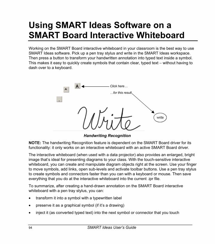
94 SMART Ideas User’s Guide
Using SMART Ideas Software on aSMART Board Interactive WhiteboardWorking on the SMART Board interactive whiteboard in your classroom is the best way to useSMART Ideas software. Pick up a pen tray stylus and write in the SMART Ideas workspace.Then press a button to transform your handwritten annotation into typed text inside a symbol.This makes it easy to quickly create symbols that contain clear, typed text − without having todash over to a keyboard.
Click here…
…for this result
Handwriting Recognition
NOTE: The handwriting Recognition feature is dependent on the SMART Board driver for itsfunctionality: it only works on an interactive whiteboard with an active SMART Board driver.
The interactive whiteboard (when used with a data projector) also provides an enlarged, brightimage that’s ideal for presenting diagrams to your class. With the touch-sensitive interactivewhiteboard, you can create and manipulate diagram objects right at the screen. Use your fingerto move symbols, add links, open sub-levels and activate toolbar buttons. Use a pen tray stylusto create symbols and connectors faster than you can with a keyboard or mouse. Then saveeverything that you do at the interactive whiteboard into the current .ipr file.
To summarize, after creating a hand-drawn annotation on the SMART Board interactivewhiteboard with a pen tray stylus, you can:
• transform it into a symbol with a typewritten label
• preserve it as a graphical symbol (if it’s a drawing)
• inject it (as converted typed text) into the next symbol or connector that you touch

SMART Ideas User’s Guide 95
• move it (by itself or with a group of symbols)
• edit object labels in Outline view
• delete it
Creating Symbols with a Pen Tray StylusFor speed and ease of diagram creation, nothing beats working on a SMART Board interactivewhiteboard. Keep your keyboard and mouse out of the way: Use the Pen Tray stylus to createsymbols (as described below), and then use your finger to change their appearance byactivating the buttons and menus of SMART Ideas software right at the screen.
You can convert your handwriting into conventional typewritten symbols or use it as is − ahandwritten graphical symbol.
NOTE: If your computer isn’t connected to an interactive whiteboard, but you are runningSMART Board software, select Pen from the Tools menu, and you can then use your mouse tocreate handwritten annotations.
To create a typed symbol with a stylus1. Pick up a pen tray stylus.
2. Write on the interactive whiteboard.
Three buttons appear to the left of your annotation.
Convert to typed text
Preserve drawingas a graphicalsymbol
Inject converted textinto next objecttouched
3. Without replacing the stylus in the pen tray, press the Convert to Typed Text button.
The text appears inside a symbol in the currently selected style.
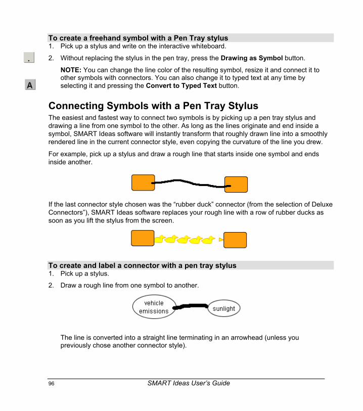
96 SMART Ideas User’s Guide
To create a freehand symbol with a Pen Tray stylus1. Pick up a stylus and write on the interactive whiteboard.
2. Without replacing the stylus in the pen tray, press the Drawing as Symbol button.
NOTE: You can change the line color of the resulting symbol, resize it and connect it toother symbols with connectors. You can also change it to typed text at any time byselecting it and pressing the Convert to Typed Text button.
Connecting Symbols with a Pen Tray StylusThe easiest and fastest way to connect two symbols is by picking up a pen tray stylus anddrawing a line from one symbol to the other. As long as the lines originate and end inside asymbol, SMART Ideas software will instantly transform that roughly drawn line into a smoothlyrendered line in the current connector style, even copying the curvature of the line you drew.
For example, pick up a stylus and draw a rough line that starts inside one symbol and endsinside another.
If the last connector style chosen was the “rubber duck” connector (from the selection of DeluxeConnectors”), SMART Ideas software replaces your rough line with a row of rubber ducks assoon as you lift the stylus from the screen.
To create and label a connector with a pen tray stylus1. Pick up a stylus.
2. Draw a rough line from one symbol to another.
The line is converted into a straight line terminating in an arrowhead (unless youpreviously chose another connector style).

SMART Ideas User’s Guide 97
NOTE: If you prefer to draw a curved line, SMART Ideas software duplicates the curveyou’ve drawn.
3. Write some connector label text anywhere in the workspace.
4. Press the Inject into Object button.
5. With the stylus, touch the connector that you want to label.
The connector displays the text label you just wrote.
To create a quickly connected (and labeled) diagram with a pen tray stylus1. Draw a line emerging from any symbol.

98 SMART Ideas User’s Guide
A connected, blank symbol (in the current symbol style) appears at the end of the line.
2. Write a label for the blank symbol anywhere in the workspace.
3. Press the Inject into Object button.
4. Touch the symbol with your stylus.
The symbol displays the text label that you just wrote.
Editing with a Pen Tray StylusUse a pen tray stylus to edit the label for any symbol or connector in your diagram. While youcan’t selectively edit the letters or numbers inside a symbol or connector label, you can easilyreplace the entire label using the Inject into Object function.
You also don’t need a keyboard to enter or edit text in the Outline view, and you can edit moreselectively than you can in the Diagram view. Just pick up a stylus, position the cursor whereyou want to add or edit object text and then write in the text box.
To edit an object label with a pen tray stylus (in the Diagram view)1. Pick up a stylus and write the replacement text anywhere in the SMART Ideas
workspace.
2. Without replacing the stylus, press the Inject into Object button.
3. Press the object (either a symbol or a connector) that contains the text that you wantreplaced.
Your handwritten text becomes the new typed text label for the selected object.

SMART Ideas User’s Guide 99
To edit an object label with a pen tray stylus (in Outline view)1. Pick up a stylus and double-press on a symbol or connector label.
A freehand writing area appears, with three buttons on the left side.
2. Select the text that you want to change or delete.
OR
Position the cursor at the insertion point where you want to add text.
3. To add new text or change the selected text, write in the freehand writing area.
4. Press the Convert to Typed Text button.
Symbol Label
Freehand Writing Area
Text insertion point
Convert totyped text
Insert a space
Delete highlightedcharacter
Write here!
Text insertion point
Write additional textand press theConvert to TypedText button
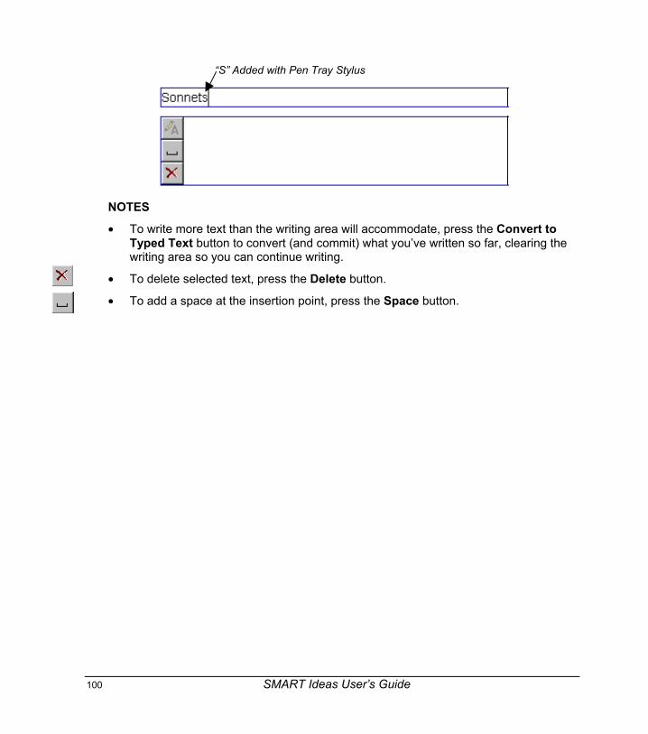
100 SMART Ideas User’s Guide
“S” Added with Pen Tray Stylus
NOTES
• To write more text than the writing area will accommodate, press the Convert toTyped Text button to convert (and commit) what you’ve written so far, clearing thewriting area so you can continue writing.
• To delete selected text, press the Delete button.
• To add a space at the insertion point, press the Space button.

SMART Ideas User’s Guide 101
Customer SupportSMART’s Technical Support team welcomes your call. However, you may first want tocontact your local reseller if you experience any difficulty with SMART Ideas software, asthey may be able to solve the problem without delay.
All SMART products include free telephone, fax and e-mail support.Telephone: 1.866.518.6791 (toll-free in Canada/U.S) or +1.403.228.5940 (all other countries)
(Available 7 a.m. − 6 p.m. Mountain time from Monday to Friday)Fax: +1.403.806.1256E-mail: [email protected] Site: www.smarttech.com/support
The support representative may ask you for the version of the software that’s causing theproblem and the version of your computer’s operating system.General Inquiries
Main Switchboard: 1.888.42.SMART (toll-free in Canada/U.S.) or +1.403.245.0333(all other countries)
Fax: +1.403.228.2500E-mail: [email protected]: SMART Technologies Inc.
Suite 600, 1177 – 11th Avenue SWCalgary, AB CANADA T2R 1K9
Registration
A User Registration card was included with SMART Ideas software. To help us serve you, fillin and mail this card to SMART Technologies Inc. or register online atwww.smarttech.com/registration.

102 SMART Ideas User’s Guide
Appendix A: Using SMART Ideas ServerSoftwareIf you’re working with SMART Ideas server software, you’ll have the option of sharing yourSMART Ideas file online and collaborating in real time with other users. And, since SMARTIdeas server software works in conjunction with a Web server, your team can be located in thesame office or all over the world. You can not only create and manipulate objectscollaboratively, you can use the Chat feature to write text messages at the same time.
When you’re working online, your file is simply known as a project. Although a project isaccessible to other server users, many security features are available to protect sensitiveinformation. You can specify who is allowed access to your project, and even which symbolsyou want other team members to view or edit.
Users can work in the same or different areas (or levels) of a project without interrupting thework of others. However, if you’re conferencing with other users, you may want the group tofollow along as you navigate to different project areas and sub-levels. SMART Ideas softwarehas an easy-to-use Follow Me feature that’s ideal for this purpose. Of course, if you prefer towork on a diagram privately, you can work from your hard drive, and then upload the project tothe server when you’re ready to share it.
As changes are made, projects are updated instantly on the SMART Ideas software server, sochanges are immediately visible to all users. But you aren’t restricted to viewing what otherusers are doing in real time: You can also view changes to the project that occurred after youlogged off.
With SMART Ideas server software, you can:
• Configure security features (page 103)
• Connect to the server (page 103)
• Open a project (page 104)
• Create a project (page 104)
• Upload and download projects to the server (page 105)
• Restrict access to projects and objects within projects (page 106)
• Share your view with others (page 107)
• Chat with other project users (page 108)
SMART Ideas User’s Guide 103
• Receive e-mail notification of newly joined project members and project changes (page110)
• Delete a project (page 112)
• Disconnect from the server (page 112)
Server Security OverviewSMART Ideas server software offers a secure online environment for even the most sensitiveproject material. All security is based on your network login name and password. When youruser identification has been established, SMART Ideas server software determines if your levelof access is appropriate for the task you want to perform.
There are four user categories for SMART Ideas server software:
AdministratorsAdministrators maintain and have full access to all SMART Ideas server software files.Administrators can create guest accounts and limit which users can be designated asproject owners.
OwnersIf you create a project, you are the owner of that project. You can add and delete users,grant co-owner status to selected users and delete the project from the server.
UsersA user is anyone who is logged on to the SMART Ideas server software. Users can openonly those projects to which they’ve been granted access, but they have both read and writeprivileges to these projects. Those users without access will not see that project title listed inthe Project Manager.
GuestsGuests have neither an individual login name nor a password. An administrator must set up ageneral guest account for temporary use. Once logged in, guests have the same read and writeprivileges as any other user.
Connecting to the ServerTo share your diagrams with other users, you must first connect to SMART Ideas serversoftware.

104 SMART Ideas User’s Guide
To connect to SMART Ideas server software1. Select Tools > Online > Go Online.
The Connect to Server dialog box appears.
2. Enter the server URL address in Location (URL). If unknown, contact your SMARTIdeas Software Administrator for the correct address.
3. Enter the same User name and Password that you use to sign on to your network.
4. Click the Connect button.
The Project Manager dialog box appears, with a list of all the SMART Ideas softwarethat projects you can access on this server.
Opening a ProjectThe Project Manager displays a list of all those projects that you either own or have permissionto access. If the project you want to open is located on a different server, you’ll need todisconnect from the current server and then connect to the other server.
To open a project1. Connect to the server (see the previous procedure).
OR
If you're already connected the server, select Tools > Online > Open Project.The Project Manager dialog box appears.
2. Select a project from the project list.
3. Click the Open button.
Creating a ProjectWhen you’re connected to SMART Ideas server software, you can create a project on theserver or by uploading an existing SMART Ideas file from your hard drive.
To create a project1. Open the Project Manager, either by connecting to the server (see page 103) or by
selecting Tools > Online > Open Project.The Project Manager dialog box appears.
2. Click the New button.
A Create New Project dialog appears.
SMART Ideas User’s Guide 105
3. Enter a name for the new project.
4. Click OK.
A new, blank SMART Ideas workspace appears. The project name will also appear inthe project list of your Project Manager.
5. Select the users with whom you want to share the new project (see page 106).
To upload a SMART Ideas diagram as a new project1. Select Tools > Online > Upload New Project.
The Open dialog box appears.
2. Browse to the .ipr file that you want to upload and select it.
3. Click the Open button.
An Uploading Project message appears. This process may take a few moments.Another message informs you when the project is available online.
4. Click the Close button.
The uploaded project appears.
5. Select the users with whom you want to share the new project (see page 106).
Downloading a Project to Your Hard Drive/UploadingBack to the ServerAfter working on a project on a server, you may want to continue developing your ideas from alocal hard drive. Or you may be on the road with your laptop and want to work on a projectwhile you’re away.
It’s easy to download a project, work on it as an offline .ipr file and then upload it to the server,merging the original project with your revision. Any changes you made to the offline file willappear in the project after the merge.
To download a project to your hard drive1. When online, select Save As from the File menu.
The Save As dialog box appears.
2. Select your hard drive in the Save in box.
3. Enter a name in the File name box.
4. Click the Save button.
The newly created .ipr file is now available to use offline.

106 SMART Ideas User’s Guide
To merge a previously downloaded project1. Connect to the server and open the project into which you want to merge your SMART
Ideas file (see page 94).
2. Upload the .ipr file to the server (see page 105).
3. Select Tools > Online > Upload New Project.The Open dialog box appears.
4. Browse to the project that you want to merge with the current project and select it.
5. Click the Open button.
Your changes are added to the server-resident project.
Controlling Project AccessIf you create a project, you are the project owner, and ,as such, you control access to theproject. When you create a new project in SMART Ideas server software, or at any time in thelife of a project you own, you may want to restrict or expand access to it. You also have theoption of allowing unlimited user access to your project.
To expand access to your project1. Select Tools > Online > Project Administration.
The Project Administration dialog box opens with a list of all projects on the server.
2. Scroll to the project, select it, and click the Properties button.
NOTE: If you aren’t the owner of the selected project, the Properties button is grayedout (inactive).
The Project dialog box opens with a list of all available SMART Ideas software serverusers.
3. To add a user, click the Users tab, select a user's ID from the list, and click the Addbutton.
OR
To add all available users, select Make this project visible to all users.OR
To add an owner, click the Owners tab, select a user's ID from the list, and click theAdd button.
NOTE: If you make a user a co-owner, that individual can add and remove users fromthe Users tab, and delete the project from the server.

SMART Ideas User’s Guide 107
4. Click OK.
To remove access to your project1. Select Tools > Online > Project Administration.
The Project Administration dialog box opens.
2. Scroll to the project, select it, and click the Properties button.
The Project dialog box opens.
3. To remove access for a project owner, select the Owners tab.
4. Select a user’s ID from the list.
5. Click the Remove button.
6. Click OK.
Sharing Your View with Other Project MembersKeep up with your collaboration partners working on online projects by ensuring you’re alwayssharing the same view. Use the Follow Me command to keep everyone focused in the samearea of the project.
With this feature activated, the user with mouse control is the temporary project leader, and theview for all other project members will change to correspond to the leader’s view. If the leaderopens a symbol sub-level, for example, this same sub-level becomes the current view for allother project members.
To share your view with others1. Go online and open the same project as the rest of your group.
2. Select Tools > Online > Follow Me.
3. Ensure other group members also select Tools > Online > Follow Me.
Any group member who assumes mouse control determines the current view of theentire group.

108 SMART Ideas User’s Guide
Chatting with Other Project MembersTrue collaboration means actively communicating with others while you’re working on a project.The Chat command lets you collaborate fully: When you’re online you can send and receivemessages privately with individual project members or with the entire group.
You can keep the lines of communication open throughout your group session. The Chat dialogbox can stay on top, even when you move to symbol sub-levels.
To chat with all project members1. Select Tools > Online > Chat.
OR
Select Tools > Online > List Projects and Users.
The Project and User List dialog box appears.
Server
Project (Select forGroup Chat)
Click here
2. Select a project listed under the server and click the Project Chat button.
The Chat dialog box appears.

SMART Ideas User’s Guide 109
Project Name
Record of ChatMessages
Text-Entry Area
3. Enter your message in the white text-entry area at the bottom of the dialog box.
4. Press the ENTER key on your keyboard to send the text to other project members.
SMART Ideas server software adds your message to the chat message record at thetop of the dialog.
NOTE: Other project members must have the Chat dialog box open to see yourmessage. If a member opens the Chat dialog box after you’ve sent a message, theywon’t see that message.
5. To terminate the chat session, click the Close button in the upper-right corner of thedialog box.
To chat one-on-one with another project member1. Select Tools > Online > List Projects and Users.
The Project and User List dialog box appears.
2. Select a user's name.
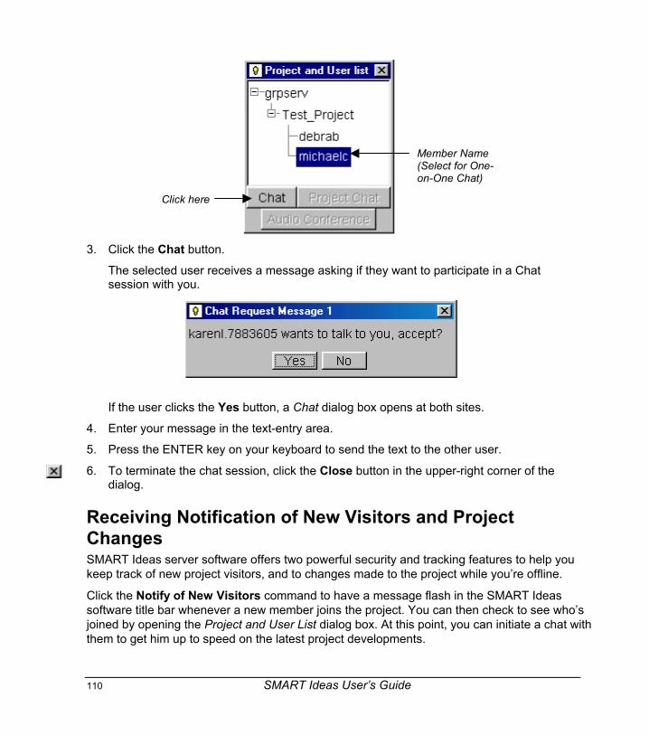
110 SMART Ideas User’s Guide
Member Name(Select for One-on-One Chat)
Click here
3. Click the Chat button.
The selected user receives a message asking if they want to participate in a Chatsession with you.
If the user clicks the Yes button, a Chat dialog box opens at both sites.
4. Enter your message in the text-entry area.
5. Press the ENTER key on your keyboard to send the text to the other user.
6. To terminate the chat session, click the Close button in the upper-right corner of thedialog.
Receiving Notification of New Visitors and ProjectChangesSMART Ideas server software offers two powerful security and tracking features to help youkeep track of new project visitors, and to changes made to the project while you’re offline.
Click the Notify of New Visitors command to have a message flash in the SMART Ideassoftware title bar whenever a new member joins the project. You can then check to see who’sjoined by opening the Project and User List dialog box. At this point, you can initiate a chat withthem to get him up to speed on the latest project developments.

SMART Ideas User’s Guide 111
If you’re offline for a while, you may want to be notified via e-mail when changes to the projecthave been made by other group members. You can even arrange to be e-mailed with news ofexactly which symbols have been changed.
To receive notification of newly joined project members1. Check Notify of New Visitors on the Tools > Online menu.
When a new member joins the project, the title bar flashes with the following message:
2. To see who’s joined, select Tools > Online > List Projects and Users.
3. To initiate a chat, select the new user’s name and click the Chat button.
To receive e-mail notifications of project changes1. Select Tools > Online > E-Mail Notification.
The E-Mail Notification dialog box appears.
2. Select the project from the list on the left side of the dialog box.
3. Click the Add button.
The project name appears in the list on the right side of the dialog box.
4. Enter your e-mail address in the E-mail Address box.
5. Click OK.
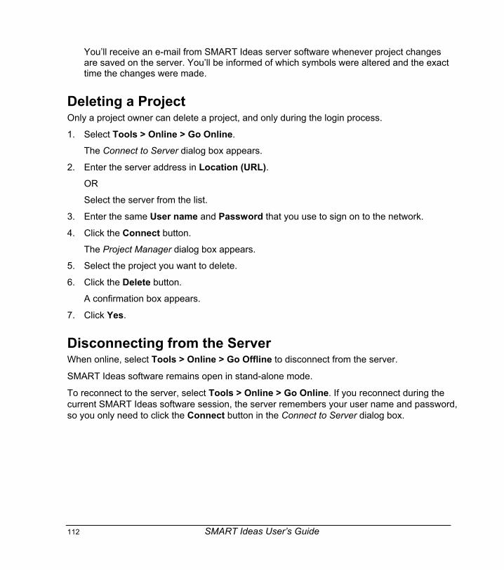
112 SMART Ideas User’s Guide
You’ll receive an e-mail from SMART Ideas server software whenever project changesare saved on the server. You’ll be informed of which symbols were altered and the exacttime the changes were made.
Deleting a ProjectOnly a project owner can delete a project, and only during the login process.
1. Select Tools > Online > Go Online.
The Connect to Server dialog box appears.
2. Enter the server address in Location (URL).OR
Select the server from the list.
3. Enter the same User name and Password that you use to sign on to the network.
4. Click the Connect button.
The Project Manager dialog box appears.
5. Select the project you want to delete.
6. Click the Delete button.
A confirmation box appears.
7. Click Yes.
Disconnecting from the ServerWhen online, select Tools > Online > Go Offline to disconnect from the server.
SMART Ideas software remains open in stand-alone mode.
To reconnect to the server, select Tools > Online > Go Online. If you reconnect during thecurrent SMART Ideas software session, the server remembers your user name and password,so you only need to click the Connect button in the Connect to Server dialog box.

SMART Ideas User’s Guide 113
Appendix B: License AgreementPlease read this License Agreement (“Agreement”) carefully. This is a legal agreementbetween you (the "Licensee") and SMART Technologies Inc. ("SMART") for SMART Ideasconcept-mapping software and accompanying documentation (collectively, the "Software").
This Agreement provides important information concerning the Software, provides Licenseewith a non-exclusive and non-transferable license to install and use the Software and containswarranty and liability information. By first installing and using the Software, you, on behalf ofLicensee, are accepting the Software and agreeing to become bound by the terms of thisAgreement. By so installing and using, you acknowledge that you have the authority to bindLicensee to the terms of this Agreement. If you do not have such authority or you, on behalf ofLicensee, do not otherwise agree to be bound by the terms of this Agreement, do not install oruse the Software.
1. Grant of License
Subject to payment of the applicable license fees, SMART grants Licensee a non-exclusive,non-transferable license to install and use the Software and accompanying documentation asfollows:
(a) Licensee may install and use the Software on that number of desktop computersrecorded on the Sales Order Confirmation that is sent by electronic means toLicensee on account of (i) original purchase; or (ii) purchase of additional Softwarelicenses, as the case may be;
(b) Licensee may transfer the Software to another desktop computer provided that itis removed from the desktop computer from which it is transferred;
(c) if Licensee is an educational institution, its teaching and academic staff may eachmake one (1) copy of the Software on their own personal computers for purposesdirectly related to their teaching and academic duties at the educational institution;
(d) any copying of the Software is prohibited unless in accordance with Section 1(c) ofthis Agreement or unless for back-up or archival purposes in which case one(1)copy may be made; and
(e) Licensee may copy the documentation, without change, as necessary to fullyutilize the Software, provided the copies contain all the original proprietary notices.
Any attempt by Licensee to install or use the Software on desktop computers in excess of thenumber actually purchased and licensed by Licensee is a breach of this Agreement.
2. Restrictions

114 SMART Ideas User’s Guide
All rights not expressly granted are reserved by SMART. Licensee may not:
(a) may not commercially distribute copies of the Software;
(b) may not modify, enhance, adapt, vary or create derivative works based on theSoftware;
(c) may not reverse engineer, reverse compile, disassemble, translate, decompile,disassemble or otherwise attempt to derive source code from (or the underlyingideas, algorithms, structure or organization of) the Software, for any purpose,including for the purpose of discovering any aspect of the technology inherenttherein. Licensee may undertake such activities only to the extent that suchactivity is expressly and strictly permitted by applicable law notwithstanding theforegoing limitation, and then only for the purpose of achieving inter-operability ofother independently developed computer programs;
(d) may not rent, lease, sublicense, distribute or supply the Software to any otherparty
(e) must comply with all applicable laws regarding the use of the Software; and
(f) must maintain all trademark and copyright notices on all copies of the Software.
3. Support Services
SMART may provide Licensee with support services (“Support Services”) related to theSoftware in its discretion. Use of Support Services, if any, is governed by the SMART policiesand programs described in the user guide, online documentation and/or other SMART-providedmaterials as modified by SMART from time to time. Any supplemental software provided toLicensee as part of Support Services shall be considered part of the Software and is subject tothe terms of this Agreement.
4. Replacement, Modification and Upgrade of the Software
SMART reserves the right to replace, modify or upgrade the Software at any time by offeringLicensee a replacement or modified version of the Software and to charge Licensee for suchreplacement, modification or upgrade. Any such replacement or modified Software or upgradeto the Software, or any component thereof, offered to Licensee by SMART shall be consideredpart of the Software and subject to the terms of this Agreement. In the event SMART offers areplacement or modified version of or upgrade to the Software (a) Licensee’s continued use ofthe Software is conditioned on Licensee’s acceptance of such replacement or modified versionof or upgrade to the Software and any accompanying superceding end-user license agreementand (b) in the case of the replacement or modified Software, Licensee’s use of all prior versionsof the Software is terminated.

SMART Ideas User’s Guide 115
5. Termination
Without prejudice to any other rights, SMART may terminate this Agreement if Licensee fails tocomply with the terms and conditions of this Agreement. In such event, Licensee mustimmediately stop using the Software, destroy all copies of the Software and all of its componentparts, and upon request, provide an affidavit certifying Licensee’s compliance with theforegoing.
6. Copyright
All right, title and copyright in and to the Software any copies thereof are owned by SMART orits suppliers. All title and intellectual property rights in and to the content which may beincorporated through use of the Software is the property of the respective content owner andmay be protected by applicable copyright or other intellectual property laws and treaties. ThisAgreement grants Licensee no rights to use such content.
7. Export Restrictions
Licensee agrees that it will not export or re-export the Software, or any component thereof, orany process or service that is the direct product of the Software (the foregoing collectivelyreferred to as the "Restricted Components") to any country, person or entity subject toCanadian or U.S. export restrictions. Licensee specifically agrees not to export or re-exportany of the Restricted Components (i) to any country to which Canada or the US hasembargoed or restricted the export of goods or services or to any national of such country,wherever located, who intends to transmit or transport the Restricted Components back to suchcountry (ii) to any person or entity who Licensee knows or has reason to know will utilize theRestricted Components in the design, development or production of nuclear, chemical orbiological weapons, or (iii) to any person or entity who has been prohibited from participating inCanadian or US export transactions by any official body of the Canadian or US government.Licensee warrants and represents that no official of the Canadian or US government hassuspended, revoked or denied its export privileges.
8. US Government Restricted Rights
All components of the Software provided to the U.S. government pursuant to solicitationsissued on or after December 1, 1995 is provided with the commercial rights and restrictionsdescribed elsewhere herein. All components of the Software provided to the U.S. governmentpursuant to solicitations issued prior to December 1, 1995 is provided with Restricted Rights asprovided for in FAR, 48 CFR 52.227-14 (June 1987) or DFAR's, 48 CFR 252.227-7013(October 1988), as applicable.
9. NO WARRANTY
ANY USE OF THE SOFTWARE IS AT LICENSEE’S OWN RISK. TO THE MAXIMUMEXTENT PERMITTED BY APPLICABLE LAW, SMART AND ITS SUPPLIERS DISCLAIM ALL

116 SMART Ideas User’s Guide
WARRANTIES AND CONDITIONS, EITHER EXPRESSED OR IMPLIED, INCLUDING, BUTNOT LIMITED TO, IMPLIED WARRANTIES OF MERCHANTABILITY, FITNESS FOR APARTICULAR PURPOSE, TITLE AND NONINFRINGEMENT WITH REGARD TO THESOFTARE, AND THE PROVISION OF OR FAILURE TO PROVIDE SUPPORT SERVICES.THIS LIMITED WARRANTY GIVES LICENSEE SPECIFIC LEGAL RIGHTS. LICENSEE MAYHAVE OTHERS, WHICH VARY FROM JURISDICTION TO JURISDICTION.
10. NO LIABILITY FOR CONSEQUENTIAL DAMAGES
TO THE MAXIMUM EXTENT PERMITTED BY APPLICABLE LAW, IN NO EVENT SHALLSMART OR ITS SUPPLIERS OR LICENSORS BE LIABLE FOR ANY SPECIAL, INCIDENTAL,INDIRECT, CONSEQUENTIAL OR PUNITIVE DAMAGES WHATSOEVER (INCLUDING,WITHOUT LIMITATION, DAMAGES FOR ANY INJURY TO ANY PERSON OR PROPERTY,DAMAGES FOR LOSS OF BUSINESS PROFITS, BUSINESS INTERRUPTION, LOSS OFBUSINESS INFORMATION, LOSS OF PRIVACY, DAMAGES FOR FAILURE TO MEET ANYDUTY INCLUDING THE DUTIES OF GOOD FAITH OR OF REASONABLE CARE, FORNEGLIGENCE OR ANY OTHER PECUNIARY LOSS) ARISING OUT OF THE USE OF ORINABILITY TO USE THE SOFTWARE OR THE PROVISION OF OR FAILURE TO PROVIDESUPPORT SERVICES, WHETHER BASED ON CONTRACT, TORT, NEGLIGENCE, STRICTLIABILITY OR OTHERWISE, EVEN IF SMART OR ANY SUPPLIER OR LICENSOR OFSMART HAS BEEN ADVISED OF THE POSSIBILITY OF SUCH DAMAGES. BECAUSESOME JURISDICTIONS DO NOT ALLOW THE EXCLUSION OR LIMITATION OF LIABILITY,THE ABOVE LIMITATION MAY NOT APPLY TO LICENSEE.
11. LIMITATION OF LIABILITY
IN ANY CASE, SMART'S ENTIRE LIABILITY AND LICENSEE’S EXCLUSIVE REMEDYUNDER THIS AGREEMENT SHALL NOT EXCEED TEN DOLLARS (CAD $10.00).
12. SMART'S Suppliers and Licensors
Any release, disclaimer or limitation of SMART’s liability or damages pursuant to thisAgreement shall be construed, in addition to SMART's benefit, also to the benefit of SMART'ssuppliers, licensors, employees and contractors, and without limiting any other defenses thatsuch suppliers, licensors, employees and contractors may have, Licensee agrees to releasesuch parties from liability or damages in accordance with such release, disclaimer or limitationof liability or damages to the same extent that such provisions apply to SMART.
13. Confidentiality
Licensee acknowledges that the Software embodies confidential information of SMART and/orits suppliers and licensors. To the extent Licensee has access to any such information,Licensee agrees to use such information only for the authorized use of the Software. Licenseefurther agree not to disclose such confidential information to any other party and to use at least

SMART Ideas User’s Guide 117
the same degree of care to maintain the confidential nature of such information as Licenseeuses to maintain the confidentiality of its own confidential information.
14. Injunctive Relief
Licensee acknowledges that, in the event Licensee breaches any provision of this Agreement,SMART will not have an adequate remedy in money or damages. SMART shall therefore beentitled to obtain an injunction against such breach from any court of competent jurisdictionimmediately upon request without posting bond. SMART's right to obtain injunctive relief shallnot limit its right to seek further remedies.
15. Modifications
No modification of this Agreement shall be binding unless it is in writing and is signed by anauthorized representative of the party against whom enforcement of the modification is sought.
16. Governing Law
This Agreement is governed by the laws of the Province of Alberta, Canada. Also to the extentpermitted by applicable law, the parties irrevocably agree that any litigation involving thisAgreement or the Software shall be brought in the provincial courts in the Province of Alberta orthe federal courts of Canada, as the case may be. Licensee agrees that it shall not assert anyclaim that it is not subject to the jurisdiction of such courts, that the venue is improper, that theforum is inconvenient or any similar objection, claim or argument.
17. Entire Agreement
This Agreement constitutes the entire understanding and agreement of the parties andsupercedes any and all prior or contemporaneous representations, understandings andagreements between the parties with respect of the subject matter of this Agreement. If anyprovision of this Agreement is held invalid, the remainder of this Agreement shall continue infull force and effect.
18. Waiver
The failure by a party to exercise any right hereunder shall not operate as a waiver of suchparty's right to exercise such right or any other right in the future.
QUESTIONS
Should you have any questions concerning this Agreement, or if you desire to contact SMARTfor any reason, please write:
SMART Technologies Inc. 600, 1177-11th Avenue SW, Calgary, AB Canada T2R 1K9.
SMART Ideas is a registered trademark of SMART Technologies Inc. in Canada and the U.S.SMART Ideas is a trademark of SMART Technologies Inc. in other jurisdictions.

118 SMART Ideas User’s Guide
Java(tm) Runtime Environment
Version 1.1.6
Binary Code License
This binary code license ("License") contains rights and restrictions associated with use of theacLicenseeing Java Runtime Environment software and documentation ("Software"). Read theLicense carefully before using the Software. By using the Software you agree to the terms andconditions of this License.
1. License to Distribute. Licensee is granted a royalty-free right to reproduce and distribute theSoftware provided that Licensee:
(i) distributes the Software complete and unmodified (except for the specific files identified asoptional in the Software README file), only as part of, and for the sole purpose of running,Licensee's Java compatible applet or application ("Program") into which the Software isincorporated;
(ii) does not distribute additional software intended to replace any component(s) of theSoftware;
(iii) agrees to incorporate the most current version of the Software that was available 180 daysprior to each production release of the Program;
(iv) does not remove or alter any proprietary legends or notices contained in the Software;
(v) includes the provisions of Sections 2, 3, 5, 6, 8 and 9 in Licensee's license agreement forthe Program; and
(vi) agrees to indemnify, hold harmless, and defend Sun and its licensors from and against anyclaims or lawsuits, including attorneys' fees, that arise or result from the use or distribution ofthe Program.
2. Java Platform Interface. Licensee may not modify the Java Platform Interface ("JPI",identified as classes contained within the "java" package or any subpackages of the "java"package), by creating additional classes within the JPI or otherwise causing the addition to ormodification of the classes in the JPI. In the event that Licensee creates any Java-related APIand distributes such API to others for applet or application development, Licensee mustpromptly publish broadly, an accurate specification for such API for free use by all developersof Java-based software.
3. Restrictions. Software is confidential copyrighted information of Sun and title to all copies isretained by Sun and/or its licensors. Licensee shall not decompile, disassemble, decrypt,extract, or otherwise reverse engineer Software. Software may not be leased, assigned, orsublicensed, in whole or in part, except as specifically authorized in Section 1. Software is notdesigned or intended for use in online control of aircraft, air traffic, aircraft navigation or aircraft

SMART Ideas User’s Guide 119
communications; or in the design, construction, operation or maintenance of any nuclearfacility. Licensee warrants that it will not use or redistribute the Software for such purposes.
4. Trademarks and Logos.This License does not authorize Licensee to use any Sun name,trademark or logo. Licensee acknowledges that Sun owns the Java trademark and all Java-related trademarks, logos and icons including the Coffee Cup and Duke ("Java Marks") andagrees to:
(i) comply with the Java Trademark Guidelines at http://java.sun.com/trademarks.html;
(ii) not do anything harmful to or inconsistent with Sun's rights in the Java Marks; and
(iii) assist Sun in protecting those rights, including assigning to Sun any rights acquired byLicensee in any Java Mark.
5. Disclaimer of Warranty. Software is provided "AS IS," without a warranty of any kind. ALLEXPRESS OR IMPLIED REPRESENTATIONS AND WARRANTIES, INCLUDING ANYIMPLIED WARRANTY OF MERCHANTABILITY, FITNESS FOR A PARTICULAR PURPOSEOR NON-INFRINGEMENT, ARE HEREBY EXCLUDED.
6. Limitation of Liability. SUN AND ITS LICENSORS SHALL NOT BE LIABLE FOR ANYDAMAGES SUFFERED BY LICENSEE OR ANY THIRD PARTY AS A RESULT OF USING ORDISTRIBUTING SOFTWARE. IN NO EVENT WILL SUN OR ITS LICENSORS BE LIABLEFOR ANY LOST REVENUE, PROFIT OR DATA, OR FOR DIRECT, INDIRECT, SPECIAL,CONSEQUENTIAL, INCIDENTAL OR PUNITIVE DAMAGES, HOWEVER CAUSED ANDREGARDLESS OF THE THEORY OF LIABILITY, ARISING OUT OF THE USE OF ORINABILITY TO USE SOFTWARE, EVEN IF SUN HAS BEEN ADVISED OF THE POSSIBILITYOF SUCH DAMAGES.
7. Termination. This license shall automatically terminate 180 days after production release ofthe next version of the Software by Sun. Licensee may terminate this License at any time bydestroying all copies of Software. This License will terminate immediately without notice fromSun if Licensee fails to comply with any provision of this License. Upon such termination,Licensee must destroy all copies of Software.
8. Export Regulations. Software, including technical data, is subject to U.S. export control laws,including the U.S. Export Administration Act and its associated regulations, and may be subjectto export or import regulations in other countries. Licensee agrees to comply strictly with allsuch regulations and acknowledges that it has the responsibility to obtain licenses to export, re-export, or import Software. Software may not be downloaded, or otherwise exported or re-exported;
(i) into, or to a national or resident of, Cuba, Iraq, Iran, North Korea, Libya, Sudan, Syria or anycountry to which the U.S. has embargoed goods; or

120 SMART Ideas User’s Guide
(ii) to anyone on the U.S. Treasury Department's list of Specially Designated Nations or theU.S. Commerce Department's Table of Denial Orders.
9. Restricted Rights. Use, duplication or disclosure by the United States government is subjectto the restrictions as set forth in the Rights in Technical Data and Computer Software Clausesin DFARS 252.227-7013(c) (1) (ii) and FAR 52.227-19(c) (2) as applicable.
10. Governing Law. Any action related to this License will be governed by California law andcontrolling U.S. federal law. No choice of law rules of any jurisdiction will apply.
11. Severability. If any of the above provisions are held to be in violation of applicable law, void,or unenforceable in any jurisdiction, then such provisions are herewith waived or amended tothe extent necessary for the License to be otherwise enforceable in such jurisdiction.However, if in Sun's opinion deletion or amendment of any provisions of the License byoperation of this paragraph unreasonably compromises the rights or increase the liabilities ofSun or its licensors, Sun reserves the right to terminate the License.

SMART Ideas User’s Guide 121
Index
AAccessing
Controlling Projects, 106Projects, 102Sub-Level, 54
AddingBlank Line, 67Clip Art to Symbols, 44Cliplets, 51Fills, 37Images, 42Images to Clip Art, 47Links, 76Matte Effect to Symbols, 44Notes in Outline View, 84Notes to Symbols, 38Objects in Outline View, 83Shadows, 41Styles, 30Styles to Diagram, 32Sub-Levels, 72Symbol to Sub-Level, 74
Administrators, 103Aligning
Objects, 19With the Grid, 60
BBackground
Color, 61Objects, 23
Blank Line, 67Brainstorming, 7Buttons. See Toolbar
CChanging
Alignment, 19Arrow Style, 36Background Color, 61Clip Art Gallery, 49Color, 34, 36Connections, 17Connector Appearance, 35Connector Shape, 36Connector Style, 29Default Style, 31Diagram Layout, 17Diagram Organization in Outline View, 85Diagram Trees, 66Diagrams, 14–24Fill Properties, 34, 36Font, 69Images in Symbols, 44Items in Outline View, 60Line, 36Links, 80Note, 39Note Size, 39Outline, 34Outline Hierarchy, 85Server Software Notification, 110Shadow Color, 41Shape of Symbols, 34Size of Text, 69Styles, 30Symbol Size, 20Symbol Style, 27Text, 67
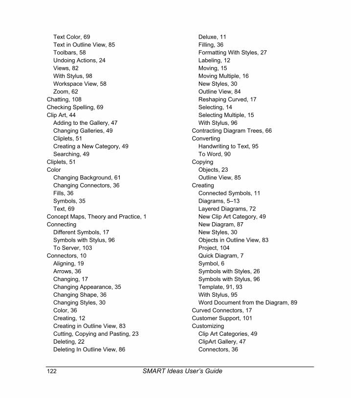
122 SMART Ideas User’s Guide
Text Color, 69Text in Outline View, 85Toolbars, 58Undoing Actions, 24Views, 82With Stylus, 98Workspace View, 58Zoom, 62
Chatting, 108Checking Spelling, 69Clip Art, 44
Adding to the Gallery, 47Changing Galleries, 49Cliplets, 51Creating a New Category, 49Searching, 49
Cliplets, 51Color
Changing Background, 61Changing Connectors, 36Fills, 36Symbols, 35Text, 69
Concept Maps, Theory and Practice, 1Connecting
Different Symbols, 17Symbols with Stylus, 96To Server, 103
Connectors, 10Aligning, 19Arrows, 36Changing, 17Changing Appearance, 35Changing Shape, 36Changing Styles, 30Color, 36Creating, 12Creating in Outline View, 83Cutting, Copying and Pasting, 23Deleting, 22Deleting In Outline View, 86
Deluxe, 11Filling, 36Formatting With Styles, 27Labeling, 12Moving, 15Moving Multiple, 16New Styles, 30Outline View, 84Reshaping Curved, 17Selecting, 14Selecting Multiple, 15With Stylus, 96
Contracting Diagram Trees, 66Converting
Handwriting to Text, 95To Word, 90
CopyingObjects, 23Outline View, 85
CreatingConnected Symbols, 11Diagrams, 5–13Layered Diagrams, 72New Clip Art Category, 49New Diagram, 87New Styles, 30Objects in Outline View, 83Project, 104Quick Diagram, 7Symbol, 6Symbols with Styles, 26Symbols with Stylus, 96Template, 91, 93With Stylus, 95Word Document from the Diagram, 89
Curved Connectors, 17Customer Support, 101Customizing
Clip Art Categories, 49ClipArt Gallery, 47Connectors, 36

SMART Ideas User’s Guide 123
Diagram, 34–53Diagrams, 25Symbols, 34
CuttingObjects, 23Outline View, 85
DDefault Styles, 31Defining
Cliplets, 51Concept Maps, 1Connector, 10Diagram, 2Diagram Trees, 65Fills, 36Global View, 55Notes, 38Outline View, 81Projects, 102Styles, 25Sub-Level, 54Symbol, 5Templates, 91
DeletingImages from Clip Art Gallery, 49In Outline View, 86Links, 80Objects, 22Project, 112Styles, 33
DiagramChanging, 34–53Changing Styles, 30Changing Trees, 66Comparing Views, 55Creating, 5–13Creating on Interactive Whiteboard, 95Creating with Stylus, 97Creating with Template, 87
Editing, 14–24Expanding Trees, 66Exporting, 90Exporting to Word, 89Layers and Links, 72Layout, 17Linking Levels, 76Management, 87New, 87New Styles, 30Opening, 88Organizing in Outline View, 85Printing, 91Rearranging, 15Saving, 88Styles, 25Trees, 65Trees, Collapsing, 66Viewing Sub-Levels, 64Views, 55
Disconnecting, 112Downloading, Project, 105Duplicating Objects, 23
With Styles, 25, 28
EEditing
Diagrams, 14–24Label Text, 67Note, 39Text in Outline View, 85With Stylus, 98
EffectsFills, 37Matte, 44Shadows, 41Transparent, 40
ExamplesCliplets, 51Comedy, 91
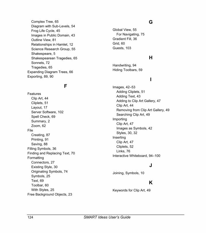
124 SMART Ideas User’s Guide
Complex Tree, 65Diagram with Sub-Levels, 54Frog Life Cycle, 45Images in Public Domain, 43Outline View, 81Relationships in Hamlet, 12Science Research Group, 55Shakespeare, 5Shakespearean Tragedies, 65Sonnets, 72Tragedies, 65
Expanding Diagram Trees, 66Exporting, 89, 90
FFeatures
Clip Art, 44Cliplets, 51Layout, 17Server Software, 102Spell Check, 69Summary, 2Zoom, 62
FileCreating, 87Printing, 91Saving, 88
Filling Symbols, 36Finding and Replacing Text, 70Formatting
Connectors, 27Existing Style, 30Originating Symbols, 74Symbols, 25Text, 69Toolbar, 60With Styles, 25
Free Background Objects, 23
GGlobal View, 55
For Navigating, 75Gradient Fill, 36Grid, 60Guests, 103
HHandwriting, 94Hiding Toolbars, 59
IImages, 42–53
Adding Cliplets, 51Adding Text, 43Adding to Clip Art Gallery, 47Clip Art, 44Removing from Clip Art Gallery, 49Searching Clip Art, 49
ImportingClip Art, 47Images as Symbols, 42Styles, 30, 32
InsertingClip Art, 47Cliplets, 52Links, 76
Interactive Whiteboard, 94–100
JJoining, Symbols, 10
KKeywords for Clip Art, 49

SMART Ideas User’s Guide 125
LLabeling
Changing with Stylus, 98Connector, 13Text Editing, 67
Layers, 72Layout, 7
Changing, 17With Quick Connect, 7
Lesson Material, 76Finding Images, 43
License Agreement, 113Lining Up, 19Linking, 10, 76
Removing, 80Sub-Levels, 79Symbols to Each Other, 10To a File, 78
Loading Styles, 32Locking Cliplets, 51
MMaking Diagrams, 5–13Managing Diagrams, 87Merging Projects, 106Moving
Connections, 17Diagram Objects, 15Objects, 23On Workspace, 63
NNavigating
Styles, 33Sub-Levels, 54, 72Symbol Layers, 75Watermarks and Sub-Levels, 64Workspace, 63
New
Connectors, 12Diagram, 7Labels, 12Symbols, 11
Notes, 22, 38, 68Adding in Outline View, 84
Notification of Visitors and Changes, 110
OObjects
Changing, 34–53Creating, 5–13Transparency, 40
Online Projects, 102–12Opening
Diagram, 88Project, 104Sub-Levels, 72Template, 92
OrganizingDiagram in Outline View, 85Outline View, 82
Outline View, 55, 81Changing Hierarchy, 85Changing Labels with Stylus, 99Creating Objects, 83Cutting, Copying and Pasting Symbols, 85Deleting Objects, 86Editing Objects with a Pen Tray Stylus, 99Editing Text, 85Exporting, 90Tools, 60
Owners, 103
PPage Layout, 18Panning on the Screen, 63Pasting
Objects, 23
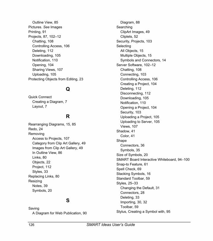
126 SMART Ideas User’s Guide
Outline View, 85Pictures. See ImagesPrinting, 91Projects, 87, 102–12
Chatting, 108Controlling Access, 106Deleting, 112Downloading, 105Notification, 110Opening, 104Sharing Views, 107Uploading, 105
Protecting Objects from Editing, 23
QQuick Connect
Creating a Diagram, 7Layout, 7
RRearranging Diagrams, 15, 85Redo, 24Removing
Access to Projects, 107Category from Clip Art Gallery, 49Images from Clip Art Gallery, 49In Outline View, 86Links, 80Objects, 22Project, 112Styles, 33
Replacing Links, 80Resizing
Notes, 39Symbols, 20
SSaving
A Diagram for Web Publication, 90
Diagram, 88Searching
ClipArt Images, 49Cliplets, 52
Security, Projects, 103Selecting
All Objects, 15Multiple Objects, 15Symbols and Connectors, 14
Server Software, 102–12Chatting, 108Connecting, 103Controlling Access, 106Creating a Project, 104Deleting, 112Disconnecting, 112Downloading, 105Notification, 110Opening a Project, 104Security, 103Uploading a Project, 105Uploading to Server, 105Views, 107
Shadow, 41Color, 41
ShapeConnectors, 36Symbols, 35
Size of Symbols, 20SMART Board Interactive Whiteboard, 94–100Snap-to Feature, 61Spell Check, 69Stacking Symbols, 16Standard Toolbar, 59Styles, 25–33
Changing the Default, 31Connectors, 28Deleting, 33Importing, 30, 32Toolbar, 59
Stylus, Creating a Symbol with, 95

SMART Ideas User’s Guide 127
Sub-Levels, 54Creating, 74Linking, 79Navigating, 74, 75Transparent Originating Symbols, 74Viewing Outlines, 63Watermarks, 64
SymbolColor, 35Shape, 35
SymbolsAdding Fills, 37Adding Text to Images, 43Adding to Sub-Level, 74Aligning, 19Changing Appearance, 34Changing Styles, 30Clip Art, 44Connecting, 12Connecting with Stylus, 96Creating, 6Creating Associated Sub-levels, 74Creating in Outline View, 83Creating New Connected, 11Creating with Stylus, 96Cutting, Copying and Pasting, 23Deleting, 22Deleting In Outline View, 86Filling, 34, 36Formatting with Styles, 25Importing Images, 42Importing Other Styles, 32Linking, 76Linking with Connectors, 10Moving, 15Moving Multiple, 16New Styles, 30Notes, 38Notes in Outline View, 84Outline, 34Resizing, 20
Resizing to Fit Text, 21Selecting, 14Selecting Multiple, 15Shadow, 41Stacking, 16Style List, 26Sub-Levels, 54Transparent, 40
TTemplates, 87, 91
Creating, 93Text, 67–71
Adding to Image, 43Changing in a Note, 39Changing in Outline View, 85Checking Spelling, 69Converting Handwriting, 95Exporting, 90Finding and Replacing, 70Formatting, 69In Connectors, 13In Notes, 38In Symbols, 6Injecting from SMART Board Interactive
Whiteboard, 94Injecting Labels, 97Outline View, 81Resizing Symbols, 21
Toolbar, 59Hiding, 59Outline View, 60Types, 59, 60
Transparent, 40Originating Symbols, 74
Trees, 65Two-Color Pattern Fills, 36

128 SMART Ideas User’s Guide
UUndoing Changes, 24Uploading, to Server, 105Users, 103
VViews, 55
Changing, 58, 82Changing Diagram Trees, 66Diagram Trees, 66Exporting, 90Global, 55Outline, 81Panning, 63Projects, 102Show Sub-Levels, 74Sub-Levels, 63
Toolbars, 58Watermarks, 64Zoom, 62
WWatermarks, 64Web
Exporting, 90Links, 77
Word Document, 89Workspace, 54
Navigating, 63Writing, 94
ZZoom, 62

�� Encourage creative thinking in your classroom
�� Enhance lessons using interactive concept maps and multimedia
�� Engage students with visual learning techniques
Ideas are exciting! Energize your classroom and captivate students with
this creative, visual learning tool from the makers of the SMART BoardTM
interactive whiteboard.
SMART Ideas concept-mapping software gives students the power to
brainstorm, turn abstract ideas into easily understood visual maps and
organize thoughts and images into roadmaps for learning.
Use colorful shapes, cool connectors and a collection of curriculum-
specific clip art to enhance your lessons and engage students. Create
multilevel concept maps and delve into the details. Then add multimedia
to your maps by making documents, videos and Web sites accessible
with a single mouse click.
Whether the topic is simple or complex, SMART Ideas software helps
you show students what you mean.
Concept-Mapping Software
© 2003 SMART Technologies Inc. All rights reserved. SMART Ideas is a registered trademark of SMART Technologies Inc. in Canada and the U.S. SMARTIdeas, SMART Board, the SMART Ideas logotype and the SMART logo are trademarks of SMART Technologies Inc. Printed in Canada 11/2003
Suite 600, 1177 – 11th Avenue SWCalgary, AB CANADA T2R 1K9Toll free 1.888.42.SMART Tel. 403.245.0333 Fax [email protected] www.smartideas.com
57-00481-00