Smart Home App
82
Smart Home App Commissioning and Operating Instructions
Transcript of Smart Home App
Smart Home App
Commissioning andOperating Instructions

Revision 2.0 english, Edition 05/2021Smart Home App, commissioning and operating instructions © 2021 ubisys technologies GmbH, Düsseldorf.All rights reserved. Reproduction and copies (also in extracts) only with the consent of ubisys technologies GmbH.
This document may contain errors in content. However, it will be revised regularly and corrected accordingly in the next edition. We accept no liability for errors in content.Changes in the sense of technical progress can be made without prior notice.

3Smart Home App
Contents
Contents
Chapter 1 | Important Safety Notifi-cation
Chapter 2 | General Information
2.1 Notes on this manual2.2 System information on ubisys Smart Home and the ubisys Smart Home App2.3 Features2.4 Security and data protection2.5 Availability
Chapter 3 | Commissioning
3.1 Setting up the Smart Home System3.2 Finding Smart Home Systems in the local network3.3 Adding Smart Home systems manually3.4 Connecting your smartphone/tablet to your Smart Home System for the first time
Chapter 4 | Configuration
4.1 First steps for configuring your Smart Home system via app4.1.1 Edit rooms (create, name or delete)4.1.2 Open for new devices4.1.3 Components (edit names, delete, functions, search)4.1.4 Assigning components to rooms or deleting them again4.2 Additional functions for configuring your Smart Home System4.2.1 Bindings4.2.2 Groups4.2.3 Scenes4.2.4 Scheduled actions4.2.5 Configuring the J1(-R) shutter controller
Chapter 5 | Building Control
5.1 Displaying the switched on units5.2 Light control5.3 Switchable socket5.4 Shutter and skylight control5.5 Update states
Chapter 6 | Scenes
Chapter 7 | Alarm System
7.1 Arming/disarming the alarm system7.2 Individual configuration of the alarm functions
Chapter 8 | Automations
8.1 Automations8.2 Explaining the configuration options 8.3 Using an automation8.4 Description of the graphs for sample automations8.5 Automation samples
Chapter 9 | Settings
9.1 Facilities
Chapter 10 | Additional Functions and Notes
10.1 Updates10.2 Contact
4
6
7
7889
10
11
12
15
17
20
212123
24
28
303031343947
50
5152535354
55
57
59
62
64
657375
7677
79
80
81
8282
4Smart Home App
Chapter 1Important Safety Notification

5Smart Home App
Chapter 1 | Important Safety Notification
Caution: Do not switch on any dangerous loads via the app if you are not in the vicinity or if you do not have a reliable overview of the situation on site, e.g. via a camera and sensors. If, for example, you are not sure whether you have switched off your hot iron, it is absolutely sensible to switch off the socket in question, even and especially if you are not on site.
However, you should never switch on sockets remotely if you are not absolutely sure that no dan-gerous loads are connected at that time.
Dangerous consumers are primarily all devices that must not be operated unsupervised, e.g. because they can generate significant heat or exert mechanical forces. In other words, all consumers and devices that have the potential to cause damage to persons, animals or parts of buildings. Fire hazards are posed, for example, by irons, hotplates, coffee machines, kitchen appliances, sauna ovens, high-power halogen radiators, etc., risk of bruising and contusions from automatic doors, windows, shutters, etc. damage due to overflow of liquids from pumps etc.

6Smart Home App
Chapter 2General Information

7Smart Home App
Chapter 2 | General Information
2.1 Notes on this manual
Read this manual carefully before you start using your ubisys Smart Home App. Keep the instructions for future reference. You can find an electronic version at www.ubisys.de.
Who is this document aimed at?This document is intended for persons who:
• carry out the commissioning of the ubisys Smart Home App• use the ubisys Smart Home App to configure, monitor or operate a ubisys Smart Home System.
IllustrationsThe illustrations in this manual correspond to the screens of the Apple iOS app on an iPhone 10 withiOS 14.2.With the app for Apple iPad, on a newer iOS version or on devices with Google Android operating system, slight deviations - in terms of display or operation - are possible.
2.2 System information on ubisys Smart Home and the ubisys Smart Home App
This component is part of ubisys Smart Home. To be able to use the app, you need additional components.All devices are usually delivered with a standard configuration.
All documents for the commissioning of your Smart Home System are always available in electronic form at www.ubisys.de.
What are the requirements for using the ubisys Smart Home System or the app?In order to be able to use the ubisys Smart Home System or the App, the following requirements must be met:
• Gateway G1 must be properly connected (check instructions).• At least one Zigbee standard conform component, e.g. universal dimmer D1, shutter control J1, power
switch S1, etc. must be properly installed• ubisys Smart Home App must be properly installed on a smartphone or tablet with an iOS or Android ope-
rating system.
8Smart Home App
Chapter 2 | General Information
2.3 Features
Smart Home App for smartphones and tabletsUsing the ubisys Smart Home App allows you to control your property via iPhone, iPad or iPod touch - on the go or from any room in your house or apartment. Also available is a version for smartphones or tablets with Google Android operating system. Via mobile communications or WiFi you can keep an eye on your building technology at all times. Via the intuitive user interface, the following functions, among others, are available:
• Building control (lighting, blind and shutter control, switching of sockets, etc.): The scope is constantly being expanded, e.g. to include heating regulation, etc.
• Scenes: Activate predefined settings for dimmers, blinds and other devices at a push of a button• Settings: Name rooms, add new components, or link existing control elements to any consumers, e.g. a wall
switch with a group of lights.• Alarm system: Monitor your property even when you‘re on the move and receive alarm messages in form of
push notifications• Automations: Use automation templates, e.g. for automatic lighting control• Power consumption display• Switch between multiple properties• Free software updates
2.4 Security and data protection
Your security and the security of your real estate are a top priority for ubisys. That is why our development de-partment has attached great importance to encryption and authentication procedures from the very beginning, which guarantee that only you have access to the components of the system at any time. In addition, you as a system operator must also take basic security concepts to heart in order not to compromise the security of the system.
2.4.1 Security of the radio connectionsAttacks via the radio interface require an attacker to be within radio range of your system. These attacks are therefore not the primary target of common hackers, who are more likely to focus on globally accessible com-ponents such as gateways. Nevertheless, we have attached great importance to the fact that the radio interface also meets the highest security requirements. As the operator of a public facility, e.g. a hotel, a holiday resort, a company or a public authority with public traffic, the danger of an attack via a radio interface must be taken seriously. The radio connections between individual components of the ubisys Smart Home System are based on the stan-dard Zigbee Home Automation, which in turn is based on the core technology Zigbee. Zigbee includes security functions, such as an AES-128 network key, to make data unreadable to third parties who might be within radio range of your system. In addition, it is not possible for attackers to inject control commands into your network, or to record legitimate control commands for later replay („replay attack“).

9Smart Home App
Chapter 2 | General Information
2.4.2 Security of the gatewayThe gateway hosts various services that are necessary for the accessibility of your system from the outside or certain time- or event-controlled processes. These include in particular the Smart Facility Service, which establishes the connection between the system and the Smart Home App on the various mobile end devices. By its very nature, this service must be accessible from the outside. Therefore, all connections from apps to this service are specially secured and encrypted. When a system is set up in the app, an access authorisation is installed on the smartphone with which access to the system is later possible. You can lock a lost smartphone out of the system at any time via the gateway‘s the web interface. You should not make the web interface of the gateway available to the outside, therefore do not set up port forwarding for TCP port 80. for TCP port 80, but only use local access or a secure connection, e.g. via VPN, to access the web interface.
2.4.2.1 Remote MaintenanceRemote maintenance is carried out via a secure connection, which is protected by a certificate and explicitly released via the web interface of the gateway. An ongoing remote access is displayed in the user interface. As a result nobody except the ubisys support team has possibility of accessing your system – and even then only if you explicitly permit the access.
2.4.3. Cloud servicesCurrently ubisys Smart Home does not use any cloud services and does not store any data of your system or create any usage profiles. Therefore, there is no risk to the protection of your data in this respect.
2.5 Availability
Apple (iOS 11 or higher):• iPhone (5S or newer models)• iPad Mini 2 (or newer models)• iPad (5th generation or newer models)• iPad (Pro 9,7” or newer models)• iPad Air (or newer models)• iPod touch (6th generation or newer models)
Google Android (Version 5 or higher), e.g.:• Samsung Galaxy• Samsung Galaxy Tab• Huawei

10Smart Home App
Chapter 3Commissioning

11Smart Home App
Chapter 3 | Commissioning
3.1 Setting up the Smart Home system
Note: For a quick and easy setup of your Smart Home system, we recommend the ubisys„Smart Home – Quickstart“. You can find this step-by-step guide in the download area of our website.
1. Connect the Smart Home Gateway G1 to your home network (I)2. Connect the supplied power supply unit. The LED (A) on the front panel should now flash and start your
gateway.
Gateway G1
A
K
B C D E
F
G H
J
I
ABC
DEFGHI
JK
Status LEDAntenna connector (optional)USB 2.0 connection (currently BLE use only)EthernetPower socketReset buttonNetwork cablePower supplyYour DSL, UMTS or LTE routerOutlet External antenna (optional)
3. Download ubisys Smart Home app (app Store QR-Codes to scan)

12Smart Home App
Chapter 3 | Commissioning
4. Follow the instructions on your end device. 5. The app automatically guides you through the activation of your
operating device. To access to your system, simply scan the bar-code on the back of your gateway. To do this, select Enter code.
6. From now on you can automatically access your system from the local network as well as on the go, provided that your smartphone or tablet has an active network connection. If rooms have been created, and the installed components and rooms have already been named (usually done by the installer), your ubisys smart home system is immediately ready for use. Control and monitor your building technology easily and intuitively and create scenes or time-controlled events. You can find all infor-mation on this in the manual for the smart home app in the down-load area of the ubisys website.
Note: In case no rooms have been created, and the installed com-ponents haven´t been named and assigned to rooms yet, continue with chapter „Configuration“.
Note: If the setup via the QR code does not work (e.g. the code is damaged or missing), enter the serial number (S/N) and the setup code (I/C) of the gateway in the app.This also ensures that you can access your system from the local network and when you are on the go.
3.2 Finding Smart Home systems in the local network
System requirementsFor commissioning, you should have a direct connection to the local network in which the gateway is located. For example, if the gateway is connected to your DSL router, then your smartphone or tablet should also be logged into the same network via WiFi. This makes the search function available to you with which you can find the gateway in the network without knowing its Internet address. The gateway identifies itself in the network via Apple Bonjour (mDNS).

13Smart Home App
Chapter 3 | Commissioning
Note: It is also possible to put a facility into operation without the smartphone or tablet being logged into the the same network as the gateway. In this case, however, the Internet address and, if applicable, theport of the system must be known and entered manually.
Make sure that the requirements described above are met, in particular, WLAN must be activated on the smartphone which must be logged into the same local network to which the gateway is connected. You canthen search for gateways as follows:
1. Drag the list downwards until the gateway discovery begins. New gateways appear in the list. For already known gateways for which no local address was known so far, the address information is added instead.
2. A list with the discovered gateways appears.

14Smart Home App
Chapter 3 | Commissioning
3. Tap on a system to establish the connection.
4. A connection is established.
Note: If a connection is not established, there probably is a configuration problem at the network level. This can happen, for example, if the smartphone and gateway are located in different subnets, which can be caused by an incorrect manual network setting or several DHCP servers with different settings in the local network. If so, please check the network configuration as descri-bed in point 5:
5. Tap on Settings -> Wi-Fi on your home screen.
6. Tap on the active network (with a checkmark, framed red).

15Smart Home App
Chapter 3 | Commissioning
7. In a network with subnet mask 255.255.255.0, make sure that the first three groups of digits (marked red in this example = 192.168.0.) of the IP address of your smartphone correspond with those of the IP address of the gateway. The IP address of the gateway can be seen in the list of gateways (see e.g. illustration under point 3) below the designation in brackets behind the serial number. If the address is not completely visible swivel the smart-phone to landscape format. For the subnet mask 255.255.0.0, compare the first two groups of digits. For the subnet mask 255.0.0.0 compare the first group of digits. For other subnet masks contact your network administrator. If the above groups of digits differ, several DHCP servers may be active in the network or the manual configuration of the network address of the gateway is faulty.
Note: Please be aware that with this procedure you cannot access your system from the road, but only from the local network.
3.3 Adding Smart Home systems manually
Sometimes it is necessary to add a system manually, for example if external access is to be set up or the gate-way and smartphone or tablet are not in the same local network.
1. Start the app.
2. Tap on the pencil icon in Settings -> Facilities. If you are on the start screen, touch the screen for two seconds.

16Smart Home App
Chapter 3 | Commissioning
3. The view changes to the configuration view.
4. Scroll down and tap on „New Facility“.
5. Enter the public IP address of your router or the host name in the input field, and if necessary, a port. The host name can also be a DynDNS address. Confirm by tapping on „OK“.
6. The newly entered gateway now appears in the list of available gateways. Tap on the list for one second (or tap on the checkmark, if the pencil symbol was used), to exit edit mode.
7. Swipe down to update the list of available gateways in the network. If an external (internet) address is already known for a gateway, the entry is the entry is supplemented by the internal (WLAN) address. Your Smart Home System can then be reached via WLAN on site as well as via UMTS when you are on the go. Please also pay attention to the note below!
8. As of now your Smart Home system can also be reached via your app while on the go.

17Smart Home App
Chapter 3 | Commissioning
Attention: Not all routers can establish a connection via the public address internally, for instance when your smartphone is in its own WLAN. Such as the Fritzbox from AVM and Speedport from Telekom. Others, ho-wever, such as the easybox from Vodafone, are able to.
If your router does not provide this functionality, proceed as follows:
1. Temporarily disable the WLAN function on your smartphone.2. Tap on the gateway in your app and wait until the connection is established. If the gateway was already
entered in the app, the second entry disappears. Instead, an entry with more than one address remains. If not, an access code is necessary.
3. Switch the WLAN in the smartphone on again. From now on, the app automatically establishes the connec-tion to the gateway via one of the two addresses. It won´t be necessary to switch off the WLAN function of your smartphone anymore.
3.4 Connecting your smartphone/tablet to your Smart Home system for the first time
Note: This procedure should be followed if the setup has not been done using the QR code or the serial number and setup code.
1. Tap on the app icon to start the app.

18Smart Home App
Chapter 3 | Commissioning
2. A list appears with the facilities that have already been added.
3. Tap on the facility (gateway) that you want to control.
4. You will be asked for an enrollment code to authorise your device.
5. Open the user interface of the gateway in a web browser (more on this in the corresponding instructions for the gateway G1).
6. Click on „Security“ in the main navigation.
7. In the section „Enable access for an additional device“ you can generate or activate an access code (see illustration below).
Note: For security reasons, the activated access code is only valid for approx. 5 minutes. If you do not enter the code on your opera-ting device (e.g. smartphone) during this time, the code becomes invalid and you must generate/activate a new one.
8. Enter your access code.

19Smart Home App
Chapter 3 | Commissioning
9. Your smartphone/tablet establishes a connection to your gateway at the corresponding property.
You are now on the start screen of the user interface.
Note: When you first connect, most of the items are greyed out and inactive as no configurations have been made yet.

20Smart Home App
Chapter 4Configuration

21Smart Home App
Chapter 4 | Configuration
Note: It is possible to begin commissioning the Zigbee components without a gateway and app, for example if the property is still in its shell construction phase and the gateway cannot be set up and connected to a net-work. In such a case you can use the ubisys Network Manager software on a windows PC with the ubisys Zig-bee USB Stick U1, you can set up the components beforehand, test them and, for example, create important bindings. The instructions in this chapter, however, refer to setting up the system via app and gateway.
4.1 First steps for configuring your Smart Home system via App
In order to be able to control your Smart Home system via the app, you first have to configure it (for instance naming, assigning components to rooms, etc.). This can be done directly via the ubisys smart home app. The configuration is saved on the gateway as well as partly on the individual components. When you register additio-nal operating devices, the current configuration will automatically be available on the newly added device.
The steps described below also refer to settings that are made after the initial configuration. For instance if you have added components and want to integrate them into your system.
Changes to the system configuration can only be made from one device at a time. It does not matter which of the units you are using. For the period of editing, only the respective unit has exclusive access to the system. You can, of course, still use all the other devices simultaneously for controlling the smart home system. As soon as the changes are made, the menu on all other units will automatically be updated.
To configure your system via the app, proceed as follows:
4.1.1 Edit rooms (create, name or delete)To be able to find the rooms in the building control equipped with ubisys components, you must first create and name them first. Proceed as follows:
1. Tap on: Configuration -> Basic Configuration -> Rooms.
2. Tap on the pencil symbol at the upper right corner to edit „Rooms“.

22Smart Home App
Chapter 4 | Configuration
3. Tap on „New room“ to create a room. Tap on the minus sign („-“) to delete the corresponding room. To change the order, hold your finger on the (3 crossbars) and drag the room to the desired position. This way you can move frequently used rooms to the top. Tap on the cross to the upper left to cancel the process and all changes will be discarded.
4. To change the name of a room, tap on it and enter a name for the room.
5. Tap the star symbol to select an icon for the room you have crea-ted.
6. Select an icon for the room you have created. The current symbol is highlighted in light grey.

23Smart Home App
Chapter 4 | Configuration
7. Tap on the checkmark to save your settings.
4.1.2 Open for new devicesIn order for the devices installed in your property to be displayed in your app, they must first be „added“ to the system with the help of the app. To do this, proceed as follows:
1. Tap on: Configuration -> Basic Configuration.
2. Tap on „Open for new devices“.
3. The Zigbee wireless network is now open for new devices for about two minutes before it is automatically closed again. To close the network again earlier tap on „Close again“.
Note: Depending on the settings on your gateway, during this time window new Zigbee components receive the current network key without verification, which secures communication in the Zigbee network. Only with devices that are added to the network by means of an installation code, the key transport in itself is also encrypted.
4. The number of included devices is indicated with a blue back-ground in the field „Components” as long as you have not yet configured the device.

24Smart Home App
Chapter 4 | Configuration
4.1.3 Components (edit names, delete, functions, search)During the initial configuration, various settings of your ubisys Smart Home components can be changed. First you should name each component as this name identifies the entire component, in case of the power switch S2 the module itself, and ultimately helps with the remaining setup. This way you do not need to remember the serial numbers of the devices. This designation will not be displayed in the building control menu but only serves as a configuration aid. A common form of designation, for example, would be „S2, ceiling light, hallway“.
Each component has functions, for example, outputs to which consumers can be connected, or inputs that can be connected to switches, push-buttons, motion detectors, etc. but also measuring capabilities for power consumption and metering capabilities for energy consumption or even renewable energy fed back into the grid. With Zigbee devices, these individual functions are addressed via so-called endpoints. More than 250 endpoints can be distinguished per device. The endpoint addresses in the app are displayed with a preceding hashtag (#), the international symbol for „number“. The functions that correspond to the end points can also be named. These names are then displayed in the building control menu, within the rooms you will later have to create. Select names without a room designation, for example, „Ceiling light“ for an output, or „Wall switch“ for an input. The power switch S2, for example, has two load outputs (red and black connecting leads) and two control units for switching commands, sending commands via the Zigbee network turning load switches on or off. It also includes an energy consumption meter. The inputs of the module (white and grey connecting leads) can be as-signed to the various available control units of a module. Depending on the model, the control units available are for switching and dimming, for driving roller shutters, awnings, venetian blinds and screens as well as for calling up scenes.
Edit or delete names
1. Tap on: Configuration -> Basic Configuration.
Note: The number with a blue background indicates the number of components that have not yet been configured.

25Smart Home App
Chapter 4 | Configuration
2. Tap on the pencil icon on the upper right to edit the name or delete a component.
Note: The blue background „new“ indicates a component that has not yet configured. A component is considered to be configured when it has been given a name, or one of its functional units has been given a name or has been assigned to a room.
3. Tap on the component whose name you want to edit. To delete a component, tap on the corresponding ( – ). Tap on the checkmark on the upper right to save the settings. Tap on the cross to the upper left, to cancel the process.
Note: The name is only used for orientation in the configuration section and is synonymous with the serial number.
Naming the functions of a component
1. Tap on the component.

26Smart Home App
Chapter 4 | Configuration
The relevant functional units of the module are displayed here. These include switchable and dimmable components, shutter motor output stages and the corresponding control units. The Zigbee endpoint addresses are displayed below the name of the functional unit, as well as the room to which the unit be-longs. For units whose physical inputs can be flexibly assigned to control units (on/off or dimmer switch, shutter control, scene switch), the menu item „Input configuration“ is also displayed, via which you can change this assignment, or determine whether a switch or push-button is connected.
2. In order to edit the names of the functional units tap on the pencil symbol to the upper right.
Note: Within the building control menu the name will be displayed below a room.
3. Tap on the functional unit you want to edit and enter a name.
4. Tap on the checkmark on the upper right to save your settings. Tap on the cross to the upper left, to cancel the process.
Assigning inputs to a functional unit
Most ubisys Zigbee devices allow you to assign different functions and behavi-ours to the inputs that are optimally adapted to the installed devices. For exam-ple, you can use a double push button to dim a single luminaire, or use a single push-button to dim, but also use a switch or the output of a motion detector for switching on or off. For units that house different control units for example a dimmer control, a shutter control and a scene switch, it is possible to assign these functions accordingly.
1. Tap on „Input Configuration“.

27Smart Home App
Chapter 4 | Configuration
2. For editing the operating mode (assign a function) tap on the pen-cil icon to the upper right.
3. For deleting a mode tap on the corresponding ( - ).
4. For adding a function tap on „Add function“. You then have the option of assigning suitable functions.
5. For saving your settings tap on the checkmark in the upper right corner. To cancel the process, tap on the cross in the upper left corner.
Please keep in mind that the devices are usually fully assigned when delivered, therefore the inputs already have a certain function. If you try to add more functions to an input you will receive an error message, as shown here. In this case you must first delete one or more function assignments so that inputs become free, which you then can assign differently.

28Smart Home App
Chapter 4 | Configuration
Search for components
If you have installed components but they are not displayed in the list, proceed as follows:
1. Swipe down the list of components to refresh the display.
Note: In the Android version there is a separate menu item „Net-work discovery“ available for this purpose.
4.1.4 Assigning components to rooms or deleting them againIn order for your system to know where the installed components are located in your property, you first have to assign them to the corresponding rooms. This is done via „Rooms“, for example you select a room you have created (check „Edit rooms (create, name or delete)“) and assign the components installed there to it. Proceed as follows:
1. Tap on: Configuration -> Basic Configuration -> Rooms.
2. Tap on the room to which you want to assign components to.
Note: If you haven´t created a room yet the list will initially be empty.

29Smart Home App
Chapter 4 | Configuration
3. Tap on the pencil icon to the upper right to assign components to the room or to delete components.
4. Tap on „Add device“ in order to assign components to the room. Tap on ( – ) to delete the corresponding component. To change the order tap, hold then drag the component to its desired position. To cancel the process, tap on the cross to the upper left.
5. Tap on the components that are located in this room.
6. Tap on the checkmark to the upper right to save the setting. To cancel the process, tap on the cross to the upper left.

30Smart Home App
Chapter 4 | Configuration
4.2 Additional Functions for Configuring your Smart Home System
4.2.1 BindingsZigbee components allow flexible assignment of control units (for example, wall push-button as dimmer control, shutter double push-button as shutter control) to consumers (for example luminaire at the output of a dimmer, socket at the output of a power switch) etc. This flexible assignment is called „binding“. Bindings are stored on the device, which in the context of this manual is generally referred to as the control unit. The control unit sends commands to the target device, to turn it on or off, set the brightness, or recall a scene. In general, possible targets for bindings are control units on devices that are clearly defined by the serial number of the device and the endpoint address, or groups. It is possible to assign several targets to a control unit, for instance several individual functional units of one or different devices or one group and one device.
These bindings function independently of the gateway or the app. The control commands are exchanged directly exchanged between the devices involved.
All ubisys devices are delivered with partially pre-configured bindings. For example, the input of an S1 is confi-gured to switch its own output. These bindings can be cancelled at any time or created again.
To create or cancel a binding, proceed as follows:
Create/cancel bindings
1. Tap on: Configuration -> Bindings. Here you see a list of all functional units allowing external bindings as well as themselves being the source of a binding. Generally, these are control units that are connected to operating elements such as switches or push-buttons.
2. Tap on the functional unit you want to edit.
Here you see a list of the destinations, functional units and/or groups, of the previously selected source functional unit (control unit).
3. Tap on the pencil icon to the upper right to create a link or edit the existing ones.

31Smart Home App
Chapter 4 | Configuration
4. Tap on „New Binding“. For deleting the existing shortcut, tap on ( – ). To cancel the process, tap on the cross to the upper left.
Here you see a list of available destinations for the binding. These are gene-rally all groups and compatible functional units on the devices installed in the system.
5. Tap on the desired components or groups that are to be the target of the binding. To cancel the process, tap on the cross to the upper left.
6. Tap on the checkmark to the upper right to save the setting.
4.2.2 GroupsIn order to design a scene, you first have to create a group (check section „Configuration“, “Scenes“). All components you want to be activated in your scene first must be included into a group. You can also include a component into several groups in order, for example, to define different settings for this component in different scenes.

32Smart Home App
Chapter 4 | Configuration
Being part of a group is stored in the individual Zigbee components. This way groups can be ddressed even if the gateway is switched off.
To create or edit a group, proceed as follows:
Creating a new group
1. Tap on Configuration -> Groups.
2. Tap on the pencil icon to the upper right to create a new group.
3. Tap on „New Group“. To cancel the process, tap on the cross to the upper left.
4. Select the components you want to group (highlighted in light grey). To cancel the process, tap on the cross to the upper left.

33Smart Home App
Chapter 4 | Configuration
5. Enter a name for the group.
6. Tap on the checkmark to the upper right to save your settings. To cancel the process, tap on the cross to the upper left.
7. Your settings have been saved.
Editing an existing groupFor editing the name only:
1. Tap on the pencil icon and enter a new name. To edit the group (delete or add components):
1. Tap on the group.

34Smart Home App
Chapter 4 | Configuration
2. For removing a component from the group, tap on the correspondi-ng ( – ). For adding a component, tap on „Add device“. To cancel the process, tap on the cross to the upper left.
3. When you have tapped on „Add device“, select the desired com-ponents. Tap on the checkmark to the upper right to save your settings. To cancel the process, tap on the cross to the upper left.
Deleting an existing group
1. When in the group menu, tap on the pencil icon in the upper right corner.
2. Tap on ( – ) of the group you want to delete. To cancel the process, tap on the cross to the upper left.
4.2.3 ScenesIn „Scenes“ you can define and change settings for dimmers, blinds and other devices and delete them at any time. As an example: When the created scene is activated, all blinds go down and the light comes on at the same time.

35Smart Home App
Chapter 4 | Configuration
Note: All components that you want to include in a scene must first be grouped together in a „Group“. You can find out how to create a group in the „Groups“ section.
Scenes are stored in a distributed manner. Each of the Zigbee components that belongs to the respective group stores its own settings, for instance, a dimmer its brightness level, a coloured light its colour, a power switch its switching status, etc. Therefore, a scene can also be called up by means of a scene selector switch without having to go through the gateway.
To create or edit a scene, proceed as follows:
Creating a new scene
1. Tap on Configuration -> Scenes.2. Tap on the pencil icon to the upper right to create a new scene.
3. Tap on „New Scene“. To cancel the process, tap on the cross to the upper left.
4. Select the intended group that you have designated for the scene. To cancel the process, tap on the cross to the upper left.

36Smart Home App
Chapter 4 | Configuration
5. Enter a name for the scene.
6. Tap on the checkmark to the upper right to save your settings. To cancel the process, tap on the cross to the upper left.
7. A list with the existing scenes appears.
8. Tap on the newly created scene.
9. You now will see the list with the components of the selected group that you have intended for the scene (red: settings to be made).
10. Tap on the pencil icon to the upper right to make the settings for the components (e.g. Switching on/off, dimming to any brightness level, etc.).

37Smart Home App
Chapter 4 | Configuration
11. Now set the individual components in a way that corresponds to the intended state when the scene is later called up. Use the App or the control elements of the components, such as wall switches, push-buttons, etc., to do this
12. When you have made your settings tap on the checkmark to the upper right to save them. To cancel the process, tap on the cross to the upper left.
13. As soon as the scene has been saved, the scene overview is dis-played.
Note: You can now call up the scene via the „Scenes“ menu in the main menu. The components automatically take on their pre-set values.
Editing an existing scene To edit the name:
1. Tap on the pencil icon to the upper right in the scene menu.
2. Tap on the scene to be edited (check illustration).
3. Enter a new name.
4. Tap on the checkmark to the upper right to save your settings. To cancel the process, tap on the cross at the top left.

38Smart Home App
Chapter 4 | Configuration
For editing the scene (change component settings):
1. Tap on the scene you want to edit.
2. Tap on the pencil icon in the upper right corner to edit your set-tings.
3. Select your settings via the app or the control units (switches/but-tons).
4. Tap on the checkmark to the upper right to save your settings. To cancel the process, tap on the cross to the upper left.

39Smart Home App
Chapter 4 | Configuration
5. Your settings are saved.
Deleting an existing scene
1. When in the scenes menu, tap on the pencil icon to the upper right.
2. Tap on ( – ) of the scene to be deleted (check illustration). Tap on the checkmark to the upper right to save your settings. To cancel the process, tap on the cross to the upper left
4.2.4 Scheduled actions
Note: To configure the time function, you need the iOS app version 1.2 or higher.
Via „Scheduled Actions“ you have the option of creating various types of time-controlled events. This function is very suitable, for example, for presence simulations or to automate recurring events. Additional functions: Astronomical clock, random times, different time schedules for different weekdays and public holidays, and much more.
Examples:During the week, if not a public holiday, raise the blinds in the whole house at sunrise (but not before 06:45 hrs.), in the bedroom however leave them down and only set the slats to 45°. At the weekend and on public holidays, this should happen no earlier than 09:00.
During your vacation, switch on and dim the light in different rooms, randomly between half an hour before and one hour after sunset. Between 22:30 and 23:45 then one after the other switch off the lights, with the bedroom being the last.
The time schedule is not based on a cloud service and therefore works regardless of whether an internet con-nection is available or, for example, has temporarily failed.

40Smart Home App
Chapter 4 | Configuration
Attention: For using the time functions you need the gateway firmware version 1.0.35 or higher. For location-based services such as the astronomical clock, enter the location of the system via the web interface of the gateway. That is where you can also select the fitting holiday calendar according to your location.
Note: In order to create a scheduled action, you first have to specify the intended states of the components involved (dimmers, blinds, etc.) in a „scene“. How to create a scene, you´ll find in the „Scenes“ section.
There are various types of time functions available for different tasks, which then can be combined an unlimited number of times. Configuration and activation/deactivation is done as follows:
Trigger action at a time of day (daily at a certain time)Select a time of day and optionally specify days of the week. You can include or exclude public holidays, specify a time span for random execution (for example, half an hour earlier up to a quarter of an hour later than scheduled), as well as restrict the validity period by defining the first and last execution.

41Smart Home App
Chapter 4 | Configuration
1. Tap on: Configuration -> Scheduled Actions.
2. Tap on the pencil icon in the upper right corner to create or delete a scheduled action.

42Smart Home App
Chapter 4 | Configuration
3. Tap on „New schedule“. To delete a schedule, tap on the corresponding ( – ). Tap on the checkmark to the upper right to save your settings. To cancel the process, tap on the cross to the upper left.
4. Tap on „at a time of the day“.
5. Specify a time of the day at which the action is to be carried out.
6. Tap on „Actions“ and then on the next page on „New action“ to select the intended scene.
Note: You can also select multiple scenes. Simply expand your list by tapping on „New action“ again.
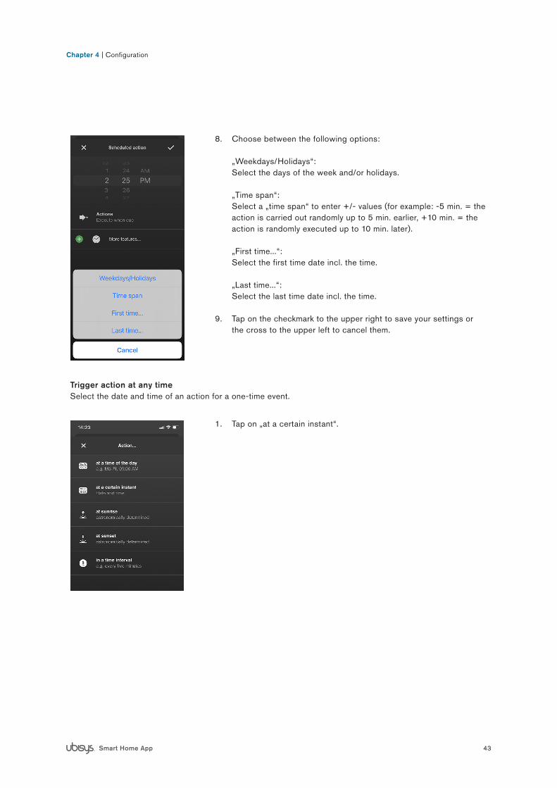
7. Tap on „More features...“ to set days etc.
43Smart Home App
Chapter 4 | Configuration
8. Choose between the following options: „Weekdays/Holidays“: Select the days of the week and/or holidays. „Time span“: Select a „time span“ to enter +/- values (for example: -5 min. = the action is carried out randomly up to 5 min. earlier, +10 min. = the action is randomly executed up to 10 min. later). „First time...“: Select the first time date incl. the time. „Last time...“: Select the last time date incl. the time.
9. Tap on the checkmark to the upper right to save your settings or the cross to the upper left to cancel them.
Trigger action at any time Select the date and time of an action for a one-time event.
1. Tap on „at a certain instant“.

44Smart Home App
Chapter 4 | Configuration
2. Set the date and time at which the scheduled action is to be car-ried out.
3. Tap on „Actions“ and then on the next page on „New action“ to select the intended scene.
Note: You can also select multiple scenes. Simply expand your list by tapping on „New Action“ one more time.
4. Tap on the checkmark to the upper right to save your settings or the cross to the upper left to cancel them.
Trigger an action at sunrise and sunsetDepending on the location of your system, the astronomically determined times for the sunrise and sunset are calculated and can be used as the basis for time controls. In addition, time offsets (earlier than planned, later than planned) and a time span for random execution can be specified. Furthermore, times of day can be specified as a limit, for example not before 07:00h, not after 22:00h. Variations can also be set up for different days of the week, as well as public holidays which can be included or excluded.
1. Tap on „at sunrise“ or „at sunset“.
2. Tap on „Actions“ then on the next page on „New action“ to select the intended scene.
Note: You can also select multiple scenes. Simply expand your list by tapping on „New Action“ one more time.
3. Tap on „More features...“ to set days etc.

45Smart Home App
Chapter 4 | Configuration
4. Wählen Sie zwischen folgenden Optionen: „Weekdays/Holidays“: Select the weekdays and/or holidays. „Not before... (time of day)“/“Not after... (time of day)“: Select a corresponding time of day. „Time shift“: Select an offset time (for example one hour before sunrise, or 45 minutes after sunrise). „Time span“: Select a „time span“ to enter +/- values (for example: -5 min. = the action is carried out randomly up to 5 min. earlier, +10 min. = the action is randomly executed up to 10 min. later). „First time...“: Select the first-time date incl. the time. „Last time...“: Select the last time date incl. the time
5. Tap on the checkmark to the upper right to save your settings or the cross to the upper left to cancel them.
Trigger an action at a regular intervalHave an action performed at regular intervals, for instance every minute, every hour, every eight hours etc. Also supports variations for different days of the week, holidays, random periods and absolute limits for times of day (for example not before 10:00h, not after 14:00h).
1. Tap on „in a time interval“.

46Smart Home App
Chapter 4 | Configuration
2. Tap on „Actions“ and then on the next page on „New action“ to select the intended scene.
Note: You can also select multiple scenes. Simply expand your list by tapping on „New Action“ one more time.
3. Tap on „More features...“ to specify days etc.
4. Choose between the following options: „Weekdays/Holidays“: Select the weekdays and/or holidays. „Not before... (time of day)“/“Not after... (time of day)“: Select a corresponding time of day. „Time span“: Select a „time span“ to enter +/- values (for example: -5 min. = the action is carried out randomly up to 5 min. earlier, +10 min. = the action is randomly executed up to 10 min. later). „First time...“: Select the first-time date incl. the time. „Last time...“: Select the last time date incl. the time
5. Tap on the checkmark to the upper right to save your settings or the cross to the upper left to cancel them.
Activating or deactivating the configured scheduled actionsYou can activate or deactivate your configured scheduled actions manually - your settings won´t be deleted in the process. When creating an action, it is automatically set to „Activated“ (= green checkmark).

47Smart Home App
Chapter 4 | Configuration
To deactivate/activate an action, simply tap on the name of the action. A green checkmark disappears/appears.
4.2.5 Configuring the J1(-R) shutter controllerIn order to move roller shutters and venetian blinds to the intended positions, a one-time calibration must be carried out after installing a J1(-R) component.
Note: Currently, the calibration can be carried out using the ubisys iOS app. For the time being it is not possi-ble to carry out the calibration via the ubisys Android app.
For calibration please proceed as follows:
1. Tap on Configuration -> Basic Configuration -> Components and select your J1 - then select the uppermost endpoint.

48Smart Home App
Chapter 4 | Configuration
2. Tap on the pencil symbol in the upper right corner to switch into editing mode.
3. The additional option „Calibrate“ will appear (at the bottom).

49Smart Home App
Chapter 4 | Configuration
4. Tap on „Calibrate“.5. The app now carries out the calibration automatically with nothing
else having to be done by you.
6. If you use venetian blinds instead of roller shutters, you must ulti-mately adjust the swivel times to finalize the calibration.
Note: If it is not possible for you to access your ubisys Smart Home System via the iOS App, we will be happy to support you via remote maintenance. Please contact our support team if this applies to you.
50Smart Home App
Chapter 5Building Control

51Smart Home App
Chapter 5 | Building Control
A prerequisite for the building control is a successfully completed configuration of the installed Smart Home components (check section „Configuration“). In addition to controlling via the app, of course you can still con-trol your property via your permanently installed switches. The following functions are currently available via“Building Control”:
Note: In the future, there will be additional products with new functions, which will then be available via an update.
5.1 Displaying the switched on units
The total number of switched on components in your property will be displayed on the start screen (number with green background).
Following this the switched on components are then controlled and displayed room by room.

52Smart Home App
Chapter 5 | Building Control
5.2 Light Control
To switch the light on or off, tap on [ O ] or [ I ].
To dim the light, tap on the dimmer symbol and move the slider to the desired position. This function is only available for units which can actu-ally be dimmed, for example the universal dimmer D1.
On the right, the current power consumption is displayed in watts.
If you dim several lamps through one component with several output channels but only one counter (e.g. power switch S2), the sum ( ) of the current power consumption is displayed. The sum is displayed for all outputs, since the consumption cannot be assigned to a single electrical consumer.
If only one of the load outputs is actually connected, selectthe symbol for not used (a cross) in the configuration/componentfor the sum symbol to be omitted.

53Smart Home App
Chapter 5 | Building Control
5.3 Switchable socket
To switch a socket on or off, tap on [ O ] or [ I ]. The current power consumption is shown on the right.
Tip:If you are out of the house and want to see if you switched off your household appliance (e.g. flat iron, simply check the power consumpti-on at the connected socket. If necessary you can then simply switch it off.
Caution: Do not switch on any appliances remotely that could cause safety risks. These include, among others, appliances that must not be left unattended, e.g. heaters, sauna ovens, coffee machines, kettles, stoves, ovens, microwaves; automatic doors, gates, windows, lifts, hoists, double parkers, etc., unless an anti-crush protection is integra-ted.
5.4 Shutter and skylight control
To raise or lower a shutter or open and close a skylight tap either [ ] or [ ]. Tap on [ ] to stop the operation. The current power consumption is shown on the right.

54Smart Home App
Chapter 5 | Building Control
5.5 Update states
For updating the displayed states, pull down to refresh the screen.
Note: This is necessary if Zigbee devices by othermanufacturers are used missing the automatic reporting function („Attribute Reporting“). These include, for example, Zigbee Light Link devices, such as the Philips hue range of products. You can also use the function to read out „fresh“ values if the reporting intervals are longer. For example changes in the power consumption of a consumer are usually transmitted even less frequently than every five seconds. Depending on the application and device, however, the intervals can also be longer.

55Smart Home App
Chapter 6Scenes

56Smart Home App
Chapter 6 | Scenes
The menu item „Scenes“ allows you to activate predefined settings for dimmers, blinds and other devices at the touch of a button (e.g.: At the push of a button, all blinds go down and at the same time lights dim up to 50%).Scenes can be created, changed and deleted quickly and easily anytime under „Configuration“ (check section „Configuration“).
To activate a scene, proceed as follows:
1. Tap on „Scenes“ on the start screen.
2. Tap on the intended scene (check illustration).
3. The scene will activate.

57Smart Home App
Chapter 7Alarm System

58Smart Home App
Chapter 7 | Alarm System
7 Alarm system
Any settings of the ubisys alarm system can easily be made in the ubisys Smart Home App. The following fea-tures are available within the alarm functions:
• Arming/disarming• Immediate notification via push message to your mobile device as soon as a sensor is triggered• Individual configuration of single sensors
Prerequisite for the use of the alarm system via the ubisys Smart Home App is the successful commissioningof at least one alarm component, e.g. motion detector, smoke detector, door/window contact.Please follow the commissioning instructions of the respective sensor manufacturer.
As soon as you have integrated at least one alarm component into your ubisys Smart Home and the corresponding Zigbee network, the „Alarm system“ button on the start screen becomes available.
Note: Before this the button appears greyed out and cannot be acti-vated.

59Smart Home App
Chapter 7 | Alarm System
7.1 Arming/disarming the alarm system
1. Tap „Alarm system“ on the home screen. The current status (top) appears. Below this, the alarm detectors integrated in your system are listed (sensors etc.).
2. Tap on the area that shows the current status (here „Deactivated“).
Note: After the initial start-up of the alarm system, the option „Deacti-vated“ is selected by default.
The following options are available:
• Activate (away from home): No remaining in the object.• Activate (at home at night): Stay in sleeping areas only• Activate (at home during the day): Only stay in areas used during
the day.• Deactivate: Deactivate alarm and switch off sirens

60Smart Home App
Chapter 7 | Alarm System
As soon as you tap on an „Activate“ option, it appears with acountdown (1:00 minute) and an overview of the alarm indicators.The countdown counts down to the final time of arming (0:00 minutes = armed).
The countdown is also visible on the start screen.

61Smart Home App
Chapter 7 | Alarm System
As soon as the countdown has elapsed, your alarm system is „armed“. You will receive a push message on your mobile device as soon as a sensor is triggered. To confirm this, you will also receive a correspondi-ng message in the ubisys app. The message can be called up under the menu item „Messages“ on the start screen.
The current status („Activated (out of home)“) of the alarm system is also displayed on the start screen.
To deactivate (disarm) or otherwise activate your system, follow the steps from 7.1 again and then select the desired option.

62Smart Home App
Chapter 7 | Alarm System
7.2 Individual configuration of the alarm functions
The ubisys app allows you to configure your alarm system individually. The following functionscan be set for individual sensors, for example:
• Trigger alarm when out of home / when present at night / when present during the day.• Send messages when out of the house / when present at night / when present during the day / in case of
sabotage
Note: The individual configuration of the alarm functions is an additional feature in the ubisys app. Thedefault settings after the initial start-up are designed to cover all necessary functions of an alarm system.
1. Tap on „Configuration“ on the start screen. You now are in the configuration menu.
2. Tap on „Alarm system“.
Tap on the component (sensor) that you want to set individually.

63Smart Home App
Chapter 7 | Alarm System
Tap on the respective function to activate/deactivate it (green check mark = active).

64Smart Home App
Chapter 8Automations

65Smart Home App
8.1 Automations
Using the automation feature in your ubisys app allows you to make advanced configuration settings to control your lighting. By adding presence and illuminance sensors to your luminaires you can specifically define which factors your system should depend on. Lighting sensors detect natural light and adjust the artificial lighting accordingly. Presence sensors ensures that the lighting only switches on in the presence of persons. Plan in detail when and how your automatic control should intervene, even if you manually switch it on or off. Your own specifically defined setpoints ensure that no resources are wasted and energy costs are saved effi-ciently. Automations can be used in both private as well as commercial sectors. It makes no difference whether you want to automate a single privately used luminaire, for example in the entrance area, or an entire office floor. To do so, select a template that meets your requirements. Add luminaires and/or luminaire groups to define your zones. Fine-tune them up to the point of allowing zones to interact. Plan and design your lighting individually and according to your needs, using the configuration option „automations“ in your ubisys Smart Home app.
Note: The following options refer to the „Advanced Lighting Control“ template. Other templates might offer different options.
To create or edit an automation, proceed as follows:
1. Open the ubisys Smart Home app and tap on Configuration -> Automations.
2. Tap on the pen in the upper right corner and tap on “New Automa-tion”.
Note: Here you can delete or edit already available automations by tapping on the icon.
3. Tap on “More Templates…”.
Chapter 8 | Automations

66Smart Home App
Chapter 8 | Automations
4. A list of the available automation templates appears. Select the automation template that suits you (the template is downloaded to your end device).
Note: The following automation templates are currently available (as of 12/2020): Advanced Lighting ControlOffers a wide range of lighting control options, including daylight simulation (HCL) based on presence and/or illuminance sensors. HCL for Philips EasyAir SNS210 MCAvailable especially for customers using Philips MasterConnect, based on EasyAir SNS210 sensors for lighting control, and want to add an HCL profile. „Third-Party Templates…“ Via „Third party templates...“ you´re given the possibility to add your own automation templates to your end device.
5. After selection, you ´re shown an overview of the characteristics and configuration options of the selected template. Use the upper right arrow to access the global level of the template.
Note: The first graph shows a sample automation with different phases. For a detailed explanation of the representations please check the section „Description of the graphs for sample automa-tions“.

67Smart Home App
Chapter 8 | Automations
Global Level
The global level of the automation settings allows you to define settings that apply to all settings across zones. The characteristics you confi-gure are applied to all zones you create. All settings you define at the level of a zone overwrite the respective settings defined at the global level.
1. You can access the global level by clicking on the arrow to the right in your template during the initial configuration.
Note: If you have already created an automation, tap on the pencil in the upper right corner and tap on the automation icon.
2. Tap on „More settings...“ to set your parameters for the global level. You have the option of making settings at the global and at the zone level. Global settings apply to all zones, but can, but can be supplemented or overwritten by zone settings. Or tap on zones to define them incl. parameters (see next section „Zones“).
3. Now define what and how it is to be controlled. By tapping on the option to select it and choose your settings (please also keep the next section „Zones“ in mind for the parameter settings of which the procedure basically is identical).
Note: Swipe the options upwards to display additional options.
Note: Explanations for the individual options can be found in sec-tion „8.2 Explanation of the configuration options“.
Before you start making the various settings, first determine what is to be controlled. This is done in the „Zones“ area.

68Smart Home App
Chapter 8 | Automations
Zones
Zones allow you to divide a large system into several zones e.g., to combine rooms, areas within a room or even several rooms, separate open office spaces, etc.
1. You are at the global level. To create a zone, tap on the „Zones“ icon.
2. You now are in the editing mode of your zones, which gives you an overview of all the zones you have created. To create a new zone, tap on „New zone...“. To name a zone, tap on the name (in this case on „Zone 1“). By tapping on the icon, you enter the respective zone.
3. You now are in the selected zone. Tap on „More settings ...“ and you will get an overview of the possi-ble options (check the next illustration).

69Smart Home App
Chapter 8 | Automations
4. Now successively determine what or how is to be controlled. The first step could be, for example, the luminaires that are to be con-trolled.
Note: Swipe the options upwards to display additional options.
5. After you have selected the type of devices to be controlled (in this case „On/Off luminaires“), you must now select the corresponding devices. To do this, tap on „Add Lights...“.

70Smart Home App
Chapter 8 | Automations
6. You will see a list of devices belonging to your system. Select the desired devices by tapping on them (several devices can be selected).
7. Tap on the checkmark to the upper right to save your settings.
8. You will see a list with your selected units.
9. Tap the arrow in the top left-hand corner to select the next parame-ter for your automation.
10. You are in the overview of the parameters you have already set (currently only your lights).
11. Tap on „More settings...“ to select the next parameter.
71Smart Home App
Chapter 8 | Automations
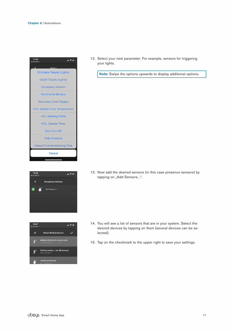
12. Select your next parameter: For example, sensors for triggering your lights.
Note: Swipe the options upwards to display additional options.
13. Now add the desired sensors (in this case presence sensors) by tapping on „Add Sensors...“.
14. You will see a list of sensors that are in your system. Select the desired devices by tapping on them (several devices can be se-lected).
15. Tap on the checkmark to the upper right to save your settings.

72Smart Home App
Chapter 8 | Automations
16. You are in the overview of the parameters you have already set. (currently your lights and the presence sensors).
17. Tap on „More settings...“ to select the next parameter.
Continue until you have set all the desired devices and parameters for this zone (check illustration).
If necessary, create additional zones and set the desired parameters for them as well.
Then go back via the arrow in the upper left corner to the overview page of the automations and save everything by tapping on the check-mark to the upper right.

73Smart Home App
Chapter 8 | Automations
8.2 Explanation of the configuration options
You have the option of making settings at the global and zone level. Global settings apply to all zones, but can be supplemented or overwritten by zone settings.
Most settings are available both globally and in the zones. However, there are also settings that you can only select either globally or in the zones.
Note: You will get a more detailed description in the app itself. To do this (after having selected it), tap on the option and hold it down briefly.
Dimmable LightsA collection of dimmable luminaires or luminaire groups. Please make sure to use only dimmable lumi-naires - on/off luminaires cannot be used here.
On/Off LightsA collection of simple on/off luminaires or luminaire groups.
Occupancy SensorsA collection of occupancy sensors available for ligh-ting control in the zone.
Illuminance SensorsA collection of illuminance sensors available in the zone for lighting control.
Secondary Zones TriggerDetermines the adjacent zones that trigger the current zone in secondary mode.
HCL: Sample Colour TemperaturesSpecifies the initial, average and final colour tempera-tures.HCL: Control IntervalMinimum period between commands sent in HCL mode.
HCL: Steering Profile Determines which colour control profile is used to implement Human Centric Lighting (HCL).
HCL: Sample TimesSpecifies the time of day for the initial, average and final colour temperature of the luminaires.
Daily Turn OffAt the specified time, a single switch-off command to the zone is executed.
Daily Schedule Determines at which time of day this automation is active i.e., reacts to changes in occupancy and illumi-nance.

74Smart Home App
Chapter 8 | Automations
Manual Override Blocking TimeIf users intervene manually via a switch or the app, the automatic lighting control is blocked for the time frame defined here.
Cut-off Control IntervalMinimum period between commands sent when in lux threshold control mode.
Hold Time Specifies the time during which the zone is still con-sidered occupied after presence sensors in the zone have reported an unoccupied state.
Hold Time (Secondary) Specifies the amount of time that must elapse without triggering a secondary zone before the zone is consi-dered unoccupied.
Standby Duration Specifies the period of time that the zone is still consi-dered occupied after all presence sensors in the zone have reported an unoccupied state.
Standby Duration (Secondary) Specifies the period of time the zone is still consi-dered occupied after all presence sensors in the zone have reported an unused/unoccupied state.
Control Loop Interval Minimum period between commands sent when in target lighting control mode.
Target Light Level Sets a lighting control threshold above which lumi-naires are switched off and below which they are switched on.
Cut-off Light Level Sets a threshold light level above which luminaires are switched off and below which luminaires are switched on.
Primary On-Level Determines the light level, in relation to the maximum achievable light level, that is applied when luminaires are switched on due to occupancy.
Secondary On-LevelDetermines at what percentage light level of the maxi-mum achievable light level luminaires are switched on when a secondary (adjacent) zone trigger is activated.
Primary Standby-Level Determines the light level, relative to the maximum achievable light level, that luminaires will apply when entering standby mode due to the absence of a prima-ry zone trigger. When unspecified its default value is set at 20%.
Secondary Standby-LevelDetermines the light level, relative to the maximum achievable light level, that luminaires will apply when entering standby mode due to the absence of a secondary zone trigger. When unspecified its default value is set at 20%.
PI: Integral Error GainGain (amplification) of the accumulated integral error fed back into the PI control loop.
PI: Proportional Error GainAmplification of the proportional error fed back into the PI control loop.
Transition Time On -> Off Defines the slope (ramp) used when switching from the on state to the off state.
Transition Time On -> Standby Defines the slope (ramp) used when switching from the on state to the standby state.
Transition Time Standby -> OffDefines the ramp used when switching from the stand-by state to the off state.
Note: Some of the configuration options have a default value set – even when not using/configuri-ng. Example: When not configuring the „power on level“, the value defaults to 70%.

75Smart Home App
Chapter 8 | Automations
8.3 Using an automation
After you have made all the necessary configurations for your automation and have saved them successfully (via the check mark in the upper right corner), you can name them and activate or deactivate them as required.
Naming the automation
1. Tap on the pencil to the upper right to enter the edit mode.2. Tap on automation and then enter the desired name using the
keyboard.
Activating/deactivating the automation
1. Tap on automation to activate or deactivate it. You can spot a running automation by the green arrow. An inactive automation is indicated by a grey arrow.
Note: In the case of a faulty automation, for example if you have added an on/off device to the dimmable destinations, the arrow will be marked with an exclamation mark. In this case, please check your configuration.

76Smart Home App
Chapter 8 | Automations
8.4 Description of the graphs for sample automations
When creating a new automation, you get a description at the beginning describing the functions, requirements etc. Furthermore, you will see two graphs representing samples of an automation. The first graph shows different phases within an automation. The second graph shows the progression of a daylight simulation (HCL): warm-white -> cool-white -> warm-white.
The following explanations describe the individual phases in the first graph:
(1) Transition Time Off ->OnThe occupancy sensor detects presence and initially regulates the ligh-ting to the defined switch-on level.
(2) Control Loop IntervalThe extended lighting control loop is designed to constantly set the target light level defined in lux. Phase 2 corresponds to the period between adjustments of the PI controller („control loop interval“). Illu-minance sensors and the set value in lux determine how much artificial light must be provided in this section to hit the target value. This light output is maintained within a control loop interval. A longer interval prevents frequent fluctuations in illuminance which can be perceived as disturbing; a shorter interval allows the target value to be achieved more accurately, as readjustments can be made more frequently.
(3) Transition Time for Changes by the PI ControllerThe PI controller continuously adjusts the light generation so that the actual value of the light level approaches the target value. Phase 3 indi-cates the transition time of 30 seconds that elapses between changes to the light output level by the PI controller. This prevents abrupt changes in illuminance, which might be perceived as disturbing, from occurring. Illuminance measurements implement the use of available daylight.
(4) Hold TimePhase 4 corresponds to the hold time. After the occupancy sensors no longer register occupancy, the luminaires remain at the light level the PI controller last set to reach the target light level.
(5) Transition Time On -> StandbyPhase 5 is the transition phase between the on-status and the standby-status. The duration for the period between the individual behavioural states can be individually set by you.

77Smart Home App
Chapter 8 | Automations
(6) Standby Duration and Standby LevelIn phase 6, the lighting system is in standby mode. By default, the light level here is set at 20 %. Duration and light level can be individually de-termined by you. If in this state a presence sensor is triggered, the light level returns to the last value determined by the PI controller.
(7) Transition Time Standby-OffPhase 7 describes the time period during which the lighting system changes from standby from the standby state to the off state. Each trig-ger when in the off state causes the luminaires to return to the switch-on level.
8.5 Automation samples
In this section you will find two samples for automations, including a list of the necessary devices and configura-tions to be made in the app:
Sample 1: Simple lighting automation in the entrance area
Desired situationWhen entering the flat, the light is to be switched on automatically for a predefined period of time (e.g. 30 sec.). If the entrance area is left, and no more movement is detected, the light should switch off automatically.
Device requirements• 1 motion detector (e.g. ceiling sensor)• 1 simple on/off or dimmable luminaire (e.g. Philips Hue or a lumi-
naire controlled via ubisys power switch S1(-R) or ubisys universal dimmer D1-(R)).
Necessary configuration optionsZone• On/Off luminaires - e.g. ceiling luminaire via power switch S1• Presence sensors - e.g. NYCE 3043 ceiling motion detector
Global or Zone• Hold time: 30 seconds• Standby duration: None

78Smart Home App
Chapter 8 | Automations
Sample 2: Office lighting with multiple luminaires and lighting sensors
Desired situationThe luminaires are to be switched on automatically as a group, by trig-gering any presence sensor. At the same time the illuminance is to be regulated to a predefined target light level.If the office is not occupied, the lighting should be automatically dim-med down to a predefined standby level and then switched off after a predefined standby duration.
Device requirement• 1 (or more) motion detectors• 1 (or more) illuminance sensors• Dimmable luminaires (configured as a group)
Required configuration optionsZone• Dimmable luminaires• Presence sensors• Illuminance sensors
Global or Zone• Standby duration• Target light level• Hold time• Switch-on value• Primary standby level
Optional configuration optionsGlobal• Transition time On -> Off• Transition time Off -> On• Transition time On -> Standby• Transition time Standby -> Off

79Smart Home App
Chapter 9Settings

80Smart Home App
Chapter 9 | Settings
9.1 Facilities
Via „Attachments“ you have the option of switching to another gateway or gaining access to another property (Facility). Proceed as follows:
1. Tap on: Settings (illustration)
2. Tap on „Facilities“. The number with a grey background indicates that there is one (or more) facility to which your smartphone has not yet connected.
3. Tap on the desired facility to change the property (highlighted in light grey = current installation). The facility marked „new“ is the system to which your smartphone/tablet smartphone/tablet has not yet connected to. If you want to access a system for the first time and it does not yet appear in the list, proceed as follows:
1. To update the displayed status, pull down to refresh the screen.
2. The facilities or gateways that have not yet been set up appear in the list. Grey background „new“ = already in the list for some time Blue background „new“ = just appeared in the list Find out the next steps in the section at the beginning (how to con-nect your Smartphone/Tablet with your Smart Home system).

81Smart Home App
Chapter 10Additional Functions and Notes

82Smart Home App
Chapter 10 | Additional Functions and Notes
10.1 Updates
ubisys regularly provides you with free software updates for your app. Follow the instructions of the respective app store to install an update.
10.2 Contact
ubisys technologies GmbHNeumannstr. 1040235 DüsseldorfGermany
T +49. 211. 54 21 55 – 00F +49. 211. 54 21 55 – 99