Smart Grid Division Distributed Generation in a Smart Grid · © Siemens AG 2013 All rights...
25
Distributed Generation in a Smart Grid Ken Geisler Vice President, Strategy NAM Smart Grid Division Infrastructure & Cities Sector Siemens Industry, Inc. Smart Grid Division
Transcript of Smart Grid Division Distributed Generation in a Smart Grid · © Siemens AG 2013 All rights...
© Siemens AG 2013 All rights reserved.
Distributed Generation in a Smart
Grid Ken Geisler
Vice President, Strategy NAM
Smart Grid Division
Infrastructure & Cities Sector
Siemens Industry, Inc.
Smart Grid Division
© Siemens AG 2013 All rights reserved.
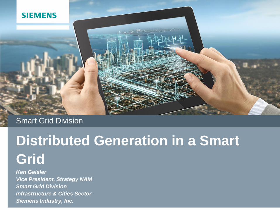
From centralized, unidirectional grid …
Unidirectional Power Flow Bidirectional Power Flow
… to distributed energy and bidirectional energy balancing
Offshore Wind Parks
Large Scale
PV Plant
Small Industrial
Gas Turbine
Biogas CHP Diesel Generator
Storage
Solutions
Electrical
Vehicles
Private Solar
Smart Street
Lighting
Hydrogen Storage
Storage
Solutions Pumped Storage
Power Plant
Page 2
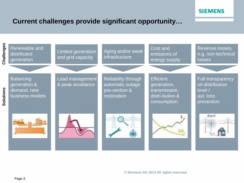
Distributed Generation driving changes in grid design
© Siemens AG 2013 All rights reserved.
Balancing
generation &
demand, new
business models
Efficient
generation,
transmission,
distri-bution &
consumption
Full transparency
on distribution
level /
aut. loss
prevention
Renewable and
distributed
generation
Limited generation
and grid capacity
Aging and/or weak
infrastructure
Cost and
emissions of
energy supply
Revenue losses,
e.g. non-technical
losses
Load management
& peak avoidance
Reliability through
automatic outage
pre-vention &
restoration
Ch
all
en
ges
S
olu
tio
ns
Page 3
Current challenges provide significant opportunity…
© Siemens AG 2013 All rights reserved.
IC CC
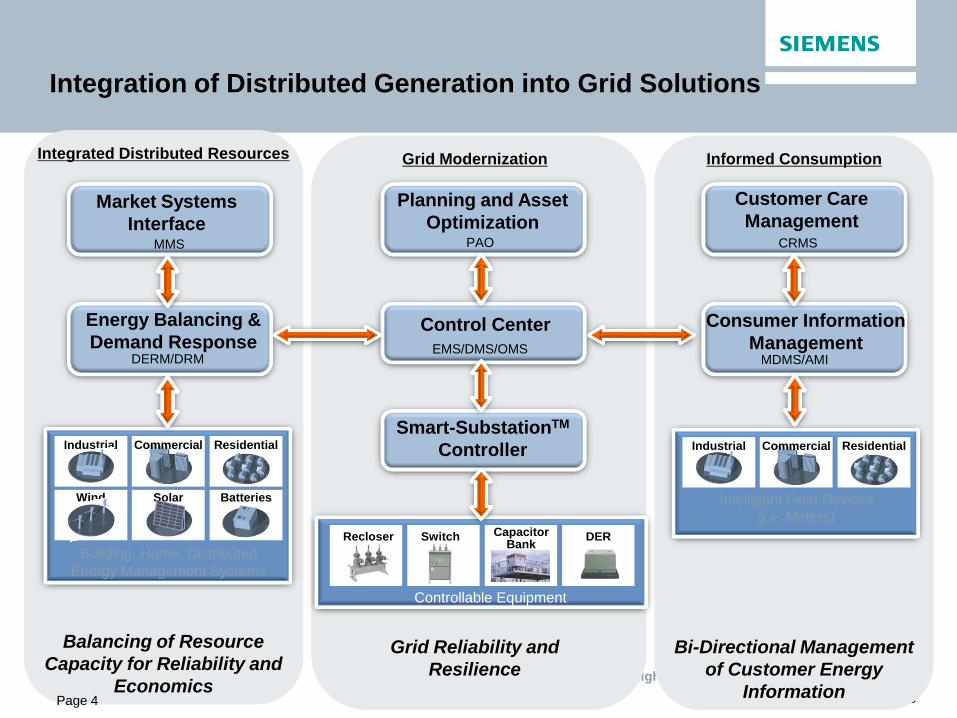
Customer Care
Management
Residential Industrial Commercial
Intelligent Field Devices
(i.e. Meters)
Building, Home, Distributed
Energy Management Systems
Residential
Batteries Solar
Industrial
Wind
Commercial
Planning and Asset
Optimization PAO
Control Center
EMS/DMS/OMS DERM/DRM MDMS/AMI
Smart-SubstationTM
Controller
Energy Balancing &
Demand Response Consumer Information
Management
DER
Controllable Equipment
Recloser Switch Capacitor Bank
Market Systems
Interface MMS CRMS
Balancing of Resource
Capacity for Reliability and
Economics
Integrated Distributed Resources
Grid Reliability and
Resilience
Grid Modernization
Bi-Directional Management
of Customer Energy
Information
Informed Consumption
Page 4
Integration of Distributed Generation into Grid Solutions
© Siemens AG 2013 All rights reserved.
IC CC Page 5
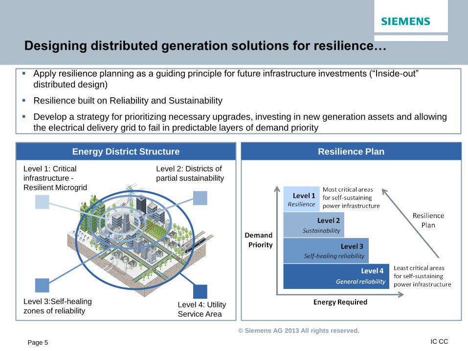
Resilience Plan
Apply resilience planning as a guiding principle for future infrastructure investments (“Inside-out”
distributed design)
Resilience built on Reliability and Sustainability
Develop a strategy for prioritizing necessary upgrades, investing in new generation assets and allowing
the electrical delivery grid to fail in predictable layers of demand priority
Energy District Structure
Level 3:Self-healing
zones of reliability
Level 2: Districts of
partial sustainability
Level 1: Critical
infrastructure -
Resilient Microgrid
Level 4: Utility
Service Area
Designing distributed generation solutions for resilience…

© Siemens AG 2013 All rights reserved.
IC CC 5/20/2013 IC CC Page 6
The imminent topic of resilience… The number of natural disasters is increasing
© Siemens AG 2013 All rights reserved.
Page 7
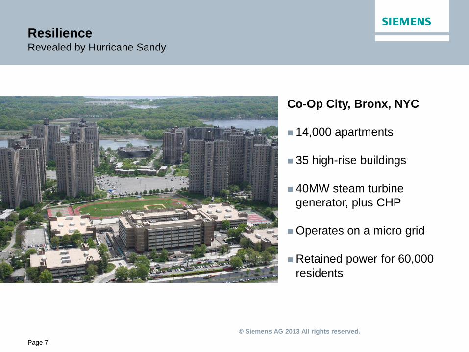
Resilience Revealed by Hurricane Sandy
Co-Op City, Bronx, NYC
14,000 apartments
35 high-rise buildings
40MW steam turbine
generator, plus CHP
Operates on a micro grid
Retained power for 60,000
residents

© Siemens AG 2013 All rights reserved.
IC CC
Distributed Generation Landscape
Page 8
Technology List Average Capacity for Building/
Community
Biomass – Dairy or Swine Manure
Biomass – Advanced Digester (Food Industry – Biogas Application)
Biomass – Landfill Gas (LFG)
Biomass – Waste Water Treatment Plant (WWTP)
550 kW electric
Up to 2,000 kW electric
5,000 kW electric (5MW)
Geothermal
Geothermal – Heat Pumps 150 tons cooling
Hydropower
Hydro – In Conduit 1100 kW electric
Solar
Solar – Photovoltaic Residential Fixed Tilt
Solar – Photovoltaic Commercial Fixed Tilt
Solar – Photovoltaic Ground Based Tracking
Solar – Integrated Space and Water Heating
Solar – Residential Water Heating
5.3 kW electric
138 kW electric
1500 kW electric
4.4 kW thermal
116 therms/year
Wind
Wind – Community Scale 5,000 kW (5MW)
Source: KEMA 2009 Cost of Generation Study for the California Energy Commission

© Siemens AG 2013 All rights reserved.
What is cogeneration/CHP?
The most effective and efficient form of power generation.
The process where single fuel source, such as natural gas, is used to produce
both electrical and thermal energy. Source: http://www.futureworldenergyinc.com/products/cogeneration/ http://energensolutions.com.au/cogeneration/ http://www.uschpa.org/i4a/pages/index.cfm?pageid=1
Page 9

© Siemens AG 2013 All rights reserved.
The typical U.S. power plant is only about 33% efficient, using
three units of fuel to produce one unit of electricity.
The rest gets turned into waste energy, mainly heat that's vented
into the atmosphere. Most plants can't recycle this heat because
they're located remotely, far from consumers, and heat cannot
travel far before turning cold.
This kind of energy production—called "central" generation—is
the dominant way of making power in the U.S.
CHP turns these numbers on their head, providing what the U.S.
EPA calls "an efficient, clean, and reliable approach to generating
electricity and heat energy from a single fuel source."
The key is that cogeneration plants generate energy on site at the
facility. That enables these facilities to recycle their waste heat
into clean electricity and useful steam, which can be used to warm
nearby buildings or to assist various industrial processes
Conventional Central Generation vs. CHP
CHP plant on-site
Heat recovery boiler
33%
Delivered
Electricity
40%
Thermal
Energy
Excess heat is recycled at a CHP plant (on-site at manufacturers or
other large institutions) through a heat recovery boiler. The
process recaptures about half the waste energy as thermal energy.
As a result, 73 units of usable energy are available.
Combined Heat and Power (Cogeneration)
average efficiency 73%
100%
fuel
27% waste heat
For every 100 units of fuel, approximately 67 units are released as
waste heat. About 3 more units are abandoned through
transmission line losses. As a result, only 30 units of power are
actually delivered to the customer.
30%
Delivered
Electricity
3% Line losses
Conventional Central Generation
average efficiency 30%
100%
fuel
67% waste heat
Power plant
Central CHP
Source: http://www.recycled-energy.com/main/combined_heat_power.html
Page 10
© Siemens AG 2013 All rights reserved.
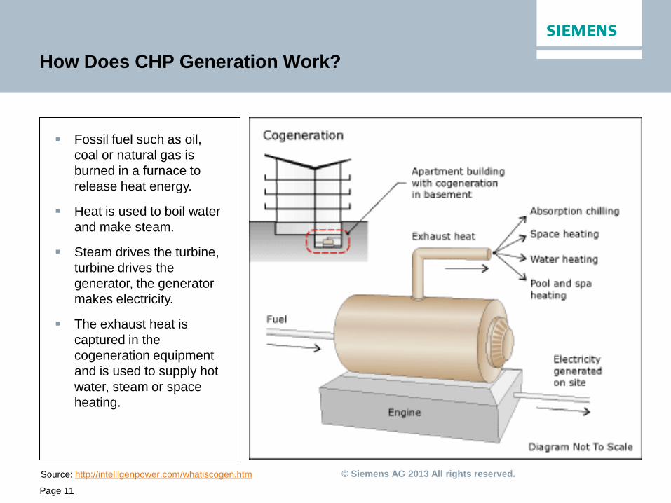
How Does CHP Generation Work?
Fossil fuel such as oil,
coal or natural gas is
burned in a furnace to
release heat energy.
Heat is used to boil water
and make steam.
Steam drives the turbine,
turbine drives the
generator, the generator
makes electricity.
The exhaust heat is
captured in the
cogeneration equipment
and is used to supply hot
water, steam or space
heating.
Source: http://intelligenpower.com/whatiscogen.htm
Page 11

© Siemens AG 2013 All rights reserved.
What are the benefits of cogeneration?
Source: December 2004: by Director John Herbert
Energy Savings Environmental
Uses fuel more efficiently, more watts per
dollar
Reduces pollution
Offers energy savings ranging between 15
40% when compared against the supply of
electricity and heat from conventional
power stations
Lowers emissions to the environment, in
particular CO2, the main greenhouse gas
by
30–50%
Provides lower transmission losses (since
it is located in close proximity of campus /
building)
Generated power is used by an individual
facility
Cogen plants are generally built closer to
populated areas, which requires them to
be held to higher environmental standards
Page 12
© Siemens AG 2013 All rights reserved. Source:http://www.cogeneration.org/111011Conf/Presentations/Haefke.pdf
40
50
60
70
80
90
100
1999
2001
1997
2009
1995
2003
2007
2005
2010
2008
2006
2004
2002
2000
1998
1996
Cu
mu
lati
ve C
ap
acit
y
Ad
dit
ion
s (
GW
)
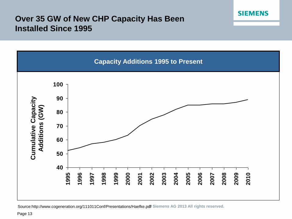
Capacity Additions 1995 to Present
Page 13
Over 35 GW of New CHP Capacity Has Been
Installed Since 1995
© Siemens AG 2013 All rights reserved. Source: http://www.electricchoice.com/electricity-prices-by-state.php
Page 14
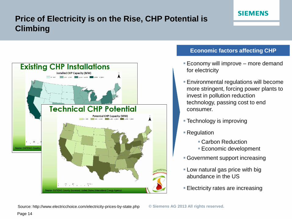
Price of Electricity is on the Rise, CHP Potential is
Climbing
Economy will improve – more demand
for electricity
Environmental regulations will become
more stringent, forcing power plants to
invest in pollution reduction
technology, passing cost to end
consumer.
Technology is improving
Regulation
Carbon Reduction
Economic development
Government support increasing
Low natural gas price with big
abundance in the US
Electricity rates are increasing
Economic factors affecting CHP
© Siemens AG 2013 All rights reserved.
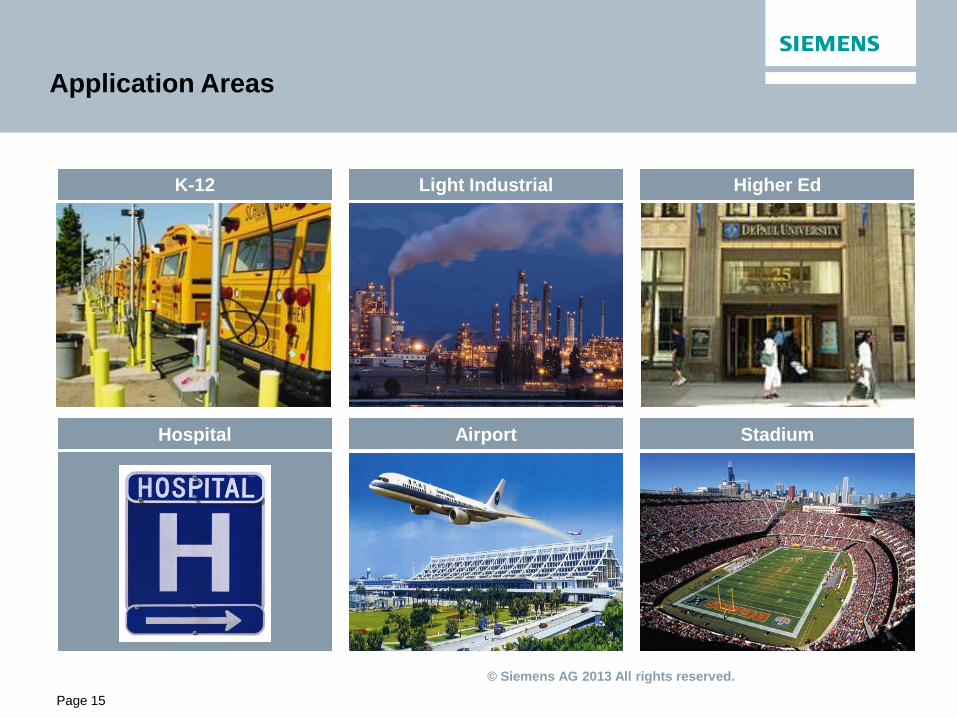
Airport
Light Industrial Higher Ed
Stadium Hospital
K-12
Page 15
Application Areas
© Siemens AG 2013 All rights reserved.
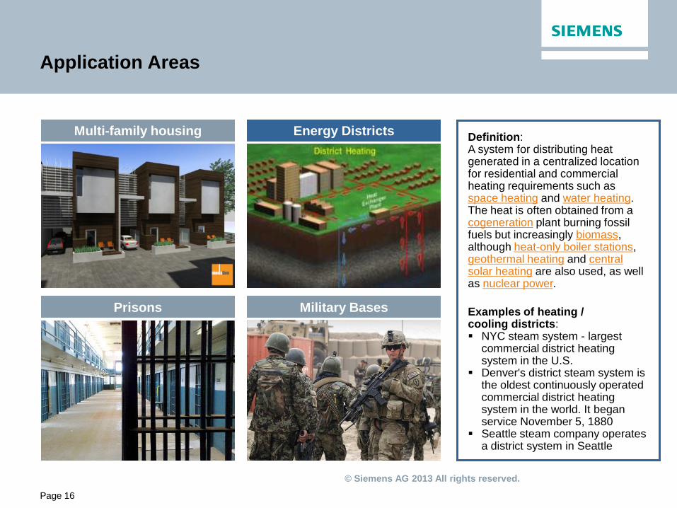
Application Areas
Definition: A system for distributing heat generated in a centralized location for residential and commercial heating requirements such as space heating and water heating. The heat is often obtained from a cogeneration plant burning fossil fuels but increasingly biomass, although heat-only boiler stations, geothermal heating and central solar heating are also used, as well as nuclear power.
Examples of heating / cooling districts: NYC steam system - largest
commercial district heating system in the U.S.
Denver's district steam system is the oldest continuously operated commercial district heating system in the world. It began service November 5, 1880
Seattle steam company operates a district system in Seattle
Prisons
Energy Districts Multi-family housing
Military Bases
Page 16

© Siemens AG 2013 All rights reserved.
Steam Turbines
Steam turbines for power generation,
combined heat & power and mechanical
drives for all industrial applications
Various design paradigms including:
• Pre–designed steam turbines up to 10 MW
• Industrial steam turbines up to 250 MW
Gas Turbines
Gas turbines for power generation,
combined heat & power and mechanical
drives for all industrial applications.
Small gas turbines from 5 up to 15 MW
Medium gas turbines from 18.5 up to 50 MW
Page 17
Siemens: Industrial Turbines for all Your Needs

© Siemens AG 2013 All rights reserved.
Background:
SRS, a nuclear reservation, built during the 1950s to refine
nuclear materials for deployment in nuclear weapons, was
experiencing challenges maintaining their 1950’s – vintage
boilers, and at the same time, meeting the requirements of
the Clean Air Act and other mandated improvements in
energy and increased use of renewable energy. SRS is
owned by DOE.
Replaced:
coal and oil-fired generation by incorporating a
biomass-fueled steam cogeneration plant and two smaller
biomass-fueled plants
Key benefits of project:
Annual energy reduction
Support of the S. Carolina Biomass Council Goals
Decrease of water intake from Savannah River,
supporting water conservation efforts in the region
Reduced its carbon footprint into the environment.
Government’s largest biomass – fueled cogeneration
facility in the country
Source: http://www.ameresco.com/sites/default/files/cs_savriver_v5.pdf
Location Aiken, South Carolina
Facility Size More than 300 sq. miles
Installation Costs $795 million
Annual Energy
Savings
$34.3 million – 1st year
Project date May 2009 – Dec 2011
Supplier Ameresco
Contract Duration 19 years
http://www.renewableenergyworld.com/rea/news/article/2012/02/excellence-in-renewable-energy-awards-winners-project-of-the-year-and-readers-choice?page=5
Page 18
Example Project: CHP Savannah River Site, in Aiken, SC
(largest energy efficient project in nation’s history)

© Siemens AG 2013 All rights reserved.
Background:
The heavily co-funded project included
sponsorship by the Museum, the US DOE, the Gas
Technology Institute (GTI), and both the City of
Chicago, and the State of Illinois.
GTI served as the US DOE project manager and Ballard
Engineering (Rockford, IL) was selected as the design and
installation engineering firm.
Outcome:
The system is located on the second floor of the museum
in a partitioned area adjacent to an existing exhibit space.
Plans include incorporating the CHP system as part of an
exhibit on distributed generation
Equipment Cost $1,723,125
Annual Energy
Cost Savings
Approx. $200,000
Simple Payback Est: 8.6 Years
Fuel Use Efficiency 60.5% (38.3% electric; 22.2% thermal)
System Online February 2003
Supplier Ballard Engineering
http://www.midwestcleanenergy.org/profiles/ProjectProfiles/MuseumScienceIndustry.pdf
Page 19
Example Project: CHP in Chicago –
Museum of Science & Industry
© Siemens AG 2013 All rights reserved.
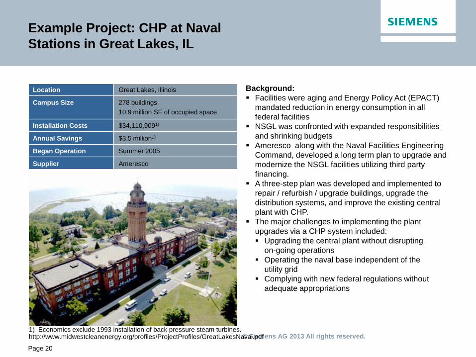
Example Project: CHP at Naval
Stations in Great Lakes, IL
1) Economics exclude 1993 installation of back pressure steam turbines. http://www.midwestcleanenergy.org/profiles/ProjectProfiles/GreatLakesNaval.pdf
Location Great Lakes, Illinois
Campus Size 278 buildings
10.9 million SF of occupied space
Installation Costs $34,110,9091)
Annual Savings $3.5 million1)
Began Operation Summer 2005
Supplier Ameresco
Background:
Facilities were aging and Energy Policy Act (EPACT)
mandated reduction in energy consumption in all
federal facilities
NSGL was confronted with expanded responsibilities
and shrinking budgets
Ameresco along with the Naval Facilities Engineering
Command, developed a long term plan to upgrade and
modernize the NSGL facilities utilizing third party
financing.
A three-step plan was developed and implemented to
repair / refurbish / upgrade buildings, upgrade the
distribution systems, and improve the existing central
plant with CHP.
The major challenges to implementing the plant
upgrades via a CHP system included:
Upgrading the central plant without disrupting
on-going operations
Operating the naval base independent of the
utility grid
Complying with new federal regulations without
adequate appropriations
Page 20

© Siemens AG 2013 All rights reserved.
Page 21
Example Project: CHP at Evanston Township
High School in Evanston, IL
Facility Size 10 Buildings (1.3 Million sq. ft.)
CHP Equipment installed
(3) 800 kW Caterpillar Model 3516
Natural Gas Engine Generators
(3) Maxim Exhaust Heat Recovery Silencer Units
(4) York 520-ton Single-Stage Steam-Fired Absorption Chillers
Generating Capacity
2.4 MW
Heat Recovery 3,600 lb/hr of 110 psig steam
Installation Date October 1992
Installed Cost $1.5 Million
Simple Payback 4.2 Years
Current Annual Energy Savings
$354,000
Supplier Unable to locate
Background:
In the early 1990’s, when the school began looking for
ways to lower energy costs, ETHS discovered that the
combination of a central boiler plant and central absorption
cooling system made it an excellent candidate for a CHP
system.
(CHP) system of Evanston Township High School (ETHS)
supplies 2.4 megawatts of electricity and 110 psig steam to
the 10 contiguous buildings located on the 65 acre
campus. The CHP system operates three 800 kW
Caterpillar Model 3516 Natural Gas Engine Generators
with three Maxim exhaust heat recovery silencers that
recover 1,200 lb/hr each of 100 – 110 psig steam when
operating at full load. The steam is utilized to provide
building heat, domestic hot water and absorption cooling to
the campus.
http://www.midwestcleanenergy.org/profiles/ProjectProfiles/EvanstonTownshipHS.pdf
© Siemens AG 2013 All rights reserved.
IC CC IC CC Page 22
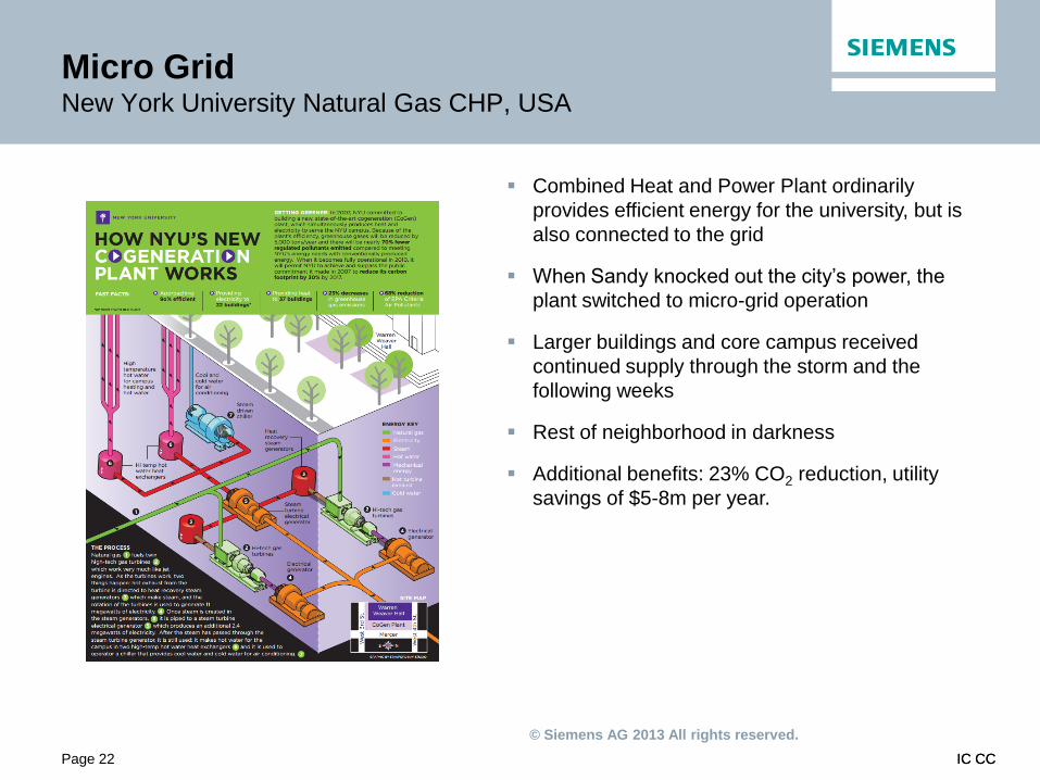
Micro Grid New York University Natural Gas CHP, USA
Combined Heat and Power Plant ordinarily
provides efficient energy for the university, but is
also connected to the grid
When Sandy knocked out the city’s power, the
plant switched to micro-grid operation
Larger buildings and core campus received
continued supply through the storm and the
following weeks
Rest of neighborhood in darkness
Additional benefits: 23% CO2 reduction, utility
savings of $5-8m per year.

© Siemens AG 2013 All rights reserved.
IC CC IC CC Page 23
Virtual Power Plant Munich, Germany
Initiative of Munich City Utilities & Siemens
Small-scale, distributed energy sources pooled &
operated as single installation
Improves reliability of planning & forecasting
decentralized sources
Promotes efficient use of decentralized energy, &
greater diversity of sources
Enables decentralized sources to operate flexibly
either as a single unit, or in island-mode to serve a
more localized network
Includes cogeneration modules (8MW),
hydropower & wind farm (12MW)
Distributed Energy Management System

© Siemens AG 2013 All rights reserved.
IC CC Page 24
Siemens offers a broad range of energy efficient
and sustainable solutions
Power Distribution
Renewable Power
Generation
Fossil Power Generation
Lighting (Osram) Solutions for
Industry
Building Technologies
Power Transmission
Environmental Technologies
Mobility
IT Solutions and Services
Healthcare

© Siemens AG 2013 All rights reserved.
Thank you for your attention
Ken Geisler
Vice President, Strategy NAM
Smart Grid Division
Infrastructure & Cities Sector
Siemens Industry, Inc
E-mail:
Answers for infrastructure and cities.