
SMART FOUNDATION™ MANUAL - Southwest …windenergy.com/sites/ · Instructions for Assembly and...
32
Southwest Windpower, Inc. 1801 West Route 66 Flagstaff, Arizona 86001 USA Phone: 928-779-9463 Fax: 928-779-1485 www.skystreamenergy.com SMART FOUNDATION™ MANUAL © March 2009 Southwest Windpower, Inc. All Rights Reserved
Transcript of SMART FOUNDATION™ MANUAL - Southwest …windenergy.com/sites/ · Instructions for Assembly and...

Instructions for Assembly and Installation of SMarT_Foundation™ Kits (U.S. Patent Pending) for the Skystream Wind Turbine
SMarT_Foundation™ [S
Step 6. Join the upper and lower anchor bolt templates. Follow the illustrations from left to right.
imple Modular Technology] SMarT 2_v2 March 12, 2008 © 2007–2008 by AnemErgonics, LLC. All rights reserved. Page 8 of 22
Southwest Windpower, Inc.1801 West Route 66Flagstaff, Arizona 86001 USAPhone: 928-779-9463Fax: 928-779-1485
www.skystreamenergy.com
SMART FOUNDATION™ MANUAL
© March 2009 Southwest Windpower, Inc. All Rights Reserved

SMarT_Foundation™ [Simple Modular Technology]Assembly and Installation Instructions
(U.S. Patent Pending)
Southwest Windpower Skystream 3.7 Wind Turbine with Towers up to 60 ft. (18.3 m) in Height
DESIGNED IN CONFORMANCE WITH THE INTERNATIONAL ELECTROTECHNICAL COMMISSION (IEC) 61400-2 ED.2 DESIGN REQUIREMENTS FOR SMALL WIND TURBINES
THE NATIONAL ELECTRICAL SAFETY CODE (NESC) AND THE INTERNATIONAL BUILDING CODE (IBC) 2003 PRESCRIPTIVE SOIL VALUES
ATTENTIONUSE OF THESE INSTRUCTIONS, WHICH ARE PROVIDED BY ANEMERGONICS, LLC (“SUPPLIER”) IS CONTROLLED BY, GOVERNED BY AND SUBJECT TO THE APPLICABLE ANEMERGONICS, LLC PURCHASE AGREEMENT, WHICH INCLUDES THE ANEMERGONICS, LLC TERMS AND CONDITIONS (“AGREEMENT”). ANY USE OF THESE INSTRUCTIONS THAT IS IN ANY WAY INCONSISTENT WITH THE AGREEMENT IS UNAUTHORIZED. AMONG OTHER THINGS, THE AGREEMENT INCLUDES: BROAD INDEMNITY PROVISIONS IN FAVOR OF SUPPLIER AND THE SUPPLIER INDEMNIFIED PARTIES (AS DEFINED IN THE AGREEMENT), LIABILITY LIMITATION AND LIMITATIONS ON USE. CONTACT SUPPLIER WITH QUESTIONS REGARDING THE AGREEMENT OR IF YOU HAVE NOT BEEN PROVIDED THE AGREEMENT OR ANY OF THE MATERIALS REFERENCED IN THE AGREEMENT.
© 2007–2008 by AnemErgonics, LLC. All rights reserved.
AnemErgonics™
A Colorado Limited Liability Company www.anemergonics.com
2 Skystream SMarT Foundation™ Manual Rev A

Instructions for Assembly and Installation of SMarT_Foundation™ Kits (U.S. Patent Pending) for the Skystream Wind Turbine
☺Some Important Notes about Constructing a SMarT Foundation!
� Check with local building officials to determine the design wind speed at the location where you are installing the wind turbine.� Check with local building officials to determine the design frost depth at the location where you are installing the wind turbine. If the frost depth
is more than 3.5 ft. (1.07 m), you will need to fabricate an extension for the stanchion in the foundation kits (the “Kit”). � Check that the excavation diameter from the construction drawings (the “Drawings) coincides with your tower height and design wind speed. � Check that the bolt circle of your tower base flange matches the bolt circle of the anchor bolt templates and rebar hoops in the Kit. � Check that you have ordered fiber-reinforced concrete as specified in the Drawings. � Modifications, including design modifications and use of additional or alternative materials supplied by third parties, must be pre-approved in
writing by Supplier. Any approvals referenced in these Instructions means Supplier’s prior, written approval.
� Make sure you read the Drawings, Instructions and Terms and Conditions carefully. � Make sure all Parts, materials and tools are in hand before gathering at the construction site. � Make sure the construction team is familiar with the Kit before gathering at the construction site.
� Follow the assembly sequence to avoid mistakes that might cause delays or other problems. � Have one person in charge of coordinating the participants and directing construction activity. � Conduct a site safety meeting to discuss procedures, roles and responsibilities before commencing construction activities. � Do not place excavation spoils (the pile of dirt!) close to the excavation. Avoid tripping hazards and keep dirt out of the foundation.
� Make sure the width of the excavation is at least that specified in the Drawings. � Level the center of the excavation floor where the stanchion base will be placed. � Mark the center of the excavation floor for placement of the stanchion. � Do not allow dirt or other loose materials to fall into the foundation. � Make sure that the anchor rods extend the correct height above the “stub pier” and the final grade. � Check the bill of lading when the concrete arrives to make sure the supplier has delivered fiber-reinforced concrete.� Do not torque the anchor rod nuts until the concrete has achieved its design strength of 2,500 psi. The required curing time depends on the initial
strength of the concrete and the cure conditions.
� Contact us with questions or if you encounter problems with the installation.
� Please reuse or recycle all materials remaining after construction.
SMarT_Foundation™ [Simple Modular Technology] SMarT 2_v2 March 12, 2008 © 2007–2008 by AnemErgonics, LLC. All rights reserved. Page 2 of 22 Skystream SMarT Foundation™ Manual Rev A 3

Instructions for Assembly and Installation of SMarT_Foundation™ Kits (U.S. Patent Pending) for the Skystream Wind Turbine
We provide a unique foundation solution along with Drawings, Parts and Instructions to facilitate placement of reinforcement and anchor rods.
We suggest a sequence of tasks for assembly and installation of the Kit and placement of concrete. However, it is the installer that is responsible for apply-ing appropriate techniques and exercising reasonable standards of care in constructing the foundation. The installer is also responsible for adhering to all applicable safety and health regulations and exercising reasonable prudence during construction. Consult the turbine manufacturer and/or qualified profes-sionals regarding lightning protection and electrical grounding requirements. Those issues are not addressed by us and are not our responsibility. Specifi-cation of installation procedures for anchor bolts or anchor rods is the responsibility of the turbine manufacturer. Proper installation, inspection and testing of anchor rods are the responsibility of the installer. Please check with the turbine manufacturer for its recommended procedures.
Use of this innovative foundation is intended to reduce material costs, labor hours and wind turbine in-stalled cost. Installers are advised to read the Drawings, Instructions and Terms and Conditions and to plan carefully.
ITEM PART NUMBER PART NAME DESCRIPTION QTY1 015-001-0001 STANCHION BASE 1/2" MDF x 19" OUTSIDE DIMENSION 12 013-003-0003 LOWER STANCHION 3" ABS PIPE X 23-15/16" 13 002-001-001 STANCHION BRACE 16 GA COLD ROLLED STEEL 24 014-001-0001/2 REBAR HOOP #3 STEEL 18 1/2" ID (17" BC) or 20-1/2" ID (19" BC) 45 009-002-001 STANCHION COUPLING 3" ABS 16 013-003-0004 UPPER STANCHION 3" ABS PIPE X 17-1/16" 17 009-006-0001 3" TO 2" ABS REDUCER 3" to 2" ABS REDUCER 18 013-001-0003 2" ABS EXTENSION 2" ABS PIPE x 2" 18 013-001-0003 2" ABS TEMPLATE SPACER 2" ABS PIPE x 2" 19 016-001-0004/6 LOWER ANCHOR BOLT TEMPLATE 1/2" MDF, 17" or 19" BOLT CIRCLE 1
10 008-003-002 CABLE TIE Plastic Tie, 7" 2011 009-004-0001 2" ABS FEMALE ADAPTER 2" ABS 212 009-005-0001 2" ABS MALE ADAPTER 2" ABS 213 016-001-0003/5 UPPER ANCHOR BOLT TEMPLATE 1/2" MDF, 17" or 19" BOLT CIRCLE 114 009-007-0001 1" PVC RISER 1" SCH 80 PVC PIPE X 6", THREADED 115 009-001-0002 1" PVC THREADED CAP 1" PVC 116 013-002-0001 1-1/2" ABS TEMPLATE SPACER 1-1/2" ABS PIPE X 3-15/32" 817 009-004-0002 1" PVC FEMALE ADAPTER 1" PVC 118 013-001-0002 1" PVC EXTENSION 1" PVC PIPE X 11-15/16" 119 009-003-0001 1" PVC ELBOW 1" PVC 90 DEGREE ELBOW WITH BELL END 120 008-001-0001 ANCHOR ROD* 1-1/4" x 32" ASTM 1554 821 008-002-0001 ANCHOR ROD NUT* 1-1/4" ASTM A563 HEAVY, HDG 2422 006-001-0001 CYLINDRICAL CONCRETE FORM 24" ID X 7-3/4" LONG 123 003-001-0002 LOCATER BRACKET 16 GA COLD ROLLED STEEL, 3/4" X 9-5/8" 424 008-005-0001 LOCATER BRACKET SCREWS #8 x 1/2" SELF TAPPING SCREW, PHILLIPS 825 011-001-0001 GUY ROPES GUY ROPE WITH SLIDES, 10' LONG, 2/PKG 226 012-001-0001 NAIL PEGS NAIL PEGS, 10" LONG, 4/PKG 127 017-001-0001 MULTI-PURPOSE CEMENT 2 OZ DABBER CAN 128 018-001-0003 DRAWINGS SMarT 2_v1 DRAWINGS 129 018-002-0002 INSTRUCTIONS SMarT 2_v1 ASSEMBLY/INSTALLATION INSTRUCTIONS 1
* Anchor Rods and Anchor Rod Nuts are sold separately.
The Kit requires an excavation of 3.5 feet (1.07 m) below the planned final earth grade. Thus, the founda-tion is suitable for use in frost depths up to and including 3.5 feet (1.07 m). The appropriate frost depth must be determined by consulting local building authorities. For frost depths greater than 3.5 feet (1.07 m), the installer must fabricate a 3” ABS pipe extension, the length of which is given by the equation l = frost depth – 42 inches (1067 mm). Using a standard 3” ABS coupling, this extension would be added to the bot-tom of the stanchion (Step 4.1).
The required foundation diameter, which depends on the tower height and the site design wind speed, is specified in the Drawings also con-tained in the Kit.
SMarT_Foundation™ [Simple Modular Technology] SMarT 2_v2 March 12, 2008 © 2007–2008 by AnemErgonics, LLC. All rights reserved. Page 3 of 22 4 Skystream SMarT Foundation™ Manual Rev A

Instructions for Assembly and Installation of SMarT_Foundation™ Kits (U.S. Patent Pending) for the Skystream Wind Turbine
SMarT_Foundation™ [S
Step 4. Assemble the vertical stanchion. Follow the illustrations from left to right.
imple Modular Technology] SMarT 2_v2 March 12, 2008 © 2007–2008 by AnemErgonics, LLC. All rights reserved. Page 4 of 22 Skystream SMarT Foundation™ Manual Rev A 5

Instructions for Assembly and Installation of SMarT_Foundation™ Kits (U.S. Patent Pending) for the Skystream Wind Turbine
Step Instructions Notes1 Check the contents of the Kit against the parts list
shown on page 3. Contact the Supplier if any parts are missing.
The Kit is used to assemble and properly locate the anchor bolt templates, spacers, rein-forcement and cylindrical concrete form on a vertical stanchion to be placed in the founda-tion excavation.
2 Read these Instructions carefully, paying close at-tention to safety issues.
Review the Drawings provided and Terms and Conditions provided with the Kits.
3 Gather all required tools and equipment. Tools required for Kit assembly and placement are a tape measure, carpenter’s level, ham-mer, Phillips head screwdriver, marking pen and cleanup rag. Typical concrete placement and finishing tools are required to pour the foundation. Personal protection equipment, in-cluding work gloves, eye protection and hard hat is required.
4 Assemble the vertical stanchion.
1. If necessary, add an extension (not supplied) to the Lower Stanchion (2) to deal with greater frost depths.
2. Insert the Lower Stanchion in the Stanchion Base (1) and place it on a solid, level surface convenient for assembly of the Kit.
3. Slide the two Stanchion Braces (3) over the top of the Lower Stanchion and rest them on the Stanchion Base.
4. Place the Rebar Hoops (4) over the Lower Stanchion and rest them on the Stanchion Braces.
5. Use the Stanchion Coupling (5) to connect the Upper Stanchion (6) to the Lower Stanchion. These parts should be glued together.
6. Install the 3” to 2” ABS Pipe Reducer (7) and the 2”ABS Extension (8), in that order, on top of the Upper Stanchion. These parts should be glued together.
Note: The Kit may be constructed in the excavation or at an adjacent location. Consider that when assembled it weighs approximately 145 lbs (66 kg).
The Lower Stanchion is the longer of the two 3” ABS pipes supplied with the Kit. Important: For frost depths greater than 3.5 feet (1.07 m), the installer must provide an ABS coupling and pipe extension of length l = frost depth – 42 inches (1067 mm).
Important: The use of ABS cement, or the Multi-Purpose Cement (27) supplied with the Kit, is required to attach these ABS fittings
Important: The use of ABS cement, or the Multi-Purpose Cement (27) supplied with the Kit, is required to attach these ABS fittings.
Note: You may find that the parts of Steps 4.5 and 4.6 were pre-assembled at the factory.
SMarT_Foundation™ [Simple Modular Technology] SMarT 2_v2 March 12, 2008 © 2007–2008 by AnemErgonics, LLC. All rights reserved. Page 5 of 22
6 Skystream SMarT Foundation™ Manual Rev A

Instructions for Assembly and Installation of SMarT_Foundation™ Kits (U.S. Patent Pending) for the Skystream Wind Turbine
SMarT_Foundation™ [S
Step 6. Join the upper and lower anchor bolt templates. Follow the illustrations from left to right.
imple Modular Technology] SMarT 2_v2 March 12, 2008 © 2007–2008 by AnemErgonics, LLC. All rights reserved. Page 8 of 22 Skystream SMarT Foundation™ Manual Rev A 7

Instructions for Assembly and Installation of SMarT_Foundation™ Kits (U.S. Patent Pending) for the Skystream Wind Turbine
Step Instructions Notes5 Assemble the anchor bolt templates.
1. Insert a 2” ABS Male Adapter (12) through the center of the Lower Anchor Bolt Template (9) into a 2” ABS Female Adapter (11). Hand-tighten the threaded fittings.
2. Insert a 2”ABS Template Spacer (8) into the 2”ABS Male Adapter. These parts should notbe glued together.
3. Install the assembly (from Steps 5.1 and 5.2) onto the stanchion by inserting the 2”ABS Fe-male Adapter into the 2” ABS Pipe Extension on the top of the stanchion. These parts should be glued together.
4. Insert a 2” ABS Male Adapter (12) through the center of the Upper Anchor Bolt Template (13) into a 2” ABS Female Adapter (11). Hand-tighten the threaded fittings.
5. Screw the 1” PVC Threaded Cap (15) onto one end of the 1” PVC Riser (14). Insert this as-sembly through any one of the inner holes of the Upper Anchor Bolt Template.
Note: The Lower Anchor Bolt Template has four long “spokes” and four short “spokes”.
Caution: For this assembly, the 2” ABS Female Adapter fits on the grooved side of the Lower Anchor Bolt Template.
Important: Do not cement these parts.
Important: The use of ABS cement, or the Multi-Purpose Cement (27) supplied with the Kit, is recommended to attach these ABS fittings.
The Upper Anchor Bolt Template has eight “spokes” that are the same size.
Caution: For this template, the 2” ABS Male Adapter fits on the grooved side of the Up-per Anchor Bolt Template.
SMarT_Foundation™ [Simple Modular Technology] SMarT 2_v2 March 12, 2008 © 2007–2008 by AnemErgonics, LLC. All rights reserved. Page 7 of 22
8 Skystream SMarT Foundation™ Manual Rev A

Instructions for Assembly and Installation of SMarT_Foundation™ Kits (U.S. Patent Pending) for the Skystream Wind Turbine
SMarT_Foundation™ [S
Step 6. Join the upper and lower anchor bolt templates. Follow the illustrations from left to right.
imple Modular Technology] SMarT 2_v2 March 12, 2008 © 2007–2008 by AnemErgonics, LLC. All rights reserved. Page 8 of 22 Skystream SMarT Foundation™ Manual Rev A 9

Instructions for Assembly and Installation of SMarT_Foundation™ Kits (U.S. Patent Pending) for the Skystream Wind Turbine
Step Instructions Notes6 Join the Upper and Lower Anchor Bolt Templates.
1. Join the Upper and Lower Anchor Bolt Tem-plates by inserting the 2” ABS Female Adapter on the bottom of the Upper Anchor Bolt Tem-plate into the 2” ABS Template Spacer pro-truding from the top of the Lower Anchor Bolt Template assembly. These parts should not be glued together.
2. Slip the eight 1-1/2” ABS Template Spacers (16) between the Upper and Lower Anchor Bolt Templates and align them with the outer bolt holes in the templates.
3. Assemble the 1” PVC Female Adapter (17), the 1” PVC Extension (18) and the 1” PVC El-bow (19) as shown in the illustration. These parts should be glued together
4. Screw the 1” PVC Female Adapter of the above assembly into the 1” PVC Threaded Nipple protruding from the bottom of the Lower Anchor Bolt Template.
Important: Make sure the 1” PVC Threaded Nipple passes through one of the inner holes in both the Upper and Lower Anchor Bolt Templates.
Important: Do not cement these parts.
Important: The use of PVC cement, or the Multi-Purpose Cement (27) supplied with the Kit, is recommended to attach these PVC fittings.
If necessary, this PVC assembly may be relocated to some other holes in order to mate with a planned electrical interconnection.
SMarT_Foundation™ [Simple Modular Technology] SMarT 2_v2 March 12, 2008 © 2007–2008 by AnemErgonics, LLC. All rights reserved. Page 9 of 22
10 Skystream SMarT Foundation™ Manual Rev A

Instructions for Assembly and Installation of SMarT_Foundation™ Kits (U.S. Patent Pending) for the Skystream Wind Turbine
SMarT_Foundation™ [S
Step 7. Install the anchor rods. Follow the illustrations from left to right.
imple Modular Technology] SMarT 2_v2 March 12, 2008 © 2007–2008 by AnemErgonics, LLC. All rights reserved. Page 10 of 22 Skystream SMarT Foundation™ Manual Rev A 11

Instructions for Assembly and Installation of SMarT_Foundation™ Kits (U.S. Patent Pending) for the Skystream Wind Turbine
Step Instructions Notes7 Install the anchor rods.
1. Prepare the eight 1-1/4” diameter Anchor Rods (20) as shown in the illustration above. 1.1. Remove the Anchor Rod Nuts (21) from
the bottom (short thread length) of the Anchor Rods.
1.2. Run one Anchor Rod Nut to the bottom of the thread length on the top of the Anchor Rods.
1.3. Mark the Anchor Rods in the locations shown. These marks will be used to place the rebar hoops.
2. Insert the Anchor Rods through the outer (bolt circle) holes of the Lower Anchor Bolt Tem-plate, the 1-1/2” ABS Template Spacers and the Upper Anchor Bolt Template.
3. Thread the Anchor Rod Nuts onto the protrud-ing Anchor Rods until they are just flush with the ends.
4. Adjust the lower Anchor Rod Nuts until they are snug with the Lower Anchor Bolt Tem-plate.
5. Before advancing to the next step, check that the top surfaces of the top Anchor Rod Nuts are flush with the top surfaces of the Anchor Rods and that the entire assembly is rigid. This may require additional hand tightening of some nuts.
Note: Anchor Rods are supplied separately from the Kit. The illustrations above and these Instructions have been prepared for the Anchor Rods provided by the Supplier. If different types or sizes of concrete anchors are supplied by others, appropriate adaptations must be made.
It is not unusual for minor thread damage to exist. In such cases, external threads may be “dressed” with a metal file and/or both internal and external threads may be “chased” by us-ing a wrench to force the nut past the damaged thread(s).
A wrench is not needed. Hand tightening is adequate.
A wrench is not needed. Hand tightening is adequate.
A wrench is not needed. Hand tightening is adequate.
SMarT_Foundation™ [Simple Modular Technology] SMarT 2_v2 March 12, 2008 © 2007–2008 by AnemErgonics, LLC. All rights reserved. Page 11 of 22
12 Skystream SMarT Foundation™ Manual Rev A

Instructions for Assembly and Installation of SMarT_Foundation™ Kits (U.S. Patent Pending) for the Skystream Wind Turbine
SMarT_Foundation™ [S
Step 8. Install reinforcement on anchor rod assembly. Follow the illustrations from left to right.
imple Modular Technology] SMarT 2_v2 March 12, 2008 © 2007–2008 by AnemErgonics, LLC. All rights reserved. Page 12 of 22 Skystream SMarT Foundation™ Manual Rev A 13
Instructions for Assembly and Installation of SMarT_Foundation™ Kits (U.S. Patent Pending) for the Skystream Wind Turbine
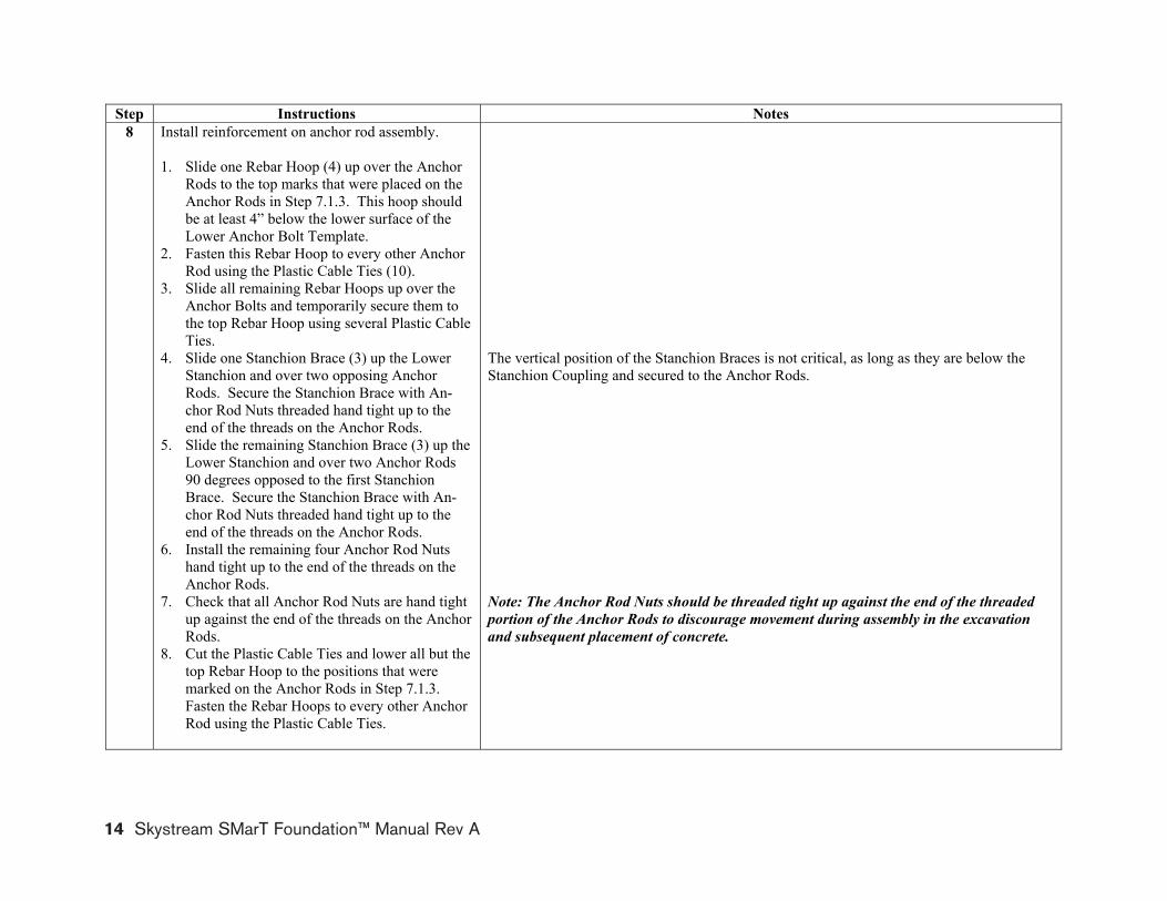
Step Instructions Notes8 Install reinforcement on anchor rod assembly.
1. Slide one Rebar Hoop (4) up over the Anchor Rods to the top marks that were placed on the Anchor Rods in Step 7.1.3. This hoop should be at least 4” below the lower surface of the Lower Anchor Bolt Template.
2. Fasten this Rebar Hoop to every other Anchor Rod using the Plastic Cable Ties (10).
3. Slide all remaining Rebar Hoops up over the Anchor Bolts and temporarily secure them to the top Rebar Hoop using several Plastic Cable Ties.
4. Slide one Stanchion Brace (3) up the Lower Stanchion and over two opposing Anchor Rods. Secure the Stanchion Brace with An-chor Rod Nuts threaded hand tight up to the end of the threads on the Anchor Rods.
5. Slide the remaining Stanchion Brace (3) up the Lower Stanchion and over two Anchor Rods 90 degrees opposed to the first Stanchion Brace. Secure the Stanchion Brace with An-chor Rod Nuts threaded hand tight up to the end of the threads on the Anchor Rods.
6. Install the remaining four Anchor Rod Nuts hand tight up to the end of the threads on the Anchor Rods.
7. Check that all Anchor Rod Nuts are hand tight up against the end of the threads on the Anchor Rods.
8. Cut the Plastic Cable Ties and lower all but the top Rebar Hoop to the positions that were marked on the Anchor Rods in Step 7.1.3. Fasten the Rebar Hoops to every other Anchor Rod using the Plastic Cable Ties.
The vertical position of the Stanchion Braces is not critical, as long as they are below the Stanchion Coupling and secured to the Anchor Rods.
Note: The Anchor Rod Nuts should be threaded tight up against the end of the threaded portion of the Anchor Rods to discourage movement during assembly in the excavation and subsequent placement of concrete.
SMarT_Foundation™ [Simple Modular Technology] SMarT 2_v2 March 12, 2008 © 2007–2008 by AnemErgonics, LLC. All rights reserved. Page 13 of 22
14 Skystream SMarT Foundation™ Manual Rev A

Instructions for Assembly and Installation of SMarT_Foundation™ Kits (U.S. Patent Pending) for the Skystream Wind Turbine
SMarT_Foundation™ [S
Step 9. Install the cylindrical concrete form. Follow the illustrations from left to right.
imple Modular Technology] SMarT 2_v2 March 12, 2008 © 2007–2008 by AnemErgonics, LLC. All rights reserved. Page 14 of 22 Skystream SMarT Foundation™ Manual Rev A 15

Instructions for Assembly and Installation of SMarT_Foundation™ Kits (U.S. Patent Pending) for the Skystream Wind Turbine
Step Instructions Notes9 Install the cylindrical concrete form.
1. Carefully slip the Cylindrical Concrete Form (22) over the anchor bolt assembly and let it rest on the ground.
2. Install the four Locater Brackets (23) on the long “spokes” of the Lower Anchor Bolt Tem-plate. Use the Locater Bracket Screws (24) provided and the pre-drilled holes in the Lower Anchor Bolt Template.
3. Raise the Cylindrical Concrete Form and cap-ture it in the bottom tabs of the four Locater Brackets. Fasten the Cylindrical Concrete Form in this position using the self threading Locater Bracket Screws provided and the pre-drilled holes in the Locator Brackets.
Important: Make sure the bottom of the Cylindrical Concrete Form rests on the tabs of the Locater Brackets. This position determines the top surface of the concrete.
SMarT_Foundation™ [Simple Modular Technology] SMarT 2_v2 March 12, 2008 © 2007–2008 by AnemErgonics, LLC. All rights reserved. Page 15 of 22
16 Skystream SMarT Foundation™ Manual Rev A
Instructions for Assembly and Installation of SMarT_Foundation™ Kits (U.S. Patent Pending) for the Skystream Wind Turbine
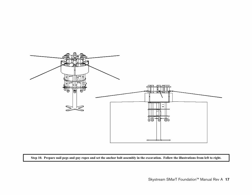
Step 10. Prepare nail pegs and guy ropes and set the anchor bolt assembly in the excavation. Follow the illustrations from left to right.
SMarT_Foundation™ [Simple Modular Technology] SMarT 2_v2 March 12, 2008 © 2007–2008 by AnemErgonics, LLC. All rights reserved. Page 16 of 22
Skystream SMarT Foundation™ Manual Rev A 17

Instructions for Assembly and Installation of SMarT_Foundation™ Kits (U.S. Patent Pending) for the Skystream Wind Turbine
Step Instructions Notes10 Prepare nail pegs and guy ropes and set the anchor
bolt assembly and stanchion in the excavation.
1. Locate four points on the ground where the Guy Ropes (25) will be attached to the Nail Pegs (26). These will be used to secure the an-chor bolt assembly. To keep the work area clear, locate the Nail Pegs 7 to 8 feet (2.1 to 2.4 m) from the centerline of the excavation. The two pairs should be aligned 90 degrees from each other.
2. Drive the Nail Pegs securely into the ground with hooks facing away from the excavation.
3. Tie the ends of the four Guy Ropes to four of the 1-1/2” ABS Template Spacers located 90 degrees apart (every other bolt).
4. Temporarily stow the guy ropes in the hollow top of the stanchion.
5. Check for proper assembly of the Anchor Rods, Rebar Hoops and 1” PVC electrical con-duit. The assembly should be quite rigid and the top nuts should be flush with the tops of the Anchor Rods.
6. Check the distance from the bottom of the ex-cavation to the top of grade. It must be as specified in the Drawings or the Anchor Rods will not be at the proper height for installation of the tower.
7. Carefully lift the assembly and lower it to the bottom of the excavation.
8. Locate the 1” PVC Elbow to facilitate the planned electrical conduit installation. Some manipulation may be required to avoid inter-ference with the Anchor Rods.
As noted in Step 4, the installer may already have decided to assemble the Kit in the excava-tion.
Caution: Look ahead to Step 11 and plan the alignment of nail pegs, anchor bolt assembly and PVC electrical conduit. These steps should be completed before placing the anchor bolt assembly in the excavation.
This step may require some loosening and retightening of the anchor bolt nuts.
Caution:• Use work gloves.• Plan and discuss Step 10.7 before proceeding. • Clear the excavation of any debris or loose soil. • Check the surrounding area and remove tripping hazards. • Lift the assembly by the anchor rods and not by the anchor bolt templates or rebar
hoops. This step requires at least two people. • If the bottom of the excavation is muddy or soft in the center – where the stanchion
will rest – the assembly may sink below the desired level. If this is likely, set the stanchion on a solid surface (such as a paving block) to reduce the soil pressure.
SMarT_Foundation™ [Simple Modular Technology] SMarT 2_v2 March 12, 2008 © 2007–2008 by AnemErgonics, LLC. All rights reserved. Page 17 of 22
18 Skystream SMarT Foundation™ Manual Rev A

Instructions for Assembly and Installation of SMarT_Foundation™ Kits (U.S. Patent Pending) for the Skystream Wind Turbine
56
Photo by Libby Oliver, Flagstaff, AZ
Step 11. Level and secure the anchor bolt assembly. Nail Pegs and Guy Ropes are used to stabilize and level the assembly. Here, the installer chose to add wood frames to locate the Cylindrical Concrete Form relative to the overall assembly. The Locater Brackets provided in the Kit serve this purpose, so that the wood frames shown above are unnecessary. Note also the use of a “barrel form” to deal with particularly loose soils. Instead of such a “barrel form” the installer could have chosen simply to pour more concrete. This is an individual choice.
SMarT_Foundation™ [Simple Modular Technology] SMarT 2_v2 March 12, 2008 © 2007–2008 by AnemErgonics, LLC. All rights reserved. Page 18 of 22 Skystream SMarT Foundation™ Manual Rev A 19

Instructions for Assembly and Installation of SMarT_Foundation™ Kits (U.S. Patent Pending) for the Skystream Wind Turbine
Step Instructions Notes11 Level and secure the anchor bolt assembly.
1. Check that the stanchion is resting in the center of the excavation.
2. Hold the assembly so that the top anchor bolt template is level.
3. Check that the lower surfaces of the lower An-chor Rod Nuts are 2 to 3 inches (51 to 76 mm) above the desired final earth grade.
4. Check that the Guy Ropes align with the Nail Pegs.
5. Attach the free ends of the Guy Ropes (with slides) to the hooks on the Nail Pegs.
6. Place a level atop two opposing Anchor Rods having Guy Ropes attached. Adjust the Guy Ropes until the assembly is level and held firmly.
7. Repeat Step 11.6 for the other two Anchor Rods with Guy Ropes attached.
8. Insert a 1” PVC electrical conduit of appropri-ate length (not supplied) into the bell end of the 1” PVC Elbow. Cement this joint to pre-vent moisture intrusion.
The lower surfaces of the Anchor Rod Nuts should be slightly above the top of the Cylindri-cal Concrete Form, which will also be the top surface of the concrete.
The top surface of the Anchor Rod Nuts should be flush with the tops of the Anchor Rods. That way, the Anchor Rods are leveled along with the nuts.
Caution: Check that the PVC electrical conduit is in an acceptable location. Make sure it is protected against infiltration of debris and that it extends beyond the foundation perime-ter for easy access when completing the electrical installation.
SMarT_Foundation™ [Simple Modular Technology] SMarT 2_v2 March 12, 2008 © 2007–2008 by AnemErgonics, LLC. All rights reserved. Page 19 of 22
20 Skystream SMarT Foundation™ Manual Rev A

Instructions for Assembly and Installation of SMarT_Foundation™ Kits (U.S. Patent Pending) for the Skystream Wind Turbine
Photo by Libby Oliver, Flagstaff, AZ
Photo by Libby Oliver, Flagstaff, AZ
Photo by Libby Oliver, Flagstaff, AZ
Photo by Libby Oliver, Flagstaff, AZ
Placing the Concrete
Pour the concrete slowly at several places around the foundation. Consolidate it with appropriate tools. Take care to prevent ex-cessive weight on any of the parts and to minimize movement of the anchor bolt as-sembly. Make a final check of alignment and level.
Step 12. Place and finish the concrete.
SMarT_Foundation™ [Simple Modular Technology] SMarT 2_v2 March 12, 2008 © 2007–2008 by AnemErgonics, LLC. All rights reserved. Page 20 of 22 Skystream SMarT Foundation™ Manual Rev A 21

Instructions for Assembly and Installation of SMarT_Foundation™ Kits (U.S. Patent Pending) for the Skystream Wind Turbine
Step Instructions Notes12 Place and finish the concrete.
1. Check that the tops of the Anchor Rods and the top surface of the Cylindrical Con-crete Form are level. Adjust if necessary.
2. Check the height of the Cylindrical Con-crete Form. Its top edge should be slightly below the bottom surface of the Anchor Rod Nuts.
3. Pour concrete to approximately 6 inches (152 mm) below the final earth grade. The slab should be at least 3 feet (0.91 m) thick.
4. Use a trowel to slope concrete away from the base of the Cylindrical Concrete Form to promote drainage toward the foundation perimeter.
5. Trowel-finish all concrete surfaces. 6. Use an edging tool to smooth the concrete
at the perimeter of the Cylindrical Con-crete Form.
7. After the concrete sets, remove the tem-plates and forms.
8. Backfill the excavation with native soil and compact it. Gravel or other landscap-ing materials may be used to fill the annu-lus around the stub pier. Slope the soil to-ward the foundation perimeter for drain-age. If this area is to be re-vegetated, ap-propriate soil amendments should be added.
Caution: Concrete placement should be performed by qualified, responsible individuals. Consult the turbine manufacturer and/or qualified professionals regarding lightning pro-tection and electrical grounding requirements.
Suggestions:• Safety is first! Identify the work area as a safety hazard and control access to it. • Prevent the excavation from freezing – use heaters or thermal blankets if necessary. • Prevent water from accumulating at the bottom of the excavation. • Keep the excavation clean and free from debris. • Check the condition of the excavation in preparation for concrete placement. • Check that the work area is clear, being especially careful about tripping hazards. • Have all tools and equipment readily available. • Recheck the anchor bolt height relative to the planned earth grade (Step 11.3). • Recheck that the anchor bolt assembly is level (Steps 11.6 and 11.7). • Make sure the concrete mix is fluid enough to fill potential voids. • Consolidate the concrete around the rebar and anchor bolt assembly. Note the
Drawings regarding vibration of concrete during construction. • Pour the concrete slowly from several locations around the excavation. Check that
the anchor bolt assembly remains in its intended position and is plumb. • Check that the PVC electrical conduit remains in its intended position. • Use hand tools to place and consolidate concrete within the cylindrical concrete
form.• Protect the concrete from sun, wind, hail, heavy rain and freezing for at least one
week after pouring. Use appropriate curing compounds or keep the concrete cov-ered and moist.
• Allow the concrete to cure for 24 hours before removing templates and forms. • Clean the anchor rods with a wire brush and appropriate solvent. • The tower and turbine must not be installed and erected – and design loads must
not be applied – until the 28-day concrete strength has been achieved as noted in the Drawings.
SMarT_Foundation™ [Simple Modular Technology] SMarT 2_v2 March 12, 2008 © 2007–2008 by AnemErgonics, LLC. All rights reserved. Page 21 of 22
22 Skystream SMarT Foundation™ Manual Rev A

rglov
er@tep
group
.net T
O OBTAIN
SEALED DRAW
INGS
Skystream SMarT Foundation™ Manual Rev A 23
FOR ILLUSTRATIO
N ONLY
– NOT FOR CONSTRUCTION
DRAWINGS AND INSTRUCTIONS ARE SUPPLIED W
ITH FOUNDATION KITS
CONTACT TOWER ENGINEERING PROFESSIONALS rg
O OBTAIN SEALED DRAWINGS

rglov
er@tep
group
.net T
O OBTAIN
SEALED DRAW
INGS
24 Skystream SMarT Foundation™ Manual Rev A
FOR ILLUSTRATIO
N ONLY
– NOT FOR CONSTRUCTION
DRAWINGS AND INSTRUCTIONS ARE SUPPLIED W
ITH FOUNDATION KITS
CONTACT TOWER ENGINEERING PROFESSIONALS rg
O OBTAIN SEALED DRAWINGS

rglov
er@tep
group
.net T
O OBTAIN
SEALED DRAW
INGS
Skystream SMarT Foundation™ Manual Rev A 25
FOR ILLUSTRATIO
N ONLY
– NOT FOR CONSTRUCTION
DRAWINGS AND INSTRUCTIONS ARE SUPPLIED W
ITH FOUNDATION KITS
CONTACT TOWER ENGINEERING PROFESSIONALS rg
O OBTAIN SEALED DRAWINGS

rglov
er@tep
group
.net T
O OBTAIN
SEALED DRAW
INGS
26 Skystream SMarT Foundation™ Manual Rev A
FOR ILLUSTRATIO
N ONLY
– NOT FOR CONSTRUCTION
DRAWINGS AND INSTRUCTIONS ARE SUPPLIED W
ITH FOUNDATION KITS
CONTACT TOWER ENGINEERING PROFESSIONALS rg
O OBTAIN SEALED DRAWINGS

rglov
er@tep
group
.net T
O OBTAIN
SEALED DRAW
INGS
Skystream SMarT Foundation™ Manual Rev A 27
FOR ILLUSTRATIO
N ONLY
– NOT FOR CONSTRUCTION
DRAWINGS AND INSTRUCTIONS ARE SUPPLIED W
ITH FOUNDATION KITS
CONTACT TOWER ENGINEERING PROFESSIONALS rg
O OBTAIN SEALED DRAWINGS

rglov
er@tep
group
.net T
O OBTAIN
SEALED DRAW
INGS
28 Skystream SMarT Foundation™ Manual Rev A
FOR ILLUSTRATIO
N ONLY
– NOT FOR CONSTRUCTION
DRAWINGS AND INSTRUCTIONS ARE SUPPLIED W
ITH FOUNDATION KITS
CONTACT TOWER ENGINEERING PROFESSIONALS rg
O OBTAIN SEALED DRAWINGS

rglov
er@tep
group
.net T
O OBTAIN
SEALED DRAW
INGS
Skystream SMarT Foundation™ Manual Rev A 29
FOR ILLUSTRATIO
N ONLY
– NOT FOR CONSTRUCTION
DRAWINGS AND INSTRUCTIONS ARE SUPPLIED W
ITH FOUNDATION KITS
CONTACT TOWER ENGINEERING PROFESSIONALS rg
O OBTAIN SEALED DRAWINGS


Southwest Windpower, Inc.1801 West Route 66Flagstaff, Arizona 86001Phone: 928.779.9463Fax: 928.779.1485www.skystreamenergy.com


![Rainbow Heart - artecy.com · 7777777 777777777 7777777777777 ooooooo 77777 7777777 7777777777777 oooooo]]]]] ddd ddd ddd ddd ddd ™™™™™™™™™™™ ™™™™™™™™™™™™™™™™™](https://static.fdocuments.us/doc/165x107/5f4a4ec8ec2fea16bc048a6a/rainbow-heart-7777777-777777777-7777777777777-ooooooo-77777-7777777-7777777777777.jpg)
