SMART CHARGING CONTROLLER - maxem.io · NAME 1 DRAWN LINEAR: CHK'D APPV'D MFG Q.A ANGULAR: FINISH:...
28
English - Installation manual Maxem 5
Transcript of SMART CHARGING CONTROLLER - maxem.io · NAME 1 DRAWN LINEAR: CHK'D APPV'D MFG Q.A ANGULAR: FINISH:...
S M A R T C H A R G I N G C O N T R O L L E R
English - Installation manual
Maxem 5

2
Safety warnings
• Onlytobeinstalledbyacertifiedelectrician.
• Completelyfollowtheinstructionsgiven.
• Use this device only for the purpose it is designed for, as described in this
manual.
• Maxemworksonlyafteronlinecommissioningbytheinstaller.
• FailuretofollowtheabovewarningscanleadtoanincorrectMaxeminstallation.
This can lead to over current on the grid connection, damage to installations
andchargingstations,electricshocksorfire.
Cohere is not responsible for the installation of Maxem and for any damage arising from not following the installationmanual correctly.Nor fordamage resulting from typographicalerrorsormisinterpretationsoftextorimages.
Tip Warning
Safety Information
Symbols in this document
Liability
Installation manual for Maxem Home
Publication date: 1 April 2018
See for the most latest information on
www.maxem.io
3
EN
All information in this document is the copyright and intellectual property of Cohere Energy SolutionsB.V.Materialinthisdocumentmaynotbemodified,reproducedorcopied,inpartorinwhole,withouttheexplicitwrittenconsentofCohereEnergySolutionsB.V.Additionalinformationisavailableuponrequest.
MaxemisaregisteredtrademarkofCohereEnergySolutionsB.V.
S M A R T C H A R G I N G C O N T R O L L E RC H A R G E S M A R T E R
©2018COHEREENERGYSOLUTIONSB.V.
Product symbols statements
Installandusethisproductonlyaftercarefulreadingofthemanual.
Thisproductisdoubleinsulated.
Indooruseonly.
Productcontainselectronics.Donotthrowitinthehouseholdwaste.
ThisproductisdesignedforovervoltagecategoryIII.
This product meets all the requirements set by the EU for
productsafety.
English

4
Index
What is Maxem? 29
Productspecifications 30
What do I need for the installation? 32
Installation steps
01 - Mounting of Maxem 34
02 - Connecting current transformers
Option2.1-Connecting current transformers on the grid connection 36
Option2.2-Connecting current transformers on the solar panels 36
03-ConnectingMIDkWh-meters 38
04 - Connecting charging station
Option4.1-ConnectingTesla Wall Connector 40
Option4.2-ConnectingKEBAcharging station 42
Option4.3-ConnectingICU charging station 44
05 - Commissioning by installer 45
ECDeclarationofConformity 70

5
ENWhat is Maxem?
From the meter cabinet, Maxem measures the energy use in the house and the energy
generation of solar panels. Based on this information, itmanages the charging station,
batteryorheatpumpsmartly.Thus, ithelpstheusertomakeeasierandcheaperuseof
sustainableenergy.
Maxem intelligently manages the charging
speed based on home energy use and solar
production, preventing over current on the
grid connection.
Charging station
Today you can monitor the energy use of
your heat pump. In the near future Maxem
manages the power of your heat pump or
e-boiler in order to store solar energy in hot
water.
Heat pump or e-boiler
Maxem optimizes power consumption on
the main grid connection to prevent over
current. This makes it unnecessary to get an
expensive grid upgrade.
Grid
Maxem measures the energy production of
your solar panels. Soon available: let
Maxem manage your charger on the basis
of solar production. This way you use 100%
of your own solar energy.
Solar panels
Battery
Future vision: through intelligent
measuring and management Maxem
makes sure that all solar power is stored in
the home battery. This way you use all your
solar energy locally.

6
01-Voorbereidingenvooraf
Content of the box
MIDkWh-meterextension
Maxem including mounting plate 6x split core current transformer
RS485 cable
NetworkcablePower cable
4x Screws 3x20 1x Phoenix connector
Productspecifications
2x Tie-wrap
SETOK
1 2 3
MIDkWh-meter
DefinitionsLEDindicators
On/off
Internet
Dataconnection
Current measurement
Charging station
1x Phoenix connector

7
EN
P1 port
Ethernet port to charging station
Ethernet port to Internet Router
230Vpowersupply
Current transformers solar panels
Multi functional USB port
Current transformers grid connection
RS485 port 1
RS485 port 2
Definitionsinput/outputports
Specifications
Dimensions 184mm(L)x167mm(W)x55mm(H)
Weight 700g
Working temperature 10°C to 35°C
Storage temperature 0°C to 60°C
Maximal humidity 80%
Protection class II (double insulated)
Seal IP20
Working height 0 to 2,000 m
EMC EN61326-1(2013),EN61000-3-2,61000-3-3
Safety EN61010-1(2010),EN61010-2-30(2010)
Immunity EN61326-1(2013)
Overvoltage category 300V/CATIII
Input power 110-240V.50/60Hz.Maximum2,75W
Power coils Up to 50A
REVISION
TITLE:
A4DWG NO.
SCALE:1:2 SHEET 1 OF 2WEIGHT:
A A
B B
C C
D D
E E
F F
4
4
3
3
2
2
1
DATESIGNATURE
DO NOT SCALE DRAWING
MATERIAL:
NAME
1
DRAWN
LINEAR:
CHK'D
APPV'D
MFG
Q.A
ANGULAR:
FINISH:
TOLERANCES:EDGES
UNLESS OTHERWISE SPECIFIED:DIMENSIONS ARE IN MILLIMETERSSURFACE FINISH:
DEBURR AND BREAK SHARP
Maxem5-R4

8
• Acorrectcircuitbreakerorearthleakagecircuitbreakerwithproperfusingvalue. See
p.33todeterminefusing.
• Schukosocketsfor230VpowersupplyMaxem(ifnotalreadyavailable).
• UTP(CAT5orCAT6)datacableforconnectingchargingstationtoMaxem.
• RJ45(8P8C)connectorsforethernetconnectedchargingstations(ICU/Keba).
• CableendsleevesforUTPcores(onlyforTeslaWallConnector).
• Internetconnectedsmartphone,tabletorcomputer.
Required materials
01-VoorbereidingenvoorafWhat do I need for the installation?
Wired Internet access
With Maxem compatible charging stations
Compatibility may change over time. See the website www.maxem.io for the current overview of compatible charging stations.
Tesla Wall Connector ICUEVeminiKEBAP20/P30 ICUEVe
The followingnetwork settings are required.Don’t be alarmedby the jargon, these are
normalnetworksettings.Incorporatenetworkssomeoptionscanbeblocked:
• MaxemhastoreceiveanIPaddressviaDHCP.
• This IP address may not be in the following range: 10.50.0.0/16, 10.51.0.0/16, and
192.168.25.1/24.
• Incaseofafirewalloutgoingtraffichastobeallowedonthefollowingports:80,443,
1194t/m1200and9090.

9
EN
Fusing charging station
Maxemisacontrolsystemthatregulatestheloadofthechargingstation.Maxemmakes
surethatthereislessloadonthechargingstationwhenthereismoreloadonthehouse.
This reduces thediversity factor. The charging station can thereforebe fused toa value
higherthannormal,butnothigherthanthethresholdvalueofthemaingridconnection.
FormoreinformationonthissubjectinrelationtotheNEN1010,seetheMaxemwebsite.
Power supply Charging station capacity Maximal fusing, charging station
3-phase 25A 3-phase 32A 3-phase 25A
3-phase 25A 3-phase 16A 3-phase 16A
3-phase 35A 3-phase 32A 3-phase 32A
1-phase 25A 1-phase 32A 1-phase 25A
1-phase 40A 1-phase 32A 1-phase 32A
Current transformers of kWh-meters
Maxem is standard supplied with current transformers with which the main grid connection
andsolarproductioncanbemeasured.Formoreaccuratemeasurementsitisalsopossible
to use MID certified kWh-meters. The kWh-meters Maxem works with can be ordered
separately.
There are situations when a kWh-meter is always required:
• Measurement of a Tesla Wall Connector
• Measurement of a heat pump

10
01-Voorbereidingenvooraf01 - Mounting of Maxem
MountMaxemonaclean,moisture-freewall.Use thesuppliedmountingplateand
screwsforthis.TakeintoaccountsufficientspacearoundtheMaxem.
Wiring at the bottom
70mm
20mm
20mm20mm
A.

11
EN
Connect Maxem with the supplied network cable to the modem or router connected
totheInternet.
Maxemhas tobeconnected toa230Vwall socket.Prepare thisalreadybutdonot
powerMaxemyet.
C.
B.
230Vconnection
REVISION
TITLE:
A4DWG NO.
SCALE:1:2 SHEET 1 OF 2WEIGHT:
A A
B B
C C
D D
E E
F F
4
4
3
3
2
2
1
DATESIGNATURE
DO NOT SCALE DRAWING
MATERIAL:
NAME
1
DRAWN
LINEAR:
CHK'D
APPV'D
MFG
Q.A
ANGULAR:
FINISH:
TOLERANCES:EDGES
UNLESS OTHERWISE SPECIFIED:DIMENSIONS ARE IN MILLIMETERSSURFACE FINISH:
DEBURR AND BREAK SHARP
Maxem5-R4
Ethernet port to Internet Router
REVISION
TITLE:
A4DWG NO.
SCALE:1:2 SHEET 1 OF 2WEIGHT:
A A
B B
C C
D D
E E
F F
4
4
3
3
2
2
1
DATESIGNATURE
DO NOT SCALE DRAWING
MATERIAL:
NAME
1
DRAWN
LINEAR:
CHK'D
APPV'D
MFG
Q.A
ANGULAR:
FINISH:
TOLERANCES:EDGES
UNLESS OTHERWISE SPECIFIED:DIMENSIONS ARE IN MILLIMETERSSURFACE FINISH:
DEBURR AND BREAK SHARP
Maxem5-R4

12
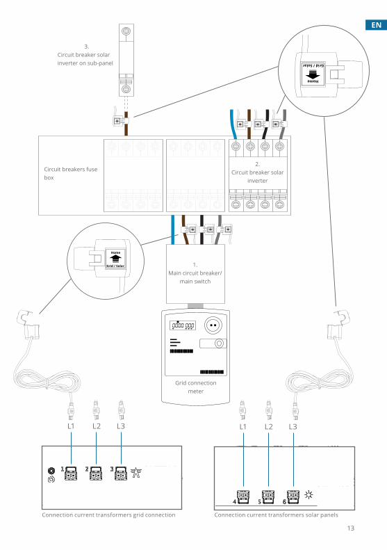
02 - Connecting current transformers
Option2.2-ConnectingCT’sonsolarpanels
Click the supplied current transformer around the L1 phase wire of the main power
supply, after the main circuit breaker/main switch, such that the entire grid connection
ismeasured(seefig.1)
Connectthecurrenttransformercabletoport1ofMaxem.
Turnoffthemaincircuitbreakerofswitchofthefusebox.Andopenthefusebox.
RepeatthesestepsforL2andL3incaseofa3-phasegridconnection.Phase2is
connectedonport2.Phase3isconnectedonport3.
Makesurethecurrenttransformersareconnectedintherightdirection.
A.
B.
D.
E.
Option2.1-ConnectingCT’sonthegridconnection
Click the supplied current transformer around the L1 wire of the circuit breaker
tothesolarinverter(seefig.2).Nootherloadsmaybeconnectedtothiscircuit
breaker.
Turnoffthemainpowersupplyterminalofthefusebox.A.
B.
C.
Connect the current transformer to the corresponding circuit breaker in the fuse
box.Nootherloadsmaybeconnectedtothiscircuitbreaker.
Makesurethecurrenttransformersareconnectedintherightdirection.D.
B.
Connect the current transformer to port 4 ofMaxem. Repeat these steps for
L2andL3; connectL2 toport5, connectL3 toport6.Makesureeachcurrent
transformerofeachphaseisconnectedtotheassociatedportonMaxem.
C.
Connect the current transformer to the corresponding port on Maxem. For
instance;.port6,whensolarisconnectedtoL3onthegridconnection.Orport
5forL2.
C.
For 3-phase solar energy (see fig. 2)
For 1-phase solar energy on a sub-panel (see fig. 3)
13
EN
Home
Grid / Solar
Home
Grid / Solar
Home
Grid / Solar
Home
Grid / Solar
Home
Grid / Solar
Home
Grid / SolarHome
Grid / Solar
REVISION
TITLE:
A4DWG NO.
SCALE:1:2 SHEET 1 OF 2WEIGHT:
A A
B B
C C
D D
E E
F F
4
4
3
3
2
2
1
DATESIGNATURE
DO NOT SCALE DRAWING
MATERIAL:
NAME
1
DRAWN
LINEAR:
CHK'D
APPV'D
MFG
Q.A
ANGULAR:
FINISH:
TOLERANCES:EDGES
UNLESS OTHERWISE SPECIFIED:DIMENSIONS ARE IN MILLIMETERSSURFACE FINISH:
DEBURR AND BREAK SHARP
Maxem5-R4
L1 L2 L3
Grid / Solar
Home
Grid / Solar
Home
REVISION
TITLE:
A4DWG NO.
SCALE:1:2 SHEET 1 OF 2WEIGHT:
A A
B B
C C
D D
E E
F F
4
4
3
3
2
2
1
DATESIGNATURE
DO NOT SCALE DRAWING
MATERIAL:
NAME
1
DRAWN
LINEAR:
CHK'D
APPV'D
MFG
Q.A
ANGULAR:
FINISH:
TOLERANCES:EDGES
UNLESS OTHERWISE SPECIFIED:DIMENSIONS ARE IN MILLIMETERSSURFACE FINISH:
DEBURR AND BREAK SHARP
Maxem5-R4
L1 L2 L3
1.Main circuit breaker/
main switch
Gridconnectionmeter
Circuit breakers fuse box
3.Circuit breaker solar inverter on sub-panel
2.Circuit breaker solar
inverter
Connection current transformers grid connection Connection current transformers solar panels
14
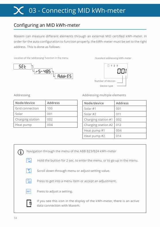
03-ConnectingMIDkWh-meter
MaxemcanmeasuredifferentelementsthroughanexternalMIDcertifiedkWh-meter. In
orderfortheautoconfigurationtofunctionproperly,thekWh-metermustbesettotheright
address.Thisisdoneasfollows:
Node/device Address
Solar #1 001
Solar #2 011
Charging station #1 002
Charging station #2 012
Heat pump #1 004
Heat pump #2 014
Locationofthe‘addressing’functioninthemenu
SETOK
1 2 3
Addressing multiple elements
Numberofdevices
Devicetype
Standard addressing kWh-meter
Node/device Address
Gridconnection 100
Solar 001
Charging station 002
Heat pump 004
Addressing
ConfiguringanMIDkWh-meter
Holdthebuttonfor2sec.toenterthemenu,ortogoupinthemenu.
Scrolldownthroughmenuoradjustsettingvalue.
Presstogetintoamenuitemoracceptanadjustment.
Presstoadjustasetting.
NavigationthroughthemenuoftheABBB23/B24kWh-meter
If you see this icon in the display of the kWh-meter, there is an active dataconnectionwithMaxem.

15
EN
PlacethekWh-meteronaDIN-railinthefusebox.
ConnectinganMIDkWh-meter
ConnectthegreenPhoenixconnectortoportRS1onMaxem.
Connect behind the main circuit breaker so that it measures the output of the
completegridconnection.NoticethatthiskWh-meterisfedfromthetopend.
SettheaddressofthekWh-metertocorrespondingnode.
SETOK
1 2 3
Connection RS485 cable on kWh-meter
A.
B.
D.
E.
RS1 port for MIDkWh-meter
REVISION
TITLE:
A4DWG NO.
SCALE:1:2 SHEET 1 OF 2WEIGHT:
A A
B B
C C
D D
E E
F F
4
4
3
3
2
2
1
DATESIGNATURE
DO NOT SCALE DRAWING
MATERIAL:
NAME
1
DRAWN
LINEAR:
CHK'D
APPV'D
MFG
Q.A
ANGULAR:
FINISH:
TOLERANCES:EDGES
UNLESS OTHERWISE SPECIFIED:DIMENSIONS ARE IN MILLIMETERSSURFACE FINISH:
DEBURR AND BREAK SHARP
Maxem5-R4
Connection RS485 cable on Phoenix connector
C B A
Connect a 1-phase solar installation which supplies L3 of the main grid connection also to L3 of the kWh-meter. The same goes for L2.
Connect the RS485 cable to the kWh-
meter and the supplied green Phoenix
connector as follows:
kWh-
meter
Wire
color
Phoenix-
connector
A Brown 1
B White 2
C Green 3
C.
213

16
04 - Connecting the charging station
Option4.1-ConnectingaTeslaWallConnector
Install a circuit breaker and/or earth leakage circuit breaker for each
chargingstationatthemaximalpoweravailable.Seep.33.
Follow the installation instructions of the charging station. These
instructions can be found in the installation manual of the charging
station.
A.
B.
Set the Wall Connector to Slave mode
by placing the rotary switch in F
position.
On the Maxem side connect the
supplied green Phoenix connector
to the data cable. 2wires need to be
connected:
• Connect wire 1 (orange-white) to
port2.
• Connectwire2(orange)toport1.
Connect the green Phoenix connector
toportRS2ofMaxem.
ConnectthedatacabletotheINportof
the clamp block of the Wall Connector:
• Connect wire 1 (orange-white) to
D+
• Connectwire2(oranje)toD-
Place a suitable UTP (CAT5 or CAT6) of theWall Connector toMaxem. (To prevent
electromagnetic interference at the RS485 connection, it is recommended to use FTP
CAT6cableatdistancemorethan25m.Max:50m).
C.
F.
G.
E.
D.
Draaischakelaar
F
D+ D- D+ D-In Uit
RS2 poort voor laadstation
REVISION
TITLE:
A4DWG NO.
SCALE:1:2 SHEET 1 OF 2WEIGHT:
A A
B B
C C
D D
E E
F F
4
4
3
3
2
2
1
DATESIGNATURE
DO NOT SCALE DRAWING
MATERIAL:
NAME
1
DRAWN
LINEAR:
CHK'D
APPV'D
MFG
Q.A
ANGULAR:
FINISH:
TOLERANCES:EDGES
UNLESS OTHERWISE SPECIFIED:DIMENSIONS ARE IN MILLIMETERSSURFACE FINISH:
DEBURR AND BREAK SHARP
Maxem5-R4
1 2 3

17
EN
TopLEDisgreen;theWallConnectorisreadytocharge.
Correct LED
indication
See installation manual Tesla Wall Connector for more information.
Top LED is green, center LED blinks red 4x; theWall
Connector is set to Slave, but is not communicating
withMaxem..
Incorrect LED
indication

18
REVISION
TITLE:
A4DWG NO.
SCALE:1:2 SHEET 1 OF 2WEIGHT:
A A
B B
C C
D D
E E
F F
4
4
3
3
2
2
1
DATESIGNATURE
DO NOT SCALE DRAWING
MATERIAL:
NAME
1
DRAWN
LINEAR:
CHK'D
APPV'D
MFG
Q.A
ANGULAR:
FINISH:
TOLERANCES:EDGES
UNLESS OTHERWISE SPECIFIED:DIMENSIONS ARE IN MILLIMETERSSURFACE FINISH:
DEBURR AND BREAK SHARP
Maxem5-R4
Option4.2-ConnectingaKEBAchargingstation
Install a circuit breaker and/or earth leakage circuit breaker at the
maximalpoweravailable. Seep.33.
Follow the installation instructions of the charging station. These
instructions can be found in the installation manual of the charging
station.
Place a suitable UTP (CAT5 or CAT6) cable from the charging station to Maxem and
clenchRJ45connectorsonbothsides.
Connect the UTP cable to the Ethernet
port of the charging station and the
ETHportofMaxem.
It is advisable to test the network cable with the help of a cable tester.
DSW1-Power(paragraphabove)DSW2-Addressing(paragraphbelow)
DataactivityonETHportMaxem
DataactivityonETHportKebaP20orP30
UTP cable with RJ45 connectors
A.
B.
C.
D.
ETH port for charging station
REVISION
TITLE:
A4DWG NO.
SCALE:1:2 SHEET 1 OF 2WEIGHT:
A A
B B
C C
D D
E E
F F
4
4
3
3
2
2
1
DATESIGNATURE
DO NOT SCALE DRAWING
MATERIAL:
NAME
1
DRAWN
LINEAR:
CHK'D
APPV'D
MFG
Q.A
ANGULAR:
FINISH:
TOLERANCES:EDGES
UNLESS OTHERWISE SPECIFIED:DIMENSIONS ARE IN MILLIMETERSSURFACE FINISH:
DEBURR AND BREAK SHARP
Maxem5-R4

19
EN
PutDSW1.3ONtoactivatesmartcharging.
SettheDIPswitchesofDSW1onthemaximalavailablepower.Andleavetherestofthe
DIPswitchesonOFF.
E.
F.
Example 10A
DSW1.6OFF
DSW1.7OFF
DSW1.8OFF
10A
13A
16A
Maximal current strength
20A
25A
32A
SettingsonDSW11 of 3-phase
SeeinstallationmanualKEBAP20/P30formoreinformation
SwitchofftheKebaP20/P30(theDIPswitchsettingsonlybecomeactiveafterareset
ofthechargingstation).
G.

20
Option4.3-ConnectinganICUchargingstation
Connect the UTP cable to the Ethernet
port of the charging station and the
ETHportofMaxem.
It is possible to update the charging station firmware. This can be done via ICU Connect, as soon as the charging station is online. ICU Alfen can assist you with this.
It is advisable to test the network cable with the help of a cable tester.
Data activity onETH port ICU
UTP cable with RJ45 connectors
D.
REVISION
TITLE:
A4DWG NO.
SCALE:1:2 SHEET 1 OF 2WEIGHT:
A A
B B
C C
D D
E E
F F
4
4
3
3
2
2
1
DATESIGNATURE
DO NOT SCALE DRAWING
MATERIAL:
NAME
1
DRAWN
LINEAR:
CHK'D
APPV'D
MFG
Q.A
ANGULAR:
FINISH:
TOLERANCES:EDGES
UNLESS OTHERWISE SPECIFIED:DIMENSIONS ARE IN MILLIMETERSSURFACE FINISH:
DEBURR AND BREAK SHARP
Maxem5-R4
Install a circuit breaker and/or earth leakage circuit breaker for each
charging station at the maximal power available.Seep.33.
Follow the installation instructions of the charging station. These
instructions can be found in the installation manual of the charging
station.
Place a suitable UTP (CAT5 or CAT6) cable from the charging station to Maxem and
clenchRJ45connectorsonbothsides.
A.
B.
C.
DataactivityonETHport Maxem
ETH poort voor laadstation
REVISION
TITLE:
A4DWG NO.
SCALE:1:2 SHEET 1 OF 2WEIGHT:
A A
B B
C C
D D
E E
F F
4
4
3
3
2
2
1
DATESIGNATURE
DO NOT SCALE DRAWING
MATERIAL:
NAME
1
DRAWN
LINEAR:
CHK'D
APPV'D
MFG
Q.A
ANGULAR:
FINISH:
TOLERANCES:EDGES
UNLESS OTHERWISE SPECIFIED:DIMENSIONS ARE IN MILLIMETERSSURFACE FINISH:
DEBURR AND BREAK SHARP
Maxem5-R4
21
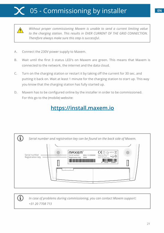
EN05 - Commissioning by installer
Without proper commissioning Maxem is unable to send a current limiting value to the charging station. This results in OVER CURRENT OF THE GRID CONNECTION. Therefore always make sure this step is successful.
Turnonthechargingstationorrestartitbytakingoffthecurrentfor30sec.and
puttingitbackon.Waitatleast1minuteforthechargingstationtostartup.Thisway
youknowthatthechargingstationhasfullystartedup.
Connectthe230VpowersupplytoMaxem.A.
B.
Maxemhastobeconfiguredonlinebytheinstallerinordertobecommissioned.
For this go to the (mobile) website:
https://install.maxem.io
D.
In case of problems during commissioning, you can contact Maxem support:
+31 20 7708 713
Input: 110 - 240V ~ 0,5A 50/60Hz Max 2,75W
Serial number:
CAT III
Made in The Netherlands.Registration key:
8 719326 026800
MX4-1-H-0000000000
Serial numberRegistration key
Serial number and registration key can be found on the back side of Maxem.
Wait until the first 3 status LED’s onMaxem are green. Thismeans thatMaxem is
connectedtothenetwork,theinternetandthedatacloud.
C.

22
LEDindicatorsonMaxem
LED icon
Icon meaning
LED indication Meaning What to do
On/off
Light is green Maxemisactive. -
Blinks orange Maxemisstartingup. -
Blinks red Maxemisresetting. -
Off Maxemisoff. Checkpowersupply.
Internet
Light is greenInternet connection is present.
-
Light is orangeNetworkconnectionpresent, but no Internet connection.
Check for an active Internet connection on the network cabletoMaxem.Thiscanbedone by connecting a laptop tothiscable.
Light is redNonetworkandnoInternetconnection.
Check Internet cable and/or Internetrouter.
Dataconnection
Light is greenConnection to Maxem server isactive.
-
Light is orangeSomething is wrong with the Maxemcloud.
Call the Maxem support telephonenumber.
Light is red
Something is wrong with the local network and Maxem is unable to connect to the cloud.
Check the requirements for the Internet connection on page 32 (also see FAQ on the Maxemwebsite).
Current measure-ment
Light is green All measurements are ok -
Blinks orange MaxemisnotconfiguredTheconfigurationifnotfinished.Gotohttps://install.maxem.io.
Light is redOne or more found measurementsarenotok.
Check the connection of the current transformers or the connection and configurationofthekWh-meter(s).
Charging station
Light is greenCommunication with chargingstationisok.
-
Blinks orange Maxemisnotconfiguredyet.Theconfigurationifnotfinished.Gotohttps://install.maxem.io.
Light is redNocommunicationwithchargingstation.
Check the data cable to the chargingstation.Checkwhether the charging station requiresasoftwareupdate.

23
EN

24

25
EN

26
We,
CohereEnergySolutionsB.V.WillemdeZwijgerlaan3501055RDAmsterdam,Nederland
followingtheprovisionofthefollowingECDirectives:• 2006/95/ECTheLowVoltageDirective• 2004/108/EECTheElectromagneticCompatibilityDirective
Herebydeclarethattheproduct:MaxemEnergyManager4.0isinconformitywiththe applicable requirements of the following documents:
Emissions• EN61326-1(2013)• EN61000-3-2(2006)+A1(2009)+A2(2009)• EN61000-3-3(2008)
Immunity• EN61326-1(2013)
Safety• EN61010-1(2010),• EN61010-2-030(2010)• EN61010-2-023
Signee Date Place Signature
Jan Willem HeinenCEO
1 August 2016 Amsterdam
TroubleshootingECDeclarationofConformity

27
DE

Maxem is a product of Cohere Energy SolutionsWillemdeZwijgerlaan350|1055RD|Amsterdam|TheNetherlands
[email protected]|www.maxem.io