
Smart Antenna for Broadband Mobile Satellite Communications at Ka-Band
21
Smart Antenna Terminal for Broadband Mobile Satellite Communications at Ka-Band A .Dreher (2) , A. Geise (1) , R. Gieron (4) , S. Holzwarth (4) , C. Hunscher (3) , A. F. Jacob (1) , K. Kuhlmann (1) , O. Litschke (4) , D. Lohmann (4) , H. Pawlak (1) , W. Simon (4) , L. C. Stange (OHB GmbH), M. Thiel (2) (1) (2) (3) (4)
Transcript of Smart Antenna for Broadband Mobile Satellite Communications at Ka-Band
Smart Antenna Terminal forBroadband Mobile Satellite Communications
at Ka-BandA .Dreher(2), A. Geise(1), R. Gieron(4), S. Holzwarth(4), C. Hunscher(3),
A. F. Jacob(1), K. Kuhlmann(1), O. Litschke(4), D. Lohmann(4), H. Pawlak(1), W. Simon(4), L. C. Stange (OHB GmbH), M. Thiel(2)
(1) (2) (3) (4)

1
AeronauticsDays 2006
Project
Overview
A. Dreher, DLR
Introduction – background and visionSystem conceptSANTANA phase 1 - results• 1st demonstrator – Tx• 1st demonstrator – Rx
SANTANA phase 2 - improvements• Architecture• RF-to-antenna interconnect• Rx antenna element• Tx antenna LTCC multilayer structure
Outlook - mobile field test• Ground field tests• Airborne field fests
Overview
2
AeronauticsDays 2006
Project
Overview
A. Dreher, DLR
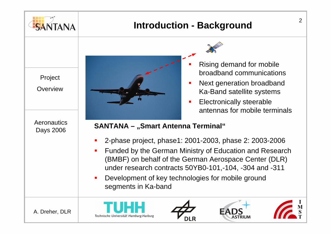
Introduction - Background
SANTANA – „Smart Antenna Terminal“
2-phase project, phase1: 2001-2003, phase 2: 2003-2006Funded by the German Ministry of Education and Research (BMBF) on behalf of the German Aerospace Center (DLR) under research contracts 50YB0-101,-104, -304 and -311Development of key technologies for mobile groundsegments in Ka-band
Rising demand for mobile broadband communicationsNext generation broadbandKa-Band satellite systemsElectronically steerableantennas for mobile terminals
3
AeronauticsDays 2006
Project
Overview
A. Dreher, DLR
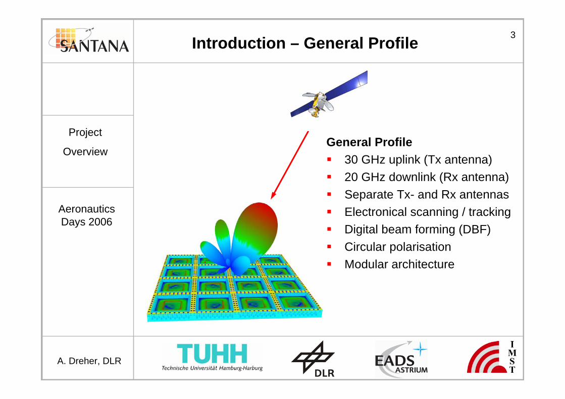
General Profile30 GHz uplink (Tx antenna)20 GHz downlink (Rx antenna)Separate Tx- and Rx antennasElectronical scanning / trackingDigital beam forming (DBF)Circular polarisationModular architecture
Introduction – General Profile
4
AeronauticsDays 2006
Project
Overview
A. Dreher, DLR
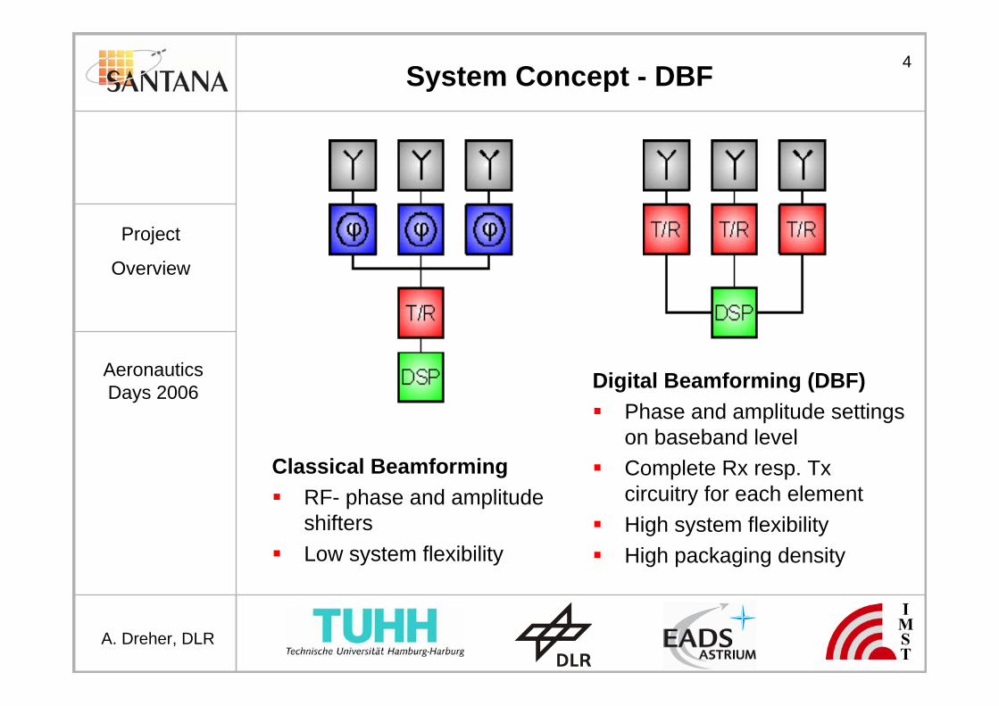
System Concept - DBF
Classical BeamformingRF- phase and amplitudeshiftersLow system flexibility
Digital Beamforming (DBF)Phase and amplitude settingson baseband levelComplete Rx resp. Txcircuitry for each elementHigh system flexibilityHigh packaging density

5
AeronauticsDays 2006
Project
Overview
A. Dreher, DLR
System Concept - Modular Architecture
Modular ConceptModules consistingof 4x4 elementsCustomized array sizesfor different applicationsEasy maintenanceof modulesBase plate providesclock and LO generation,power supply and cooling
6
AeronauticsDays 2006
Project
Overview
A. Dreher, DLR
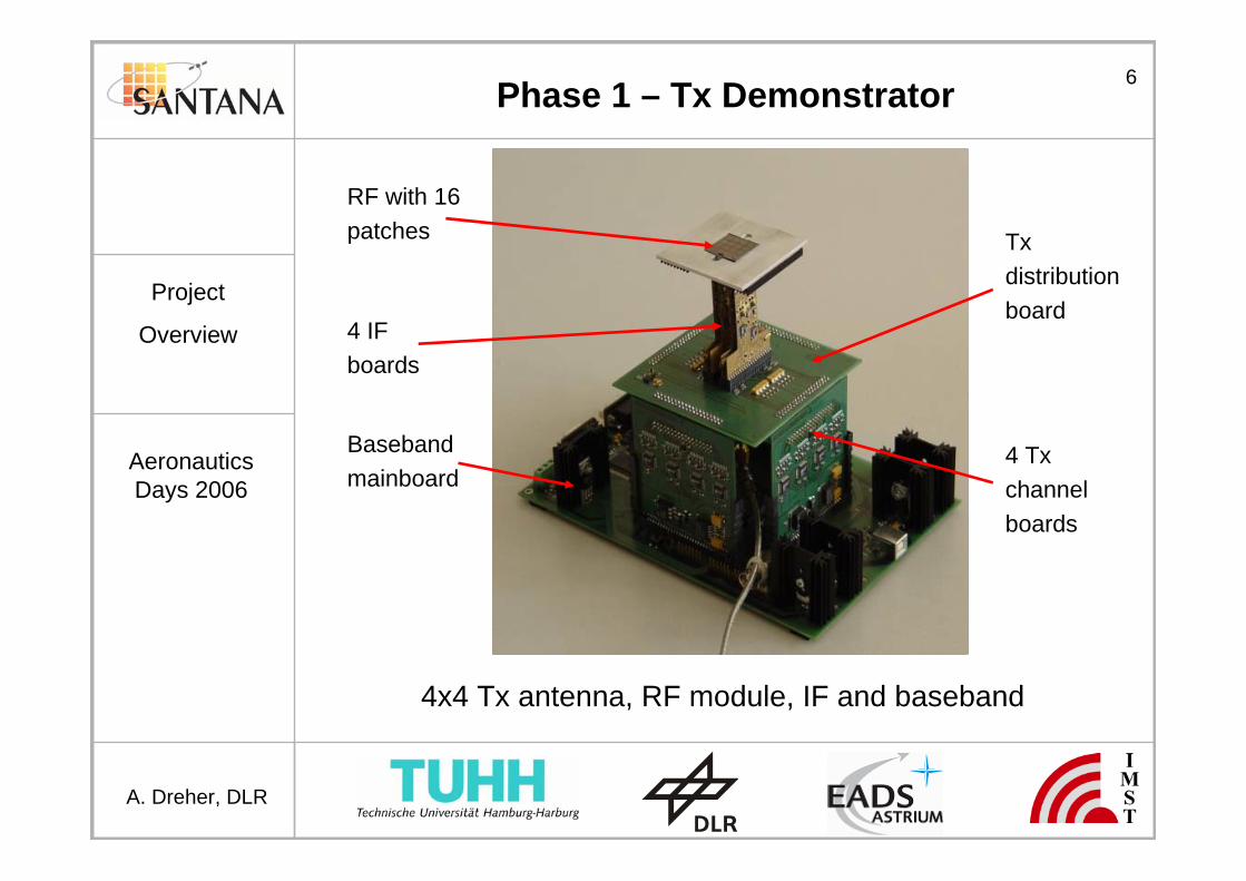
Phase 1 – Tx Demonstrator
RF with 16patches
4 IF boards
Basebandmainboard
4 Txchannelboards
Txdistributionboard
4x4 Tx antenna, RF module, IF and baseband
7
AeronauticsDays 2006
Project
Overview
A. Dreher, DLR
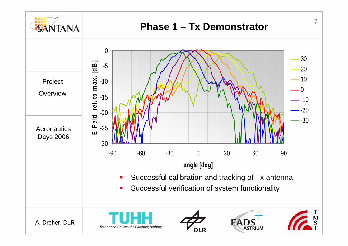
Phase 1 – Tx Demonstrator
-30
-25
-20
-15
-10
-5
0
-90 -60 -30 0 30 60 90
angle [deg]
E-Fe
ld r
el. t
o m
ax. [
dB] 30
20100-10-20-30
Successful calibration and tracking of Tx antennaSuccessful verification of system functionality

8
AeronauticsDays 2006
Project
Overview
A. Dreher, DLR
Phase 1- Rx Demonstrator
RF with16 patches
4 IF boards
Basebandmainboard
Rx distributionboard
4 Rx channelboards
4x4 Rx antenna, RF module, IF and baseband
9
AeronauticsDays 2006
Project
Overview
A. Dreher, DLR
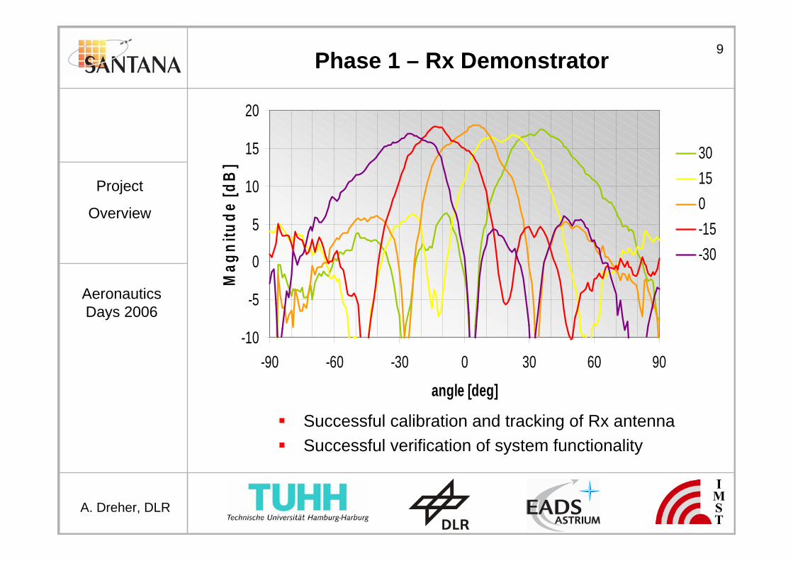
Phase 1 – Rx Demonstrator
-10
-5
0
5
10
15
20
-90 -60 -30 0 30 60 90
angle [deg]
Mag
nitu
de [d
B] 30
150-15-30
Successful calibration and tracking of Rx antennaSuccessful verification of system functionality
10
AeronauticsDays 2006
Project
Overview
A. Dreher, DLR
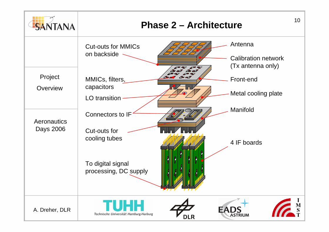
Phase 2 – Architecture
Antenna
Front-end
Metal cooling plate
Manifold
4 IF boards
MMICs, filters,capacitors
LO transition
Cut-outs forcooling tubes
To digital signalprocessing, DC supply
Calibration network(Tx antenna only)
Cut-outs for MMICson backside
Connectors to IF
11
AeronauticsDays 2006
Project
Overview
A. Dreher, DLR
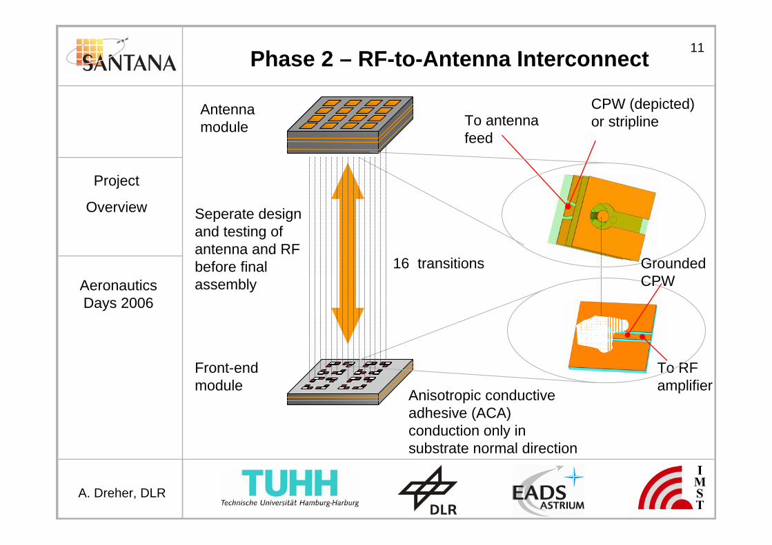
Phase 2 – RF-to-Antenna Interconnect
To RFamplifier
To antennafeed
Anisotropic conductiveadhesive (ACA) conduction only insubstrate normal direction
Antennamodule
Front-endmodule
16 transitions GroundedCPW
CPW (depicted)or stripline
Seperate designand testing ofantenna and RFbefore finalassembly

12
AeronauticsDays 2006
Project
Overview
A. Dreher, DLR
Phase 2 – Rx Antenna Element
New RF to antenna interconnectionModification of former Tx antennadesignAperture-coupled patch antennaRadiating element and interconnectdesigned and measured separately
3D view
Detail 4x4 antenna arrayFront Back

13
AeronauticsDays 2006
Project
Overview
A. Dreher, DLR
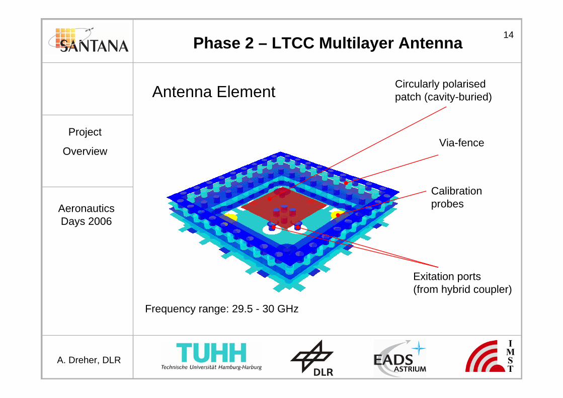
Phase 2 – LTCC Multilayer Antenna
11 LTCClayers Patch
Calibrationnetwork
RF interface
Hybrid ringcoupler
Probe
Cavity
14
AeronauticsDays 2006
Project
Overview
A. Dreher, DLR
Antenna Element Circularly polarisedpatch (cavity-buried)
Calibrationprobes
Via-fence
Exitation ports(from hybrid coupler)
Phase 2 – LTCC Multilayer Antenna
Frequency range: 29.5 - 30 GHz

15
AeronauticsDays 2006
Project
Overview
A. Dreher, DLR
Calibration Network
2 probesper element
Cell size1 element
To internalcalibrationreceiver
In-phaseaddition
Symmetricalnetwork
Phase 2 – LTCC Multilayer Antenna

16
AeronauticsDays 2006
Project
Overview
A. Dreher, DLR
Phase 2 – Tx Demonstrator
RF with 64patches
16 IF boards
Basebandmainboard
Tx channelboards
Tx distributionboard
Powerboard
8x8 Tx antenna, RF modules, IF and baseband boards

17
AeronauticsDays 2006
Project
Overview
A. Dreher, DLR
Phase 2 - Rx Demonstrator
RF with 64patches
16 IF boards
Basebandmainboard
Rx channelboards
Rx distributionboard
Powerboard
8x8 Rx antenna, RF modules, IF and baseband boards
18
AeronauticsDays 2006
Project
Overview
A. Dreher, DLR
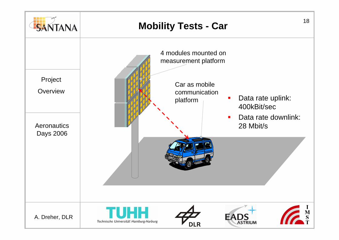
Mobility Tests - Car
Car as mobilecommunicationplatform
4 modules mounted on measurement platform
Data rate uplink:400kBit/secData rate downlink:28 Mbit/s

19
AeronauticsDays 2006
Project
Overview
A. Dreher, DLR
Mobility Tests - Airplane
4 modules mounted on ground
Airplane as mobilecommunicationplatform
Altitude: 3kmVelocity: 70m/sMax. angular velocity: 1.3 deg/sData rate uplink: 400kBit/secData rate downlink: 28 Mbit/s

20
AeronauticsDays 2006
Project
Overview
A. Dreher, DLR
Conclusion
SANTANA phase 1• Verification of basic system functionality
SANTANA phase 2• Improved architecture and RF-to-antenna interconnect• New Rx antenna element design• Innovative LTCC Tx antenna multilayer design including
calibration network• Incorporation of new manufacturing technologies• Compatibility with industrial processes• Field tests to verify mobile data links


![Design of Ionofree Micro Strip Quad Helix Antenna for ... · antenna, bifilar helices antenna, microstrip antenna, quadrafilar helix antenna. ... Helical antenna [1],[2] is broadband](https://static.fdocuments.us/doc/165x107/5b9506e809d3f2ea5c8b5a04/design-of-ionofree-micro-strip-quad-helix-antenna-for-antenna-bifilar-helices.jpg)

