SMALL WASTEWATER (SEPTIC SYSTEM) APPLICATION FREMONT...
12
SMALL WASTEWATER (SEPTIC SYSTEM) APPLICATION FREMONT COUNTY, WYOMING Step 1: Before any work begins complete and submit the application packet with the correct permit fee : Permit fees: $250.00 for replacement systems,$275.00 for new systems and $300.00 for non-conventional systems, As–built ,$1,000.00 , Additional inspections, $50.00,payable to: Fremont County Planning Department 450 North 2 nd Street, Room 360 Lander, WY 82520 Please allow 2 WEEKS to process the application. Incomplete applications will delay processing. if you have any questions or need assistance contact the Planning Department at 332-1077 or 1-800-967-2297, ext. 1830 (outside Lander or Riverton), or fax to 332-1177. Marcel Lopez, Small Wastewater Specialist (332-1830 or 330-4010) [email protected] Step 2: To insure compliance with State and Fremont County Regulations: plan the layout for your home site, with the following minimum distance requirements in mind: From To Septic Tank To Leach field Wells (including neighboring wells) 50’ 100’ Open waterway (including streams, lakes or ditches) 50’ 50’ Potable water line 25’ 25’ Building foundation (without foundation drain) 5’ 10’ Building foundation (with foundation drain) 5’ 25’ Break in slope greater than 15% 15’ 15’ Property line 10’ 10’ Septic tank n/a 10’ Be sure to choose a site where the bottom of the leach field is at least 4 ft. from the high groundwater level and at least 4 ft. from any bedrock or impermeable soil layer. This will require a backhoe cut. If this is not possible you must notify the Planning Department. Step 3: Run percolation tests in the area of the proposed leach field rounding up to the nearest whole number. Instructions and forms are on pages 5-7 of the application. Step 4: Prior to construction, you must make an appointment for a site evaluation. During the site eval- uation we will provide specific information as to the size and configuration of the leach field, if the percola- tion test has been done. Step 5: INSPECTION Prior to backfilling, the system must be inspected by a representative of the Plan- ning Department. A 48-hour advance notice would be appreciated if possible. IMPORTANT REMINDER: Before undertaking any excavation, contractors and landowners have a duty to call to locate any utilities buried beneath worksites. Public utilities have established a nationwide network. This is a free public service & it’s the law. In Wyoming this service is called One Call of Wyoming: (800) 849-2476 or 811. 1
Transcript of SMALL WASTEWATER (SEPTIC SYSTEM) APPLICATION FREMONT...

SMALL WASTEWATER (SEPTIC SYSTEM) APPLICATION
FREMONT COUNTY, WYOMING
Step 1: Before any work begins complete and submit the application packet with the correct permit fee : Permit fees: $250.00 for replacement systems,$275.00 for new systems and $300.00 for non-conventional systems, As–built ,$1,000.00 , Additional inspections, $50.00,payable to:
Fremont County Planning Department 450 North 2nd Street, Room 360
Lander, WY 82520
Please allow 2 WEEKS to process the application. Incomplete applications will delay processing. if you have any questions or need assistance contact the Planning Department at 332-1077 or
1-800-967-2297, ext. 1830 (outside Lander or Riverton), or fax to 332-1177.
Marcel Lopez, Small Wastewater Specialist (332-1830 or 330-4010) [email protected]
Step 2: To insure compliance with State and Fremont County Regulations: plan the layout for your home site, with the following minimum distance requirements in mind:
From To Septic Tank To Leach field Wells (including neighboring wells) 50’ 100’ Open waterway (including streams, lakes or ditches) 50’ 50’ Potable water line 25’ 25’ Building foundation (without foundation drain) 5’ 10’ Building foundation (with foundation drain) 5’ 25’ Break in slope greater than 15% 15’ 15’ Property line 10’ 10’ Septic tank n/a 10’
Be sure to choose a site where the bottom of the leach field is at least 4 ft. from the high groundwater level and at least 4 ft. from any bedrock or impermeable soil layer. This will require a backhoe cut. If this is not possible you must notify the Planning Department.
Step 3: Run percolation tests in the area of the proposed leach field rounding up to the nearest whole number. Instructions and forms are on pages 5-7 of the application.
Step 4: Prior to construction, you must make an appointment for a site evaluation. During the site eval-uation we will provide specific information as to the size and configuration of the leach field, if the percola-tion test has been done.
Step 5: INSPECTION Prior to backfilling, the system must be inspected by a representative of the Plan-ning Department. A 48-hour advance notice would be appreciated if possible.
IMPORTANT REMINDER: Before undertaking any excavation, contractors and landowners have a duty to call to locate any utilities buried beneath worksites. Public utilities have established a nationwide network. This is a free public service & it’s the law. In Wyoming this service is called One Call of Wyoming: (800) 849-2476 or 811.
1

NOTICE TO ALL DEVELOPERS, BUILDERS
& PROPERTY OWNERS
Fremont County would like to make you aware of more exacting definitions of wetlands result-
ing from delineation methods by the U.S. Army Crops of Engineers. If you intend to do any
construction, dredging, or placing of fill material in waterways or wetlands, contact the Corps
of Engineers regarding required approvals under Section 404 of the Clean Water Act. This Act
applies rivers, streams, lakes, intermittent streams, isolated water bodies, wetlands or suspected
wetlands.
Fremont County does not administer the 404 program, nor requires permits under the 404 pro-
gram as part of compliance with Fremont County regulations. It is the responsibility of the
property owner to apply for all federal permits.
If you have any questions or concerns please contact:
U.S ARMY CORPS OF ENGINEERS
2232 Del Range Blvd., Suite 210
Cheyenne, WY 82009
Phone: (307) 772-2300
Fax: (307) 772-2920
Example
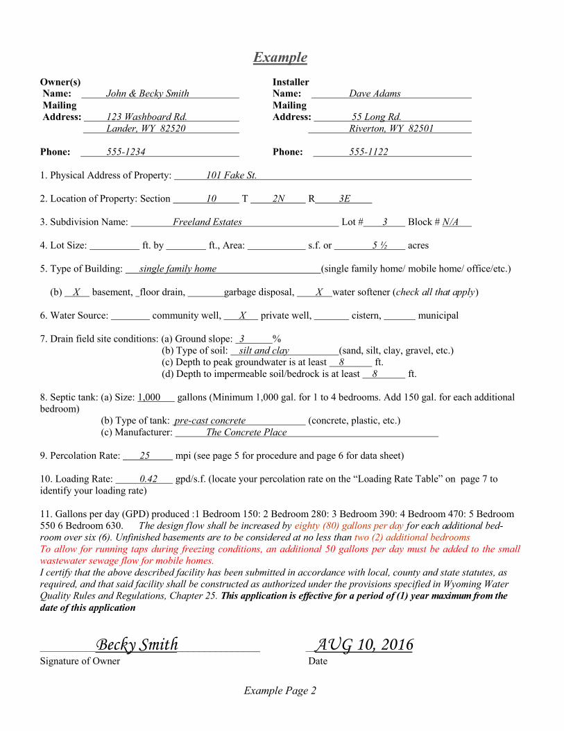
Owner(s) Installer
Name: John & Becky Smith Name: Dave Adams
Mailing Mailing Address: 123 Washboard Rd. Address: 55 Long Rd.
Lander, WY 82520 Riverton, WY 82501
Phone: 555-1234 Phone: 555-1122
1. Physical Address of Property: 101 Fake St.
2. Location of Property: Section 10 T 2N R 3E
3. Subdivision Name: Freeland Estates Lot # 3 Block # N/A
4. Lot Size: ft. by ft., Area: s.f. or 5 ½ acres
5. Type of Building: single family home (single family home/ mobile home/ office/etc.)
(b) X basement, floor drain, garbage disposal, X water softener (check all that apply)
6. Water Source: community well, X private well, cistern, municipal
7. Drain field site conditions: (a) Ground slope: 3 %
(b) Type of soil: silt and clay (sand, silt, clay, gravel, etc.)
(c) Depth to peak groundwater is at least 8 ft.
(d) Depth to impermeable soil/bedrock is at least 8 ft.
8. Septic tank: (a) Size: 1,000 gallons (Minimum 1,000 gal. for 1 to 4 bedrooms. Add 150 gal. for each additional
bedroom)
(b) Type of tank: pre-cast concrete (concrete, plastic, etc.)
(c) Manufacturer: The Concrete Place
9. Percolation Rate: 25 mpi (see page 5 for procedure and page 6 for data sheet)
10. Loading Rate: 0.42 gpd/s.f. (locate your percolation rate on the “Loading Rate Table” on page 7 to
identify your loading rate)
11. Gallons per day (GPD) produced :1 Bedroom 150: 2 Bedroom 280: 3 Bedroom 390: 4 Bedroom 470: 5 Bedroom
550 6 Bedroom 630. The design flow shall be increased by eighty (80) gallons per day for each additional bed-
room over six (6). Unfinished basements are to be considered at no less than two (2) additional bedrooms
To allow for running taps during freezing conditions, an additional 50 gallons per day must be added to the small
wastewater sewage flow for mobile homes.
I certify that the above described facility has been submitted in accordance with local, county and state statutes, as
required, and that said facility shall be constructed as authorized under the provisions specified in Wyoming Water
Quality Rules and Regulations, Chapter 25. This application is effective for a period of (1) year maximum from the
date of this application
____________Becky Smith_______________ __AUG 10, 2016
Signature of Owner Date
Example Page 2

Owner(s) Installer
Name: Name:
Mailing Mailing
Address: Address:
Phone: Phone:
1. Physical Address of Property: ____________________________________________
2. Location of Property: Section_____ T________ R________
3. Subdivision Name: ___________________________________ Lot #____ Block#____
4. Lot Size: ___________ft. by ___________ft., Area:____________ft² or ___________acres
5. (a) Type of Building: ______________________ (single family home/ mobile home/ office/ etc.)
(b) ____ basement, ____ floor drain, ____garbage disposal, ____ water softener (check all that apply)
6. Water Source: ____ community well, ____ private well, ____ cistern, ____ municipal
7. Drain field site conditions: (a) Ground slope: ________%
(b) Type of soil: ________________(sand, silt, clay, gravel, etc.)
(c) Depth to peak groundwater is at least _____ ft.
(d) Depth to impermeable soil/bedrock is at least _____ft.
8. Septic tank: (a) Size: _____gallons (Minimum 1,000 gal. for 1 to 4 bedrooms. Add 150 gal. for each additional bedroom)
(b) Manufacturer: _________________________________________
9. Percolation Rate: __________ mpi (See page 5 for procedure and page 6 for data sheet)
10. Loading Rate: _________ gpd/s.f. (Locate your percolation rate on the “Loading Rate Table” on page 7)
11. Gallons per day (GPD) produced indicate one:1 Bedroom 150: 2 Bedroom 280: 3 Bedroom 390: 4 Bedroom
470: 5 Bedroom 550 6 Bedroom 630. The design flow shall be increased by eighty (80) gallons per day for each
additional bedroom over six (6). Unfinished basements are to be considered at no less than two (2) additional bed-
rooms
To allow for running taps during freezing conditions, an additional 50 gallons per day must be added to the small
wastewater sewage flow for mobile homes.
I certify that the above described facility has been submitted in accordance with local, county and state stat-
utes, as required, and that said facility shall be constructed as authorized under the provisions specified in
Wyoming Water Quality Rules and Regulations, Chapter 25. This application is effective for a period of (1)
year maximum from the date of this application
________________________________________ __________________
Signature of Owner Date
Page 2

Example
12. Drain field size calculations:
Wastewater volume = __630__gpd
÷ = 1,500 ft² Loading Rate = __0.42__gpd/s.f.
13. Drain field layout:
(a) Type of system: (check one)
_____ Rock and perforated pipe Trench
_____ Rock and perforated pipe Bed
__X__Chamber Trench system
_____ Chamber Bed system
(b) Request the appropriate design sheet during the pre-construction site evaluation with the Planning
Department staff.
Construction Requirements
SEPTIC TANK
1. Tank design must comply with Wyoming DEQ standards.
2. The septic tank must contain baffles and/or “T’s” that extend into the middle third of the liquid depth.
A minimum 20” man way must be installed for each compartment of the tank. The riser from the access
opening shall terminate at a maximum of six (6) inches below the ground surface. Riser covers terminating
above grade shall have an approved locking device.
3. Tank must be set on top of compacted or undisturbed soil.
BUILDING SEWER
1. All solid pipe between the house and the tank and between the tank and field must have a minimum
slope of ¼” per foot (2%) for a 4” pipe.
2. The septic tank inlet and outlet pipes shall be 4” schedule 40 PVC and shall extend past the septic tank
excavation to undisturbed soil.
3. Cleanouts shall be provided at least every 100 ft. and up grade of any change in alignment greater than
22.5 degrees. A cleanout just outside the house is required, regardless of the distance to the tank.
LEACHFIELD
1. Pipe and Stone Systems-A minimum of 6” of washed stone under the pipe and a minimum of 2” of
washed stone over the pipe is required. The stone must be covered by filter cloth or 2” of straw before
backfilling. Do not use plastic sheeting or tar paper.
2. The bottom of all beds and trenches must be level.
3. A minimum of 12” of backfill is required to cover the field.
4. The field must be 15 ft. from the break in slope if the slope is steeper than 20%.
Example Page 3

12. Minimum square feet of infiltrative surface needed:
Wastewater volume = ______gpd
÷ = _____ ft²
Loading Rate = ______gpd/ft²
13. Drain field layout:
(a) Type of system: (check one)
_____ Rock and perforated pipe Trench
_____ Rock and perforated pipe Bed
_____ Chamber Trench system
_____ Chamber Bed system
(b) Request the appropriate design sheet during the pre-construction site evaluation with the Planning
Department staff.
Construction Requirements
SEPTIC TANK
1. Tank design must comply with Wyoming DEQ standards.
2. The septic tank must contain baffles and/or “T’s” that extend into the middle third of the liquid depth.
A minimum 20” man way must be installed for each compartment of the tank. The riser from the access
opening shall terminate at a maximum of six (6) inches below the ground surface. Riser covers terminating
above grade shall have an approved locking device.
3. Tank must be set on top of compacted or undisturbed soil.
BUILDING SEWER
1. All solid pipe between the house and the tank and between the tank and field must have a minimum
slope of ¼” per foot (2%) for a 4” pipe.
2. The septic tank inlet and outlet pipes shall be 4” schedule 40 PVC and shall extend past the septic tank
excavation to undisturbed soil.
3. Cleanouts shall be provided at least every 100 ft. and up grade of any change in alignment greater than
22.5 degrees. A cleanout just outside the house is required, regardless of the distance to the tank.
LEACHFIELD
1. Pipe and Stone Systems-A minimum of 6” of washed stone under the pipe and a minimum of 2” of
washed stone over the pipe is required. The stone must be covered by filter cloth or 2” of straw before
backfilling. Do not use plastic sheeting or tar paper.
2. The bottom of all beds and trenches must be level.
3. A minimum of 12” of backfill is required to cover the field.
4. The field must be 15 ft. from the break in slope if the slope is steeper than 20%.
For Office Use Only
Page 3

PL
AN
SH
EE
T
Mak
e a
dra
win
g o
f yo
ur
pro
per
ty,
incl
ud
ing:
1.
pro
per
ty l
ines
2.
all
buil
din
gs
3.
all
wel
ls w
ithin
20
0’
4. dri
nkin
g w
ater
lin
es
5.
str
eam
s, d
itch
es,
surf
ace
bo
die
s o
f w
ater
6.
bre
aks
in s
lop
e gre
ater
th
an 1
5%
7.
sep
tic
tan
k
8.
lea
ch f
ield
9.
a N
OR
TH
AR
RO
W
10.
the
road
yo
u w
ill
use
to
acc
ess
the
ho
use
11.
the
dri
vew
ay
12.
an
are
a fo
r fu
ture
in
stal
lati
on
of
a
RE
PL
AC
EM
EN
T L
EA
CH
FIE
LD
Show
th
e re
lati
ve
dis
tan
ces
of
thes
e fe
ature
s. S
ee
table
bel
ow
fo
r m
inim
um
dis
tan
ce r
equ
irem
ents
.
Fro
m
T
o S
epti
c T
ank
T
o L
each
fie
ld
Wel
ls
5
0’
1
00
’
Open
wat
erw
ay 5
0’
5
0’
Pota
ble
wat
er l
ine
25
’
25
’
Bu
ildin
g f
oundat
ion
(w
ith
out
fndn
. d
rain
) 5
’
10
’
Buil
din
g f
ou
ndat
ion
(w
ith
fnd
n.
dra
in)
5’
2
5’
Bre
ak i
n s
lop
e
15
’
15
’
Pro
per
ty l
ine
1
0’
1
0’
Sep
tic
tan
k
N
/A
1
0’
Rev
iew
ed b
y:
Dat
e of
Au
tho
riza
tion
:
Exa
mp
le P
lan
Exa
mple
Page
4
Or
a
Dis
trib
utio
n b
ox

PL
AN
SH
EE
T
Mak
e a
dra
win
g o
f yo
ur
pro
per
ty,
incl
ud
ing:
1. p
roper
ty l
ines
2. a
ll b
uil
din
gs
3. a
ll w
ells
wit
hin
20
0’
4.
dri
nkin
g w
ater
lin
es
5. s
trea
ms,
dit
ches
, su
rfac
e b
od
ies
of
wat
er
6. b
reak
s in
slo
pe
gre
ater
th
an 1
5%
7. s
epti
c ta
nk
8. l
each
fie
ld
9. a
NO
RT
H A
RR
OW
10.
the
road
yo
u w
ill
use
to
acc
ess
the
ho
use
11.
the
dri
vew
ay
12.
an
are
a fo
r fu
ture
in
stal
lati
on
of
a
RE
PL
AC
EM
EN
T L
EA
CH
FIE
LD
Sh
ow
th
e re
lati
ve
dis
tan
ces
of
thes
e fe
ature
s. S
ee
table
bel
ow
fo
r m
inim
um
dis
tan
ce r
equ
irem
ents
.
Fro
m
T
o S
epti
c T
ank
T
o L
each
fie
ld
Wel
ls
5
0’
1
00
’
Open
wat
erw
ay 5
0’
5
0’
Po
table
wat
er l
ine
25
’
25
’
Bu
ildin
g f
oundat
ion
(w
ith
out
fndn
. d
rain
) 5
’
10
’
Bu
ildin
g f
ou
ndat
ion
(w
ith
fnd
n.
dra
in)
5’
2
5’
Bre
ak i
n s
lop
e
15
’
15
’
Pro
per
ty l
ine
1
0’
1
0’
Sep
tic
tan
k
N
/A
1
0’
Rev
iew
ed b
y:
Dat
e of
Au
tho
riza
tion
:
Page
4
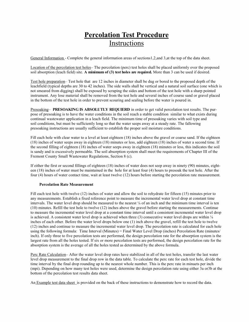
Percolation Test Procedure
Instructions
General Information - Complete the general information areas of sections1,2,and 3,at the top of the data sheet.
Location of the percolation test holes– The percolation (perc) test holes shall be placed uniformly over the proposed
soil absorption (leach field) site. A minimum of (3) test holes are required. More than 3 can be used if desired.
Test hole preparation– Test hole that are 12 inches in diameter shall be dug or bored to the proposed depth of the
leachfield (typical depths are 30 to 42 inches). The side walls shall be vertical and a natural soil surface (one which is
not smeared from digging) shall be exposed by scraping the sides and bottom of the test hole with a sharp pointed
instrument. Any lose material shall be removed from the test hole and several inches of course sand or gravel placed
in the bottom of the test hole in order to prevent scouring and sealing before the water is poured in.
Presoaking– PRESOAKING IS ABSOLUTLY REQUIERD in order to get valid percolation test results. The pur-
pose of presoaking is to have the water conditions in the soil reach a stable condition similar to what exists during
continual wastewater application in a leach field. The minimum time of presoaking varies with soil type and
soil conditions, but must be sufficiently long so that the water seeps away at a steady rate. The fallowing
presoaking instructions are usually sufficient to establish the proper soil moisture conditions.
Fill each hole with clear water to a level at least eighteen (18) inches above the gravel or coarse sand. If the eighteen
(18) inches of water seeps away in eighteen (18) minutes or less, add eighteen (18) inches of water a second time. If
the second filling of eighteen (18) inches of water seeps away in eighteen (18) minutes or less, this indicates the soil
is sandy and is excessively permeable. The soil absorption system shall meet the requirements of Chapter III of the
Fremont County Small Wastewater Regulations, Section 8 (c).
If either the first or second fillings of eighteen (18) inches of water does not seep away in ninety (90) minutes, eight-
een (18) inches of water must be maintained in the hole for at least four (4) hours to presoak the test hole. After the
four (4) hours of water contact time, wait at least twelve (12) hours before starting the percolation rate measurement.
Percolation Rate Measurement
Fill each test hole with twelve (12) inches of water and allow the soil to rehydrate for fifteen (15) minutes prior to
any measurements. Establish a fixed reference point to measure the incremental water level drop at constant time
intervals. The water level drop should be measured to the nearest ⅛ of an inch and the minimum time interval is ten
(10) minutes. Refill the test hole to twelve (12) inches above the gravel before starting the measurements. Continue
to measure the incremental water level drop at a constant time interval until a consistent incremental water level drop
is achieved. A consistent water level drop is achieved when three (3) consecutive water level drops are within ⅛
inches of each other. Before the water level drops below one (1) inch above the gravel, refill the test hole to twelve
(12) inches and continue to measure the incremental water level drop. The percolation rate is calculated for each hole
using the following formula: Time Interval (Minutes) = Final Water Level Drop (inches) Percolation Rate (minutes/
inch). If only three to five percolation tests are performed, the design percolation rate for the absorption system is the
largest rate from all the holes tested. If six or more percolation tests are performed, the design percolation rate for the
absorption system is the average of all the holes tested as determined by the above formula.
Perc Rate Calculation– After the water level drop rates have stabilized in all of the test holes, transfer the last water
level drop measurement to the final drop row in the data table. To calculate the perc rate for each test hole, divide the
time interval by the final drop rounding up to the nearest whole number. This is the perc rate in minuets per inch
(mpi). Depending on how many test holes were used, determine the design percolation rate using either 3a or3b at the
bottom of the percolation test results data sheet.
An Example test data sheet is provided on the back of these instructions to demonstrate how to record the data.

PERCOLATION TEST RESULTS
1. Performed by: Mike Plumber Test date(s): 6-23 & 6-24,99
Credentials or status of tester:________________________________
(Owner,Contractor,Installer,engineer,geologist,sanitarian,soil scientist, or other)
2. The time interval (ti) between water level measurements was:____minutes.
3. TEST DATA: The test holes were PRESOAKED for :__Hours,or X over -
night.
Test Hole # is _1_ _2_ _3_
Hole depth (inches)= 34” 38” 37”
Interval Elapsed Water Water Water
Number Time Level/Drop Level/
Drop Level/Drop
Start = 0min 17”
1 1/4 ←
1 10 18 1/4
1
2 20 19 1/4 ←
3/4
3 30 20
5/8
4 40 20 5/8
Re- fill ← 5 50 15
1/2
6 60 15 1/2
3/8
7 70 15 7/8
1/2
8 80 16 3/8
__________________________________________________________________
Final Drop
(NOT TOTAL) = 1/2 ___ ___
__________________________________________________________________
Perc Rate(mpi) is:
[ti/Final drop]=10/½= 20.0mpi ___ ___
A. If 6 or more holes were tested, the average perc rate was:NA mpi or
Water level drop
Between intervals
The actual water level below
The top of the test hole
Refill hole if needed and re-measure
Actual water level
Continue the test until 3 consecutive
“drops” are the same to within
1/8 inch total variation

PERCOLATION TEST RESULTS
1. Performed by: ___________ Test date(s): ________________
Credentials or status of tester:______________________________________
(Owner,Contractor,Installer,engineer,geologist,sanitarian,soil scientist, or other)
2. The time interval (ti) between water level measurements was:____minutes.
3. TEST DATA: The test holes were PRESOAKED
for:__Hours,or__overnight.
Test Hole # is ___ ___ ___
Hole depth (inches)=
Interval Elapsed Water Water Water
Number Time Level/Drop Level/Drop Level/Drop
Start = 0min ____ ____ ____
___ ___ ___
1 ___ ____ ____ ____
___ ___ ___
2 ___ ____ ____ ____
___ ___ ___
3 ___ ____ ____ ____
___ ___ ___
4 ___ ____ ____ ____
___ ___ ___
5 ___ ____ ____ ____
___ ___ ___
6 ___ ____ ____ ____
___ ___ ___
7 ___ ____ ____ ____
___ ___ ___
8 ___ ____ ____ ____
__________________________________________________________________
Final Drop
(NOT TOTAL) = ___ ___ ___
__________________________________________________________________
Perc Rate(mpi) is:
[ti/Final drop]= ___mpi ___ ___
A. If 6 or more holes were tested, the average perc rate was:____mpi or
B. If 3 to 5 holes were tested, the slowest perc rate (largest number) was:___mpi
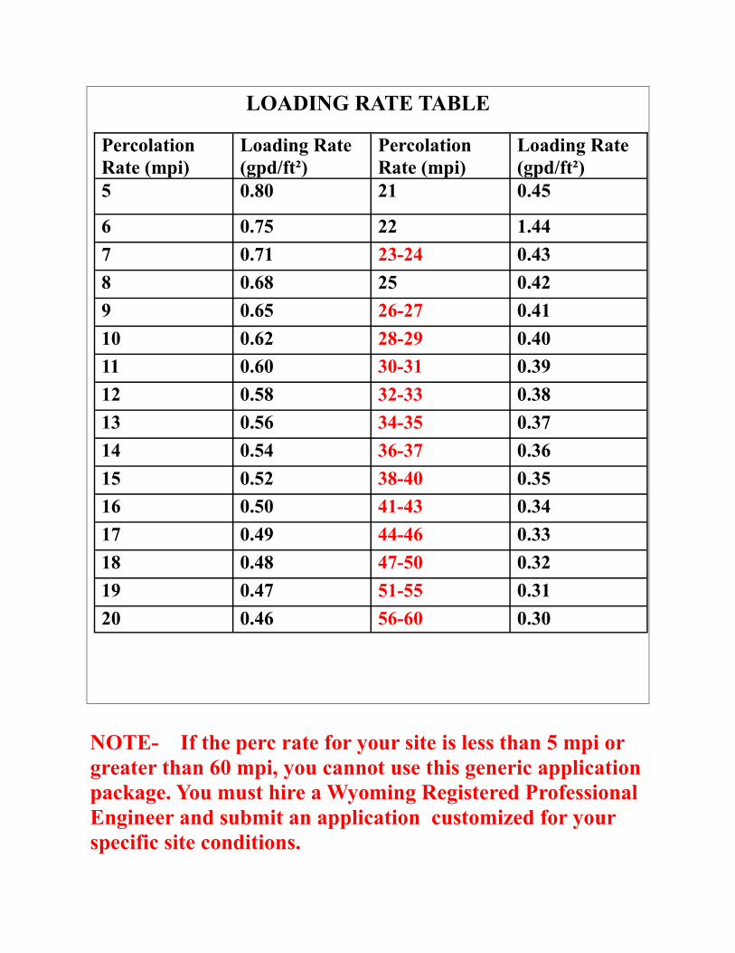
LOADING RATE TABLE
Percolation
Rate (mpi)
Loading Rate
(gpd/ft²)
Percolation
Rate (mpi)
Loading Rate
(gpd/ft²)
5 0.80 21 0.45
6 0.75 22 1.44
7 0.71 23-24 0.43
8 0.68 25 0.42
9 0.65 26-27 0.41
10 0.62 28-29 0.40
11 0.60 30-31 0.39
12 0.58 32-33 0.38
13 0.56 34-35 0.37
14 0.54 36-37 0.36
15 0.52 38-40 0.35
16 0.50 41-43 0.34
17 0.49 44-46 0.33
18 0.48 47-50 0.32
19 0.47 51-55 0.31
20 0.46 56-60 0.30
NOTE- If the perc rate for your site is less than 5 mpi or
greater than 60 mpi, you cannot use this generic application
package. You must hire a Wyoming Registered Professional
Engineer and submit an application customized for your
specific site conditions.