Small-Scale ORC Energy Recovery System for Wasted Heat: … · 2014-08-21 · velocity triangle. h....
34
SMALL-SCALE ORC ENERGY RECOVERY SYSTEM FOR WASTED HEAT: THERMODYNAMIC FEASIBILITY ANALYSIS AND PRELIMINARY EXPANDER DESIGN Roberto Capata, Claudia Toro Department of Mechanical and Aerospace Engineering, University of Rome “Sapienza”, Via Eudossiana 18, Rome, Italy
Transcript of Small-Scale ORC Energy Recovery System for Wasted Heat: … · 2014-08-21 · velocity triangle. h....

SMALL-SCALE ORC ENERGY RECOVERY SYSTEM FOR WASTED HEAT: THERMODYNAMIC FEASIBILITY ANALYSIS AND PRELIMINARY EXPANDER DESIGN
Roberto Capata, Claudia Toro Department of Mechanical and Aerospace Engineering,
University of Rome “Sapienza”, Via Eudossiana 18, Rome, Italy
Summary • Objectives of the Work • Organic fluids • Thermodynamic simulations of ORC cycle • ORC expander design
• Blade design • Structural analysis
• Results and Conclusions • Future developments
2

Objectives of the Work • Thermodynamic feasibility of an innovative Organic
Rankine Cycle (ORC) recovery system for automotive applications; • a small-scale ORC energy recovery system fed by the exhaust
gases of a diesel engine or GT device;
• Preliminary design of the expander dynamic turbine
• single-stage radial turbine
3
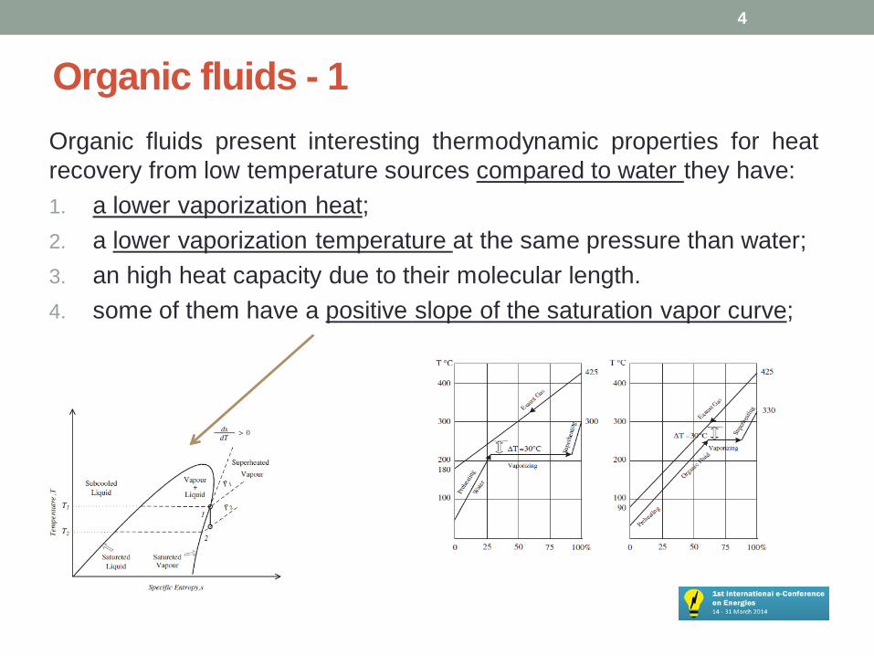
Organic fluids - 1 Organic fluids present interesting thermodynamic properties for heat recovery from low temperature sources compared to water they have: 1. a lower vaporization heat; 2. a lower vaporization temperature at the same pressure than water; 3. an high heat capacity due to their molecular length. 4. some of them have a positive slope of the saturation vapor curve;
4
Organic fluids - 2 • First three properties allow to use low temperature sources, the fourth
consents to have an expansion from a non-superheated vapor point without enter in the vapor dome.
• This aspect is fundamental, because is not necessary to superheat the fluid because at the end of the expansion the fluid is still in the vapor phase avoiding any problems in the expander, especially if it is a turbine.
• In an ORC design is the choice of the fluid based on the source; in practice, most used fluids are three:
1. R134a (1,1,1,2-Tetrafluoroethane) 2. R123 (2,2-Dichloro-1,1,1-trifluoroethane) 3. R245fa (1,1,1,3,3-Pentafluoropropane)
5
Organic fluids - 3 • In addition to the thermodynamically properties, the
organic fluids for ORC have to be secure for people and environment:
1. No flammable 2. No explosive 3. Non-toxic 4. Low Ozone Depletion Potential (ODP) 5. Low Global Warming Potential (GWP)
6
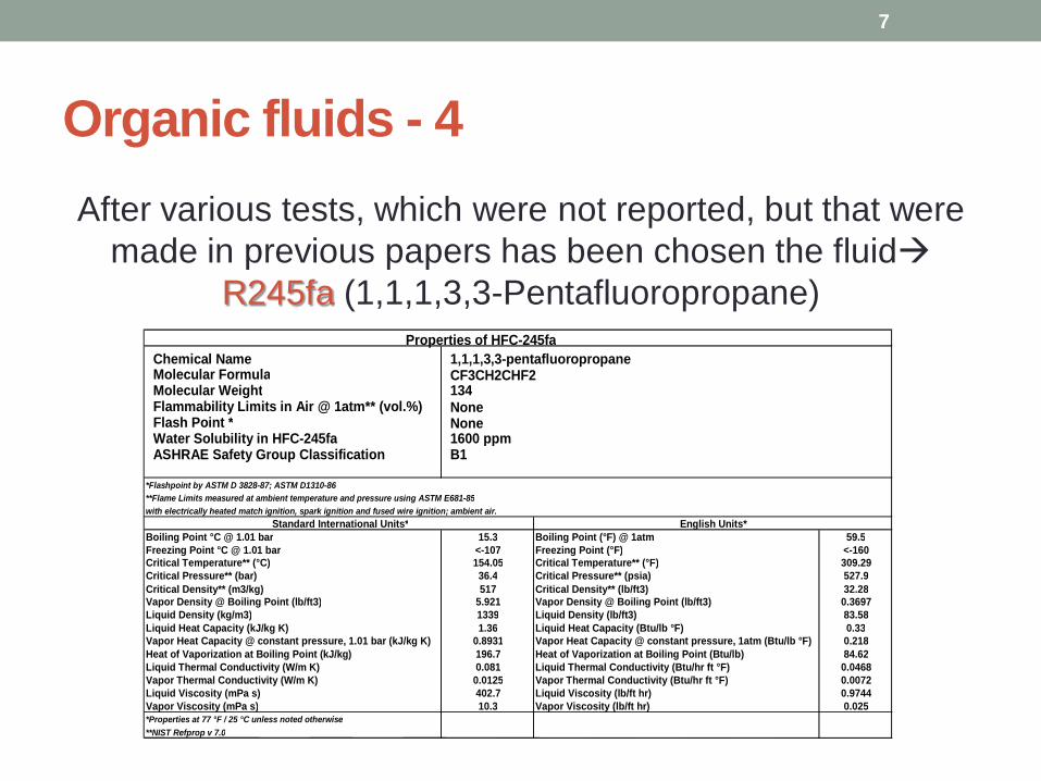
After various tests, which were not reported, but that were made in previous papers has been chosen the fluid
R245fa (1,1,1,3,3-Pentafluoropropane)
7
Organic fluids - 4
Chemical Name 1,1,1,3,3-pentafluoropropane Molecular Formula CF3CH2CHF2 Molecular Weight 134 Flammability Limits in Air @ 1atm** (vol.%) None Flash Point * None Water Solubility in HFC-245fa 1600 ppm ASHRAE Safety Group Classification B1
*Flashpoint by ASTM D 3828-87; ASTM D1310-86 **Flame Limits measured at ambient temperature and pressure using ASTM E681-85 with electrically heated match ignition, spark ignition and fused wire ignition; ambient air. Boiling Point °C @ 1.01 bar 15.3 Boiling Point (°F) @ 1atm 59.5 Freezing Point °C @ 1.01 bar <-107 Freezing Point (°F) <-160 Critical Temperature** (°C) 154.05 Critical Temperature** (°F) 309.29 Critical Pressure** (bar) 36.4 Critical Pressure** (psia) 527.9 Critical Density** (m3/kg) 517 Critical Density** (lb/ft3) 32.28 Vapor Density @ Boiling Point (lb/ft3) 5.921 Vapor Density @ Boiling Point (lb/ft3) 0.3697 Liquid Density (kg/m3) 1339 Liquid Density (lb/ft3) 83.58 Liquid Heat Capacity (kJ/kg K) 1.36 Liquid Heat Capacity (Btu/lb °F) 0.33 Vapor Heat Capacity @ constant pressure, 1.01 bar (kJ/kg K) 0.8931 Vapor Heat Capacity @ constant pressure, 1atm (Btu/lb °F) 0.218 Heat of Vaporization at Boiling Point (kJ/kg) 196.7 Heat of Vaporization at Boiling Point (Btu/lb) 84.62 Liquid Thermal Conductivity (W/m K) 0.081 Liquid Thermal Conductivity (Btu/hr ft °F) 0.0468 Vapor Thermal Conductivity (W/m K) 0.0125 Vapor Thermal Conductivity (Btu/hr ft °F) 0.0072 Liquid Viscosity (mPa s) 402.7 Liquid Viscosity (lb/ft hr) 0.9744 Vapor Viscosity (mPa s) 10.3 Vapor Viscosity (lb/ft hr) 0.025 *Properties at 77 °F / 25 °C unless noted otherwise **NIST Refprop v 7.0
Properties of HFC-245fa
Standard International Units* English Units*
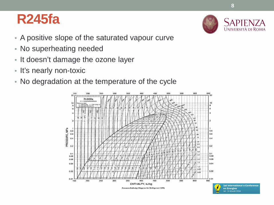
R245fa • A positive slope of the saturated vapour curve • No superheating needed • It doesn’t damage the ozone layer • It’s nearly non-toxic • No degradation at the temperature of the cycle
8
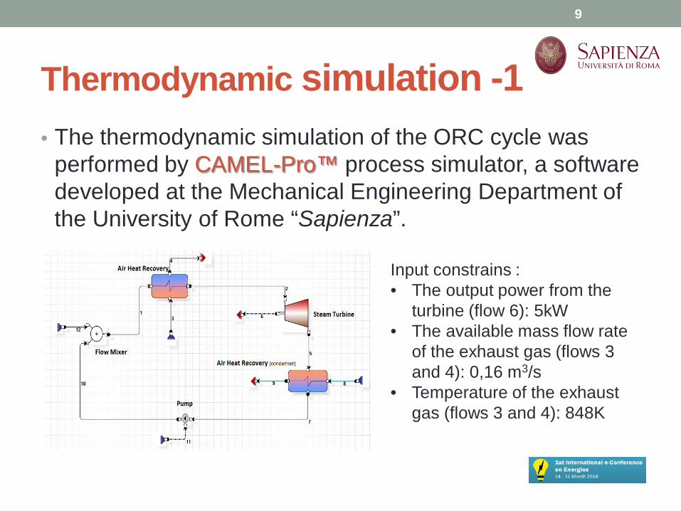
Thermodynamic simulation -1 • The thermodynamic simulation of the ORC cycle was
performed by CAMEL-Pro™ process simulator, a software developed at the Mechanical Engineering Department of the University of Rome “Sapienza”.
9
Input constrains : • The output power from the
turbine (flow 6): 5kW • The available mass flow rate
of the exhaust gas (flows 3 and 4): 0,16 m3/s
• Temperature of the exhaust gas (flows 3 and 4): 848K

• From the thermodynamics tables for R245fa this fluid condenses at 301K with a pressure of 170kPa. Since the expander is a single-stage turbine, it has a limit in the pressure ratio, for this reason the upstream pressure is fixed too.
• Analyzing the very few models available a β = 3,2 has been considered which means a pupstream = 550kPa.
• The turbine adiabatic efficiency has been underrated at ηad = 0.75 to be sure that the outlet power was at least 5 kW and the efficiency of the pump is fixed to 0,9.
10
Thermodynamic simulation -2
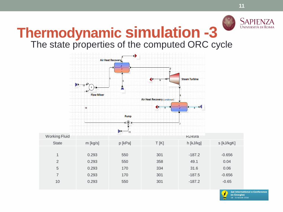
Working Fluid R245fa
State m [kg/s] p [kPa] T [K] h [kJ/kg] s [kJ/kgK]
1
2
5
7
10
0.293
0.293
0.293
0.293
0.293
550
550
170
170
550
301
358
334
301
301
-187.2
49.1
31.6
-187.5
-187.2
-0.656
0.04
0.06
-0.656
-0.65
11
Thermodynamic simulation -3 The state properties of the computed ORC cycle

ORC Expander Briefly considerations • The expander is the fundamental component of the ORC and several
types of expander are used:
• Turbines • Scroll expanders • Screw expanders
Turbines are not very suitable for ORC especially for small-scale plants, but they have the advantage of small dimensions Volumetric machines remain the best choice. Scroll expanders are developed from scroll compressors operating in an expander mode. Screw expanders have the advantage of a simple architecture and they can achieve an outlet power above 20kW
12

ORC Expander Design Objective of the Work feasibility of using a dynamic expander in ORC cycles
The main challenge of the analysis are the imposed size and weight limitations that require a particular design.
13
Proposed expander design method -1 • The procedure adopted to design the radial turbine is based on Rohlik
study • The three independent variable from which started Rohlik optimization
procedure are: 52° < α1 < 83° 0.04 < h1/D2,m < 0.68 0.2 < D2,m/D1 < 0.6 • 0 stator inlet, 1 rotor inlet and 2 rotor outlet. The angle α1 is the
complementary angle formed by the direction of U and V in the velocity triangle. h1 is the height of the rotor blade, D2m diameter of the midspan section at the exit of the rotor and, finally, D1 is the diameter at the rotor inlet.
14
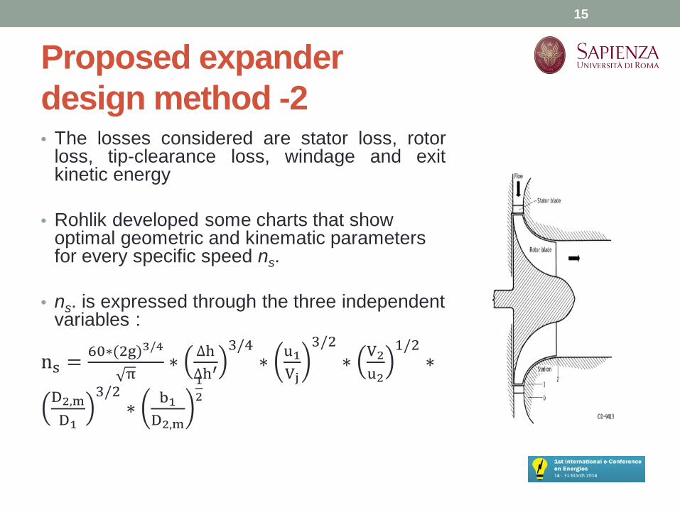
Proposed expander design method -2 • The losses considered are stator loss, rotor
loss, tip-clearance loss, windage and exit kinetic energy
• Rohlik developed some charts that show optimal geometric and kinematic parameters for every specific speed ns.
• ns. is expressed through the three independent variables :
ns = 60∗(2g)3/4
π∗ ∆h
∆h′3/4
∗ u1Vj
3/2∗ V2
u2
1/2∗
D2,mD1
3/2∗ b1
D2,m
12
15

Rohlik chart for blade design
16
Proposed expander design method -3
Proposed expander design method -4
• The charts show the optimal trend, as a function of specific speed, of the ratio of the stator blade height to rotor inlet diameter b1/D1 and the ratio of rotor exit tip diameter to rotor inlet diameter D2e/D1.
• There is an upper limit on D2e/D1 which must not exceed 0,7. Finally,
Rohlik also presented three optimum turbines sections geometry, that correspond to the curve of maximum static efficiency at three values of specific speed.
17
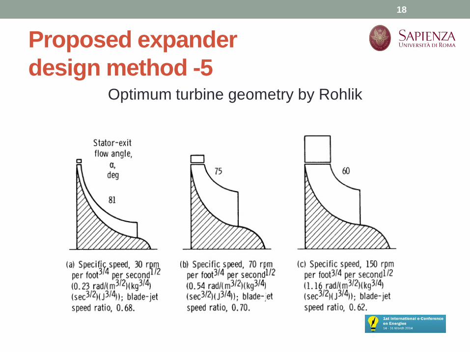
Proposed expander design method -5
Optimum turbine geometry by Rohlik
18
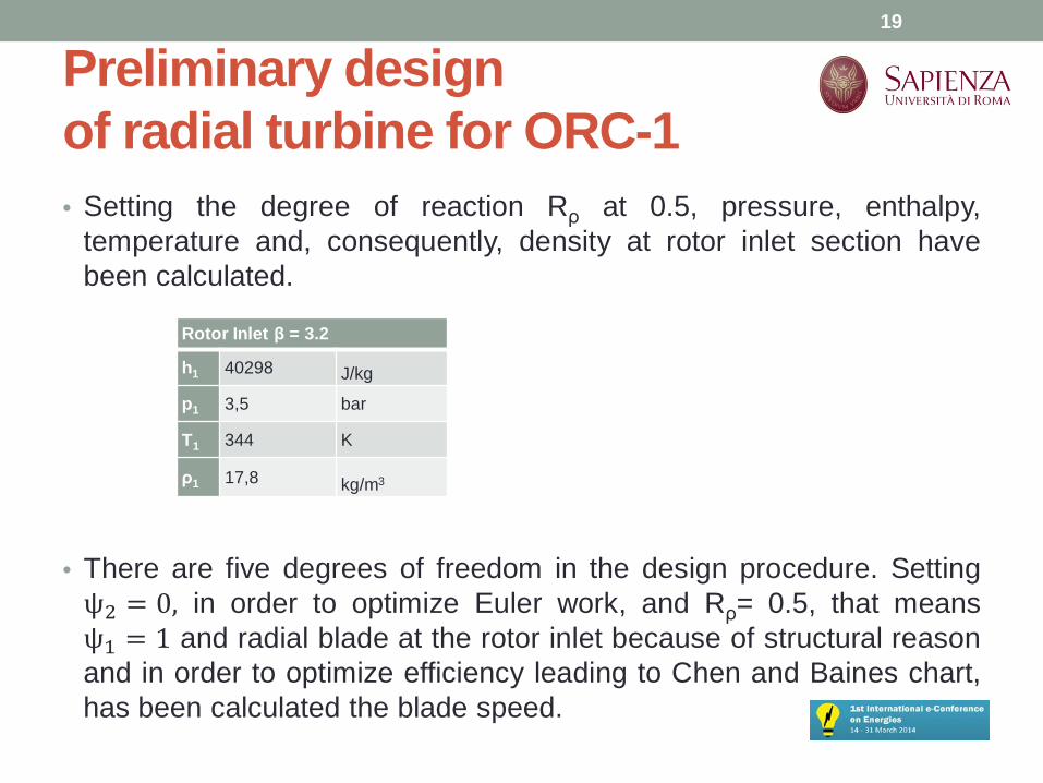
Preliminary design of radial turbine for ORC-1 • Setting the degree of reaction Rρ at 0.5, pressure, enthalpy,
temperature and, consequently, density at rotor inlet section have been calculated.
• There are five degrees of freedom in the design procedure. Setting ψ2 = 0, in order to optimize Euler work, and Rρ= 0.5, that means ψ1 = 1 and radial blade at the rotor inlet because of structural reason and in order to optimize efficiency leading to Chen and Baines chart, has been calculated the blade speed.
19
Rotor Inlet β = 3.2
h1 40298 J/kg
p1 3,5 bar
T1 344 K
ρ1 17,8 kg/m3

Preliminary design of radial turbine for ORC-2 • Inlet section
• Outlet section
20
D1 [m] 0.1 U1 [m] 131
(90- Rohlik) [°] 10 V1t [m] 131
ϕ1 0.18 W1 [m] 23
ψ1 1 V1 [m] 133
b1 [m] 0.0025 V1m [m] 23
b1/D1 0.025 Ma1v 0.9
β1 [°] 90
ϕc 0.25 V2m [m/s] 32
D2m/D1 0.4 U2m [m] 52
D2m [m] 0.04 W2m [m] 62
D2i [m] 0.031 β2 [°] 32
D2e [m] 0.049 ϕ2 0.63
D2e/D1 0.5 ψ2 0
b2 [m] 0.0091 χ2 0.6

Preliminary design of radial turbine for ORC-3 • Blade shape and velocity triangles
21
Blade profile - 1 • First, the mean line has to be defined: we chose to use a
portion of straight line and an arc linked. 20 points as equidistant as possible are considered.
• having the y coordinates of each point, it is possible to calculate the rotational speed at each point.
• Knowing the initial value W1 and the final value W2 of the relative velocity, a linearly increasing trend of W along the mean line of the blade has been assumed.
• The value of the angle β at any point of the mean line has imposed
22
Blade profile - 2 • For temperature a linear progression along the mean line (the
rotor inlet temperature, pressure and density have been calculated from the degree of reaction, entering in the Mollier chart of R245fa) are adopted, while pressures were determined through the relationship between pressure and temperature in the case of the polytrophic expansion.
• The points defining the hub and shroud lines were obtained respectively by subtracting and adding to the coordinates of the mean line, previously defined, the half-height of the blade profile in a direction perpendicular to the tangent to the curve.
• Finally, to maintain a certain uniformity of the meridian velocity
and a constant Euler work on the section, the blades necessary must be twisted.
23

Blade profile - 3 HUB TIP
p. Vt [m/s] U
[m/s]
W
[m/s]
V
[m/s]
β
[°]
α
[°]
Vt
[m/s]
V
[m/s]
W
[m/s]
V
[m/s]
β
[°]
α
[°]
0 131,3 131,3 23,1 133,3 90,0 10,0 131,3 131,3 23,1 133,3 90,0 10,0
1 118,1 118,2 27,5 121,3 90,0 13,1 118,1 118,2 27,5 121,3 90,0 13,1
2 112,7 112,2 29,4 116,5 91,1 14,6 112,1 112,7 29,4 115,9 88,8 14,7
3 106,1 106,2 31,3 110,6 89,8 16,4 104,9 107,4 31,4 109,5 85,5 16,6
4 98,8 100,3 33,1 104,2 87,5 18,5 97,0 102,1 33,4 102,5 81,3 18,8
5 91,2 94,5 34,8 97,6 84,7 20,8 88,8 97,0 35,6 95,4 76,8 21,3
6 83,3 88,8 36,4 90,8 81,4 23,4 80,4 92,1 37,9 88,1 72,0 24,1
7 75,4 83,3 38,0 84,0 78,0 26,2 71,8 87,4 40,3 80,8 67,2 27,3
8 67,3 78,0 39,3 77,2 74,2 29,4 63,1 83,1 42,8 73,6 62,2 31,0
9 59,2 72,9 40,6 70,5 70,4 32,8 54,6 79,1 45,4 66,6 57,3 35,0
10 51,4 68,0 41,7 64,1 66,6 36,7 46,3 75,5 48,2 60,1 52,7 39,6
11 43,7 63,4 42,7 57,9 62,5 41,0 38,3 72,4 51,0 53,9 48,0 44,7
12 36,4 59,1 43,7 52,1 58,7 45,7 30,8 69,7 53,9 48,4 43,8 50,4
13 29,5 55,1 44,5 46,9 54,9 51,0 24,0 67,6 56,8 43,6 39,9 56,6
14 23,0 51,4 45,4 42,2 51,3 57,0 17,9 66,0 59,7 39,7 36,4 63,2
15 17,0 48,1 46,3 38,3 47,9 63,6 12,6 64,9 62,5 36,6 33,3 69,8
16 11,7 45,3 47,4 35,4 44,9 70,8 8,2 64,2 65,2 34,5 30,9 76,2
17 6,9 43,1 48,8 33,5 42,2 78,0 4,7 63,9 67,7 33,1 29,0 81,9
18 3,2 41,7 50,6 33,0 40,5 84,4 2,1 63,8 69,9 32,9 28,0 86,3
19 0,0 41,0 52,5 32,8 38,7 89,9 0,0 64,1 72,0 32,8 27,1 89,9
24
Design procedure results
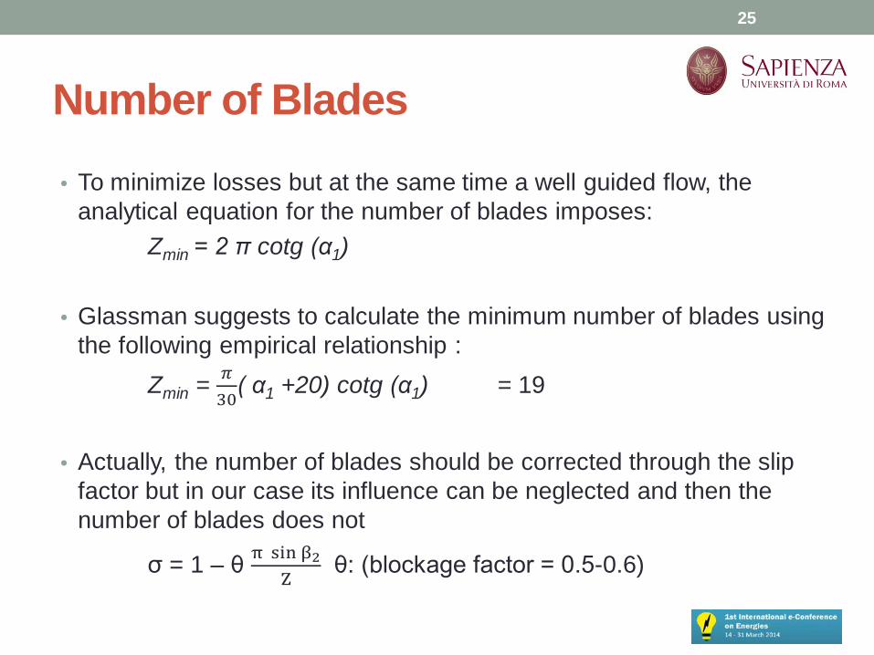
Number of Blades • To minimize losses but at the same time a well guided flow, the
analytical equation for the number of blades imposes: Zmin = 2 π cotg (α1) • Glassman suggests to calculate the minimum number of blades using
the following empirical relationship : Zmin = 𝜋
30( α1 +20) cotg (α1) = 19
• Actually, the number of blades should be corrected through the slip
factor but in our case its influence can be neglected and then the number of blades does not
σ = 1 – θ π sin β2Z
θ: (blockage factor = 0.5-0.6)
25
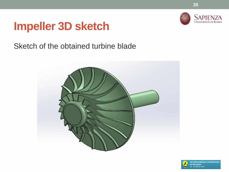
Impeller 3D sketch Sketch of the obtained turbine blade
26
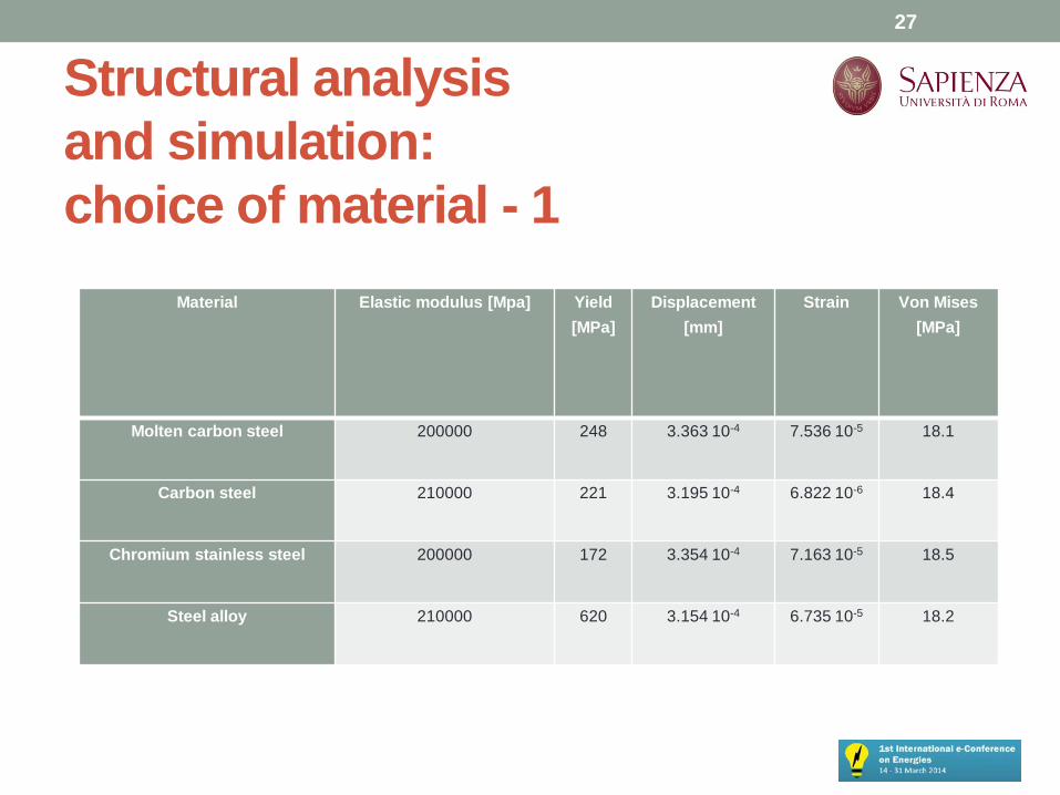
Structural analysis and simulation: choice of material - 1
Material Elastic modulus [Mpa] Yield [MPa]
Displacement [mm]
Strain
Von Mises [MPa]
Molten carbon steel 200000 248 3.363 10-4 7.536 10-5 18.1
Carbon steel 210000 221 3.195 10-4 6.822 10-6 18.4
Chromium stainless steel 200000 172 3.354 10-4 7.163 10-5 18.5
Steel alloy 210000 620 3.154 10-4 6.735 10-5 18.2
27

Structural analysis and simulation: choice of material - 2 The material chosen after the simulations is carbon steel The same material will be used for shaft, stator and volute. On the software, centrifugal force has been set as main stress, setting the value of the rotational speed and the axis of rotation. In this first phase the contribution of the pressure drop has been neglected, and for “computational constrains” only single blade has been simulated. The analysis supply structural resistance to mechanical stress of the blade and the main characteristic of the blade behavior by: • Von Mises stress • Displacement • Strain
28

Structural analysis and simulation: choice of material - 3
29
(Von Mises & Displacement)
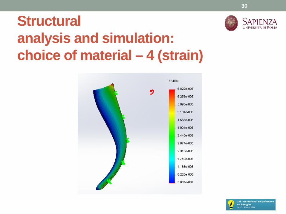
Structural analysis and simulation: choice of material – 4 (strain)
30
Conclusions - 1 • This paper presents the thermodynamic feasibility of an
innovative Organic Rankine Cycle and a preliminary design of its main component, the expander.
• The novelty lies in the choice of this component. The
intention is to see if you can make this device, "breaking" the usual practice, that today uses volumetric expanders
• The main challenge of the analysis are the imposed size
and weight limitations that require a particular design.
31
Conclusions - 2
• Possible system layout has been analyzed and the requirements for a prototypal application investigated.
• The simulation has been important both because it has provided feedback on the values of the expander and supply information on the nominal power of the system and about the behavior of the R245fa, as working fluid.
32
Future developments Further development of the study will include : • to complete the design procedure, including stator and
volute; • to supply a complete layout of the device; • to perform other thermodynamics simulation with other
organic fluids such as R134 to investigate by a thermodynamic study the super-heater and/or a pre-heater components and to study the interaction between components and the organic fluid;
• to perform a market and cost analysis. All this data can be a valid support for the final step of the research, that is the realization of the prototypal ORC system.
33

Small-Scale ORC Energy Recovery System for Wasted Heat: Thermodynamic Feasibility Analysis and Preliminary Expander Design Thank you for your attention!
Roberto Capata, Claudia Toro
Department of Mechanical and Aerospace Engineering, University of Rome “Sapienza”,
[email protected] [email protected]
34