Small Generator Interconnection Completed for Q0415 ... · Study shall provide a list of facilities...
91
Small Generator Interconnection System Impact Study Report Completed for Q0415 (“Interconnection Customer”) Proposed Interconnection 24.9-kV Circuit, SML21, 9.5 Circuit Miles out of South Milford Substation May, 2012
-
Upload
hoangnguyet -
Category
Documents
-
view
214 -
download
0
Transcript of Small Generator Interconnection Completed for Q0415 ... · Study shall provide a list of facilities...
Small Generator Interconnection System Impact Study Report
Completed for Q0415
(“Interconnection Customer”)
Proposed Interconnection 24.9-kV Circuit, SML21,
9.5 Circuit Miles out of South Milford Substation
May, 2012
System Impact Study Report
Q0415 Page 2 May 2012
1.0 DESCRIPTION OF THE GENERATING FACILITY .................................................. 3
2.0 SCOPE OF THE STUDY ................................................................................................... 3
3.0 DESCRIPTION OF PROPOSED INTERCONNECTION ............................................ 3 3.1 STUDY ASSUMPTIONS ......................................................................................................... 6
4.0 REQUIREMENTS .............................................................................................................. 8 4.1 GENERATING FACILITY MODIFICATIONS ............................................................................ 8 4.2 TRANSMISSION MODIFICATIONS ......................................................................................... 9 4.3 EXISTING BREAKER MODIFICATIONS – SHORT-CIRCUIT .................................................. 10 4.4 PROTECTION REQUIREMENTS ........................................................................................... 10 4.5 DATA REQUIREMENTS (RTU)........................................................................................... 11 4.6 COMMUNICATION REQUIREMENTS ................................................................................... 11
4.6.1 For LINE Protection .................................................................................................. 11 4.6.2 For Data Delivery to the Control Centers ................................................................ 11
4.7 SUBSTATION REQUIREMENTS ........................................................................................... 11 4.8 METERING REQUIREMENTS .............................................................................................. 12
5.0 COST ESTIMATE............................................................................................................ 12
6.0 SCHEDULE....................................................................................................................... 12
7.0 PARTICIPATION BY AFFECTED SYSTEMS ........................................................... 12
8.0 APPENDICES ................................................................................................................... 13
System Impact Study Report
Q0415 Page 3 May 2012
1.0 DESCRIPTION OF THE GENERATING FACILITY Interconnection Customer is requesting a material modification at its existing in-service Q0162 later this year. Interconnection Customer plans on replacing the current 50 UTC induction generators with one Ormat, Brush DG, synchronous generator. The output of the plant will not increase from the initial study that was completed prior to Q0162 coming on line in the spring of 2009. The generation facility will remain to be connected to PacifiCorp’s 25-kV circuit South Milford 21 out of PacifiCorp’s (“Distribution Provider”) South Milford Substation. The requested commercial operation date is approximately December 1, 2012. Interconnection Customer will NOT operate this generator as a Qualified Facility as defined by the Public Utility Regulatory Policies Act of 1978 (PURPA). The Transmission Provider has assigned the project “Q0415.”
2.0 SCOPE OF THE STUDY The System Impact Study Report shall consist of a short circuit analysis, a stability analysis, a power flow analysis, voltage drop and flicker studies, protection and set point coordination studies, and grounding reviews, as necessary. The System Impact Study shall state the assumptions upon which it is based, state the results of the analyses, and provide the requirement or potential impediments to providing the requested interconnection service, including a preliminary indication of the cost and length of time that would be necessary to correct any problems identified in those analyses and implement the interconnection. The System Impact Study shall provide a list of facilities that are required as a result of the Interconnection Request and non-binding good faith estimates of cost responsibility and time to construct. A Stability Study is currently being drafted and will be sent to Interconnection Customer under separate cover at a later date.
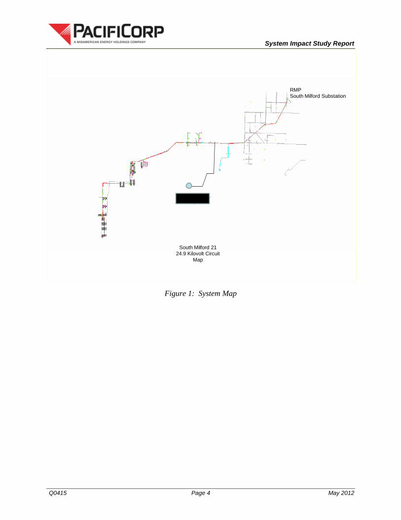
3.0 DESCRIPTION OF PROPOSED INTERCONNECTION The Project’s proposed interconnection is located on 25-kV circuit South Milford 21 out of PacifiCorp’s (“Distribution Provider”) South Milford Substation in Beaver County, Utah. Figure 1 below, is a map that illustrates the interconnection of the proposed generation facility to the Transmission Provider’s system.
System Impact Study Report
Q0415 Page 4 May 2012
South Milford 21 24.9 Kilovolt Circuit
Map
RMP South Milford Substation
Thermo No. 1 BE-01, LLC
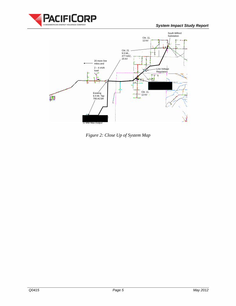
Figure 1: System Map
System Impact Study Report
Q0415 Page 5 May 2012
South Milford Substation
Thermo No. 1 BE-01 LLC Plant 11 MW Max.Output
Existing 6.5 Mi. Tap 795 ACSR
Ckt. 21 9.5 Mi., 477 AAC, 25 kV
Line Voltage Regulators
Ckt. 11, 12 kV
Ckt. 11, 12 kV
20 more line miles and
2 – 4 mVA load
Circle 4 Farms BioFuel CoGen Plant – 850 kW Peak Output
Figure 2: Close Up of System Map
System Impact Study Report
Q0415 Page 6 May 2012
Change of ownership
1
M
R
South Milford Sub
R
R
R
46kV
6.9 miles
6.5 Miles
25kV
Q0162Substation
25kV
2.8 miles
Q0332
Q0333
2.6 miles
Point of Interconnection
11 12
12.47kV
17.5 MVA
Q 0415
Disconnect all existing induction generators
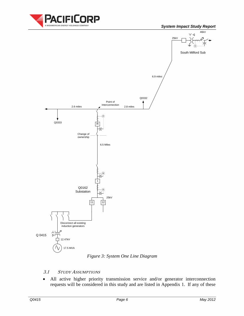
Figure 3: System One Line Diagram
3.1 STUDY ASSUMPTIONS • All active higher priority transmission service and/or generator interconnection
requests will be considered in this study and are listed in Appendix 1. If any of these

System Impact Study Report
Q0415 Page 7 May 2012
requests are withdrawn, the Transmission Provider reserves the right to restudy this request, as the results and conclusions contained within this study could significantly change.
• For study purposes there are two separate queues: o Transmission Service Queue: to the extent practical, all network upgrades that are
required to accommodate active transmission service requests and are expected to be in-service on or after the Interconnection Customer’s requested in-service date for the Project will be modeled in this study.
o Generation Interconnection Queue: when relevant, interconnection facilities associated with higher queue interconnection requests will be modeled in this study. However, network upgrades required to provide delivery will only be modeled for projects which have requested network resource integration service only or qualified facility status. No generation will be simulated from any higher queued project unless a commitment has been made to obtain transmission service.
• The Interconnection Customer’s request for interconnection service in and of itself
does not convey transmission service.
• This study assumes the Project will be integrated into Transmission Provider’s system at the agreed upon and/or proposed point of interconnection.
• The Interconnection Customer will construct and own the any facilities required
between the point of interconnection and the Project.
• Generator tripping may be required for certain outages.
• All facilities will meet or exceed the minimum WECC, NERC, and Transmission Provider performance and design standards.
• This report is based on information available at the time of the study. It is the
Interconnection Customer’s responsibility to check the Transmission Provider’s web site regularly for transmission system updates (http://www.pacificorp.com/tran.html)
• Metered loading on the South Milford 21 (SML21) circuit has been verified as not
significantly different from the last time it was studied for the same generation output. Daily peaks range from 2 – 4 MW with minimum values about half of the peaks. This means that there could be as little as 1 MW of load on the circuit during off peak periods.
• This study assumes that the generation proposed here will be brought on line and off
line without significant step changes to circuit voltage, including during a system fault.
System Impact Study Report
Q0415 Page 8 May 2012
• At start up KW output of the generator is gradually raised up to the maximum
available net output.
• When the plant is shut down generator output is ramped down to zero and disconnected.
• In case of a critical fault the turbine valves will close causing a fast ramp down and then the generator breaker will open stepping down to no generation.
• This unit operates exactly like the Ormat bottom cycle units that are currently in operation at Blundell.
• It is assumed that the parasitic loads from the operation (especially startup) of the generator will conform to the following statement as well as other requirements which may be stated elsewhere in this SIS document: “The same start up procedure that the project currently operates under will be used with the new larger generator. There are no changes required to the well field loads or start up from the existing plant.”
4.0 REQUIREMENTS
4.1 GENERATING FACILITY MODIFICATIONS The Generation and Interconnection facilities owned by the interconnection customer are required to operate under automatic voltage control with the voltage sensed electrically at the point of interconnection or
in power factor control mode operating at unity power factor sensed at the point of interconnection. The generating and interconnecting facility should have sufficient reactive capacity to enable the delivery of 100 percent of the plant output to the point of interconnection at unity power factor measured at 1.0 per unit voltage under steady state conditions.
Generators capable of operating under voltage control with a voltage droop are required to do so. Studies will be required to coordinate the voltage droop setting with other facilities in the area. In general, generation and interconnection facilities should be operated so as to maintain the voltage at the point of interconnection between 1.01 pu to 1.04 pu. At the Transmission Provider’s discretion, these values might be adjusted depending on the operating conditions. Within this voltage range, the generating and interconnecting facilities should operate so as to minimize the reactive interchange between the generation/interconnection facilities and the Transmission Provider’s system (delivery of power at the point of interconnection at approximately unity power factor). The voltage control settings of the generation and interconnection facilities must be coordinated with the Transmission Provider prior to energization (or interconnection). The reactive compensation must be designed such that the discreet switching of the reactive device (if required by the interconnection customer) does not cause step voltage changes greater than +/-3% on the Transmission Provider’s system.
System Impact Study Report
Q0415 Page 9 May 2012
All wind turbines must meet the FERC/WECC low voltage ride-through requirements as specified in the interconnection agreement. As per NERC standard VAR-001-1a, the Transmission Provider is required to specify voltage or reactive power schedule at the Point of Interconnection. Under normal conditions, the Transmission Provider’s system should not supply reactive power to the generation/interconnection facilities.
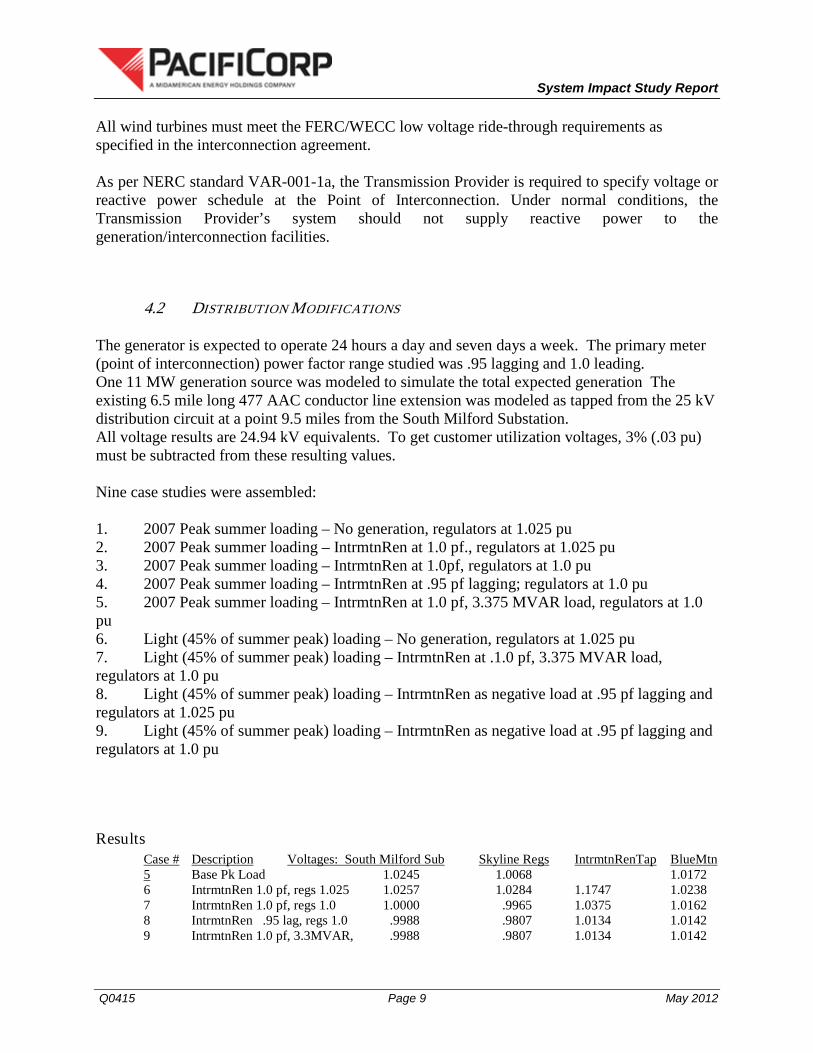
4.2 DISTRIBUTION MODIFICATIONS The generator is expected to operate 24 hours a day and seven days a week. The primary meter (point of interconnection) power factor range studied was .95 lagging and 1.0 leading. One 11 MW generation source was modeled to simulate the total expected generation The existing 6.5 mile long 477 AAC conductor line extension was modeled as tapped from the 25 kV distribution circuit at a point 9.5 miles from the South Milford Substation. All voltage results are 24.94 kV equivalents. To get customer utilization voltages, 3% (.03 pu) must be subtracted from these resulting values. Nine case studies were assembled: 1. 2007 Peak summer loading – No generation, regulators at 1.025 pu 2. 2007 Peak summer loading – IntrmtnRen at 1.0 pf., regulators at 1.025 pu 3. 2007 Peak summer loading – IntrmtnRen at 1.0pf, regulators at 1.0 pu 4. 2007 Peak summer loading – IntrmtnRen at .95 pf lagging; regulators at 1.0 pu 5. 2007 Peak summer loading – IntrmtnRen at 1.0 pf, 3.375 MVAR load, regulators at 1.0 pu 6. Light (45% of summer peak) loading – No generation, regulators at 1.025 pu 7. Light (45% of summer peak) loading – IntrmtnRen at .1.0 pf, 3.375 MVAR load, regulators at 1.0 pu 8. Light (45% of summer peak) loading – IntrmtnRen as negative load at .95 pf lagging and regulators at 1.025 pu 9. Light (45% of summer peak) loading – IntrmtnRen as negative load at .95 pf lagging and regulators at 1.0 pu
Results Case # Description Voltages: South Milford Sub Skyline Regs IntrmtnRenTap BlueMtn5 Base Pk Load 1.0245 1.0068 1.0172
6 IntrmtnRen 1.0 pf, regs 1.025 1.0257 1.0284 1.1747 1.0238 7 IntrmtnRen 1.0 pf, regs 1.0 1.0000 .9965 1.0375 1.0162 8 IntrmtnRen .95 lag, regs 1.0 .9988 .9807 1.0134 1.0142 9 IntrmtnRen 1.0 pf, 3.3MVAR, .9988 .9807 1.0134 1.0142
System Impact Study Report
Q0415 Page 10 May 2012
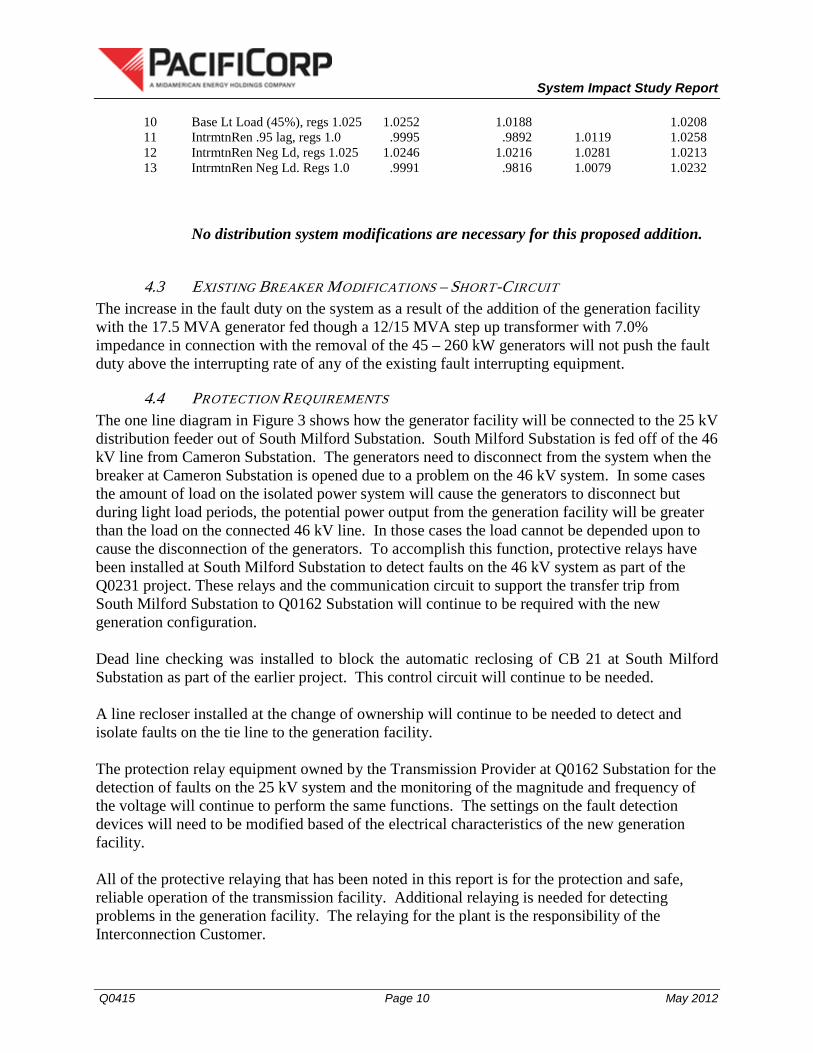
10 Base Lt Load (45%), regs 1.025 1.0252 1.0188 1.0208 11 IntrmtnRen .95 lag, regs 1.0 .9995 .9892 1.0119 1.0258 12 IntrmtnRen Neg Ld, regs 1.025 1.0246 1.0216 1.0281 1.0213 13 IntrmtnRen Neg Ld. Regs 1.0 .9991 .9816 1.0079 1.0232
No distribution system modifications are necessary for this proposed addition.
4.3 EXISTING BREAKER MODIFICATIONS – SHORT-CIRCUIT The increase in the fault duty on the system as a result of the addition of the generation facility with the 17.5 MVA generator fed though a 12/15 MVA step up transformer with 7.0% impedance in connection with the removal of the 45 – 260 kW generators will not push the fault duty above the interrupting rate of any of the existing fault interrupting equipment.
4.4 PROTECTION REQUIREMENTS The one line diagram in Figure 3 shows how the generator facility will be connected to the 25 kV distribution feeder out of South Milford Substation. South Milford Substation is fed off of the 46 kV line from Cameron Substation. The generators need to disconnect from the system when the breaker at Cameron Substation is opened due to a problem on the 46 kV system. In some cases the amount of load on the isolated power system will cause the generators to disconnect but during light load periods, the potential power output from the generation facility will be greater than the load on the connected 46 kV line. In those cases the load cannot be depended upon to cause the disconnection of the generators. To accomplish this function, protective relays have been installed at South Milford Substation to detect faults on the 46 kV system as part of the Q0231 project. These relays and the communication circuit to support the transfer trip from South Milford Substation to Q0162 Substation will continue to be required with the new generation configuration. Dead line checking was installed to block the automatic reclosing of CB 21 at South Milford Substation as part of the earlier project. This control circuit will continue to be needed. A line recloser installed at the change of ownership will continue to be needed to detect and isolate faults on the tie line to the generation facility. The protection relay equipment owned by the Transmission Provider at Q0162 Substation for the detection of faults on the 25 kV system and the monitoring of the magnitude and frequency of the voltage will continue to perform the same functions. The settings on the fault detection devices will need to be modified based of the electrical characteristics of the new generation facility. All of the protective relaying that has been noted in this report is for the protection and safe, reliable operation of the transmission facility. Additional relaying is needed for detecting problems in the generation facility. The relaying for the plant is the responsibility of the Interconnection Customer.
System Impact Study Report
Q0415 Page 11 May 2012
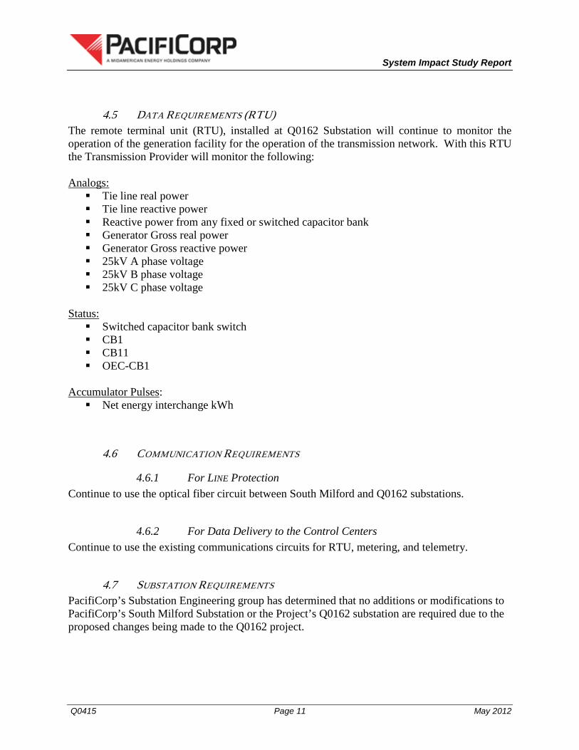
4.5 DATA REQUIREMENTS (RTU) The remote terminal unit (RTU), installed at Q0162 Substation will continue to monitor the operation of the generation facility for the operation of the transmission network. With this RTU the Transmission Provider will monitor the following:
Tie line real power Analogs:
Tie line reactive power Reactive power from any fixed or switched capacitor bank Generator Gross real power Generator Gross reactive power 25kV A phase voltage 25kV B phase voltage 25kV C phase voltage
Switched capacitor bank switch Status:
CB1 CB11 OEC-CB1
Accumulator Pulses Net energy interchange kWh
:
4.6 COMMUNICATION REQUIREMENTS
4.6.1 For LINE Protection Continue to use the optical fiber circuit between South Milford and Q0162 substations.
4.6.2 For Data Delivery to the Control Centers Continue to use the existing communications circuits for RTU, metering, and telemetry.
4.7 SUBSTATION REQUIREMENTS PacifiCorp’s Substation Engineering group has determined that no additions or modifications to PacifiCorp’s South Milford Substation or the Project’s Q0162 substation are required due to the proposed changes being made to the Q0162 project.

System Impact Study Report
Q0415 Page 12 May 2012
4.8 METERING REQUIREMENTS No changes are required to the existing metering. The metering station is rated at 600 amps using 400/5 CT’s rated at 600 amps with an RF on 1.5. The customer generation changes will not require changing instrument transformers or require meter reprogramming.
5.0 COST ESTIMATE Costs for all excavation, duct installation and easements shall be borne by the Interconnection Customer and are NOT included in this estimate. This estimate is as accurate as possible given the level of study that has been undertaken to-date and approximates the costs incurred by the Transmission Provider to interconnect this generator to Transmission Provider’s electrical transmission system. The Interconnection Customer will be responsible for all actual costs, regardless of the estimated costs communicated to or approved by the Interconnection Customer. A more detailed estimate is calculated during the Facilities Study.
Direct Assigned
Protection and Control Modifications $ 16,000 Review, modification, installation and confirmation of proper relay settings to
accommodate the new generator
Subtotal Direct Assigned $16,000
Estimated Total Project Costs $ 16,000
6.0 SCHEDULE Further details regarding the schedule will be available through the Facilities Study when a more detailed estimate has been prepared. The schedule is driven by the date that the Small Generator Interconnect Agreement is signed. Changes in this date affect the entire schedule. Please note that this timeframe may not support the Interconnection Customer’s requested in-service date of December 1, 2012. Results of the Transient Stability Study, currently in process, may also have an effect on this project.
7.0 PARTICIPATION BY AFFECTED SYSTEMS No Affected Systems were identified in relation to this Interconnection Request.
System Impact Study Report
Q0415 Page 13 May 2012
8.0 APPENDICES Appendix 1: Higher Priority Requests Appendix 2: Property Requirements for Point of Interconnection Substation (existing)

System Impact Study Report
Q0415 Page 14 May 2012
APPENDIX 1: HIGHER PRIORITY REQUESTS
All active higher priority transmission service and/or generator interconnection requests will be considered in this study and are identified below. If any of these requests are withdrawn, the Transmission Provider reserves the right to restudy this request, as the results and conclusions contained within this study could significantly change. Transmission/Generation Interconnection Queue Requests considered: There are no higher priority requests in the in queue that affect this interconnection request.

System Impact Study Report
Q0415 Page 15 May 2012
Appendix 2: Property Requirements for Point of
Interconnection Substation (Currently Existing)
The following applies to property acquired by an Interconnection Customer on which a point of interconnection substation will be built to accommodate the Interconnection Customer’s project. The property will ultimately be assigned to PacifiCorp, the Transmission Provider.
• Property must be environmentally, physically and operationally acceptable to the Transmission Provider without any material defects of title (or as deemed acceptable to the Transmission Provider) and without unacceptable encumbrances. The property shall be a permitted or permittable use in all zoning districts. Property lines shall be surveyed and show all encumbrances, roads (private or public); easements (prescriptive or express) etc.
Examples of potentially unacceptable environmental, physical, or operational conditions:
• Environmentally unacceptable conditions could include but are not limited to known contamination of site; evidence of environmental contamination by any dangerous, hazardous or toxic materials as defined by any governmental agency; property is in violation of building, health, safety, environmental, fire, land use, zoning or other such regulation, ordinances, or statues of any governmental entities having jurisdiction over the property; underground or above ground storage tanks; known remediation sites on property; ongoing mitigation activities or monitoring activities; asbestos; lead-based paint, etc. At a minimum, a phase I environmental study is required for company land being acquired in fee. Evidence will be required prior to execution of the interconnection agreement.
• Physically unacceptable conditions could include but are not limited to inadequate drainage; in flood zone; erosion issues; wetland overlays; threatened and endangered species; archeological or culturally sensitive areas; inadequate sub-surface elements, etc. Geotechnical studies are required by the Transmission Provider.
• Operationally unacceptable conditions could include but are not limited to inadequate access for company equipment; existing structures on land that require removal prior to building of substation; ongoing maintenance for landscaping or extensive landscape requirements; ongoing homeowner's or CC&R's that are not acceptable to the Transmission Provider.

System Impact Study Report
Q0415 Page 16 May 2012
• Property should be acquired by fee ownership. If fee acquisition is not possible, then the term shall be perpetual and the use exclusive and provide the Transmission Provider with all property rights it deems necessary (perpetual easement). All contracts are subject to the Transmission Provider’s approval prior to execution.
• The Interconnection customer is required to identify any and all land rights to the subject property, which are to be retained by the Interconnection customer prior to conveying property. All retained land rights are subject to the Transmission Provider’s approval.
• If the Interconnection Customer is building facilities to be owned by the Transmission
Provider, then the Interconnection Customer must obtain all permits required by all relevant jurisdictions for the use including but not limited to conditional use permits, Certificates of Public Convenience and Necessity, California Environmental Quality Act, etc., as well as all construction permits for the project
• Interconnection Customer will not reimburse through network upgrades for more than the
market value of the property.
• Property must be assignable to company and without litigation, suit, liens, condemnation actions, foreclosures actions, etc.
Small Generator Interconnection Dynamic Stability Study
Completed for Q0415
(“Interconnection Customer”)
Proposed Interconnection 25-kV Circuit, SML21, out of South Milford Substation
May, 2012
i
Table of Contents
Executive Summary i
1. Description of Project 1-1 2. Study Assumptions 2-1 3. Transient Analysis 3-1 4. Conclusions 4-1 5. Appendices 5-1
A. Cameron – Milford 138kV line open (current) A-1 B. Cameron – Milford 138kV line close (future) B-1
ii
Executive Summary Interconnection Customer is requesting a material modification at its existing in-service Q0162 later this year. Interconnection Customer plans on replacing the current 50 UTC induction generators with one Ormat, Brush DG, synchronous generator. The output of the plant will not increase from the initial study that was completed prior to Q0162 coming on line in the spring of 2009. The generation facility will remain to be connected to PacifiCorp’s 25-kV circuit South Milford 21 out of PacifiCorp’s (“Distribution Provider”) South Milford Substation. The requested commercial operation date is approximately December 1, 2012. Interconnection Customer will NOT operate this generator as a Qualified Facility as defined by the Public Utility Regulatory Policies Act of 1978 (PURPA). The Transmission Provider has assigned the project “Q0415.” Transient stability studies were completed with the future Cameron - Milford 138 kV line open and closed. This transmission line is waiting for a permit and the scheduled in-service date is in summer 2013. Transient stability analysis was simulated for various local area disturbances in the 138 kV transmission network with the proposed 2012 system conditions modeled. Results identified that with the Ormat, Brush DG, synchronous generator (Salient Pole Generator Model); the Project will ride through ALL simulated local area contingencies, but poor damping may occur with the Cameron – Milford 138kV line open configuration (existing system). A power system stabilizer (PSS) is highly recommended for the new interconnect generation.
Note, project modeling is based on data provided by the developer and/or the developer’s equipment suppliers.
1- 1
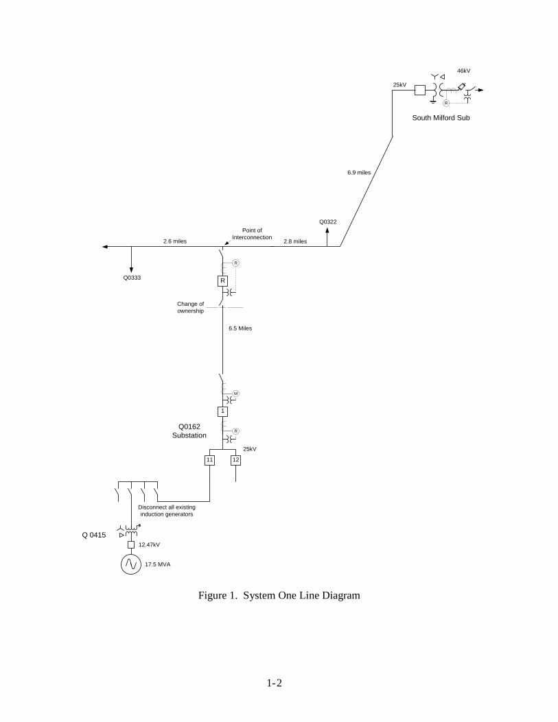
1. Description of Project The Project’s proposed interconnection is located on a 25-kV circuit (South Milford 21) out of PacifiCorp’s (“Distribution Provider”) South Milford Substation in Beaver County, Utah. A preliminary electrical single line diagram depicting the Project’s substation is shown in Figure 1. It is proposed to interconnect the 11 MW geothermal generator at the Q0162 substation. The Project includes one 25/12 kV transformer with a capacity of 15MVA. The transformer impedance is 7% on a 12MVA base.
1- 2
Change of ownership
1
M
R
South Milford Sub
R
R
R
46kV
6.9 miles
6.5 Miles
25kV
Q0162Substation
25kV
2.8 miles
Q0322
Q0333
2.6 miles
Point of Interconnection
11 12
12.47kV
17.5 MVA
Q 0415
Disconnect all existing induction generators
Figure 1. System One Line Diagram
2- 1
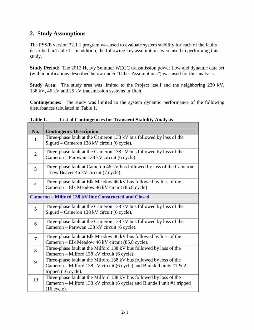
2. Study Assumptions The PSS/E version 32.1.1 program was used to evaluate system stability for each of the faults described in Table 1. In addition, the following key assumptions were used in performing this study. Study Period: The 2012 Heavy Summer WECC transmission power flow and dynamic data set (with modifications described below under “Other Assumptions”) was used for this analysis. Study Area: The study area was limited to the Project itself and the neighboring 230 kV, 138 kV, 46 kV and 25 kV transmission systems in Utah. Contingencies: The study was limited to the system dynamic performance of the following disturbances tabulated in Table 1. Table 1. List of Contingencies for Transient Stability Analysis
No.
Contingency Description
1 Three-phase fault at the Cameron 138 kV bus followed by loss of the Sigurd – Cameron 138 kV circuit (6 cycle).
2 Three-phase fault at the Cameron 138 kV bus followed by loss of the Cameron – Parowan 138 kV circuit (6 cycle).
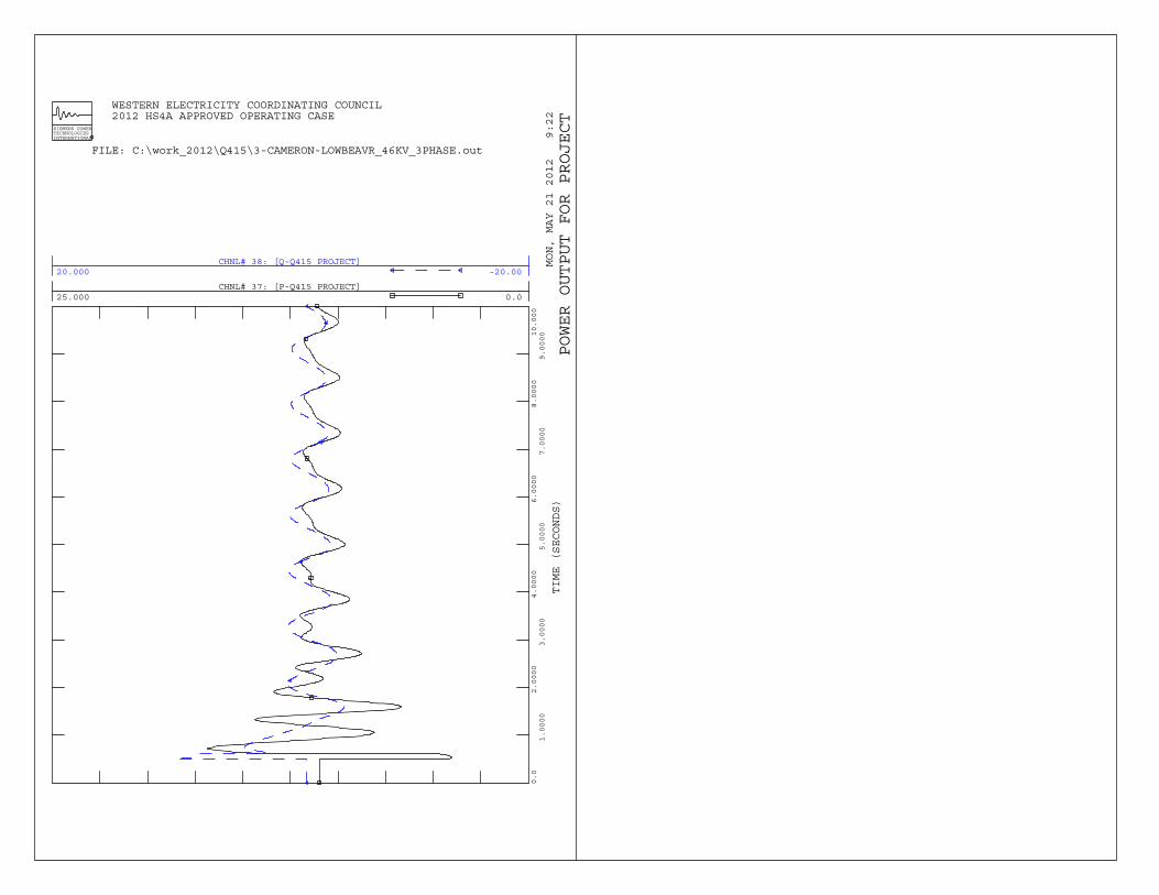
3 Three-phase fault at Cameron 46 kV bus followed by loss of the Cameron – Low Beaver 46 kV circuit (7 cycle).
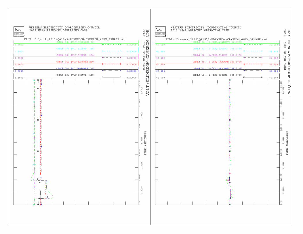
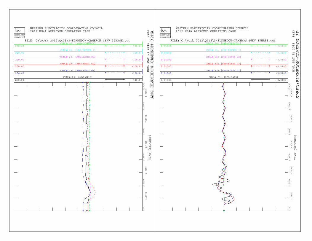
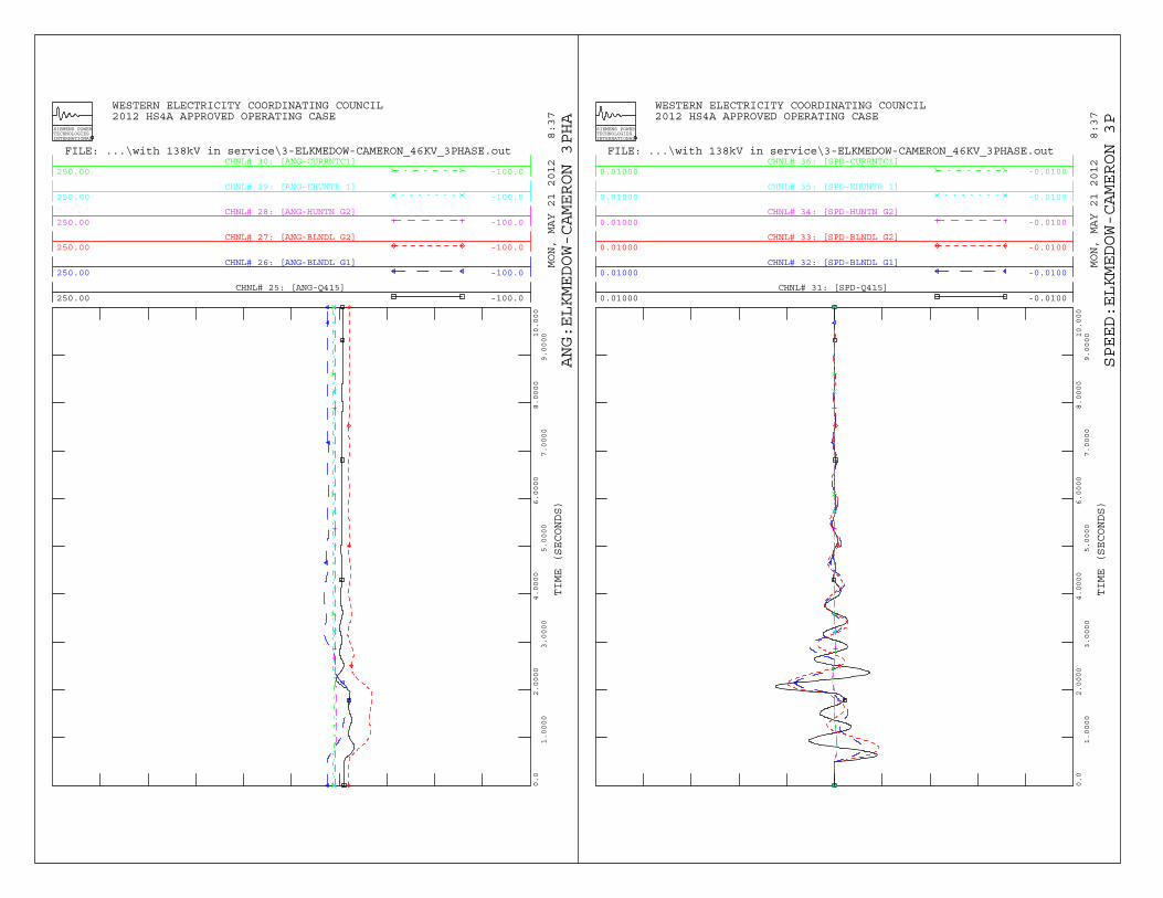
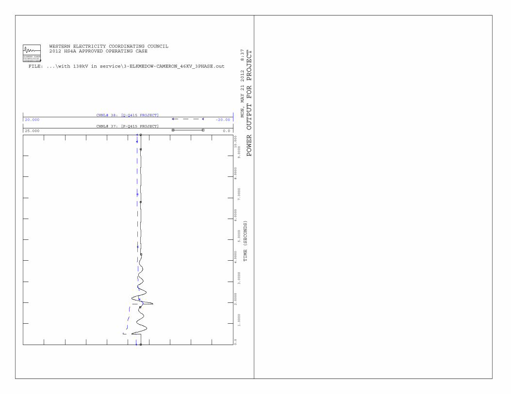
4 Three-phase fault at Elk Meadow 46 kV bus followed by loss of the Cameron – Elk Meadow 46 kV circuit (85.8 cycle)
Cameron – Milford 138 kV line Constructed and Closed
5 Three-phase fault at the Cameron 138 kV bus followed by loss of the Sigurd – Cameron 138 kV circuit (6 cycle).
6 Three-phase fault at the Cameron 138 kV bus followed by loss of the Cameron – Parowan 138 kV circuit (6 cycle).
7 Three-phase fault at Elk Meadow 46 kV bus followed by loss of the Cameron – Elk Meadow 46 kV circuit (85.8 cycle).
8 Three-phase fault at the Milford 138 kV bus followed by loss of the Cameron – Milford 138 kV circuit (6 cycle).
9 Three-phase fault at the Milford 138 kV bus followed by loss of the Cameron – Milford 138 kV circuit (6 cycle) and Blundell units #1 & 2 tripped (16 cycle).
10 Three-phase fault at the Milford 138 kV bus followed by loss of the Cameron – Milford 138 kV circuit (6 cycle) and Blundell unit #1 tripped (16 cycle).
2- 2
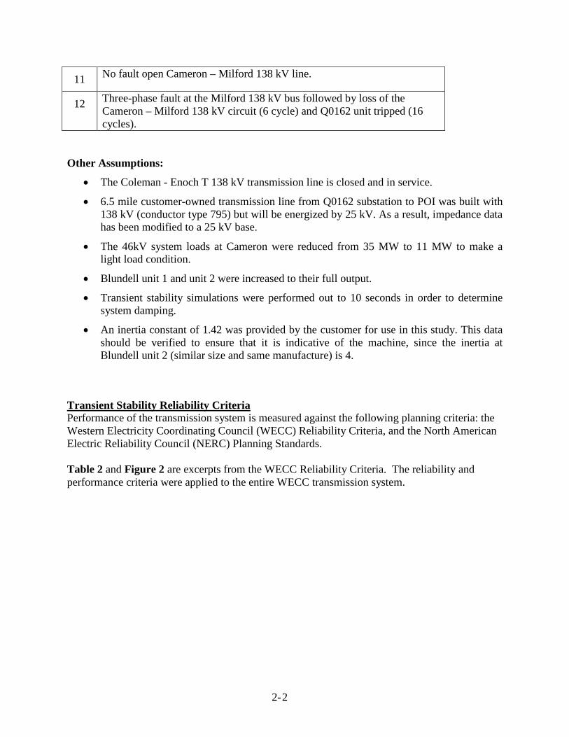
11 No fault open Cameron – Milford 138 kV line.
12 Three-phase fault at the Milford 138 kV bus followed by loss of the Cameron – Milford 138 kV circuit (6 cycle) and Q0162 unit tripped (16 cycles).
Other Assumptions:
• The Coleman - Enoch T 138 kV transmission line is closed and in service.
• 6.5 mile customer-owned transmission line from Q0162 substation to POI was built with 138 kV (conductor type 795) but will be energized by 25 kV. As a result, impedance data has been modified to a 25 kV base.
• The 46kV system loads at Cameron were reduced from 35 MW to 11 MW to make a light load condition.
• Blundell unit 1 and unit 2 were increased to their full output.
• Transient stability simulations were performed out to 10 seconds in order to determine system damping.
• An inertia constant of 1.42 was provided by the customer for use in this study. This data should be verified to ensure that it is indicative of the machine, since the inertia at Blundell unit 2 (similar size and same manufacture) is 4.
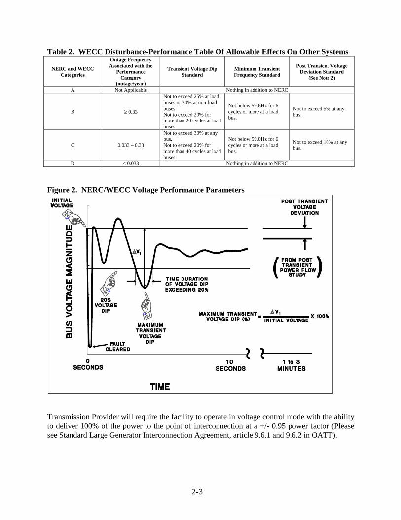
Transient Stability Reliability Criteria Performance of the transmission system is measured against the following planning criteria: the Western Electricity Coordinating Council (WECC) Reliability Criteria, and the North American Electric Reliability Council (NERC) Planning Standards. Table 2 and Figure 2 are excerpts from the WECC Reliability Criteria. The reliability and performance criteria were applied to the entire WECC transmission system.
2- 3
Table 2. WECC Disturbance-Performance Table Of Allowable Effects On Other Systems
NERC and WECC Categories
Outage Frequency Associated with the
Performance Category
(outage/year)
Transient Voltage Dip Standard
Minimum Transient Frequency Standard
Post Transient Voltage Deviation Standard
(See Note 2)
A Not Applicable Nothing in addition to NERC
B ≥ 0.33
Not to exceed 25% at load buses or 30% at non-load buses. Not to exceed 20% for more than 20 cycles at load buses.
Not below 59.6Hz for 6 cycles or more at a load bus.
Not to exceed 5% at any bus.
C 0.033 – 0.33
Not to exceed 30% at any bus. Not to exceed 20% for more than 40 cycles at load buses.
Not below 59.0Hz for 6 cycles or more at a load bus.
Not to exceed 10% at any bus.
D < 0.033 Nothing in addition to NERC
Figure 2. NERC/WECC Voltage Performance Parameters
Transmission Provider will require the facility to operate in voltage control mode with the ability to deliver 100% of the power to the point of interconnection at a +/- 0.95 power factor (Please see Standard Large Generator Interconnection Agreement, article 9.6.1 and 9.6.2 in OATT).

2- 4
During normal voltage conditions, the voltage control scheme should operate to minimize the reactive exchange between the Interconnection Customer’s Project and Transmission Provider system or as directed by the system operator. All generators must meet the Transmission Provider’s low voltage ride-through requirements as specified in the interconnection agreement.
3-1
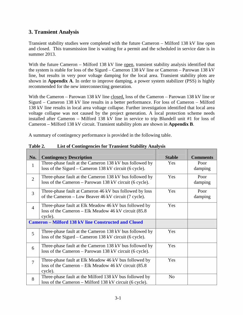
3. Transient Analysis Transient stability studies were completed with the future Cameron – Milford 138 kV line open and closed. This transmission line is waiting for a permit and the scheduled in service date is in summer 2013.
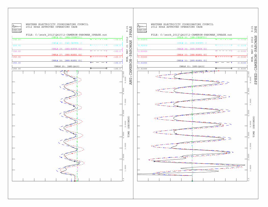
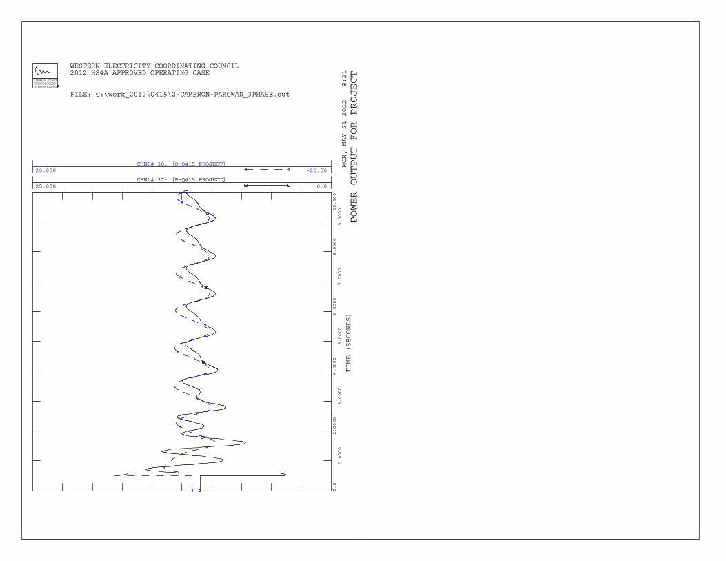
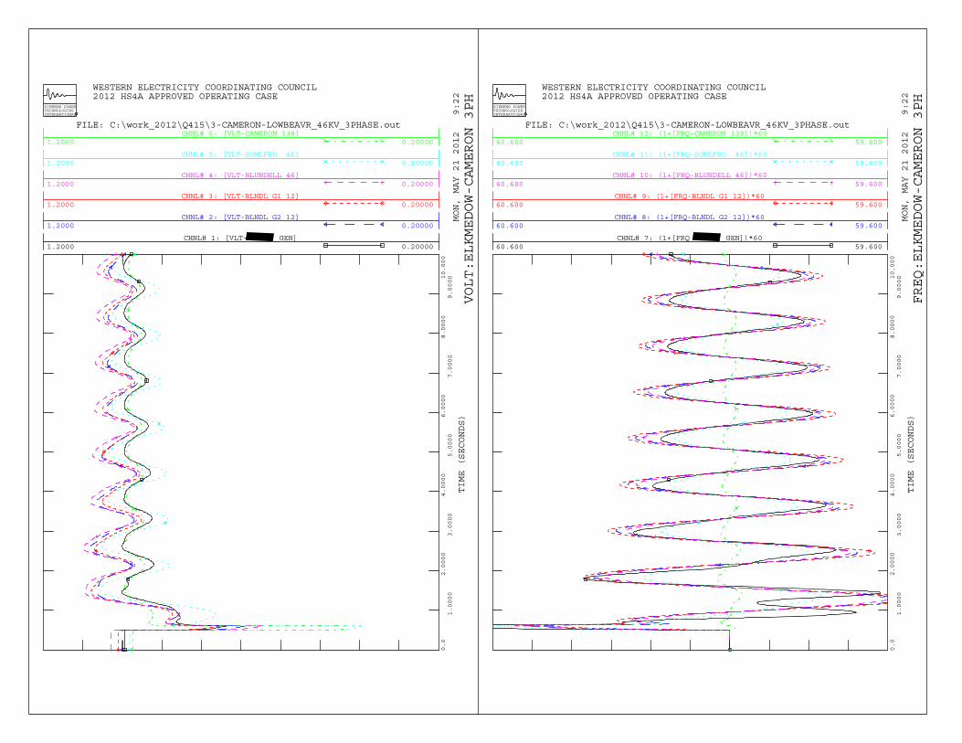
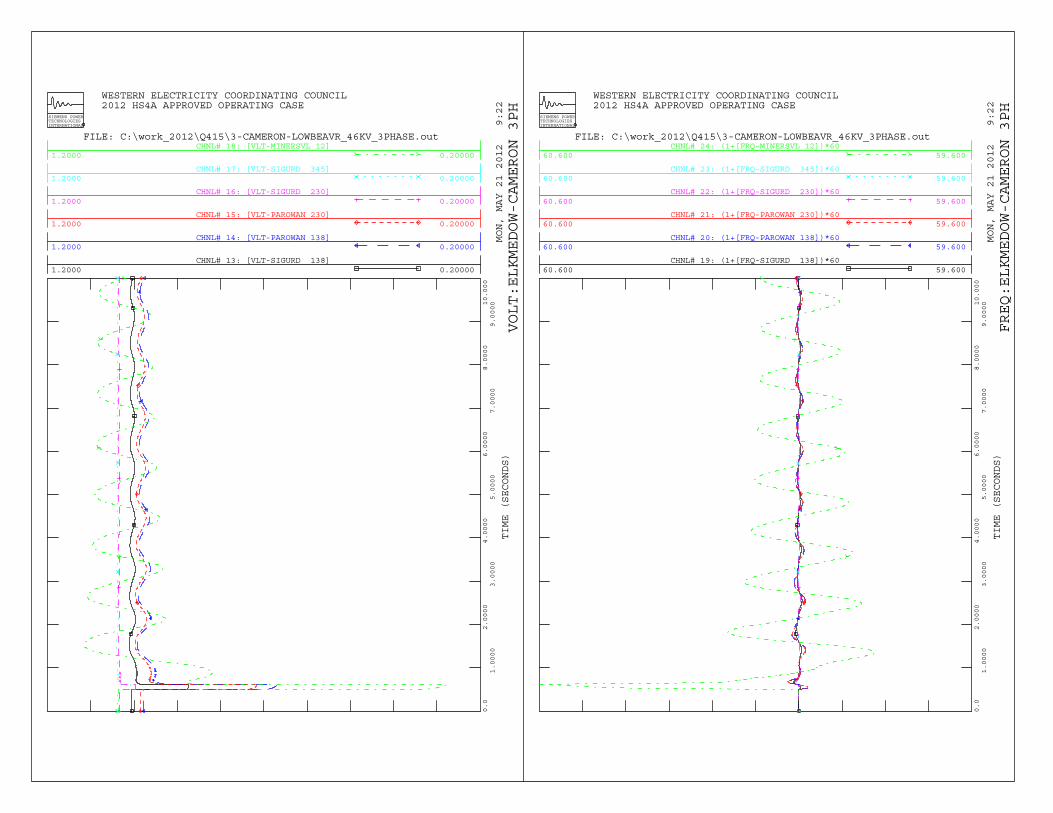
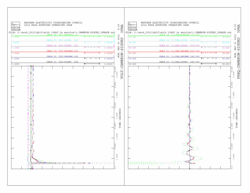
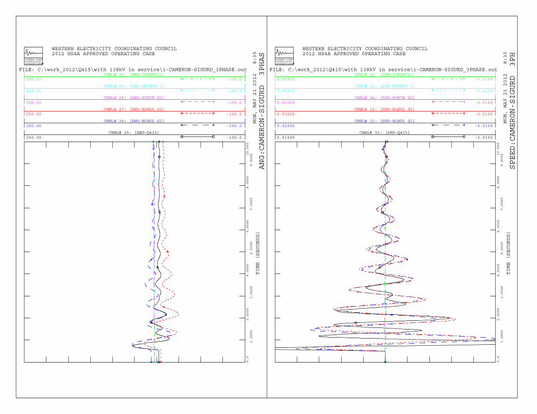
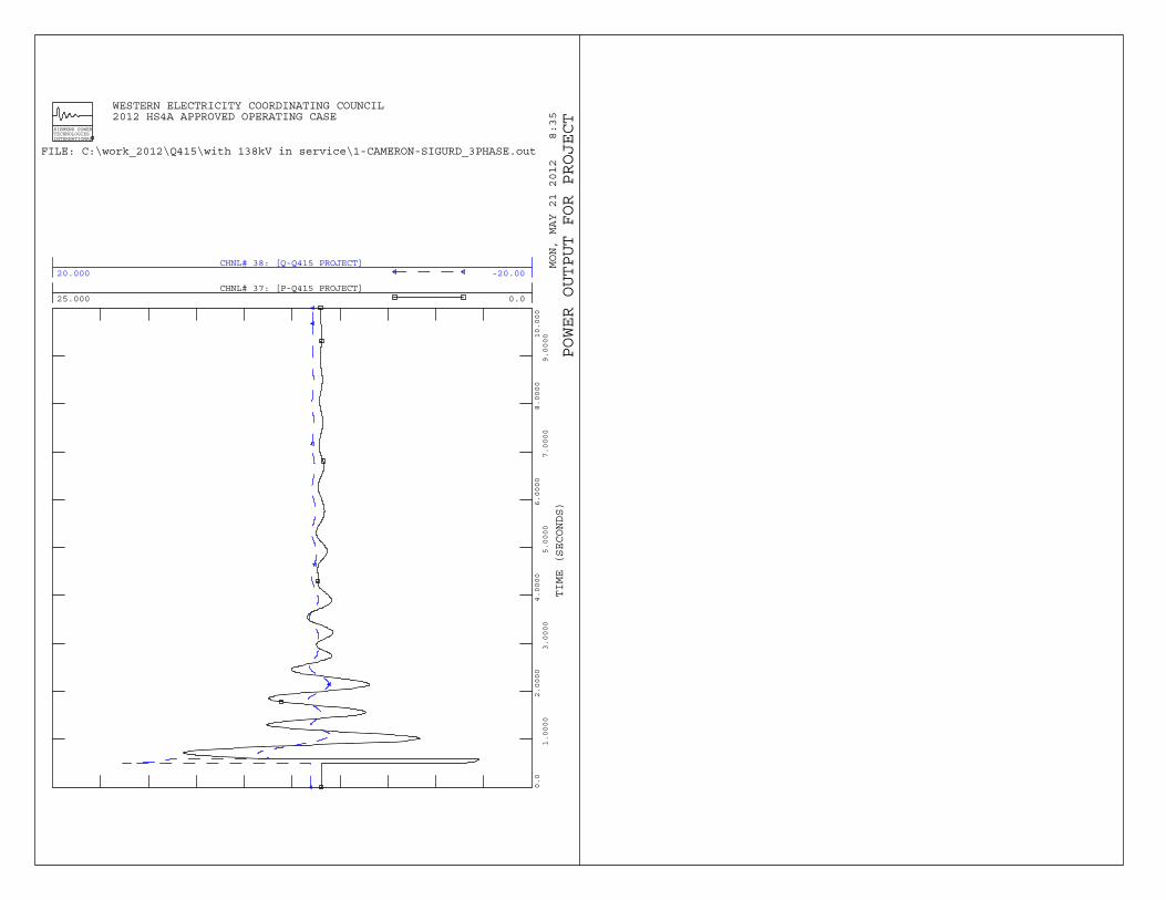
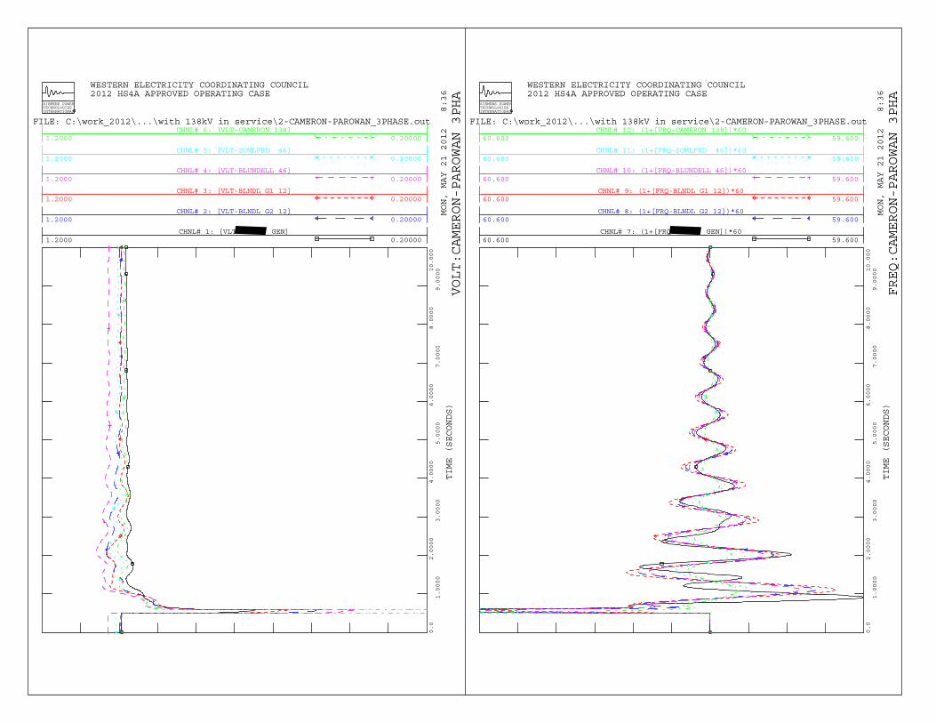
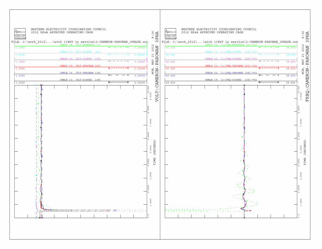
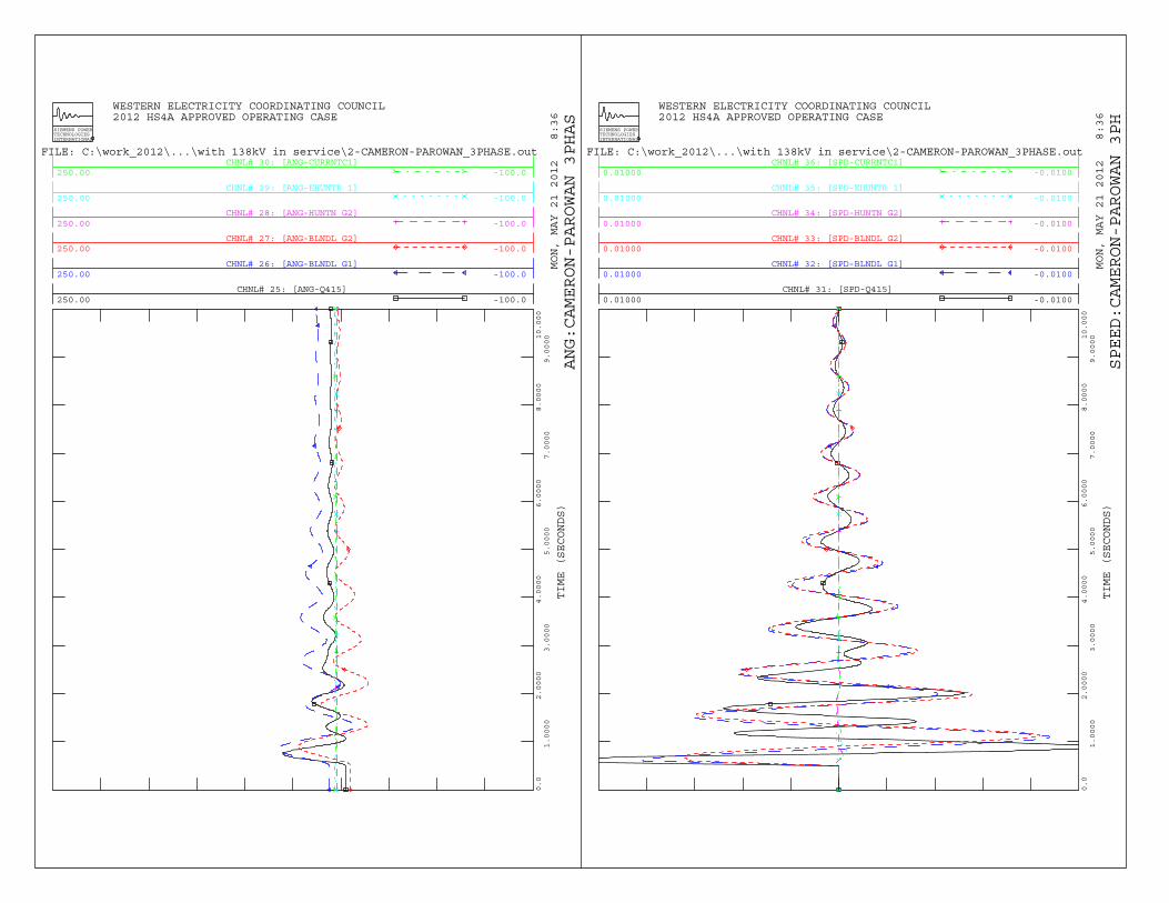
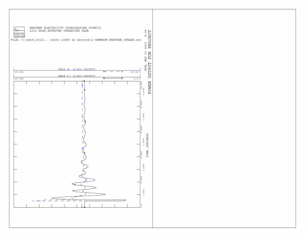
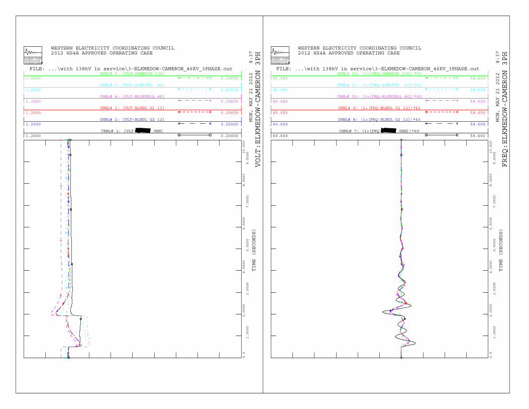
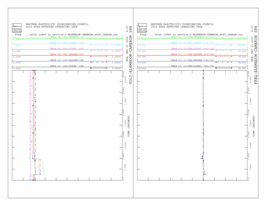
With the future Cameron – Milford 138 kV line open, transient stability analysis identified that the system is stable for loss of the Sigurd – Cameron 138 kV line or Cameron – Parowan 138 kV line, but results in very poor voltage damping for the local area. Transient stability plots are shown in Appendix A. In order to improve damping, a power system stabilizer (PSS) is highly recommended for the new interconnecting generation.
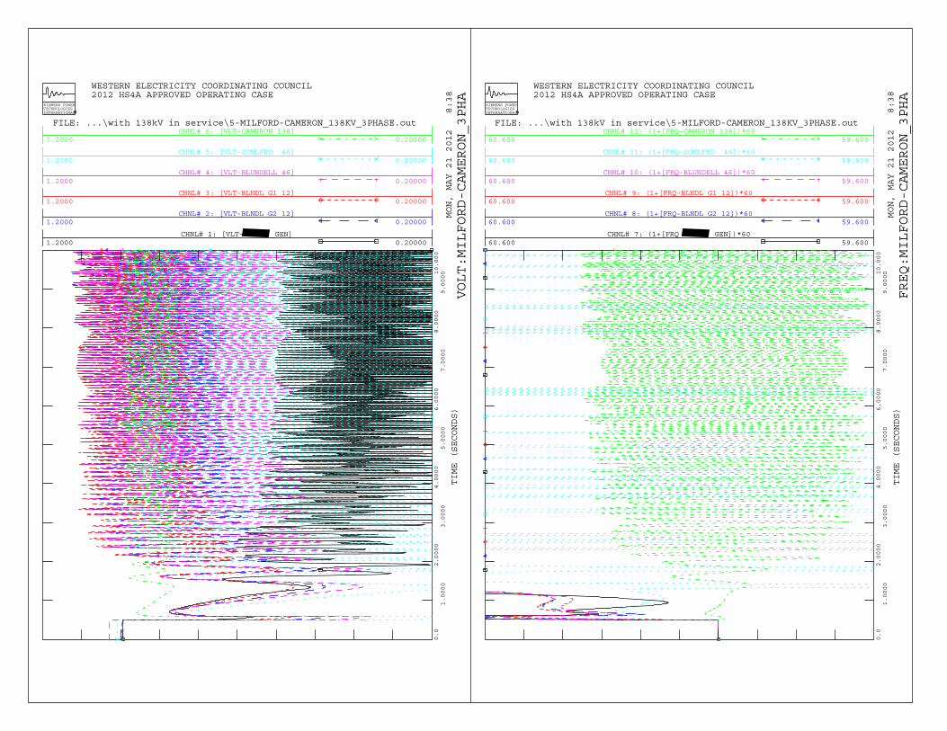
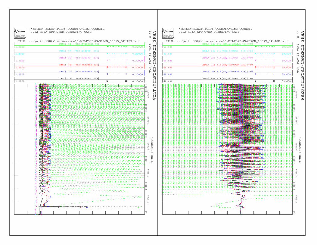
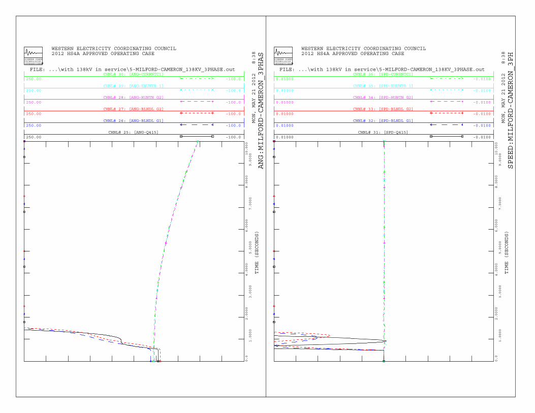
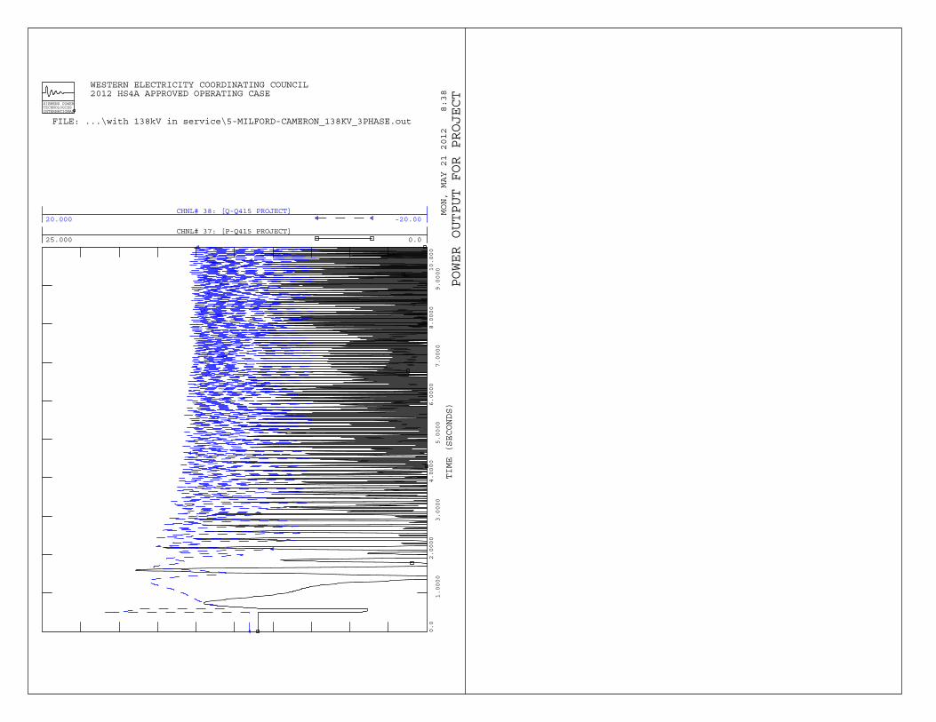
With the Cameron – Parowan 138 kV line closed, loss of the Cameron – Parowan 138 kV line or Sigurd – Cameron 138 kV line results in a better performance. For loss of Cameron – Milford 138 kV line results in local area voltage collapse. Further investigation identified that local area voltage collapse was not caused by the project generation. A local protection scheme needs installed after Cameron – Milford 138 kV line in service to trip Blundell unit #1 for loss of Cameron – Milford 138 kV circuit. Transient stability plots are shown in Appendix B. A summary of contingency performance is provided in the following table. Table 2. List of Contingencies for Transient Stability Analysis
No.
Contingency Description
Stable
Comments
1 Three-phase fault at the Cameron 138 kV bus followed by loss of the Sigurd – Cameron 138 kV circuit (6 cycle).
Yes Poor damping
2 Three-phase fault at the Cameron 138 kV bus followed by loss of the Cameron – Parowan 138 kV circuit (6 cycle).
Yes Poor damping
3 Three-phase fault at Cameron 46 kV bus followed by loss of the Cameron – Low Beaver 46 kV circuit (7 cycle).
Yes Poor damping
4 Three-phase fault at Elk Meadow 46 kV bus followed by loss of the Cameron – Elk Meadow 46 kV circuit (85.8 cycle).
Yes
Cameron – Milford 138 kV line Constructed and Closed
5 Three-phase fault at the Cameron 138 kV bus followed by loss of the Sigurd – Cameron 138 kV circuit (6 cycle).
Yes
6 Three-phase fault at the Cameron 138 kV bus followed by loss of the Cameron – Parowan 138 kV circuit (6 cycle).
Yes
7 Three-phase fault at Elk Meadow 46 kV bus followed by loss of the Cameron – Elk Meadow 46 kV circuit (85.8 cycle).
Yes
8 Three-phase fault at the Milford 138 kV bus followed by loss of the Cameron – Milford 138 kV circuit (6 cycle).
No

3-2
9 Three-phase fault at the Milford 138 kV bus followed by loss of the Cameron – Milford 138 kV circuit (6 cycle) and Blundell units #1 & 2 tripped (16 cycle).
Yes
10 Three-phase fault at the Milford 138 kV bus followed by loss of the Cameron – Milford 138 kV circuit (6 cycle) and Blundell unit #1 tripped (16 cycle).
Yes
11 No fault open Cameron – Milford 138 kV line. No
12 Three-phase fault at the Milford 138 kV bus followed by loss of the Cameron – Milford 138 kV circuit (6 cycle) and Q0162 unit tripped (16 cycles).
No

4-1
4. Conclusions The following conclusions have been reached through this analysis: • The 11 MW geothermal generation interconnecting to the 25-kV circuit (South Milford 21)
out of PacifiCorp’s (“Distribution Provider”) South Milford Substation does not result in transient instability. In addition, the Project will ride through ALL simulated local area contingencies, and it meets the WECC and PacifiCorp transient performance requirement. However, installation of a power system stabilizer (PSS) is highly recommended to improve damping of local voltage oscillations.
• A local protection scheme is require to tripping Blundell unit #1 for loss of Cameron –
Milford 138 kV line (future line). Simulation results are based on data provided by the Interconnection Customer as well as other model data available at the time of the study. Results can be used to help determine whether or not the Project facilities will meet the performance criteria including ride-through requirements which are identified in the Interconnection Agreement, and, in some cases, may indicate that additional equipment is required in order to meet these requirements. However, ultimately it is the Interconnection Customer’s responsibility to meet these requirements during actual operation on a daily basis and failure to do so can result in loss of interconnection privileges. Therefore, results of these simulations should be regarded as informational rather than definitive, and do not relieve the Interconnection Customer of any performance responsibilities. Finally, if the assumptions utilized in this study significantly change, PacifiCorp reserves the right to perform a re-study. Significant changes include, but are not limited to, development of new models which may impact performance as well as changes to the base case assumptions for planned future but as yet uncommitted transmission line and generation facilities.

5-1
5. Appendices A. Cameron – Milford 138 kV line Open (current) B. Cameron – Milford 138 kV line Closed (future)

Appendix A: Cameron – Milford 138kV line Open

Dynamic Simulation Plots Cameron – Sigurd 138 kV line Outage 30 cycles Three Phase fault – Cameron 138kV 36 cycles Clear fault at Cameron, open line Cameron – Sigurd 138 kV line 10 seconds Terminate simulation
A-1
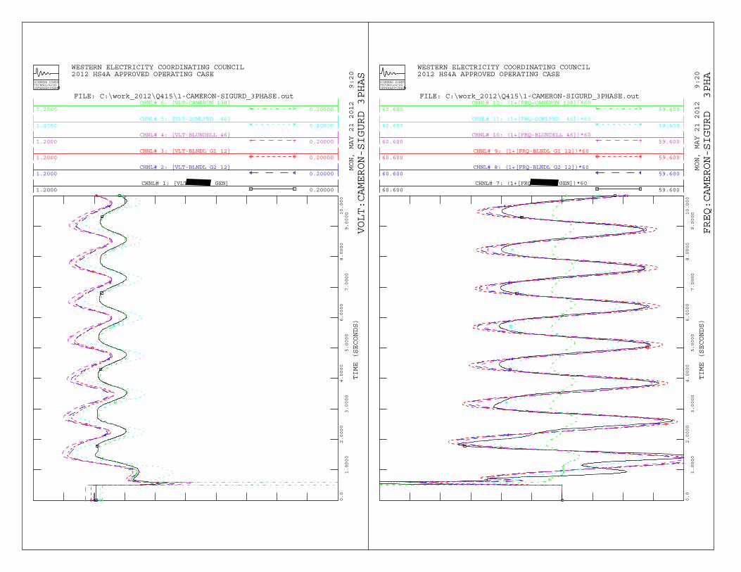
CHNL# 1: [VLT _GEN]1.2000 0.20000
CHNL# 2: [VLT-BLNDL G2 12]1.2000 0.20000
CHNL# 3: [VLT-BLNDL G1 12]1.2000 0.20000
CHNL# 4: [VLT-BLUNDELL 46]1.2000 0.20000
CHNL# 5: [VLT-SOMLFRD 46]1.2000 0.20000
CHNL# 6: [VLT-CAMERON 138]1.2000 0.20000
WESTERN ELECTRICITY COORDINATING COUNCIL 2012 HS4A APPROVED OPERATING CASE
MON, MAY 21 2012 9:20
TIME (SECONDS)
SIEMENS POWERTECHNOLOGIESINTERNATIONAL
0.0
1.0000
2.0000
3.0000
4.0000
5.0000
6.0000
7.0000
8.0000
9.000010.000
FILE: C:\work_2012\Q415\1-CAMERON-SIGURD_3PHASE.out
VOLT:CAMERON-SIGURD 3PHAS
CHNL# 7: (1+[FRQ GEN])*6060.600 59.600
CHNL# 8: (1+[FRQ-BLNDL G2 12])*6060.600 59.600
CHNL# 9: (1+[FRQ-BLNDL G1 12])*6060.600 59.600
CHNL# 10: (1+[FRQ-BLUNDELL 46])*6060.600 59.600
CHNL# 11: (1+[FRQ-SOMLFRD 46])*6060.600 59.600
CHNL# 12: (1+[FRQ-CAMERON 138])*6060.600 59.600
WESTERN ELECTRICITY COORDINATING COUNCIL 2012 HS4A APPROVED OPERATING CASE
MON, MAY 21 2012 9:20
TIME (SECONDS)
SIEMENS POWERTECHNOLOGIESINTERNATIONAL
0.0
1.0000
2.0000
3.0000
4.0000
5.0000
6.0000
7.0000
8.0000
9.000010.000
FILE: C:\work_2012\Q415\1-CAMERON-SIGURD_3PHASE.out
FREQ:CAMERON-SIGURD 3PHA
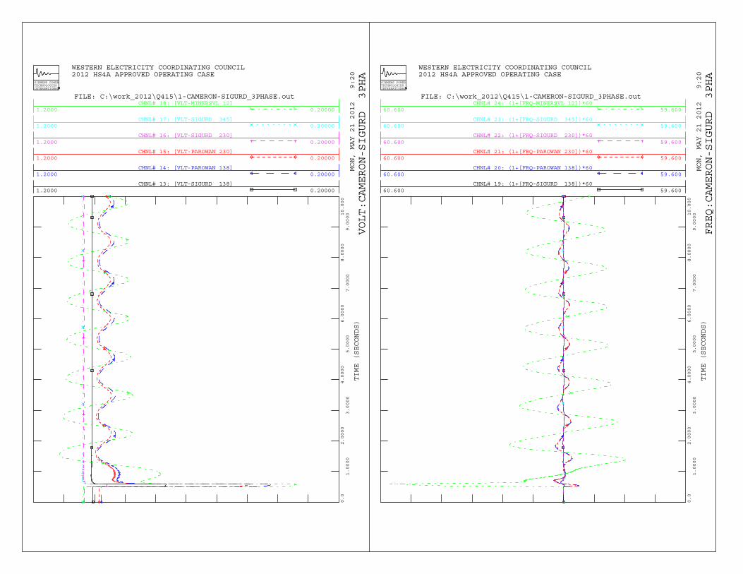
CHNL# 13: [VLT-SIGURD 138]1.2000 0.20000
CHNL# 14: [VLT-PAROWAN 138]1.2000 0.20000
CHNL# 15: [VLT-PAROWAN 230]1.2000 0.20000
CHNL# 16: [VLT-SIGURD 230]1.2000 0.20000
CHNL# 17: [VLT-SIGURD 345]1.2000 0.20000
CHNL# 18: [VLT-MINERSVL 12]1.2000 0.20000
WESTERN ELECTRICITY COORDINATING COUNCIL 2012 HS4A APPROVED OPERATING CASE
MON, MAY 21 2012 9:20
TIME (SECONDS)
SIEMENS POWERTECHNOLOGIESINTERNATIONAL
0.0
1.0000
2.0000
3.0000
4.0000
5.0000
6.0000
7.0000
8.0000
9.000010.000
FILE: C:\work_2012\Q415\1-CAMERON-SIGURD_3PHASE.out
VOLT:CAMERON-SIGURD 3PHA
CHNL# 19: (1+[FRQ-SIGURD 138])*6060.600 59.600
CHNL# 20: (1+[FRQ-PAROWAN 138])*6060.600 59.600
CHNL# 21: (1+[FRQ-PAROWAN 230])*6060.600 59.600
CHNL# 22: (1+[FRQ-SIGURD 230])*6060.600 59.600
CHNL# 23: (1+[FRQ-SIGURD 345])*6060.600 59.600
CHNL# 24: (1+[FRQ-MINERSVL 12])*6060.600 59.600
WESTERN ELECTRICITY COORDINATING COUNCIL 2012 HS4A APPROVED OPERATING CASE
MON, MAY 21 2012 9:20
TIME (SECONDS)
SIEMENS POWERTECHNOLOGIESINTERNATIONAL
0.0
1.0000
2.0000
3.0000
4.0000
5.0000
6.0000
7.0000
8.0000
9.000010.000
FILE: C:\work_2012\Q415\1-CAMERON-SIGURD_3PHASE.out
FREQ:CAMERON-SIGURD 3PHA
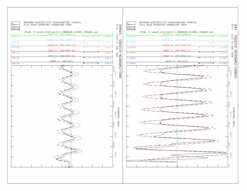
CHNL# 25: [ANG-Q415]250.00 -100.0
CHNL# 26: [ANG-BLNDL G1]250.00 -100.0
CHNL# 27: [ANG-BLNDL G2]250.00 -100.0
CHNL# 28: [ANG-HUNTN G2]250.00 -100.0
CHNL# 29: [ANG-EHUNTR 1]250.00 -100.0
CHNL# 30: [ANG-CURRNTC1]250.00 -100.0
WESTERN ELECTRICITY COORDINATING COUNCIL 2012 HS4A APPROVED OPERATING CASE
MON, MAY 21 2012 9:20
TIME (SECONDS)
SIEMENS POWERTECHNOLOGIESINTERNATIONAL
0.0
1.0000
2.0000
3.0000
4.0000
5.0000
6.0000
7.0000
8.0000
9.000010.000
FILE: C:\work_2012\Q415\1-CAMERON-SIGURD_3PHASE.out
ANG:CAMERON-SIGURD 3PHAS
CHNL# 31: [SPD-Q415]0.01000 -0.0100
CHNL# 32: [SPD-BLNDL G1]0.01000 -0.0100
CHNL# 33: [SPD-BLNDL G2]0.01000 -0.0100
CHNL# 34: [SPD-HUNTN G2]0.01000 -0.0100
CHNL# 35: [SPD-EHUNTR 1]0.01000 -0.0100
CHNL# 36: [SPD-CURRNTC1]0.01000 -0.0100
WESTERN ELECTRICITY COORDINATING COUNCIL 2012 HS4A APPROVED OPERATING CASE
MON, MAY 21 2012 9:20
TIME (SECONDS)
SIEMENS POWERTECHNOLOGIESINTERNATIONAL
0.0
1.0000
2.0000
3.0000
4.0000
5.0000
6.0000
7.0000
8.0000
9.000010.000
FILE: C:\work_2012\Q415\1-CAMERON-SIGURD_3PHASE.out
SPEED:CAMERON-SIGURD 3PH

CHNL# 37: [P-Q415 PROJECT]25.000 0.0
CHNL# 38: [Q-Q415 PROJECT]20.000 -20.00
WESTERN ELECTRICITY COORDINATING COUNCIL 2012 HS4A APPROVED OPERATING CASE
MON, MAY 21 2012 9:20
TIME (SECONDS)
SIEMENS POWERTECHNOLOGIESINTERNATIONAL
0.0
1.0000
2.0000
3.0000
4.0000
5.0000
6.0000
7.0000
8.0000
9.000010.000
FILE: C:\work_2012\Q415\1-CAMERON-SIGURD_3PHASE.out
POWER OUTPUT FOR PROJECT

Dynamic Simulation Plots Cameron – Parowan 138 kV line Outage 30 cycles Three Phase fault – Cameron 138kV 36 cycles Clear fault at Cameron, open line Cameron – Parowan 138 kV line 10 seconds Terminate simulation
A-1

CHNL# 1: [VLT _GEN]1.2000 0.20000
CHNL# 2: [VLT-BLNDL G2 12]1.2000 0.20000
CHNL# 3: [VLT-BLNDL G1 12]1.2000 0.20000
CHNL# 4: [VLT-BLUNDELL 46]1.2000 0.20000
CHNL# 5: [VLT-SOMLFRD 46]1.2000 0.20000
CHNL# 6: [VLT-CAMERON 138]1.2000 0.20000
WESTERN ELECTRICITY COORDINATING COUNCIL 2012 HS4A APPROVED OPERATING CASE
MON, MAY 21 2012 9:21
TIME (SECONDS)
SIEMENS POWERTECHNOLOGIESINTERNATIONAL
0.0
1.0000
2.0000
3.0000
4.0000
5.0000
6.0000
7.0000
8.0000
9.000010.000
FILE: C:\work_2012\Q415\2-CAMERON-PAROWAN_3PHASE.out
VOLT:CAMERON-PAROWAN 3PHA
CHNL# 7: (1+[FRQ _GEN])*6060.600 59.600
CHNL# 8: (1+[FRQ-BLNDL G2 12])*6060.600 59.600
CHNL# 9: (1+[FRQ-BLNDL G1 12])*6060.600 59.600
CHNL# 10: (1+[FRQ-BLUNDELL 46])*6060.600 59.600
CHNL# 11: (1+[FRQ-SOMLFRD 46])*6060.600 59.600
CHNL# 12: (1+[FRQ-CAMERON 138])*6060.600 59.600
WESTERN ELECTRICITY COORDINATING COUNCIL 2012 HS4A APPROVED OPERATING CASE
MON, MAY 21 2012 9:21
TIME (SECONDS)
SIEMENS POWERTECHNOLOGIESINTERNATIONAL
0.0
1.0000
2.0000
3.0000
4.0000
5.0000
6.0000
7.0000
8.0000
9.000010.000
FILE: C:\work_2012\Q415\2-CAMERON-PAROWAN_3PHASE.out
FREQ:CAMERON-PAROWAN 3PHA
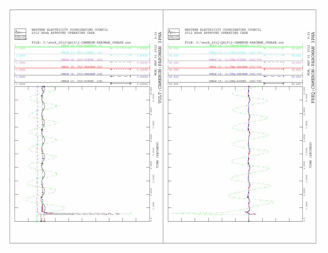
CHNL# 13: [VLT-SIGURD 138]1.2000 0.20000
CHNL# 14: [VLT-PAROWAN 138]1.2000 0.20000
CHNL# 15: [VLT-PAROWAN 230]1.2000 0.20000
CHNL# 16: [VLT-SIGURD 230]1.2000 0.20000
CHNL# 17: [VLT-SIGURD 345]1.2000 0.20000
CHNL# 18: [VLT-MINERSVL 12]1.2000 0.20000
WESTERN ELECTRICITY COORDINATING COUNCIL 2012 HS4A APPROVED OPERATING CASE
MON, MAY 21 2012 9:21
TIME (SECONDS)
SIEMENS POWERTECHNOLOGIESINTERNATIONAL
0.0
1.0000
2.0000
3.0000
4.0000
5.0000
6.0000
7.0000
8.0000
9.000010.000
FILE: C:\work_2012\Q415\2-CAMERON-PAROWAN_3PHASE.out
VOLT:CAMERON-PAROWAN 3PHA
CHNL# 19: (1+[FRQ-SIGURD 138])*6060.600 59.600
CHNL# 20: (1+[FRQ-PAROWAN 138])*6060.600 59.600
CHNL# 21: (1+[FRQ-PAROWAN 230])*6060.600 59.600
CHNL# 22: (1+[FRQ-SIGURD 230])*6060.600 59.600
CHNL# 23: (1+[FRQ-SIGURD 345])*6060.600 59.600
CHNL# 24: (1+[FRQ-MINERSVL 12])*6060.600 59.600
WESTERN ELECTRICITY COORDINATING COUNCIL 2012 HS4A APPROVED OPERATING CASE
MON, MAY 21 2012 9:21
TIME (SECONDS)
SIEMENS POWERTECHNOLOGIESINTERNATIONAL
0.0
1.0000
2.0000
3.0000
4.0000
5.0000
6.0000
7.0000
8.0000
9.000010.000
FILE: C:\work_2012\Q415\2-CAMERON-PAROWAN_3PHASE.out
FREQ:CAMERON-PAROWAN 3PHA
CHNL# 25: [ANG-Q415]250.00 -100.0
CHNL# 26: [ANG-BLNDL G1]250.00 -100.0
CHNL# 27: [ANG-BLNDL G2]250.00 -100.0
CHNL# 28: [ANG-HUNTN G2]250.00 -100.0
CHNL# 29: [ANG-EHUNTR 1]250.00 -100.0
CHNL# 30: [ANG-CURRNTC1]250.00 -100.0
WESTERN ELECTRICITY COORDINATING COUNCIL 2012 HS4A APPROVED OPERATING CASE
MON, MAY 21 2012 9:21
TIME (SECONDS)
SIEMENS POWERTECHNOLOGIESINTERNATIONAL
0.0
1.0000
2.0000
3.0000
4.0000
5.0000
6.0000
7.0000
8.0000
9.000010.000
FILE: C:\work_2012\Q415\2-CAMERON-PAROWAN_3PHASE.out
ANG:CAMERON-PAROWAN 3PHAS
CHNL# 31: [SPD-Q415]0.01000 -0.0100
CHNL# 32: [SPD-BLNDL G1]0.01000 -0.0100
CHNL# 33: [SPD-BLNDL G2]0.01000 -0.0100
CHNL# 34: [SPD-HUNTN G2]0.01000 -0.0100
CHNL# 35: [SPD-EHUNTR 1]0.01000 -0.0100
CHNL# 36: [SPD-CURRNTC1]0.01000 -0.0100
WESTERN ELECTRICITY COORDINATING COUNCIL 2012 HS4A APPROVED OPERATING CASE
MON, MAY 21 2012 9:21
TIME (SECONDS)
SIEMENS POWERTECHNOLOGIESINTERNATIONAL
0.0
1.0000
2.0000
3.0000
4.0000
5.0000
6.0000
7.0000
8.0000
9.000010.000
FILE: C:\work_2012\Q415\2-CAMERON-PAROWAN_3PHASE.out
SPEED:CAMERON-PAROWAN 3PH
CHNL# 37: [P-Q415 PROJECT]25.000 0.0
CHNL# 38: [Q-Q415 PROJECT]20.000 -20.00
WESTERN ELECTRICITY COORDINATING COUNCIL 2012 HS4A APPROVED OPERATING CASE
MON, MAY 21 2012 9:21
TIME (SECONDS)
SIEMENS POWERTECHNOLOGIESINTERNATIONAL
0.0
1.0000
2.0000
3.0000
4.0000
5.0000
6.0000
7.0000
8.0000
9.000010.000
FILE: C:\work_2012\Q415\2-CAMERON-PAROWAN_3PHASE.out
POWER OUTPUT FOR PROJECT

Dynamic Simulation Plots
Cameron – Low Beaver 46 kV line Outage 30 cycles Three Phase fault – Cameron 46kV 37 cycles Clear fault at Cameron, open line Cameron – Low Beaver 46 kV line 10 seconds Terminate simulation
A-1
CHNL# 1: [VLT- _GEN]1.2000 0.20000
CHNL# 2: [VLT-BLNDL G2 12]1.2000 0.20000
CHNL# 3: [VLT-BLNDL G1 12]1.2000 0.20000
CHNL# 4: [VLT-BLUNDELL 46]1.2000 0.20000
CHNL# 5: [VLT-SOMLFRD 46]1.2000 0.20000
CHNL# 6: [VLT-CAMERON 138]1.2000 0.20000
WESTERN ELECTRICITY COORDINATING COUNCIL 2012 HS4A APPROVED OPERATING CASE
MON, MAY 21 2012 9:22
TIME (SECONDS)
SIEMENS POWERTECHNOLOGIESINTERNATIONAL
0.0
1.0000
2.0000
3.0000
4.0000
5.0000
6.0000
7.0000
8.0000
9.000010.000
FILE: C:\work_2012\Q415\3-CAMERON-LOWBEAVR_46KV_3PHASE.out
VOLT:ELKMEDOW-CAMERON 3PH
CHNL# 7: (1+[FRQ _GEN])*6060.600 59.600
CHNL# 8: (1+[FRQ-BLNDL G2 12])*6060.600 59.600
CHNL# 9: (1+[FRQ-BLNDL G1 12])*6060.600 59.600
CHNL# 10: (1+[FRQ-BLUNDELL 46])*6060.600 59.600
CHNL# 11: (1+[FRQ-SOMLFRD 46])*6060.600 59.600
CHNL# 12: (1+[FRQ-CAMERON 138])*6060.600 59.600
WESTERN ELECTRICITY COORDINATING COUNCIL 2012 HS4A APPROVED OPERATING CASE
MON, MAY 21 2012 9:22
TIME (SECONDS)
SIEMENS POWERTECHNOLOGIESINTERNATIONAL
0.0
1.0000
2.0000
3.0000
4.0000
5.0000
6.0000
7.0000
8.0000
9.000010.000
FILE: C:\work_2012\Q415\3-CAMERON-LOWBEAVR_46KV_3PHASE.out
FREQ:ELKMEDOW-CAMERON 3PH
CHNL# 13: [VLT-SIGURD 138]1.2000 0.20000
CHNL# 14: [VLT-PAROWAN 138]1.2000 0.20000
CHNL# 15: [VLT-PAROWAN 230]1.2000 0.20000
CHNL# 16: [VLT-SIGURD 230]1.2000 0.20000
CHNL# 17: [VLT-SIGURD 345]1.2000 0.20000
CHNL# 18: [VLT-MINERSVL 12]1.2000 0.20000
WESTERN ELECTRICITY COORDINATING COUNCIL 2012 HS4A APPROVED OPERATING CASE
MON, MAY 21 2012 9:22
TIME (SECONDS)
SIEMENS POWERTECHNOLOGIESINTERNATIONAL
0.0
1.0000
2.0000
3.0000
4.0000
5.0000
6.0000
7.0000
8.0000
9.000010.000
FILE: C:\work_2012\Q415\3-CAMERON-LOWBEAVR_46KV_3PHASE.out
VOLT:ELKMEDOW-CAMERON 3PH
CHNL# 19: (1+[FRQ-SIGURD 138])*6060.600 59.600
CHNL# 20: (1+[FRQ-PAROWAN 138])*6060.600 59.600
CHNL# 21: (1+[FRQ-PAROWAN 230])*6060.600 59.600
CHNL# 22: (1+[FRQ-SIGURD 230])*6060.600 59.600
CHNL# 23: (1+[FRQ-SIGURD 345])*6060.600 59.600
CHNL# 24: (1+[FRQ-MINERSVL 12])*6060.600 59.600
WESTERN ELECTRICITY COORDINATING COUNCIL 2012 HS4A APPROVED OPERATING CASE
MON, MAY 21 2012 9:22
TIME (SECONDS)
SIEMENS POWERTECHNOLOGIESINTERNATIONAL
0.0
1.0000
2.0000
3.0000
4.0000
5.0000
6.0000
7.0000
8.0000
9.000010.000
FILE: C:\work_2012\Q415\3-CAMERON-LOWBEAVR_46KV_3PHASE.out
FREQ:ELKMEDOW-CAMERON 3PH

CHNL# 25: [ANG-Q415]250.00 -100.0
CHNL# 26: [ANG-BLNDL G1]250.00 -100.0
CHNL# 27: [ANG-BLNDL G2]250.00 -100.0
CHNL# 28: [ANG-HUNTN G2]250.00 -100.0
CHNL# 29: [ANG-EHUNTR 1]250.00 -100.0
CHNL# 30: [ANG-CURRNTC1]250.00 -100.0
WESTERN ELECTRICITY COORDINATING COUNCIL 2012 HS4A APPROVED OPERATING CASE
MON, MAY 21 2012 9:22
TIME (SECONDS)
SIEMENS POWERTECHNOLOGIESINTERNATIONAL
0.0
1.0000
2.0000
3.0000
4.0000
5.0000
6.0000
7.0000
8.0000
9.000010.000
FILE: C:\work_2012\Q415\3-CAMERON-LOWBEAVR_46KV_3PHASE.out
ANG:ELKMEDOW-CAMERON 3PHA
CHNL# 31: [SPD-Q415]0.01000 -0.0100
CHNL# 32: [SPD-BLNDL G1]0.01000 -0.0100
CHNL# 33: [SPD-BLNDL G2]0.01000 -0.0100
CHNL# 34: [SPD-HUNTN G2]0.01000 -0.0100
CHNL# 35: [SPD-EHUNTR 1]0.01000 -0.0100
CHNL# 36: [SPD-CURRNTC1]0.01000 -0.0100
WESTERN ELECTRICITY COORDINATING COUNCIL 2012 HS4A APPROVED OPERATING CASE
MON, MAY 21 2012 9:22
TIME (SECONDS)
SIEMENS POWERTECHNOLOGIESINTERNATIONAL
0.0
1.0000
2.0000
3.0000
4.0000
5.0000
6.0000
7.0000
8.0000
9.000010.000
FILE: C:\work_2012\Q415\3-CAMERON-LOWBEAVR_46KV_3PHASE.out
SPEED:ELKMEDOW-CAMERON 3P
CHNL# 37: [P-Q415 PROJECT]25.000 0.0
CHNL# 38: [Q-Q415 PROJECT]20.000 -20.00
WESTERN ELECTRICITY COORDINATING COUNCIL 2012 HS4A APPROVED OPERATING CASE
MON, MAY 21 2012 9:22
TIME (SECONDS)
SIEMENS POWERTECHNOLOGIESINTERNATIONAL
0.0
1.0000
2.0000
3.0000
4.0000
5.0000
6.0000
7.0000
8.0000
9.000010.000
FILE: C:\work_2012\Q415\3-CAMERON-LOWBEAVR_46KV_3PHASE.out
POWER OUTPUT FOR PROJECT

A-1
Dynamic Simulation Plots Elk Meadow - Cameron 46 kV line Outage 30 cycles Three Phase fault – Elk Meadow 46kV 115.8 cycles Clear fault at Elk Meadow, open line Cameron – Elk Meadow 46 kV line 10 seconds Terminate simulation

CHNL# 1: [VLT- _GEN]1.2000 0.20000
CHNL# 2: [VLT-BLNDL G2 12]1.2000 0.20000
CHNL# 3: [VLT-BLNDL G1 12]1.2000 0.20000
CHNL# 4: [VLT-BLUNDELL 46]1.2000 0.20000
CHNL# 5: [VLT-SOMLFRD 46]1.2000 0.20000
CHNL# 6: [VLT-CAMERON 138]1.2000 0.20000
WESTERN ELECTRICITY COORDINATING COUNCIL 2012 HS4A APPROVED OPERATING CASE
MON, MAY 21 2012 9:23
TIME (SECONDS)
SIEMENS POWERTECHNOLOGIESINTERNATIONAL
0.0
1.0000
2.0000
3.0000
4.0000
5.0000
6.0000
7.0000
8.0000
9.000010.000
FILE: C:\work_2012\Q415\3-ELKMEDOW-CAMERON_46KV_3PHASE.out
VOLT:ELKMEDOW-CAMERON 3PH
CHNL# 7: (1+[FRQ _GEN])*6060.600 59.600
CHNL# 8: (1+[FRQ-BLNDL G2 12])*6060.600 59.600
CHNL# 9: (1+[FRQ-BLNDL G1 12])*6060.600 59.600
CHNL# 10: (1+[FRQ-BLUNDELL 46])*6060.600 59.600
CHNL# 11: (1+[FRQ-SOMLFRD 46])*6060.600 59.600
CHNL# 12: (1+[FRQ-CAMERON 138])*6060.600 59.600
WESTERN ELECTRICITY COORDINATING COUNCIL 2012 HS4A APPROVED OPERATING CASE
MON, MAY 21 2012 9:23
TIME (SECONDS)
SIEMENS POWERTECHNOLOGIESINTERNATIONAL
0.0
1.0000
2.0000
3.0000
4.0000
5.0000
6.0000
7.0000
8.0000
9.000010.000
FILE: C:\work_2012\Q415\3-ELKMEDOW-CAMERON_46KV_3PHASE.out
FREQ:ELKMEDOW-CAMERON 3PH
CHNL# 13: [VLT-SIGURD 138]1.2000 0.20000
CHNL# 14: [VLT-PAROWAN 138]1.2000 0.20000
CHNL# 15: [VLT-PAROWAN 230]1.2000 0.20000
CHNL# 16: [VLT-SIGURD 230]1.2000 0.20000
CHNL# 17: [VLT-SIGURD 345]1.2000 0.20000
CHNL# 18: [VLT-MINERSVL 12]1.2000 0.20000
WESTERN ELECTRICITY COORDINATING COUNCIL 2012 HS4A APPROVED OPERATING CASE
MON, MAY 21 2012 9:23
TIME (SECONDS)
SIEMENS POWERTECHNOLOGIESINTERNATIONAL
0.0
1.0000
2.0000
3.0000
4.0000
5.0000
6.0000
7.0000
8.0000
9.000010.000
FILE: C:\work_2012\Q415\3-ELKMEDOW-CAMERON_46KV_3PHASE.out
VOLT:ELKMEDOW-CAMERON 3PH
CHNL# 19: (1+[FRQ-SIGURD 138])*6060.600 59.600
CHNL# 20: (1+[FRQ-PAROWAN 138])*6060.600 59.600
CHNL# 21: (1+[FRQ-PAROWAN 230])*6060.600 59.600
CHNL# 22: (1+[FRQ-SIGURD 230])*6060.600 59.600
CHNL# 23: (1+[FRQ-SIGURD 345])*6060.600 59.600
CHNL# 24: (1+[FRQ-MINERSVL 12])*6060.600 59.600
WESTERN ELECTRICITY COORDINATING COUNCIL 2012 HS4A APPROVED OPERATING CASE
MON, MAY 21 2012 9:23
TIME (SECONDS)
SIEMENS POWERTECHNOLOGIESINTERNATIONAL
0.0
1.0000
2.0000
3.0000
4.0000
5.0000
6.0000
7.0000
8.0000
9.000010.000
FILE: C:\work_2012\Q415\3-ELKMEDOW-CAMERON_46KV_3PHASE.out
FREQ:ELKMEDOW-CAMERON 3PH
CHNL# 25: [ANG-Q415]250.00 -100.0
CHNL# 26: [ANG-BLNDL G1]250.00 -100.0
CHNL# 27: [ANG-BLNDL G2]250.00 -100.0
CHNL# 28: [ANG-HUNTN G2]250.00 -100.0
CHNL# 29: [ANG-EHUNTR 1]250.00 -100.0
CHNL# 30: [ANG-CURRNTC1]250.00 -100.0
WESTERN ELECTRICITY COORDINATING COUNCIL 2012 HS4A APPROVED OPERATING CASE
MON, MAY 21 2012 9:23
TIME (SECONDS)
SIEMENS POWERTECHNOLOGIESINTERNATIONAL
0.0
1.0000
2.0000
3.0000
4.0000
5.0000
6.0000
7.0000
8.0000
9.000010.000
FILE: C:\work_2012\Q415\3-ELKMEDOW-CAMERON_46KV_3PHASE.out
ANG:ELKMEDOW-CAMERON 3PHA
CHNL# 31: [SPD-Q415]0.01000 -0.0100
CHNL# 32: [SPD-BLNDL G1]0.01000 -0.0100
CHNL# 33: [SPD-BLNDL G2]0.01000 -0.0100
CHNL# 34: [SPD-HUNTN G2]0.01000 -0.0100
CHNL# 35: [SPD-EHUNTR 1]0.01000 -0.0100
CHNL# 36: [SPD-CURRNTC1]0.01000 -0.0100
WESTERN ELECTRICITY COORDINATING COUNCIL 2012 HS4A APPROVED OPERATING CASE
MON, MAY 21 2012 9:23
TIME (SECONDS)
SIEMENS POWERTECHNOLOGIESINTERNATIONAL
0.0
1.0000
2.0000
3.0000
4.0000
5.0000
6.0000
7.0000
8.0000
9.000010.000
FILE: C:\work_2012\Q415\3-ELKMEDOW-CAMERON_46KV_3PHASE.out
SPEED:ELKMEDOW-CAMERON 3P

CHNL# 37: [P-Q415 PROJECT]25.000 0.0
CHNL# 38: [Q-Q415 PROJECT]20.000 -20.00
WESTERN ELECTRICITY COORDINATING COUNCIL 2012 HS4A APPROVED OPERATING CASE
MON, MAY 21 2012 9:23
TIME (SECONDS)
SIEMENS POWERTECHNOLOGIESINTERNATIONAL
0.0
1.0000
2.0000
3.0000
4.0000
5.0000
6.0000
7.0000
8.0000
9.000010.000
FILE: C:\work_2012\Q415\3-ELKMEDOW-CAMERON_46KV_3PHASE.out
POWER OUTPUT FOR PROJECT

Appendix B: Cameron – Milford 138 kV line Closed
B-1

Dynamic Simulation Plots Cameron – Sigurd 138 kV line Outage 30 cycles Three Phase fault – Cameron 138kV 36 cycles Clear fault at Cameron, open line Cameron – Sigurd 138 kV line 10 seconds Terminate simulation
B-2

CHNL# 1: [VLT- _GEN]1.2000 0.20000
CHNL# 2: [VLT-BLNDL G2 12]1.2000 0.20000
CHNL# 3: [VLT-BLNDL G1 12]1.2000 0.20000
CHNL# 4: [VLT-BLUNDELL 46]1.2000 0.20000
CHNL# 5: [VLT-SOMLFRD 46]1.2000 0.20000
CHNL# 6: [VLT-CAMERON 138]1.2000 0.20000
WESTERN ELECTRICITY COORDINATING COUNCIL 2012 HS4A APPROVED OPERATING CASE
MON, MAY 21 2012 8:35
TIME (SECONDS)
SIEMENS POWERTECHNOLOGIESINTERNATIONAL
0.0
1.0000
2.0000
3.0000
4.0000
5.0000
6.0000
7.0000
8.0000
9.000010.000
FILE: C:\work_2012\Q415\with 138kV in service\1-CAMERON-SIGURD_3PHASE.out
VOLT:CAMERON-SIGURD 3PHAS
CHNL# 7: (1+[FRQ _GEN])*6060.600 59.600
CHNL# 8: (1+[FRQ-BLNDL G2 12])*6060.600 59.600
CHNL# 9: (1+[FRQ-BLNDL G1 12])*6060.600 59.600
CHNL# 10: (1+[FRQ-BLUNDELL 46])*6060.600 59.600
CHNL# 11: (1+[FRQ-SOMLFRD 46])*6060.600 59.600
CHNL# 12: (1+[FRQ-CAMERON 138])*6060.600 59.600
WESTERN ELECTRICITY COORDINATING COUNCIL 2012 HS4A APPROVED OPERATING CASE
MON, MAY 21 2012 8:35
TIME (SECONDS)
SIEMENS POWERTECHNOLOGIESINTERNATIONAL
0.0
1.0000
2.0000
3.0000
4.0000
5.0000
6.0000
7.0000
8.0000
9.000010.000
FILE: C:\work_2012\Q415\with 138kV in service\1-CAMERON-SIGURD_3PHASE.out
FREQ:CAMERON-SIGURD 3PHA
CHNL# 13: [VLT-SIGURD 138]1.2000 0.20000
CHNL# 14: [VLT-PAROWAN 138]1.2000 0.20000
CHNL# 15: [VLT-PAROWAN 230]1.2000 0.20000
CHNL# 16: [VLT-SIGURD 230]1.2000 0.20000
CHNL# 17: [VLT-SIGURD 345]1.2000 0.20000
CHNL# 18: [VLT-MINERSVL 12]1.2000 0.20000
WESTERN ELECTRICITY COORDINATING COUNCIL 2012 HS4A APPROVED OPERATING CASE
MON, MAY 21 2012 8:35
TIME (SECONDS)
SIEMENS POWERTECHNOLOGIESINTERNATIONAL
0.0
1.0000
2.0000
3.0000
4.0000
5.0000
6.0000
7.0000
8.0000
9.000010.000
FILE: C:\work_2012\Q415\with 138kV in service\1-CAMERON-SIGURD_3PHASE.out
VOLT:CAMERON-SIGURD 3PHA
CHNL# 19: (1+[FRQ-SIGURD 138])*6060.600 59.600
CHNL# 20: (1+[FRQ-PAROWAN 138])*6060.600 59.600
CHNL# 21: (1+[FRQ-PAROWAN 230])*6060.600 59.600
CHNL# 22: (1+[FRQ-SIGURD 230])*6060.600 59.600
CHNL# 23: (1+[FRQ-SIGURD 345])*6060.600 59.600
CHNL# 24: (1+[FRQ-MINERSVL 12])*6060.600 59.600
WESTERN ELECTRICITY COORDINATING COUNCIL 2012 HS4A APPROVED OPERATING CASE
MON, MAY 21 2012 8:35
TIME (SECONDS)
SIEMENS POWERTECHNOLOGIESINTERNATIONAL
0.0
1.0000
2.0000
3.0000
4.0000
5.0000
6.0000
7.0000
8.0000
9.000010.000
FILE: C:\work_2012\Q415\with 138kV in service\1-CAMERON-SIGURD_3PHASE.out
FREQ:CAMERON-SIGURD 3PHA
CHNL# 25: [ANG-Q415]250.00 -100.0
CHNL# 26: [ANG-BLNDL G1]250.00 -100.0
CHNL# 27: [ANG-BLNDL G2]250.00 -100.0
CHNL# 28: [ANG-HUNTN G2]250.00 -100.0
CHNL# 29: [ANG-EHUNTR 1]250.00 -100.0
CHNL# 30: [ANG-CURRNTC1]250.00 -100.0
WESTERN ELECTRICITY COORDINATING COUNCIL 2012 HS4A APPROVED OPERATING CASE
MON, MAY 21 2012 8:35
TIME (SECONDS)
SIEMENS POWERTECHNOLOGIESINTERNATIONAL
0.0
1.0000
2.0000
3.0000
4.0000
5.0000
6.0000
7.0000
8.0000
9.000010.000
FILE: C:\work_2012\Q415\with 138kV in service\1-CAMERON-SIGURD_3PHASE.out
ANG:CAMERON-SIGURD 3PHAS
CHNL# 31: [SPD-Q415]0.01000 -0.0100
CHNL# 32: [SPD-BLNDL G1]0.01000 -0.0100
CHNL# 33: [SPD-BLNDL G2]0.01000 -0.0100
CHNL# 34: [SPD-HUNTN G2]0.01000 -0.0100
CHNL# 35: [SPD-EHUNTR 1]0.01000 -0.0100
CHNL# 36: [SPD-CURRNTC1]0.01000 -0.0100
WESTERN ELECTRICITY COORDINATING COUNCIL 2012 HS4A APPROVED OPERATING CASE
MON, MAY 21 2012 8:35
TIME (SECONDS)
SIEMENS POWERTECHNOLOGIESINTERNATIONAL
0.0
1.0000
2.0000
3.0000
4.0000
5.0000
6.0000
7.0000
8.0000
9.000010.000
FILE: C:\work_2012\Q415\with 138kV in service\1-CAMERON-SIGURD_3PHASE.out
SPEED:CAMERON-SIGURD 3PH
CHNL# 37: [P-Q415 PROJECT]25.000 0.0
CHNL# 38: [Q-Q415 PROJECT]20.000 -20.00
WESTERN ELECTRICITY COORDINATING COUNCIL 2012 HS4A APPROVED OPERATING CASE
MON, MAY 21 2012 8:35
TIME (SECONDS)
SIEMENS POWERTECHNOLOGIESINTERNATIONAL
0.0
1.0000
2.0000
3.0000
4.0000
5.0000
6.0000
7.0000
8.0000
9.000010.000
FILE: C:\work_2012\Q415\with 138kV in service\1-CAMERON-SIGURD_3PHASE.out
POWER OUTPUT FOR PROJECT

Dynamic Simulation Plots Cameron – Parowan 138 kV line Outage 30 cycles Three Phase fault – Cameron 138kV 36 cycles Clear fault at Cameron, open line Cameron – Parowan 138 kV line 10 seconds Terminate simulation
B-3
CHNL# 1: [VLT _GEN]1.2000 0.20000
CHNL# 2: [VLT-BLNDL G2 12]1.2000 0.20000
CHNL# 3: [VLT-BLNDL G1 12]1.2000 0.20000
CHNL# 4: [VLT-BLUNDELL 46]1.2000 0.20000
CHNL# 5: [VLT-SOMLFRD 46]1.2000 0.20000
CHNL# 6: [VLT-CAMERON 138]1.2000 0.20000
WESTERN ELECTRICITY COORDINATING COUNCIL 2012 HS4A APPROVED OPERATING CASE
MON, MAY 21 2012 8:36
TIME (SECONDS)
SIEMENS POWERTECHNOLOGIESINTERNATIONAL
0.0
1.0000
2.0000
3.0000
4.0000
5.0000
6.0000
7.0000
8.0000
9.000010.000
FILE: C:\work_2012\...\with 138kV in service\2-CAMERON-PAROWAN_3PHASE.out
VOLT:CAMERON-PAROWAN 3PHA
CHNL# 7: (1+[FRQ _GEN])*6060.600 59.600
CHNL# 8: (1+[FRQ-BLNDL G2 12])*6060.600 59.600
CHNL# 9: (1+[FRQ-BLNDL G1 12])*6060.600 59.600
CHNL# 10: (1+[FRQ-BLUNDELL 46])*6060.600 59.600
CHNL# 11: (1+[FRQ-SOMLFRD 46])*6060.600 59.600
CHNL# 12: (1+[FRQ-CAMERON 138])*6060.600 59.600
WESTERN ELECTRICITY COORDINATING COUNCIL 2012 HS4A APPROVED OPERATING CASE
MON, MAY 21 2012 8:36
TIME (SECONDS)
SIEMENS POWERTECHNOLOGIESINTERNATIONAL
0.0
1.0000
2.0000
3.0000
4.0000
5.0000
6.0000
7.0000
8.0000
9.000010.000
FILE: C:\work_2012\...\with 138kV in service\2-CAMERON-PAROWAN_3PHASE.out
FREQ:CAMERON-PAROWAN 3PHA
CHNL# 13: [VLT-SIGURD 138]1.2000 0.20000
CHNL# 14: [VLT-PAROWAN 138]1.2000 0.20000
CHNL# 15: [VLT-PAROWAN 230]1.2000 0.20000
CHNL# 16: [VLT-SIGURD 230]1.2000 0.20000
CHNL# 17: [VLT-SIGURD 345]1.2000 0.20000
CHNL# 18: [VLT-MINERSVL 12]1.2000 0.20000
WESTERN ELECTRICITY COORDINATING COUNCIL 2012 HS4A APPROVED OPERATING CASE
MON, MAY 21 2012 8:36
TIME (SECONDS)
SIEMENS POWERTECHNOLOGIESINTERNATIONAL
0.0
1.0000
2.0000
3.0000
4.0000
5.0000
6.0000
7.0000
8.0000
9.000010.000
FILE: C:\work_2012\...\with 138kV in service\2-CAMERON-PAROWAN_3PHASE.out
VOLT:CAMERON-PAROWAN 3PHA
CHNL# 19: (1+[FRQ-SIGURD 138])*6060.600 59.600
CHNL# 20: (1+[FRQ-PAROWAN 138])*6060.600 59.600
CHNL# 21: (1+[FRQ-PAROWAN 230])*6060.600 59.600
CHNL# 22: (1+[FRQ-SIGURD 230])*6060.600 59.600
CHNL# 23: (1+[FRQ-SIGURD 345])*6060.600 59.600
CHNL# 24: (1+[FRQ-MINERSVL 12])*6060.600 59.600
WESTERN ELECTRICITY COORDINATING COUNCIL 2012 HS4A APPROVED OPERATING CASE
MON, MAY 21 2012 8:36
TIME (SECONDS)
SIEMENS POWERTECHNOLOGIESINTERNATIONAL
0.0
1.0000
2.0000
3.0000
4.0000
5.0000
6.0000
7.0000
8.0000
9.000010.000
FILE: C:\work_2012\...\with 138kV in service\2-CAMERON-PAROWAN_3PHASE.out
FREQ:CAMERON-PAROWAN 3PHA
CHNL# 25: [ANG-Q415]250.00 -100.0
CHNL# 26: [ANG-BLNDL G1]250.00 -100.0
CHNL# 27: [ANG-BLNDL G2]250.00 -100.0
CHNL# 28: [ANG-HUNTN G2]250.00 -100.0
CHNL# 29: [ANG-EHUNTR 1]250.00 -100.0
CHNL# 30: [ANG-CURRNTC1]250.00 -100.0
WESTERN ELECTRICITY COORDINATING COUNCIL 2012 HS4A APPROVED OPERATING CASE
MON, MAY 21 2012 8:36
TIME (SECONDS)
SIEMENS POWERTECHNOLOGIESINTERNATIONAL
0.0
1.0000
2.0000
3.0000
4.0000
5.0000
6.0000
7.0000
8.0000
9.000010.000
FILE: C:\work_2012\...\with 138kV in service\2-CAMERON-PAROWAN_3PHASE.out
ANG:CAMERON-PAROWAN 3PHAS
CHNL# 31: [SPD-Q415]0.01000 -0.0100
CHNL# 32: [SPD-BLNDL G1]0.01000 -0.0100
CHNL# 33: [SPD-BLNDL G2]0.01000 -0.0100
CHNL# 34: [SPD-HUNTN G2]0.01000 -0.0100
CHNL# 35: [SPD-EHUNTR 1]0.01000 -0.0100
CHNL# 36: [SPD-CURRNTC1]0.01000 -0.0100
WESTERN ELECTRICITY COORDINATING COUNCIL 2012 HS4A APPROVED OPERATING CASE
MON, MAY 21 2012 8:36
TIME (SECONDS)
SIEMENS POWERTECHNOLOGIESINTERNATIONAL
0.0
1.0000
2.0000
3.0000
4.0000
5.0000
6.0000
7.0000
8.0000
9.000010.000
FILE: C:\work_2012\...\with 138kV in service\2-CAMERON-PAROWAN_3PHASE.out
SPEED:CAMERON-PAROWAN 3PH
CHNL# 37: [P-Q415 PROJECT]25.000 0.0
CHNL# 38: [Q-Q415 PROJECT]20.000 -20.00
WESTERN ELECTRICITY COORDINATING COUNCIL 2012 HS4A APPROVED OPERATING CASE
MON, MAY 21 2012 8:36
TIME (SECONDS)
SIEMENS POWERTECHNOLOGIESINTERNATIONAL
0.0
1.0000
2.0000
3.0000
4.0000
5.0000
6.0000
7.0000
8.0000
9.000010.000
FILE: C:\work_2012\...\with 138kV in service\2-CAMERON-PAROWAN_3PHASE.out
POWER OUTPUT FOR PROJECT

Dynamic Simulation Plots Elk Meadow - Cameron 46 kV line Outage 30 cycles Three Phase fault – Elk Meadow 46kV 115.8 cycles Clear fault at Elk Meadow, open line Cameron – Elk Meadow 46 kV line 10 seconds Terminate simulation
B-4
CHNL# 1: [VLT- _GEN]1.2000 0.20000
CHNL# 2: [VLT-BLNDL G2 12]1.2000 0.20000
CHNL# 3: [VLT-BLNDL G1 12]1.2000 0.20000
CHNL# 4: [VLT-BLUNDELL 46]1.2000 0.20000
CHNL# 5: [VLT-SOMLFRD 46]1.2000 0.20000
CHNL# 6: [VLT-CAMERON 138]1.2000 0.20000
WESTERN ELECTRICITY COORDINATING COUNCIL 2012 HS4A APPROVED OPERATING CASE
MON, MAY 21 2012 8:37
TIME (SECONDS)
SIEMENS POWERTECHNOLOGIESINTERNATIONAL
0.0
1.0000
2.0000
3.0000
4.0000
5.0000
6.0000
7.0000
8.0000
9.000010.000
FILE: ...\with 138kV in service\3-ELKMEDOW-CAMERON_46KV_3PHASE.out
VOLT:ELKMEDOW-CAMERON 3PH
CHNL# 7: (1+[FRQ _GEN])*6060.600 59.600
CHNL# 8: (1+[FRQ-BLNDL G2 12])*6060.600 59.600
CHNL# 9: (1+[FRQ-BLNDL G1 12])*6060.600 59.600
CHNL# 10: (1+[FRQ-BLUNDELL 46])*6060.600 59.600
CHNL# 11: (1+[FRQ-SOMLFRD 46])*6060.600 59.600
CHNL# 12: (1+[FRQ-CAMERON 138])*6060.600 59.600
WESTERN ELECTRICITY COORDINATING COUNCIL 2012 HS4A APPROVED OPERATING CASE
MON, MAY 21 2012 8:37
TIME (SECONDS)
SIEMENS POWERTECHNOLOGIESINTERNATIONAL
0.0
1.0000
2.0000
3.0000
4.0000
5.0000
6.0000
7.0000
8.0000
9.000010.000
FILE: ...\with 138kV in service\3-ELKMEDOW-CAMERON_46KV_3PHASE.out
FREQ:ELKMEDOW-CAMERON 3PH
CHNL# 13: [VLT-SIGURD 138]1.2000 0.20000
CHNL# 14: [VLT-PAROWAN 138]1.2000 0.20000
CHNL# 15: [VLT-PAROWAN 230]1.2000 0.20000
CHNL# 16: [VLT-SIGURD 230]1.2000 0.20000
CHNL# 17: [VLT-SIGURD 345]1.2000 0.20000
CHNL# 18: [VLT-MINERSVL 12]1.2000 0.20000
WESTERN ELECTRICITY COORDINATING COUNCIL 2012 HS4A APPROVED OPERATING CASE
MON, MAY 21 2012 8:37
TIME (SECONDS)
SIEMENS POWERTECHNOLOGIESINTERNATIONAL
0.0
1.0000
2.0000
3.0000
4.0000
5.0000
6.0000
7.0000
8.0000
9.000010.000
FILE: ...\with 138kV in service\3-ELKMEDOW-CAMERON_46KV_3PHASE.out
VOLT:ELKMEDOW-CAMERON 3PH
CHNL# 19: (1+[FRQ-SIGURD 138])*6060.600 59.600
CHNL# 20: (1+[FRQ-PAROWAN 138])*6060.600 59.600
CHNL# 21: (1+[FRQ-PAROWAN 230])*6060.600 59.600
CHNL# 22: (1+[FRQ-SIGURD 230])*6060.600 59.600
CHNL# 23: (1+[FRQ-SIGURD 345])*6060.600 59.600
CHNL# 24: (1+[FRQ-MINERSVL 12])*6060.600 59.600
WESTERN ELECTRICITY COORDINATING COUNCIL 2012 HS4A APPROVED OPERATING CASE
MON, MAY 21 2012 8:37
TIME (SECONDS)
SIEMENS POWERTECHNOLOGIESINTERNATIONAL
0.0
1.0000
2.0000
3.0000
4.0000
5.0000
6.0000
7.0000
8.0000
9.000010.000
FILE: ...\with 138kV in service\3-ELKMEDOW-CAMERON_46KV_3PHASE.out
FREQ:ELKMEDOW-CAMERON 3PH
CHNL# 25: [ANG-Q415]250.00 -100.0
CHNL# 26: [ANG-BLNDL G1]250.00 -100.0
CHNL# 27: [ANG-BLNDL G2]250.00 -100.0
CHNL# 28: [ANG-HUNTN G2]250.00 -100.0
CHNL# 29: [ANG-EHUNTR 1]250.00 -100.0
CHNL# 30: [ANG-CURRNTC1]250.00 -100.0
WESTERN ELECTRICITY COORDINATING COUNCIL 2012 HS4A APPROVED OPERATING CASE
MON, MAY 21 2012 8:37
TIME (SECONDS)
SIEMENS POWERTECHNOLOGIESINTERNATIONAL
0.0
1.0000
2.0000
3.0000
4.0000
5.0000
6.0000
7.0000
8.0000
9.000010.000
FILE: ...\with 138kV in service\3-ELKMEDOW-CAMERON_46KV_3PHASE.out
ANG:ELKMEDOW-CAMERON 3PHA
CHNL# 31: [SPD-Q415]0.01000 -0.0100
CHNL# 32: [SPD-BLNDL G1]0.01000 -0.0100
CHNL# 33: [SPD-BLNDL G2]0.01000 -0.0100
CHNL# 34: [SPD-HUNTN G2]0.01000 -0.0100
CHNL# 35: [SPD-EHUNTR 1]0.01000 -0.0100
CHNL# 36: [SPD-CURRNTC1]0.01000 -0.0100
WESTERN ELECTRICITY COORDINATING COUNCIL 2012 HS4A APPROVED OPERATING CASE
MON, MAY 21 2012 8:37
TIME (SECONDS)
SIEMENS POWERTECHNOLOGIESINTERNATIONAL
0.0
1.0000
2.0000
3.0000
4.0000
5.0000
6.0000
7.0000
8.0000
9.000010.000
FILE: ...\with 138kV in service\3-ELKMEDOW-CAMERON_46KV_3PHASE.out
SPEED:ELKMEDOW-CAMERON 3P
CHNL# 37: [P-Q415 PROJECT]25.000 0.0
CHNL# 38: [Q-Q415 PROJECT]20.000 -20.00
WESTERN ELECTRICITY COORDINATING COUNCIL 2012 HS4A APPROVED OPERATING CASE
MON, MAY 21 2012 8:37
TIME (SECONDS)
SIEMENS POWERTECHNOLOGIESINTERNATIONAL
0.0
1.0000
2.0000
3.0000
4.0000
5.0000
6.0000
7.0000
8.0000
9.000010.000
FILE: ...\with 138kV in service\3-ELKMEDOW-CAMERON_46KV_3PHASE.out
POWER OUTPUT FOR PROJECT

Dynamic Simulation Plots Milford - Cameron 138 kV line Outage, no unit tripping 30 cycles Three Phase fault – Milford 138kV 36 cycles Clear fault at Milford, open line Cameron – Milford 138 kV line 10 seconds Terminate simulation
B-5
CHNL# 1: [VLT- _GEN]1.2000 0.20000
CHNL# 2: [VLT-BLNDL G2 12]1.2000 0.20000
CHNL# 3: [VLT-BLNDL G1 12]1.2000 0.20000
CHNL# 4: [VLT-BLUNDELL 46]1.2000 0.20000
CHNL# 5: [VLT-SOMLFRD 46]1.2000 0.20000
CHNL# 6: [VLT-CAMERON 138]1.2000 0.20000
WESTERN ELECTRICITY COORDINATING COUNCIL 2012 HS4A APPROVED OPERATING CASE
MON, MAY 21 2012 8:38
TIME (SECONDS)
SIEMENS POWERTECHNOLOGIESINTERNATIONAL
0.0
1.0000
2.0000
3.0000
4.0000
5.0000
6.0000
7.0000
8.0000
9.000010.000
FILE: ...\with 138kV in service\5-MILFORD-CAMERON_138KV_3PHASE.out
VOLT:MILFORD-CAMERON_3PHA
CHNL# 7: (1+[FRQ _GEN])*6060.600 59.600
CHNL# 8: (1+[FRQ-BLNDL G2 12])*6060.600 59.600
CHNL# 9: (1+[FRQ-BLNDL G1 12])*6060.600 59.600
CHNL# 10: (1+[FRQ-BLUNDELL 46])*6060.600 59.600
CHNL# 11: (1+[FRQ-SOMLFRD 46])*6060.600 59.600
CHNL# 12: (1+[FRQ-CAMERON 138])*6060.600 59.600
WESTERN ELECTRICITY COORDINATING COUNCIL 2012 HS4A APPROVED OPERATING CASE
MON, MAY 21 2012 8:38
TIME (SECONDS)
SIEMENS POWERTECHNOLOGIESINTERNATIONAL
0.0
1.0000
2.0000
3.0000
4.0000
5.0000
6.0000
7.0000
8.0000
9.000010.000
FILE: ...\with 138kV in service\5-MILFORD-CAMERON_138KV_3PHASE.out
FREQ:MILFORD-CAMERON_3PHA
CHNL# 13: [VLT-SIGURD 138]1.2000 0.20000
CHNL# 14: [VLT-PAROWAN 138]1.2000 0.20000
CHNL# 15: [VLT-PAROWAN 230]1.2000 0.20000
CHNL# 16: [VLT-SIGURD 230]1.2000 0.20000
CHNL# 17: [VLT-SIGURD 345]1.2000 0.20000
CHNL# 18: [VLT-MINERSVL 12]1.2000 0.20000
WESTERN ELECTRICITY COORDINATING COUNCIL 2012 HS4A APPROVED OPERATING CASE
MON, MAY 21 2012 8:38
TIME (SECONDS)
SIEMENS POWERTECHNOLOGIESINTERNATIONAL
0.0
1.0000
2.0000
3.0000
4.0000
5.0000
6.0000
7.0000
8.0000
9.000010.000
FILE: ...\with 138kV in service\5-MILFORD-CAMERON_138KV_3PHASE.out
VOLT:MILFORD-CAMERON_3PHA
CHNL# 19: (1+[FRQ-SIGURD 138])*6060.600 59.600
CHNL# 20: (1+[FRQ-PAROWAN 138])*6060.600 59.600
CHNL# 21: (1+[FRQ-PAROWAN 230])*6060.600 59.600
CHNL# 22: (1+[FRQ-SIGURD 230])*6060.600 59.600
CHNL# 23: (1+[FRQ-SIGURD 345])*6060.600 59.600
CHNL# 24: (1+[FRQ-MINERSVL 12])*6060.600 59.600
WESTERN ELECTRICITY COORDINATING COUNCIL 2012 HS4A APPROVED OPERATING CASE
MON, MAY 21 2012 8:38
TIME (SECONDS)
SIEMENS POWERTECHNOLOGIESINTERNATIONAL
0.0
1.0000
2.0000
3.0000
4.0000
5.0000
6.0000
7.0000
8.0000
9.000010.000
FILE: ...\with 138kV in service\5-MILFORD-CAMERON_138KV_3PHASE.out
FREQ:MILFORD-CAMERON_3PHA
CHNL# 25: [ANG-Q415]250.00 -100.0
CHNL# 26: [ANG-BLNDL G1]250.00 -100.0
CHNL# 27: [ANG-BLNDL G2]250.00 -100.0
CHNL# 28: [ANG-HUNTN G2]250.00 -100.0
CHNL# 29: [ANG-EHUNTR 1]250.00 -100.0
CHNL# 30: [ANG-CURRNTC1]250.00 -100.0
WESTERN ELECTRICITY COORDINATING COUNCIL 2012 HS4A APPROVED OPERATING CASE
MON, MAY 21 2012 8:38
TIME (SECONDS)
SIEMENS POWERTECHNOLOGIESINTERNATIONAL
0.0
1.0000
2.0000
3.0000
4.0000
5.0000
6.0000
7.0000
8.0000
9.000010.000
FILE: ...\with 138kV in service\5-MILFORD-CAMERON_138KV_3PHASE.out
ANG:MILFORD-CAMERON_3PHAS
CHNL# 31: [SPD-Q415]0.01000 -0.0100
CHNL# 32: [SPD-BLNDL G1]0.01000 -0.0100
CHNL# 33: [SPD-BLNDL G2]0.01000 -0.0100
CHNL# 34: [SPD-HUNTN G2]0.01000 -0.0100
CHNL# 35: [SPD-EHUNTR 1]0.01000 -0.0100
CHNL# 36: [SPD-CURRNTC1]0.01000 -0.0100
WESTERN ELECTRICITY COORDINATING COUNCIL 2012 HS4A APPROVED OPERATING CASE
MON, MAY 21 2012 8:38
TIME (SECONDS)
SIEMENS POWERTECHNOLOGIESINTERNATIONAL
0.0
1.0000
2.0000
3.0000
4.0000
5.0000
6.0000
7.0000
8.0000
9.000010.000
FILE: ...\with 138kV in service\5-MILFORD-CAMERON_138KV_3PHASE.out
SPEED:MILFORD-CAMERON_3PH
CHNL# 37: [P-Q415 PROJECT]25.000 0.0
CHNL# 38: [Q-Q415 PROJECT]20.000 -20.00
WESTERN ELECTRICITY COORDINATING COUNCIL 2012 HS4A APPROVED OPERATING CASE
MON, MAY 21 2012 8:38
TIME (SECONDS)
SIEMENS POWERTECHNOLOGIESINTERNATIONAL
0.0
1.0000
2.0000
3.0000
4.0000
5.0000
6.0000
7.0000
8.0000
9.000010.000
FILE: ...\with 138kV in service\5-MILFORD-CAMERON_138KV_3PHASE.out
POWER OUTPUT FOR PROJECT

Dynamic Simulation Plots Cameron - Milford 138 kV line Outage, Blundell units #1 and 2 tripped 30 cycles Three Phase fault – Cameron 138kV 36 cycles Clear fault at Milford, open line Cameron – Milford 138 kV line 46 cycles Trip Blundell units #1 and #2 10 seconds Terminate simulation
B-6

CHNL# 1: [VLT _GEN]1.2000 0.20000
CHNL# 2: [VLT-BLNDL G2 12]1.2000 0.20000
CHNL# 3: [VLT-BLNDL G1 12]1.2000 0.20000
CHNL# 4: [VLT-BLUNDELL 46]1.2000 0.20000
CHNL# 5: [VLT-SOMLFRD 46]1.2000 0.20000
CHNL# 6: [VLT-CAMERON 138]1.2000 0.20000
WESTERN ELECTRICITY COORDINATING COUNCIL 2012 HS4A APPROVED OPERATING CASE
MON, MAY 21 2012 8:39
TIME (SECONDS)
SIEMENS POWERTECHNOLOGIESINTERNATIONAL
0.0
1.0000
2.0000
3.0000
4.0000
5.0000
6.0000
7.0000
8.0000
9.000010.000
FILE: 6-CAMERON-MILFORD_138KV_3PHASE_TRIP_BLNDL_1&2.out
VOLT:MILFORD_3PHASE_DROP_
CHNL# 7: (1+[FRQ _GEN])*6060.600 59.600
CHNL# 8: (1+[FRQ-BLNDL G2 12])*6060.600 59.600
CHNL# 9: (1+[FRQ-BLNDL G1 12])*6060.600 59.600
CHNL# 10: (1+[FRQ-BLUNDELL 46])*6060.600 59.600
CHNL# 11: (1+[FRQ-SOMLFRD 46])*6060.600 59.600
CHNL# 12: (1+[FRQ-CAMERON 138])*6060.600 59.600
WESTERN ELECTRICITY COORDINATING COUNCIL 2012 HS4A APPROVED OPERATING CASE
MON, MAY 21 2012 8:39
TIME (SECONDS)
SIEMENS POWERTECHNOLOGIESINTERNATIONAL
0.0
1.0000
2.0000
3.0000
4.0000
5.0000
6.0000
7.0000
8.0000
9.000010.000
FILE: 6-CAMERON-MILFORD_138KV_3PHASE_TRIP_BLNDL_1&2.out
FREQ:MILFORD_3PHASE_DROP_

CHNL# 13: [VLT-SIGURD 138]1.2000 0.20000
CHNL# 14: [VLT-PAROWAN 138]1.2000 0.20000
CHNL# 15: [VLT-PAROWAN 230]1.2000 0.20000
CHNL# 16: [VLT-SIGURD 230]1.2000 0.20000
CHNL# 17: [VLT-SIGURD 345]1.2000 0.20000
CHNL# 18: [VLT-MINERSVL 12]1.2000 0.20000
WESTERN ELECTRICITY COORDINATING COUNCIL 2012 HS4A APPROVED OPERATING CASE
MON, MAY 21 2012 8:39
TIME (SECONDS)
SIEMENS POWERTECHNOLOGIESINTERNATIONAL
0.0
1.0000
2.0000
3.0000
4.0000
5.0000
6.0000
7.0000
8.0000
9.000010.000
FILE: 6-CAMERON-MILFORD_138KV_3PHASE_TRIP_BLNDL_1&2.out
VOLT:MILFORD_3PHASE_DROP_
CHNL# 19: (1+[FRQ-SIGURD 138])*6060.600 59.600
CHNL# 20: (1+[FRQ-PAROWAN 138])*6060.600 59.600
CHNL# 21: (1+[FRQ-PAROWAN 230])*6060.600 59.600
CHNL# 22: (1+[FRQ-SIGURD 230])*6060.600 59.600
CHNL# 23: (1+[FRQ-SIGURD 345])*6060.600 59.600
CHNL# 24: (1+[FRQ-MINERSVL 12])*6060.600 59.600
WESTERN ELECTRICITY COORDINATING COUNCIL 2012 HS4A APPROVED OPERATING CASE
MON, MAY 21 2012 8:39
TIME (SECONDS)
SIEMENS POWERTECHNOLOGIESINTERNATIONAL
0.0
1.0000
2.0000
3.0000
4.0000
5.0000
6.0000
7.0000
8.0000
9.000010.000
FILE: 6-CAMERON-MILFORD_138KV_3PHASE_TRIP_BLNDL_1&2.out
FREQ:MILFORD_3PHASE_DROP_

CHNL# 25: [ANG-Q415]250.00 -100.0
CHNL# 26: [ANG-BLNDL G1]250.00 -100.0
CHNL# 27: [ANG-BLNDL G2]250.00 -100.0
CHNL# 28: [ANG-HUNTN G2]250.00 -100.0
CHNL# 29: [ANG-EHUNTR 1]250.00 -100.0
CHNL# 30: [ANG-CURRNTC1]250.00 -100.0
WESTERN ELECTRICITY COORDINATING COUNCIL 2012 HS4A APPROVED OPERATING CASE
MON, MAY 21 2012 8:39
TIME (SECONDS)
SIEMENS POWERTECHNOLOGIESINTERNATIONAL
0.0
1.0000
2.0000
3.0000
4.0000
5.0000
6.0000
7.0000
8.0000
9.000010.000
FILE: 6-CAMERON-MILFORD_138KV_3PHASE_TRIP_BLNDL_1&2.out
ANG:MILFORD_3PHASE_DROP_U
CHNL# 31: [SPD-Q415]0.01000 -0.0100
CHNL# 32: [SPD-BLNDL G1]0.01000 -0.0100
CHNL# 33: [SPD-BLNDL G2]0.01000 -0.0100
CHNL# 34: [SPD-HUNTN G2]0.01000 -0.0100
CHNL# 35: [SPD-EHUNTR 1]0.01000 -0.0100
CHNL# 36: [SPD-CURRNTC1]0.01000 -0.0100
WESTERN ELECTRICITY COORDINATING COUNCIL 2012 HS4A APPROVED OPERATING CASE
MON, MAY 21 2012 8:39
TIME (SECONDS)
SIEMENS POWERTECHNOLOGIESINTERNATIONAL
0.0
1.0000
2.0000
3.0000
4.0000
5.0000
6.0000
7.0000
8.0000
9.000010.000
FILE: 6-CAMERON-MILFORD_138KV_3PHASE_TRIP_BLNDL_1&2.out
SPEED:MILFORD_3PHASE_DROP
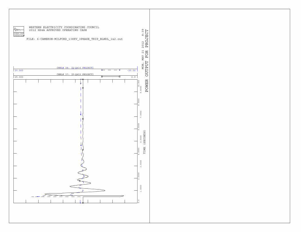
CHNL# 37: [P-Q415 PROJECT]25.000 0.0
CHNL# 38: [Q-Q415 PROJECT]20.000 -20.00
WESTERN ELECTRICITY COORDINATING COUNCIL 2012 HS4A APPROVED OPERATING CASE
MON, MAY 21 2012 8:39
TIME (SECONDS)
SIEMENS POWERTECHNOLOGIESINTERNATIONAL
0.0
1.0000
2.0000
3.0000
4.0000
5.0000
6.0000
7.0000
8.0000
9.000010.000
FILE: 6-CAMERON-MILFORD_138KV_3PHASE_TRIP_BLNDL_1&2.out
POWER OUTPUT FOR PROJECT

Dynamic Simulation Plots Milford - Cameron 138 kV line Outage, Blundell units #1 tripped 30 cycles Three Phase fault – Milford 138kV 36 cycles Clear fault at Milford, open line Cameron – Milford 138 kV line 46 cycles Trip Blundell units #1 10 seconds Terminate simulation
B-7
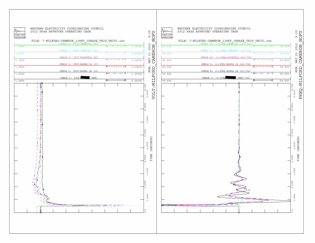
CHNL# 1: [VLT- _GEN]1.2000 0.20000
CHNL# 2: [VLT-BLNDL G2 12]1.2000 0.20000
CHNL# 3: [VLT-BLNDL G1 12]1.2000 0.20000
CHNL# 4: [VLT-BLUNDELL 46]1.2000 0.20000
CHNL# 5: [VLT-SOMLFRD 46]1.2000 0.20000
CHNL# 6: [VLT-CAMERON 138]1.2000 0.20000
WESTERN ELECTRICITY COORDINATING COUNCIL 2012 HS4A APPROVED OPERATING CASE
MON, MAY 21 2012 8:39
TIME (SECONDS)
SIEMENS POWERTECHNOLOGIESINTERNATIONAL
0.0
1.0000
2.0000
3.0000
4.0000
5.0000
6.0000
7.0000
8.0000
9.000010.000
FILE: 7-MILFORD-CAMERON_138KV_3PHASE_TRIP_UNIT1.out
VOLT:MILFORD_CAMERON_NOFU
CHNL# 7: (1+[FRQ _GEN])*6060.600 59.600
CHNL# 8: (1+[FRQ-BLNDL G2 12])*6060.600 59.600
CHNL# 9: (1+[FRQ-BLNDL G1 12])*6060.600 59.600
CHNL# 10: (1+[FRQ-BLUNDELL 46])*6060.600 59.600
CHNL# 11: (1+[FRQ-SOMLFRD 46])*6060.600 59.600
CHNL# 12: (1+[FRQ-CAMERON 138])*6060.600 59.600
WESTERN ELECTRICITY COORDINATING COUNCIL 2012 HS4A APPROVED OPERATING CASE
MON, MAY 21 2012 8:39
TIME (SECONDS)
SIEMENS POWERTECHNOLOGIESINTERNATIONAL
0.0
1.0000
2.0000
3.0000
4.0000
5.0000
6.0000
7.0000
8.0000
9.000010.000
FILE: 7-MILFORD-CAMERON_138KV_3PHASE_TRIP_UNIT1.out
FREQ:MILFORD_CAMERON_NOFU
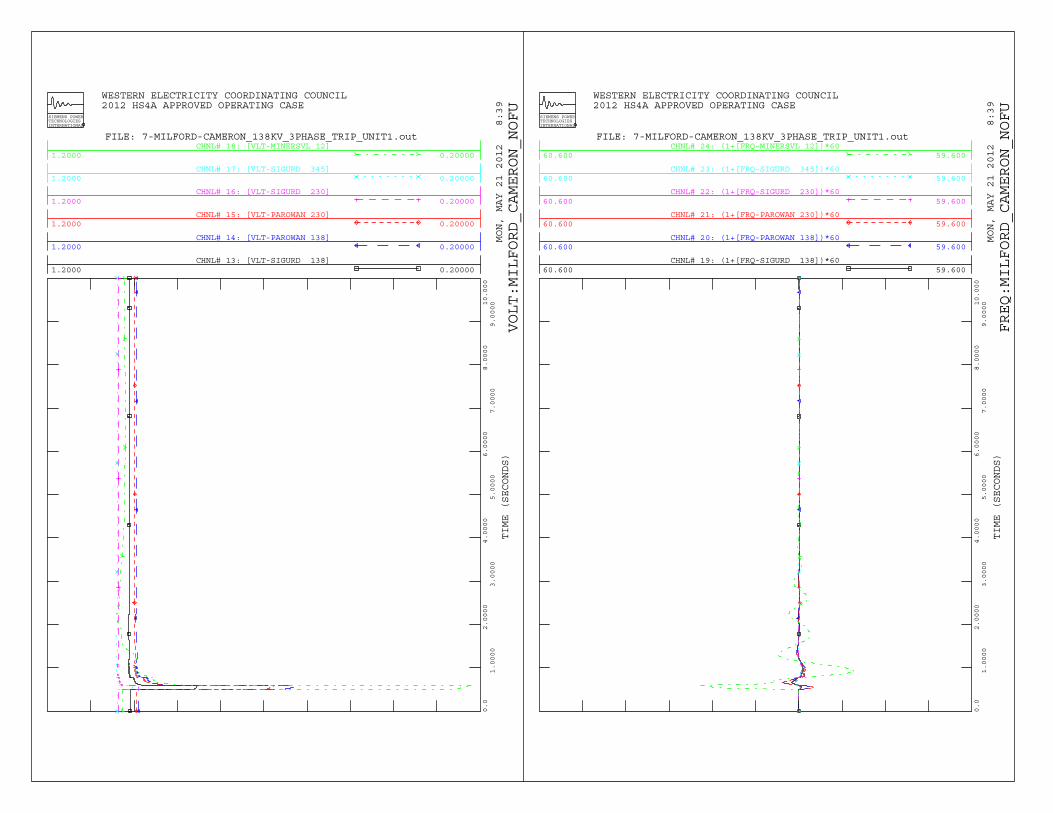
CHNL# 13: [VLT-SIGURD 138]1.2000 0.20000
CHNL# 14: [VLT-PAROWAN 138]1.2000 0.20000
CHNL# 15: [VLT-PAROWAN 230]1.2000 0.20000
CHNL# 16: [VLT-SIGURD 230]1.2000 0.20000
CHNL# 17: [VLT-SIGURD 345]1.2000 0.20000
CHNL# 18: [VLT-MINERSVL 12]1.2000 0.20000
WESTERN ELECTRICITY COORDINATING COUNCIL 2012 HS4A APPROVED OPERATING CASE
MON, MAY 21 2012 8:39
TIME (SECONDS)
SIEMENS POWERTECHNOLOGIESINTERNATIONAL
0.0
1.0000
2.0000
3.0000
4.0000
5.0000
6.0000
7.0000
8.0000
9.000010.000
FILE: 7-MILFORD-CAMERON_138KV_3PHASE_TRIP_UNIT1.out
VOLT:MILFORD_CAMERON_NOFU
CHNL# 19: (1+[FRQ-SIGURD 138])*6060.600 59.600
CHNL# 20: (1+[FRQ-PAROWAN 138])*6060.600 59.600
CHNL# 21: (1+[FRQ-PAROWAN 230])*6060.600 59.600
CHNL# 22: (1+[FRQ-SIGURD 230])*6060.600 59.600
CHNL# 23: (1+[FRQ-SIGURD 345])*6060.600 59.600
CHNL# 24: (1+[FRQ-MINERSVL 12])*6060.600 59.600
WESTERN ELECTRICITY COORDINATING COUNCIL 2012 HS4A APPROVED OPERATING CASE
MON, MAY 21 2012 8:39
TIME (SECONDS)
SIEMENS POWERTECHNOLOGIESINTERNATIONAL
0.0
1.0000
2.0000
3.0000
4.0000
5.0000
6.0000
7.0000
8.0000
9.000010.000
FILE: 7-MILFORD-CAMERON_138KV_3PHASE_TRIP_UNIT1.out
FREQ:MILFORD_CAMERON_NOFU
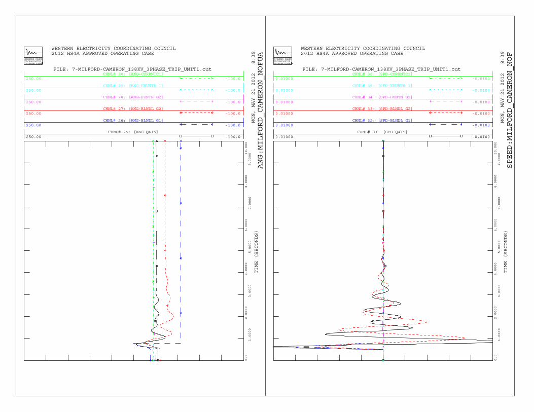
CHNL# 25: [ANG-Q415]250.00 -100.0
CHNL# 26: [ANG-BLNDL G1]250.00 -100.0
CHNL# 27: [ANG-BLNDL G2]250.00 -100.0
CHNL# 28: [ANG-HUNTN G2]250.00 -100.0
CHNL# 29: [ANG-EHUNTR 1]250.00 -100.0
CHNL# 30: [ANG-CURRNTC1]250.00 -100.0
WESTERN ELECTRICITY COORDINATING COUNCIL 2012 HS4A APPROVED OPERATING CASE
MON, MAY 21 2012 8:39
TIME (SECONDS)
SIEMENS POWERTECHNOLOGIESINTERNATIONAL
0.0
1.0000
2.0000
3.0000
4.0000
5.0000
6.0000
7.0000
8.0000
9.000010.000
FILE: 7-MILFORD-CAMERON_138KV_3PHASE_TRIP_UNIT1.out
ANG:MILFORD_CAMERON_NOFUA
CHNL# 31: [SPD-Q415]0.01000 -0.0100
CHNL# 32: [SPD-BLNDL G1]0.01000 -0.0100
CHNL# 33: [SPD-BLNDL G2]0.01000 -0.0100
CHNL# 34: [SPD-HUNTN G2]0.01000 -0.0100
CHNL# 35: [SPD-EHUNTR 1]0.01000 -0.0100
CHNL# 36: [SPD-CURRNTC1]0.01000 -0.0100
WESTERN ELECTRICITY COORDINATING COUNCIL 2012 HS4A APPROVED OPERATING CASE
MON, MAY 21 2012 8:39
TIME (SECONDS)
SIEMENS POWERTECHNOLOGIESINTERNATIONAL
0.0
1.0000
2.0000
3.0000
4.0000
5.0000
6.0000
7.0000
8.0000
9.000010.000
FILE: 7-MILFORD-CAMERON_138KV_3PHASE_TRIP_UNIT1.out
SPEED:MILFORD_CAMERON_NOF
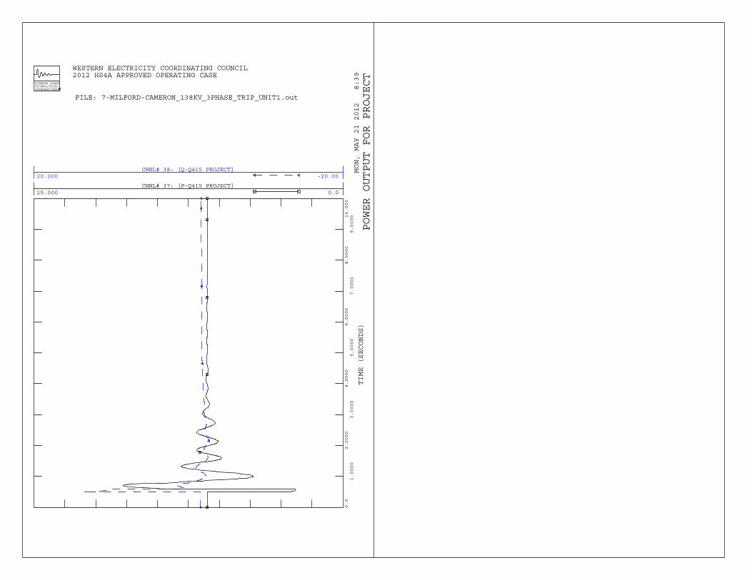
CHNL# 37: [P-Q415 PROJECT]25.000 0.0
CHNL# 38: [Q-Q415 PROJECT]20.000 -20.00
WESTERN ELECTRICITY COORDINATING COUNCIL 2012 HS4A APPROVED OPERATING CASE
MON, MAY 21 2012 8:39
TIME (SECONDS)
SIEMENS POWERTECHNOLOGIESINTERNATIONAL
0.0
1.0000
2.0000
3.0000
4.0000
5.0000
6.0000
7.0000
8.0000
9.000010.000
FILE: 7-MILFORD-CAMERON_138KV_3PHASE_TRIP_UNIT1.out
POWER OUTPUT FOR PROJECT

Dynamic Simulation Plots Milford - Cameron 138 kV line Outage 30 cycles No fault open Cameron – Milford 138 kV line 10 seconds Terminate simulation
B-8
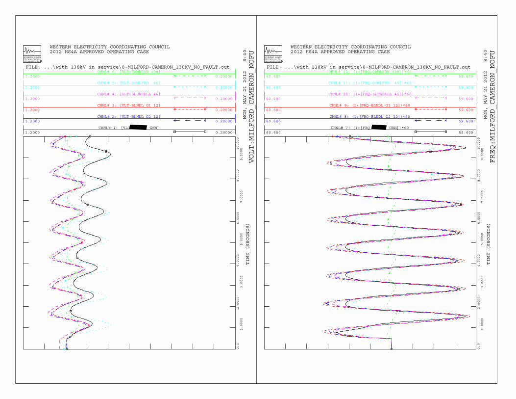
CHNL# 1: [VLT _GEN]1.2000 0.20000
CHNL# 2: [VLT-BLNDL G2 12]1.2000 0.20000
CHNL# 3: [VLT-BLNDL G1 12]1.2000 0.20000
CHNL# 4: [VLT-BLUNDELL 46]1.2000 0.20000
CHNL# 5: [VLT-SOMLFRD 46]1.2000 0.20000
CHNL# 6: [VLT-CAMERON 138]1.2000 0.20000
WESTERN ELECTRICITY COORDINATING COUNCIL 2012 HS4A APPROVED OPERATING CASE
MON, MAY 21 2012 8:40
TIME (SECONDS)
SIEMENS POWERTECHNOLOGIESINTERNATIONAL
0.0
1.0000
2.0000
3.0000
4.0000
5.0000
6.0000
7.0000
8.0000
9.000010.000
FILE: ...\with 138kV in service\8-MILFORD-CAMERON_138KV_NO_FAULT.out
VOLT:MILFORD_CAMERON_NOFU
CHNL# 7: (1+[FRQ _GEN])*6060.600 59.600
CHNL# 8: (1+[FRQ-BLNDL G2 12])*6060.600 59.600
CHNL# 9: (1+[FRQ-BLNDL G1 12])*6060.600 59.600
CHNL# 10: (1+[FRQ-BLUNDELL 46])*6060.600 59.600
CHNL# 11: (1+[FRQ-SOMLFRD 46])*6060.600 59.600
CHNL# 12: (1+[FRQ-CAMERON 138])*6060.600 59.600
WESTERN ELECTRICITY COORDINATING COUNCIL 2012 HS4A APPROVED OPERATING CASE
MON, MAY 21 2012 8:40
TIME (SECONDS)
SIEMENS POWERTECHNOLOGIESINTERNATIONAL
0.0
1.0000
2.0000
3.0000
4.0000
5.0000
6.0000
7.0000
8.0000
9.000010.000
FILE: ...\with 138kV in service\8-MILFORD-CAMERON_138KV_NO_FAULT.out
FREQ:MILFORD_CAMERON_NOFU
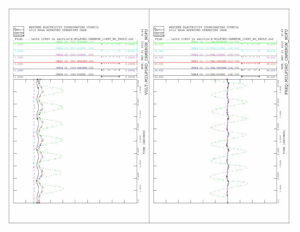
CHNL# 13: [VLT-SIGURD 138]1.2000 0.20000
CHNL# 14: [VLT-PAROWAN 138]1.2000 0.20000
CHNL# 15: [VLT-PAROWAN 230]1.2000 0.20000
CHNL# 16: [VLT-SIGURD 230]1.2000 0.20000
CHNL# 17: [VLT-SIGURD 345]1.2000 0.20000
CHNL# 18: [VLT-MINERSVL 12]1.2000 0.20000
WESTERN ELECTRICITY COORDINATING COUNCIL 2012 HS4A APPROVED OPERATING CASE
MON, MAY 21 2012 8:40
TIME (SECONDS)
SIEMENS POWERTECHNOLOGIESINTERNATIONAL
0.0
1.0000
2.0000
3.0000
4.0000
5.0000
6.0000
7.0000
8.0000
9.000010.000
FILE: ...\with 138kV in service\8-MILFORD-CAMERON_138KV_NO_FAULT.out
VOLT:MILFORD_CAMERON_NOFU
CHNL# 19: (1+[FRQ-SIGURD 138])*6060.600 59.600
CHNL# 20: (1+[FRQ-PAROWAN 138])*6060.600 59.600
CHNL# 21: (1+[FRQ-PAROWAN 230])*6060.600 59.600
CHNL# 22: (1+[FRQ-SIGURD 230])*6060.600 59.600
CHNL# 23: (1+[FRQ-SIGURD 345])*6060.600 59.600
CHNL# 24: (1+[FRQ-MINERSVL 12])*6060.600 59.600
WESTERN ELECTRICITY COORDINATING COUNCIL 2012 HS4A APPROVED OPERATING CASE
MON, MAY 21 2012 8:40
TIME (SECONDS)
SIEMENS POWERTECHNOLOGIESINTERNATIONAL
0.0
1.0000
2.0000
3.0000
4.0000
5.0000
6.0000
7.0000
8.0000
9.000010.000
FILE: ...\with 138kV in service\8-MILFORD-CAMERON_138KV_NO_FAULT.out
FREQ:MILFORD_CAMERON_NOFU
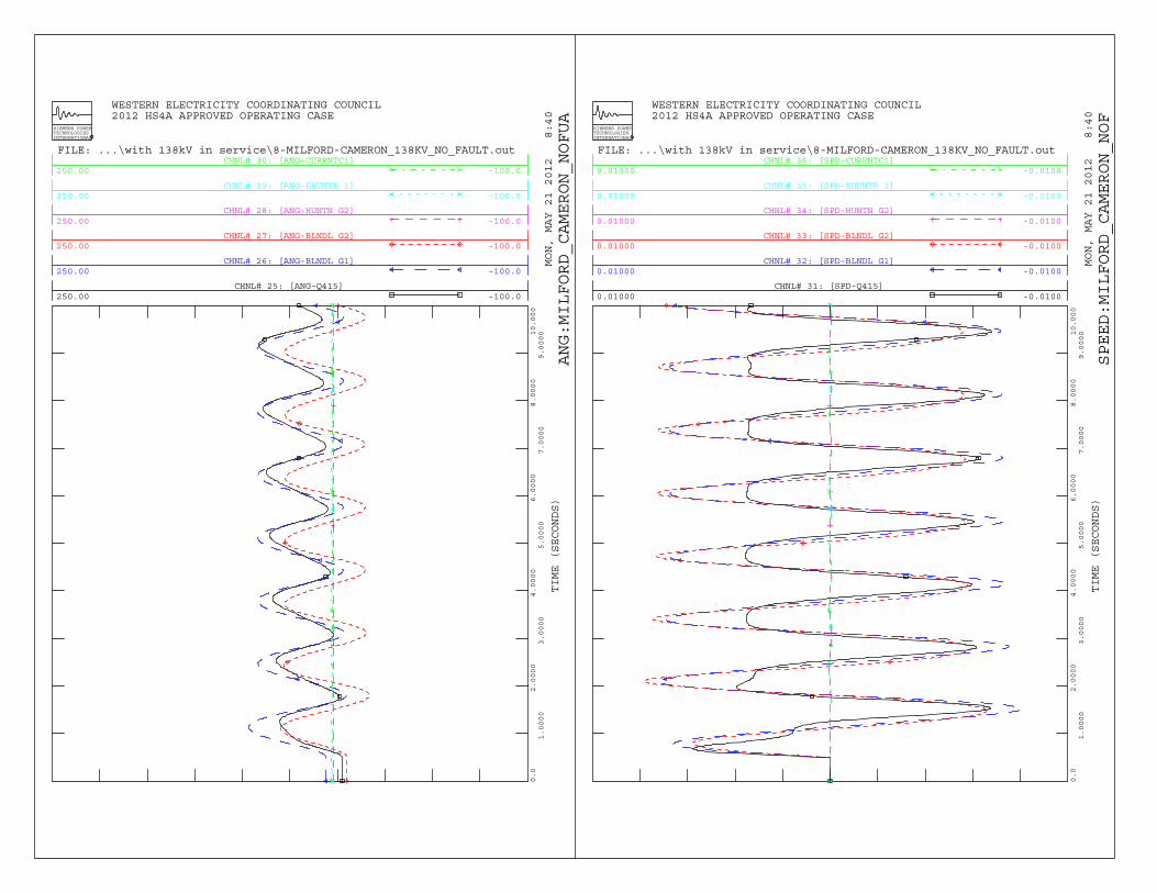
CHNL# 25: [ANG-Q415]250.00 -100.0
CHNL# 26: [ANG-BLNDL G1]250.00 -100.0
CHNL# 27: [ANG-BLNDL G2]250.00 -100.0
CHNL# 28: [ANG-HUNTN G2]250.00 -100.0
CHNL# 29: [ANG-EHUNTR 1]250.00 -100.0
CHNL# 30: [ANG-CURRNTC1]250.00 -100.0
WESTERN ELECTRICITY COORDINATING COUNCIL 2012 HS4A APPROVED OPERATING CASE
MON, MAY 21 2012 8:40
TIME (SECONDS)
SIEMENS POWERTECHNOLOGIESINTERNATIONAL
0.0
1.0000
2.0000
3.0000
4.0000
5.0000
6.0000
7.0000
8.0000
9.000010.000
FILE: ...\with 138kV in service\8-MILFORD-CAMERON_138KV_NO_FAULT.out
ANG:MILFORD_CAMERON_NOFUA
CHNL# 31: [SPD-Q415]0.01000 -0.0100
CHNL# 32: [SPD-BLNDL G1]0.01000 -0.0100
CHNL# 33: [SPD-BLNDL G2]0.01000 -0.0100
CHNL# 34: [SPD-HUNTN G2]0.01000 -0.0100
CHNL# 35: [SPD-EHUNTR 1]0.01000 -0.0100
CHNL# 36: [SPD-CURRNTC1]0.01000 -0.0100
WESTERN ELECTRICITY COORDINATING COUNCIL 2012 HS4A APPROVED OPERATING CASE
MON, MAY 21 2012 8:40
TIME (SECONDS)
SIEMENS POWERTECHNOLOGIESINTERNATIONAL
0.0
1.0000
2.0000
3.0000
4.0000
5.0000
6.0000
7.0000
8.0000
9.000010.000
FILE: ...\with 138kV in service\8-MILFORD-CAMERON_138KV_NO_FAULT.out
SPEED:MILFORD_CAMERON_NOF
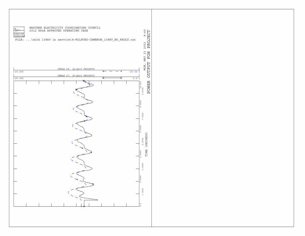
CHNL# 37: [P-Q415 PROJECT]25.000 0.0
CHNL# 38: [Q-Q415 PROJECT]20.000 -20.00
WESTERN ELECTRICITY COORDINATING COUNCIL 2012 HS4A APPROVED OPERATING CASE
MON, MAY 21 2012 8:40
TIME (SECONDS)
SIEMENS POWERTECHNOLOGIESINTERNATIONAL
0.0
1.0000
2.0000
3.0000
4.0000
5.0000
6.0000
7.0000
8.0000
9.000010.000
FILE: ...\with 138kV in service\8-MILFORD-CAMERON_138KV_NO_FAULT.out
POWER OUTPUT FOR PROJECT

B-9
Dynamic Simulation Plots Milford - Cameron 138 kV line Outage, Q415 tripped 30 cycles Three Phase fault – Milford 138kV 36 cycles Clear fault at Milford, open line Cameron – Milford 138 kV line 46 cycles Trip Q415 project generator 10 seconds Terminate simulation
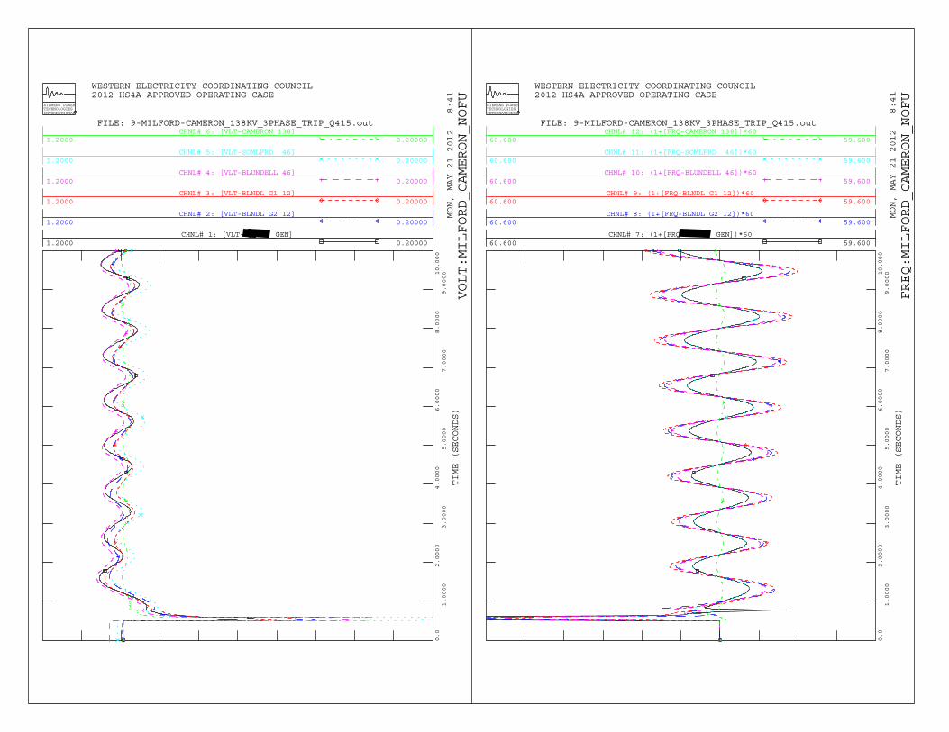
CHNL# 1: [VLT- _GEN]1.2000 0.20000
CHNL# 2: [VLT-BLNDL G2 12]1.2000 0.20000
CHNL# 3: [VLT-BLNDL G1 12]1.2000 0.20000
CHNL# 4: [VLT-BLUNDELL 46]1.2000 0.20000
CHNL# 5: [VLT-SOMLFRD 46]1.2000 0.20000
CHNL# 6: [VLT-CAMERON 138]1.2000 0.20000
WESTERN ELECTRICITY COORDINATING COUNCIL 2012 HS4A APPROVED OPERATING CASE
MON, MAY 21 2012 8:41
TIME (SECONDS)
SIEMENS POWERTECHNOLOGIESINTERNATIONAL
0.0
1.0000
2.0000
3.0000
4.0000
5.0000
6.0000
7.0000
8.0000
9.000010.000
FILE: 9-MILFORD-CAMERON_138KV_3PHASE_TRIP_Q415.out
VOLT:MILFORD_CAMERON_NOFU
CHNL# 7: (1+[FRQ _GEN])*6060.600 59.600
CHNL# 8: (1+[FRQ-BLNDL G2 12])*6060.600 59.600
CHNL# 9: (1+[FRQ-BLNDL G1 12])*6060.600 59.600
CHNL# 10: (1+[FRQ-BLUNDELL 46])*6060.600 59.600
CHNL# 11: (1+[FRQ-SOMLFRD 46])*6060.600 59.600
CHNL# 12: (1+[FRQ-CAMERON 138])*6060.600 59.600
WESTERN ELECTRICITY COORDINATING COUNCIL 2012 HS4A APPROVED OPERATING CASE
MON, MAY 21 2012 8:41
TIME (SECONDS)
SIEMENS POWERTECHNOLOGIESINTERNATIONAL
0.0
1.0000
2.0000
3.0000
4.0000
5.0000
6.0000
7.0000
8.0000
9.000010.000
FILE: 9-MILFORD-CAMERON_138KV_3PHASE_TRIP_Q415.out
FREQ:MILFORD_CAMERON_NOFU
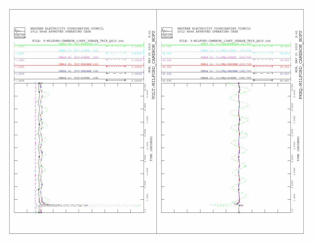
CHNL# 13: [VLT-SIGURD 138]1.2000 0.20000
CHNL# 14: [VLT-PAROWAN 138]1.2000 0.20000
CHNL# 15: [VLT-PAROWAN 230]1.2000 0.20000
CHNL# 16: [VLT-SIGURD 230]1.2000 0.20000
CHNL# 17: [VLT-SIGURD 345]1.2000 0.20000
CHNL# 18: [VLT-MINERSVL 12]1.2000 0.20000
WESTERN ELECTRICITY COORDINATING COUNCIL 2012 HS4A APPROVED OPERATING CASE
MON, MAY 21 2012 8:41
TIME (SECONDS)
SIEMENS POWERTECHNOLOGIESINTERNATIONAL
0.0
1.0000
2.0000
3.0000
4.0000
5.0000
6.0000
7.0000
8.0000
9.000010.000
FILE: 9-MILFORD-CAMERON_138KV_3PHASE_TRIP_Q415.out
VOLT:MILFORD_CAMERON_NOFU
CHNL# 19: (1+[FRQ-SIGURD 138])*6060.600 59.600
CHNL# 20: (1+[FRQ-PAROWAN 138])*6060.600 59.600
CHNL# 21: (1+[FRQ-PAROWAN 230])*6060.600 59.600
CHNL# 22: (1+[FRQ-SIGURD 230])*6060.600 59.600
CHNL# 23: (1+[FRQ-SIGURD 345])*6060.600 59.600
CHNL# 24: (1+[FRQ-MINERSVL 12])*6060.600 59.600
WESTERN ELECTRICITY COORDINATING COUNCIL 2012 HS4A APPROVED OPERATING CASE
MON, MAY 21 2012 8:41
TIME (SECONDS)
SIEMENS POWERTECHNOLOGIESINTERNATIONAL
0.0
1.0000
2.0000
3.0000
4.0000
5.0000
6.0000
7.0000
8.0000
9.000010.000
FILE: 9-MILFORD-CAMERON_138KV_3PHASE_TRIP_Q415.out
FREQ:MILFORD_CAMERON_NOFU

CHNL# 25: [ANG-Q415]250.00 -100.0
CHNL# 26: [ANG-BLNDL G1]250.00 -100.0
CHNL# 27: [ANG-BLNDL G2]250.00 -100.0
CHNL# 28: [ANG-HUNTN G2]250.00 -100.0
CHNL# 29: [ANG-EHUNTR 1]250.00 -100.0
CHNL# 30: [ANG-CURRNTC1]250.00 -100.0
WESTERN ELECTRICITY COORDINATING COUNCIL 2012 HS4A APPROVED OPERATING CASE
MON, MAY 21 2012 8:41
TIME (SECONDS)
SIEMENS POWERTECHNOLOGIESINTERNATIONAL
0.0
1.0000
2.0000
3.0000
4.0000
5.0000
6.0000
7.0000
8.0000
9.000010.000
FILE: 9-MILFORD-CAMERON_138KV_3PHASE_TRIP_Q415.out
ANG:MILFORD_CAMERON_NOFUA
CHNL# 31: [SPD-Q415]0.01000 -0.0100
CHNL# 32: [SPD-BLNDL G1]0.01000 -0.0100
CHNL# 33: [SPD-BLNDL G2]0.01000 -0.0100
CHNL# 34: [SPD-HUNTN G2]0.01000 -0.0100
CHNL# 35: [SPD-EHUNTR 1]0.01000 -0.0100
CHNL# 36: [SPD-CURRNTC1]0.01000 -0.0100
WESTERN ELECTRICITY COORDINATING COUNCIL 2012 HS4A APPROVED OPERATING CASE
MON, MAY 21 2012 8:41
TIME (SECONDS)
SIEMENS POWERTECHNOLOGIESINTERNATIONAL
0.0
1.0000
2.0000
3.0000
4.0000
5.0000
6.0000
7.0000
8.0000
9.000010.000
FILE: 9-MILFORD-CAMERON_138KV_3PHASE_TRIP_Q415.out
SPEED:MILFORD_CAMERON_NOF
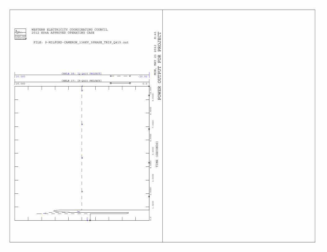
CHNL# 37: [P-Q415 PROJECT]25.000 0.0
CHNL# 38: [Q-Q415 PROJECT]20.000 -20.00
WESTERN ELECTRICITY COORDINATING COUNCIL 2012 HS4A APPROVED OPERATING CASE
MON, MAY 21 2012 8:41
TIME (SECONDS)
SIEMENS POWERTECHNOLOGIESINTERNATIONAL
0.0
1.0000
2.0000
3.0000
4.0000
5.0000
6.0000
7.0000
8.0000
9.000010.000
FILE: 9-MILFORD-CAMERON_138KV_3PHASE_TRIP_Q415.out
POWER OUTPUT FOR PROJECT