SMALL DAMS PETITS BARRAGES
149
1 SMALL DAMS Design, Surveillance and Rehabilitation PETITS BARRAGES Conception, Surveillance et Réhabilitation 2011 BULLETIN N o ... (
Transcript of SMALL DAMS PETITS BARRAGES
1
SMALL DAMS Design, Surveillance and Rehabilitation
PETITS BARRAGES Conception, Surveillance et Réhabilitation
2011
BULLETIN No ... (

2
AD HOC COMMITTEE ON SMALL DAMS
(2005-2010) Chairman/Président Brazil J.F.A. SILVEIRA
Members/Membres
Bulgaria C. B. ABADJIEV Canada G. VERZENI
P. MITCHELMORE (1) China J. SHENG
Czech Republic J. POLACEK France P. ROYET
India G. N. MATHUR(2) V.K.KANJLIA
Iran J. ATTARI (3) A. SOROUSH (4)
Japan Y. MATSUURA
Lebanon A. MEOUCHY (5) Morroco A. LABRAIMI (6)
Nigeria OLA, SAMUEL Pakistan I. B. SHAIKH (7) Russia S. A. SHMANENKOV South Africa D. BADENHORST Spain Sweden
F.J.S.CABEZAS (8) Y. HELMFRID (9)
The United States D. MILLER
United Kingdom A. HUGHES Australia (corresp. member) P. CUMMINS (1) Member since May 2009 (2) Member until December 2008 (3) Member until June 2007 (4) Member since Jan 2008 (5) Member since June 2008 (6) Member since June 2006 (7) Member since June 2006 (8) Member since June 2008 (9) Member since June 2010

3
FOREWORD
The ICOLD – International Committee on Large Dams decided to prepare a bulletin on small dams in consideration to the great number of this type of dams, that represents generally more than 90% of the total number of dams.
There are clear evidences of the construction of the first small dams about 5000 years ago in Jordan, about 4600 years ago in Egypt and Baluchistan, and from 3250 to 3500 in Turkey, Yemen and Greece. These data and other with a “Historical Review on Ancient Dams” are presented at the ICOLD Bulletin No 143, to be published in 2011 by ICOLD.
This bulletin was prepared as a guide for small dam owners, engineering, Government agencies, developers and contractors who are in charge with the design, construction, operation, maintenance and safety of small dams. This bulletin was developed mainly to the embankment dams which represent the very large majority of small dam. It is however important to point out that laws and regulations vary with different countries, and may even be stricter than the guidelines in this bulletin.
In this bulletin “Small Dams” are defined as having the following characteristics:
o 2,5 m < H < 15 m and VH .2< 200
o H is height in meters above river bed level to maximum crest level o V is storage volume in million m3 at maximum operating level = full supply level.
Design criteria and typical features for small dams are generally different from those for high dams, because the construction methods focus upon economy. So the risk may increase and corresponding accidents may cause significant victims. The basic principle of design is to produce a satisfactory functional structure at a minimum total cost. At the “Features of the Design of Small Embankment Dams” are presented the important contributions from China, United States, France, South Africa, Australia, Czech Republic and Japan, related to the recommended embankment slopes for small dams based on the experience with the construction of a large number of those small structures. “Guidelines on Surveillance of Small Dams” presents the main recommendations in order to assure that the dams will behave appropriately and with a minimum cost. The construction of a dam can involve a significant investment and dam owners need to ensure that their money is well spent and that their dam becomes an asset.
Ageing of embankment dams, updating of design standards and criteria and the deterioration of conditions affecting the safety of small dams are analyzed in detail at the “Rehabilitation Practices for Small Dams”, emphasizing the main remedial measures related to embankment dams.
At the “Emergency Action Plan (EAP)” are emphasized the main points concerned the application of such plan to minimize the consequences of a dam failure or malfunction, regarding the population living downstream, presenting some recommendation about how to develop an EAP, evaluating the possible dam risks and the management of the dam safety.
At the “Legislation & Decommissioning” chapter are pointed out the dam safety and security of people, property and environment downstream of dams and the important responsibility of the Government, who must legislate and enforce the rules through administrative agencies, departments and offices.

4
It is important to be in charge with the performance of our large dams, but also with the performance of the small one, as a consequence of the large number of these dams. We had the opportunity to learn that in most countries more than 90 % are small dams, which failure consequences can be catastrophic to the downstream residents, infrastructure and the environment.
JOÃO FRANCISCO A. SILVEIRA
Chairman of the Ad Hoc Committee on Small Dams

5
ACKNOWLEDGEMENT
The Ad Hoc Committee on Small Dams and the ICOLD Executive gratefully acknowledge, initially, the suggestion of Mr. C.V.J. Varma from India, to create this committee, during the 72nd Annual ICOLD Meeting, in Seoul, 2004, when he was the ICOLD President, and also to Mr. C.B. Viotti from Brasil, the next ICOLD President, for its creation at the 73rd Annual ICOLD Meeting, in Tehran, 2005. In the elaboration of the “Historical Review on Ancient Dams”, that is just the Volume I of our ICOLD Committee, we received the special collaboration from the following members: Mr. Mathur, from India, Mr. Matsuura, from Japan, Mrs. Miller, from The United States, Mr. Polacek, from Czech Republic, Mr. Royet, from France, Mr. Sheng, from China, Mr. Attari, from Iran, and Mr. Yong-Nam, from Korea. In the elaboration of the “Small Dams – Design, Surveillance and Rehabilitation”, that is the Volume II of our ICOLD Committee, we received collaborations from all our members, but some very important one from Mr. Royet, from France, Mr. Badenhorst, from South Africa, Mr. Abadjiev, from Bulgaria, Mr. Matsuura, from Japan, Mr. Polacek, from Czech Republic and Mr Sánchez, from Spain.
6
TABLE OF CONTENTS
-
FOREWORD
03
-
ACKNOWLEDGEMENT
05
1
SMALL DAMS DEFINITON AND CLASSIFICATION
13
2
TYPES OF SMALL DAMS
18
3
SAFETY OF SMALL DAMS
31
4 LEGISLATION & DECOMMISSIONING 40
5
FEATURES OF THE DESIGN OF SMALL EMBANKMENT DAMS
49
6
GUIDELINES ON SURVEILLANCE OF SMALL DAMS
93
7
REHABILITATION PRACTICES FOR SMALL DAMS
114
8
EMERGENCY ACTION PLAN FOR SMALL DAMS
140
TOTAL
149
7
TABLE OF CONTENTS
FOREWORD
ACKNOWLEDGEMENT
SUMMARY
1. SMALL DAMS DEFINITION AND CLASSIFICATION
1.1 Classification
1.2 Definition of small dams
1.3 References
2. TYPES OF SMALL DAMS
2.1 Introduction
2.2 Homogeneous earthfill dams
2.3 Zoned earthfill dams
2.3.1 Central clay core dams
2.3.2 Sloping core dams
2.3.3 Zhaogushe dams
2.4 Stone masonry dams
2.5 Concrete gravity dams
2.6 Concrete buttress dams
2.7 Gabion dams
2.8 Inflatable dam type
2.9 References
3. SAFETY OF SMALL DAMS
3.1 Introduction
3.2 Conditions affecting the safety
3.3 Causes of dam failures
3.3.1 General

8
3.3.2 Overtopping caused by flood
3.3.3 Internal erosion
3.3.4 Slope instability
3.4 References
4. LEGISLATION & DECOMMISSIONING
4.1 Introduction
4.2 The regulation
4.3 The supervising authority
4.4 The owner
4.5 Decommissioning
4.6 Conclusion
4.7 References
5. FEATURES OF THE DESIGN OF SMALL EMBANKMENT DAMS
5.1 Introduction
5.2 Design floods
5.3 Homogenous and zoned embankments design
5.3.1 Homogenous type
5.3.2 Zoned embankment type
5.4 Freeboard
5.4.1 Definitions of freeboard
5.4.2 Freeboard design considerations
5.4.3 Freeboard design for wave run-up and wind setup
5.4.4 First approximations for freeboard requirements
5.4.5 Camber
5.5 Soil compaction
5.5.1 Compaction standards
5.5.2 Water content variation and effect on geomechanical properties
5.5.3 Layer thicknesses
5.5.4 Quality control during compaction
9
5.5.5 Compaction in confined areas
5.5.6 Testing of the pipe
5.5.7 Compaction of filters
5.6 Dam foundation treatment
5.6.1 Foundation watertightness
5.6.2 Foundation drainage
5.7 Drainage system for earthfill dams
5.7.1 Seepage control measures
5.7.1.1 Measures for pervious ground
5.7.1.2 Blanket grouting method
5.7.1.3 Artificial blanket
5.7.1.4 Practical considerations
5.7.1.5 Filter material criteria
5.7.1.6 Piping prevention criteria
5.7.1.7 Criteria regarding permeability
5.7.1.8 Uniform criteria
5.7.1.9 Criteria for the inherent stability of a filter
5.7.1.10 Cohesion clay criteria
5.7.1.11 Criteria regarding dispersive clay
5.7.1.12 Organic material criteria
5.7.1.13 Criteria and practice regarding synthetic materials
5.8 Slope stability
5.8.1 Introduction
5.8.2 Critical cases for analysis
5.8.3 Limiting equilibrium methods
5.8.4 Minimum safety factors against slipe circle failures
5.9 Surface drainage
5.9.1 Principles
5.9.2 Possible mechanical solution of the surface dewatering
10
5.10 Slope protection
5.10.1 Upstream slope protection
5.10.2 Selecting the type of upstream protection
5.10.3 Dowstream slope protection with grass
5.10.4 Dowstream slope protection with gravel
5.10.5 Protection from seepage piping
5.11 Crest design
5.11.1 Width
5.11.2 Drainage
5.11.3 Allowance for settlement
5.11.4 Surfacing
5.11.5 Traffic safety requirements
5.12 Construction techniques for the foundation and the fill
5.13 References
6. GUIDELINES ON SURVEILLANCE OF SMALL DAMS
6.1 Introduction
6.2 Safety surveillance
6.3 Surveillance practices
6.3.1 Inspection procedures
6.3.2 Dam inspection and performance evaluation
6.3.3 Inspections after earthquakes
6.4 Monitoring system
6.4.1 Monitoring instruments for small dams
6.4.2 Guidelines on dam monitoring
6.4.3 Data analysis and reporting
6.5 References
7. REHABILITATION PRACTICES FOR SMALL DAMS
7.1 Introduction
7.2 Techniques for improving spillway safety

11
7.2.1 Introduction
7.2.2 Spillway capacity
7.2.3 Backward erosion control
7.2.4 Spillway chute or spillway return channel alignment
7.2.5 Deformation of spillway structures provided over embankments
7.2.6 Erosion of the abutment wall between the embankment and the spillway
7.2.7 Gabions used as sill in by-pass channels
7.3 Techniques for improving embankment safety
7.3.1 Techniques to overcome flood handling problem
7.3.1.1 Parapet wall
7.3.1.2 Raise embankment crest
7.3.1.3 Protection of embankment from erosion during overtopping
7.3.2 Slope stability
7.3.3 Piping control measures
7.3.4 Seepage control measures
7.3.4.1 Seepage barriers and cutoff systems
7.3.4.2 Seepage interception and exit control with filters and drains
7.3.5 Slope protection measures
7.3.5.1 Vegetal protection
7.3.5.2 Rip-rap or gravel protection of the downstream face of the embankment
7.3.6 Techniques for the rehabilitation of bottom outlets on embankment dams
7.3.6.1 Renovation of conduits
7.3.6.2 Filter around conduits
7.3.6.3 Pipe abandonment
7.3.7 Techniques for rehabilitation of hydromechanical components
7.3.8 Restoring reservoir capacity in case of siltation
7.4 References
8. GUIDELINES ON EMERGENCY ACTION PLAN (EAP)
8.1 Introduction

12
8.2 How to develop an emergency action plan
8.3 Evaluation of possible risks
8.3.1 Overtopping during extremes floods
8.3.2 Piping and internal erosion
8.3.3 Earthquake
8.3.4 Failure of upstream dams
8.3.5 Failure of slopes in the reservoir
8.3.6 Sabotage
8.4 Small dam risk management
8.5 Dam site access during severe storms
8.6 Dam break and inundation map
8.7 Permanent file for emergency purposes
8.8 Emergency exercising and updating
8.9 References
13
1. SMALL DAMS DEFINITION AND CLASSIFICATION
The term “small dams” has various meanings and perceptions in the world. For some a 20m high dam will be the largest of the small dams category, while others see it as the smallest large dam. Dams are being defined as having a safety risk when the dam height is higher than 2m in America and 5m in South Africa, and having a storage capacity of a 30 000 m3 and 50 000 m3 respectively.
Furthermore, the concept of consequential damages and loss of life for the case of a
dam failure is widely used for classification of all dams into hazard classes, normally as low, medium and high. The consequential damages are determined for the inundated area caused by a dam break flooding event. Dam storage volume, depth of water at the dam wall and time of the development of the breach are the most important parameters for the determination of the dam break flood.
Large dams are being defined by ICOLD as any dam with:
maximum height (H), measured from deepest foundation level to highest structure crest level, more than 15m, or
10m < H < 15m, and the following conditions: • dam length more than 500 m, • reservoir storage capacity more than 3 million m3, • flood discharge more than 2 000 m3/s, and • unusual characteristics in dam type or foundation. • suggestions and references
1.1 CLASSIFICATION
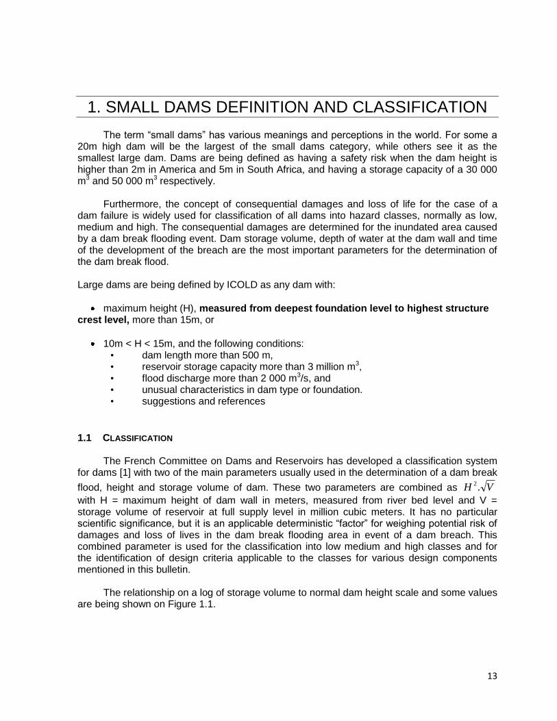
The French Committee on Dams and Reservoirs has developed a classification system
for dams [1] with two of the main parameters usually used in the determination of a dam break
flood, height and storage volume of dam. These two parameters are combined as VH .2
with H = maximum height of dam wall in meters, measured from river bed level and V = storage volume of reservoir at full supply level in million cubic meters. It has no particular scientific significance, but it is an applicable deterministic “factor” for weighing potential risk of damages and loss of lives in the dam break flooding area in event of a dam breach. This combined parameter is used for the classification into low medium and high classes and for the identification of design criteria applicable to the classes for various design components mentioned in this bulletin.
The relationship on a log of storage volume to normal dam height scale and some values
are being shown on Figure 1.1.
14
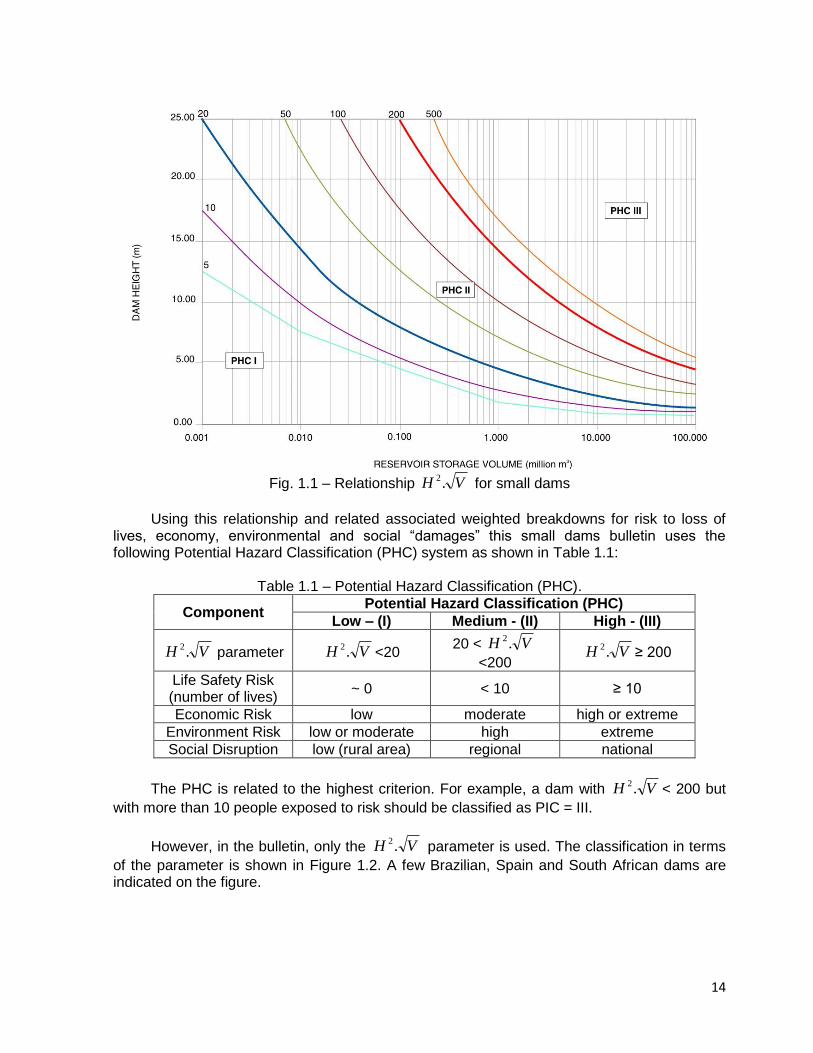
Fig. 1.1 – Relationship VH .2 for small dams
Using this relationship and related associated weighted breakdowns for risk to loss of
lives, economy, environmental and social “damages” this small dams bulletin uses the following Potential Hazard Classification (PHC) system as shown in Table 1.1:
Table 1.1 – Potential Hazard Classification (PHC).
Component Potential Hazard Classification (PHC)
Low – (I) Medium - (II) High - (III)
VH .2 parameter VH .2<20
20 < VH .2
<200 VH .2
≥ 200
Life Safety Risk (number of lives)
~ 0 < 10 ≥ 10
Economic Risk low moderate high or extreme
Environment Risk low or moderate high extreme
Social Disruption low (rural area) regional national
The PHC is related to the highest criterion. For example, a dam with VH .2< 200 but
with more than 10 people exposed to risk should be classified as PIC = III.
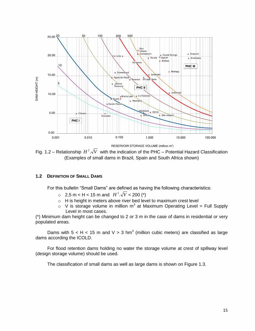
However, in the bulletin, only the VH .2
parameter is used. The classification in terms
of the parameter is shown in Figure 1.2. A few Brazilian, Spain and South African dams are indicated on the figure.
15
Fig. 1.2 – Relationship VH .2 with the indication of the PHC – Potential Hazard Classification
(Examples of small dams in Brazil, Spain and South Africa shown)
1.2 DEFINITION OF SMALL DAMS
For this bulletin “Small Dams” are defined as having the following characteristics:
o 2,5 m < H < 15 m and VH .2< 200 (*)
o H is height in meters above river bed level to maximum crest level o V is storage volume in million m3 at Maximum Operating Level = Full Supply
Level in most cases. (*) Minimum dam height can be changed to 2 or 3 m in the case of dams in residential or very populated areas.
Dams with 5 < H < 15 m and V > 3 hm3 (million cubic meters) are classified as large dams according the ICOLD.
For flood retention dams holding no water the storage volume at crest of spillway level
(design storage volume) should be used.
The classification of small dams as well as large dams is shown on Figure 1.3.
16
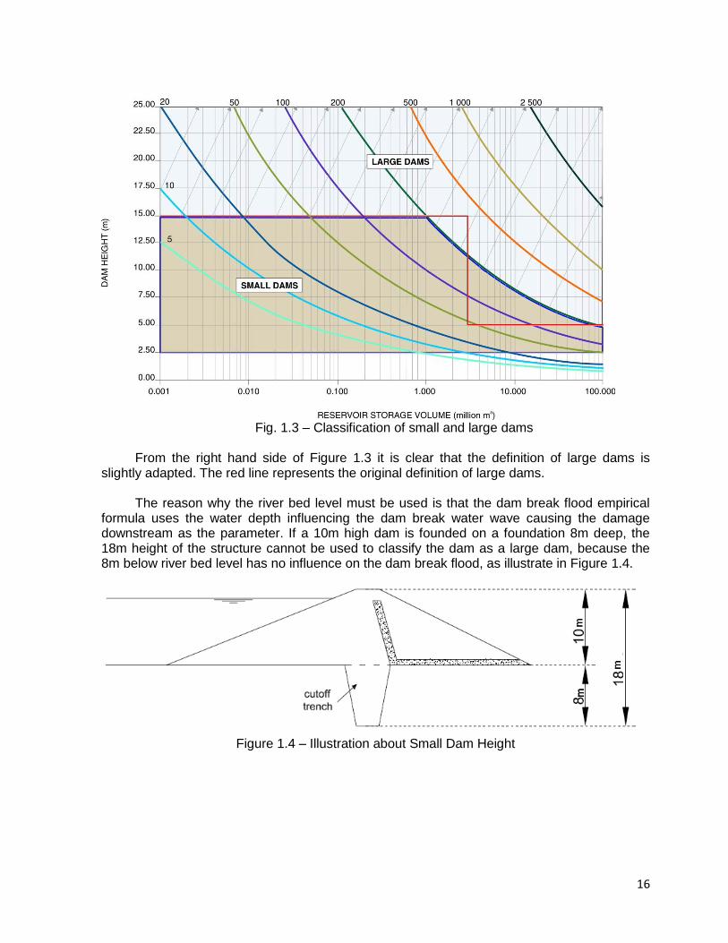
Fig. 1.3 – Classification of small and large dams
From the right hand side of Figure 1.3 it is clear that the definition of large dams is
slightly adapted. The red line represents the original definition of large dams. The reason why the river bed level must be used is that the dam break flood empirical
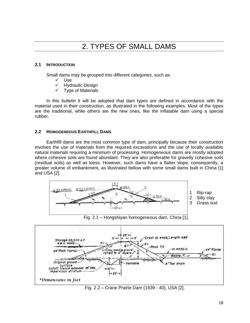
formula uses the water depth influencing the dam break water wave causing the damage downstream as the parameter. If a 10m high dam is founded on a foundation 8m deep, the 18m height of the structure cannot be used to classify the dam as a large dam, because the 8m below river bed level has no influence on the dam break flood, as illustrate in Figure 1.4.
Figure 1.4 – Illustration about Small Dam Height

17
1.3 REFERENCES [1] French Committe on Dams and Reservoirs (1997) Guidelines for Design, Construction,
and Monitoring. Coordinator Gerard Degoutte. ISBN 2-85362-448. [2] ICOLD (1983) – Deterioration of Dams and Reservoir, Report prepared by a team of
Portuguese engineers of the “Laboratory of a Civil Engineering, LNEC, Lisboa; [3] ICOLD (1986) – Soil-Cement for Embankment Dams / Sol-Ciment Pour les Barrages en
Remblai, Bulletin 54 ; [4] ICOLD (1988) – Dam Monitoring General Considerations / Auscultation des Barrages
Considérations Générales, Bulletin 60.
[5] ICOLD (1988) – Inspection of Dams Following Earthquake – Guidelines / Inspection des
Barrages Après Séisme - Recommandations, Bulletin 62.
[6] ICOLD (1990) – Dispersive Soils in Embankment Dams / Sols Dispersifs Dans les
Barrages en Remblai, Bulletin 77.
[7] ICOLD (1992) – Improvement of Existing Dam Monitoring, Recommendations and Case
Histories / Amelioration de L’Auscultation des Barrages, Recommandations et
Exemples, Bulletin 87.
[8] ICOLD (1993) – Embankment Dams Upstream Slope Protection / Barrages en Remblai
Protection du Talus Amont, Bulletin 91.
[9] ICOLD (1994) – Ageing of Dams and Appurtenant Works / Vieillissement des Barrages
et des Ouvrages Annexes, Bulletin 93.
[10] ICOLD (1997) – Dams Less Than Thirty Meters High; Barrages de Moins de 30 m de
Hauteur, Bulletin 109.
[11] ICOLD (2000) – Monitoring of Dams and Their Foundation / Auscultation des Barrages
et des Leurs Fondations, Bulletin 78.
[12] ICOLD (2005) – Risk Assessment in Dam Safety Management / Évaluation du Risque
dans la Gestion de la Sécurité du Barrage, Bulletin 130.
[13] ICOLD (2007) – Dam Surveillance / La Surveillance des Barrages, TCDS Draft Bulletin
No 1 (Rev. 0 - Fev 2007).
[14] CSN 752410 (1997) – "Small Water Reservoirs" , Czech Republic Standard CSN 752410.
18
2. TYPES OF SMALL DAMS
2.1 INTRODUCTION
Small dams may be grouped into different categories, such as:
Use Hydraulic Design Type of Materials
In this bulletin it will be adopted that dam types are defined in accordance with the
material used in their construction, as illustrated in the following examples. Most of the types are the traditional, while others are the new ones, like the inflatable dam using a special rubber.
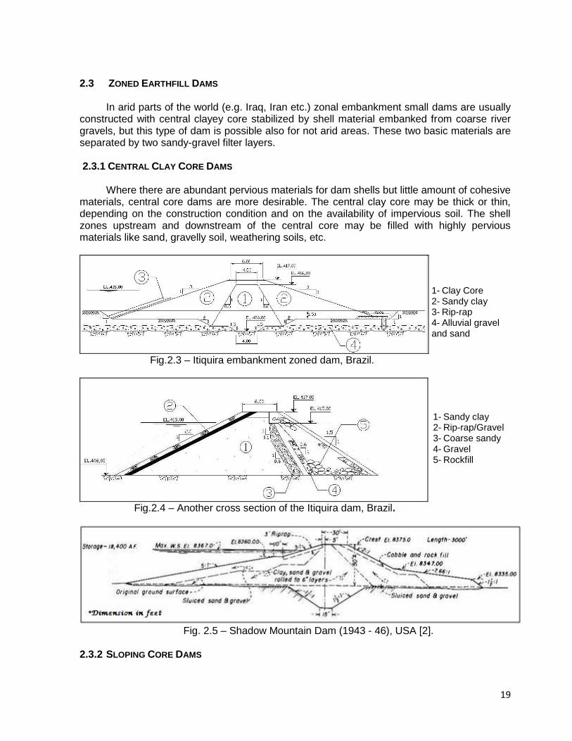
2.2 HOMOGENEOUS EARTHFILL DAMS
Earthfill dams are the most common type of dam, principally because their construction involves the use of materials from the required excavations and the use of locally available natural materials requiring a minimum of processing. Homogeneous dams are mostly adopted where cohesive soils are found abundant. They are also preferable for gravelly cohesive soils (residual soils) as well as loess. However, such dams have a flatter slope, consequently, a greater volume of embankment, as illustrated bellow with some small dams built in China [1] and USA [2].
Fig. 2.1 – Hongshiyan homogeneous dam, China [1].
Fig. 2.2 – Crane Prairie Dam (1939 - 40), USA [2].
1 Rip-rap 2 Silty clay 3 Grass sod
19
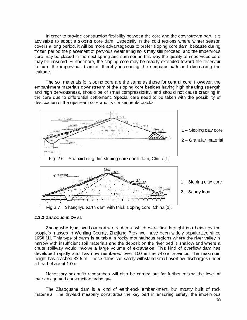
2.3 ZONED EARTHFILL DAMS
In arid parts of the world (e.g. Iraq, Iran etc.) zonal embankment small dams are usually constructed with central clayey core stabilized by shell material embanked from coarse river gravels, but this type of dam is possible also for not arid areas. These two basic materials are separated by two sandy-gravel filter layers.
2.3.1 CENTRAL CLAY CORE DAMS
Where there are abundant pervious materials for dam shells but little amount of cohesive materials, central core dams are more desirable. The central clay core may be thick or thin, depending on the construction condition and on the availability of impervious soil. The shell zones upstream and downstream of the central core may be filled with highly pervious materials like sand, gravelly soil, weathering soils, etc.
Fig.2.3 – Itiquira embankment zoned dam, Brazil.
Fig.2.4 – Another cross section of the Itiquira dam, Brazil.
Fig. 2.5 – Shadow Mountain Dam (1943 - 46), USA [2].
2.3.2 SLOPING CORE DAMS
1- Clay Core 2- Sandy clay 3- Rip-rap 4- Alluvial gravel and sand
1- Sandy clay 2- Rip-rap/Gravel 3- Coarse sandy 4- Gravel 5- Rockfill
20
In order to provide construction flexibility between the core and the downstream part, it is advisable to adopt a sloping core dam. Especially in the cold regions where winter season covers a long period, it will be more advantageous to prefer sloping core dam, because during frozen period the placement of pervious weathering soils may still proceed, and the impervious core may be placed in the next spring and summer, in this way the quality of impervious core may be ensured. Furthermore, the sloping core may be readily extended toward the reservoir to form the impervious blanket, thereby increasing the seepage path and decreasing the leakage.
The soil materials for sloping core are the same as those for central core. However, the
embankment materials downstream of the sloping core besides having high shearing strength and high perviousness, should be of small compressibility, and should not cause cracking in the core due to differential settlement. Special care need to be taken with the possibility of desiccation of the upstream core and its consequents cracks.
Fig. 2.6 – Shanxichong thin sloping core earth dam, China [1].
Fig.2.7 – Shangliyu earth dam with thick sloping core, China [1].
2.3.3 ZHAOGUSHE DAMS
Zhaogushe type overflow earth-rock dams, which were first brought into being by the people’s masses in Wenling County, Zhejiang Province, have been widely popularized since 1958 [1]. This type of dams is suitable in rocky mountainous regions where the river valley is narrow with insufficient soil materials and the deposit on the river bed is shallow and where a chute spillway would involve a large volume of excavation. This kind of overflow dam has developed rapidly and has now numbered over 160 in the whole province. The maximum height has reached 32.5 m. These dams can safely withstand small overflow discharges under a head of about 1.0 m.
Necessary scientific researches will also be carried out for further raising the level of
their design and construction technique. The Zhaogushe dam is a kind of earth-rock embankment, but mostly built of rock
materials. The dry-laid masonry constitutes the key part in ensuring safety, the impervious
1 – Sloping clay core
2 – Granular material
1 – Sloping clay core
2 – Sandy loam
3 – Pervious foundation
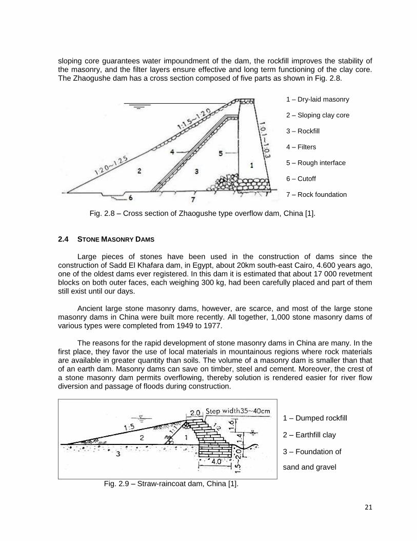
21
sloping core guarantees water impoundment of the dam, the rockfill improves the stability of the masonry, and the filter layers ensure effective and long term functioning of the clay core. The Zhaogushe dam has a cross section composed of five parts as shown in Fig. 2.8.
Fig. 2.8 – Cross section of Zhaogushe type overflow dam, China [1].
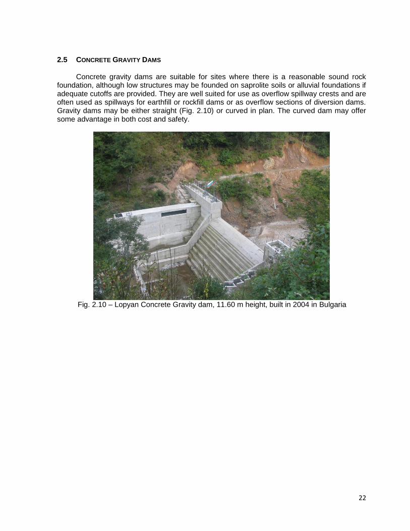
2.4 STONE MASONRY DAMS
Large pieces of stones have been used in the construction of dams since the construction of Sadd El Khafara dam, in Egypt, about 20km south-east Cairo, 4.600 years ago, one of the oldest dams ever registered. In this dam it is estimated that about 17 000 revetment blocks on both outer faces, each weighing 300 kg, had been carefully placed and part of them still exist until our days.
Ancient large stone masonry dams, however, are scarce, and most of the large stone
masonry dams in China were built more recently. All together, 1,000 stone masonry dams of various types were completed from 1949 to 1977.
The reasons for the rapid development of stone masonry dams in China are many. In the
first place, they favor the use of local materials in mountainous regions where rock materials are available in greater quantity than soils. The volume of a masonry dam is smaller than that of an earth dam. Masonry dams can save on timber, steel and cement. Moreover, the crest of a stone masonry dam permits overflowing, thereby solution is rendered easier for river flow diversion and passage of floods during construction.
Fig. 2.9 – Straw-raincoat dam, China [1].
1 – Dry-laid masonry
2 – Sloping clay core
3 – Rockfill
4 – Filters
5 – Rough interface
6 – Cutoff
7 – Rock foundation
1 – Dumped rockfill
2 – Earthfill clay
3 – Foundation of
sand and gravel
22
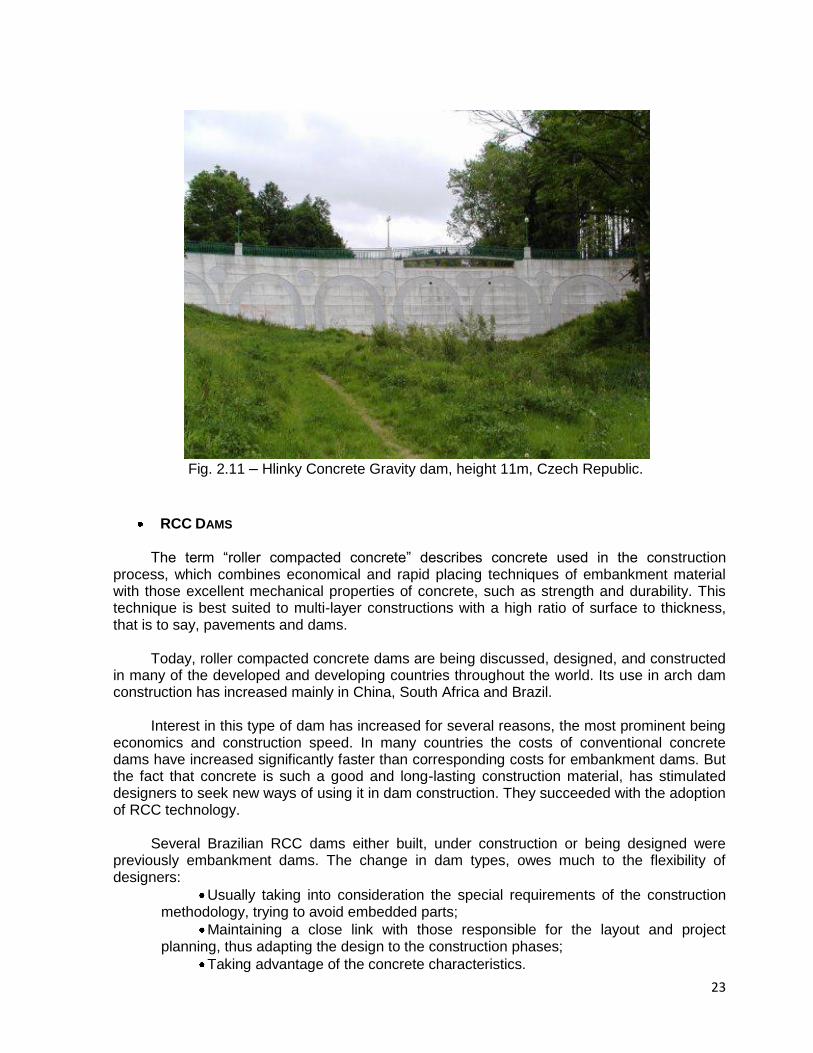
2.5 CONCRETE GRAVITY DAMS Concrete gravity dams are suitable for sites where there is a reasonable sound rock
foundation, although low structures may be founded on saprolite soils or alluvial foundations if adequate cutoffs are provided. They are well suited for use as overflow spillway crests and are often used as spillways for earthfill or rockfill dams or as overflow sections of diversion dams. Gravity dams may be either straight (Fig. 2.10) or curved in plan. The curved dam may offer some advantage in both cost and safety.
Fig. 2.10 – Lopyan Concrete Gravity dam, 11.60 m height, built in 2004 in Bulgaria
23
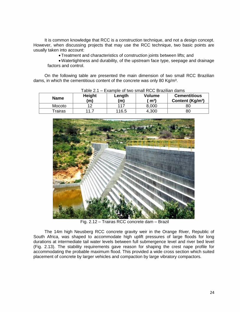
Fig. 2.11 – Hlinky Concrete Gravity dam, height 11m, Czech Republic.
RCC DAMS The term “roller compacted concrete” describes concrete used in the construction
process, which combines economical and rapid placing techniques of embankment material with those excellent mechanical properties of concrete, such as strength and durability. This technique is best suited to multi-layer constructions with a high ratio of surface to thickness, that is to say, pavements and dams.
Today, roller compacted concrete dams are being discussed, designed, and constructed
in many of the developed and developing countries throughout the world. Its use in arch dam construction has increased mainly in China, South Africa and Brazil.
Interest in this type of dam has increased for several reasons, the most prominent being
economics and construction speed. In many countries the costs of conventional concrete dams have increased significantly faster than corresponding costs for embankment dams. But the fact that concrete is such a good and long-lasting construction material, has stimulated designers to seek new ways of using it in dam construction. They succeeded with the adoption of RCC technology.
Several Brazilian RCC dams either built, under construction or being designed were
previously embankment dams. The change in dam types, owes much to the flexibility of designers:
Usually taking into consideration the special requirements of the construction methodology, trying to avoid embedded parts;
Maintaining a close link with those responsible for the layout and project planning, thus adapting the design to the construction phases;
Taking advantage of the concrete characteristics.
24
It is common knowledge that RCC is a construction technique, and not a design concept.
However, when discussing projects that may use the RCC technique, two basic points are usually taken into account:
Treatment and characteristics of construction joints between lifts; and
Watertightness and durability, of the upstream face type, seepage and drainage factors and control.
On the following table are presented the main dimension of two small RCC Brazilian
dams, in which the cementitious content of the concrete was only 80 Kg/m³.
Table 2.1 – Example of two small RCC Brazilian dams
Name Height
(m) Length
(m) Volume
( m³) Cementitious
Content (Kg/m³)
Mocoto 12 117 8,000 80
Trairas 11.7 116.5 4,300 80
Fig. 2.12 – Trairas RCC concrete dam – Brazil
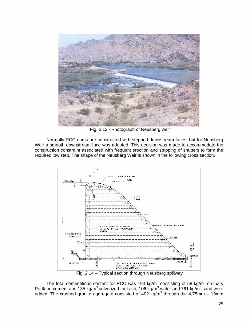
The 14m high Neusberg RCC concrete gravity weir in the Orange River, Republic of
South Africa, was shaped to accommodate high uplift pressures of large floods for long durations at intermediate tail water levels between full submergence level and river bed level (Fig. 2.13). The stability requirements gave reason for shaping the crest nape profile for accommodating the probable maximum flood. This provided a wide cross section which suited placement of concrete by larger vehicles and compaction by large vibratory compactors.
25
Fig. 2.13 - Photograph of Neusberg weir
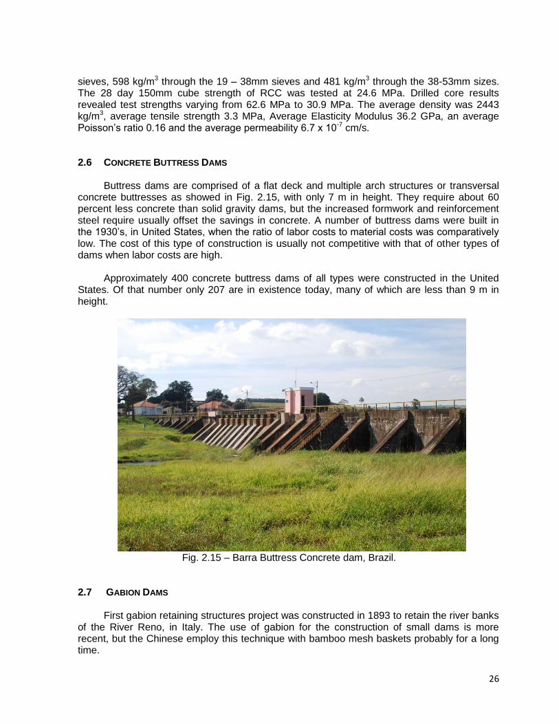
Normally RCC dams are constructed with stepped downstream faces, but for Neusberg Weir a smooth downstream face was adopted. This decision was made to accommodate the construction constraint associated with frequent erection and stripping of shutters to form the required low step. The shape of the Neusberg Weir is shown in the following cross section.
Fig. 2.14 – Typical section through Neusberg spillway
The total cementitious content for RCC was 193 kg/m3 consisting of 58 kg/m3 ordinary Portland cement and 135 kg/m3 pulverized fuel ash, 106 kg/m3 water and 761 kg/m3 sand were added. The crushed granite aggregate consisted of 402 kg/m3 through the 4,75mm – 19mm
26
sieves, 598 kg/m3 through the 19 – 38mm sieves and 481 kg/m3 through the 38-53mm sizes. The 28 day 150mm cube strength of RCC was tested at 24.6 MPa. Drilled core results revealed test strengths varying from 62.6 MPa to 30.9 MPa. The average density was 2443 kg/m3, average tensile strength 3.3 MPa, Average Elasticity Modulus 36.2 GPa, an average Poisson’s ratio 0.16 and the average permeability 6.7 x 10⁻⁷ cm/s.
2.6 CONCRETE BUTTRESS DAMS
Buttress dams are comprised of a flat deck and multiple arch structures or transversal concrete buttresses as showed in Fig. 2.15, with only 7 m in height. They require about 60 percent less concrete than solid gravity dams, but the increased formwork and reinforcement steel require usually offset the savings in concrete. A number of buttress dams were built in the 1930’s, in United States, when the ratio of labor costs to material costs was comparatively low. The cost of this type of construction is usually not competitive with that of other types of dams when labor costs are high.
Approximately 400 concrete buttress dams of all types were constructed in the United
States. Of that number only 207 are in existence today, many of which are less than 9 m in height.
Fig. 2.15 – Barra Buttress Concrete dam, Brazil.
2.7 GABION DAMS
First gabion retaining structures project was constructed in 1893 to retain the river banks
of the River Reno, in Italy. The use of gabion for the construction of small dams is more recent, but the Chinese employ this technique with bamboo mesh baskets probably for a long time.
27
The gabion dam as the gabion retaining structures employ generally wire mesh baskets filled with rock at the downstream part of the dam to form a flexible, permeable, monolithic structure similar to a gabion retaining wall. At the upstream part is compacted an earthfill as the impervious element.
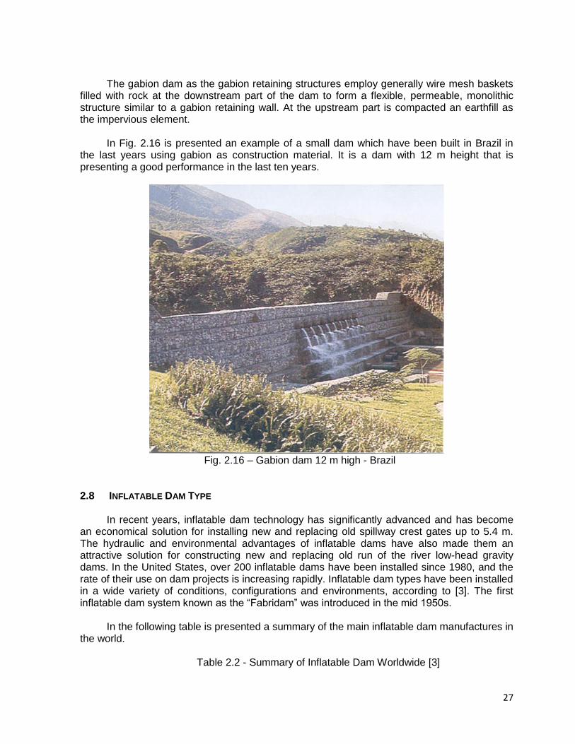
In Fig. 2.16 is presented an example of a small dam which have been built in Brazil in
the last years using gabion as construction material. It is a dam with 12 m height that is presenting a good performance in the last ten years.
Fig. 2.16 – Gabion dam 12 m high - Brazil
2.8 INFLATABLE DAM TYPE
In recent years, inflatable dam technology has significantly advanced and has become
an economical solution for installing new and replacing old spillway crest gates up to 5.4 m. The hydraulic and environmental advantages of inflatable dams have also made them an attractive solution for constructing new and replacing old run of the river low-head gravity dams. In the United States, over 200 inflatable dams have been installed since 1980, and the rate of their use on dam projects is increasing rapidly. Inflatable dam types have been installed in a wide variety of conditions, configurations and environments, according to [3]. The first inflatable dam system known as the “Fabridam” was introduced in the mid 1950s.
In the following table is presented a summary of the main inflatable dam manufactures in
the world.
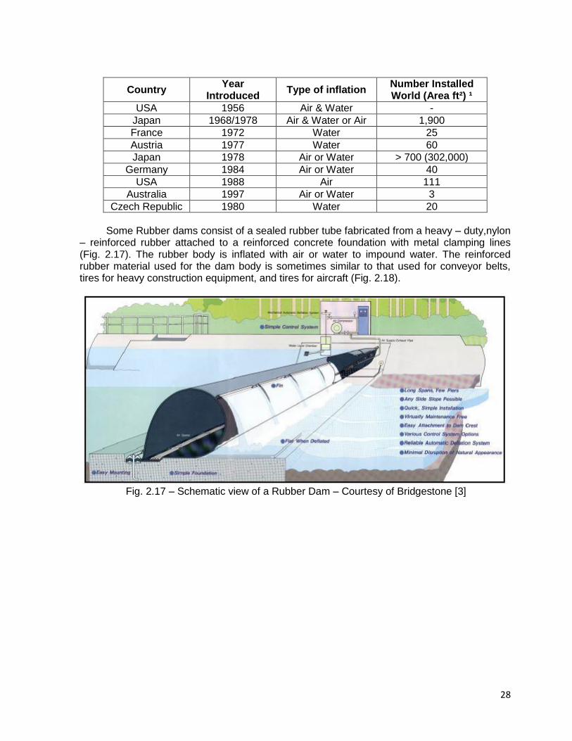
Table 2.2 - Summary of Inflatable Dam Worldwide [3]
28
Country Year
Introduced Type of inflation
Number Installed World (Area ft²) ¹
USA 1956 Air & Water -
Japan 1968/1978 Air & Water or Air 1,900
France 1972 Water 25
Austria 1977 Water 60
Japan 1978 Air or Water > 700 (302,000)
Germany 1984 Air or Water 40
USA 1988 Air 111
Australia 1997 Air or Water 3
Czech Republic 1980 Water 20
Some Rubber dams consist of a sealed rubber tube fabricated from a heavy – duty,nylon
– reinforced rubber attached to a reinforced concrete foundation with metal clamping lines (Fig. 2.17). The rubber body is inflated with air or water to impound water. The reinforced rubber material used for the dam body is sometimes similar to that used for conveyor belts, tires for heavy construction equipment, and tires for aircraft (Fig. 2.18).
Fig. 2.17 – Schematic view of a Rubber Dam – Courtesy of Bridgestone [3]
29
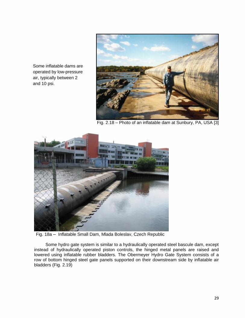
Fig. 2.18 – Photo of an inflatable dam at Sunbury, PA, USA [3]
Fig. 18a – Inflatable Small Dam, Mlada Boleslav, Czech Republic
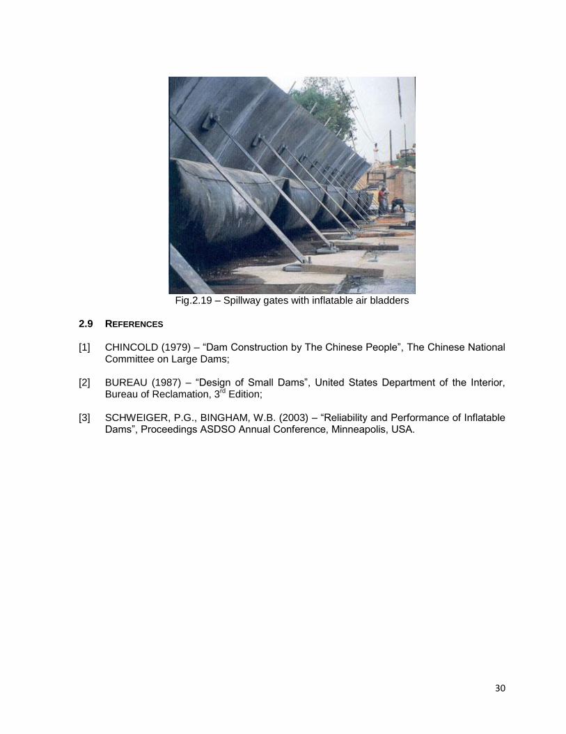
Some hydro gate system is similar to a hydraulically operated steel bascule dam, except
instead of hydraulically operated piston controls, the hinged metal panels are raised and lowered using inflatable rubber bladders. The Obermeyer Hydro Gate System consists of a row of bottom hinged steel gate panels supported on their downstream side by inflatable air bladders (Fig. 2.19)
Some inflatable dams are
operated by low-pressure
air, typically between 2
and 10 psi.
30
Fig.2.19 – Spillway gates with inflatable air bladders
2.9 REFERENCES
[1] CHINCOLD (1979) – “Dam Construction by The Chinese People”, The Chinese National
Committee on Large Dams; [2] BUREAU (1987) – “Design of Small Dams”, United States Department of the Interior,
Bureau of Reclamation, 3rd Edition; [3] SCHWEIGER, P.G., BINGHAM, W.B. (2003) – “Reliability and Performance of Inflatable
Dams”, Proceedings ASDSO Annual Conference, Minneapolis, USA.
31
3. SAFETY OF SMALL DAMS 3.1 INTRODUCTION
In this chapter are discussed the peculiarities and conditions affecting the safety of small dams. In comparison with large dams most dam engineering criteria and practices apply to small dams. The following differences between large and small dam practices are applicable:
Lower water, sedimentation and gravitational loads are applicable and therefore lower stresses and strains in the structures and on the foundation are to be taken into consideration in the design;
Economics play a very important role because decisions are taken with financial constraints as background. This could lead to design criteria and construction methods with higher risk, more maintenance problems and in some cases to catastrophic failure.
The time required by engineers for small dam design and construction monitoring is as time consuming as for large dam activities, although due to cost constraints significantly less time is approved for technical services by clients of small dams. This leads to savings in investigation, design and site monitoring costs, which leads to substandard designs and construction quality achieved during construction. Proper designs must therefore be done and construction monitoring ensuring quality must not be limited.
Foundation and construction materials investigations are normally limited due to financial constraints, with normally higher cost to the structure due to unknown conditions. Proper investigations tailored to the specific foundation and construction materials for the required dams are therefore necessary.
Flood Hydrological investigations are sometimes limited with catastrophic consequences if the dams are overtopped.
Normal seepage rates may impact on the yield of small dams. And low water depth makes small reservoirs more sensitive to evaporation. Higher care must therefore be taken to seepage control (reduction) measures.
Often inexperienced small contractors are used to construct small dams. These contractors have limited resources and sometimes use “farm dam” practices to construct with a low quality structure and poor performance.
Dambreak floods caused by smaller dams are lower in size due to the lower water head and water volume in the dams. The potential loss of life and damages are lower. Due to this, lower design standards are applied for many aspects e.g. spillway sizing. Despite this fact, the number of victims is generally significant as a consequence of the great number of small dams and the large number of failures during extreme floods.

32
One dam failing in a cascade of dams in a river system may cause the other downstream dams to fail.
It is acceptable to design for higher risk of failure for floods, e.g. overtopping with flood occurrences associated with lower recurrence intervals.
3.2 CONDITIONS AFFECTING THE SAFETY Examples of conditions affecting the safety of existing small dams as well as reasons
for dam failure are summarized in Table 3.1.
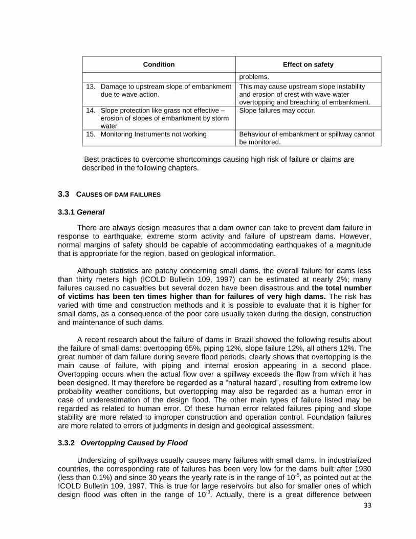
Table 3.1 - Examples of conditions affecting the safety of existing embankment dams
Condition Effect on safety
1. Inadequate spillway capacity (dam flood handling capacity) caused by too small spillway, heightening of the spillway crest by owners not aware of the hydrologic risks, too little freeboard or obstructions in spillway e.g. tree growth.
Embankment can be overtopped and breached.
2. Backward erosion of erodible by-wash spillways.
Erosion channel can extend into dam reservoir with consequential dam failure through the spillway.
3. Uneven crest of embankment (it may be constructed uneven or settle). Cattle footpath provides low point on crest of embankment.
Embankment can be overtopped and breached due to concentration of water in the low crest areas.
4. Wet areas or seepage through embankment or foundation, as identified on downstream face or in area downstream of embankment.
Saturated conditions in the downstream shell can cause slope failure. Piping failure of embankment can occur.
5. Obstruction of the internal drainage system.
Phreatic surface may be raised by blocked drains.
6. No internal drains and filters provided – especially for embankments constructed with dispersive clays.
Piping failure can occur, most of them during the first reservoir filling
7. High seepage water along or into outlet pipe – conduit pipes may crack due to settlement or the pipe materials may degrade e.g. wooden pipes exposed to air and water.
Piping failure of embankment along bottom outlet can occur.
8. Piping (or internal erosion) at the interface of an embankment and retaining wall for the spillway control section and/or “start” of the spillway return channel.
Embankment can breach at that point
9. Embankment cracks or slope failures occur Embankment breaching failure can occur.
10. Tree growth on embankments – roots damaging the embankment especially when dead.
Piping failure of embankment can occur.
11. Burrowing animals excavate tunnels in embankment.
Embankment slope failure or seepage failure may occur.
12. Compaction of earthfill not meeting standard
Uncompacted embankments experience settlement, seepage and slope failure
33
Condition Effect on safety
problems.
13. Damage to upstream slope of embankment due to wave action.
This may cause upstream slope instability and erosion of crest with wave water overtopping and breaching of embankment.
14. Slope protection like grass not effective – erosion of slopes of embankment by storm water
Slope failures may occur.
15. Monitoring Instruments not working
Behaviour of embankment or spillway cannot be monitored.
Best practices to overcome shortcomings causing high risk of failure or claims are described in the following chapters.
3.3 CAUSES OF DAM FAILURES
3.3.1 General
There are always design measures that a dam owner can take to prevent dam failure in response to earthquake, extreme storm activity and failure of upstream dams. However, normal margins of safety should be capable of accommodating earthquakes of a magnitude that is appropriate for the region, based on geological information.
Although statistics are patchy concerning small dams, the overall failure for dams less
than thirty meters high (ICOLD Bulletin 109, 1997) can be estimated at nearly 2%; many failures caused no casualties but several dozen have been disastrous and the total number of victims has been ten times higher than for failures of very high dams. The risk has varied with time and construction methods and it is possible to evaluate that it is higher for small dams, as a consequence of the poor care usually taken during the design, construction and maintenance of such dams.
A recent research about the failure of dams in Brazil showed the following results about the failure of small dams: overtopping 65%, piping 12%, slope failure 12%, all others 12%. The great number of dam failure during severe flood periods, clearly shows that overtopping is the main cause of failure, with piping and internal erosion appearing in a second place. Overtopping occurs when the actual flow over a spillway exceeds the flow from which it has been designed. It may therefore be regarded as a “natural hazard”, resulting from extreme low probability weather conditions, but overtopping may also be regarded as a human error in case of underestimation of the design flood. The other main types of failure listed may be regarded as related to human error. Of these human error related failures piping and slope stability are more related to improper construction and operation control. Foundation failures are more related to errors of judgments in design and geological assessment. 3.3.2 Overtopping Caused by Flood
Undersizing of spillways usually causes many failures with small dams. In industrialized
countries, the corresponding rate of failures has been very low for the dams built after 1930 (less than 0.1%) and since 30 years the yearly rate is in the range of 10-5, as pointed out at the ICOLD Bulletin 109, 1997. This is true for large reservoirs but also for smaller ones of which design flood was often in the range of 10-3. Actually, there is a great difference between
34
specific exceptional flood around the world and the following table lists order of magnitude (but not maximum) 10 000 year flood flows for different climates and catchment area. Table 3.2 – Order-of-magnitude ten thousand year flood discharge in m3/s (Bulletin 109, 1997)
Catchment Area (km2) 2 km2 10 km2 50 km2
Climates with moderate rainfall (Northern Europe, Russia, Canada, North-West USA)
10 30 100
Intermediate climates (Mediterranean, Central America, South America)
30 100 300
Climates with extreme rainfall (South and East Asia) 100 300 1000
Worldwide Maximum of registered values 200 700 2000
In some cases, the overtopping causes a general sliding of the downstream part of the
dam embankment then a rather large initial breach. But in most cases, the initial breach resulting from the toe erosion is relatively narrow, as in case of piping, and may or not widen according to cross section and materials characteristics. For a same dam and same initial plan of breach, breach flow is higher for overtopping than for piping, due to higher water level and arriving flow.
Over 3% of dam failures occurred due to the failure of a dam further upstream. This risk
should not be overlooked in the coming years for both existing and new dams. Nor should partial obstruction of the spillways by vegetation or floating debris be forgotten.
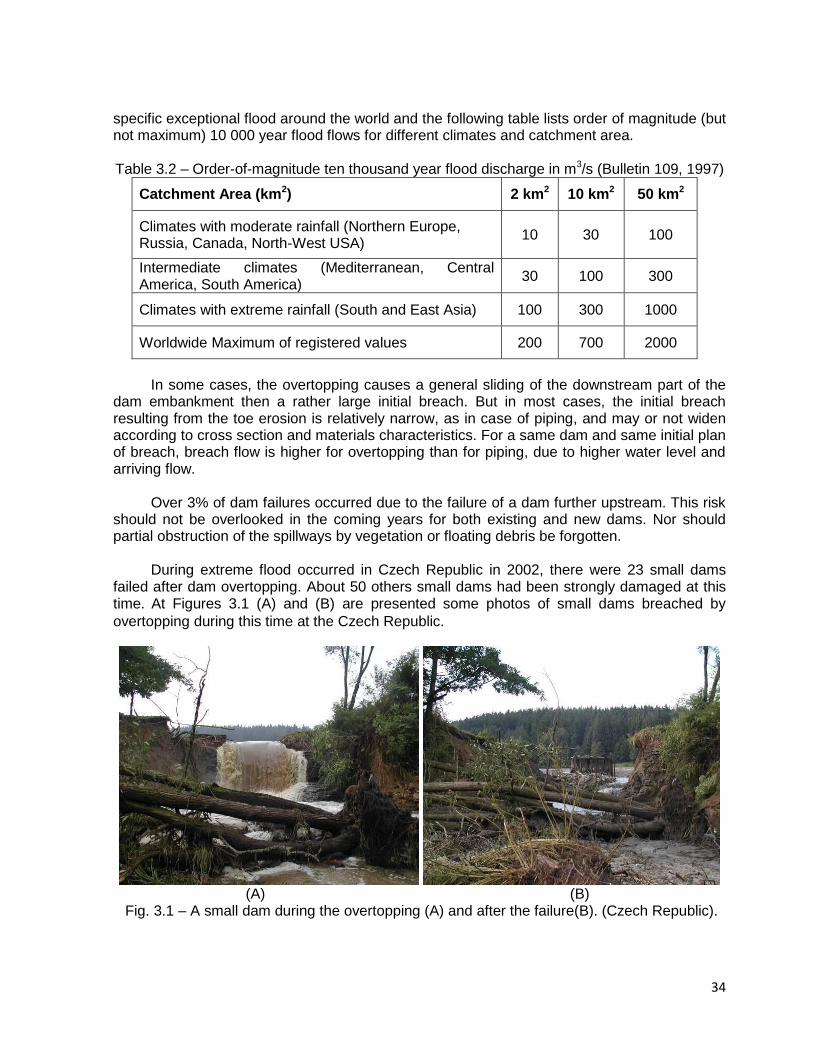
During extreme flood occurred in Czech Republic in 2002, there were 23 small dams
failed after dam overtopping. About 50 others small dams had been strongly damaged at this time. At Figures 3.1 (A) and (B) are presented some photos of small dams breached by
overtopping during this time at the Czech Republic.
(A) (B)
Fig. 3.1 – A small dam during the overtopping (A) and after the failure(B). (Czech Republic).
35
Fig. 3.2 – Massive dam break overtopping, during extremely high floods in the Czech
Republic.
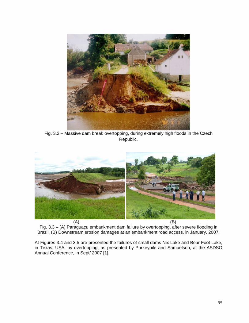
(A) (B)
Fig. 3.3 – (A) Paraguaçu embankment dam failure by overtopping, after severe flooding in Brazil. (B) Downstream erosion damages at an embankment road access, in January, 2007.
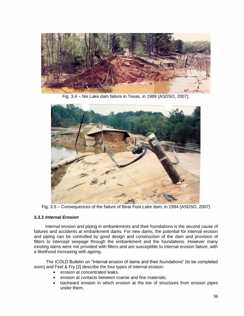
At Figures 3.4 and 3.5 are presented the failures of small dams Nix Lake and Bear Foot Lake, in Texas, USA, by overtopping, as presented by Purkeypile and Samuelson, at the ASDSO Annual Conference, in Sept/ 2007 [1].
36
Fig. 3.4 – Nix Lake dam failure in Texas, in 1989 (ASDSO, 2007).
Fig. 3.5 – Consequences of the failure of Bear Foot Lake dam, in 1994 (ASDSO, 2007)
3.3.3 Internal Erosion
Internal erosion and piping in embankments and their foundations is the second cause of failures and accidents at embankment dams. For new dams, the potential for internal erosion and piping can be controlled by good design and construction of the dam and provision of filters to intercept seepage through the embankment and the foundations. However many existing dams were not provided with filters and are susceptible to internal erosion failure, with a likelihood increasing with ageing.
The ICOLD Bulletin on “Internal erosion of dams and their foundations” (to be completed
soon) and Feel & Fry [2] describe the four types of internal erosion:
erosion at concentrated leaks,
erosion at contacts between coarse and fine materials,
backward erosion in which erosion at the toe of structures from erosion pipes under them,
37
and suffusion or internal instability, which may occur in gap-graded materials where the soil fabric is such that small particles can be eroded out between larger particles.
In any case, internal erosion is due to non controlled seepage through the embankment,
through the foundation or at a transition between the embankment (or foundation) and a rigid
structure (spillway, bottom outlet, etc).
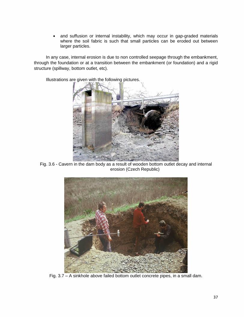
Illustrations are given with the following pictures.
Fig. 3.6 - Cavern in the dam body as a result of wooden bottom outlet decay and internal
erosion (Czech Republic)
Fig. 3.7 – A sinkhole above failed bottom outlet concrete pipes, in a small dam.
38
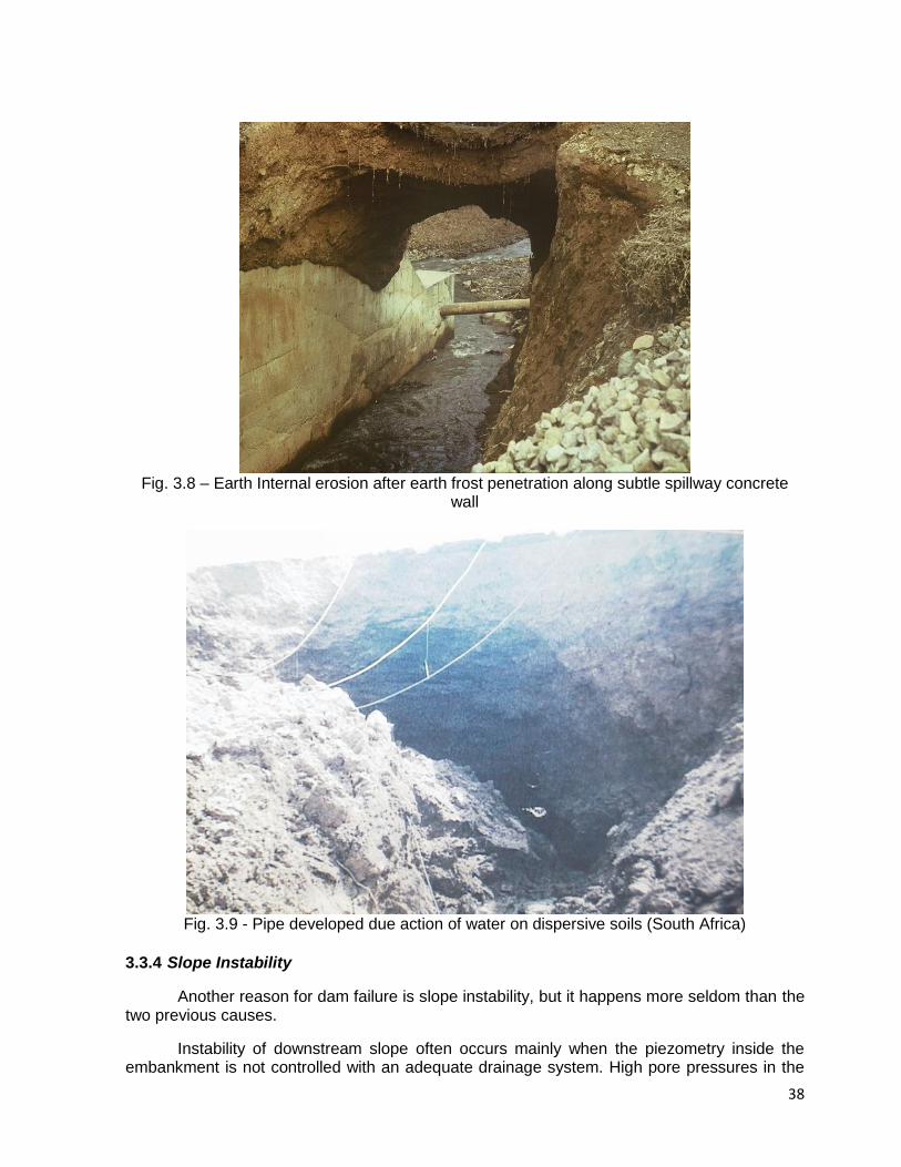
Fig. 3.8 – Earth Internal erosion after earth frost penetration along subtle spillway concrete
wall
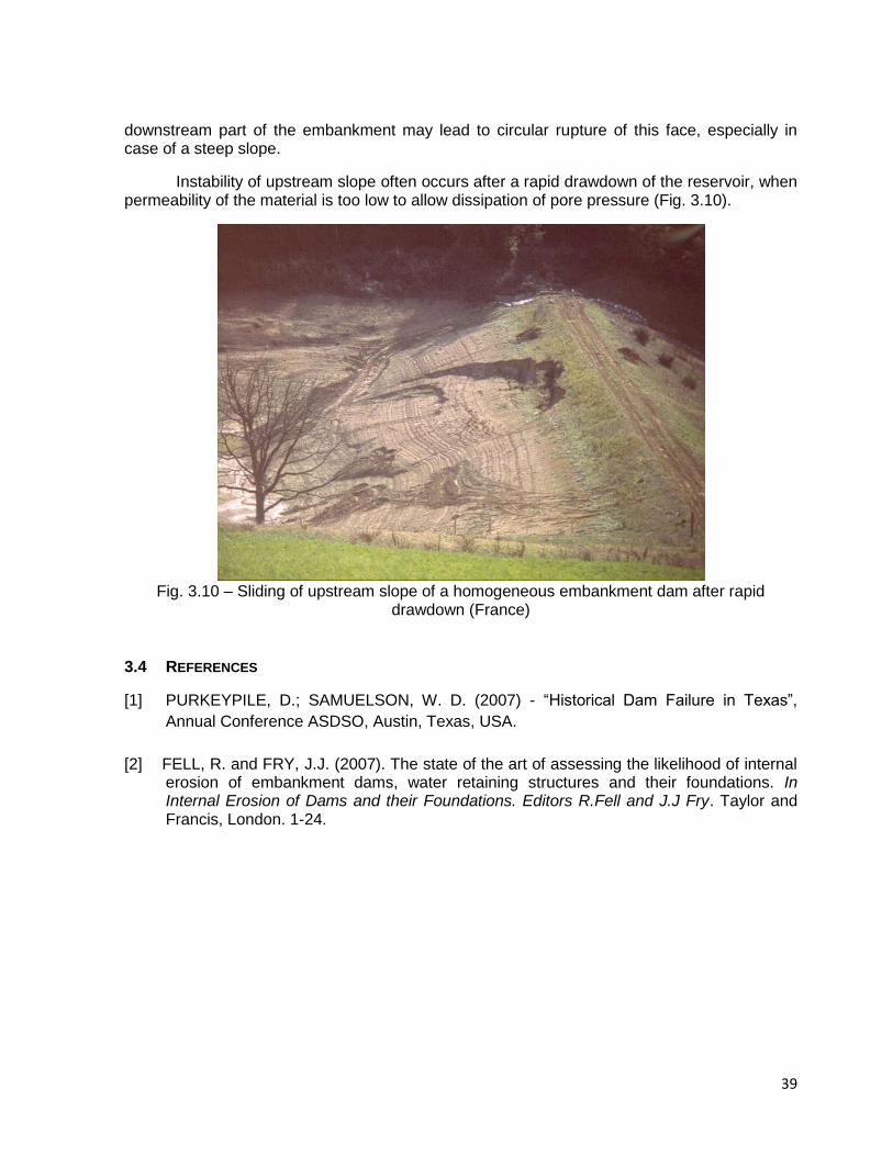
Fig. 3.9 - Pipe developed due action of water on dispersive soils (South Africa)
3.3.4 Slope Instability
Another reason for dam failure is slope instability, but it happens more seldom than the two previous causes.
Instability of downstream slope often occurs mainly when the piezometry inside the embankment is not controlled with an adequate drainage system. High pore pressures in the
39
downstream part of the embankment may lead to circular rupture of this face, especially in case of a steep slope.
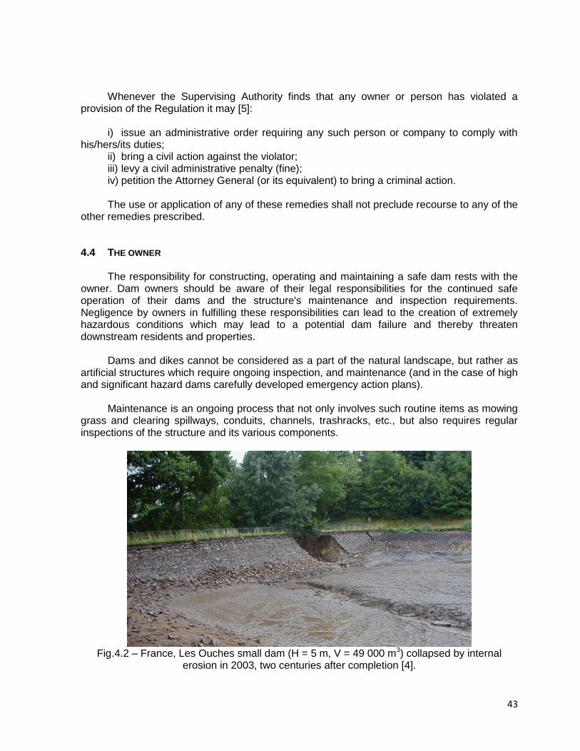
Instability of upstream slope often occurs after a rapid drawdown of the reservoir, when permeability of the material is too low to allow dissipation of pore pressure (Fig. 3.10).
Fig. 3.10 – Sliding of upstream slope of a homogeneous embankment dam after rapid
drawdown (France)
3.4 REFERENCES
[1] PURKEYPILE, D.; SAMUELSON, W. D. (2007) - “Historical Dam Failure in Texas”,
Annual Conference ASDSO, Austin, Texas, USA.
[2] FELL, R. and FRY, J.J. (2007). The state of the art of assessing the likelihood of internal erosion of embankment dams, water retaining structures and their foundations. In Internal Erosion of Dams and their Foundations. Editors R.Fell and J.J Fry. Taylor and Francis, London. 1-24.

40
4. LEGISLATION & DECOMMISSIONING
4.1 INTRODUCTION
As a general rule, protection of persons and property is a responsibility of the Government, who must legislate (create regulation) and enforce the rules through administrative bodies (agency, department, office etc) to provide for the safety and security of the people, property and environment. That is why dam design, construction, rehabilitation, enlargement, alteration, operation, monitoring, maintenance, repair, breach, abandonment and removal must rely on a legal frame that establishes rights, responsibilities and duties of the parties involved [1].
Failure of a dam, even a small one, can result in fatalities, loss of water supply, property destruction and environmental damage.
Fig. 4.1 – Busek pond in Czech Republic – dam break after overtopping in August 1991
(extreme summer raining) [2]. International experience shows higher risk from small, rural dams rather than from
larger, well-engineered dams [3]. According to the Bureau of Reclamation of the USA, 87% of the victims of dam disasters were related to small dam failures, between 1970 and 1997.
Therefore, it is paramount that Governments clearly define the responsibilities of the
owner and establish a regulatory body with dam safety as its primary concern, completely independent from entities currently owning, operating or using dams.
4.2 THE REGULATION
Regulation must cover dams and levees in a coherent manner, and the basic framework should be the same for all dams, regardless of whether they are for electricity production, water supply, irrigation, flood control or other purposes.
Requirements for dams should vary on the basis of dam and reservoir size. Size is
based on criteria combining dam height and reservoir capacity, being intuitively true that a

41
small dam impounding a lot of water may be as much of a danger as a high dam impounding little water.
Recent changes in French regulation changed in 2007 the dam classification system,
introducing a graded system with four classes of dams [4]:
A: m20H
B: 10 < H < 20 m and 200VH 2 (V in hm3)
C: 5 < H < 10 m and 20VH 2
D: 2 < H < 5 m The authorities may in some cases modify the classification if there are special
circumstances. The new French classification replaces the all-or-nothing system, whereby dams listed
as a potential danger to public safety absorb massive supervision and monitoring resources, while others are frequently ignored. It must be acknowledged by Governments that even small dams are not without risks.
According to the above referred graded system, responsibilities and requirements are
defined as it will be further explained. The USA Model Law for State Supervision of Safety of Dams and Reservoirs adopts a
different classification system. According to this Model Law, the Dams are defined as any artificial barrier with ability to impound water and which is: H ≥ 7,5 m and V > 18,450 m3, or V ≥ 61,500 m3 and H > 2 m (please note that in the USA this type of dam regulation is a State matter, not a Federal one, and in some States we may find different definitions according to their own experience and needs).
The American Model establishes a Hazard Potential classification that does not reflect in
any way on the current condition of the dam (safety, structural integrity etc), but in the possible adverse consequences of the release of stored water due to failure or mis-operation of the dam [6]:
I) High Hazard Potential Dam: dam’s failure or mis-operation will probably cause loss
of human life (even if it is only one person); II) Significant Hazard Potential Dam: no probable loss of human life but can cause
major economic loss, environmental damage, disruption of lifeline facilities, or impact other concerns;
III) Low Hazard Potential Dam: no probable loss of human life and low economic and/or environmental losses (losses mostly limited to owner’s property).
Regardless of which classification system each country adopts, it is important that the
Regulation establishes a Risk Prioritization Criteria and based on this classification, defines responsibilities and requirements.
4.3 THE SUPERVISING AUTHORITY
A unit of the Government must be designated by law to be responsible for implementation and administration of the Regulation. The Supervising Authority shall be

42
administered and directed by someone clearly qualified by training and experience in the issue of dam safety.
The Supervising Authority is responsible for enforcing the Regulation and ensuring that
the Owner complies with his responsibilities; this means that the staff in charge of the supervision must possess sufficient skills and knowledge to be able to judge if the Owner’s efforts are commensurate to his duties.
Initially the Supervising Authority or the Owners (depending of the country regulation)
should conduct an inventory of dams to determine: a) name and address of the owner; b) the location, type, size, purpose and height of the dam; c) storage capacity; d) as accurately as may be readily obtained, the area of the drainage basin, rainfall and stream flow records, flood-flow records and estimates; e) classification of the dam according to the hazard potential risk. Based on this inventory, the Supervising Authority shall classify the dams according to
their risk (potential and present) and identify the small dams with a high risk accordingly to the Risk Prioritization Criteria.
The total number of small dams to be submitted to surveillance by an inspector cannot
be excessive, in order that each dam shall have its safety conditions appropriately checked. Also, it is suggested that the dam inspectors exchange their experience, periodically participating in workshops and seminars.
In France, the regional supervisors shall have the support of teams of specialists
(engineers with experience in civil, geotechnical, hydraulic, hydrological and risk engineering applied to water-retaining works) operating nationwide[4].
Table 4.1 – Duties involved according into the French dam classes
ITEM A B C D
Technical and administrative approval
yes yes yes yes
Attendance at foundation excavation acceptance inspection
recommended recommended possible no
Inspection of completed scheme and verification of conformity
yes yes yes no
Approval of operating surveillance procedures
yes yes yes no
Periodic inspection 1 year 1 to 5 years 1 to 10 years no
Obs. - Please see item 4.2 above for the French dam classification system.
The Supervising Authority also shall have the power to adopt rules, standards and requirements for the design, construction, reconstruction, enlargement, alteration, operation, monitoring, maintenance, modification, repair, breach, abandonment and removal of dams and reservoirs to carry out the purpose of the Regulation.
To exemplify some of the responsibilities of this Authority in practical terms, the following
table presents the duties of this body in France regarding their four dam classes [4]:
43
Whenever the Supervising Authority finds that any owner or person has violated a
provision of the Regulation it may [5]: i) issue an administrative order requiring any such person or company to comply with
his/hers/its duties; ii) bring a civil action against the violator; iii) levy a civil administrative penalty (fine); iv) petition the Attorney General (or its equivalent) to bring a criminal action. The use or application of any of these remedies shall not preclude recourse to any of the
other remedies prescribed.
4.4 THE OWNER
The responsibility for constructing, operating and maintaining a safe dam rests with the owner. Dam owners should be aware of their legal responsibilities for the continued safe operation of their dams and the structure's maintenance and inspection requirements. Negligence by owners in fulfilling these responsibilities can lead to the creation of extremely hazardous conditions which may lead to a potential dam failure and thereby threaten downstream residents and properties.
Dams and dikes cannot be considered as a part of the natural landscape, but rather as
artificial structures which require ongoing inspection, and maintenance (and in the case of high and significant hazard dams carefully developed emergency action plans).
Maintenance is an ongoing process that not only involves such routine items as mowing
grass and clearing spillways, conduits, channels, trashracks, etc., but also requires regular inspections of the structure and its various components.
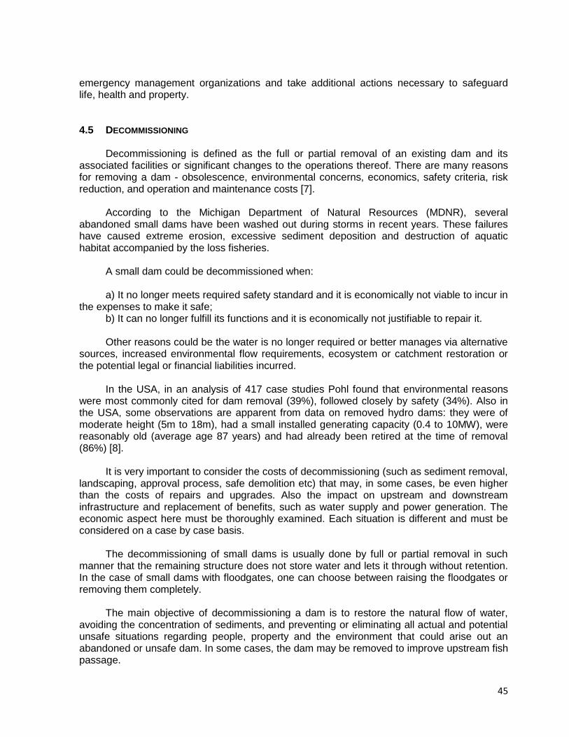
Fig.4.2 – France, Les Ouches small dam (H = 5 m, V = 49 000 m3) collapsed by internal
erosion in 2003, two centuries after completion [4].

44
The legal definition of Owner shall be broad in such a way that includes any person who own, control, operate, maintain, manage or propose to construct, rehabilitate, enlarge, repair, alter, remove or abandon a dam or reservoir.
Regulation shall require that permits be obtained by Owners to construct, repair or alter
dams, dikes or similar structures and that Owners demonstrate that existing dams are being properly maintained and meet modern safety standards, and include specific responsibilities a dam Owner must implement to ensure ongoing safety. Measures include:
Requirements for record keeping (design plant, permanent reference points,
embedded instruments location and readings etc); Inspection and maintenance plans; Scheduled inspections by a professional engineer working for the owner; Scheduled safety reassessments to confirm that a dam meets up to date safety criteria; Emergency action plans to all dams with a high hazard rating; Disclosing the presence of a dam when property is transferred; Periodical review of a dam's hazard classification; Demonstration of financial assurance, collectible if the state is forced to conduct
necessary remedial work at a dam; and Annual certification that the dam's inspection and maintenance plan, emergency action
plan, and other requirements are being met, for all small dams with a high hazard rating. The following table summarizes the duties of dam Owners and Concession Holders in
France [4] for their four dam classes (as mentioned on item 4.2 above):
Table 4.2 – Duties of dam Owners and the Concession Holders in France.
A B C D
Complete record of dam design, construction and service life
yes yes yes yes
Register yes yes yes yes
Detailed technical inspection 1 year 2 years 5 years 10 years
Operator's report 1 year ≤ 5 years ≤ 5 years no
Instrumentation report 2 years ≤ 5 years ≤ 5 years no
Operating rules (normal operation and flood period)
yes yes yes yes
New design or modifications to be submitted to Permanent Committee on Dams and Water-Retaining Structures
yes no no no
Ten-year safety review including full technical inspection
yes no no no
Hazard study yes yes no no
Report any significant events yes yes yes yes
In order to protect life and property, Owners of high potential hazard small dams should
develop, and periodically test and update, an Emergency Action Plan (EAP) that shall be implemented in the event of an emergency involving their dam.
Owners of dams and reservoirs have the primary responsibility for determining when an
emergency involving a dam/reservoir exists. When facing an emergency, the Owner shall implement the EAP, notify any persons who may be endangered if the dam should fail, notify
45
emergency management organizations and take additional actions necessary to safeguard life, health and property.
4.5 DECOMMISSIONING
Decommissioning is defined as the full or partial removal of an existing dam and its associated facilities or significant changes to the operations thereof. There are many reasons for removing a dam - obsolescence, environmental concerns, economics, safety criteria, risk reduction, and operation and maintenance costs [7].
According to the Michigan Department of Natural Resources (MDNR), several
abandoned small dams have been washed out during storms in recent years. These failures have caused extreme erosion, excessive sediment deposition and destruction of aquatic habitat accompanied by the loss fisheries.
A small dam could be decommissioned when: a) It no longer meets required safety standard and it is economically not viable to incur in
the expenses to make it safe; b) It can no longer fulfill its functions and it is economically not justifiable to repair it. Other reasons could be the water is no longer required or better manages via alternative
sources, increased environmental flow requirements, ecosystem or catchment restoration or the potential legal or financial liabilities incurred.
In the USA, in an analysis of 417 case studies Pohl found that environmental reasons
were most commonly cited for dam removal (39%), followed closely by safety (34%). Also in the USA, some observations are apparent from data on removed hydro dams: they were of moderate height (5m to 18m), had a small installed generating capacity (0.4 to 10MW), were reasonably old (average age 87 years) and had already been retired at the time of removal (86%) [8].
It is very important to consider the costs of decommissioning (such as sediment removal,
landscaping, approval process, safe demolition etc) that may, in some cases, be even higher than the costs of repairs and upgrades. Also the impact on upstream and downstream infrastructure and replacement of benefits, such as water supply and power generation. The economic aspect here must be thoroughly examined. Each situation is different and must be considered on a case by case basis.
The decommissioning of small dams is usually done by full or partial removal in such
manner that the remaining structure does not store water and lets it through without retention. In the case of small dams with floodgates, one can choose between raising the floodgates or removing them completely.
The main objective of decommissioning a dam is to restore the natural flow of water,
avoiding the concentration of sediments, and preventing or eliminating all actual and potential unsafe situations regarding people, property and the environment that could arise out an abandoned or unsafe dam. In some cases, the dam may be removed to improve upstream fish passage.
46
The suspended solids contained in runoff tend to settle in the quiescent reservoir waters. In industrialized areas these sediments may contain contamination such as metals, oil and grease and many other chemicals. In rural areas these sediments may contain contaminants such as pesticides and herbicides from agricultural operations. The quantity and concentration of sediments, and the rate at which they will be returned to the fluvial system are also a major concern.
Sediment disposal is a significant issue to be resolved when considering dam
decommissioning. The sediments regularly concentrated in the bottom of the reservoir could require adequate treatment or removal to avoid environmental damage downstream.
Removal of the saturated sediments from the reservoir and disposing of it on land is
expensive. Therefore, allowing the sediments to be flushed downstream as a dam is removed has been the most common practice to-date in the USA. This method has a detrimental effect on the water quality; however, the streams restore themselves after a period of time after the flushing has been allowed. This method has been used on small dams and has also been proposed for large dam decommissioning [9].
The decommissioning can be proposed by the owner or by the regulator and should be
approved by the competent Authority responsible for dam safety. After the approval, a project plan must be prepared in accordance to the regulation.
The owner of the small dam should draft a decommissioning project plan in order to
avoid any situation of risk when the dam is abandoned upon completion of the concession/authorization period or due to lack of maintenance and conservation.
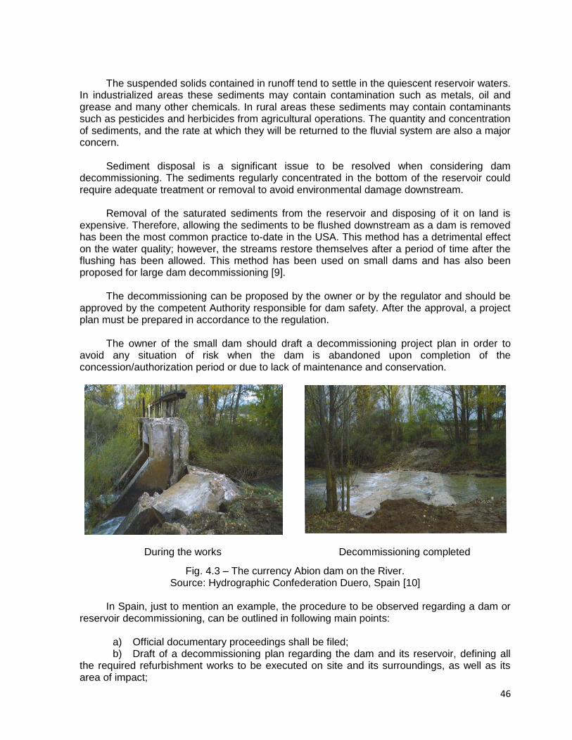
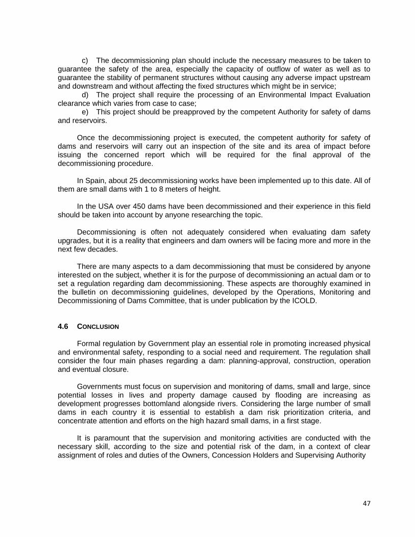
During the works Decommissioning completed
Fig. 4.3 – The currency Abion dam on the River. Source: Hydrographic Confederation Duero, Spain [10]
In Spain, just to mention an example, the procedure to be observed regarding a dam or
reservoir decommissioning, can be outlined in following main points:
a) Official documentary proceedings shall be filed; b) Draft of a decommissioning plan regarding the dam and its reservoir, defining all
the required refurbishment works to be executed on site and its surroundings, as well as its area of impact;
47
c) The decommissioning plan should include the necessary measures to be taken to guarantee the safety of the area, especially the capacity of outflow of water as well as to guarantee the stability of permanent structures without causing any adverse impact upstream and downstream and without affecting the fixed structures which might be in service;
d) The project shall require the processing of an Environmental Impact Evaluation clearance which varies from case to case;
e) This project should be preapproved by the competent Authority for safety of dams and reservoirs.
Once the decommissioning project is executed, the competent authority for safety of
dams and reservoirs will carry out an inspection of the site and its area of impact before issuing the concerned report which will be required for the final approval of the decommissioning procedure.
In Spain, about 25 decommissioning works have been implemented up to this date. All of
them are small dams with 1 to 8 meters of height. In the USA over 450 dams have been decommissioned and their experience in this field
should be taken into account by anyone researching the topic. Decommissioning is often not adequately considered when evaluating dam safety
upgrades, but it is a reality that engineers and dam owners will be facing more and more in the next few decades.
There are many aspects to a dam decommissioning that must be considered by anyone
interested on the subject, whether it is for the purpose of decommissioning an actual dam or to set a regulation regarding dam decommissioning. These aspects are thoroughly examined in the bulletin on decommissioning guidelines, developed by the Operations, Monitoring and Decommissioning of Dams Committee, that is under publication by the ICOLD.
4.6 CONCLUSION
Formal regulation by Government play an essential role in promoting increased physical and environmental safety, responding to a social need and requirement. The regulation shall consider the four main phases regarding a dam: planning-approval, construction, operation and eventual closure.
Governments must focus on supervision and monitoring of dams, small and large, since
potential losses in lives and property damage caused by flooding are increasing as development progresses bottomland alongside rivers. Considering the large number of small dams in each country it is essential to establish a dam risk prioritization criteria, and concentrate attention and efforts on the high hazard small dams, in a first stage.
It is paramount that the supervision and monitoring activities are conducted with the
necessary skill, according to the size and potential risk of the dam, in a context of clear assignment of roles and duties of the Owners, Concession Holders and Supervising Authority

48
4.7 REFERENCES [1] ABADJIEV,C.B. (2009)- “Small Dams Legislation”, Personal contribution received from
Bulgaria; [2] POLACEK, J. (2008) – Personal Contribution received from Czech Republic; [3] WORLD BANK GOOD PRACTICES NOTES (2008) - “Safety of Small/Rural Dams and
Barrier Lake Management”, July 2008 [4] CRUCHON P., DEGOUTTE G., LE DELLIOU P., MONIÉ N., ROYET P. (2009) – “New
regulations on the safety of dams and levees in France”, ICOLD-CIGB XXXII Congress, Brasilia, May 2009
[5] ASDSO – “Dam ownership – Responsibility and Liability”, Association of State Dam
Safety Officials, USA [6] USCOLD (1970) – “Model Law for State Supervision of Safety of Dams and Reservoirs”,
United States Committee on Large Dams, USA, 1970 [7] USSD – “Committee on Dam Decommissioning”, United States Society on Dams, USA,
August 2001. [8] OLDHAM K. (2009) – “Decommissioning Dams – Costs and Trends”, Water Power
Magazine, February 2009. [9] DeHeer, Lee (2001) – “Bridging the Gap: Meeting the World's Water and Environmental
Resources Challenges 2001”, American Society of Civil Engineers, USA, June 2001. [10] Restauración de Ríos – “Guía metodológica para la elaboración de proyectos”.
Ministerio de Medio Ambiente, Spain, 2007. [11] Water Act No 254/2001 (renewed at 2010), Czech Republic, § 61 and 62 concerning of
Dam Safety.
[12] Notice No 471/2001 (renewed at 2010), Czech Republic, concern to Dam Surveillance
and Supervision and Classification.

49
5. FEATURES OF THE DESIGN OF SMALL EMBANKMENT DAMS
5.1 INTRODUCTION
As many ICOLD bulletins have been drafted for large dams, the application to small
dams is documented in this bulletin. As 85% to 95% of the small dams built in the different countries are earthfill dams, this item the design of earthfill and rockfill dams are presented, trying to point out the best practice to be used in the different countries. More recently, with the boom of construction of small water power stations, small dams are usually been built for power generation.
The prime purpose of these dams is storage, mainly for irrigation or water supply. A
common multipurpose project involving small dams combines storage, flood control and recreational uses.
Design criteria and typical features for small dams are generally different from those of
high dams, because the construction methods focus upon economy. So the risks may increase and corresponding accidents may cause significant victims. Little attention is given to downstream hazard from floods caused by the failure of small dams; yet this is frequently the major the case during the severe rainy season.
It is important to emphasize that for new dams, no high risk can be accepted for
economical reasons. The knowledge is available to build safe dams. Criteria for Design: The basic principle of design is to produce a satisfactory functional
structure at a minimum total cost. Consideration must be given to maintenance requirements so that economies achieved in the initial cost of construction will not result in excessive maintenance costs. For minimum cost the dam must be designed for maximum utilization of the most economical materials available, including materials which must be excavated for its foundation and for appurtenant structures.
An earthfill dam must be safe and stable during all phases of construction and operation
of the reservoir. To accomplish this, the following criteria must be met: The embankment must be safe against overtopping during occurrence of the inflow
design flood by the provision of sufficient spillway and outlet capacity; The slopes of the embankment must be stable during construction and all conditions
of operation, including rapid drawdown of the reservoir; Seepage flow through the embankment foundation and abutment must be controlled,
so that no internal erosion takes place and so there is no sloughing in the area where the seepage emerges. The amount of water lost through seepage must be controlled so that is does not interfere with planned project functions;
The embankment must be safe against overtopping by wave action;
50
The upstream slope must be protected against erosion by wave action, and crest and the downstream slope must be protected against erosion due to wind, rain and cattle.
Summary of Wrong Practices Followed for Small Dams
Summary of wrong practices, too often used, are summarized below:
Foundations not investigated or investigated to a limited standard;
Hydrology study not done. Furthermore for smaller catchment areas less data is
available and empirical methods are usually used;
Freeboard not determined;
No camber provided;
Soil not appropriately compacted;
Seepage control not designed to standard;
Wrong material sometime used (e.g. dispersive clays);
Wrong equipment used during construction;
Erodible by-wash spillways, cutback erosion of spillway;
No slope protection;
No adequate features around outlet pipes;
Part time (and not full time) construction monitoring to confirm quality;
No routine inspections of the dam during its life;
No monitoring instruments installed;
Adoption of lower cost with higher risk.
Summary of Good Practices to be Followed for Small Dams
Summary of the best practices normally used are summarized below:
Investigation of foundations (to a minimum depth of 4-5m or the height of the dam)
and excavation of the organic and others inappropriate soils at the dam foundation;
Hydrology study, using at minimum empirical methods;
Choose cohesive materials for embankment, which are more stable during
overtopping;
Use appropriate and durable material for slope protection;
Adopt a standard design for filters and drains;
Use appropriate equipment for construction (especially for compaction) and monitor
construction quality;
Embed outlet pipes into concrete;
Access to outlet works necessary during floods and for maintenance;
Cattle not allowed on dam slopes and abutments;
Pipes are not allowed through or over embankments as they may cause piping
through removal of fines or pipe bursts.
Install some monitoring instruments and perform routine inspections during dam
operation.

51
5.2 DESIGN FLOODS Inadequate flood handling capacity not meeting design standards is normally caused by underestimating the design flood, not acknowledging the effect of the upstream approach channel on the hydraulic gradient or not ensuring that the dam was constructed with its total freeboard over the entire crest length of the dam. The hydraulic control must be correctly defined for the design flow by determining the hydraulic flow and energy lines based on the correct sectional information. In rural areas, in which usually is very seldom inhabitants downstream, it is applicable the design floods indicated in Table 5.1, like in South Africa.
Table 5.1 – Suggested Minimum Design Floods
Potential Hazard Classification - PHC
PHC = 1 PHC = 2
Recommended design flood 1:20 year 1:100 year
Safety evaluation check flood 1:50 year
1:200 year
The following are important regarding Table 5.1:
No overtopping to occur for this flood and freeboard remaining for protection against
wave run-up
Overflowing is acceptable, but very limited in duration and depth, and risk of
catastrophic failure must be very low.
Floods to be reduced when upstream control is applicable.
Flood attenuation in the reservoir above full supply level studies will determine the
discharge flood.
The owner may adopt a lower risk as indicated and in any case when the incremental
cost for upgrading to a higher standard is low.
In more populated areas and countries like France, for instance, the draft Guidelines for the design of dams spillways contains the following recommendations for small embankment dams.
Table 5.2 – Suggested Minimum Design Floods in France (April, 2011)
Potential Hazard Classification –
PHC PHC = 1 PHC = 2
Recommended Design Flood 1:300 year 1:1000 year
Safety Evaluation Check Flood 1:1000 year
1:10000 year
It is possible to see that the safety considerations could differ from one country to another, depending to the attitude of the society in regards to acceptable risk and on the level of economic development. But is always important to increase the requirements related to the dam safety, in order to reduce the risk and avoid any possible dam overtopping during severe storms. Most of the small dams are embankment dams, and this type of structure not accepts overtopping without the risk of failure.
52
During the life of the dam the potential hazard due to developments in the dam break flooding area can change. Upgrading to a higher Potential Hazard Classification (PHC) class is then necessary.
5.3 HOMOGENOUS AND ZONED EMBANKMENTS DESIGN
Essentially, designing an earthfill dam embankment primarily involves determining the
cross section that, when constructed with the available material, will fulfill its required function with adequate safety at minimum cost.
Where considerations is given to the possible loss of life, to the possibility of costly
property damage, and to the waste of money incidental to the failure of a dam, ample justification is provided for conservative procedures. For small dams, where the cost of explorations and laboratory testing of the embankment material for analytical studies together with the cost of the engineering constitutes an inordinate proportion of the total cost of the structure, the practice of designing on the basis of successful structures and past experience becomes even more appropriate.
In China, for instance, as can be seen in publication [1], the dam slopes are to be
determined mainly based on the nature of the foundation, the strength of soil material, the dry density, the dam height and the downstream drainage condition. But for small dams (H<15 m) stability analyses are not required, and reference may then be made to the available data from existing dams, as can be seen in Appendix I.
Considerable progress has been made in investigations and studies directed toward the
development of methods that will offer a comprehensive analysis of embankment stability. Present practice in determining the required cross section of an earth dam consists largely of designing to the slopes and characteristics of existing successful dams, making analytical and experimental studies for unusual conditions, and controlling closely the selection and placement of embankment materials.
Although the above practice may be criticized as being overly cautious and extravagant,
no better method has been conclusively demonstrated. Where considerations is given to the possible loss of life, to the possibility of costly properly damage, and to the waste of money incidental to the failure of a constructed dam, ample justification is provided for conservative procedures, as pointed out by the Bureau of Reclamation, 1987(3rd Edition).
Most small dams (85% to 95%) involves the construction of embankment dams as a
consequence of a method that is simple, straightforward and suitable for those sites where there is sufficient and properly material. Protection from seepage and slipping is provided by flattening the slopes, that is from a 2:1 to 3:1 gradient (H:V), and providing a thick covering of topsoil to carry any seepage to the toe of the dam.
5.3.1 Homogeneous Type
Embankment materials vary widely from place to place, particularly in respect to
gradation and permeability. If the difference in permeability between the impervious core and the downstream batter is great, no internal drainage is required. If the variation of the permeability between the inner core and the outer zones is not sufficient, then the embankment will become saturated after prolonged storage at full supply. Consequently, the
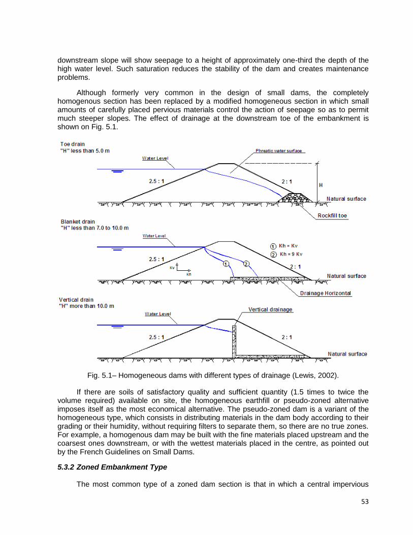
53
downstream slope will show seepage to a height of approximately one-third the depth of the high water level. Such saturation reduces the stability of the dam and creates maintenance problems.
Although formerly very common in the design of small dams, the completely homogenous section has been replaced by a modified homogeneous section in which small amounts of carefully placed pervious materials control the action of seepage so as to permit much steeper slopes. The effect of drainage at the downstream toe of the embankment is shown on Fig. 5.1.
Fig. 5.1– Homogeneous dams with different types of drainage (Lewis, 2002).
If there are soils of satisfactory quality and sufficient quantity (1.5 times to twice the volume required) available on site, the homogeneous earthfill or pseudo-zoned alternative imposes itself as the most economical alternative. The pseudo-zoned dam is a variant of the homogeneous type, which consists in distributing materials in the dam body according to their grading or their humidity, without requiring filters to separate them, so there are no true zones. For example, a homogenous dam may be built with the fine materials placed upstream and the coarsest ones downstream, or with the wettest materials placed in the centre, as pointed out by the French Guidelines on Small Dams.
5.3.2 Zoned Embankment Type The most common type of a zoned dam section is that in which a central impervious

54
core is flanked by zones of materials considered more pervious, called shells. These pervious zones or shells enclose, support and protect the impervious core, the upstream pervious zone affords stability against rapid drawdown; and the downstream pervious zone acts as a drain to control seepage and lower the phreatic surface. In many cases, a filter between the impervious zone and downstream shell and a drainage layer beneath the downstream are necessary. In Table 5.4 are presented some examples of zoned and homogeneous small dams in Japan, illustrating their typical sections and also some rehabilitation measures under way in order to improve their safety conditions.
5.4 FREEBOARD
5.4.1 Definitions of Freeboard Freeboard is the vertical distance between the crest of the dam and a specified still-
water reservoir water surface elevation. Common definitions of freeboard are as follows: Normal freeboard – vertical distance from dam crest elevation to normal operating
reservoir still-water surface elevation. Minimum freeboard – vertical distance from dam crest elevation to maximum reservoir
still-water surface elevation during inflow design flood with spillway operating 5.4.2 Freeboard Design Considerations
Freeboard must be sufficient to prevent overtopping of the dam that could result from
reasonable combinations of a number of factors, as illustrated on Figure 5.2: Wind-generated wave action, wind setup, and wave runup; Earthquake and/or landslide-generated waves and runup; Post-construction settlement of embankment dams and foundations; Provision for malfunction of spillways (especially gated structures) and outlet works,
and Site-specific uncertainties including flood hydrology.
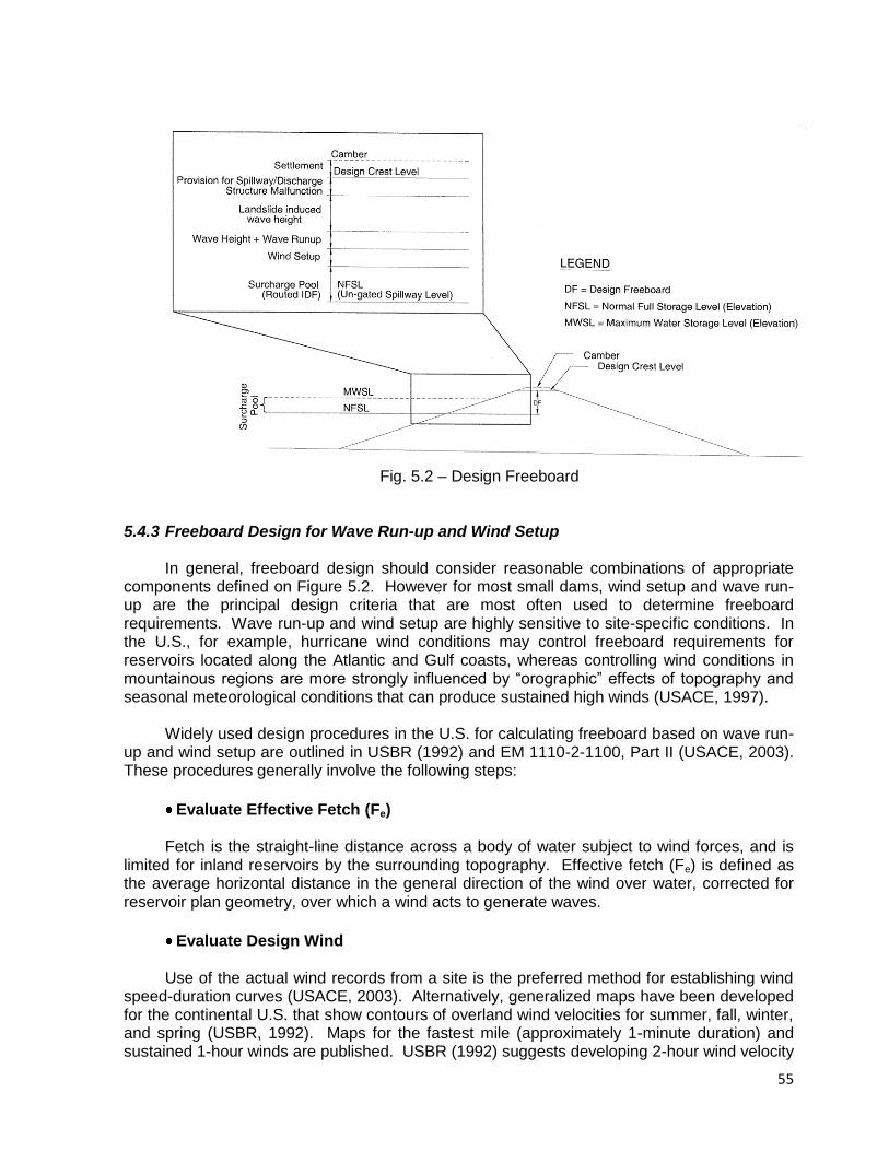
55
Fig. 5.2 – Design Freeboard
5.4.3 Freeboard Design for Wave Run-up and Wind Setup In general, freeboard design should consider reasonable combinations of appropriate
components defined on Figure 5.2. However for most small dams, wind setup and wave run-up are the principal design criteria that are most often used to determine freeboard requirements. Wave run-up and wind setup are highly sensitive to site-specific conditions. In the U.S., for example, hurricane wind conditions may control freeboard requirements for reservoirs located along the Atlantic and Gulf coasts, whereas controlling wind conditions in mountainous regions are more strongly influenced by “orographic” effects of topography and seasonal meteorological conditions that can produce sustained high winds (USACE, 1997).
Widely used design procedures in the U.S. for calculating freeboard based on wave run-
up and wind setup are outlined in USBR (1992) and EM 1110-2-1100, Part II (USACE, 2003). These procedures generally involve the following steps:
Evaluate Effective Fetch (Fe) Fetch is the straight-line distance across a body of water subject to wind forces, and is
limited for inland reservoirs by the surrounding topography. Effective fetch (Fe) is defined as the average horizontal distance in the general direction of the wind over water, corrected for reservoir plan geometry, over which a wind acts to generate waves.
Evaluate Design Wind Use of the actual wind records from a site is the preferred method for establishing wind
speed-duration curves (USACE, 2003). Alternatively, generalized maps have been developed for the continental U.S. that show contours of overland wind velocities for summer, fall, winter, and spring (USBR, 1992). Maps for the fastest mile (approximately 1-minute duration) and sustained 1-hour winds are published. USBR (1992) suggests developing 2-hour wind velocity
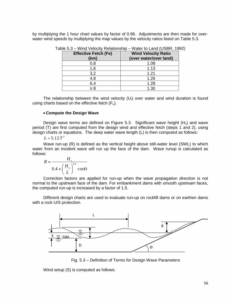
56
by multiplying the 1 hour chart values by factor of 0.96. Adjustments are then made for over-water wind speeds by multiplying the map values by the velocity ratios listed on Table 5.3.
Table 5.3 – Wind Velocity Relationship – Water to Land (USBR, 1992)
Effective Fetch (Fe) (km)
Wind Velocity Ratio (over water/over land)
0,8 1.08
1,6 1.13
3,2 1.21
4,8 1.26
6,4 1.28
≥ 8 1.30
The relationship between the wind velocity (Uf) over water and wind duration is found
using charts based on the effective fetch (Fe).
Compute the Design Wave Design wave terms are defined on Figure 5.3. Significant wave height (Hs) and wave
period (T) are first computed from the design wind and effective fetch (steps 1 and 2), using design charts or equations. The deep water wave length (L) is then computed as follows:
212.5 TL
Wave run-up (R) is defined as the vertical height above still-water level (SWL) to which water from an incident wave will run up the face of the dam. Wave runup is calculated as follows:
cot4.0
5.0
L
H
HR
s
s
Correction factors are applied for run-up when the wave propagation direction is not normal to the upstream face of the dam. For embankment dams with smooth upstream faces, the computed run-up is increased by a factor of 1.5.
Different design charts are used to evaluate run-up on rockfill dams or on earthen dams
with a rock U/S protection.
Fig. 5.3 – Definition of Terms for Design Wave Parameters
Wind setup (S) is computed as follows:
R
L
SWL S
D Ѳ
57
D
FUS
ef
1400
2
Where Uf is the design wind velocity over water, and D = average water depth along the fetch.
The freeboard requirement for wind-generated waves is the sum of the wave run-up (R)
and wind setup (S). Freeboard is generally based on maximum probable wind conditions when the reference elevation is the normal operating level. When estimating the freeboard to be used with the probable maximum reservoir level, a lesser wind condition is used because it is improbable that maximum wind conditions will occur simultaneously with the maximum flood level (USACE, 1997). 5.4.4 First Approximations for Freeboard Requirements
As a first estimate, the U.S. Bureau of Reclamation (USBR, 1992) uses the empirical
guidelines summarized on Table 5.3 for preliminary studies of small dams. The values shown on Table 5.3 were based on wind velocities of 160 km/hour (100 miles/hour) for estimating normal freeboard and 80 km/hour (50 miles/hour) for minimum freeboard.
Table 5.4 – Freeboard Requirements for Preliminary Studies of Small Dams for rock faced
slope (USBR, 1987, 1992)
Longest fetch (km)
Normal Freeboard (m)
Freeboard – MFL(*) (m)
< 1.6 1.2 0.9
1.6 1.5 1.2
4.0 1.8 1.5
8.0 2.4 1.8
16.0 3.0 2.1
(*) MFL = Maximum flood level.
A large number of dams have failed due to overtopping and consequently greater attention must be paid to this feature. Freeboard should not be less than 1,0 m, even for small dams, as pointed out by Lewis (2002).[4]
In the French Guidelines for Small Dams, 2006, it is recommended that the minimum
freeboard for fill (providing a safety margin from maximum water level, settlement and
upstream cracking of the crest) depending on the parameter VH2 , in which the minimum
values are presented in Table 5.5. Of course, if calculations using more detailed formula give a higher value for freeboard, that higher value should be used. In such a case a less rigid wave wall (e.g. gabions) can provide protection between minimum freeboard (Table 4) and calculated freeboard.
Table 5.5 – Minimum freeboard for fill dams according to parameter VH2
VH2 5 30 100 200
Rmin (m) 0,40 0,60 0,80 0,70
According to practice in Czech Republic, and considering that the breakwater at some small dams with large reservoir and long run-up of water waves can be considered.
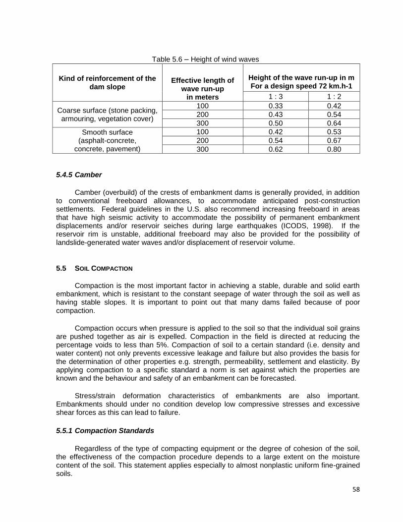
58
Table 5.6 – Height of wind waves
5.4.5 Camber
Camber (overbuild) of the crests of embankment dams is generally provided, in addition
to conventional freeboard allowances, to accommodate anticipated post-construction settlements. Federal guidelines in the U.S. also recommend increasing freeboard in areas that have high seismic activity to accommodate the possibility of permanent embankment displacements and/or reservoir seiches during large earthquakes (ICODS, 1998). If the reservoir rim is unstable, additional freeboard may also be provided for the possibility of landslide-generated water waves and/or displacement of reservoir volume.
5.5 SOIL COMPACTION
Compaction is the most important factor in achieving a stable, durable and solid earth
embankment, which is resistant to the constant seepage of water through the soil as well as having stable slopes. It is important to point out that many dams failed because of poor compaction.
Compaction occurs when pressure is applied to the soil so that the individual soil grains are pushed together as air is expelled. Compaction in the field is directed at reducing the percentage voids to less than 5%. Compaction of soil to a certain standard (i.e. density and water content) not only prevents excessive leakage and failure but also provides the basis for the determination of other properties e.g. strength, permeability, settlement and elasticity. By applying compaction to a specific standard a norm is set against which the properties are known and the behaviour and safety of an embankment can be forecasted.
Stress/strain deformation characteristics of embankments are also important. Embankments should under no condition develop low compressive stresses and excessive shear forces as this can lead to failure.
5.5.1 Compaction Standards
Regardless of the type of compacting equipment or the degree of cohesion of the soil, the effectiveness of the compaction procedure depends to a large extent on the moisture content of the soil. This statement applies especially to almost nonplastic uniform fine-grained soils.
Kind of reinforcement of the dam slope
Effective length of wave run-up
in meters
Height of the wave run-up in m For a design speed 72 km.h-1
1 : 3 1 : 2
Coarse surface (stone packing, armouring, vegetation cover)
100 0.33 0.42
200 0.43 0.54
300 0.50 0.64
Smooth surface (asphalt-concrete,
concrete, pavement)
100 0.42 0.53
200 0.54 0.67
300 0.62 0.80
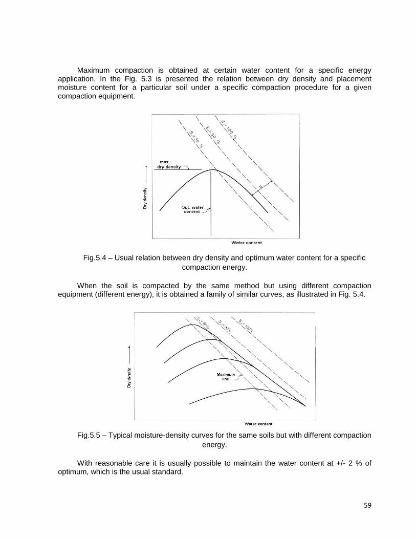
59
Maximum compaction is obtained at certain water content for a specific energy application. In the Fig. 5.3 is presented the relation between dry density and placement moisture content for a particular soil under a specific compaction procedure for a given compaction equipment.
Fig.5.4 – Usual relation between dry density and optimum water content for a specific
compaction energy.
When the soil is compacted by the same method but using different compaction equipment (different energy), it is obtained a family of similar curves, as illustrated in Fig. 5.4.
Fig.5.5 – Typical moisture-density curves for the same soils but with different compaction
energy.
With reasonable care it is usually possible to maintain the water content at +/- 2 % of optimum, which is the usual standard.

60
If the moisture content of the soil in the field is greater than the optimum, the soil should be given an opportunity to dry out in storage after spreading.
If it is less, water should be added in the borrow pit or by sprinkling before compaction.
The addition of water can be undertaken by:
Mixing water into the soil by cultivation with a disc plough or rotary hoe;
Irrigating as the soil is spread out on the embankment;
Deep ripping and irrigating the soil before excavation, also known as “borrow pit
irrigation”.
Borrow pit irrigation is usually more economical than adding water directly to the construction surface. It results in more even distribution of water, and saves time by avoiding the necessity to water the construction surface between each layer.
The water content at which a soil is compacted has an effect on all the physical
properties of the compacted soil, including the permeability. Experience indicates that an increase in initial water content from a value somewhat below the optimum to a value somewhat above is likely to cause a large decrease in the coefficient of permeability. 5.5.2 Water Content Variation and Effect on Geomechanical Properties
For the core of an embankment, sealing and therefore elasticity and cohesion are
dominant and strength is second in line. For the outer zones of an embankment, stability and therefore strength is most important and elasticity not a priority.
The above provides the motivation for specification of water variation 0% to 2% of
optimum for core impervious materials and –1% to +2% or +3% for semi-pervious materials. The strength and elasticity values obtained in the laboratory at the specified density and
optimum moisture content of a material can be taken as design parameters if water content and density control were done during construction in accordance with the mentioned criteria. 5.5.3 Layer Thicknesses
Layer thicknesses are to be tested with the placement and construction machines to be
used during construction. Special care for proper mixing with water and effective compaction through the complete layer must be investigated. Test sections must also be constructed, opened and checked visually.
If layer thickness cannot be determined experimentally then layer thicknesses must be
limited to 20 cm after compaction, depending on the material. Maximum thickness after compaction must always be limited to 30 cm. 5.5.4 Quality Control During Compaction
This is very important. The frequency of testing per layer and per volume placed must be
specified. A test section is normally specified with more frequent testing by Troxler and sand replacement methods. Troxler machines must be calibrated. When soil materials in borrow areas change a new Standard Proctor maximum dry density and optimum water content

61
characteristic must be determined. This must be used as standard to compare the characteristics of the placed and compacted materials.
When during compaction a layer dries out before the next layer is placed the layer must
be reworked and recompacted at the correct water content after watering and mixing. Badly compacted layers can cause high seepage rates and possible piping failures. 5.5.5 Compaction in Confined Areas
In areas inaccessible to large compaction machines compaction by smaller machines in
thinner layers have to be performed. If necessary compaction by hand can be used but then at 2% of optimum water content to ensure proper wetting of all soil particles. Quality assurance here is of most importance as many failures of earthfill dams occurred due to piping along say the bottom outlet pipe caused by below standard compaction (Oosthuizen 1985).
Figure 5.6 shows a pipe with intact seepage collars, with the photograph taken after an internal erosion failure of a small dam. The fact that anti-seep collars have not prevented many failures implies that most of the crack features causing the failure occurred in the earthfill outside the collars, probably as a consequence of the poor compaction of the soil between the collars.
In some cases internal erosion occurred through hydraulic fractures in surrounding
embankment soils that were dispersive clays, but not along the conduit as is often presumed.
Fig. 5.6 – Pipe with intact anti-seepage collars shortly after failure of a small dam
(McCook/2004). Seepage and piping along outlet pipes are a major cause of failure of small dams. As
pipes become larger in diameter it becomes more difficult to compact the soil properly, down the sides of the pipe. A good precaution consists in placing draining or filtering granular material on either side of the pipe over its downstream third, in order to block or drainage strips in the fill.
5.5.6 Testing of The Pipe

62
After the pipe is in place, and before any backfilling, it should be tested for leakage applying pressure through the use of compressed air. The weak point will be at the joints. Testing should be carried out at a pressure of 150 % of the maximum working pressure, as used in Australia (Lewis, 2002). No leakage is permitted over a two-hour test period. Where pipes that are prone to damage are used, such as rubber ring-jointed PVC pipes, a further test is recommended after 1.0 meter of soil cover has been emplaced. Failure at this time can be corrected at a much lower cost than after completion of the embankment.
The French Guidelines for small dams recommend to do a water tightness test before
embedding in concrete by plugging the two ends of the pipe and raising pressure up to twice the reservoir depth plus 0.2 MPa, and then maintaining this pressure for 8 hours.
5.5.7 Compaction of Filters
Recent practice regarding compaction of filter materials is in the line of not to compact filters in excess, for the following reasons:
filter material must collapse during differential movement of the adjacent earthfill
materials
grading of filter materials change during compaction and after compaction filter criteria
or permeability requirements may not be met (Sherard, 1984).
If filters are compacted it is recommended that its strength, crushing strength and grading are tested during construction with the specific machine.
5.6 DAM FOUNDATION TREATMENT
The dam foundation must always be stripped to a depth of at least 0.50 meter to remove
topsoil, organic material, trees, roots, grass, etc.
The mechanical characteristics of loose materials in the foundation (alluvium, colluvium, eluvium) are often sufficient to support a fill dam about 10 to 15 meters high. In regions where predominate warm weather most part of the year, the presence of organic soils at the river bed is very frequent, and in such cases it is recommended to remove such layers completely, as a consequence of there low shear strength and high compressibility.
Organic material in the form of partly decomposed vegetation is the primary constituent of peat soils. Varying amounts of finely divided vegetation are found in plastic and nonplastic sediments and often affect their properties. Organic soils are dark gray or black and usually have a characteristic odor of decay. The tendency for soils high in organic content to create voids as a result of decay or to change the physical characteristics of a soil mass through chemical alteration makes them undesirable for engineering use.
Settlement of a loose foundation due to the weight of the fill dam is evaluated by compressibility tests. After construction, it should generally not exceed 5% of the total thickness of the compressible layers.
Watertightening and drainage systems must be installed to achieve an acceptable leakage flow and avoid any risk of piping (internal erosion) and uplift on the downstream side. A filter may have to be placed at the fill dam/ foundation, at the downstream axis position in order to assure better internal drainage conditions to the earthfill.
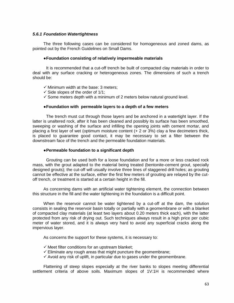
63
5.6.1 Foundation Watertightness The three following cases can be considered for homogeneous and zoned dams, as
pointed out by the French Guidelines on Small Dams. ● Foundation consisting of relatively impermeable materials It is recommended that a cut-off trench be built of compacted clay materials in order to
deal with any surface cracking or heterogeneous zones. The dimensions of such a trench should be:
Minimum width at the base: 3 meters; Side slopes of the order of 1/1; Some meters depth with a minimum of 2 meters below natural ground level. ● Foundation with permeable layers to a depth of a few meters The trench must cut through those layers and be anchored in a watertight layer. If the
latter is unaltered rock, after it has been cleaned and possibly its surface has been smoothed, sweeping or washing of the surface and infilling the opening joints with cement mortar, and placing a first layer of wet (optimum moisture content (+ 2 or 3%) clay a few decimeters thick, is placed to guarantee good contact, it may be necessary to set a filter between the downstream face of the trench and the permeable foundation materials.
● Permeable foundation to a significant depth Grouting can be used both for a loose foundation and for a more or less cracked rock
mass, with the grout adapted to the material being treated (bentonite-cement grout, specially designed grouts); the cut-off will usually involve three lines of staggered drill holes; as grouting cannot be effective at the surface, either the first few meters of grouting are relayed by the cut-off trench, or treatment is started at a certain height in the fill.
As concerning dams with an artificial water tightening element, the connection between
this structure in the fill and the water tightening in the foundation is a difficult point. When the reservoir cannot be water tightened by a cut-off at the dam, the solution
consists in sealing the reservoir basin totally or partially with a geomembrane or with a blanket of compacted clay materials (at least two layers about 0.20 meters thick each), with the latter protected from any risk of drying out. Such techniques always result in a high price per cubic meter of water stored, and it is always very hard to avoid any superficial cracks along the impervious layer.
As concerns the support for these systems, it is necessary to: Meet filter conditions for an upstream blanket; Eliminate any rough areas that might puncture the geomembrane; Avoid any risk of uplift, in particular due to gases under the geomembrane. Flattening of steep slopes especially at the river banks to slopes meeting differential
settlement criteria of above soils. Maximum slopes of 1V:1H is recommended where
64
specialised techniques are not applied. All corners, holes and unevenness have to be filled with concrete to provide a surface on which positive compaction can be supplied.
Rough surfaces on which positive compaction of earthfill is not possible, are to be
smoothed by blooming a cement mortar.
5.6.2 Foundation Drainage For drainage of flows from the foundation, the most satisfactory solution consists in
placing a drainage blanket at the base of the downstream shoulder, at the fill-foundation contact, leading to the vertical or slopped drain in the central part of the fill.
This drainage blanket, which may be compartmented in order to determine the behavior
of each different zone, should be placed for any large structure (H² v >700). For smaller dams
(H² v <700), where geological conditions permit, the drainage blanket may be reduced by
placement of draining strips (in particular in the areas judged to be the most vulnerable in the river banks). The thickness of the layers must be sufficient to discharge the foreseen flow with a minimum thickness for each horizontal granular layer of 0.20 meters (drain and filter). When using only sand the minimum layer thickness need to be 0.50 meters for practical purposes.
If there is a relatively impermeable surface layer in the foundation, covering a much more permeable layer with its upper surface at a depth of less than H/3, it is recommended that relief well (in general with piezometers) be drilled at the downstream toe of the dam, spaced 10 to 25 meters apart. The relief well must be protected with a filtering material from the surrounding relatively impermeable material.
Drainage of the foundation for very small dams where H² v <20 provided that the foundation
is sufficiently watertight.
Special attention must be paid to the placement of the first earthfill layer. In case of compaction of earthfill against earthfill the top layer of in-situ soil must also be ploughed and mixed with the first imported layer. In case of compaction of the first earthfill layer on a rock foundation use of a sheepfoot roller is to be prevented so that the foundation surface is not damaged. In confined areas hand compaction in thin layers 0 – 3% above optimum water content must be specified (slush grouting).
The contact below the core cut-off must be treated with special care. An area 3m
upstream of the core as well as the sides of the core must be treated, rock surfaces especially with concrete to enhance good compaction. The contact below the outer zones can be treated at a lesser degree. Rough areas and holes for example can be treated with earthfill instead of concrete.
Slopes in the foundation are not to be provided too steep because e.g. where the
elasticity modules of clay is less arch action can develop with associated low stresses. With high hydraulic gradients water can burst and a leak can develop. Finite element techniques can be used to determine the correct slope.
5.7 DRAINAGE SYSTEM FOR EARTHFILL DAMS A drainage system for a homogeneous fill dam consists of two parts (see Figure 5.7):
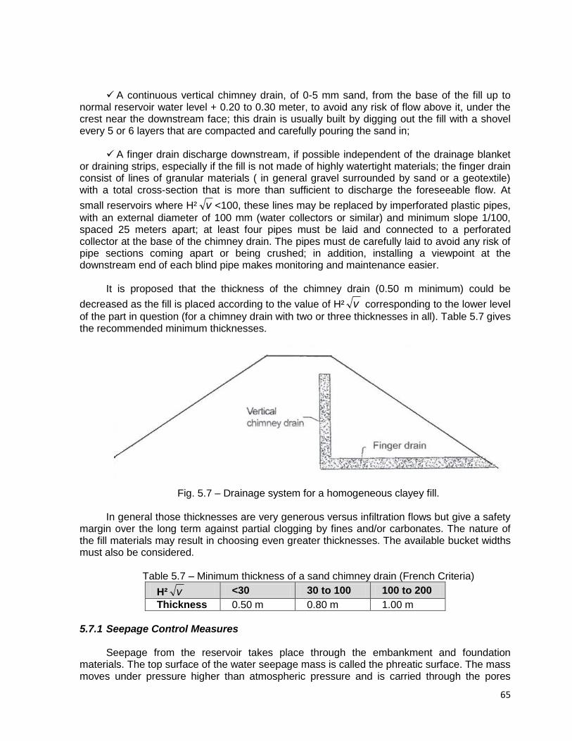
65
A continuous vertical chimney drain, of 0-5 mm sand, from the base of the fill up to
normal reservoir water level + 0.20 to 0.30 meter, to avoid any risk of flow above it, under the crest near the downstream face; this drain is usually built by digging out the fill with a shovel every 5 or 6 layers that are compacted and carefully pouring the sand in;
A finger drain discharge downstream, if possible independent of the drainage blanket
or draining strips, especially if the fill is not made of highly watertight materials; the finger drain consist of lines of granular materials ( in general gravel surrounded by sand or a geotextile) with a total cross-section that is more than sufficient to discharge the foreseeable flow. At
small reservoirs where H² v <100, these lines may be replaced by imperforated plastic pipes,
with an external diameter of 100 mm (water collectors or similar) and minimum slope 1/100, spaced 25 meters apart; at least four pipes must be laid and connected to a perforated collector at the base of the chimney drain. The pipes must de carefully laid to avoid any risk of pipe sections coming apart or being crushed; in addition, installing a viewpoint at the downstream end of each blind pipe makes monitoring and maintenance easier.
It is proposed that the thickness of the chimney drain (0.50 m minimum) could be
decreased as the fill is placed according to the value of H² v corresponding to the lower level
of the part in question (for a chimney drain with two or three thicknesses in all). Table 5.7 gives the recommended minimum thicknesses.
Fig. 5.7 – Drainage system for a homogeneous clayey fill.
In general those thicknesses are very generous versus infiltration flows but give a safety
margin over the long term against partial clogging by fines and/or carbonates. The nature of the fill materials may result in choosing even greater thicknesses. The available bucket widths must also be considered.
Table 5.7 – Minimum thickness of a sand chimney drain (French Criteria)
H² v <30 30 to 100 100 to 200
Thickness 0.50 m 0.80 m 1.00 m
5.7.1 Seepage Control Measures
Seepage from the reservoir takes place through the embankment and foundation
materials. The top surface of the water seepage mass is called the phreatic surface. The mass moves under pressure higher than atmospheric pressure and is carried through the pores
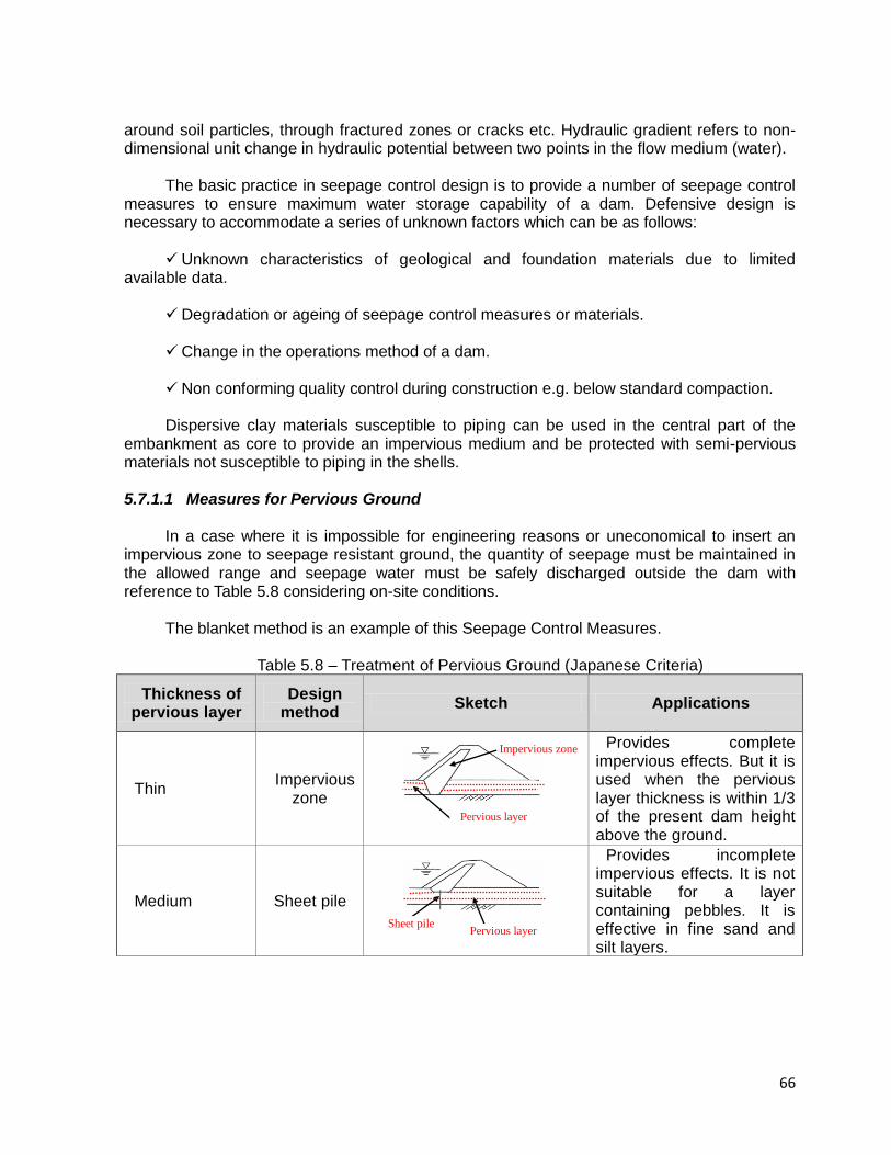
66
around soil particles, through fractured zones or cracks etc. Hydraulic gradient refers to non-dimensional unit change in hydraulic potential between two points in the flow medium (water).
The basic practice in seepage control design is to provide a number of seepage control measures to ensure maximum water storage capability of a dam. Defensive design is necessary to accommodate a series of unknown factors which can be as follows:
Unknown characteristics of geological and foundation materials due to limited
available data. Degradation or ageing of seepage control measures or materials. Change in the operations method of a dam. Non conforming quality control during construction e.g. below standard compaction. Dispersive clay materials susceptible to piping can be used in the central part of the
embankment as core to provide an impervious medium and be protected with semi-pervious materials not susceptible to piping in the shells.
5.7.1.1 Measures for Pervious Ground
In a case where it is impossible for engineering reasons or uneconomical to insert an
impervious zone to seepage resistant ground, the quantity of seepage must be maintained in the allowed range and seepage water must be safely discharged outside the dam with reference to Table 5.8 considering on-site conditions.
The blanket method is an example of this Seepage Control Measures.
Table 5.8 – Treatment of Pervious Ground (Japanese Criteria)
Thickness of pervious layer
Design method
Sketch Applications
Thin Impervious
zone
Provides complete impervious effects. But it is used when the pervious layer thickness is within 1/3 of the present dam height above the ground.
Medium Sheet pile
Provides incomplete impervious effects. It is not suitable for a layer containing pebbles. It is effective in fine sand and silt layers.
Impervious zone
Impervious zone
Pervious layer
Sheet pile
Sheet pile Pervious layer
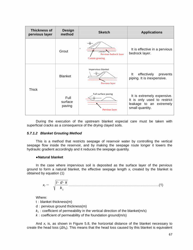
67
Thickness of pervious layer
Design method
Sketch Applications
Grout
It is effective in a pervious bedrock layer.
Thick
Blanket
It effectively prevents piping. It is inexpensive.
Full surface paving
It is extremely expensive. It is only used to restrict leakage to an extremely small quantity.
During the execution of the upstream blanket especial care must be taken with
superficial cracks as a consequence of the drying clayed soils.
5.7.1.2 Blanket Grouting Method This is a method that restricts seepage of reservoir water by controlling the vertical
seepage flow inside the reservoir, and by making the seepage route longer it lowers the hydraulic gradient accordingly and it reduces the seepage quantity.
● Natural blanket In the case where impervious soil is deposited as the surface layer of the pervious
ground to form a natural blanket, the effective seepage length xr created by the blanket is obtained by equation (1)
xr = 1
k
kdt ・・……………………………………………………………………(1)
Where:
t:blanket thickness(m)
d:pervious ground thickness(m)
k1:coefficient of permeability in the vertical direction of the blanket(m/s)
k:coefficient of permeability of the foundation ground(m/s)
And xr is, as shown in Figure 5.8, the horizontal distance of the blanket necessary to
create the head loss (Δhb). This means that the head loss caused by this blanket is equivalent
Curtain grouting
Bedrock→
Curtain grouting
Pervious bedrock layer
Impervious blanket
Pervious layer
Full surface paving
Pervious layer
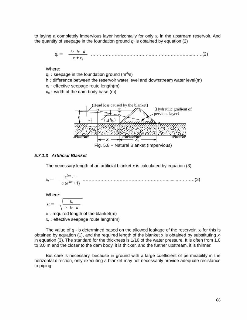
68
to laying a completely impervious layer horizontally for only xr in the upstream reservoir. And the quantity of seepage in the foundation ground qf is obtained by equation (2)
qf = dr xx
dhk
+
・・ ………………………………….………………………..…….(2)
Where:
qf:seepage in the foundation ground (m3/s)
h:difference between the reservoir water level and downstream water level(m)
xr:effective seepage route length(m)
xd:width of the dam body base (m)
(Head loss caused by the blanket) (Hydraulic gradient of pervious layer)
xr xd
h
t
d
(Δhb )
Fig. 5.8 – Natural Blanket (Impervious)
5.7.1.3 Artificial Blanket
The necessary length of an artificial blanket x is calculated by equation (3)
xr = )( 1+
1-2
2
ax
ax
ea
e…………………………………………………........…………(3)
Where:
a = dkt
k
・・
1
x:required length of the blanket(m)
xr:effective seepage route length(m)
The value of q f is determined based on the allowed leakage of the reservoir, xr for this is
obtained by equation (1), and the required length of the blanket x is obtained by substituting xr in equation (3). The standard for the thickness is 1/10 of the water pressure. It is often from 1.0 to 3.0 m and the closer to the dam body, it is thicker, and the further upstream, it is thinner.
But care is necessary, because in ground with a large coefficient of permeability in the
horizontal direction, only executing a blanket may not necessarily provide adequate resistance to piping.
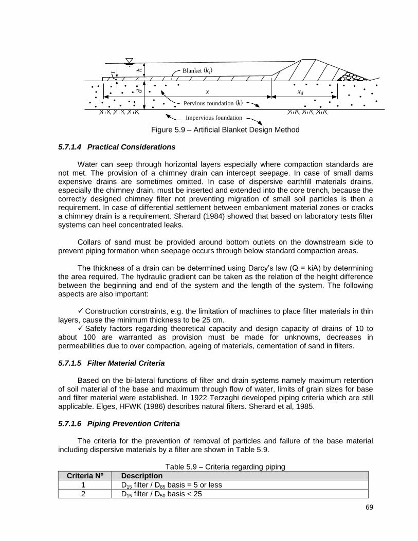
69
Blanket (k1)
Pervious foundation (k )
Impervious foundation
x xd d
t h
Figure 5.9 – Artificial Blanket Design Method
5.7.1.4 Practical Considerations
Water can seep through horizontal layers especially where compaction standards are
not met. The provision of a chimney drain can intercept seepage. In case of small dams expensive drains are sometimes omitted. In case of dispersive earthfill materials drains, especially the chimney drain, must be inserted and extended into the core trench, because the correctly designed chimney filter not preventing migration of small soil particles is then a requirement. In case of differential settlement between embankment material zones or cracks a chimney drain is a requirement. Sherard (1984) showed that based on laboratory tests filter systems can heel concentrated leaks.
Collars of sand must be provided around bottom outlets on the downstream side to
prevent piping formation when seepage occurs through below standard compaction areas. The thickness of a drain can be determined using Darcy’s law (Q = kiA) by determining
the area required. The hydraulic gradient can be taken as the relation of the height difference between the beginning and end of the system and the length of the system. The following aspects are also important:
Construction constraints, e.g. the limitation of machines to place filter materials in thin
layers, cause the minimum thickness to be 25 cm. Safety factors regarding theoretical capacity and design capacity of drains of 10 to
about 100 are warranted as provision must be made for unknowns, decreases in permeabilities due to over compaction, ageing of materials, cementation of sand in filters.
5.7.1.5 Filter Material Criteria
Based on the bi-lateral functions of filter and drain systems namely maximum retention
of soil material of the base and maximum through flow of water, limits of grain sizes for base and filter material were established. In 1922 Terzaghi developed piping criteria which are still applicable. Elges, HFWK (1986) describes natural filters. Sherard et al, 1985.
5.7.1.6 Piping Prevention Criteria
The criteria for the prevention of removal of particles and failure of the base material
including dispersive materials by a filter are shown in Table 5.9.
Table 5.9 – Criteria regarding piping
Criteria Nº Description
1 D15 filter / D85 basis = 5 or less
2 D15 filter / D50 basis < 25

70
3 D15 / D85 < 5 for sandy silt and clay (D85 of 0,1 to 0,5)
4 D15<0,5 for fine clay (D85 from 0,3 to 0,1)
5 D15<0,3 for fine silts with low cohesion and plasticity (LL<30 (D85 from 0,3 to 0,1)
6 D15 < 0,2 for fine soil (D85 of 0,02)
5.7.1.7 Criteria Regarding Permeability
Criteria ensuring sufficient flow in the filter/drain are shown in Table 5.10.
Table 5.10 – Criteria for drains
Criteria number Details
1 5 < D15 filter / D15 base < 40
2 The grain size associated with the 0,075 sieve size based on the
washed grading of sand must be less than 5%
Note: Laboratory studies showed that the permeability of filter sand significantly (in
portions of 100) decreases with the fines more than 5% through the 0,075 sieve size. The washed grading test must be used to remove the fine fraction (Cedergren, 1977).
5.7.1.8 Uniform Criteria
Depending on the uniform characteristics of the materials the limits for criteria number 1
in Table 5.8 must be used as those shown in Table 5.11.
Table 5.11 – Filter uniformity criteria
Characteristic Lower limit Higher limit
Uniform: D60/D10 = 3 to 4 5 40
Non-uniform: rounded grains 12 40
Non-uniform: sharp edge grains 6 18
5.7.1.9 Criteria for the Inherent Stability of a Filter
The Stability Relation defined as D15 (coarse) / D85 (fine) applied to 5% intervals on the
particle grain size distribution must always be smaller than 5. Sherard showed in 1984 that the coefficient of uniformity Cu = D60 / D10 should satisfy the following conditions:
Table 5.12 – Criteria for inherent stability of a filter layer
Cu-value Guidelines
10 Inherent instability possible
10 < Cu < 20 Inherent stability only possible in soils with grading curves with
sharp changes in bends
20 < Cu < 75
The soil will be stable when the grading curve is smooth without sharp changes in directions or significant flat zones.
5.7.1.10 Cohesion Clay Criteria
71
It is generally accepted that cohesive non-dispersive clays are stable in some cases where above-mentioned criteria are not satisfied. The standard is not well defined. The explanation by the Corps of Engineers in 1955 is mostly accepted.
“The above criteria will be used when protecting all soils except for medium to highly plastic clays without sand or silt partings, which by the above (basic) criteria may be required multi-stage filters. For these clay soils, the D15 size of the filters may be as great as 0,4mm and the above D50 (supplementary) criteria will be disregarded (This refers to the D50 (filter)/D50(base) < 25 rule). This relaxation in criteria for protecting medium to highly plastic clays will allow the use of one-stage filter material; however the filter must be well graded, and to ensure non-segregation of the filter, a coefficient of uniformity (ration of D60 to D10) of not greater than 20 will be required”.
5.7.1.11 Criteria Regarding Dispersive Clay
First criterion is that the filter material must not be dispersive. Criteria stipulated in Table
5.8 are to be followed. Second practice to obtain less permeability is to compact to at least 98% of the Standard Proctor density at 0% to 2% above optimum. The paper by Melvill (1986) describes further aspects regarding filtration of dispersive soils.
5.7.1.12 Organic Material Criteria
Less than 2% organic materials in filters are acceptable.
5.7.1.13 Criteria and Practice Regarding Synthetic Materials Woven, needle punched polyester synthetic materials are available in South Africa, since
1972. Synthetic materials are to be compared to natural materials regarding filter criteria. The exact size and void ratios, however, can only be determined accurately using experimental data.
It is generally assumed that synthetic materials have an application. The following is
important regarding the application to dams: Stresses in embankment caused by differential settlement can cause the material to
be torn apart which influences the permeability and stability against piping. Synthetic materials can therefore be used where permeability is not a priority e.g.
downstream side of sand of a chimney filter. Access to synthetic materials must be possible. Therefore use as chimney filter
material is not acceptable as access is not possible. It must be remembered that the material can clog.
Construction problems are to be acknowledged. Synthetic materials can be damaged
under vehicle loads. When one hole develop, water and soil can move through with no control regarding filter material. Ultra-violet rays of the sun can cause deterioration and exposure must be prevented.
5.8 SLOPE STABILITY
72
5.8.1 Introduction
To prevent failures that can develop through the slopes of embankment dams the slopes
must be flattened to acceptable grades which provide acceptable safety factors, based on the characteristics of the soil from which it is built.
Stability analysis of a fill dam concerns the determination of the forces exerted on the
dam and analysis of combinations of those forces; of those combinations, the worst case scenarios are considered in terms of the envisaged failure mechanism. 5.8.2 Critical Cases for Analysis
During construction and life of an earthfill embankment structure the following cases may
occur: During construction temporary slopes must always be stable. Furthermore, the outer
slopes must also be stable during development of hydrostatic pore pressures. During full reservoir conditions and developed seepage conditions the stability of the
downstream shell is critical. Sufficient drainage systems will improve the stability. In case of sudden draw down of water in the reservoir the upstream slope can fail
under saturated earthfill conditions. Dynamic forces can also develop and must be considered in seismic zones.
5.8.3 Limiting Equilibrium Methods The two dimensional equilibrium methods are based on the following: An embankment cross section is evaluated. The earthfill above the slip failure is divided into blocks. Each block is analysed for weight and shear resistance and the final safety factor
determined. For all methods except for the wedge method vertical blocks are selected. For the wedge
method a series of levels are selected and is applicable to the following: where a horizontal earth layer with lower shear resistance (e.g. clay with high
plasticity) is situated in the foundation. where the foundation consists of rock, the core consists of material with small grains
and the outer zones consist of material with rough grains.
Methods Various methods as follows were developed in years indicated:
73
Simple Bishop (1955) Spencer (1967) Janbu (1957)
Morgestern and Price (1965)
Determination of most critical slope surface The following approach must be followed to select the most critical surface: Determine a series of safety factors with various radii but same centre point and plot
on scale. Redo above with different centre points encroaching to the lowest safety factor. Plot of
safety factors contours to be made. More than one critical surface must be identified for e.g. rockfill dams where surface
slopes are occurring.
Selection of shear parameter The selection of shear parameter to be tested meeting site conditions is normally based
on specific test methods. A summary and explanation are given in Table 5.13.
Table 5.13 – Summary of Triaxial Tests
Test method Application in stability analysis Remark
UU (Undrained,
Unconsolidated)
Test represents end of construction condition for core zones. Also applicable to impervious foundations where consolidation is slow in comparison with rate of earthfill placement.
At low test pressure cavitation occur during shear. Stress curves may have curves if materials are saturated.
CU (Consolidated,
Undrained)
Test represents behaviour of impervious or semi-pervious materials of embankments or foundations which consolidated during construction and which were exposed to stress change during sudden draw down conditions. Test also used to analyse stationary conditions in downstream slope.
Undrained stress increases with decreasing moisture content and increases in consolidation stresses.
CD (Consolidated,
Drained)
Test applicable to impervious and semi-pervious soils with hydrostatic pore pressures, before or after shear, under slow increase in load is revealed. Also used to evaluate shear values under setting out conditions where excess hydrostatic pressure during the life of the dam is determined.
CU strength is higher in value than CD strength for expansion soils.
5.8.4 Minimum Safety Factors Against Slip Circle Failures
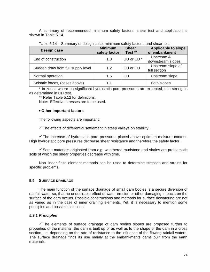
74
A summary of recommended minimum safety factors, shear test and application is shown in Table 5.14.
Table 5.14 – Summary of design case, minimum safety factors, and shear test
Design case Minimum
safety factor Shear Test **
Applicable to slope of embankment
End of construction 1,3 UU or CD * Upstream &
downstream slopes
Sudden draw from full supply level 1,2 CU or CD Upstream slope of
full section
Normal operation 1,5 CD Upstream slope
Seismic forces, (cases above) 1,1 Both slopes
* In zones where no significant hydrostatic pore pressures are excepted, use strengths as determined in CD test.
** Refer Table 5.12 for definitions. Note: Effective stresses are to be used.
Other important factors The following aspects are important: The effects of differential settlement in steep valleys on stability. The increase of hydrostatic pore pressures placed above optimum moisture content.
High hydrostatic pore pressures decrease shear resistance and therefore the safety factor. Some materials originated from e.g. weathered mudstone and shales are problematic
soils of which the shear properties decrease with time. Non linear finite element methods can be used to determine stresses and strains for
specific problems.
5.9 SURFACE DRAINAGE
The main function of the surface drainage of small dam bodies is a secure diversion of rainfall water so, that no undesirable effect of water erosion or other damaging impacts on the surface of the dam occurs. Possible constructions and methods for surface dewatering are not as varied as in the case of inner draining elements. Yet, it is necessary to mention some principles and possible solutions. 5.9.1 Principles
The elements of surface drainage of dam bodies slopes are proposed further to
properties of the material, the dam is built up of as well as to the shape of the dam in a cross section, i.e. depending on the rate of resistance to the influence of the flowing rainfall waters. The surface drainage finds its use mainly at the embankments dams built from the earth materials.
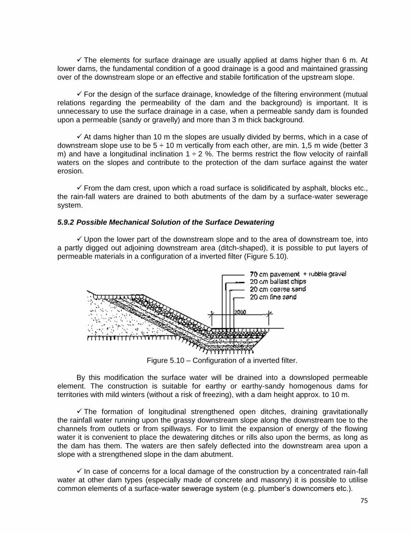
75
The elements for surface drainage are usually applied at dams higher than 6 m. At lower dams, the fundamental condition of a good drainage is a good and maintained grassing over of the downstream slope or an effective and stabile fortification of the upstream slope.
For the design of the surface drainage, knowledge of the filtering environment (mutual
relations regarding the permeability of the dam and the background) is important. It is unnecessary to use the surface drainage in a case, when a permeable sandy dam is founded upon a permeable (sandy or gravelly) and more than 3 m thick background.
At dams higher than 10 m the slopes are usually divided by berms, which in a case of
downstream slope use to be 5 ÷ 10 m vertically from each other, are min. 1,5 m wide (better 3 m) and have a longitudinal inclination 1 ÷ 2 %. The berms restrict the flow velocity of rainfall waters on the slopes and contribute to the protection of the dam surface against the water erosion.
From the dam crest, upon which a road surface is solidificated by asphalt, blocks etc.,
the rain-fall waters are drained to both abutments of the dam by a surface-water sewerage system.
5.9.2 Possible Mechanical Solution of the Surface Dewatering
Upon the lower part of the downstream slope and to the area of downstream toe, into
a partly digged out adjoining downstream area (ditch-shaped), it is possible to put layers of permeable materials in a configuration of a inverted filter (Figure 5.10).
Figure 5.10 – Configuration of a inverted filter.
By this modification the surface water will be drained into a downsloped permeable
element. The construction is suitable for earthy or earthy-sandy homogenous dams for territories with mild winters (without a risk of freezing), with a dam height approx. to 10 m.
The formation of longitudinal strengthened open ditches, draining gravitationally
the rainfall water running upon the grassy downstream slope along the downstream toe to the channels from outlets or from spillways. For to limit the expansion of energy of the flowing water it is convenient to place the dewatering ditches or rills also upon the berms, as long as the dam has them. The waters are then safely deflected into the downstream area upon a slope with a strengthened slope in the dam abutment.
In case of concerns for a local damage of the construction by a concentrated rain-fall
water at other dam types (especially made of concrete and masonry) it is possible to utilise common elements of a surface-water sewerage system (e.g. plumber’s downcomers etc.).
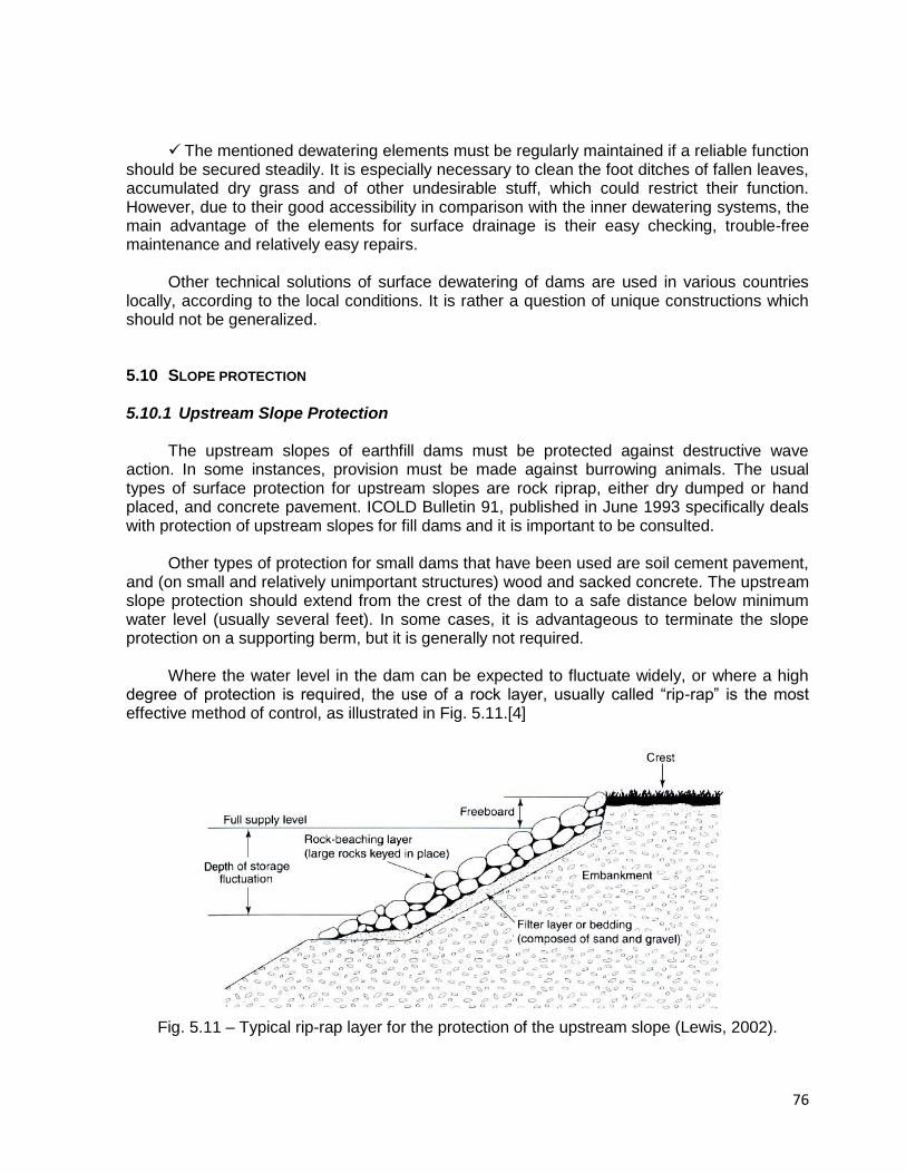
76
The mentioned dewatering elements must be regularly maintained if a reliable function
should be secured steadily. It is especially necessary to clean the foot ditches of fallen leaves, accumulated dry grass and of other undesirable stuff, which could restrict their function. However, due to their good accessibility in comparison with the inner dewatering systems, the main advantage of the elements for surface drainage is their easy checking, trouble-free maintenance and relatively easy repairs.
Other technical solutions of surface dewatering of dams are used in various countries
locally, according to the local conditions. It is rather a question of unique constructions which should not be generalized.
5.10 SLOPE PROTECTION
5.10.1 Upstream Slope Protection The upstream slopes of earthfill dams must be protected against destructive wave
action. In some instances, provision must be made against burrowing animals. The usual types of surface protection for upstream slopes are rock riprap, either dry dumped or hand placed, and concrete pavement. ICOLD Bulletin 91, published in June 1993 specifically deals with protection of upstream slopes for fill dams and it is important to be consulted.
Other types of protection for small dams that have been used are soil cement pavement,
and (on small and relatively unimportant structures) wood and sacked concrete. The upstream slope protection should extend from the crest of the dam to a safe distance below minimum water level (usually several feet). In some cases, it is advantageous to terminate the slope protection on a supporting berm, but it is generally not required.
Where the water level in the dam can be expected to fluctuate widely, or where a high
degree of protection is required, the use of a rock layer, usually called “rip-rap” is the most effective method of control, as illustrated in Fig. 5.11.[4]
Fig. 5.11 – Typical rip-rap layer for the protection of the upstream slope (Lewis, 2002).

77
The supporting layer for the rip-rap is intended to protect the fill from the hydrodynamic effects of waves and from erosion. The U.S. Corps of Engineers recommends the following rockfill diameter (D50) and thickness of rip-par layer presented at the following table [3].
Table 5.15 – Rip-Rap layer recommended by U.S. Corps of Engineers.
Wave height (m)
Average rockfill diameter – D50 (m)
Layer thickness (m)
0 – 0.60 0.25 0.30
0.60 – 1.20 0.30 0.46
1.20 – 1.80 0.38 0.61
1.80 – 2.40 0.46 0.76
2.40 – 3.00 0.53 0.91
The same corporation recommends the following filter layer or bedding thickness
between the rip-rap and the earthfill.
Table 5.16 – Transition thickness layer recommend by U.S. Corps of Engineers
Maximum wave height (m) Bedding thickness layer (m)
0 – 1.20 0.15
1.20 – 2.40 0.25
2.40 – 3.00 0.30
For wave height from 0.30 to 1.55 m it is also possible to use the following table, present
by the French Guidelines [5].
Table 5.17 – Dimensions of upstream rip-rap (French Guidelines on Small Dams)
Wave height (m)
Thickness - e (m)
Block diameter – D50 (m)
0.30 0.30 0.20
0.55 0.40 0.25
0.80 0.50 0.30
1.05 0.60 0.40
1.30 0.70 0.45
1.55 0.80 0.50
The supporting layer may be replaced by a puncture-resistant geotextile in cases in
which the fill material is fairly resistant to erosion.
5.10.2 Selecting the Type of Upstream Protection Experience has shown that in most cases, dumped riprap furnishes the best upstream
slope protection at the lowest ultimate cost. Approximately 100 dams, located in various sections of the United States with a wide variety of climate conditions and wave severity, were examined by the Corps of Engineers. The results of this survey were used as a basis for establishing the most practical and economical means for slope protection. The dams were from 5 to 50 years old and were constructed by various agencies. This survey found that:
Dumped riprap failed in only 5 percent of the cases it was used; and failures were due
to improper size of stones.
78
Hand-placed riprap failed in 30 percent of the cases it was used; failures were due to
the usual method of single-course construction.
Concrete pavement failed in 36 percent of the cases it was used; failures were generally due to inherent deficiencies with this type of construction.
This survey substantiated the premise that dumped riprap is by far the most preferable
type of upstream slope protection. Figure 5.12 presents the riprap at the upstream slope of Paraitinga dam, in Brazil, which is a very well dam built for water supply using a good gneiss as rock material.
Fig. 5.12 – Upstream gneiss rip-rap at the Paraitinga dam, in Brazil.
The superiority of dumped rock riprap for upstream slope protection and its low cost of
maintenance compared with other types of slope protection have been demonstrated so convincingly that it has been considered economical to transport rock considerable distances for major dams.
At a small dam, the surface area of the reservoir is often very small when the reservoir is
almost empty. Furthermore, the period in which the reservoir is at a low level generally lasts only a few weeks (e.g. at dams built for irrigation purposes at the end of the summer). In such cases, it may be possible to provide no protection for the lower part of the upstream slope. In this case, a berm should be installed at the base of the protected top part. That berm will serve as a support for the protective layer and will extend horizontally outward for at least one meter past that layer. The berm elevation should be at least 2 h (h = wave height) below normal reservoir water level.
Of course, partial protection of the upstream slope can be envisaged using the same
technique for dams with little variation in water level, such as lakes for recreational purposes, diversion dams, etc. In this case, protection by plant cover may be considered if wave height is less than 0.50 meter.
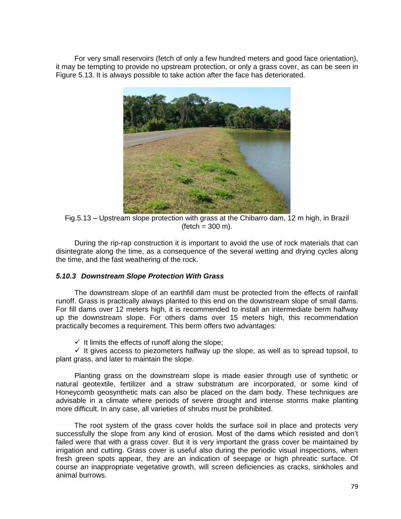
79
For very small reservoirs (fetch of only a few hundred meters and good face orientation), it may be tempting to provide no upstream protection, or only a grass cover, as can be seen in Figure 5.13. It is always possible to take action after the face has deteriorated.
Fig.5.13 – Upstream slope protection with grass at the Chibarro dam, 12 m high, in Brazil
(fetch = 300 m). During the rip-rap construction it is important to avoid the use of rock materials that can
disintegrate along the time, as a consequence of the several wetting and drying cycles along the time, and the fast weathering of the rock.
5.10.3 Downstream Slope Protection With Grass
The downstream slope of an earthfill dam must be protected from the effects of rainfall
runoff. Grass is practically always planted to this end on the downstream slope of small dams. For fill dams over 12 meters high, it is recommended to install an intermediate berm halfway up the downstream slope. For others dams over 15 meters high, this recommendation practically becomes a requirement. This berm offers two advantages:
It limits the effects of runoff along the slope; It gives access to piezometers halfway up the slope, as well as to spread topsoil, to
plant grass, and later to maintain the slope. Planting grass on the downstream slope is made easier through use of synthetic or
natural geotextile, fertilizer and a straw substratum are incorporated, or some kind of Honeycomb geosynthetic mats can also be placed on the dam body. These techniques are advisable in a climate where periods of severe drought and intense storms make planting more difficult. In any case, all varieties of shrubs must be prohibited.
The root system of the grass cover holds the surface soil in place and protects very
successfully the slope from any kind of erosion. Most of the dams which resisted and don’t failed were that with a grass cover. But it is very important the grass cover be maintained by irrigation and cutting. Grass cover is useful also during the periodic visual inspections, when fresh green spots appear, they are an indication of seepage or high phreatic surface. Of course an inappropriate vegetative growth, will screen deficiencies as cracks, sinkholes and animal burrows.
80
The grass cover must be maintained by irrigation and cutting. Irrigation by sprinklers is
necessary to prevent withering of the grass. For this reason grass cover is not fitted in arid regions. Grass cover is useful also during the periodic visual inspections; when fresh green spots appear, they are an indication of seepage or high phreatic surface.
The grass must be cut from time to time to prevent high and inappropriate vegetative growth, which will screen deficiencies as cracks, sinkholes and animal burrows. Excessive vegetation can obscure large area of the slope and prevent good visual inspection. Problems that threaten the dam integrity can develop and remain undetected if they are obscured by high vegetation. Excessive vegetation can provide habitat for rodent and burrowing animals, which burrows are a threat to the embankment dam by causing piping.
Although grass cover is desirable as slope protection, growth of deep rooted large shrubs and trees is undesirable. Their deep root system could shorten the seepage path, providing seepage pats and initiate piping, especially on the decaying root system when vegetation dies.
5.10.4 Downstream Slope Protection With Gravel
The riprap slope protection is made up of at least two layers: The outer layer consists of broken rock or boulders which prevent erosion. The inner layer is the filter or bedding and could consist of one or two layers. If it is
one layer it consists of a sand-gravel mixture. If it is of two layers, the inner layer is of coarse sand and the outer is of gravel. The relation between the coarseness of the grains of two adjacent layers must be the filter rules in order to prevent the removing of material from the underlying inner layer through the pores of the outer material. If these rules are not regarded, the surface runoff can erode the under layer, undermine the rockfill layer, damage all the surface protection and form gullies in the protected embankment.
The slope upon which the riprap is placed must be flat to prevent rockfill from moving
down the slope. Hand-placed rockfill, providing usually good protection, is a thin blanket. Most modern rockfill is dumped in place, resulting in a thicker blanket of protection. Vegetation on the riprap must be weeded out, because it could move and replace the stones and damage the protection.
A berm on the mid height of the slope will stop the flowing down rain water and decrease
its velocity. It will also increase the slope stability. A ditch on the interface of the berm with the slope to collect the flowing down water is very useful. The berm will also support the upper slope protection. 5.10.5 Protection From Seepage Piping
The downstream slope protection of embankment dams serves to protect the slope not
only from surface erosion, but also from erosion due to inner seepage from the dam. For this reason it is advisable the filter under the rockfill and the concrete protection to have the possibility to avoid erosion from any uncontrolled seepage.
81
The junction of the downstream slope with the ground surface is protected from seepage and piping with a downstream toe. It is a small rockfill zone, divided from the main dam by one or two filter layers and acting as drain. Except of horizontal blanket drain and chimney drain with blanket, the toe zone of rock material is a good internal drain to control seepage. Dams without internal drains have seepage problems, because the seepage (phreatic) surface emerges on the slope surface. The toe dam protects the dam also from tail water if any.
The part of the valley side against which the dam is built is the abutment. Surface runoff
from the abutment could cause rapid erosion on the slope-abutment interface. To avoid this there must be provided a concrete ditch to collect all rain surface water from the abutment and the dam slope.
Seepage is also often coming out on the lower part of the slope-abutment interface. This
contact is prone to seepage because the embankment fill near the abutment is less dense and less watertight. The embankment fill near the abutments is less dense because compaction is difficult along the interface. A toe drain is to be put on the slope-abutment interface to carry the internal seepage water away from the dam. It must be met by filter under the slope protection to avoid any seepage erosion. 5.11 CREST DESIGN
Placing a layer of gravel on the crest will in particular avoid the formation of ruts due to
traffic and desiccation of the last layers of compacted clay materials. If the crest is not protected, it can experience severe erosion. Crest erosion protection is usually the road surfacing such as gravel, concrete pavement or asphalt and depends on the amount of the anticipated traffic. If no traffic is expected, a grass cover could be enough. In designing the dam crest of a small earthfill dam the following items should be considered:
Width Drainage Camber Surfacing Safety requirements
5.11.1 Width The crest width of an earthfill dam depends on considerations such as nature of
embankment materials and minimum allowable percolation distance through the embankment at normal reservoir level, height and importance of structure, possible roadway requirements and allowable materials at the site.
Because of practical difficulties in determining these factors, the crest width is, as a rule,
determined empirically and largely by precedent experience. According to the Bureau of Reclamation, in the United States, the following formula is suggested for crest width for small earthfill dams:
w = z/5 + 10 where: w = width of crest in feet z = height of dam, in feet, above the streambed.
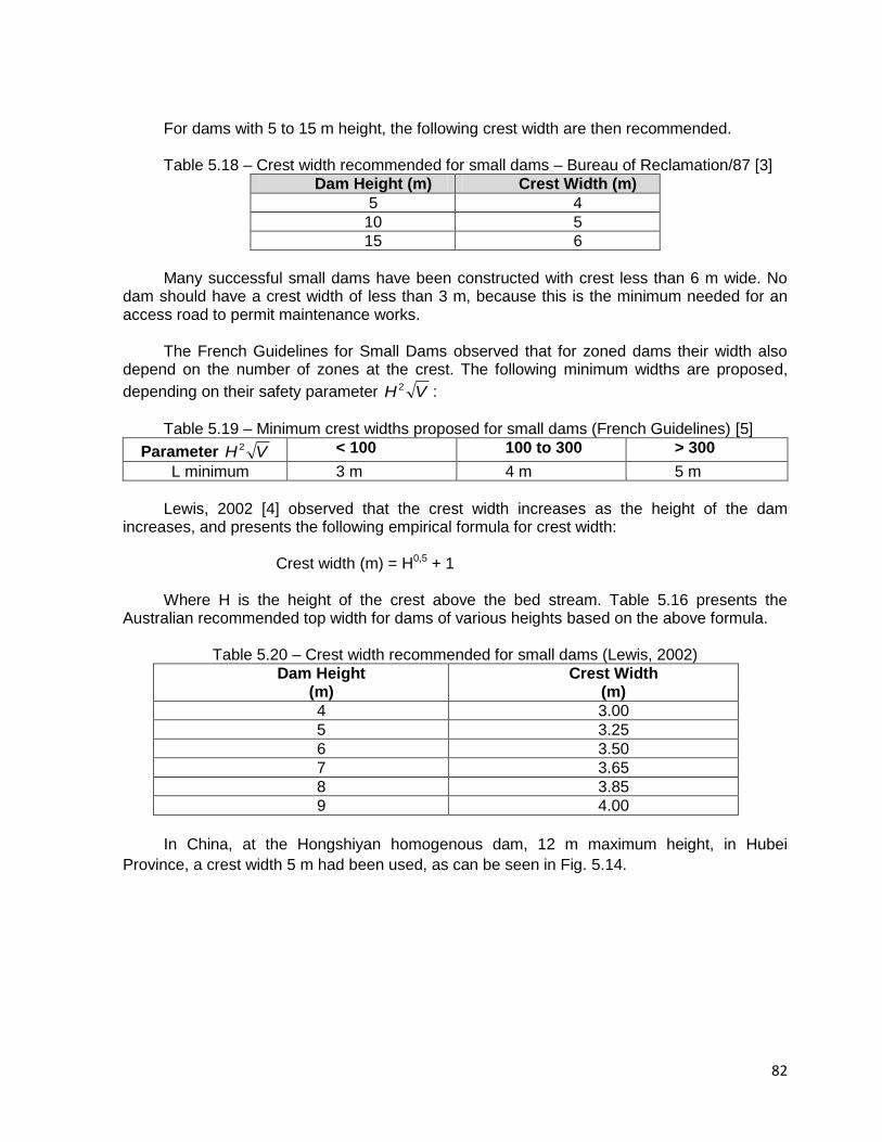
82
For dams with 5 to 15 m height, the following crest width are then recommended. Table 5.18 – Crest width recommended for small dams – Bureau of Reclamation/87 [3]
Dam Height (m) Crest Width (m)
5 4
10 5
15 6
Many successful small dams have been constructed with crest less than 6 m wide. No
dam should have a crest width of less than 3 m, because this is the minimum needed for an access road to permit maintenance works.
The French Guidelines for Small Dams observed that for zoned dams their width also
depend on the number of zones at the crest. The following minimum widths are proposed,
depending on their safety parameter VH2 :
Table 5.19 – Minimum crest widths proposed for small dams (French Guidelines) [5]
Parameter VH2 < 100 100 to 300 > 300
L minimum 3 m 4 m 5 m
Lewis, 2002 [4] observed that the crest width increases as the height of the dam
increases, and presents the following empirical formula for crest width: Crest width (m) = H0,5 + 1 Where H is the height of the crest above the bed stream. Table 5.16 presents the
Australian recommended top width for dams of various heights based on the above formula.
Table 5.20 – Crest width recommended for small dams (Lewis, 2002)
Dam Height (m)
Crest Width (m)
4 3.00
5 3.25
6 3.50
7 3.65
8 3.85
9 4.00
In China, at the Hongshiyan homogenous dam, 12 m maximum height, in Hubei
Province, a crest width 5 m had been used, as can be seen in Fig. 5.14.
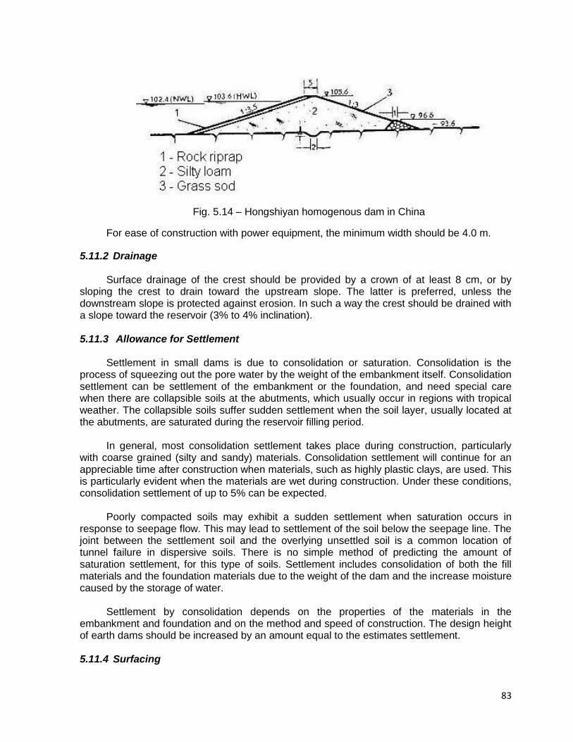
83
Fig. 5.14 – Hongshiyan homogenous dam in China
For ease of construction with power equipment, the minimum width should be 4.0 m.
5.11.2 Drainage Surface drainage of the crest should be provided by a crown of at least 8 cm, or by
sloping the crest to drain toward the upstream slope. The latter is preferred, unless the downstream slope is protected against erosion. In such a way the crest should be drained with a slope toward the reservoir (3% to 4% inclination).
5.11.3 Allowance for Settlement
Settlement in small dams is due to consolidation or saturation. Consolidation is the
process of squeezing out the pore water by the weight of the embankment itself. Consolidation settlement can be settlement of the embankment or the foundation, and need special care when there are collapsible soils at the abutments, which usually occur in regions with tropical weather. The collapsible soils suffer sudden settlement when the soil layer, usually located at the abutments, are saturated during the reservoir filling period.
In general, most consolidation settlement takes place during construction, particularly
with coarse grained (silty and sandy) materials. Consolidation settlement will continue for an appreciable time after construction when materials, such as highly plastic clays, are used. This is particularly evident when the materials are wet during construction. Under these conditions, consolidation settlement of up to 5% can be expected.
Poorly compacted soils may exhibit a sudden settlement when saturation occurs in
response to seepage flow. This may lead to settlement of the soil below the seepage line. The joint between the settlement soil and the overlying unsettled soil is a common location of tunnel failure in dispersive soils. There is no simple method of predicting the amount of saturation settlement, for this type of soils. Settlement includes consolidation of both the fill materials and the foundation materials due to the weight of the dam and the increase moisture caused by the storage of water.
Settlement by consolidation depends on the properties of the materials in the
embankment and foundation and on the method and speed of construction. The design height of earth dams should be increased by an amount equal to the estimates settlement.
5.11.4 Surfacing
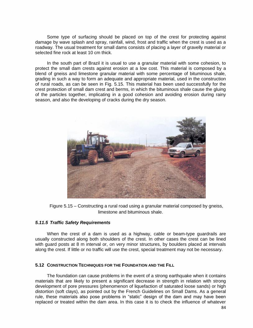
84
Some type of surfacing should be placed on top of the crest for protecting against damage by wave splash and spray, rainfall, wind, frost and traffic when the crest is used as a roadway. The usual treatment for small dams consists of placing a layer of gravelly material or selected fine rock at least 10 cm thick.
In the south part of Brazil it is usual to use a granular material with some cohesion, to
protect the small dam crests against erosion at a low cost. This material is composed by a blend of gneiss and limestone granular material with some percentage of bituminous shale, grading in such a way to form an adequate and appropriate material, used in the construction of rural roads, as can be seen in Fig. 5.15. This material has been used successfully for the crest protection of small dam crest and berms, in which the bituminous shale cause the gluing of the particles together, implicating in a good cohesion and avoiding erosion during rainy season, and also the developing of cracks during the dry season.
Figure 5.15 – Constructing a rural road using a granular material composed by gneiss,
limestone and bituminous shale.
5.11.5 Traffic Safety Requirements
When the crest of a dam is used as a highway, cable or beam-type guardrails are usually constructed along both shoulders of the crest. In other cases the crest can be lined with guard posts at 8 m interval or, on very minor structures, by boulders placed at intervals along the crest. If little or no traffic will use the crest, special treatment may not be necessary.
5.12 CONSTRUCTION TECHNIQUES FOR THE FOUNDATION AND THE FILL
The foundation can cause problems in the event of a strong earthquake when it contains
materials that are likely to present a significant decrease in strength in relation with strong development of pore pressures (phenomenon of liquefaction of saturated loose sands) or high distortion (soft clays), as pointed out by the French Guidelines on Small Dams. As a general rule, these materials also pose problems in “static” design of the dam and may have been replaced or treated within the dam area. In this case it is to check the influence of whatever

85
material has been left in place or has not been treated beyond the dam’s upstream and downstream toes. In the case of sandy layers, classic treatment consists in building a mesh of vertical drains (to drain overpressures generated by the earthquake) or in improving the ground by densifying it.
For the fill, modifications may be necessary to deal with any internal problems and
strains that may occur. Generally, a probable consequence of a strong earthquake is the appearance of concentrated leakage through the dam. Such modifications concern zoning of the fill, resistance of the materials to retrogressive erosion, and design of the crest. The following precautions are worth mentioning:
Avoid fine, cohesion less and uniform soil in saturated zones; Provide a chimney drain or enlarge it in the case of homogeneous fills; Design transition zones that are as wide as possible; Be specially prudent with the thickness of filters; Place a layer of sand upstream from the core to plug any cracks that may be caused
by an earthquake; Build the dam or its core with materials offering good resistance to internal erosion
(plastic clays, sandy gravel with fines of a very continuous grading). In addition, as recommended by the French Guidelines, if the design earthquake
intensity is very strong, it may be wise to increase freeboard and crest width.
5.13 REFERENCES
[1] CHINCOLD (1979) – Dam Construction by the Chinese People, The Chinese National
Committee on Large Dams;. [2] SHERARD, J.L., DUNNIGAN, L.P. (1985) – “Filters and Leakage Control in
Embankment Dams”, Proc. Symposium on Seepage and Leakage from Dams, ASCE. [3] Bureau of Reclamation (1987) – Design of Small Dams, United States Department of the
Interior, A Water Resources Technical Publication; [4] LEWIS, B. (2002) – Farm Dams – Planning, Construction and Maintenance, National
Library of Australia Cataloguing; [5] CEMAGREF (2002) – Small Dams – Guidelines for Design, Construction and
Monitoring, French Committee on Large Dams; [6] DURAND JM, ROYET P, MÉRIAUX P (2002) – Technique des Petits Barrages en
Afrique Sahélienne et Équatoriale, Cemagref Editions. [7] SMEC (2006) – Draft Guidelines for Managing Small Dams, SMEC Australia Pty Ltd,
Guide developed on behalf of The Republic of Uganda. [8] JSIDRE (2006) – The Guidelines for Designing of Agricultural Land Improvement
Projects, “Tameike Small Dams”, Japanese Society of Irrigation, Drainage and Reclamation Engineering, February 2006.

86
APPENDIX - RECOMMENDED EMBANKMENT SLOPES FOR EARTHFILL DAMS
1. Experience of China
In China the completed earth dams are mainly of rolled-fill type, and comprise up to date
over 95% of the entire large dams. There are many causes of slope failure. The major ones are the improper control of the placement water content, the low dry density and the low shearing strength.
Practice has shown that for a homogeneous dam of poor placement quality, sudden
drawdown of reservoir level from full height to one third of the full height may easily cause sliding of the upstream slope, and that the high position of phreatic line during the first filling of the reservoir or the saturation of the embankment by submergence after continual raining may also lead to sliding of the downstream slope. In some cases, the dam slopes during construction or reservoir drawdown often slid along the weak layers interbedded in the foundation.
In the Hubei Province, the dam slopes are specified within the limit as shown in Table
5.21. This method provides convenience for the masses and also ensures the dam safety. Table 5.21 – Range of embankment slopes for dams below 15 m.[1]
Ho
mo
gen
eo
s D
am
s Sand Clay Silty loam
Berm Upstream
slope (from top to bottom)
Downstream slope
(from top to bottom)
Berm Upstream slope (from top to bottom)
Downstream slope
(from top to bottom)
Width of
berms (m)
Nº of Berms
Width of berms (m)
Nº of Berms
1.5 1 1:2.5
1:2.75 1:2.25 1:2.5
1:2.25 1:2.5
1:2.0 1:2.25
Slo
pin
g-c
ore
Eart
h D
am
s
Embankment Sloping-core and cutoff trench
Berm Upstream
slope (from top to
bottom)
Downstream slope
(from top to bottom)
Top thickness (normal to dam slope)
Bottom thickness (normal to dam slope)
Bottom width of
foundation cutoff trench
Bottom width of
abutment cutoff trench
Width of
berms (m)
Nº of Berms
1.5 1 1:2.50 1:2.75
1:2.0 1:2.25
0.8 m ¼ of dam
height
¼ of dam height
¼ of dam height
Eart
h d
am
s w
ith
cen
tral
co
re
Dam Shell Central core and cutoff trench
Berm Upstream
slope (from top to
bottom)
Downstream slope
(from top to bottom)
Top width
Slope
Bottom width of
foundation cutoff trench
Bottom width of
abutment cutoff trench
Width of
berms (m)
Nº of Berms
1.5 1 1:2~1:2.25
1:2.25~1:2.50
1:1.75~1:2.0
1:2~1:2.25 1.5 1:0.2
¼ water head
½ water head
2. Experience of United States
•Homogeneous Dam
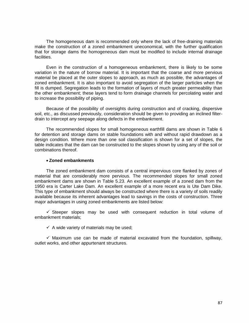
87
The homogeneous dam is recommended only where the lack of free-draining materials
make the construction of a zoned embankment uneconomical, with the further qualification that for storage dams the homogeneous dam must be modified to include internal drainage facilities.
Even in the construction of a homogeneous embankment, there is likely to be some
variation in the nature of borrow material. It is important that the coarse and more pervious material be placed at the outer slopes to approach, as much as possible, the advantages of zoned embankment. It is also important to avoid segregation of the larger particles when the fill is dumped. Segregation leads to the formation of layers of much greater permeability than the other embankment; these layers tend to form drainage channels for percolating water and to increase the possibility of piping.
Because of the possibility of oversights during construction and of cracking, dispersive
soil, etc., as discussed previously, consideration should be given to providing an inclined filter-drain to intercept any seepage along defects in the embankment.
The recommended slopes for small homogeneous earthfill dams are shown in Table 6
for detention and storage dams on stable foundations with and without rapid drawdown as a design condition. Where more than one soil classification is shown for a set of slopes, the table indicates that the dam can be constructed to the slopes shown by using any of the soil or combinations thereof.
Zoned embankments The zoned embankment dam consists of a central impervious core flanked by zones of
material that are considerably more pervious. The recommended slopes for small zoned embankment dams are shown in Table 5.23. An excellent example of a zoned dam from the 1950 era is Carter Lake Dam. An excellent example of a more recent era is Ute Dam Dike. This type of embankment should always be constructed where there is a variety of soils readily available because its inherent advantages lead to savings in the costs of construction. Three major advantages in using zoned embankments are listed below:
Steeper slopes may be used with consequent reduction in total volume of
embankment materials; A wide variety of materials may be used; Maximum use can be made of material excavated from the foundation, spillway,
outlet works, and other appurtenant structures.
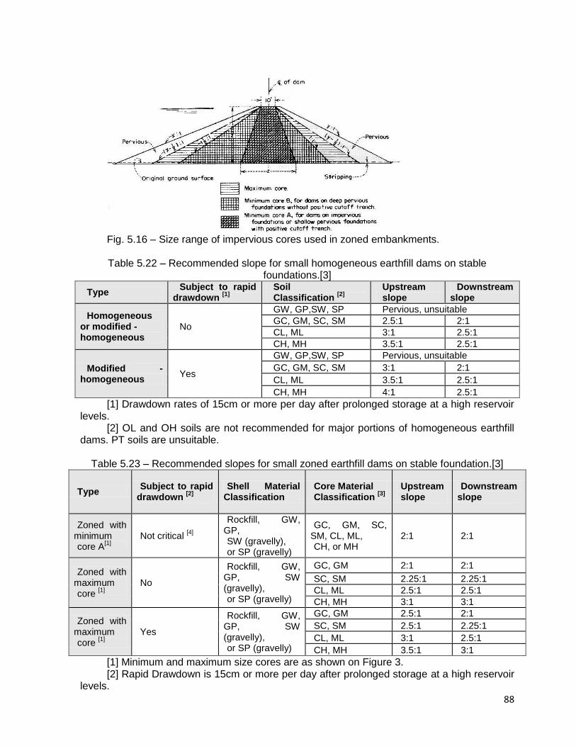
88
Fig. 5.16 – Size range of impervious cores used in zoned embankments. Table 5.22 – Recommended slope for small homogeneous earthfill dams on stable
foundations.[3]
Type Subject to rapid
drawdown [1]
Soil Classification
[2]
Upstream slope
Downstream slope
Homogeneous or modified - homogeneous
No
GW, GP,SW, SP Pervious, unsuitable
GC, GM, SC, SM 2.5:1 2:1
CL, ML 3:1 2.5:1
CH, MH 3.5:1 2.5:1
Modified - homogeneous
Yes
GW, GP,SW, SP Pervious, unsuitable
GC, GM, SC, SM 3:1 2:1
CL, ML 3.5:1 2.5:1
CH, MH 4:1 2.5:1
[1] Drawdown rates of 15cm or more per day after prolonged storage at a high reservoir levels.
[2] OL and OH soils are not recommended for major portions of homogeneous earthfill dams. PT soils are unsuitable.
Table 5.23 – Recommended slopes for small zoned earthfill dams on stable foundation.[3]
Type Subject to rapid
drawdown [2]
Shell Material
Classification Core Material Classification
[3]
Upstream slope
Downstream slope
Zoned with minimum core A
[1]
Not critical [4]
Rockfill, GW, GP, SW (gravelly), or SP (gravelly)
GC, GM, SC, SM, CL, ML, CH, or MH
2:1 2:1
Zoned with maximum core
[1]
No
Rockfill, GW, GP, SW (gravelly), or SP (gravelly)
GC, GM 2:1 2:1
SC, SM 2.25:1 2.25:1
CL, ML 2.5:1 2.5:1
CH, MH 3:1 3:1
Zoned with maximum core
[1]
Yes
Rockfill, GW, GP, SW (gravelly), or SP (gravelly)
GC, GM 2.5:1 2:1
SC, SM 2.5:1 2.25:1
CL, ML 3:1 2.5:1
CH, MH 3.5:1 3:1
[1] Minimum and maximum size cores are as shown on Figure 3. [2] Rapid Drawdown is 15cm or more per day after prolonged storage at a high reservoir
levels.
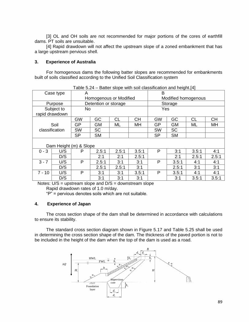
89
[3] OL and OH soils are not recommended for major portions of the cores of earthfill dams. PT soils are unsuitable.
[4] Rapid drawdown will not affect the upstream slope of a zoned embankment that has a large upstream pervious shell.
3. Experience of Australia
For homogenous dams the following batter slopes are recommended for embankments
built of soils classified according to the Unified Soil Classification system
Table 5.24 – Batter slope with soil classification and height.[4]
Case type A Homogenous or Modified
B Modified homogenous
Purpose Detention or storage Storage
Subject to rapid drawdown
No Yes
Soil classification
GW GC CL CH GW GC CL CH
GP GM ML MH GP GM ML MH
SW SC SW SC
SP SM SP SM
Dam Height (m) & Slope
0 - 3 U/S P 2.5:1 2.5:1 3.5:1 P 3:1 3.5:1 4:1
D/S 2:1 2:1 2.5:1 2:1 2.5:1 2.5:1
3 - 7 U/S P 2.5:1 3:1 3:1 P 3.5:1 4:1 4:1
D/S 2.5:1 2.5:1 3:1 2.5:1 3:1 3:1
7 - 10 U/S P 3:1 3:1 3.5:1 P 3.5:1 4:1 4:1
D/S 3:1 3:1 3:1 3:1 3.5:1 3.5:1
Notes: U/S = upstream slope and D/S = downstream slope Rapid drawdown rates of 1.0 m/day. “P” = pervious denotes soils which are not suitable.
4. Experience of Japan The cross section shape of the dam shall be determined in accordance with calculations
to ensure its stability. The standard cross section diagram shown in Figure 5.17 and Table 5.25 shall be used
in determining the cross section shape of the dam. The thickness of the paved portion is not to be included in the height of the dam when the top of the dam is used as a road.
B
H H1
HWL FWL h1
h2
d4 d1
h3
b
h4
d3
d2
Foundation layer
Impervious core
1:n
1:n
1:n
1:n
1 3
21 3
1:n 1 3
F n
F nF n
F n
1: n4
H2
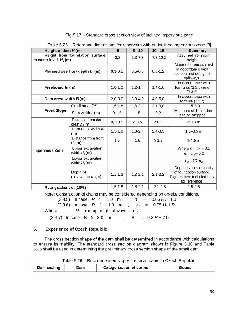
90
Fig.5.17 – Standard cross section view of inclined impervious zone
Table 5.25 – Reference dimensions for reservoirs with an inclined impervious zone.[8]
Height of dam H (m) - 5 5 - 10 10 - 15 Summary
Height from foundation surface to water level H1 (m)
-3,3 3,3-7,8 7,8-12,2 Assumed from dam
height
Planned overflow depth h1 (m) 0,3-0,5 0,5-0,8 0,8-1,2
Major differences exist in accordance with
position and design of spillways.
Freeboard h2 (m) 1,0-1,2 1,2-1,4 1,4-1,6 In accordance with
formulas (3.3.5) and (3.3.6)
Dam crest width B (m) 2,0-3,0 3,0-4,0 4,0-5,0 In accordance with
formula (3.3.7)
Front Slope
Gradient n1 (%) 1,5-1,8 1,8-2,1 2,1-3,0 1.5-3.0
Step width b (m) 0-1,5 1,5 0,2 Minimum of 1 m if dam
is to be stepped
Impervious Zone
Distance from dam crest h3 (m)
0,3-0,5 ≥ 0,5 ≥ 0,5 ≥ 0.3 m
Dam crest width d1
(m) 1,5-1,8 1,8-2,4 2,4-3,5 1.5–3.5 m
Distance from front d4 (m)
1,5 1,5 ≥ 1,5 ≥ 1.5 m
Upper excavation width d2 (m)
Where n2=n1-0.1
n3=n2-0.2
Lower excavation width d3 (m)
d3=1/2 d2
Depth of excavation h4 (m)
1,1-1,3 1,3-2,1 2,1-3,2
Depends on soil quality of foundation surface.
Figures here included only for reference.
Rear gradient n4 (10%) 1,5-1,8 1,8-2,1 2,1-2,5 1.5-2.5
Note: Construction of drains may be considered depending on on-site conditions.
(3.3.5) In case R ≦ 1.0 m , h2 = 0.05 H2+1.0
(3.3.6) In case R > 1.0 m , h2 = 0.05 H2+R
Where R :run-up height of waves(m)
(3.3.7) In case B ≥ 3.0 m , B = 0.2 H + 2.0
5. Experience of Czech Republic
The cross section shape of the dam shall be determined in accordance with calculations
to ensure its stability. The standard cross section diagram shown in Figure 5.18 and Table 5.26 shall be used in determining the preliminary cross section shape of the small dam
Table 5.26 – Recommended slopes for small dams in Czech Republic.
Dam sealing Dam Categorization of earths Slopes
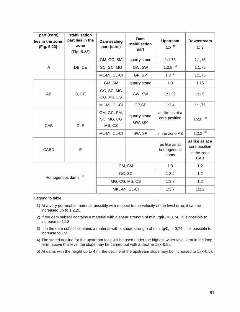
91
part (core)
lies in the zone
(Fig. 5.23)
stabilization
part lies in the
zone
(Fig. 5.23)
Dam sealing
part (core)
Dam
stabilization
part
Upstream
1:x 4)
Downstream
1: y
A DB, CE
GM, GC, SM quarry stone 1:1,75 1:1,15
SC, GC, MG GW, SW 1:2,8 1)
1:1,75
ML-MI, CL-CI GP, SP 1:3 1)
1:1,75
AB D, CE
GM, SM quarry stone 1:3 1,15
GC, SC, MG
CG, MS, CS GW, SW 1:1,32 1:1,5
ML-MI, CL-CI GP,SP 1:3,4 1:1,75
CAB
D, E
GM, GC, SM,
SC, MG, CG
MS, CS
quarry stone
GW, GP
as like as at a
core position
in the zone AB
1:2,0 2)
ML-MI, CL-CI SW, SP 1:2,2 3)
CABD E
as like as at
homogenous
dams
as like as at a
core position
in the zone
CAB
Homogenous dams 5)
GM, SM 1:3 1:2
GC, SC 1:3,4 1:2
MG, CG, MS, CS 1:3,3 1:2
MKL-MI, CL-CI 1:3,7 1:2,2
Legend to table:
1) At a very permeable material, possibly with respect to the velocity of the level drop, it can be increased up to 1:2,25.
2) If the dam subsoil contains a material with a shear strength of min. tgΦsf = 0,74, it is possible to increase to 1:18
3) If in the dam subsoil contains a material with a shear strength of min. tgΦsf = 0,74, it is possible to increase to 1:2
4) The stated decline for the upstream face will be used under the highest water level kept in the long term, above this level the slope may be carried out with a decline 1:(x-0,5).
5) At dams with the height up to 4 m, the decline of the upstream slope may be increased to 1:(x-0,5).
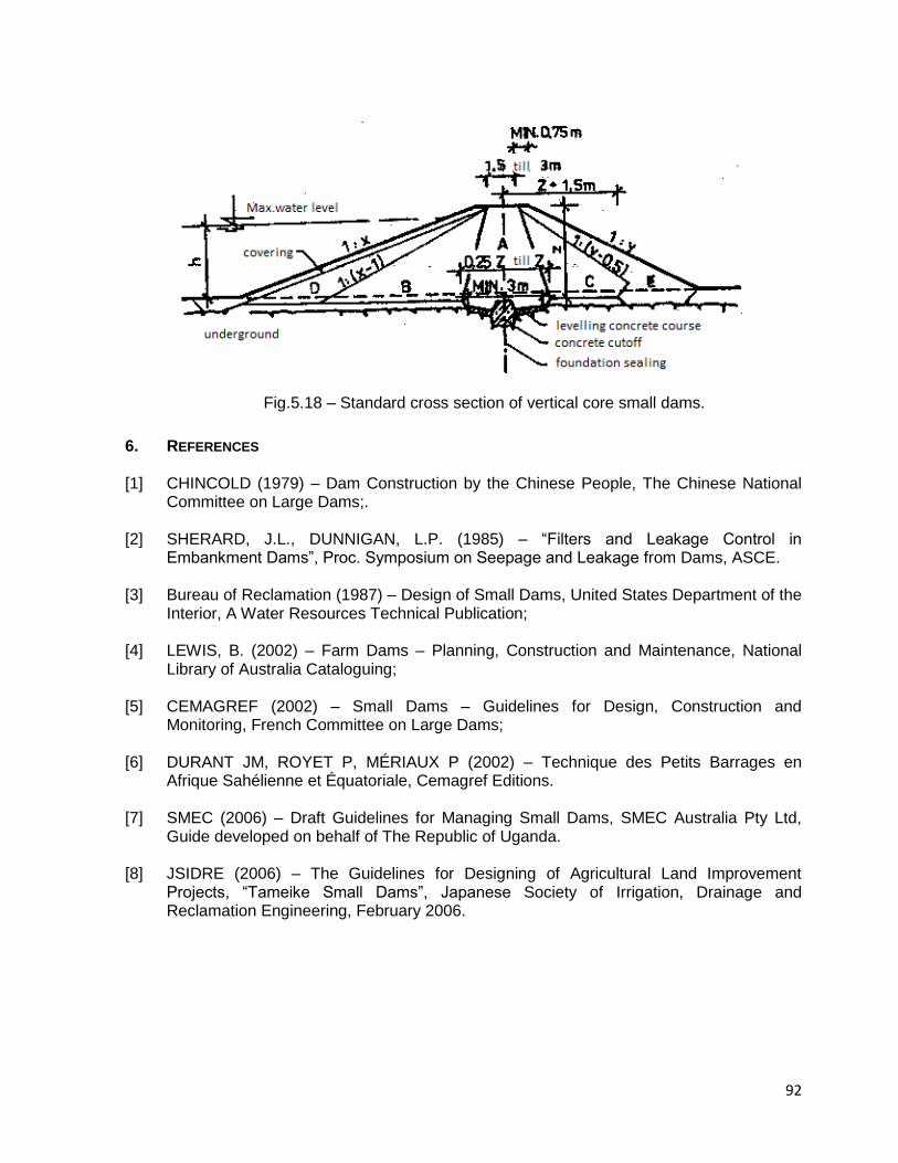
92
Fig.5.18 – Standard cross section of vertical core small dams.
6. REFERENCES
[1] CHINCOLD (1979) – Dam Construction by the Chinese People, The Chinese National
Committee on Large Dams;. [2] SHERARD, J.L., DUNNIGAN, L.P. (1985) – “Filters and Leakage Control in
Embankment Dams”, Proc. Symposium on Seepage and Leakage from Dams, ASCE. [3] Bureau of Reclamation (1987) – Design of Small Dams, United States Department of the
Interior, A Water Resources Technical Publication; [4] LEWIS, B. (2002) – Farm Dams – Planning, Construction and Maintenance, National
Library of Australia Cataloguing; [5] CEMAGREF (2002) – Small Dams – Guidelines for Design, Construction and
Monitoring, French Committee on Large Dams; [6] DURANT JM, ROYET P, MÉRIAUX P (2002) – Technique des Petits Barrages en
Afrique Sahélienne et Équatoriale, Cemagref Editions. [7] SMEC (2006) – Draft Guidelines for Managing Small Dams, SMEC Australia Pty Ltd,
Guide developed on behalf of The Republic of Uganda. [8] JSIDRE (2006) – The Guidelines for Designing of Agricultural Land Improvement
Projects, “Tameike Small Dams”, Japanese Society of Irrigation, Drainage and Reclamation Engineering, February 2006.
93
6. GUIDELINES ON SURVEILLANCE OF SMALL DAMS 6.1 INTRODUCTION
The owners and project engineers, who are responsible for the safe and economic
operation of dams need to be adequately informed about the following: How to detect, measure, evaluate and remedy problems which may adversely affect
safe and economic performance of the dam, its appurtenances and equipment? How to comply with governmental regulations pertaining to dam safety? How to integrate inspection and Dam Performance Evaluation Program activities, with
operation and maintenance of the project? What type of organization and assignment of responsibility for inspection, data
collection and reporting would be practical and effective in promoting safe and economical project operation?
What are the desired qualifications of a dam safety inspector? What should be the frequency and scope of visual inspections? When the inspection reports and monitoring data are received, how to evaluate and
analyze the data and what follow-up actions to take? What are the remedial actions which could be taken to alleviate or correct certain
problems to restore the structure to an acceptable operating condition?
6.2 SAFETY SURVEILLANCE It is always important to a dam owner to play an important role in the dam safety
process. Frequent visits to the dam are needed to enable to observe any problem that may be developing and affecting the dam safety.
If the dam fails, the dam owner are likely to be liable for any loss of life, injury or
damage which results from the accident; Even if a failure does not cause damage outside his property, the cost of remedial
work can easily exceed the original construction cost of the dam. A property owner who is planning to build a new dam must minimize the possibility of
failure, attached liability and could also contribute to the safety of the dam by: Having the dam designed, constructed and supervised by a qualified and experienced
professional engineer; Establishing a program of regular inspections (surveillance) and periodic
maintenance, including the keeping of appropriate records; Monitoring conditions that may affect the safety of dams, be able to recognize the
signs of potential problems and imminent failure; Having an experienced dam engineer investigating any unusual conditions which
could result in total or particle failure; Knowing what to do and who to contact when such problem appear.
94
6.3 SURVEILLANCE PRACTICES Safety surveillance of a dam is a program of regular visual inspection using simple
equipment and technique. It is the most economically efficient means of ensuring the long-term safety and survival of the dam. Its primary purpose is to monitor the condition and performance of the dam and its surroundings, and to ensure maintenance before the development of potential hazards.
The procedure is unique to each dam but essentially it consists of: Regular and close examination of the entire dam surface and its immediate
surroundings; Appropriate measurements of cracks, surface erosion, soil transported by leakage,
etc. Keeping concise and accurate records of observations. For continuity and consistency of approach, it is recommended that the same person
should normally carry out each type of inspection. When necessary, an experienced engineer need to be brought in, to inspect or advice about particular problems.
To be effective, surveillance requires a good knowledge of the dam (data on
construction, reports on all work done and inspections, etc.), and the guarantee of good maintenance and surveillance of any work already done. It is very important to gather all known data about the dam concerning both its construction (surveys, design, construction, as-built documents) and its later life (operation, reports on inspections, reports on maintenance work, monitoring data, typical incidents, etc.).
The following items are useful when conducting an inspection: Notebook or diary and pencil to write down observations about the main points; Digital camera to provide photos of the particular anomalies and deteriorations; A tape to take some measurement allowing the location of wet areas, cracks and
slumps for future comparisons. The quality of the visual observations, and therefore dam safety can only be achieved by
sufficient motivation and some technical training for the personnel involved.
6.3.1 Inspection Procedures The procedure for dam safety surveillance is unique to each dam but consists essentially
of regular, close and systematic examination of the entire surface of the dam and it immediate surroundings. In the case of small dams, especially those dams in which owner have not sought appropriate advice, there may be a perception that above procedure are unnecessary, or an unproductive use of time. There may also be a lack of knowledge of what needs to be done.
For a small dam it is prudent to obtain professional engineering advice to set up the first
program, using a simple set of pro-forma check-list to record observations.
Smaller utility companies or municipal entities that own and operate small dams may not have in-house engineering capability and staff to form their own performance program. In such
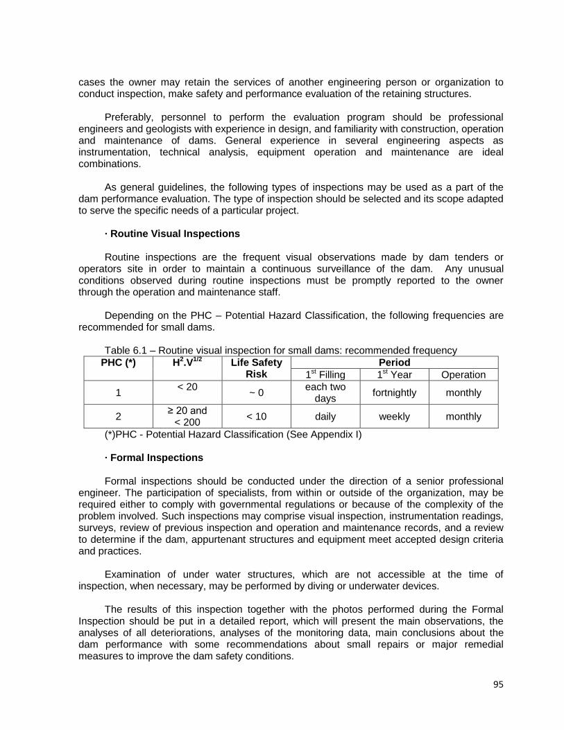
95
cases the owner may retain the services of another engineering person or organization to conduct inspection, make safety and performance evaluation of the retaining structures.
Preferably, personnel to perform the evaluation program should be professional
engineers and geologists with experience in design, and familiarity with construction, operation and maintenance of dams. General experience in several engineering aspects as instrumentation, technical analysis, equipment operation and maintenance are ideal combinations.
As general guidelines, the following types of inspections may be used as a part of the
dam performance evaluation. The type of inspection should be selected and its scope adapted to serve the specific needs of a particular project.
· Routine Visual Inspections Routine inspections are the frequent visual observations made by dam tenders or
operators site in order to maintain a continuous surveillance of the dam. Any unusual conditions observed during routine inspections must be promptly reported to the owner through the operation and maintenance staff.
Depending on the PHC – Potential Hazard Classification, the following frequencies are
recommended for small dams. Table 6.1 – Routine visual inspection for small dams: recommended frequency
PHC (*) H2.V1/2 Life Safety Risk
Period
1st Filling 1st Year Operation
1 < 20
~ 0
each two days
fortnightly monthly
2 ≥ 20 and
< 200 < 10 daily weekly monthly
(*)PHC - Potential Hazard Classification (See Appendix I) · Formal Inspections Formal inspections should be conducted under the direction of a senior professional
engineer. The participation of specialists, from within or outside of the organization, may be required either to comply with governmental regulations or because of the complexity of the problem involved. Such inspections may comprise visual inspection, instrumentation readings, surveys, review of previous inspection and operation and maintenance records, and a review to determine if the dam, appurtenant structures and equipment meet accepted design criteria and practices.
Examination of under water structures, which are not accessible at the time of
inspection, when necessary, may be performed by diving or underwater devices. The results of this inspection together with the photos performed during the Formal
Inspection should be put in a detailed report, which will present the main observations, the analyses of all deteriorations, analyses of the monitoring data, main conclusions about the dam performance with some recommendations about small repairs or major remedial measures to improve the dam safety conditions.
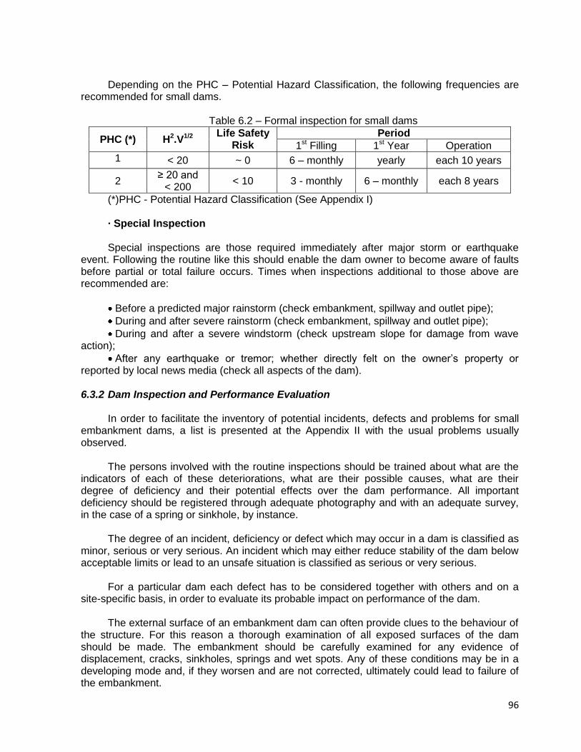
96
Depending on the PHC – Potential Hazard Classification, the following frequencies are recommended for small dams.
Table 6.2 – Formal inspection for small dams
PHC (*) H2.V1/2 Life Safety
Risk Period
1st Filling 1st Year Operation
1 < 20 ~ 0 6 – monthly yearly each 10 years
2 ≥ 20 and
< 200 < 10 3 - monthly 6 – monthly each 8 years
(*)PHC - Potential Hazard Classification (See Appendix I) · Special Inspection Special inspections are those required immediately after major storm or earthquake
event. Following the routine like this should enable the dam owner to become aware of faults before partial or total failure occurs. Times when inspections additional to those above are recommended are:
Before a predicted major rainstorm (check embankment, spillway and outlet pipe);
During and after severe rainstorm (check embankment, spillway and outlet pipe);
During and after a severe windstorm (check upstream slope for damage from wave action);
After any earthquake or tremor; whether directly felt on the owner’s property or reported by local news media (check all aspects of the dam).
6.3.2 Dam Inspection and Performance Evaluation
In order to facilitate the inventory of potential incidents, defects and problems for small
embankment dams, a list is presented at the Appendix II with the usual problems usually observed.
The persons involved with the routine inspections should be trained about what are the
indicators of each of these deteriorations, what are their possible causes, what are their degree of deficiency and their potential effects over the dam performance. All important deficiency should be registered through adequate photography and with an adequate survey, in the case of a spring or sinkhole, by instance.
The degree of an incident, deficiency or defect which may occur in a dam is classified as
minor, serious or very serious. An incident which may either reduce stability of the dam below acceptable limits or lead to an unsafe situation is classified as serious or very serious.
For a particular dam each defect has to be considered together with others and on a
site-specific basis, in order to evaluate its probable impact on performance of the dam. The external surface of an embankment dam can often provide clues to the behaviour of
the structure. For this reason a thorough examination of all exposed surfaces of the dam should be made. The embankment should be carefully examined for any evidence of displacement, cracks, sinkholes, springs and wet spots. Any of these conditions may be in a developing mode and, if they worsen and are not corrected, ultimately could lead to failure of the embankment.
97
Surface displacement on an embankment often can be detected by visual examination.
Sighting along the line of embankment roads, parapet walls, utility lines, guardrails, longitudinal conduits, or other lineaments parallel or concentric to the embankment axis can sometimes identify surface movements of the embankment. The crest should be examined for depressions and crack patterns that could indicate sliding settlement, or bulging movements. The upstream and downstream slopes and areas downstream of the embankment should be examined for any sign of bulging, depression, or other variance from smooth, uniform face planes.
Cracks on the surface of an embankment can be indicative of potentially unsafe
conditions. Surface cracks are often caused by desiccation and shrinkage of materials near the surface of the embankment; however, the depth and orientation of the cracks should be determined for a better understanding of their cause. Openings or escarpments on the embankment crest or slopes can identity slides and a close examination of these areas should be made to outline the location and extent of the slide mass. Surface cracks near the embankment abutment contact, and contacts with other structures can be an indication of settlement of the embankment and, if severe enough, a path for seepage can develop along the contact. Therefore, these locations must be thoroughly examined. Cracks can also indicate differential settlement between embankment zones.
The downstream face and toe of the dam areas downstream of the embankment, and
natural abutment should be examined for wet spots, boils, depressions, sinkholes, or springs which may indicate concentrated or excessive seepage through the dam and abutment.
Drainage systems should be inspected for increased or decreased flow and for any
obstructions which could plug the drains. In addition to verifying anticipated embankment and foundation performance, instrumentation also can be an indicator of developing unsafe conditions.
6.3.3 Inspections After Earthquakes
If an earthquake is observed at or near a dam, or one has been reported to have
occurred, with a Richter magnitude greater than and within a radial distance as set out in the table below, a detailed visual inspection of the dam have to be performed, according to the ICOLD Bulletin 62, in revision at 2009, according to the following list:
Richter Magnitude Distance to Dam > 4.0 ≤ 25 km > 5.0 ≤ 50 km > 6.0 ≤ 80 km > 7.0 ≤ 125 km > 8.0 ≤ 200 km Note: these combinations have been chosen such that a significant intensity level is
expected to have been experienced at the dam site. An alternative trigger for inspection could for example be an intensity of shaking of greater than MMI 4 experienced at a dam site.
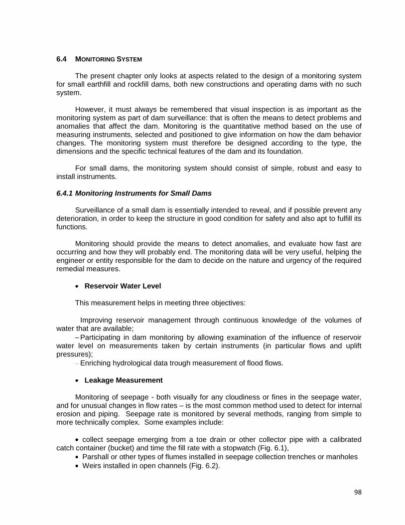
98
6.4 MONITORING SYSTEM The present chapter only looks at aspects related to the design of a monitoring system
for small earthfill and rockfill dams, both new constructions and operating dams with no such system.
However, it must always be remembered that visual inspection is as important as the
monitoring system as part of dam surveillance: that is often the means to detect problems and anomalies that affect the dam. Monitoring is the quantitative method based on the use of measuring instruments, selected and positioned to give information on how the dam behavior changes. The monitoring system must therefore be designed according to the type, the dimensions and the specific technical features of the dam and its foundation.
For small dams, the monitoring system should consist of simple, robust and easy to
install instruments.
6.4.1 Monitoring Instruments for Small Dams Surveillance of a small dam is essentially intended to reveal, and if possible prevent any
deterioration, in order to keep the structure in good condition for safety and also apt to fulfill its functions.
Monitoring should provide the means to detect anomalies, and evaluate how fast are
occurring and how they will probably end. The monitoring data will be very useful, helping the engineer or entity responsible for the dam to decide on the nature and urgency of the required remedial measures.
Reservoir Water Level This measurement helps in meeting three objectives:
Improving reservoir management through continuous knowledge of the volumes of water that are available;
Participating in dam monitoring by allowing examination of the influence of reservoir water level on measurements taken by certain instruments (in particular flows and uplift pressures);
Enriching hydrological data trough measurement of flood flows.
Leakage Measurement Monitoring of seepage - both visually for any cloudiness or fines in the seepage water,
and for unusual changes in flow rates – is the most common method used to detect for internal erosion and piping. Seepage rate is monitored by several methods, ranging from simple to more technically complex. Some examples include:
collect seepage emerging from a toe drain or other collector pipe with a calibrated catch container (bucket) and time the fill rate with a stopwatch (Fig. 6.1),
Parshall or other types of flumes installed in seepage collection trenches or manholes
Weirs installed in open channels (Fig. 6.2).
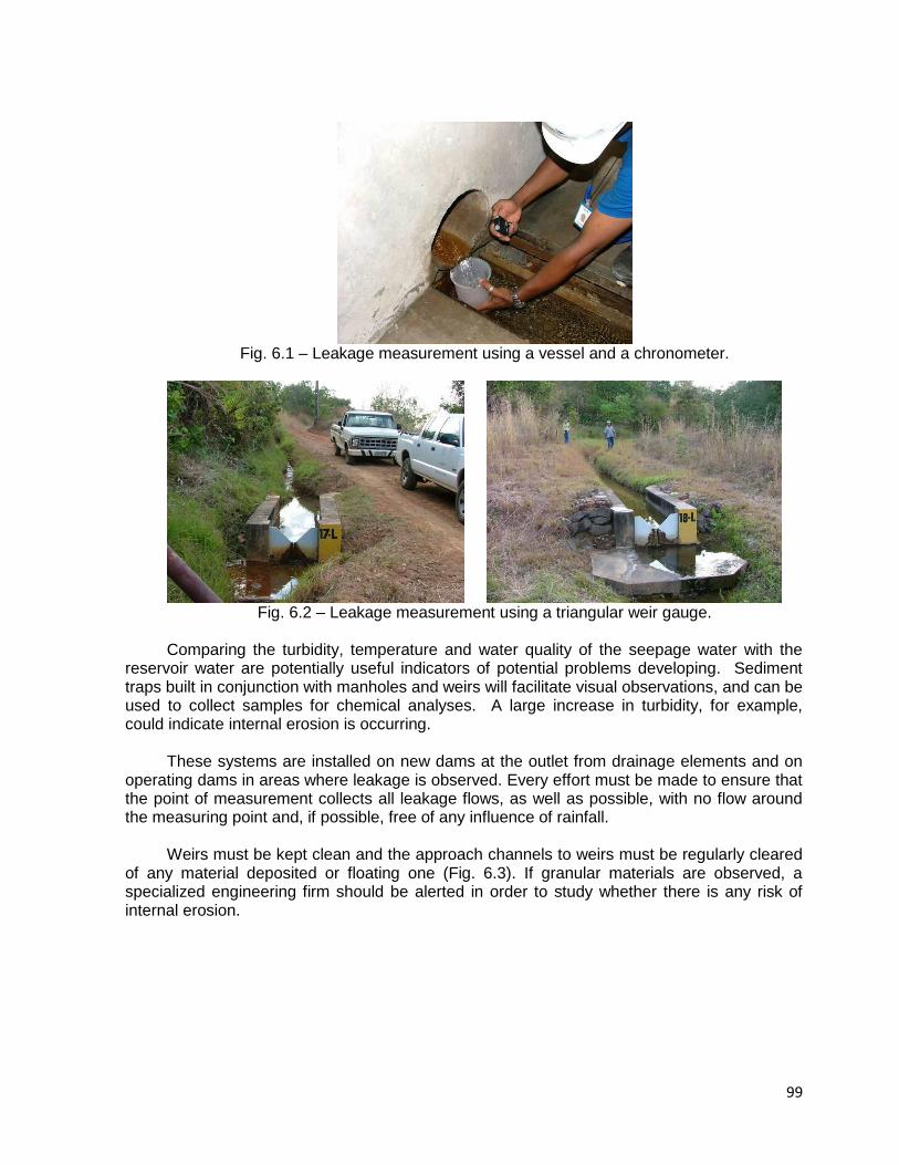
99
Fig. 6.1 – Leakage measurement using a vessel and a chronometer.
Fig. 6.2 – Leakage measurement using a triangular weir gauge.
Comparing the turbidity, temperature and water quality of the seepage water with the
reservoir water are potentially useful indicators of potential problems developing. Sediment traps built in conjunction with manholes and weirs will facilitate visual observations, and can be used to collect samples for chemical analyses. A large increase in turbidity, for example, could indicate internal erosion is occurring.
These systems are installed on new dams at the outlet from drainage elements and on
operating dams in areas where leakage is observed. Every effort must be made to ensure that the point of measurement collects all leakage flows, as well as possible, with no flow around the measuring point and, if possible, free of any influence of rainfall.
Weirs must be kept clean and the approach channels to weirs must be regularly cleared
of any material deposited or floating one (Fig. 6.3). If granular materials are observed, a specialized engineering firm should be alerted in order to study whether there is any risk of internal erosion.
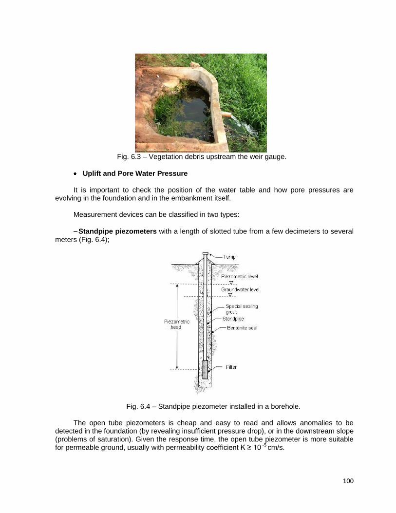
100
Fig. 6.3 – Vegetation debris upstream the weir gauge.
Uplift and Pore Water Pressure It is important to check the position of the water table and how pore pressures are
evolving in the foundation and in the embankment itself. Measurement devices can be classified in two types:
Standpipe piezometers with a length of slotted tube from a few decimeters to several meters (Fig. 6.4);
Fig. 6.4 – Standpipe piezometer installed in a borehole.
The open tube piezometers is cheap and easy to read and allows anomalies to be
detected in the foundation (by revealing insufficient pressure drop), or in the downstream slope (problems of saturation). Given the response time, the open tube piezometer is more suitable for permeable ground, usually with permeability coefficient K ≥ 10 -5 cm/s.
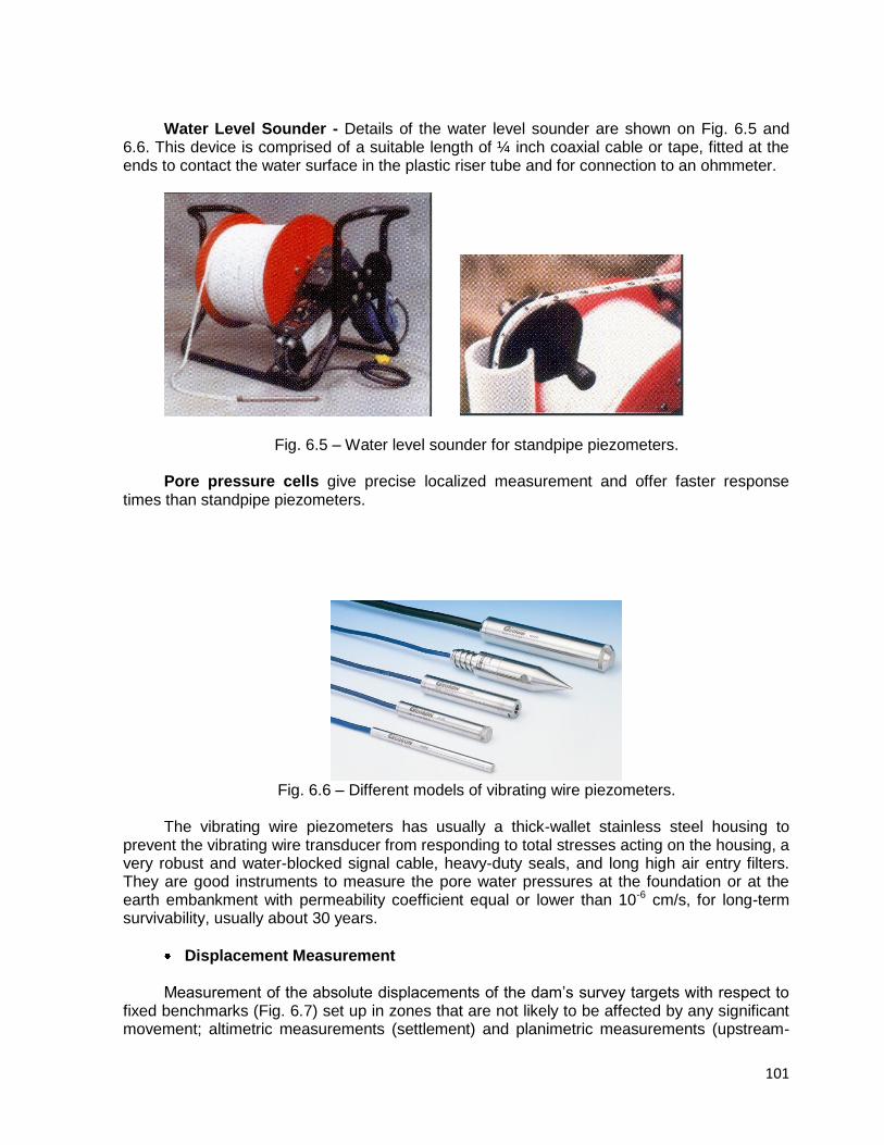
101
Water Level Sounder - Details of the water level sounder are shown on Fig. 6.5 and 6.6. This device is comprised of a suitable length of ¼ inch coaxial cable or tape, fitted at the ends to contact the water surface in the plastic riser tube and for connection to an ohmmeter.
Fig. 6.5 – Water level sounder for standpipe piezometers. Pore pressure cells give precise localized measurement and offer faster response
times than standpipe piezometers.
Fig. 6.6 – Different models of vibrating wire piezometers.
The vibrating wire piezometers has usually a thick-wallet stainless steel housing to
prevent the vibrating wire transducer from responding to total stresses acting on the housing, a very robust and water-blocked signal cable, heavy-duty seals, and long high air entry filters. They are good instruments to measure the pore water pressures at the foundation or at the earth embankment with permeability coefficient equal or lower than 10-6 cm/s, for long-term survivability, usually about 30 years.
Displacement Measurement Measurement of the absolute displacements of the dam’s survey targets with respect to
fixed benchmarks (Fig. 6.7) set up in zones that are not likely to be affected by any significant movement; altimetric measurements (settlement) and planimetric measurements (upstream-
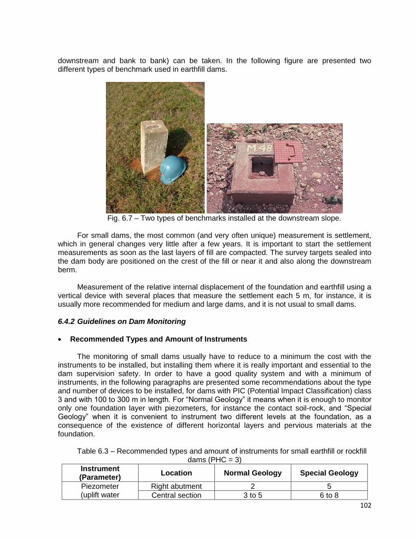
102
downstream and bank to bank) can be taken. In the following figure are presented two different types of benchmark used in earthfill dams.
Fig. 6.7 – Two types of benchmarks installed at the downstream slope.
For small dams, the most common (and very often unique) measurement is settlement,
which in general changes very little after a few years. It is important to start the settlement measurements as soon as the last layers of fill are compacted. The survey targets sealed into the dam body are positioned on the crest of the fill or near it and also along the downstream berm.
Measurement of the relative internal displacement of the foundation and earthfill using a
vertical device with several places that measure the settlement each 5 m, for instance, it is usually more recommended for medium and large dams, and it is not usual to small dams.
6.4.2 Guidelines on Dam Monitoring
Recommended Types and Amount of Instruments The monitoring of small dams usually have to reduce to a minimum the cost with the
instruments to be installed, but installing them where it is really important and essential to the dam supervision safety. In order to have a good quality system and with a minimum of instruments, in the following paragraphs are presented some recommendations about the type and number of devices to be installed, for dams with PIC (Potential Impact Classification) class 3 and with 100 to 300 m in length. For “Normal Geology” it means when it is enough to monitor only one foundation layer with piezometers, for instance the contact soil-rock, and “Special Geology” when it is convenient to instrument two different levels at the foundation, as a consequence of the existence of different horizontal layers and pervious materials at the foundation.
Table 6.3 – Recommended types and amount of instruments for small earthfill or rockfill
dams (PHC = 3)
Instrument (Parameter)
Location Normal Geology Special Geology
Piezometer (uplift water
Right abutment 2 5
Central section 3 to 5 6 to 8

103
pressure) Left abutment 2 5
Weir gauge (seepage water)
Right abutment - 1
Central section 2 2
Left abutment - 1
Bench marks (Displacements)
Crest Lc/50 Lc/20
Berm (eventual) Lb/50 Lb/20
(*) Obs. Lc and Lb correspond to the length of the crest and the downstream berm in meters.
It is important to point out that the total amount of instruments recommended in this table
is the minimum, and in the case of dams with foundations deserving special attention, with an intricate geology incorporating faults and folds directly under the dam, it is important to install some more instruments.
Considering that for small dams there are usually small support for their monitoring
maintenance it is recommended to install standpipe piezometers, if possible, which normally present a performance compatible with that of the dam itself. These instruments can be successfully installed in soils with a permeability coefficient higher or equal to 10-6 cm/s, as already discussed. It is also important to install one or more weir gauge to monitor the leakage.
Recommendations for Piezometer Measurements In the location of the piezometers at the dam foundation, impervious core or horizontal
filter, the following recommendations are important to be attended: To install foundation piezometers upstream and downstream of the grout curtain or
the cutoff trench, in order to calculate its performance; Perform the installation of a piezometer at the upstream drain blanket, in order to
know the water head at the drainage system; In dams with PHC = 3 install some piezometers at the central core, near the axis of
the dam, to evaluate the maximum pore pressures and the phreatic line location; If the geological investigations showed a fault crossing the foundation from upstream
to downstream it is very important to install some foundation piezometers along this fault, which usually implies in a preferential seepage way.
In the following sketch and expressions are presented the location of a grout curtain or the cutoff trench at the foundation of an earthfill dam, and how it is possible to calculate its efficiency considering the water head drop.
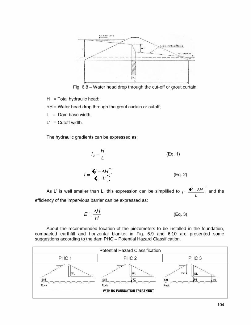
104
Fig. 6.8 – Water head drop through the cut-off or grout curtain.
H = Total hydraulic head;
∆H = Water head drop through the grout curtain or cutoff;
L = Dam base width;
L’ = Cutoff width.
The hydraulic gradients can be expressed as:
L
HI0 (Eq. 1)
'LL
HHI (Eq. 2)
As L’ is well smaller than L, this expression can be simplified to L
HHI , and the
efficiency of the impervious barrier can be expressed as:
H
HE (Eq. 3)
About the recommended location of the piezometers to be installed in the foundation,
compacted earthfill and horizontal blanket in Fig. 6.9 and 6.10 are presented some suggestions according to the dam PHC – Potential Hazard Classification.
Potential Hazard Classification
PHC 1 PHC 2 PHC 3
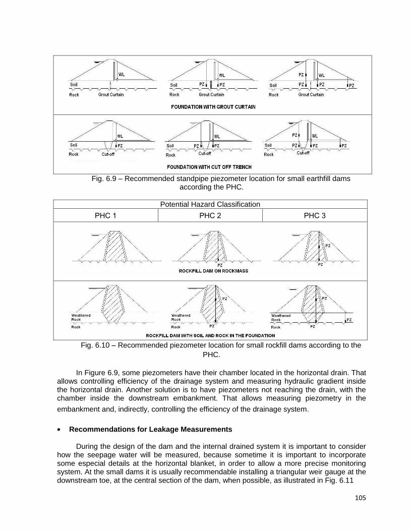
105
Fig. 6.9 – Recommended standpipe piezometer location for small earthfill dams
according the PHC.
Potential Hazard Classification
PHC 1 PHC 2 PHC 3
Fig. 6.10 – Recommended piezometer location for small rockfill dams according to the
PHC.
In Figure 6.9, some piezometers have their chamber located in the horizontal drain. That allows controlling efficiency of the drainage system and measuring hydraulic gradient inside the horizontal drain. Another solution is to have piezometers not reaching the drain, with the chamber inside the downstream embankment. That allows measuring piezometry in the
embankment and, indirectly, controlling the efficiency of the drainage system.
Recommendations for Leakage Measurements During the design of the dam and the internal drained system it is important to consider
how the seepage water will be measured, because sometime it is important to incorporate some especial details at the horizontal blanket, in order to allow a more precise monitoring system. At the small dams it is usually recommendable installing a triangular weir gauge at the downstream toe, at the central section of the dam, when possible, as illustrated in Fig. 6.11
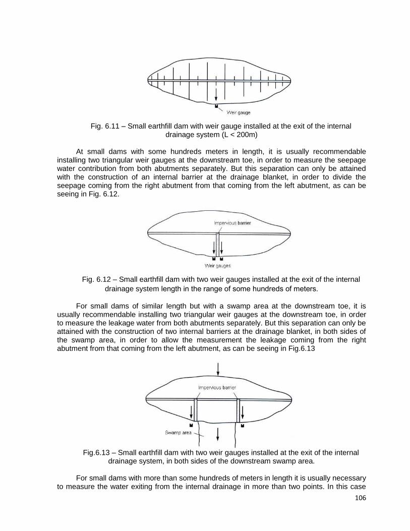
106
Fig. 6.11 – Small earthfill dam with weir gauge installed at the exit of the internal
drainage system (L < 200m) At small dams with some hundreds meters in length, it is usually recommendable
installing two triangular weir gauges at the downstream toe, in order to measure the seepage water contribution from both abutments separately. But this separation can only be attained with the construction of an internal barrier at the drainage blanket, in order to divide the seepage coming from the right abutment from that coming from the left abutment, as can be seeing in Fig. 6.12.
Fig. 6.12 – Small earthfill dam with two weir gauges installed at the exit of the internal
drainage system length in the range of some hundreds of meters.
For small dams of similar length but with a swamp area at the downstream toe, it is
usually recommendable installing two triangular weir gauges at the downstream toe, in order to measure the leakage water from both abutments separately. But this separation can only be attained with the construction of two internal barriers at the drainage blanket, in both sides of the swamp area, in order to allow the measurement the leakage coming from the right abutment from that coming from the left abutment, as can be seeing in Fig.6.13
Fig.6.13 – Small earthfill dam with two weir gauges installed at the exit of the internal
drainage system, in both sides of the downstream swamp area. For small dams with more than some hundreds of meters in length it is usually necessary
to measure the water exiting from the internal drainage in more than two points. In this case

107
the others weir gauges need to be installed at the lower points of the foundation, along the longitudinal section, in which there are the possibility of water leakage, after the reservoir filling. Usually it is not possible to evaluate correctly all the places in which it will have water at the dam toe previously, then it is recommended to install the weir gauges of the central section before the reservoir filling, and the other during or after the reservoir filling.
6.4.3 Data Analysis and Reporting
Data management and analysis are fundamental to understanding the behavior of the
monitored dam, for detecting unsafe development, and for determining the performance of the instrument system. The plan should indicate the frequency of data collection, the extent and timeliness of processing, the level of analysis and the reporting requirements.
Data Management The management of data consists of data collection, reduction and processing, and
reporting. Data collection should begin with a well-defined established schedule. Data collection procedures should adhere to the following guidelines:
Data will be most consistent if collected by the same person; Using the same device or readout unit to read an instrument every time give the most
consistent readings; Instrumentation data should include the instrument reading and also any information
that identifies the project, instrument, reader, date, visual observations, climate, remarks, and any site conditions that might affect the value of the reading;
Recording reading in field books allows for comparison of current readings with
previous readings at the time the readings are collected. The readings in field books should be
transferred to data sheets or computer files as soon as possible after being obtained;
Readings that exceed established levels should be reported immediately. The first
action should be to control the condition of the measuring device and to perform a new measurement. If the measurement is confirmed, appropriate personnel should be notified because a change in instrument reading or in visual observation reveals that a problem or dangerous situation has occurred, or is occurring.
Data processing and reduction consists of converting the raw data into meaningful engineering parameters necessary for graphical presentation, analysis and interpretation. Calibration constants may be needed to convert the field reading to engineering values.
Checking for errors in instrumentation data should be accomplished at each level of collection and processing, from reading of instruments in the field to final interpretation of the instrumentation data. Instrumentation readings should be compared with ranges specified by the design office and with previous readings under similar conditions. Conformance with previous established trends should be determined.
Data Presentation – Numerically tabulated data are not conducive to detecting trends, evaluating unanticipated behavior, and comparison with design values. Plots of the data are needed to provide visual comparisons between actual and predicted behavior, a
108
visual means to detect data acquisition errors, to determine trends or cyclic effects, to compare behavior with other instruments, and to predict future behavior.
Time History Plot – Time history plots display time versus the change in parameter such as water, seepage, pore water pressure, displacements and temperature can be plotted against time.
Engineering Analysis – Data analysis is the interpretation and evaluation of the data as affected by various conditions. At every step of the analysis, the evaluator should be conscious of the potential for invalid data and the improper use of the calculations, so that incorrect interpretations are not made. Proper analysis will address two basic aspects of dam safety monitoring: performance of the instrument system, and the performance of the structure or feature that is being monitored.
An analytical technique can be considered the viewing of the current information in the
context of past experience, and the predicted behavior of the monitored feature. The review and analysis personnel should consider the following technique when analyzing the data:
Compare current data with the most recent data set to detect anomalies or instrument
malfunctions;
Compare the current data point with historical performance over a significant period of
time, to ascertain consistency of instrument performance;
Compare current data point with the initial reading for that point to determine the
magnitude of change over time;
Compare the performance of instruments installed in similar positions of the dam or
its foundations, but in different cross sections, to understand their similarities and differences;
Compare trends of behavior over time with trends predicted during design, with
values relating to calculated factors of safety, and with any other predicted behavior;
Compare trends of behavior over time with trends observed with the monitoring of
other dams, with similar type, dimensions and geological conditions.
Formal Reporting and Documentation Formal presentation of data may be different than the plotting prepared for data analysis,
because it summarize and present data to show trends, enable comparison of predicted design behavior with actual behavior, document key aspects of the instrumentation monitoring program, and identify necessary remedial measures.
The text of the report should discuss changes and identify trends and rate of change with
time. Specific values should be stated in units that are meaningful and understandable. A specific statement should be made with regard to the engineering judgment of the situation, the acceptability of the condition, and the intention for following.
Frequency of Readings The following frequency readings are recommended for the monitoring instrumentation
of small earthfill and rockfill dams, as a minimum. These frequencies need to be increased when some special events happen, such as:
Sudden upward or downward of the reservoir level, with rate higher then 1.0 m/day;

109
Earthquakes sensible at the dam site location; Severe storm at the reservoir area.
Table 6.4 – Frequency of readings for the earthfill and rockfill monitoring instruments
Parameter measured Construction
period First reservoir
filling First year of
operation Operation
Settlements Monthly Weekly Every 2 months
6 month to yearly
Uplift pressure Weekly 3 per week Weekly Fortnightly
Pore water pressure Weekly 3 per week Weekly Fortnightly
Leakage - Daily 2 per week Weekly
6.5 REFERENCES
[1] SHERARD, J.L., WOODWARD, R.J., GIZIENSKI, S.F., CLEVENGER, W.A. (1963) –
“Failures and Damages”, Chapter 2 from Earth-Rock Dams – Engineering Problems of Design and Construction, John Wiley and Sons, Inc, New York;
[2] CEDERGREN, H.R. (1973). Seepage, Drainage, and Flow Nets, 3rd ed. John Wiley &
Sons, New York. [3] BUREAU (1975) – Earth Manual – A Water Resources Technical Publication, U.S.
Department of the Interior, Bureau of Reclamation; [4] EPRI (1986) – Inspection and Performance Evaluation of Dams, EPRI – Electric Power
Research Institute, AP-5715, Project 1755-15, Final Report, San Francisco, California; [5] USACE CORPS (1995) – Instrumentation of Embankment Dams and Levees, US Army
Corps of Engineers, EM 1110-2-1908, 30 June; [6] VON THUN, J. L. (1996). “ Understanding Piping and Seepage Failures – the No. 1
Dam Safety Problem in the West,” Assoc. State Dam Safety Officials, Western Regional Conference, April 15-16, Lake Tahoe, Nevada, USA.
[7] SCHWEIGER, P. G, BINGHAM, W.B., and DREESE, T.L. (1999). “Replacement of a
Deteriorated Earthfill Dam with an RCC Gravity Dam: The Penn Forest Dam Replacement Project,” Proc. Nineteenth Annual USCOLD Lecture Series Dealing with Aging Dams, Atlanta, GA, May, United States Committee on Large Dams, Denver, CO, Colorado, USA.
[8] FOSTER, M., FELL, R., and SPANNAGLE, M. (2000). “The Statistics of Embankment
Dam Failures and Accidents,” Canadian Geotechnical Journal, Vol. 35, pp. 1000-1022. [9] LEWIS, B. (2002) – Farm Dams – Planning, Construction and Maintenance, National
Library of Australia Cataloguing;
[10] FRENCH COMMITTEE ON LARGE DAMS (2002) - Small Dams: Guidelines for Design,
Construction, and Monitoring. Coordinator Gérard Degoutte. ISBN 2-85362-551-6..

110
[11] DURAND J.M., ROYET P, MERIAUX P (2002) – Technique des Petits Barrages en
Afrique Sahélienne et Équatoriale, Cemagref Editions; [12] FELL, R., C.F. WAN, CYGANIEWICZ, J., and FOSTER, M. (2003). “Time for
Development of Internal Erosion and Piping in Embankment Dams,” Journal of Geotechnical and Geoenvironmental Engineering, Vol. 129, No. 5, April, pp. 301-315.
[13] MCCOOK, D. (2005). “A Comprehensive Discussion of Piping and Internal Erosion
Failure Mechanisms,” Proc. Assoc. State Dam Safety Officials, Annual Meeting, Sept 26-30, Phoenix, Arizona, USA.
[14] SMEC (2006) – Draft Guidelines for Managing Small Dams, SMEC Australia Pty Ltd,
Guide developed on behalf of The Republic of Uganda; [15] ROYET P.(2006) – La Surveillance et l’Entretien des Petits Barrages. [16] CSN 752410 (1997) – Standards for Small Dams Sesign, Construction, Operation and
Reconstruction, in Czech Republic.
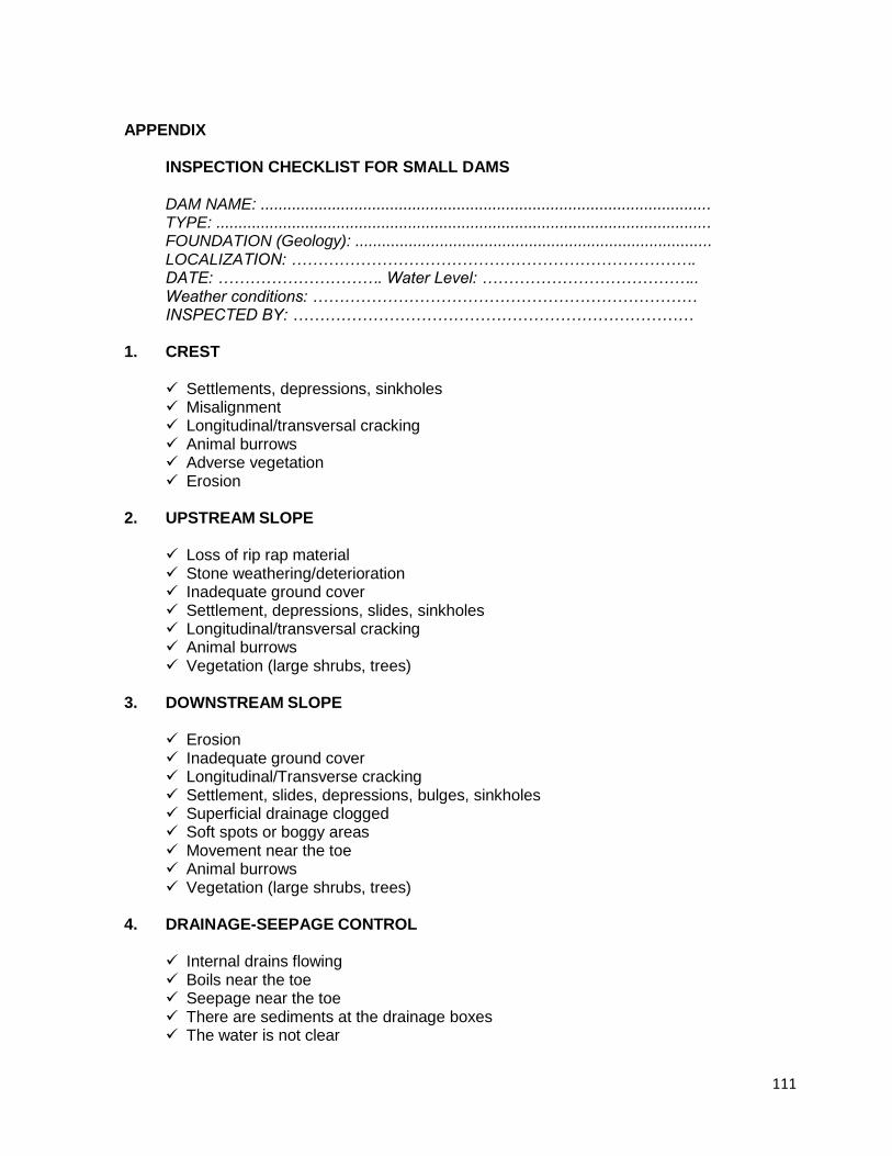
111
APPENDIX INSPECTION CHECKLIST FOR SMALL DAMS DAM NAME: ..................................................................................................... TYPE: ............................................................................................................... FOUNDATION (Geology): ................................................................................ LOCALIZATION: …………………………………………………………………. DATE: …………………………. Water Level: ………………………………….. Weather conditions: ……………………………………………………………… INSPECTED BY: …………………………………………………………………
1. CREST Settlements, depressions, sinkholes Misalignment Longitudinal/transversal cracking Animal burrows Adverse vegetation Erosion
2. UPSTREAM SLOPE Loss of rip rap material Stone weathering/deterioration Inadequate ground cover Settlement, depressions, slides, sinkholes Longitudinal/transversal cracking Animal burrows Vegetation (large shrubs, trees)
3. DOWNSTREAM SLOPE Erosion Inadequate ground cover Longitudinal/Transverse cracking Settlement, slides, depressions, bulges, sinkholes Superficial drainage clogged Soft spots or boggy areas Movement near the toe Animal burrows Vegetation (large shrubs, trees)
4. DRAINAGE-SEEPAGE CONTROL Internal drains flowing Boils near the toe Seepage near the toe There are sediments at the drainage boxes The water is not clear

112
5. ABUTMENTS AND CONTACTS WITH ABUTMENT Erosion Differential movement Cracks Settlement, slides, depressions, bulges, sinkholes Leakage water (seepage) Animal burrows Vegetation at the dam toe (large shrubs, trees)
6. APPROACHING CHANNEL Instability of the side channel Tilting of sidewalls Erosion or back cutting Sloughing Restriction by vegetation Obstruction with debris Log boom, condition or need Concrete lining deterioration, cracking or settlement
7. OUTLET WORKS – SPILLWAY, SPILLWAY’S CHUTE, STILLING BASING/POOL
Concrete surfaces show:
Spalling or scaling
Cracking
Erosion
Exposed reinforcement Energy dissipators show:
Sign of deterioration
Covered with debris
Sign of inadequacy
Obstruction Slab movement, heaving, settlement Wall movement, settlement, tilting Undermining foundation from plunge poll by erosion Poor hydraulic performance, hydraulic jump in bucket Excessive vibration
8. OUTLET WORKS – INLET STRUCTURES/CONDUIT
Seepage into structure Debris or obstruction Displaced floor slabs Poor hydraulic conditions, turbulence or vortices Vibrations, interference with flow Concrete surfaces show:
Spalling or scaling
Cracking
Erosion

113
Exposed reinforcement The conduit joints show:
Displacement or offset
Loss of joint material
Leakage Are the trash racks:
Broken or bent
Corroded or rusted
Obstructed Each of these deterioration possibilities need to be addressed in terms of: ( ) Not applicable ( ) No ( ) Yes ( ) Need to be monitored ( ) Need to be investigated ( ) Need to be repaired ( ) Need to be registered Observation: All important deteriorations need to be registered with one or more
photographs taken during the inspection.
114
7. REHABILITATION PRACTICES FOR SMALL DAMS 7.1 INTRODUCTION
Aging of embankment dams, updating of design standards and criteria and the
development of conditions affecting the safety of dams have resulted in a need for re-evaluation and, in some instances rehabilitation of dams.
The shortcomings are identified during the execution of safety inspections discussed in
the previous section. Even if finance is not readily available, rehabilitation or improvement is necessary to
protect the asset of the owner of the dam, but also to protect the owner against claims caused by dam breaches.
In this section techniques are presented for rehabilitation of embankment dams.
7.2 TECHNIQUES FOR IMPROVING SPILLWAY SAFETY 7.2.1 Introduction
A 1981 survey of non-Federal dams in the United States, concluded that 81 % had dam safety shortcomings because their spillways were not adequate to pass the estimated maximum design floods. This often reflects the difference between present-day design flood and the criteria in vogue at the time the dams were constructed.
Embankment dams are particularly sensitive to failure caused by overtopping, both
during construction and while in service. Overtopping of a dam often causes dam failures. National statistics show that overtopping due to inadequate spillway design, debris blockage of spillway, or settlement of the dam embankment crests account for approximately 34 % of all U.S. dam failures. Embankments compacted to Standard Proctor density standards provide an elastic structure and show less cracking problems – often embankment dams are not compacted to this standard. Dam owners sometimes raise the spillway structures temporarily with say sandbags or definitely with concrete without realizing the effect on the safety of the structure.
In South West of France, a survey of small embankment dams has been carried out in
1997-1999 on more than 200 dam less than 20 m high [Lautrin, 2003]. 43 % of the spillways of those dams have been raised, ranging from 0,1 to 1,2 m and thereby reducing significantly the spillway capacity. The raising is obtained by means of a wooden beam (theoretically removable) or by means of a concrete beam.
The most frequent type of spillway used with small embankment dams, in South Africa,
is a spillway cut from one of the banks of the river. Usually the material excavated is used for the fill in the embankment. This type of spillway is known as a by-wash spillway. A spillway can be located in a saddle adjacent to the reservoir if located at the proposed full supply level.
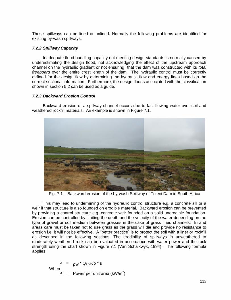
115
These spillways can be lined or unlined. Normally the following problems are identified for existing by-wash spillways.
7.2.2 Spillway Capacity
Inadequate flood handling capacity not meeting design standards is normally caused by
underestimating the design flood, not acknowledging the effect of the upstream approach channel on the hydraulic gradient or not ensuring that the dam was constructed with its total freeboard over the entire crest length of the dam. The hydraulic control must be correctly defined for the design flow by determining the hydraulic flow and energy lines based on the correct sectional information. Furthermore, the design floods associated with the classification shown in section 5.2 can be used as a guide. 7.2.3 Backward Erosion Control
Backward erosion of a spillway channel occurs due to fast flowing water over soil and
weathered rockfill materials. An example is shown in Figure 7.1.
Fig. 7.1 – Backward erosion of the by-wash Spillway of Toleni Dam in South Africa
This may lead to undermining of the hydraulic control structure e.g. a concrete sill or a
weir if that structure is also founded on erodible material. Backward erosion can be prevented by providing a control structure e.g. concrete weir founded on a solid unerodible foundation. Erosion can be controlled by limiting the depth and the velocity of the water depending on the type of gravel or soil medium between grasses in the case of grass lined channels. In arid areas care must be taken not to use grass as the grass will die and provide no resistance to erosion i.e. it will not be effective. A “better practice” is to protect the soil with a liner or rockfill as described in the following sections. The erodibility of spillways in unweathered to moderately weathered rock can be evaluated in accordance with water power and the rock strength using the chart shown in Figure 7.1 (Van Schalkwyk, 1994). The following formula applies:
P = ρw * Q1:100/b * s
Where P = Power per unit area (kW/m2)
116
ρw = Density of water in kg/m3
Q = Discharge in m3/s b = Width of channel in m s = Slope of channel (m/m)
7.2.4 Spillway Chute or Spillway Return Channel Alignment
Change of direction in the spillway chute or spillway return channel during supercritical
flow conditions provides problems regarding erosion of materials. Water in supercritical flow does not change direction and tends to carry on straight except if the floor is elevated correctly. Straight chutes for supercritical flow conditions must be provided. 7.2.5 Deformation of Spillway Structures Provided Over Embankments
It is possible to construct the spillway over the embankment, with two conditions:
Expected settlement of the foundation must be very low or must occur mostly during construction of the original embankment (short-term settlement).
Expected settlement of the original embankment must be very low, that means good compaction of the material.
A concrete spillway constructed over an earthfill embankment on soft foundations will
therefore settle with movement of the concrete panels. Failure may be caused due to ingress of overflowing water and uplift of concrete panels. Although often expensive, (or costly) minimum risks and best solutions for the improvement of spillways include the “tried and tested” approach of location of spillways on solid foundations.
Nevertheless, construction of an additional spillway over the embankment of an existing
dam may be a solution to consider, as settlement has often ceased after some decades.
7.2.6 Erosion of the Abutment Wall Between the Embankment and the Spillway The solution recommended for the transition between the embankment and the spillway
is a concrete wall i.e. mass gravity or cantilever (depending on foundation, height and economics).
If the protection of an earthfill abutment (or the training wall of one side of a spillway
return channel) comprises a layer (or layers) of rock (or rip-rap), it may be damaged (or washed away) after cracking of soil and erosion by storm water or high powered flowing water. Materials used for this type of erosion protection must be carefully designed to accommodate the unit power of the flowing water. The protection must also be designed to accommodate the safety evaluation check discharge.
7.2.7 Gabions Used as Sill in by-pass Channels
Gabion baskets must be considered with care as they have shortcomings:
Very often the galvanized steel wire that makes up the rectangular (or square) panels of the baskets corrodes and results in individual stones in the baskets being exposed to
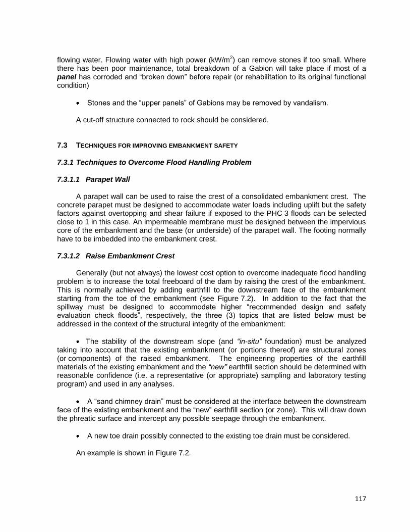
117
flowing water. Flowing water with high power (kW/m2) can remove stones if too small. Where there has been poor maintenance, total breakdown of a Gabion will take place if most of a panel has corroded and “broken down” before repair (or rehabilitation to its original functional condition)
Stones and the “upper panels” of Gabions may be removed by vandalism. A cut-off structure connected to rock should be considered.
7.3 TECHNIQUES FOR IMPROVING EMBANKMENT SAFETY
7.3.1 Techniques to Overcome Flood Handling Problem 7.3.1.1 Parapet Wall
A parapet wall can be used to raise the crest of a consolidated embankment crest. The
concrete parapet must be designed to accommodate water loads including uplift but the safety factors against overtopping and shear failure if exposed to the PHC 3 floods can be selected close to 1 in this case. An impermeable membrane must be designed between the impervious core of the embankment and the base (or underside) of the parapet wall. The footing normally have to be imbedded into the embankment crest.
7.3.1.2 Raise Embankment Crest
Generally (but not always) the lowest cost option to overcome inadequate flood handling
problem is to increase the total freeboard of the dam by raising the crest of the embankment. This is normally achieved by adding earthfill to the downstream face of the embankment starting from the toe of the embankment (see Figure 7.2). In addition to the fact that the spillway must be designed to accommodate higher “recommended design and safety evaluation check floods”, respectively, the three (3) topics that are listed below must be addressed in the context of the structural integrity of the embankment:
The stability of the downstream slope (and “in-situ” foundation) must be analyzed taking into account that the existing embankment (or portions thereof) are structural zones (or components) of the raised embankment. The engineering properties of the earthfill materials of the existing embankment and the “new” earthfill section should be determined with reasonable confidence (i.e. a representative (or appropriate) sampling and laboratory testing program) and used in any analyses.
A “sand chimney drain” must be considered at the interface between the downstream face of the existing embankment and the “new” earthfill section (or zone). This will draw down the phreatic surface and intercept any possible seepage through the embankment.
A new toe drain possibly connected to the existing toe drain must be considered. An example is shown in Figure 7.2.
118
Fig. 7.2 – Section through an embankment showing rehabilitation with a positive effect
both on stability, piping control and seepage control
Furthermore, to extend an earthfill core a High Density Polyethylene Sheet may be used to raise the core by anchoring it in a trench excavated in the top of the core. This method is especially applicable where ice conditions occur where the top of the core can be damaged by low temperatures.
7.3.1.3 Protection of Embankment from Erosion During Overtopping Erosion as a result of overflow during flood events is a principal cause of embankment
dam failure. Consequently, the approach to solving this problem has been not to allow overtopping. Preventing overtopping of existing dams to accommodate today’s current estimates of inflow floods often requires costly modifications to the spillway or raising of the embankment. For a large number of potentially unsafe dams with inadequate spillway capacity, permitting overtopping during large or infrequent floods would result in significant benefits.
If overtopping of an embankment is allowed, the owner of the dam must ensure that the
downstream slope is sufficiently protected to prevent erosion. Two erosion protection systems i.e. articulated concrete blocks (ACB) and roller compacted concrete (RCC) are often used successfully for the protection of the downstream face of embankments during floods.
(a) Articulated Concrete Blocks
An auxiliary spillway constructed with small cable tied concrete blocks system laid on a
geotextile base is capable of withstanding velocities less than 8 m/s and provides a low cost alternative to reinforced concrete, as can be seen in Figure 7.3 and 7.4. Care should be taken to design for lower velocities of up to maximum 5 m/s (say) to accommodate deteriorating (or ageing) conditions during the life of the dam.
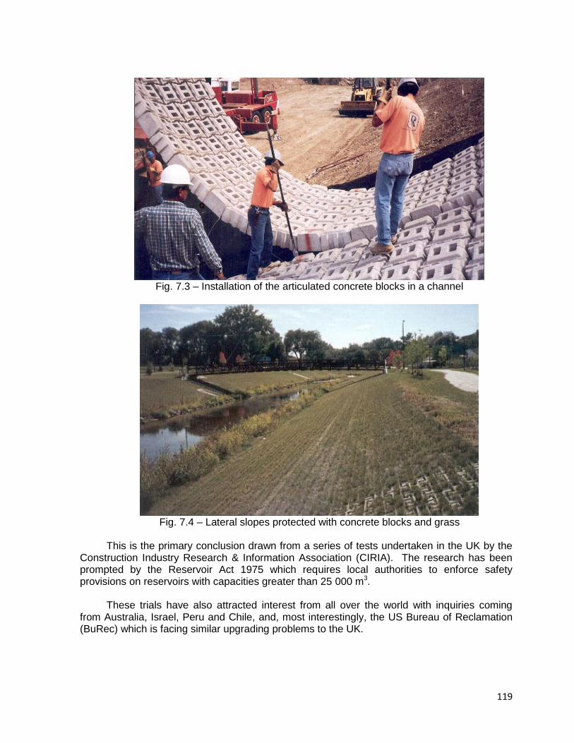
119
Fig. 7.3 – Installation of the articulated concrete blocks in a channel
Fig. 7.4 – Lateral slopes protected with concrete blocks and grass
This is the primary conclusion drawn from a series of tests undertaken in the UK by the
Construction Industry Research & Information Association (CIRIA). The research has been prompted by the Reservoir Act 1975 which requires local authorities to enforce safety provisions on reservoirs with capacities greater than 25 000 m3.
These trials have also attracted interest from all over the world with inquiries coming
from Australia, Israel, Peru and Chile, and, most interestingly, the US Bureau of Reclamation (BuRec) which is facing similar upgrading problems to the UK.
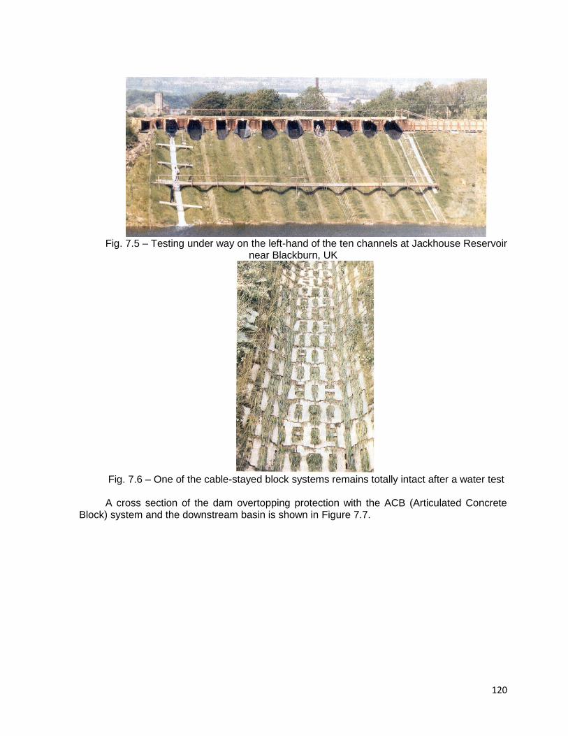
120
Fig. 7.5 – Testing under way on the left-hand of the ten channels at Jackhouse Reservoir
near Blackburn, UK
Fig. 7.6 – One of the cable-stayed block systems remains totally intact after a water test A cross section of the dam overtopping protection with the ACB (Articulated Concrete
Block) system and the downstream basin is shown in Figure 7.7.
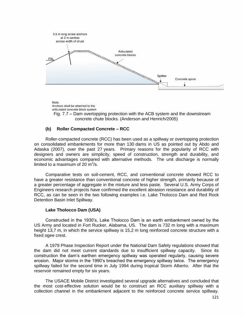
121
Fig. 7.7 – Dam overtopping protection with the ACB system and the downstream
concrete chute blocks. (Anderson and Henrich/2005) (b) Roller Compacted Concrete – RCC
Roller-compacted concrete (RCC) has been used as a spillway or overtopping protection
on consolidated embankments for more than 130 dams in US as pointed out by Abdo and Adaska (2007), over the past 27 years. Primary reasons for the popularity of RCC with designers and owners are simplicity, speed of construction, strength and durability, and economic advantages compared with alternative methods. The unit discharge is normally limited to a maximum of 20 m2/s.
Comparative tests on soil-cement, RCC, and conventional concrete showed RCC to
have a greater resistance than conventional concrete of higher strength, primarily because of a greater percentage of aggregate in the mixture and less paste. Several U.S. Army Corps of Engineers research projects have confirmed the excellent abrasion resistance and durability of RCC, as can be seen in the two following examples i.e. Lake Tholocco Dam and Red Rock Detention Basin Inlet Spillway.
Lake Tholocco Dam (USA) Constructed in the 1930’s, Lake Tholocco Dam is an earth embankment owned by the
US Army and located in Fort Rucker, Alabama, US. The dam is 732 m long with a maximum height 13,7 m, in which the service spillway is 15,2 m long reinforced concrete structure with a fixed ogee crest.
A 1979 Phase Inspection Report under the National Dam Safety regulations showed that
the dam did not meet current standards due to insufficient spillway capacity. Since its construction the dam’s earthen emergency spillway was operated regularly, causing severe erosion. Major storms in the 1990’s breached the emergency spillway twice. The emergency spillway failed for the second time in July 1994 during tropical Storm Alberto. After that the reservoir remained empty for six years.
The USACE Mobile District investigated several upgrade alternatives and concluded that
the most cost-effective solution would be to construct an RCC auxiliary spillway with a collection channel in the embankment adjacent to the reinforced concrete service spillway.
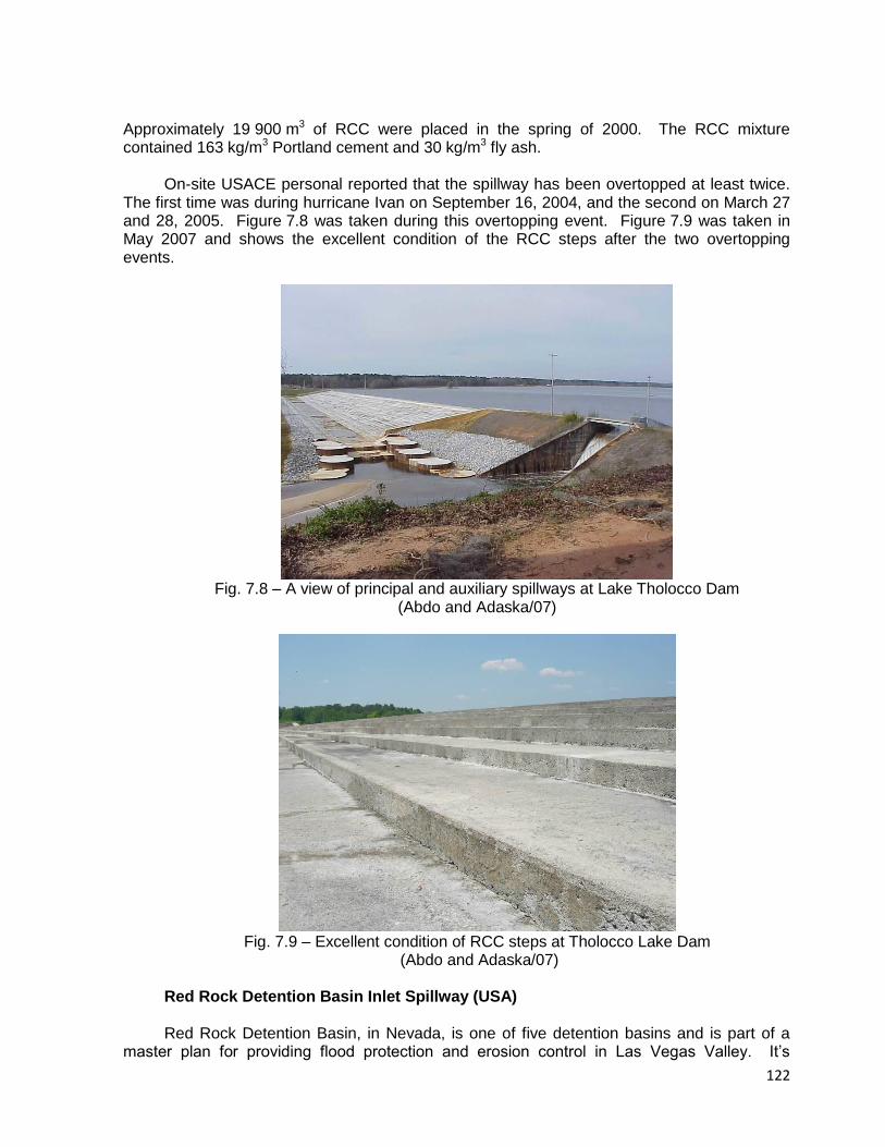
122
Approximately 19 900 m3 of RCC were placed in the spring of 2000. The RCC mixture contained 163 kg/m3 Portland cement and 30 kg/m3 fly ash.
On-site USACE personal reported that the spillway has been overtopped at least twice.
The first time was during hurricane Ivan on September 16, 2004, and the second on March 27 and 28, 2005. Figure 7.8 was taken during this overtopping event. Figure 7.9 was taken in May 2007 and shows the excellent condition of the RCC steps after the two overtopping events.
Fig. 7.8 – A view of principal and auxiliary spillways at Lake Tholocco Dam
(Abdo and Adaska/07)
Fig. 7.9 – Excellent condition of RCC steps at Tholocco Lake Dam
(Abdo and Adaska/07)
Red Rock Detention Basin Inlet Spillway (USA) Red Rock Detention Basin, in Nevada, is one of five detention basins and is part of a
master plan for providing flood protection and erosion control in Las Vegas Valley. It’s
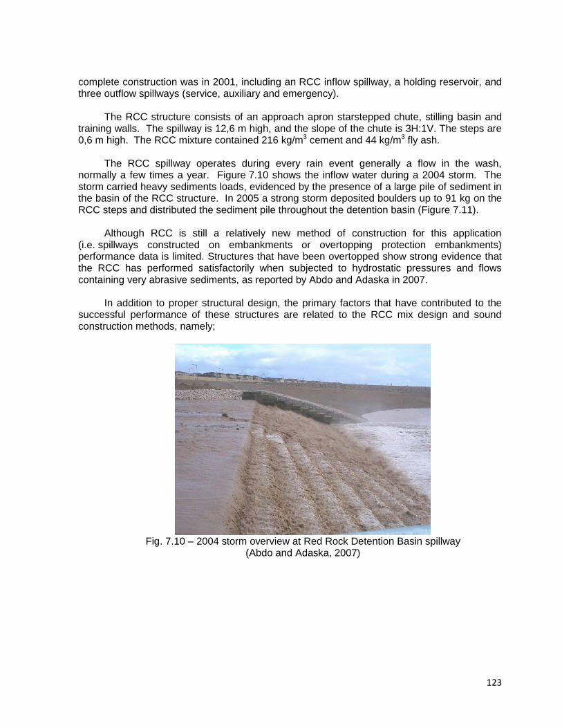
123
complete construction was in 2001, including an RCC inflow spillway, a holding reservoir, and three outflow spillways (service, auxiliary and emergency).
The RCC structure consists of an approach apron starstepped chute, stilling basin and
training walls. The spillway is 12,6 m high, and the slope of the chute is 3H:1V. The steps are 0,6 m high. The RCC mixture contained 216 kg/m3 cement and 44 kg/m3 fly ash.
The RCC spillway operates during every rain event generally a flow in the wash,
normally a few times a year. Figure 7.10 shows the inflow water during a 2004 storm. The storm carried heavy sediments loads, evidenced by the presence of a large pile of sediment in the basin of the RCC structure. In 2005 a strong storm deposited boulders up to 91 kg on the RCC steps and distributed the sediment pile throughout the detention basin (Figure 7.11).
Although RCC is still a relatively new method of construction for this application
(i.e. spillways constructed on embankments or overtopping protection embankments) performance data is limited. Structures that have been overtopped show strong evidence that the RCC has performed satisfactorily when subjected to hydrostatic pressures and flows containing very abrasive sediments, as reported by Abdo and Adaska in 2007.
In addition to proper structural design, the primary factors that have contributed to the
successful performance of these structures are related to the RCC mix design and sound construction methods, namely;
Fig. 7.10 – 2004 storm overview at Red Rock Detention Basin spillway
(Abdo and Adaska, 2007)
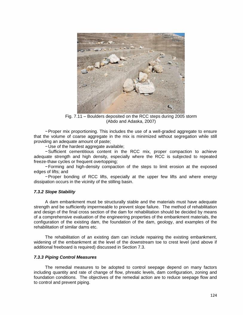
124
Fig. 7.11 – Boulders deposited on the RCC steps during 2005 storm
(Abdo and Adaska, 2007)
− Proper mix proportioning. This includes the use of a well-graded aggregate to ensure that the volume of coarse aggregate in the mix is minimized without segregation while still providing an adequate amount of paste;
− Use of the hardest aggregate available; − Sufficient cementitious content in the RCC mix, proper compaction to achieve
adequate strength and high density, especially where the RCC is subjected to repeated freeze-thaw cycles or frequent overtopping;
− Forming and high-density compaction of the steps to limit erosion at the exposed edges of lifts; and
− Proper bonding of RCC lifts, especially at the upper few lifts and where energy dissipation occurs in the vicinity of the stilling basin. 7.3.2 Slope Stability
A dam embankment must be structurally stable and the materials must have adequate
strength and be sufficiently impermeable to prevent slope failure. The method of rehabilitation and design of the final cross section of the dam for rehabilitation should be decided by means of a comprehensive evaluation of the engineering properties of the embankment materials, the configuration of the existing dam, the foundation of the dam, geology, and examples of the rehabilitation of similar dams etc.
The rehabilitation of an existing dam can include repairing the existing embankment,
widening of the embankment at the level of the downstream toe to crest level (and above if additional freeboard is required) discussed in Section 7.3.
7.3.3 Piping Control Measures
The remedial measures to be adopted to control seepage depend on many factors
including quantity and rate of change of flow, phreatic levels, dam configuration, zoning and foundation conditions. The objectives of the remedial action are to reduce seepage flow and to control and prevent piping.
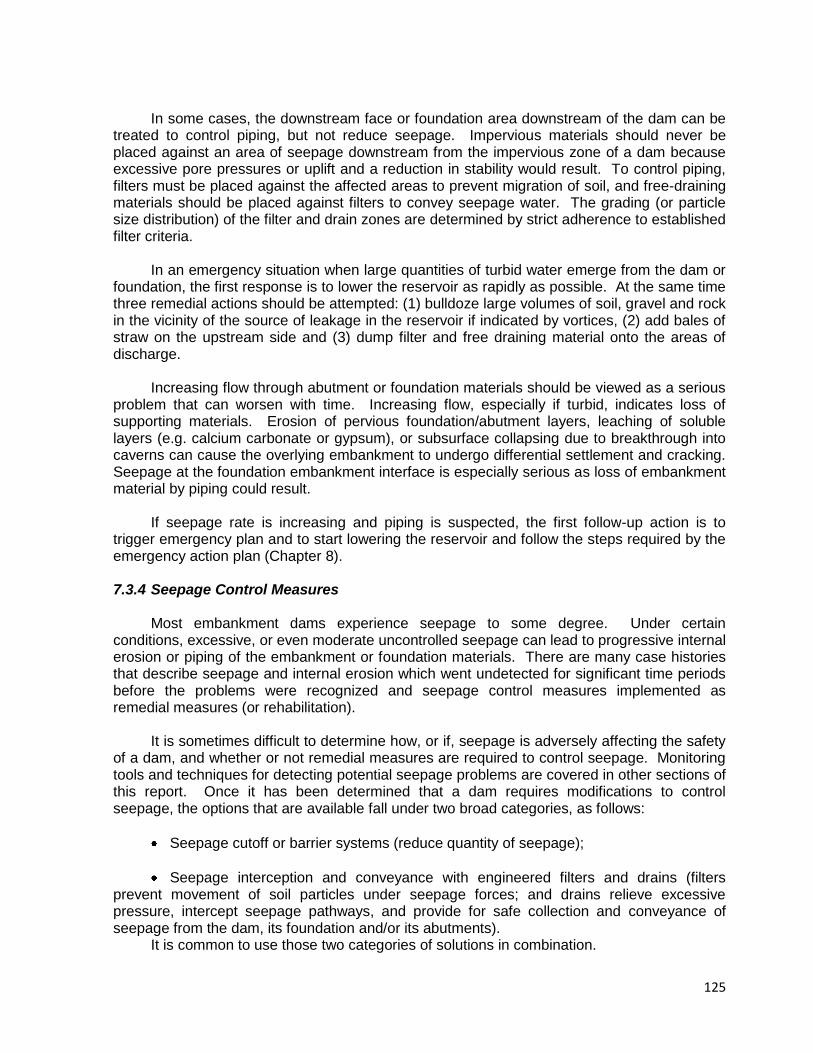
125
In some cases, the downstream face or foundation area downstream of the dam can be treated to control piping, but not reduce seepage. Impervious materials should never be placed against an area of seepage downstream from the impervious zone of a dam because excessive pore pressures or uplift and a reduction in stability would result. To control piping, filters must be placed against the affected areas to prevent migration of soil, and free-draining materials should be placed against filters to convey seepage water. The grading (or particle size distribution) of the filter and drain zones are determined by strict adherence to established filter criteria.
In an emergency situation when large quantities of turbid water emerge from the dam or
foundation, the first response is to lower the reservoir as rapidly as possible. At the same time three remedial actions should be attempted: (1) bulldoze large volumes of soil, gravel and rock in the vicinity of the source of leakage in the reservoir if indicated by vortices, (2) add bales of straw on the upstream side and (3) dump filter and free draining material onto the areas of discharge.
Increasing flow through abutment or foundation materials should be viewed as a serious
problem that can worsen with time. Increasing flow, especially if turbid, indicates loss of supporting materials. Erosion of pervious foundation/abutment layers, leaching of soluble layers (e.g. calcium carbonate or gypsum), or subsurface collapsing due to breakthrough into caverns can cause the overlying embankment to undergo differential settlement and cracking. Seepage at the foundation embankment interface is especially serious as loss of embankment material by piping could result.
If seepage rate is increasing and piping is suspected, the first follow-up action is to
trigger emergency plan and to start lowering the reservoir and follow the steps required by the emergency action plan (Chapter 8). 7.3.4 Seepage Control Measures
Most embankment dams experience seepage to some degree. Under certain conditions, excessive, or even moderate uncontrolled seepage can lead to progressive internal erosion or piping of the embankment or foundation materials. There are many case histories that describe seepage and internal erosion which went undetected for significant time periods before the problems were recognized and seepage control measures implemented as remedial measures (or rehabilitation).
It is sometimes difficult to determine how, or if, seepage is adversely affecting the safety
of a dam, and whether or not remedial measures are required to control seepage. Monitoring tools and techniques for detecting potential seepage problems are covered in other sections of this report. Once it has been determined that a dam requires modifications to control seepage, the options that are available fall under two broad categories, as follows:
Seepage cutoff or barrier systems (reduce quantity of seepage);
Seepage interception and conveyance with engineered filters and drains (filters prevent movement of soil particles under seepage forces; and drains relieve excessive pressure, intercept seepage pathways, and provide for safe collection and conveyance of seepage from the dam, its foundation and/or its abutments).
It is common to use those two categories of solutions in combination.

126
7.3.4.1 Seepage Barriers and Cutoff Systems
This section provides a brief overview of commonly used seepage control systems. Seepage cutoffs and barriers are intended to reduce the amount of seepage and
minimize downstream pressures and exit gradients. Depending on the site and foundation conditions, seepage cutoff systems may provide either:
Positive cutoff that completely penetrates pervious zones and ties into impervious soil layers or bedrock in the dam foundation and abutments, or
− Partial cutoff, which is sometimes used for deep pervious foundations to lengthen the
seepage path and reduce exit gradients to acceptable levels. There are many different types of cutoff systems that are used for dam rehabilitation.
The primary objective is to provide a low permeability element within the dam and/or its foundation, either as the primary seepage barrier or to supplement existing barriers. Cutoffs may be classified according to their stiffness, the type of materials used, or construction methods used.
The terms cutoff “wall” or “diaphragm” are often used to distinguish seepage barriers that
are thin compared to the surrounding embankment. Barriers employed for dam rehabilitation may be constructed through the dam and foundation from the existing dam crest (diaphragm or wall).
Alternatively barriers may be constructed using a liner system on the upstream face of
the dam in combination with vertical or horizontal seepage barriers extending from the upstream toe.
Some of the seepage barriers that are commonly used for dam rehabilitation are listed in
Table 7.1 .Most of those solutions require lowering of the reservoir level significantly, in order to reduce hydraulic gradients during rehabilitation and the risk of wash-out of cement and bentonite. In case of construction of rehabilitation works on the upstream face of the dam, the reservoir must be emptied.
Table 7.1 – Common Seepage cut-off measures identified for Alluvium and Earthfill
Foundations of small dams
Type of cutoff Method Materials used Remarks and
References
Core trench:
Open trench is excavated and, if stable, filling with one of the materials is done
Earthfill Soil-bentonite Concrete-bentonite
Depth limited to some metres
Slurry trench: Slurry wall, concrete wall,
tremmy
Open trench by extended backhoe, kept open and stabilized with bentonite slurry
Concrete by tremmy pipe. Primary and secondary panels are inserted once sufficient strength has been identified
Figure 7.4 and Figure 7.9 and 7.10
Sheet piles curtain Inserted by vibratory Steel Curtain not taken to
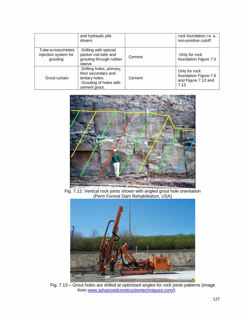
127
and hydraulic pile drivers
rock foundation i.e. a non-positive cutoff.
Tube-a-manchettes injection system for
grouting
Drilling with special packer rod tube and grouting through rubber sleeve
Cement Only for rock
foundation Figure 7.5
Grout curtain
Drilling holes, primary, then secondary and tertiary holes. Grouting of holes with
cement grout.
Cement
Only for rock foundation Figure 7.6 and Figure 7.12 and 7.13
Fig. 7.12: Vertical rock joints shown with angled grout hole orientation
(Penn Forrest Dam Rehabilitation, USA)
Fig. 7.13 – Grout holes are drilled at optimized angles for rock joints patterns (image
from www.advancedconstructiontechniques.com/).
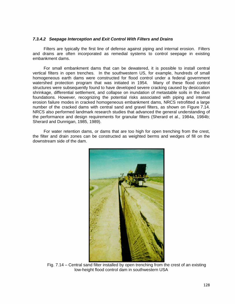
128
7.3.4.2 Seepage Interception and Exit Control With Filters and Drains
Filters are typically the first line of defense against piping and internal erosion. Filters
and drains are often incorporated as remedial systems to control seepage in existing embankment dams.
For small embankment dams that can be dewatered, it is possible to install central
vertical filters in open trenches. In the southwestern US, for example, hundreds of small homogeneous earth dams were constructed for flood control under a federal government watershed protection program that was initiated in 1954. Many of these flood control structures were subsequently found to have developed severe cracking caused by desiccation shrinkage, differential settlement, and collapse on inundation of metastable soils in the dam foundations. However, recognizing the potential risks associated with piping and internal erosion failure modes in cracked homogeneous embankment dams, NRCS retrofitted a large number of the cracked dams with central sand and gravel filters, as shown on Figure 7.14. NRCS also performed landmark research studies that advanced the general understanding of the performance and design requirements for granular filters (Sherard et al., 1984a, 1984b; Sherard and Dunnigan, 1985, 1989).
For water retention dams, or dams that are too high for open trenching from the crest,
the filter and drain zones can be constructed as weighted berms and wedges of fill on the downstream side of the dam.
Fig. 7.14 – Central sand filter installed by open trenching from the crest of an existing
low-height flood control dam in southwestern USA
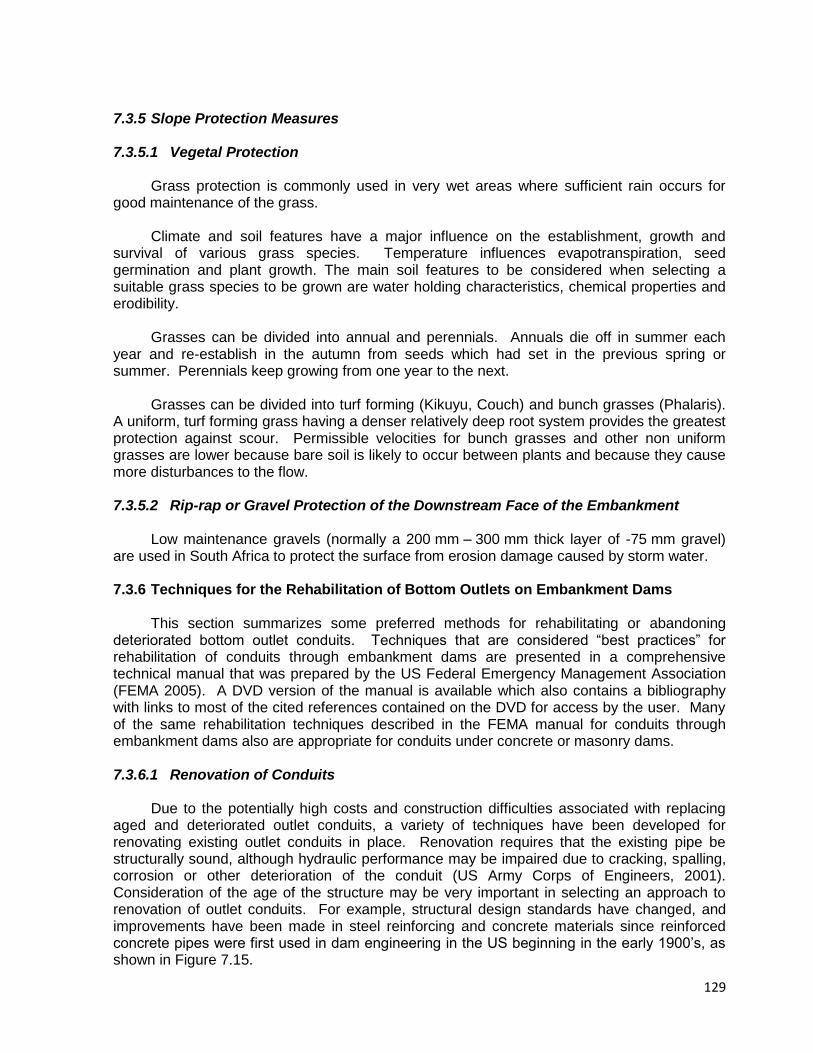
129
7.3.5 Slope Protection Measures 7.3.5.1 Vegetal Protection
Grass protection is commonly used in very wet areas where sufficient rain occurs for
good maintenance of the grass. Climate and soil features have a major influence on the establishment, growth and
survival of various grass species. Temperature influences evapotranspiration, seed germination and plant growth. The main soil features to be considered when selecting a suitable grass species to be grown are water holding characteristics, chemical properties and erodibility.
Grasses can be divided into annual and perennials. Annuals die off in summer each
year and re-establish in the autumn from seeds which had set in the previous spring or summer. Perennials keep growing from one year to the next.
Grasses can be divided into turf forming (Kikuyu, Couch) and bunch grasses (Phalaris).
A uniform, turf forming grass having a denser relatively deep root system provides the greatest protection against scour. Permissible velocities for bunch grasses and other non uniform grasses are lower because bare soil is likely to occur between plants and because they cause more disturbances to the flow.
7.3.5.2 Rip-rap or Gravel Protection of the Downstream Face of the Embankment
Low maintenance gravels (normally a 200 mm – 300 mm thick layer of -75 mm gravel)
are used in South Africa to protect the surface from erosion damage caused by storm water.
7.3.6 Techniques for the Rehabilitation of Bottom Outlets on Embankment Dams This section summarizes some preferred methods for rehabilitating or abandoning
deteriorated bottom outlet conduits. Techniques that are considered “best practices” for rehabilitation of conduits through embankment dams are presented in a comprehensive technical manual that was prepared by the US Federal Emergency Management Association (FEMA 2005). A DVD version of the manual is available which also contains a bibliography with links to most of the cited references contained on the DVD for access by the user. Many of the same rehabilitation techniques described in the FEMA manual for conduits through embankment dams also are appropriate for conduits under concrete or masonry dams.
7.3.6.1 Renovation of Conduits
Due to the potentially high costs and construction difficulties associated with replacing
aged and deteriorated outlet conduits, a variety of techniques have been developed for renovating existing outlet conduits in place. Renovation requires that the existing pipe be structurally sound, although hydraulic performance may be impaired due to cracking, spalling, corrosion or other deterioration of the conduit (US Army Corps of Engineers, 2001). Consideration of the age of the structure may be very important in selecting an approach to renovation of outlet conduits. For example, structural design standards have changed, and improvements have been made in steel reinforcing and concrete materials since reinforced concrete pipes were first used in dam engineering in the US beginning in the early 1900’s, as shown in Figure 7.15.
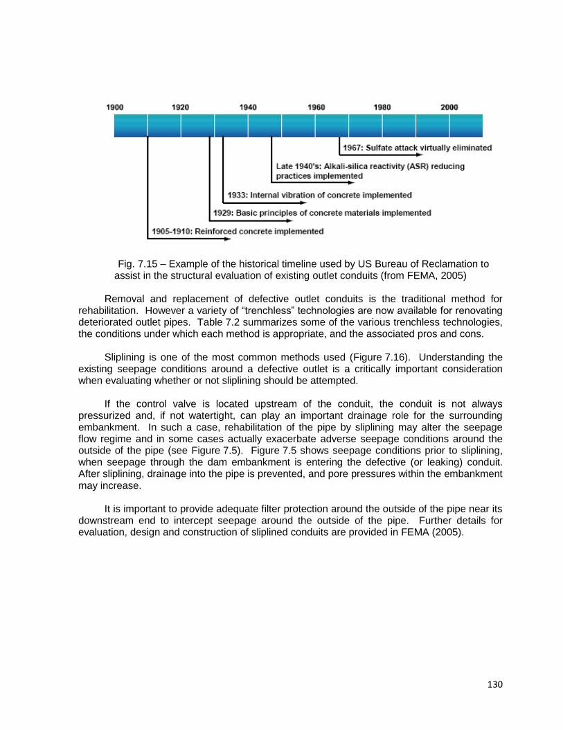
130
Fig. 7.15 – Example of the historical timeline used by US Bureau of Reclamation to assist in the structural evaluation of existing outlet conduits (from FEMA, 2005)
Removal and replacement of defective outlet conduits is the traditional method for
rehabilitation. However a variety of “trenchless” technologies are now available for renovating deteriorated outlet pipes. Table 7.2 summarizes some of the various trenchless technologies, the conditions under which each method is appropriate, and the associated pros and cons.
Sliplining is one of the most common methods used (Figure 7.16). Understanding the
existing seepage conditions around a defective outlet is a critically important consideration when evaluating whether or not sliplining should be attempted.
If the control valve is located upstream of the conduit, the conduit is not always
pressurized and, if not watertight, can play an important drainage role for the surrounding embankment. In such a case, rehabilitation of the pipe by sliplining may alter the seepage flow regime and in some cases actually exacerbate adverse seepage conditions around the outside of the pipe (see Figure 7.5). Figure 7.5 shows seepage conditions prior to sliplining, when seepage through the dam embankment is entering the defective (or leaking) conduit. After sliplining, drainage into the pipe is prevented, and pore pressures within the embankment may increase.
It is important to provide adequate filter protection around the outside of the pipe near its
downstream end to intercept seepage around the outside of the pipe. Further details for evaluation, design and construction of sliplined conduits are provided in FEMA (2005).
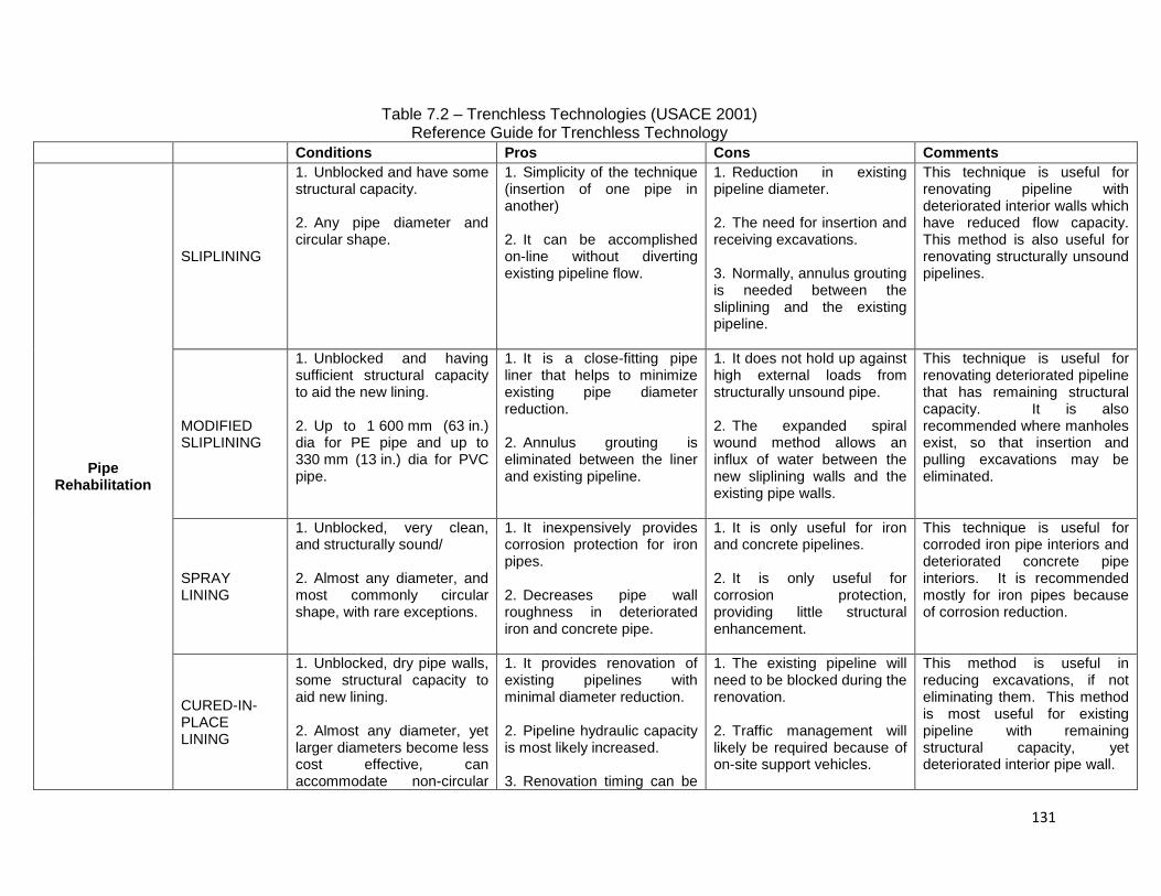
131
Table 7.2 – Trenchless Technologies (USACE 2001) Reference Guide for Trenchless Technology
Conditions Pros Cons Comments
Pipe Rehabilitation
SLIPLINING
1. Unblocked and have some structural capacity. 2. Any pipe diameter and circular shape.
1. Simplicity of the technique (insertion of one pipe in another) 2. It can be accomplished on-line without diverting existing pipeline flow.
1. Reduction in existing pipeline diameter. 2. The need for insertion and receiving excavations. 3. Normally, annulus grouting is needed between the sliplining and the existing pipeline.
This technique is useful for renovating pipeline with deteriorated interior walls which have reduced flow capacity. This method is also useful for renovating structurally unsound pipelines.
MODIFIED SLIPLINING
1. Unblocked and having sufficient structural capacity to aid the new lining. 2. Up to 1 600 mm (63 in.) dia for PE pipe and up to 330 mm (13 in.) dia for PVC pipe.
1. It is a close-fitting pipe liner that helps to minimize existing pipe diameter reduction. 2. Annulus grouting is eliminated between the liner and existing pipeline.
1. It does not hold up against high external loads from structurally unsound pipe. 2. The expanded spiral wound method allows an influx of water between the new sliplining walls and the existing pipe walls.
This technique is useful for renovating deteriorated pipeline that has remaining structural capacity. It is also recommended where manholes exist, so that insertion and pulling excavations may be eliminated.
SPRAY LINING
1. Unblocked, very clean, and structurally sound/ 2. Almost any diameter, and most commonly circular shape, with rare exceptions.
1. It inexpensively provides corrosion protection for iron pipes. 2. Decreases pipe wall roughness in deteriorated iron and concrete pipe.
1. It is only useful for iron and concrete pipelines. 2. It is only useful for corrosion protection, providing little structural enhancement.
This technique is useful for corroded iron pipe interiors and deteriorated concrete pipe interiors. It is recommended mostly for iron pipes because of corrosion reduction.
CURED-IN-PLACE LINING
1. Unblocked, dry pipe walls, some structural capacity to aid new lining. 2. Almost any diameter, yet larger diameters become less cost effective, can accommodate non-circular
1. It provides renovation of existing pipelines with minimal diameter reduction. 2. Pipeline hydraulic capacity is most likely increased. 3. Renovation timing can be
1. The existing pipeline will need to be blocked during the renovation. 2. Traffic management will likely be required because of on-site support vehicles.
This method is useful in reducing excavations, if not eliminating them. This method is most useful for existing pipeline with remaining structural capacity, yet deteriorated interior pipe wall.
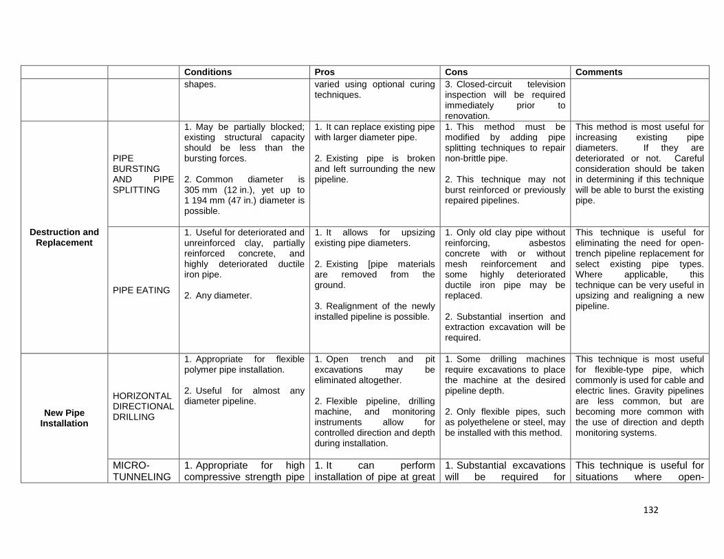
132
Conditions Pros Cons Comments
shapes.
varied using optional curing techniques.
3. Closed-circuit television inspection will be required immediately prior to renovation.
Destruction and Replacement
PIPE BURSTING AND PIPE SPLITTING
1. May be partially blocked; existing structural capacity should be less than the bursting forces. 2. Common diameter is 305 mm (12 in.), yet up to 1 194 mm (47 in.) diameter is possible.
1. It can replace existing pipe with larger diameter pipe. 2. Existing pipe is broken and left surrounding the new pipeline.
1. This method must be modified by adding pipe splitting techniques to repair non-brittle pipe. 2. This technique may not burst reinforced or previously repaired pipelines.
This method is most useful for increasing existing pipe diameters. If they are deteriorated or not. Careful consideration should be taken in determining if this technique will be able to burst the existing pipe.
PIPE EATING
1. Useful for deteriorated and unreinforced clay, partially reinforced concrete, and highly deteriorated ductile iron pipe. 2. Any diameter.
1. It allows for upsizing existing pipe diameters. 2. Existing [pipe materials are removed from the ground. 3. Realignment of the newly installed pipeline is possible.
1. Only old clay pipe without reinforcing, asbestos concrete with or without mesh reinforcement and some highly deteriorated ductile iron pipe may be replaced. 2. Substantial insertion and extraction excavation will be required.
This technique is useful for eliminating the need for open-trench pipeline replacement for select existing pipe types. Where applicable, this technique can be very useful in upsizing and realigning a new pipeline.
New Pipe Installation
HORIZONTAL DIRECTIONAL DRILLING
1. Appropriate for flexible polymer pipe installation. 2. Useful for almost any diameter pipeline.
1. Open trench and pit excavations may be eliminated altogether. 2. Flexible pipeline, drilling machine, and monitoring instruments allow for controlled direction and depth during installation.
1. Some drilling machines require excavations to place the machine at the desired pipeline depth. 2. Only flexible pipes, such as polyethelene or steel, may be installed with this method.
This technique is most useful for flexible-type pipe, which commonly is used for cable and electric lines. Gravity pipelines are less common, but are becoming more common with the use of direction and depth monitoring systems.
MICRO-TUNNELING
1. Appropriate for high compressive strength pipe
1. It can perform installation of pipe at great
1. Substantial excavations will be required for
This technique is useful for situations where open-

133
Conditions Pros Cons Comments
types only, such as clay, reinforced fiberglass, and concrete pipes. 2. Useful for any diameter, 152 mm (6 in.) or greater.
depths and tunnel through various soils and rock sizes. 2. Gradient and alignment of newly installed pipe is precisely controlled.
insertion and extraction of the micro-tunneling machine. 2. Unexpected ground conditions can lead to a blocked machine, requiring an expensive removal.
trench installation of pipe is not economical or possible. Also, it is very useful for installation of gravity pipelines that require strict control of gradient and direction.
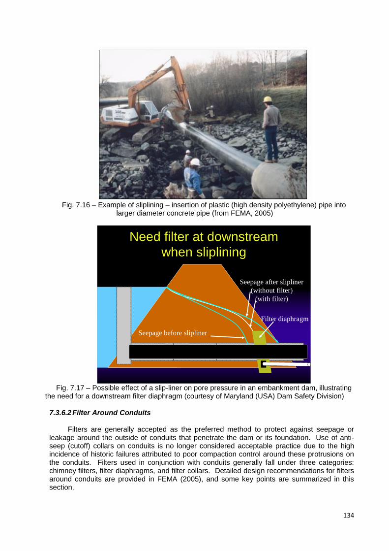
134
Fig. 7.16 – Example of sliplining – insertion of plastic (high density polyethylene) pipe into
larger diameter concrete pipe (from FEMA, 2005)
Need filter at downstream
when sliplining
Seepage before slipliner
Seepage after slipliner
(without filter)
(with filter)
Filter diaphragm
Fig. 7.17 – Possible effect of a slip-liner on pore pressure in an embankment dam, illustrating
the need for a downstream filter diaphragm (courtesy of Maryland (USA) Dam Safety Division)
7.3.6.2 Filter Around Conduits
Filters are generally accepted as the preferred method to protect against seepage or leakage around the outside of conduits that penetrate the dam or its foundation. Use of anti-seep (cutoff) collars on conduits is no longer considered acceptable practice due to the high incidence of historic failures attributed to poor compaction control around these protrusions on the conduits. Filters used in conjunction with conduits generally fall under three categories: chimney filters, filter diaphragms, and filter collars. Detailed design recommendations for filters around conduits are provided in FEMA (2005), and some key points are summarized in this section.
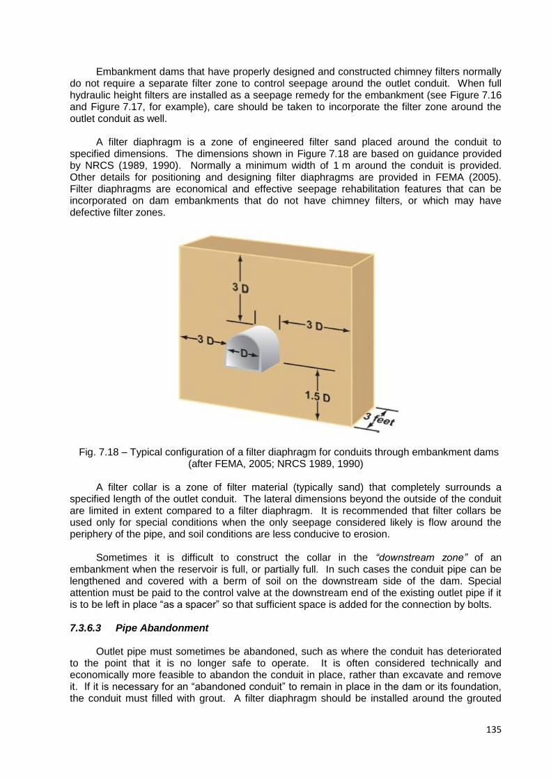
135
Embankment dams that have properly designed and constructed chimney filters normally do not require a separate filter zone to control seepage around the outlet conduit. When full hydraulic height filters are installed as a seepage remedy for the embankment (see Figure 7.16 and Figure 7.17, for example), care should be taken to incorporate the filter zone around the outlet conduit as well.
A filter diaphragm is a zone of engineered filter sand placed around the conduit to
specified dimensions. The dimensions shown in Figure 7.18 are based on guidance provided by NRCS (1989, 1990). Normally a minimum width of 1 m around the conduit is provided. Other details for positioning and designing filter diaphragms are provided in FEMA (2005). Filter diaphragms are economical and effective seepage rehabilitation features that can be incorporated on dam embankments that do not have chimney filters, or which may have defective filter zones.
Fig. 7.18 – Typical configuration of a filter diaphragm for conduits through embankment dams
(after FEMA, 2005; NRCS 1989, 1990)
A filter collar is a zone of filter material (typically sand) that completely surrounds a specified length of the outlet conduit. The lateral dimensions beyond the outside of the conduit are limited in extent compared to a filter diaphragm. It is recommended that filter collars be used only for special conditions when the only seepage considered likely is flow around the periphery of the pipe, and soil conditions are less conducive to erosion.
Sometimes it is difficult to construct the collar in the “downstream zone” of an
embankment when the reservoir is full, or partially full. In such cases the conduit pipe can be lengthened and covered with a berm of soil on the downstream side of the dam. Special attention must be paid to the control valve at the downstream end of the existing outlet pipe if it is to be left in place “as a spacer” so that sufficient space is added for the connection by bolts.
7.3.6.3 Pipe Abandonment
Outlet pipe must sometimes be abandoned, such as where the conduit has deteriorated
to the point that it is no longer safe to operate. It is often considered technically and economically more feasible to abandon the conduit in place, rather than excavate and remove it. If it is necessary for an “abandoned conduit” to remain in place in the dam or its foundation, the conduit must filled with grout. A filter diaphragm should be installed around the grouted
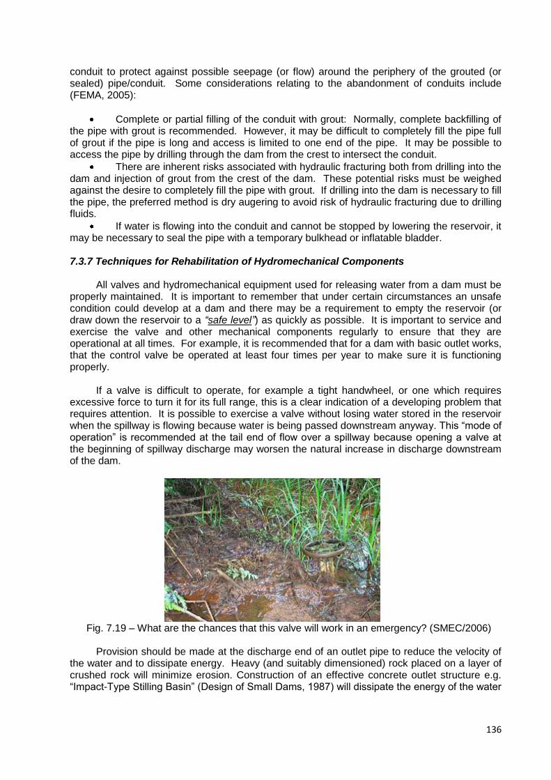
136
conduit to protect against possible seepage (or flow) around the periphery of the grouted (or sealed) pipe/conduit. Some considerations relating to the abandonment of conduits include (FEMA, 2005):
Complete or partial filling of the conduit with grout: Normally, complete backfilling of the pipe with grout is recommended. However, it may be difficult to completely fill the pipe full of grout if the pipe is long and access is limited to one end of the pipe. It may be possible to access the pipe by drilling through the dam from the crest to intersect the conduit.
There are inherent risks associated with hydraulic fracturing both from drilling into the dam and injection of grout from the crest of the dam. These potential risks must be weighed against the desire to completely fill the pipe with grout. If drilling into the dam is necessary to fill the pipe, the preferred method is dry augering to avoid risk of hydraulic fracturing due to drilling fluids.
If water is flowing into the conduit and cannot be stopped by lowering the reservoir, it may be necessary to seal the pipe with a temporary bulkhead or inflatable bladder.
7.3.7 Techniques for Rehabilitation of Hydromechanical Components
All valves and hydromechanical equipment used for releasing water from a dam must be
properly maintained. It is important to remember that under certain circumstances an unsafe condition could develop at a dam and there may be a requirement to empty the reservoir (or draw down the reservoir to a “safe level”) as quickly as possible. It is important to service and exercise the valve and other mechanical components regularly to ensure that they are operational at all times. For example, it is recommended that for a dam with basic outlet works, that the control valve be operated at least four times per year to make sure it is functioning properly.
If a valve is difficult to operate, for example a tight handwheel, or one which requires
excessive force to turn it for its full range, this is a clear indication of a developing problem that requires attention. It is possible to exercise a valve without losing water stored in the reservoir when the spillway is flowing because water is being passed downstream anyway. This “mode of operation” is recommended at the tail end of flow over a spillway because opening a valve at the beginning of spillway discharge may worsen the natural increase in discharge downstream of the dam.
Fig. 7.19 – What are the chances that this valve will work in an emergency? (SMEC/2006)
Provision should be made at the discharge end of an outlet pipe to reduce the velocity of
the water and to dissipate energy. Heavy (and suitably dimensioned) rock placed on a layer of crushed rock will minimize erosion. Construction of an effective concrete outlet structure e.g. “Impact-Type Stilling Basin” (Design of Small Dams, 1987) will dissipate the energy of the water
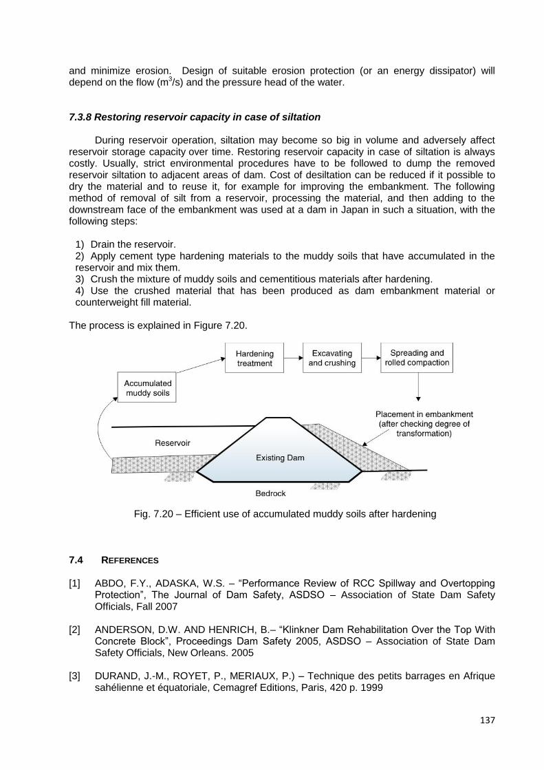
137
and minimize erosion. Design of suitable erosion protection (or an energy dissipator) will depend on the flow (m3/s) and the pressure head of the water.
7.3.8 Restoring reservoir capacity in case of siltation
During reservoir operation, siltation may become so big in volume and adversely affect reservoir storage capacity over time. Restoring reservoir capacity in case of siltation is always costly. Usually, strict environmental procedures have to be followed to dump the removed reservoir siltation to adjacent areas of dam. Cost of desiltation can be reduced if it possible to dry the material and to reuse it, for example for improving the embankment. The following method of removal of silt from a reservoir, processing the material, and then adding to the downstream face of the embankment was used at a dam in Japan in such a situation, with the following steps:
1) Drain the reservoir. 2) Apply cement type hardening materials to the muddy soils that have accumulated in the reservoir and mix them. 3) Crush the mixture of muddy soils and cementitious materials after hardening. 4) Use the crushed material that has been produced as dam embankment material or counterweight fill material.
The process is explained in Figure 7.20.
Fig. 7.20 – Efficient use of accumulated muddy soils after hardening
7.4 REFERENCES
[1] ABDO, F.Y., ADASKA, W.S. – “Performance Review of RCC Spillway and Overtopping Protection”, The Journal of Dam Safety, ASDSO – Association of State Dam Safety Officials, Fall 2007
[2] ANDERSON, D.W. AND HENRICH, B.– “Klinkner Dam Rehabilitation Over the Top With
Concrete Block”, Proceedings Dam Safety 2005, ASDSO – Association of State Dam Safety Officials, New Orleans. 2005
[3] DURAND, J.-M., ROYET, P., MERIAUX, P.) – Technique des petits barrages en Afrique
sahélienne et équatoriale, Cemagref Editions, Paris, 420 p. 1999

138
[4] FEMA – “Technical Manual: Conduits through Embankment Dams, Best Practices for
Design, Construction, Problem Identification and Evaluation, Inspection, Maintenance, Renovation, and Repair,” U.S. Federal Emergency Management Agency FEMA 484DVD/September 2005.
[5] HANSEN, K.D AND KAHLER, C.M. “RCC Tests, Testing , and Test Sections – Lessons
Learned,” Journal of Dam Safety, ASDSO, Vol.2, No. 1 pp. 12-17. 2004
[6] JSIDRE– “Design Guideline for Agricultural Land Improvement Projects – Tameike Rehabilitation”, Japan. 2006
[7] KOERNER, R.M. AND HSUAN, Y.G. – “Lifetime Prediction of Polymeric Geomembranes
used in New Dam Construction and Dam Rehabilitation”, Proc. ASDSO Dam Safety Conference, Lake Harmony 2003
[8] LAUTRIN, D.– Vieillisement et réhabilitation des petits barrages en terre, Cemagref
Editions, Paris, 240 p. 2003
[9] LEWIS, B. – “Minimum Energy Design Using Grassed Spillways”, ASDSO Dam Safety Conference, Boston. 2006
[10] LONDE, M. PIERRE, “Lessons from Earth Dam Failures”, News and Views, British
National Committee on Large Dams (London August 1983).
[11] MILLER, D.J., JEWELL, A.C., AND SMITH, K. – “Piping and internal erosion control measures at Tongue River Dam, Montana,” Proc. Assoc. State Dam Safety Officials, Snowbird, UT, USA, Sept 11. 2001
[12] MILLER, S.P.; RALSTON, D.C.– “Embankment Overtopping – Case Histories”, R.M.
Ragan editor. Hydraulic Engineering Proc. Of the 1987 Conf. on Hydraulic Engineering, Virginia, ASCE. 1987
[13] NRCS– “Dimensioning of Filter Drainage Diaphragms for Conduits According to TR 60”,
Natural Resources Conservation Service, Technical Note No. 709, U.S. Dept. Agriculture. 1989
[14] NRCS– “Earth Dams and Reservoirs”, Natural Resources Conservation Service,
Technical Release No. 60 (TR 60), U.S. Dept. Agriculture. 1989
[15] SHERARD, J. L., DUNNIGAN, L. P., "Filters and Leakage Control in Embankment Dams, Symposium on Seepage and Leakage from Dams and Impoundments, ASCE, May. 1985
[16] SHERARD, J. L., DUNNIGAN, L. P., "Critical Filters for Impervious Soils, Journal of
Geotechnical Engineering, ASCE, July. 1989
[17] SHERARD, J. L., DUNNIGAN, L. P., AND TALBOT, J. R., "Basic Properties of Sand and Gravel Filters," Journal of Geotechnical Engineering, ASCE, June. 1984a
[18] SHERARD, J. L., DUNNIGAN, L. P., AND TALBOT, J. R., "Filters for Silts and Clays,"
Journal of Geotechnical Engineering, ASCE, June. 1984b
[19] SINGH, N., DOUGLAS, R., AHLFIELD, S. AND GANT, M.– “Construction of a Roller-Compacted Concrete Upstream Blanket and Plastic Concrete Cutoff Wall at Cleveland Dam,” Proc. Assoc. State Dam Safety Officials, Orlando Florida, USA, Sept 22-27. 2005

139
[20] SMEC– “Draft Guidelines for Managing Small Dams”, SMEC Australia Pty Ltd. 2006
[21] TANI AND FUKUSHIMA – “Sampling Studies of Rehabilitation Works for Aged Fill
Dams,” 2007, The Agricultural Research Institute Report, Japan. 2007
[22] BUREAU OF RECLAMATION – “Design of Small Dams”, United States Department of the Interior, A Water Resources Technical Publication, Third Edition, 1987. Pages 463 to 464. 1987
[23] USACE– “Technologies and Techniques for Drainage Pipe Maintenance and Repair – A
Practical Guide for Technology Selection”, prepared by Civil Engineering Research Foundation, U.S. Army Corps of Engineers, May. 2001
[24] VELLONE, D.A. AND STIER, M.A.– “Rehabilitation an Aging Embankment Dam with
RCC for Overtopping Protection”, Proc. ASDSO Dam Safety Conference, New Orleans. 2005
[25] WEAVER, K. AND BRUCE, D.– “Dam Foundation Grouting”, American Soc. Civil
Engineers Press No. 0-7844-0764-9, Reston, Virginia, U.S.A. 2007
[26] VAN SCHALKWYK, A.– “Erosion of rock in unlined spillways” Paper Release 37 as part of The Eighteenth Congress on Large Dams, Durban 1994, Volume IV, Question 71. 1994
[27] KIRSTEN, H.A.D. – A classification system for excavation in natural materials. The Civil
Engineer of South Africa, July 1982. Pages 293 – 308. 1982

140
8. GUIDELINES ON EMERGENCY ACTION PLAN (EAP)
8.1 INTRODUCTION
The EAP is a useful tool intended to minimize the consequences of a dam failure or malfunction, regarding the population living downstream. In the last 30 years, several countries became aware of the new approach requested by modern society and developed regulations on this matter, creating a dam classification system according to potential downstream hazard and establishing the EAP for dams with a high significant risk
Initially the EAP was applied to medium and large dams, and nowadays it is also applied to small dams as a consequence of the great number of such structures and that 87% of the victims related to dam failures have been caused by small dams, according to the experience in the United States - Bureau of Reclamation, along the period from 1970 to 1997. It is interesting to point out from this experience, that 99% of the victims were situated along the 24 km downstream of the dams.
The Emergency Action Plan typically falls under the preventive measures to be taken regarding dams safety. For many years these aspects have been taken into account in different regulations and more demanding safety criteria has been established for those dams in which failure or malfunction, even with a very low probability, may cause severe consequences to the downstream population.
The purpose of this document is to provide findings, recommendations and strategies to significantly increase the application of Emergency Action Plans to high hazard small dams. The recommendations and strategies can be implemented by policymakers, state and local dam safety officials and dam owners, with the collaboration of the state and local emergency agencies. An EAP is essential for small dam owners and first responders in the event of a dam failure resulting from a natural event (such as a big storm or earthquake), from an accident or from a manmade event.
8.2 HOW TO DEVELOP AN EMERGENCY ACTION PLAN
The process of developing an EAP for a small dam generally follows the next steps, as pointed out by Abadjiev [2]:
Determine the potential inundated area downstream in case of a dam failure. Two scenarios are to be considered: inundation at maximum probable flood through the spillway without dam failure, and inundation with dam failure. Different failures according to their reasons and development are to be considered as overtopping, piping, etc.
Prepare inundation maps clearly indicating the flooded areas and the time at which the wave will reach the downstream settlement or important area.
Determine and identify the situations and events that could initiate an emergency action and specify the corresponding actions to be taken and by whom. Develop clear instructions to explain how the operation staff must react before and during emergency.
Identify all entities, jurisdictions, agencies and individuals, who will be involved in the emergency actions. Coordinate the development of the EAP with all parties. This interaction should include the discussion of an emergency operation center and discussion of the evacuation with destinations, priorities and procedures, post-flood actions (recovery and cleanup) and all other measures. These discussions must be concise and productive, and

141
present visual information. It must be underlined that the development of an EAP does not mean that the dam is not safe. It is advisable that all parties and the public are invited to participate in a visual inspection of the dam because they can bring practical suggestions that could be taken into account. All parties, including the public, must feel involved in the EAP.
Identify all primary and auxiliary communication systems for continuously internal and external communication.
List and prioritize all persons and entities involved in the notification process and create the notification flowchart.
Develop a draft of the EAP. The list of the tasks must be complete (nothing should be omitted) and easy to understand so that it can be readily followed.
Determine the responsibilities under the plan:
- owner responsibility
- responsibility for notification
- responsibility for evacuation
- EAP coordinator responsibility
The EAP should foresee actions prior to and following the development of emergency
conditions. These actions include:
- surveillance
- access to the site
- response during periods of darkness
- response during periods of adverse weather
- emergency supplies, resources and transport means
- alternative means of communication
- coordinating information on flows
Review and discuss the EAP draft with all parties included in the notification list. The EAP must be clearly understood by everyone. The public (community) should also be invited to participate in the EAP revision meeting because their involvement helps in the elaboration of a better EAP and also gives support to the emergency actions.
In the following paragraphs the main points of the establishment of an EAP are analyzed.
8.3 EVALUATION OF POSSIBLE RISKS In the event of a dam failure, the potential energy of the water stored behind even a small dam is capable of causing loss of life, serious property damage and an extended period of absence of the services that dams provide.
The EAP should be applied to all small dams with a high hazard potential, which is directly correlated to the population, properties and the environment downstream. It is important to analyze and evaluate the possible dam hazards, in order to perform a more rational approach to the EAP establishment.
8.3.1 Overtopping During Extremes Floods
Considering that about 90% of all small dams are embankment dams, and that 2/3 of those dams have failed as a consequence of extreme floods, it is very important to perform a thorough revision of the spillway or outlet structures, in order to evaluate its maximum discharge and compare it with the maximum flood calculated based on more up to data values from the dam site and the basin contribution area.
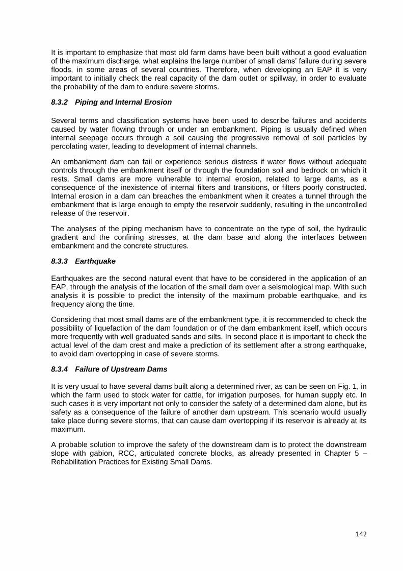
142
It is important to emphasize that most old farm dams have been built without a good evaluation of the maximum discharge, what explains the large number of small dams’ failure during severe floods, in some areas of several countries. Therefore, when developing an EAP it is very important to initially check the real capacity of the dam outlet or spillway, in order to evaluate the probability of the dam to endure severe storms.
8.3.2 Piping and Internal Erosion
Several terms and classification systems have been used to describe failures and accidents caused by water flowing through or under an embankment. Piping is usually defined when internal seepage occurs through a soil causing the progressive removal of soil particles by percolating water, leading to development of internal channels.
An embankment dam can fail or experience serious distress if water flows without adequate controls through the embankment itself or through the foundation soil and bedrock on which it rests. Small dams are more vulnerable to internal erosion, related to large dams, as a consequence of the inexistence of internal filters and transitions, or filters poorly constructed. Internal erosion in a dam can breaches the embankment when it creates a tunnel through the embankment that is large enough to empty the reservoir suddenly, resulting in the uncontrolled release of the reservoir.
The analyses of the piping mechanism have to concentrate on the type of soil, the hydraulic gradient and the confining stresses, at the dam base and along the interfaces between embankment and the concrete structures.
8.3.3 Earthquake
Earthquakes are the second natural event that have to be considered in the application of an EAP, through the analysis of the location of the small dam over a seismological map. With such analysis it is possible to predict the intensity of the maximum probable earthquake, and its frequency along the time.
Considering that most small dams are of the embankment type, it is recommended to check the possibility of liquefaction of the dam foundation or of the dam embankment itself, which occurs more frequently with well graduated sands and silts. In second place it is important to check the actual level of the dam crest and make a prediction of its settlement after a strong earthquake, to avoid dam overtopping in case of severe storms.
8.3.4 Failure of Upstream Dams
It is very usual to have several dams built along a determined river, as can be seen on Fig. 1, in which the farm used to stock water for cattle, for irrigation purposes, for human supply etc. In such cases it is very important not only to consider the safety of a determined dam alone, but its safety as a consequence of the failure of another dam upstream. This scenario would usually take place during severe storms, that can cause dam overtopping if its reservoir is already at its maximum.
A probable solution to improve the safety of the downstream dam is to protect the downstream slope with gabion, RCC, articulated concrete blocks, as already presented in Chapter 5 – Rehabilitation Practices for Existing Small Dams.
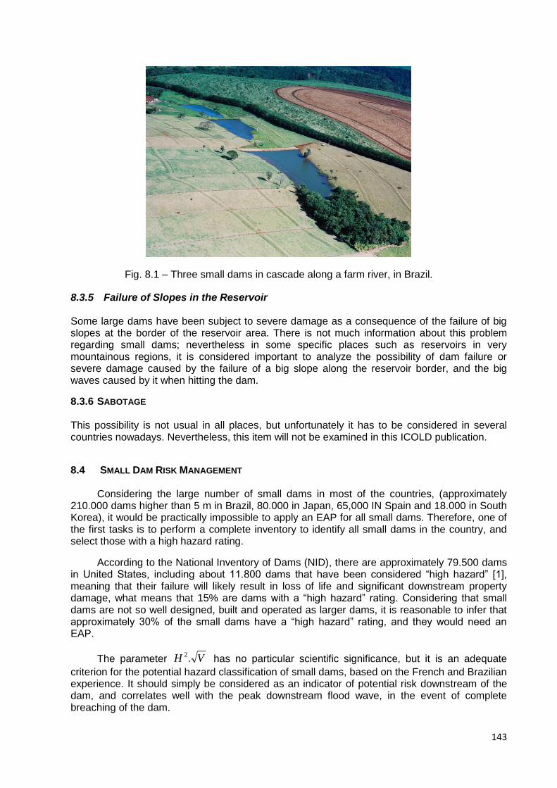
143
Fig. 8.1 – Three small dams in cascade along a farm river, in Brazil.
8.3.5 Failure of Slopes in the Reservoir
Some large dams have been subject to severe damage as a consequence of the failure of big slopes at the border of the reservoir area. There is not much information about this problem regarding small dams; nevertheless in some specific places such as reservoirs in very mountainous regions, it is considered important to analyze the possibility of dam failure or severe damage caused by the failure of a big slope along the reservoir border, and the big waves caused by it when hitting the dam.
8.3.6 SABOTAGE
This possibility is not usual in all places, but unfortunately it has to be considered in several countries nowadays. Nevertheless, this item will not be examined in this ICOLD publication.
8.4 SMALL DAM RISK MANAGEMENT
Considering the large number of small dams in most of the countries, (approximately
210.000 dams higher than 5 m in Brazil, 80.000 in Japan, 65,000 IN Spain and 18.000 in South Korea), it would be practically impossible to apply an EAP for all small dams. Therefore, one of the first tasks is to perform a complete inventory to identify all small dams in the country, and select those with a high hazard rating.
According to the National Inventory of Dams (NID), there are approximately 79.500 dams in United States, including about 11.800 dams that have been considered “high hazard” [1], meaning that their failure will likely result in loss of life and significant downstream property damage, what means that 15% are dams with a “high hazard” rating. Considering that small dams are not so well designed, built and operated as larger dams, it is reasonable to infer that approximately 30% of the small dams have a “high hazard” rating, and they would need an EAP.
The parameter VH .2 has no particular scientific significance, but it is an adequate
criterion for the potential hazard classification of small dams, based on the French and Brazilian experience. It should simply be considered as an indicator of potential risk downstream of the dam, and correlates well with the peak downstream flood wave, in the event of complete breaching of the dam.
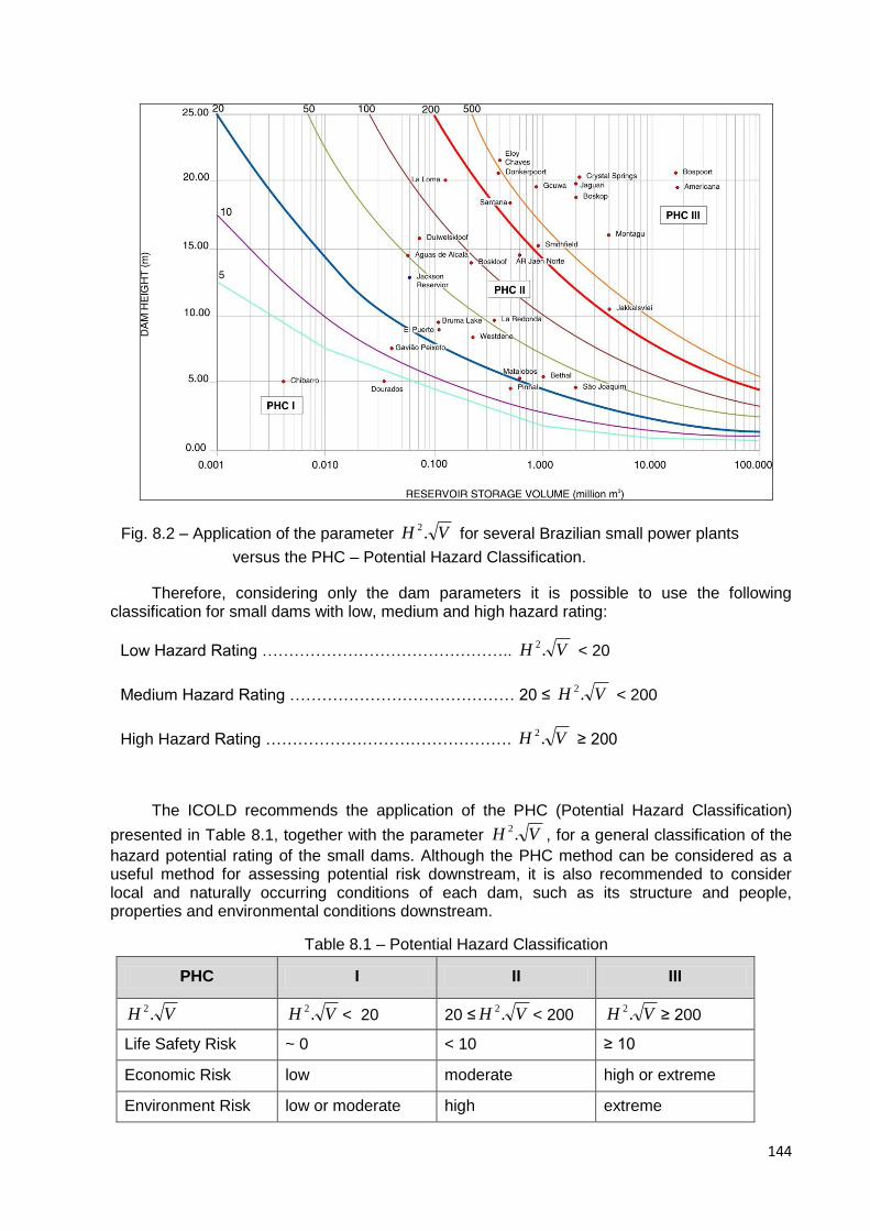
144
Fig. 8.2 – Application of the parameter VH .2 for several Brazilian small power plants
versus the PHC – Potential Hazard Classification.
Therefore, considering only the dam parameters it is possible to use the following classification for small dams with low, medium and high hazard rating:
Low Hazard Rating ……………………………………….. VH .2 < 20
Medium Hazard Rating …………………………………… 20 ≤ VH .2 < 200
High Hazard Rating ………………………………………. VH .2 ≥ 200
The ICOLD recommends the application of the PHC (Potential Hazard Classification)
presented in Table 8.1, together with the parameter VH .2, for a general classification of the
hazard potential rating of the small dams. Although the PHC method can be considered as a useful method for assessing potential risk downstream, it is also recommended to consider local and naturally occurring conditions of each dam, such as its structure and people, properties and environmental conditions downstream.
Table 8.1 – Potential Hazard Classification
PHC I II III
VH .2 VH .2
< 20 20 ≤ VH .2< 200 VH .2
≥ 200
Life Safety Risk ~ 0 < 10 ≥ 10
Economic Risk low moderate high or extreme
Environment Risk low or moderate high extreme
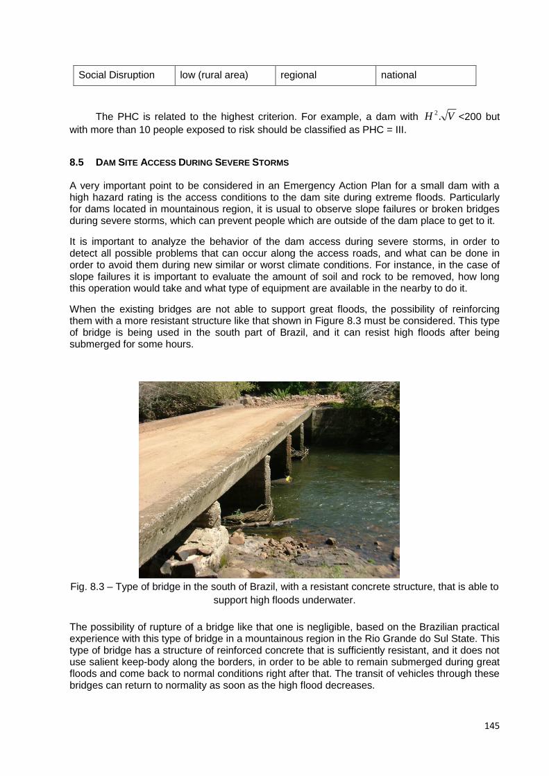
145
Social Disruption low (rural area) regional national
The PHC is related to the highest criterion. For example, a dam with VH .2<200 but
with more than 10 people exposed to risk should be classified as PHC = III.
8.5 DAM SITE ACCESS DURING SEVERE STORMS
A very important point to be considered in an Emergency Action Plan for a small dam with a high hazard rating is the access conditions to the dam site during extreme floods. Particularly for dams located in mountainous region, it is usual to observe slope failures or broken bridges during severe storms, which can prevent people which are outside of the dam place to get to it.
It is important to analyze the behavior of the dam access during severe storms, in order to detect all possible problems that can occur along the access roads, and what can be done in order to avoid them during new similar or worst climate conditions. For instance, in the case of slope failures it is important to evaluate the amount of soil and rock to be removed, how long this operation would take and what type of equipment are available in the nearby to do it.
When the existing bridges are not able to support great floods, the possibility of reinforcing them with a more resistant structure like that shown in Figure 8.3 must be considered. This type of bridge is being used in the south part of Brazil, and it can resist high floods after being submerged for some hours.
Fig. 8.3 – Type of bridge in the south of Brazil, with a resistant concrete structure, that is able to
support high floods underwater.
The possibility of rupture of a bridge like that one is negligible, based on the Brazilian practical experience with this type of bridge in a mountainous region in the Rio Grande do Sul State. This type of bridge has a structure of reinforced concrete that is sufficiently resistant, and it does not use salient keep-body along the borders, in order to be able to remain submerged during great floods and come back to normal conditions right after that. The transit of vehicles through these bridges can return to normality as soon as the high flood decreases.
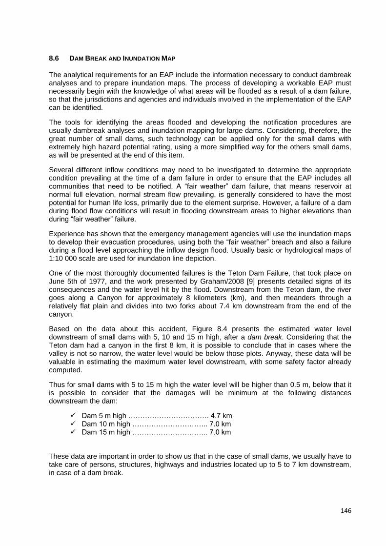
146
8.6 DAM BREAK AND INUNDATION MAP
The analytical requirements for an EAP include the information necessary to conduct dambreak analyses and to prepare inundation maps. The process of developing a workable EAP must necessarily begin with the knowledge of what areas will be flooded as a result of a dam failure, so that the jurisdictions and agencies and individuals involved in the implementation of the EAP can be identified.
The tools for identifying the areas flooded and developing the notification procedures are usually dambreak analyses and inundation mapping for large dams. Considering, therefore, the great number of small dams, such technology can be applied only for the small dams with extremely high hazard potential rating, using a more simplified way for the others small dams, as will be presented at the end of this item.
Several different inflow conditions may need to be investigated to determine the appropriate condition prevailing at the time of a dam failure in order to ensure that the EAP includes all communities that need to be notified. A “fair weather” dam failure, that means reservoir at normal full elevation, normal stream flow prevailing, is generally considered to have the most potential for human life loss, primarily due to the element surprise. However, a failure of a dam during flood flow conditions will result in flooding downstream areas to higher elevations than during “fair weather” failure.
Experience has shown that the emergency management agencies will use the inundation maps to develop their evacuation procedures, using both the “fair weather” breach and also a failure during a flood level approaching the inflow design flood. Usually basic or hydrological maps of 1:10 000 scale are used for inundation line depiction.
One of the most thoroughly documented failures is the Teton Dam Failure, that took place on June 5th of 1977, and the work presented by Graham/2008 [9] presents detailed signs of its consequences and the water level hit by the flood. Downstream from the Teton dam, the river goes along a Canyon for approximately 8 kilometers (km), and then meanders through a relatively flat plain and divides into two forks about 7.4 km downstream from the end of the canyon.
Based on the data about this accident, Figure 8.4 presents the estimated water level downstream of small dams with 5, 10 and 15 m high, after a dam break. Considering that the Teton dam had a canyon in the first 8 km, it is possible to conclude that in cases where the valley is not so narrow, the water level would be below those plots. Anyway, these data will be valuable in estimating the maximum water level downstream, with some safety factor already computed.
Thus for small dams with 5 to 15 m high the water level will be higher than 0.5 m, below that it is possible to consider that the damages will be minimum at the following distances downstream the dam:
Dam 5 m high ……………………………. 4.7 km Dam 10 m high ………………………….. 7.0 km Dam 15 m high ………………………….. 7.0 km
These data are important in order to show us that in the case of small dams, we usually have to take care of persons, structures, highways and industries located up to 5 to 7 km downstream, in case of a dam break.
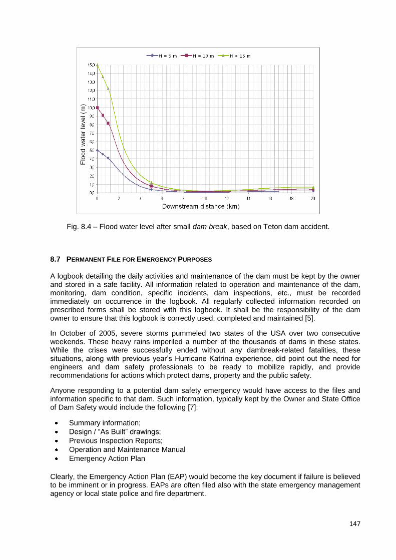
147
Fig. 8.4 – Flood water level after small dam break, based on Teton dam accident.
8.7 PERMANENT FILE FOR EMERGENCY PURPOSES
A logbook detailing the daily activities and maintenance of the dam must be kept by the owner and stored in a safe facility. All information related to operation and maintenance of the dam, monitoring, dam condition, specific incidents, dam inspections, etc., must be recorded immediately on occurrence in the logbook. All regularly collected information recorded on prescribed forms shall be stored with this logbook. It shall be the responsibility of the dam owner to ensure that this logbook is correctly used, completed and maintained [5].
In October of 2005, severe storms pummeled two states of the USA over two consecutive weekends. These heavy rains imperiled a number of the thousands of dams in these states. While the crises were successfully ended without any dambreak-related fatalities, these situations, along with previous year’s Hurricane Katrina experience, did point out the need for engineers and dam safety professionals to be ready to mobilize rapidly, and provide recommendations for actions which protect dams, property and the public safety.
Anyone responding to a potential dam safety emergency would have access to the files and information specific to that dam. Such information, typically kept by the Owner and State Office of Dam Safety would include the following [7]:
Summary information;
Design / “As Built” drawings;
Previous Inspection Reports;
Operation and Maintenance Manual
Emergency Action Plan
Clearly, the Emergency Action Plan (EAP) would become the key document if failure is believed to be imminent or in progress. EAPs are often filed also with the state emergency management agency or local state police and fire department.
148
Realistically however, in many response situations, as concluded by Cox/2007 based on practical experience, an engineer or inspector will not have quick access to these files. And in some cases, even when the files are available not all critical information may be included.
It is very important to arrive on site with the right equipment, as pointed out by Cox/2007 [7]. It should not be expected that the first engineer or inspector on site will come equipped to repair problems, but the following is a list of equipment which might prove useful when responding a top dam safety emergency, and then need to be prepared previously:
Filed book and pencils
Clip board
Digital camera (extra batteries)
Cell phone (with important number of batteries);
Measuring tape
Flashlight (extra batteries)
Rain gear and umbrella
Calculator
Laptop (with wireless internet connection)
Stake or ruler for staff gauge
GPS Unit
Tracer dye.
Since the collection of such equipment takes time, it is generally a good idea to preassemble a “ready bag” or plastic tube with all necessary equipment so that it is ready to be loaded into a vehicle on short notice.
Personal safety gear such as high-visibility clothing, flotation devices and hard hats should be available.
8.8 EMERGENCY EXERCISING AND UPDATING
Emergency incidents at dams and dam failures are not common events. Training exercises are necessary to maintain operation readiness, timeliness and responsiveness. This may accomplished through development and conduct of an emergency exercise program. It is recommended that detailed guidelines on developing and implementing Emergency Action Plan will be used in these situations.
Warning and evacuation plans should be considered “living” documents, as pointed out by the Bureau of Reclamation [1]. This means that:
1. They will never be completed; 2. They should be reviewed not less than each five years for small dams; 3. Review should include participation of personnel of the dam operating organization, and
local authorities when possible; 4. All updates should be made promptly.
Changes that may frequently require revision and update of emergency action plans include changes in personnel of involved organizations and changes in communications systems. As a minimum, review of office telephone numbers and appropriate personnel included in notification flowcharts should be conducted.
During the review of warning and evacuating plan, a comprehensive evaluation of the adequacy of the plan should be made as well.
149
8.9 REFERENCES
[1] BURREC (1994) – “Emergency Action Planning Guidelines For Dams and Reservoirs”,
U.S. Department of the Interior, Bureau of Reclamation;
[2] ABADJIEV, C.B. (2009) – Personal contribution received from Bulgaria;
[3] FEMA (2007) – “Emergency Action Planning for State Regulated High-Hazard Potential
Dams, Findings, Recommendations and Strategies”, FEMA 708, August 2007;
[4] LOPEZ, L.A., MARTINEZ, F.J.S., CORDBA, J.Y. (2004) – “The Emergency Action Plans
in Spain”, Annual Conference from the ASDSO – Association of State Dam Safety
Officials, Sept 2004;
[5] SMEC (2007) – “Draft Guidelines for Managing Small Dams”, The Republic of Uganda –
Appendix D, SMEC Australia Pty Ltd, Feb 2007;
[6] BADENHORST, D.B. (2004) – “Vygeboom Dam: Operation, Maintenance Manual and
Emergency Plan”, South Africa;
[7] COX, C.W. (2007) – “Dam Emergency Response Suggestions for a Dam Safety
Engineer’s Toolkit and Checklist ”, Annual Conference from the ASDSO – Association of
State Dam Safety Officials, Sept 2007, Boston;
[8] JINBAO, S., LEI, L.,ZHAOSHENG, W., XUEHUI, P., SHICHEN, Z. (2007) – “Small Dam
Safety and Risk Management in China”, ICOLD 75th Annual Meeting, Saint Petersburg,
Russia;
[9] GRAHAM, W.J. (2008) – “The Teton Dam Failure: Factors Affecting the Warning and
Evacuation Success”, International Conference on Dam Safety Management, Nanjing,
China.