
SMA MEDIUM VOLTAGE POWER PLATFORMS - Power …files.sma.de/dl/15775/SC_MVPP System-TDC-EN-10.pdf ·...
41
SC_MVPP System-TDC-EN-10|Version 1.0 US SMA Medium Voltage Power Platforms Power Platform System Overview Technical Description
Transcript of SMA MEDIUM VOLTAGE POWER PLATFORMS - Power …files.sma.de/dl/15775/SC_MVPP System-TDC-EN-10.pdf ·...

SC_MVPP System-TDC-EN-10|Version 1.0 US
SMA Medium Voltage Power Platforms Power Platform System Overview Technical Description
Legal Restrictions SMA America, LLC
2 SC_MVPP System-TDC-EN-10 Technical Description
opyright © 2011 SMA America, LLC. All rights reserved. trieval system, or transmitted, in any
nology Canada Inc. makes no representations,
er
lied warranties may not apply in all cases under some statutes, and thus the
e without notice. Every attempt has been made to make this ca,
rately. Missing designations do
ned by Bluetooth SIG, Inc. and
SMA America, LLC 3801 N. Havana Street
D
SMA Solar Technology Canada Inc.
Mississau W 5K5
CNo part of this document may be reproduced, stored in a reform or by any means, electronic, mechanical, photographic, magnetic or otherwise, without the prior written permission of SMA America, LLC. Neither SMA America, LLC nor SMA Solar Techexpress or implied, with respect to this documentation or any of the equipment and/or software itmay describe, including (with no limitation) any implied warranties of utility, merchantability, or fitness for any particular purpose. All such warranties are expressly disclaimed. Neither SMA America, LLC nor its distributors or dealers nor SMA Solar Technology Canada Inc. nor its distributors or dealers shall be liable for any indirect, incidental, or consequential damages undany circumstances. (The exclusion of impabove exclusion may not apply.) Specifications are subject to changdocument complete, accurate and up-to-date. Readers are cautioned, however, that SMA AmeriLLC and SMA Solar Technology Canada Inc. reserve the right to make changes without notice and shall not be responsible for any damages, including indirect, incidental or consequential damages, caused by reliance on the material presented, including, but not limited to, omissions, typographical errors, arithmetical errors or listing errors in the content material. All trademarks are recognized even if these are not marked sepanot mean that a product or brand is not a registered trademark. The Bluetooth® word mark and logos are registered trademarks owany use of such marks by SMA America, LLC and SMA Solar Technology Canada Inc. is under license.
enver, CO 80239 U.S.A.
2425 Matheson Blvd 8th Floor ga, ON L4Canada

SMA America, LLC Table of Contents
Table of contents 1 List of Abbreviations................................................................... 6 2 General ....................................................................................... 7 2.1 Scope of Document ............................................................................ 7 2.2 Summary of Design ............................................................................. 7 2.3 Power Classes and Option Codes .................................................... 8 2.3.1 Option Codes ...........................................................................................................9 2.3.2 MVPP Base Platform Option Descriptions ........................................................... 10 2.3.3 Control and Supply Panel Option Descriptions .................................................. 13 2.3.4 Example Option Code: ......................................................................................... 14 2.4 System Description ........................................................................... 15 2.4.1 Scope of Supply .................................................................................................... 15 2.4.2 Exclusions .............................................................................................................. 15
3 Compliance .............................................................................. 16 3.1 List of Standards ............................................................................... 16 3.1.1 Platform / System Applicable Standards ............................................................ 16 3.1.2 Auxiliary Transformer Applicable Standards....................................................... 17 3.1.3 Control and Supply Panel Applicable Standards ............................................... 18
4 MVPP Mechanical Design ....................................................... 20 4.1 Design Variants ................................................................................ 20 4.1.1 Open Platform ....................................................................................................... 20 4.1.2 Platform with Canopy ........................................................................................... 21 4.1.3 Enclosed Platform .................................................................................................. 22 4.2 Materials .......................................................................................... 23 4.3 Integration ........................................................................................ 24 4.3.1 Mechanical............................................................................................................ 24 4.3.2 Electrical ................................................................................................................ 24
Technical Description SC_MVPP System-TDC-EN-10 3

Table of Contents SMA America, LLC
4.4 Mechanical and Environmental Data ............................................. 25 5 Electrical Design ....................................................................... 26 5.1 System Electrical Overview ............................................................. 26 5.2 Electrical Data .................................................................................. 27 6 Control and Supply Panel ....................................................... 29 6.1 Space and Supply for Customer Equipment .................................. 30 6.2 Components ..................................................................................... 30 6.2.1 Heater against Condensation .............................................................................. 30 6.2.2 Hygrostat ............................................................................................................... 30 6.2.3 Receptacles ........................................................................................................... 31 6.2.4 Power Supply ........................................................................................................ 31 6.2.5 Coupling Relay ...................................................................................................... 31 6.2.6 Circuit Breakers ..................................................................................................... 31 6.2.7 Fused Disconnect Switch ...................................................................................... 32 6.2.8 Ethernet pass-through Module ............................................................................. 32 6.2.9 Wire Duct .............................................................................................................. 32 6.2.10 Terminal Blocks .................................................................................................. 32 6.2.11 PE Bus Bar .......................................................................................................... 32 6.2.12 Surge Arrestor ................................................................................................... 33
4 SC_MVPP System-TDC-EN-10 Technical Description

SMA America, LLC Table of Contents
7 Low Temperature Range (option) .......................................... 34 7.1 Control Method ............................................................................... 34 8 Oil Containment (option) ........................................................ 36 8.1 Example of Oil Containment ........................................................... 37 9 Routine Testing ........................................................................ 38 9.1 Medium Voltage Power Platform .................................................... 38 9.2 Control and Supply Panel ............................................................... 38 10 Appendix ................................................................................. 39 10.1 Power Conductor Sizes ................................................................... 39 10.1.1 AC Conductors .................................................................................................. 39 10.1.2 DC Conductors .................................................................................................. 39
11 Contact ..................................................................................... 40
Technical Description SC_MVPP System-TDC-EN-10 5

Table of Contents SMA America, LLC
6 SC_MVPP System-TDC-EN-10 Technical Description
1 List of Abbreviations AC Alternating Current CB Circuit Breaker CSP Control and Supply Panel DC Direct Current FDS Fused Disconnect Switch LV Low Voltage MV Medium Voltage MVPP Medium Voltage Power Platform MVT Medium Voltage Transformer SC Sunny Central SCCR Short Circuit Current Rating

SMA America, LLC General
2 General 2.1 Scope of Document This document serves as the general Technical Description for SMA’s Medium Voltage Power Platforms. Technical information, compliance, and equipment descriptions are included to articulate the scope of delivery when purchasing an SMA Medium Voltage Power Platform. The scope of the technical information provided within this document applies to the MVPP as a system, including the base platform structure, interconnection of components, and Control and Supply panel. The technical data for the individual components integrated within the MVPP (i.e. inverters, disconnect units, and medium voltage transformer) are not included within this document. Separate Technical documentation is available for those component details.
2.2 Summary of Design The Medium Voltage Power Platform (henceforth, “MVPP”) is a comprehensive power conversion solution for utility scale photovoltaic plants in the US market. The MVPP is the interface between the photovoltaic output circuits from the array, and the medium voltage collector loop of the PV plant. It converts the direct current generated by the PV array, into alternating current, and transforms the inverter output power to match the voltage of the medium voltage grid to which it is connected.
Figure 1: Principle of a Utility Scale PV plant using the SMA Medium Voltage Power Platform
Technical Description SC_MVPP System-TDC-EN-10 7

General SMA America, LLC
Item Description A PV Array B Array String Combiners C SMA DC Disconnect Unit D SMA Sunny Central Inverters E Control and Supply Panel F Medium Voltage Step-up Transformer
G Medium Voltage Grid
2.3 Power Classes and Option Codes The MVPP is a configurable product, consisting of a suite of power classes and mechanical structures, as well as pre-engineered optional features. This enables a wide range of flexibility within a standardized product portfolio, to specify the specific needs for an individual PV Plant design. The available power classes are as outlined below. Unique SMA material numbers have been established to differentiate between the MVPPs deploying SMA Sunny Central HEUS inverters, SMA Sunny Central CP-XT inverters, and those deploying SMA’s UL listed, Sunny Central CP-US inverters. SMA Material Number Power Class / Inverter Type MV-1000HE-US 1000 kVA / SC500HE-US MV-1000CP-10 1000 kVA / SC500CP-XT MV-1000CP-US 1000 kVA / SC500CP-US MV-1250CP-10 1260 kVA / SC630CP-XT MV-1260CP-US 1260 kVA / SC630CP-US MV-1440CP-10 1440 kVA / SC720CP-XT MV-1440CP-US 1440 kVA / SC720CP-US MV-1500CP-10 1500 kVA / SC760CP-XT MV-1500CP-US 1500 kVA / SC750CP-US MV-1600CP-10 1600 kVA / SC800CP-XT MV-1600CP-UA 1600 kVA / SC800CP-US The different mechanical variants are identified within the MVPP option codes, as described in 1.3.1.
8 SC_MVPP System-TDC-EN-10 Technical Description
SMA America, LLC General
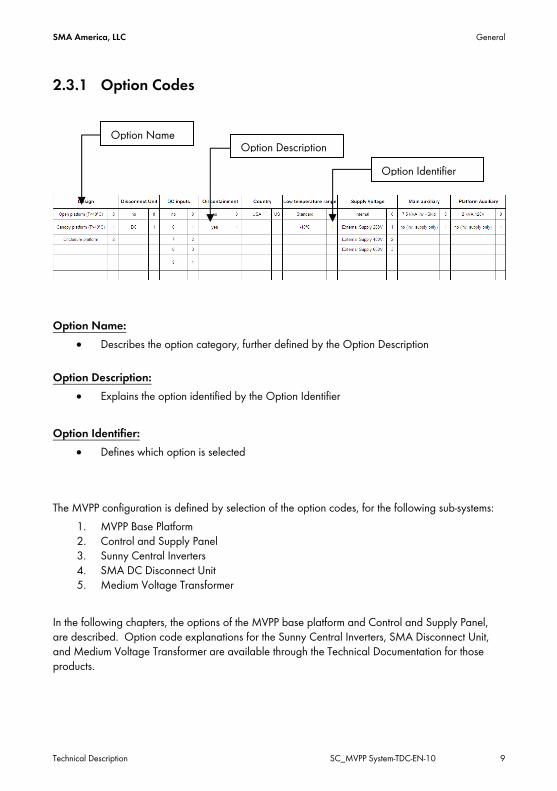
2.3.1 Option Codes
Option IdentifierOption Description
Option Name
Option Name:
• Describes the option category, further defined by the Option Description
Option Description: • Explains the option identified by the Option Identifier
Option Identifier:
• Defines which option is selected The MVPP configuration is defined by selection of the option codes, for the following sub-systems:
1. MVPP Base Platform 2. Control and Supply Panel 3. Sunny Central Inverters 4. SMA DC Disconnect Unit 5. Medium Voltage Transformer
In the following chapters, the options of the MVPP base platform and Control and Supply Panel, are described. Option code explanations for the Sunny Central Inverters, SMA Disconnect Unit, and Medium Voltage Transformer are available through the Technical Documentation for those products.
Technical Description SC_MVPP System-TDC-EN-10 9

General SMA America, LLC
2.3.2 MVPP Base Platform Option Descriptions
Design: Describes the structural variant of the MVPP 0 Open platform 1 Platform with shade canopy. Recommended for ambient conditions with temperatures
greater than 40°C with irradiance of 1000 W/m2 or higher. 2 Platform with complete enclosure structure surrounding equipment, except Medium Voltage
Transformer. Reference mechanical layouts for additional information. Disconnect Unit: Indicates if the SMA Disconnect Unit is included in the scope of supply, for disconnecting the DC array conductors from the inverter. The length of the MVPP is dependent upon (i) the option code “Design” and (ii) the inclusion of the Disconnect Unit. Note: this option code applies only to the SMA Disconnect Unit. Inclusion of 3rd party disconnect solutions is possible as a special version. 0 No 1 DC – SMA Disconnect Unit with DC load break switches included in scope of supply DC Inputs: Identifies the quantity of DC array conductors as inputs to each Disconnect Unit. This influences the required option code for the Disconnect Unit itself, and dictates the interface cabling between the Disconnect Unit, and the Sunny Central Inverter. 0 No – SMA Disconnect Unit has not been chosen in previous option code selection 1 6 – Each Disconnect Unit will receive (6) inputs from the PV array 2 7 – Each Disconnect Unit will receive (7) inputs from the PV array 3 8 – Each Disconnect Unit will receive (8) inputs from the PV array 4 9 – Each Disconnect Unit will receive (9) inputs from the PV array
10 SC_MVPP System-TDC-EN-10 Technical Description
SMA America, LLC General
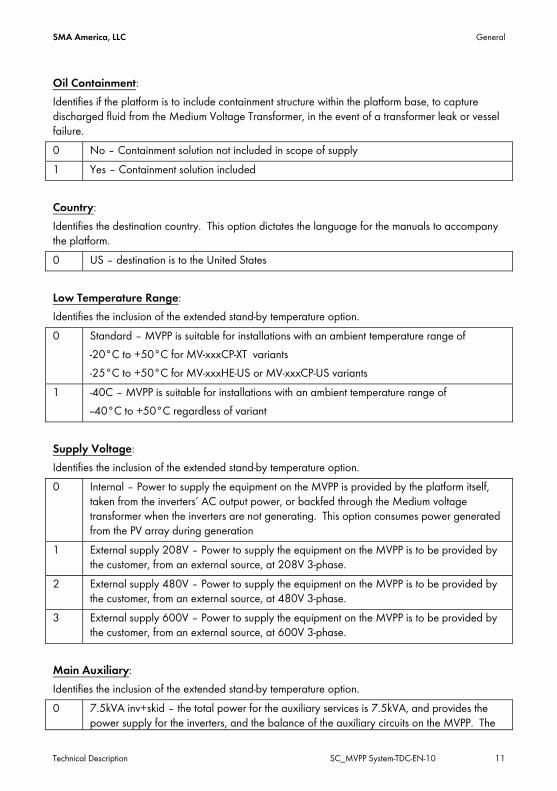
Oil Containment: Identifies if the platform is to include containment structure within the platform base, to capture discharged fluid from the Medium Voltage Transformer, in the event of a transformer leak or vessel failure. 0 No – Containment solution not included in scope of supply 1 Yes – Containment solution included Country: Identifies the destination country. This option dictates the language for the manuals to accompany the platform. 0 US – destination is to the United States Low Temperature Range: Identifies the inclusion of the extended stand-by temperature option. 0 Standard – MVPP is suitable for installations with an ambient temperature range of
-20°C to +50°C for MV-xxxCP-XT variants -25°C to +50°C for MV-xxxHE-US or MV-xxxCP-US variants
1 -40C – MVPP is suitable for installations with an ambient temperature range of --40°C to +50°C regardless of variant
Supply Voltage: Identifies the inclusion of the extended stand-by temperature option. 0 Internal – Power to supply the equipment on the MVPP is provided by the platform itself,
taken from the inverters’ AC output power, or backfed through the Medium voltage transformer when the inverters are not generating. This option consumes power generated from the PV array during generation
1 External supply 208V – Power to supply the equipment on the MVPP is to be provided by the customer, from an external source, at 208V 3-phase.
2 External supply 480V – Power to supply the equipment on the MVPP is to be provided by the customer, from an external source, at 480V 3-phase.
3 External supply 600V – Power to supply the equipment on the MVPP is to be provided by the customer, from an external source, at 600V 3-phase.
Main Auxiliary: Identifies the inclusion of the extended stand-by temperature option. 0 7.5kVA inv+skid – the total power for the auxiliary services is 7.5kVA, and provides the
power supply for the inverters, and the balance of the auxiliary circuits on the MVPP. The
Technical Description SC_MVPP System-TDC-EN-10 11
General SMA America, LLC
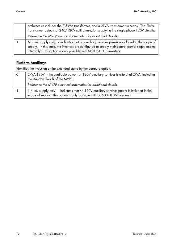
architecture includes the 7.5kVA transformer, and a 2kVA transformer in series. The 2kVA transformer outputs at 240/120V split phase, for supplying the single phase 120V circuits. Reference the MVPP electrical schematics for additional details
1 No (inv supply only) – indicates that no auxiliary services power is included in the scope of supply. In this case, the inverters are configured to supply their control power requirements internally. This option is only possible with SC500-HEUS inverters.
Platform Auxiliary: Identifies the inclusion of the extended stand-by temperature option. 0 2kVA 120V – the available power for 120V auxiliary services is a total of 2kVA, including
the standard loads of the MVPP. Reference the MVPP electrical schematics for additional details
1 No (inv supply only) – indicates that no 120V auxiliary services power is included in the scope of supply. This option is only possible with SC500-HEUS inverters.
12 SC_MVPP System-TDC-EN-10 Technical Description
SMA America, LLC General
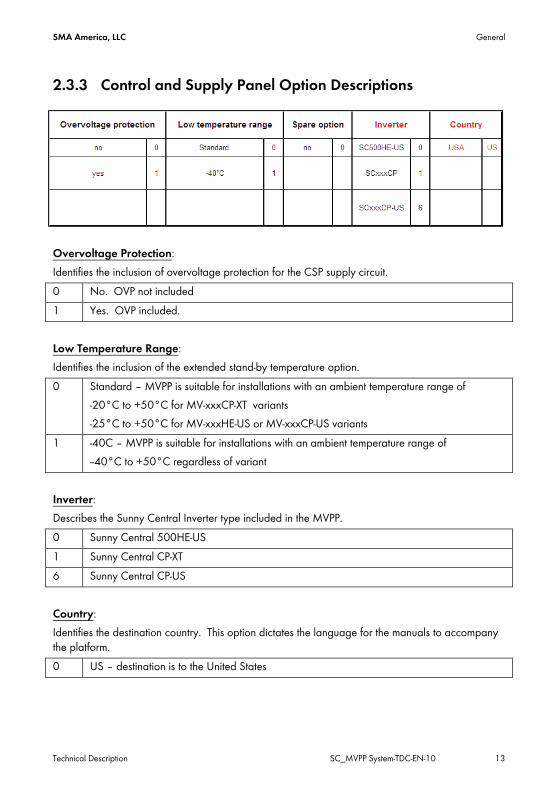
2.3.3 Control and Supply Panel Option Descriptions
Overvoltage Protection: Identifies the inclusion of overvoltage protection for the CSP supply circuit. 0 No. OVP not included 1 Yes. OVP included. Low Temperature Range: Identifies the inclusion of the extended stand-by temperature option. 0 Standard – MVPP is suitable for installations with an ambient temperature range of
-20°C to +50°C for MV-xxxCP-XT variants -25°C to +50°C for MV-xxxHE-US or MV-xxxCP-US variants
1 -40C – MVPP is suitable for installations with an ambient temperature range of --40°C to +50°C regardless of variant
Inverter: Describes the Sunny Central Inverter type included in the MVPP. 0 Sunny Central 500HE-US 1 Sunny Central CP-XT 6 Sunny Central CP-US Country: Identifies the destination country. This option dictates the language for the manuals to accompany the platform. 0 US – destination is to the United States
Technical Description SC_MVPP System-TDC-EN-10 13

General SMA America, LLC
2.3.4 Example Option Code: MVPP Material Number: MV-1500CP-10 MVPP Option Code: 1|1|4|0|US|0|0|0|0 Explanation: MV-1500CP-10 1500kVA power class, including Sunny Central CP-XT inverters. 1 Open platform with an included shade canopy 1 SMA DC Disconnect Unit included 4 Quantity (9) DC inputs for each SMA DC Disconnect Unit 0 Oil containment solution not included US Destination is to the United States 0 Standard ambient temperature range 0 Supply for the MVPP circuits (inverter control power, auxiliary services) is internally derived 0 7.5 kVA main transformer for inverter control power and auxiliary services 0 2 kVA transformer for powering auxiliary services, including those native to the MVPP
14 SC_MVPP System-TDC-EN-10 Technical Description
SMA America, LLC General
2.4 System Description
2.4.1 Scope of Supply The SMA Medium Voltage Power Platform includes the following equipment, which together comprise a complete functioning solution to interface between the array DC home run conductors, and the AC medium voltage collector loop.
i. Steel structural platform ii. SMA Sunny Central Inverters with integrated DC input fuses and AC Disconnecting
means iii. (Optional) DC Disconnect Units iv. Medium Voltage step-up Transformer with integral medium voltage disconnect and
fusing v. Control and Supply Panel vi. Main Auxiliary Supply Transformer vii. Platform Auxiliary Supply Transformer viii. AC power conductors and conduits between the inverters, and low voltage
windings of the Medium Voltage Transformer. ix. Low voltage interface wiring and conduits x. Grounding conductors between included equipment and the grounding bus bar xi. Grounding conductors connecting the grounding bus bar to grounding plates at
opposite corners of the steel base frame. For additional detail, see the MVPP electrical schematics, additional chapters of this document, and the individual Technical Description documents of the Medium Voltage Transformer and Control and Supply Panel.
2.4.2 Exclusions Equipment, Services, and/or accessories not within the scope of supply include:
i. Foundation, foundation design or civil work ii. Site unloading, rigging, and installation iii. Installation tools iv. Canopy installation v. Anchoring provisions and hardware to secure the MVPP to the foundation vi. DC array string combiners, DC input cables, and DC input connection compression
lugs vii. Medium Voltage transformer AC output cables and connection lugs viii. Commissioning ix. Spare parts
Technical Description SC_MVPP System-TDC-EN-10 15
Compliance SMA America, LLC
3 Compliance 3.1 List of Standards The Medium Voltage Power Platforms have been engineered for compliance to the following Norms and Standards.
3.1.1 Platform / System Applicable Standards Standard Description Revision IEEE 1584-2002 Guide for Performing Arc-Flash Hazard Calculations 2002 NFPA 70E Standard for Electrical Safety in the Workplace 2008 NFPA 70 National Electrical Code 2011 NFPA 101 Life Safety Code NFPA 255 Standard Test Method for Surface Burning
Characteristics of Building Materials
NFPA 496 Stanadrd for Purged and Pressurized Enclosures for Electrical Equipment
NESC National Electrical Safety Code 2007 29 CFR Part 1910 Code of Federal Regulations 40 CFR Part 112 Oil Pollution Prevention and Response; Non-
Transportation-Related Onshore and Offshore Facilities; Final Rule
IBC International Building Code 2009 ASCE 7-05 Minimum Design Loads for Buildings and Other
Structures
ASTM A36/A36M Standard Specification for Carbon Structural Steel ASTM A90/A90M Standard Test Method for Weight (Mass) of Coating
on Iron and Steel Articles with Zinc or Zinc Alloy Coatings
ASTM A525 Standard Specifications for General Requirements for Sheet Steel, Zinc Coated (Galvanized) by the Hot Dip Process
ASTM B117 Standard Practice for Operating Salt Spray (Fog) Testing
ASTM D714 Standard Test Method for Evaluating Degree of
16 SC_MVPP System-TDC-EN-10 Technical Description
SMA America, LLC Compliance
Blistering of Paints ASTM D1654 Method for Evaluation of Painted or Coated
Specimens Subjected to Corrosive Environments
ASTM D2244 Standard Practice for Calculation of Color Tolerances and Color Differences from Instrumentally Measured Color Coordinates
ASTM E84-04 Standard Test Method for Surface Burning Characteristics of Building Materials NFPA
AISC 360 Specifications for Structural Steel Buildings ANSI A117.1 Accessible and Usable Facilities and Buildings 2009 ANSI C80.1 Standard for Electrical Rigid Steel Conduit ANSI/SDI 100 Recommended Specification for Standard Steel
Doors and Frames
Fed Spec TT-C-520B Federal Specifications for coating compounds, Bituminous, Solvent Type, Underbody
SSPC Steel Structures Painting Council AWS D1.1 American Welding Society; Structural Welding Code
- Steel
NEMA 250 Enclosures for Electrical Equipment (1000V Maximum)
1997
NETA National Electrical Testing Association 2009 UMC Uniform Mechanical Code 2009 OSHA Occupational Safey and Health Administration
3.1.2 Auxiliary Transformer Applicable Standards Standard Description Revision IEC 62109-1 Safety of Power Converters for use in Photovoltaic
power systems 2010-04
UL 840 Insulation coordination including clearances and creepage distances for electrical equipment
2005-01
IEC 61558-1 Safety of power transformers, power supplies, reactors and similar products – Part 1: General requirements and tests
2009-04
IEC 61558-2-4 Safety of power transformers, power supplies, 2009-02
Technical Description SC_MVPP System-TDC-EN-10 17
Compliance SMA America, LLC
reactors and similar products for volatages up to 1100V – Part 2-4: Particular requirements and tests for isolating transformers and power supply units incorporating isolating transformers
UL 5085-1 Low Voltage Transformers – Part 1: General Requirements
2006-04
UL5085-2 Low Voltage Transformers – Part 2: General Purpose Transformers
2006-04
UL / CSA XPTQ Category listing for General Purpose Transformers UL 50 Enclosures for Electrical Equipment, Non-
Environmental Considerations
cUL Underwriters Laboratories - Cananda product safety standards compliance
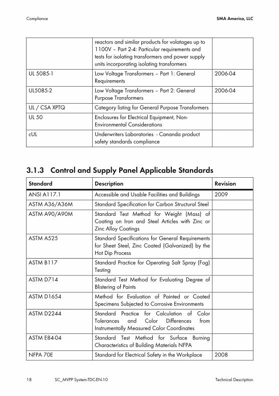
3.1.3 Control and Supply Panel Applicable Standards Standard Description Revision ANSI A117.1 Accessible and Usable Facilities and Buildings 2009 ASTM A36/A36M Standard Specification for Carbon Structural Steel ASTM A90/A90M Standard Test Method for Weight (Mass) of
Coating on Iron and Steel Articles with Zinc or Zinc Alloy Coatings
ASTM A525 Standard Specifications for General Requirements for Sheet Steel, Zinc Coated (Galvanized) by the Hot Dip Process
ASTM B117 Standard Practice for Operating Salt Spray (Fog) Testing
ASTM D714 Standard Test Method for Evaluating Degree of Blistering of Paints
ASTM D1654 Method for Evaluation of Painted or Coated Specimens Subjected to Corrosive Environments
ASTM D2244 Standard Practice for Calculation of Color Tolerances and Color Differences from Instrumentally Measured Color Coordinates
ASTM E84-04 Standard Test Method for Surface Burning Characteristics of Building Materials NFPA
NFPA 70E Standard for Electrical Safety in the Workplace 2008
18 SC_MVPP System-TDC-EN-10 Technical Description
SMA America, LLC Compliance
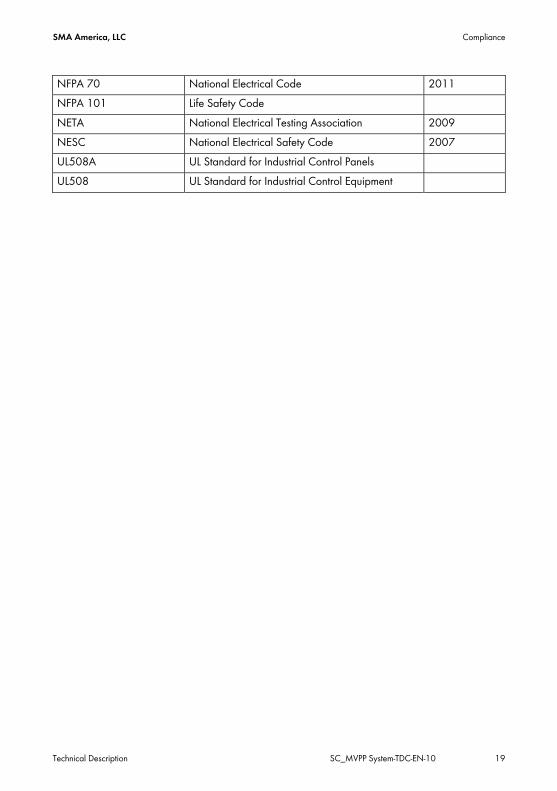
NFPA 70 National Electrical Code 2011 NFPA 101 Life Safety Code NETA National Electrical Testing Association 2009 NESC National Electrical Safety Code 2007 UL508A UL Standard for Industrial Control Panels UL508 UL Standard for Industrial Control Equipment
Technical Description SC_MVPP System-TDC-EN-10 19

MVPP Mechanical Design SMA America, LLC
4 MVPP Mechanical Design 4.1 Design Variants
4.1.1 Open Platform
Item Description
A Main Auxiliary Transformer B Control and Supply Panel C Sunny Central Inverters D SMA DC Disconnect Units (optional) E Medium Voltage Step-Up Transformer
20 SC_MVPP System-TDC-EN-10 Technical Description
SMA America, LLC MVPP Mechanical Design
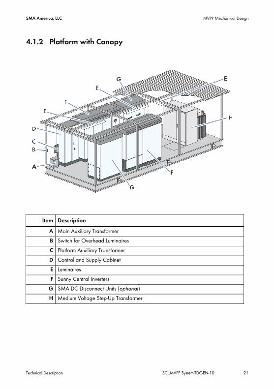
4.1.2 Platform with Canopy
Item Description A Main Auxiliary Transformer B Switch for Overhead Luminaires C Platform Auxiliary Transformer D Control and Supply Cabinet E Luminaires F Sunny Central Inverters
G SMA DC Disconnect Units (optional) H Medium Voltage Step-Up Transformer
Technical Description SC_MVPP System-TDC-EN-10 21
MVPP Mechanical Design SMA America, LLC
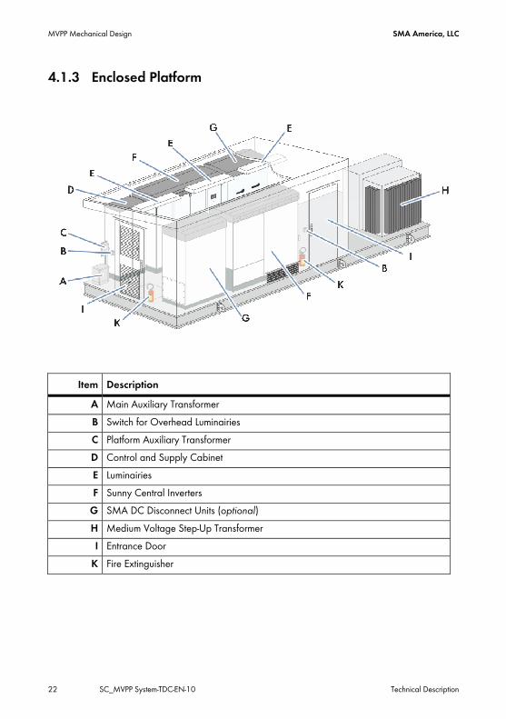
4.1.3 Enclosed Platform
Item Description A Main Auxiliary Transformer B Switch for Overhead Luminairies C Platform Auxiliary Transformer D Control and Supply Cabinet E Luminairies F Sunny Central Inverters
G SMA DC Disconnect Units (optional) H Medium Voltage Step-Up Transformer I Entrance Door
K Fire Extinguisher
22 SC_MVPP System-TDC-EN-10 Technical Description

SMA America, LLC MVPP Mechanical Design
4.2 Materials Item Description Value
1 Steel Platform 15 inch perimeter members, “I” or “C” profile 8 inch cross members, “I” or “C” profile
2 Steel Floor Galvanized sheet steel Anti-slip textured surface treatment
3 Cable Interface Gland Plates Removeable gland plates, galvanized or painted steel plate, and secured with stainless steel hardware
4 Canopy Framing Painted Steel 5 Canopy Roof Corregated Painted Steel 6 Insulation (Enclosed Variant) R6 mineral wool or fiberglass batting.
2 inch thick, minimum Low flammability, non-wicking, asbestos free (Enclosed variants only)
7 Fire Extinguisher (Enclosed Variant)
Qty (2) Carbon Dioxide Extinguishers, minimum 10 lb each, with retainers
8 Lighting (Canopy and Enclosed Variants)
3 x 2 x 32W linear fluorescent Luminairies
9 Light Switches Qty (1) two-way switch mounted to Canopy frame, Qty (2) three way switches located at each entry door (Enclosed variants)
10 Energency Lighting (Enclosed Variant)
Qty (2) LED Emergency Exit Signs with Battery Backup
11 Smoke Detection (Enclosed Variant)
Qty (1) Smoke Detector, 120V, with alarm contacts. One alarm contact factory wired into inverter protection circuit.
12 Touch up paint 1 quart of each color of the MVPP included 13 Egress Qty (1) 4’ x 8’ Steel Door
Qty (1) 3’ x 8’ Steel Door Left hinged, opening outwards. Equipped with exterior door handles, internal crash bars, door closer, and locks (keyed alike) Short side door equipped with air inlet louvers (Enclosed variants only)
Technical Description SC_MVPP System-TDC-EN-10 23
MVPP Mechanical Design SMA America, LLC
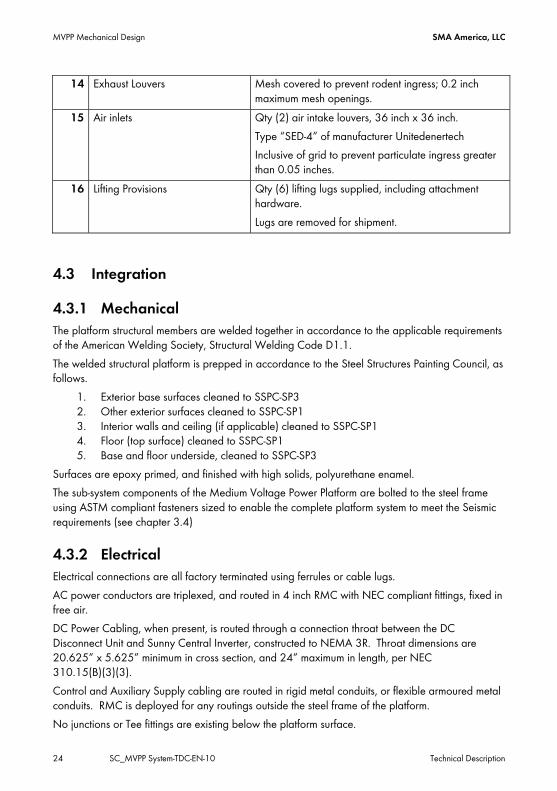
14 Exhaust Louvers Mesh covered to prevent rodent ingress; 0.2 inch maximum mesh openings.
15 Air inlets Qty (2) air intake louvers, 36 inch x 36 inch. Type “SED-4” of manufacturer Unitedenertech Inclusive of grid to prevent particulate ingress greater than 0.05 inches.
16 Lifting Provisions Qty (6) lifting lugs supplied, including attachment hardware. Lugs are removed for shipment.
4.3 Integration
4.3.1 Mechanical The platform structural members are welded together in accordance to the applicable requirements of the American Welding Society, Structural Welding Code D1.1. The welded structural platform is prepped in accordance to the Steel Structures Painting Council, as follows.
1. Exterior base surfaces cleaned to SSPC-SP3 2. Other exterior surfaces cleaned to SSPC-SP1 3. Interior walls and ceiling (if applicable) cleaned to SSPC-SP1 4. Floor (top surface) cleaned to SSPC-SP1 5. Base and floor underside, cleaned to SSPC-SP3
Surfaces are epoxy primed, and finished with high solids, polyurethane enamel. The sub-system components of the Medium Voltage Power Platform are bolted to the steel frame using ASTM compliant fasteners sized to enable the complete platform system to meet the Seismic requirements (see chapter 3.4)
4.3.2 Electrical Electrical connections are all factory terminated using ferrules or cable lugs. AC power conductors are triplexed, and routed in 4 inch RMC with NEC compliant fittings, fixed in free air. DC Power Cabling, when present, is routed through a connection throat between the DC Disconnect Unit and Sunny Central Inverter, constructed to NEMA 3R. Throat dimensions are 20.625” x 5.625” minimum in cross section, and 24” maximum in length, per NEC 310.15(B)(3)(3). Control and Auxiliary Supply cabling are routed in rigid metal conduits, or flexible armoured metal conduits. RMC is deployed for any routings outside the steel frame of the platform. No junctions or Tee fittings are existing below the platform surface.
24 SC_MVPP System-TDC-EN-10 Technical Description

SMA America, LLC MVPP Mechanical Design
Communications cabling, routed in separate dedicated conduits, ½ inch minimum. All pull boxes and conduit penetrations are sealed against ingress of rodents.
4.4 Mechanical and Environmental Data Item Description Value
1 Surface Treatments CSP – RAL 9016 (traffic white) Steelframe and Floor – RAL7005 (mouse grey) Canopy Framework – RAL 9016 (traffic white) Roof Plates – RAL 9016 (traffic white) Enclosure exterior walls – RAL 9016 (traffic white) Enclosure roof – RAL 9016 (traffic white) Surface preparations according to SSPC guidelines Designed for >25 year service lifetime
2 Snow Load < 40 psf (Canopy) < 17 psf (CSP)
3 Wind load < 110 mph 4 Siesmic Zone 4
Site Class D Spectral Acceleration Short Period (Ss) = 2.25g Spectral Acceleration 1 second Periods (S1) = 1.22g Importance Factor = 1
5 Air Consumption 3,532 cfm Pressure drop, inlet, max 10 pa Pressure drop, outlet, max 20 pa
6 Ambient Temperature Range (Operation)
-25°C to +50°C (HEUS and CP-US) -20°C to +50°C (CP-XT)
7 Ambient Temperature Range (Storage)
-40°C to +50°C (with optional Low Temp package)
8 Relative Humidity 0 to 95% non-condensing 9 Max. Altitude 4000m (13,125 feet)
10 UV Resistance All components exposed to Sunlight suitable for continuous, prolonged exposure without fading, color change, corrosion, or deterioration for intended design life.
11 Design Life 25 years
Technical Description SC_MVPP System-TDC-EN-10 25

Electrical Design SMA America, LLC
5 Electrical Design 5.1 System Electrical Overview Item Description
A String Combiner Boxes B DC Contactor (CP-US Inverters) or Load Break Switch (CP-XT Inverters) C Inverter AC Output Circuit Breaker D Inverter Control Power Breaker E Auxiliary Services Supply F Medium Voltage Load Break Switch
G Grid
26 SC_MVPP System-TDC-EN-10 Technical Description

SMA America, LLC Electrical Design
H Inverter 1 Control Power Supply I Inverter 2 Control Power Supply
K Auxiliary Transformer Protective Devices L Auxiliary Loads
M External Supply Voltage (optional) T1 Main Auxiliary Supply Transformer T2 Platform Auxiliary Supply Transformer
AC DC Supply Voltage Supply Voltage (optional)
5.2 Electrical Data
Item Description Value 1 Frequency 60 hertz 2 Supply Voltages Internal Supply: 200V, 270V, 315V, 324V, 342V, 360V
External Supply: 208V, 480V, 600V 3 Main Auxiliary
Transformer 7.5kVA xxxV / 400V (Primary Voltage matched to supply) Dyn5 > 96% efficiency 100% Duty Cycle RAL 9016 (traffic white) NEMA 3R
4 Platform Auxiliary Transformer
2 kVA 400V/240-120V > 96% efficiency 100% Duty Cycle RAL 9016 (traffic white) NEMA 3R
Technical Description SC_MVPP System-TDC-EN-10 27
Electrical Design SMA America, LLC
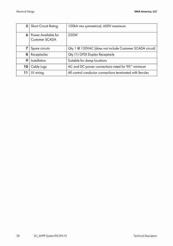
5 Short Circuit Rating 100kA rms symmetrical, 600V maximum
6 Power Available for Customer SCADA
250W
7 Spare circuits Qty 1 @ 120VAC (does not include Customer SCADA circuit) 8 Receptacles Qty (1) GFDI Duplex Receptacle 9 Installation Suitable for damp locations
10 Cable Lugs AC and DC power connections rated for 90° minimum 11 LV wiring All control conductor connections terminated with ferrules
28 SC_MVPP System-TDC-EN-10 Technical Description

SMA America, LLC Control and Supply Panel
6 Control and Supply Panel The Control and Supply Panel provides the low voltage power distribution for platform loads, and customer supplied SCADA (if present). Dedicated space has been allocated within the CSP to enable direct integration of typical SCADA components by the customer.
Item Description A CSP Main Disconnect
Technical Description SC_MVPP System-TDC-EN-10 29

Control and Supply Panel SMA America, LLC
6.1 Space and Supply for Customer Equipment Space H x W x D 34” x 30” x 12” Supply Voltage/Frequency 120 VAC / 60 hz Power Input ≤ 250W Heat losses ≤ 50W Environmental Suitability Ambient Temperature -25°C to +60°C
-13°F to 140°F Relative Humidity 0 – 90% non-condensing
6.2 Components Disclaimer: The components outlined in Chapter 6.3, Chapter 7, and Chapters 10.1.3 and 10.1.4, reflect functional components for the Control & Supply Panel. In all cases, the actual manufacturer and part numbers are subject to change without any notification from SMA. In no scenario does SMA assume liability to provide the exact components as outlined in this chapter. SMA reserves the right to provide functional equivalents in all circumstances, as SMA is committed to continuous improvement and optimization efforts.
6.2.1 Heater against Condensation Ref: circuit diagram Identification “E1” Heating Power 250W Supply Voltage 230VAC / 60hz Mounting 35mm DIN Rail
6.2.2 Hygrostat Ref: circuit diagram Identification “B1” Input Voltage 230VAC / 60hz Operating Temperature 0°C to +60°C Min Setting Range 35 to 95 % r.H.
Set to 80% Mounting 35mm DIN Rail
30 SC_MVPP System-TDC-EN-10 Technical Description
SMA America, LLC Control and Supply Panel
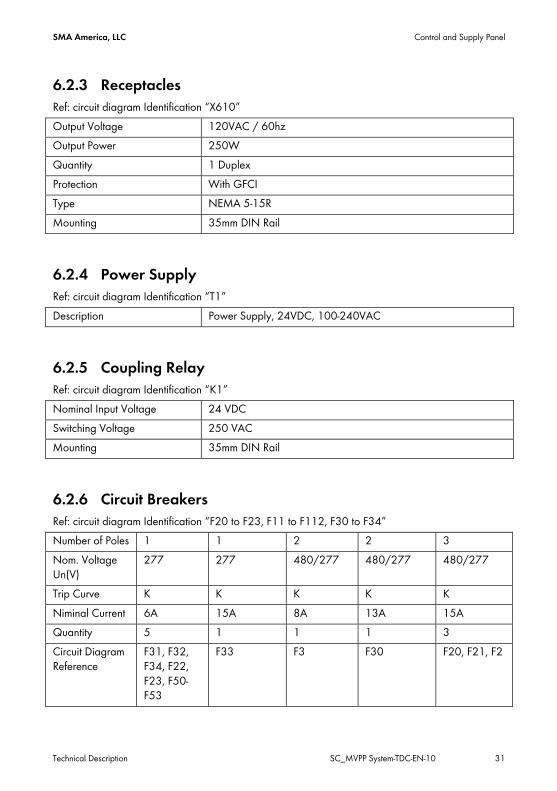
6.2.3 Receptacles Ref: circuit diagram Identification “X610” Output Voltage 120VAC / 60hz Output Power 250W Quantity 1 Duplex Protection With GFCI Type NEMA 5-15R Mounting 35mm DIN Rail
6.2.4 Power Supply Ref: circuit diagram Identification “T1” Description Power Supply, 24VDC, 100-240VAC
6.2.5 Coupling Relay Ref: circuit diagram Identification “K1” Nominal Input Voltage 24 VDC Switching Voltage 250 VAC Mounting 35mm DIN Rail
6.2.6 Circuit Breakers Ref: circuit diagram Identification “F20 to F23, F11 to F112, F30 to F34” Number of Poles 1 1 2 2 3 Nom. Voltage Un(V)
277 277 480/277 480/277 480/277
Trip Curve K K K K K Niminal Current 6A 15A 8A 13A 15A Quantity 5 1 1 1 3 Circuit Diagram Reference
F31, F32, F34, F22, F23, F50-F53
F33 F3 F30 F20, F21, F2
Technical Description SC_MVPP System-TDC-EN-10 31

Control and Supply Panel SMA America, LLC
6.2.7 Fused Disconnect Switch Fuse Type Class J Max Fuse Rating 60A SCCR 200kA Max. Operating Voltage 600 Vac Insulation Suitable for 1450V phase to
Ground
6.2.8 Ethernet pass-through Module Ref: circuit diagram Identification “X500, X501” Description RJ-45 Interface Module
6.2.9 Wire Duct Dimension Width: 1.97“ / 50mm Max Wire Cross Section 4 AWG
6.2.10 Terminal Blocks Manufacturer: Wago www.wago.com Description Wago P/N Min. SCCR 4-Conductor through terminal block 22-12AWG 2002-1401 5kA 3-Conductor through terminal block 20-8 AWG 2006-1301 5kA 3-Conductor earth terminal block 20-8 AWG 2006-1307 5kA 2-Conductor through terminal block 8-2 AWG (X1, X2)
285-635 100kA
2-Conductor earth terminal block 8-2 AWG (X1, X2)
285-637 100kA
Fuse Terminal Block 28-12 AWG 281-611
6.2.11 PE Bus Bar The bus bar is tin-plated copper. If Overvoltage Protection is selected by Option Code, the surge arrestors are mounted to this bus bar.
32 SC_MVPP System-TDC-EN-10 Technical Description
SMA America, LLC Control and Supply Panel
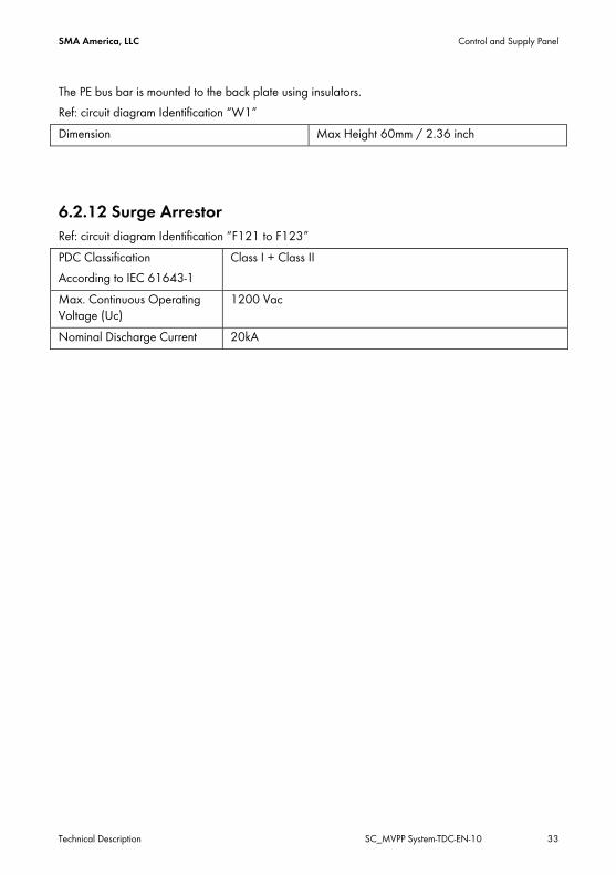
The PE bus bar is mounted to the back plate using insulators. Ref: circuit diagram Identification “W1” Dimension Max Height 60mm / 2.36 inch
6.2.12 Surge Arrestor Ref: circuit diagram Identification “F121 to F123” PDC Classification According to IEC 61643-1
Class I + Class II
Max. Continuous Operating Voltage (Uc)
1200 Vac
Nominal Discharge Current 20kA
Technical Description SC_MVPP System-TDC-EN-10 33
Low Temperature Range (option) SMA America, LLC
7 Low Temperature Range (option) The Low Temperature Range option enables the MVPP to be deployed in environments where the ambient remperature reaches as low as -40°C. This option requires the MVPP to be connected to the grid, or if powered by an external voltage source, to be buffered. The low-temperature range option does not enable operation of the system below the standard operational ambient temperature range. Instead, the option allows for stand-by during such low temperatures. The system will begin generation after the ambient temperature has reached the standard operational temperature.
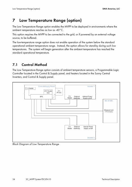
7.1 Control Method The Low Temperature Range option consists of ambient temperature sensors, a Progammable Logic Controller located in the Control & Supply panel, and heaters located in the Sunny Central Inverters, and Control & Supply panel.
Block Diagram of Low Temperature Range
34 SC_MVPP System-TDC-EN-10 Technical Description
SMA America, LLC Low Temperature Range (option)
The basic sequence of the control methodology is: 1. The ambient temperature sensors detect that the ambient temperature is approaching the
lower limit of system operation. 2. The PLC commands the inverters to stop. 3. The Inverters provide confirmation feedback to the PLC that they have stopped. 4. The presence of voltage at the Medium Voltage Transformer’s low voltage terminals is
confirmed by digital input to the PLC. 5. The PLC disconnects the Control & Supply Panel’s auxiliary circuits. This means, the full
7.5kVA of the Main Auxiliary Supply transformer is available for consumption by the Low Temperature Range option.
6. The heaters are switched on, and maintain a temperature inside the inverters, and Control and Supply cabinet, above the lower threshold of operation. The temperature is dynamically maintained; minimizing the consumption based on the ambient temperature.
7. The PLC sends a digital output, indicating that the low temperature range heating is started. (optional)
8. The ambient temperature rises to approximately -17°C, considering the inbuilt hysteresis loop.
9. The PLC sends a digital output, indicating that the low temperature range heating is stopping. (optional)
10. The auxiliary power circuits are reconnected. 11. The PLC commands the inverters to start up. 12. The inverters connect to the grid through their normal start up sequence, and begin
feeding in to the grid.
Technical Description SC_MVPP System-TDC-EN-10 35
Oil Containment (option) SMA America, LLC
8 Oil Containment (option) The MVPP can be configured to include a built-in spill containment vessel to prevent any transformer fluid from escaping the platform in the event of a leak or failure. The vessel is contained within the platform structure. The spill containment option is designed to enable a customer to easily comply to the requirements of 40 CRF 112, if their specific project circumstances dictates spill containment. It provides enough containment volume to hold the total fluid from the transformer, plus additional freeboard for consideration of precipitation. The actual volume of containment is dependent upon the configuration of the platform variant. The containment option design,
1. Must be sized to hold the total available fluid from the transformer, plus the maximum precipitation on record in a 24 hr period for the project site.
2. Shall have a sloped bottom, to enable the exit of fluid from the discharge location (drain).
3. Shall have access to the vessel for maintenance or cleaning, such as removal of debris from the drain location. For example, to remove fallen leaves or windblown debris.
4. Shall include provisions in concert with the vessel, to physically prevent fluid from escaping the path to the vessel, such as a perimeter curb or berm.
The discharge from the vessel, 1. Must be located such thar access is enabled after platform installation. 2. Shall be through a “petro-pipe” oile/water separating valve, an dpre-filter, such that
rainwater can pass freely out of the drain, while mineral oil and alternative transformer cooling fluids, cannot exit the discharge. The oil/water separating valve must be of UV resistant material.
3. A screen over the discharge shall be provided to prevent entry of medium size debris, such as leaves or other wind-blown debris.
All materials for connecting the discharge pipe to the pre-filter and “petro-pipe” are included, and are of galvanized pipe. No PVC pipe or fittings are used. When the oil containment option is selected, the floor of the platform surrounding the medium-vltage transformer shall be pf a perforated or “grate” material, such that any possible fluid discharged is captured within the containment vessel. The material of the grate and/or surface treatment, provides for a design life of 25 years, without requiring additional maintenance procedures beyond that of the standard floor surface treatment. Where applicable, all components are UL listed or recognized.
36 SC_MVPP System-TDC-EN-10 Technical Description

SMA America, LLC Oil Containment (option)
8.1 Example of Oil Containment
Technical Description SC_MVPP System-TDC-EN-10 37

Routine Testing SMA America, LLC
9 Routine Testing In addition to robust design type tests, every Medium Voltage Power Platform undergoes end-of-line production testing. These tests include:
9.1 Medium Voltage Power Platform Item Test
1 Visual Inspections 2 Dielectric Voltage Withstand Test 3 Continuity 4 Function Test 5 Torque Test
9.2 Control and Supply Panel Item Test
1 Visual Inspections 2 Function Test 3 Voltage test (transformer tap verification) 4 Dielectric Voltage Withstand Test 5 Ground Fault Protection (per UL508A) 6 Overload Test (per UL508) 7 Endurance Test (per UL508) 8 Torque Test
38 SC_MVPP System-TDC-EN-10 Technical Description

SMA America, LLC Appendix
Technical Description SC_MVPP System-TDC-EN-10 39
10 Appendix 10.1 Power Conductor Sizes
10.1.1 AC Conductors Inverter SC500HEUS SC500CP-XT
SC500CP-US SC630CP-XT SC630CP-US
SC800/760/720CP-XT SC800/750/720CP-US
Cable DLO* DLO* DLO* DLO* # per phase 5 x 444kcmil 4 x 444kcmil 4 x 444kcmil 4 x 535kcmil Conduit 4 x 4in 4 x 4in 4 x 4in 4 x 4in * DLO, UL RHH/RHW-2 2kV for operation in 90°C wet and dry locations
10.1.2 DC Conductors Inverter SC500HEUS SC500CP-XT
SC500CP-US SC630CP-XT SC630CP-US
SC800/760/720CP-XT SC800/750/720CP-US
Cables DLO* DLO* DLO* DLO* # per DC input
2 x 3/0 AWG Or 1 x 646kcmil
2 x 3/0 AWG Or 1 x 646kcmil
2 x 3/0 AWG Or 1 x 646kcmil
2 x 3/0 AWG Or 1 x 646kcmil
* DLO, UL RHH/RHW-2 2kV for operation in 90°C wet and dry locations

11 Contact If you have technical problems with our products, please contact our Serviceline. We require the following information in order to provide you with the necessary assistance:
• Inverter type • Serial number of the Sunny Central • Type and number of modules connected • Event number or display message of the Sunny Central • Type of communication, if applicable • Type of fault signaling contact connected, if applicable
SMA Solar Technology America, LLC 6020 West Oaks Blvd, Ste 300 Rocklin, CA 95765 Tel. +1 916 625 0870 Tel. +1 877-MY SMA TECH Tel. +1 877 697 6283 (Toll free, available for USA, Canada and Puerto Rico) Fax +1 916 625 0871 [email protected] www.SMA-America.com
SMA Solar Technology Canada Inc. 2425 Matheson Blvd, 8th Floor Mississauga, ON L4W 5K5, Canada Tel. +1 877 506 1756 (Toll free, available for Canada) [email protected] www.SMA-Canada.ca
SMA Solar Technology
www.SMA-Solar.com
SMA America, LLC www.SMA-America.com


![[XLS]mail. · Web view1 15774. 2 15775. 3 22438. 4 15777. 5 15778. 6 15779. 7 15780. 8 15781. 9 15782. 10 15783. 11 15784. 12 15785. 13 15786. 14 15787.](https://static.fdocuments.us/doc/165x107/5ab110787f8b9a284c8bff70/xlsmail-view1-15774-2-15775-3-22438-4-15777-5-15778-6-15779-7-15780-8.jpg)


![arXiv:1310.5353v1 [hep-ph] 20 Oct 2013 · arXiv:1310.5353v1 [hep-ph] 20 Oct 2013 Preprint typeset in JHEP style - PAPER VERSION SLAC–PUB–15775 Abriefintroductiontomodern amplitudemethods](https://static.fdocuments.us/doc/165x107/5f6ae9a4a6f9b6434424372b/arxiv13105353v1-hep-ph-20-oct-2013-arxiv13105353v1-hep-ph-20-oct-2013-preprint.jpg)