SMA CLUSTER CONTROLLER - Installation...
84
ClusterController-IA-en-10 | Version 1.0 EN Device for Monitoring and Controlling SMA Inverters in Decentralised Large-Scale PV Plants SMA CLUSTER CONTROLLER Installation Manual
Transcript of SMA CLUSTER CONTROLLER - Installation...

ClusterController-IA-en-10 | Version 1.0 EN
Device for Monitoring and Controlling SMA Inverters in Decentralised Large-Scale PV PlantsSMA CLUSTER CONTROLLERInstallation Manual

SMA Solar Technology AG Table of Contents
Installation Manual ClusterController-IA-en-10 3
Table of Contents1 Information on this Document. . . . . . . . . . . . . . . . . . . . . . . . . . . 62 Safety . . . . . . . . . . . . . . . . . . . . . . . . . . . . . . . . . . . . . . . . . . . . . . 8
2.1 Intended Use . . . . . . . . . . . . . . . . . . . . . . . . . . . . . . . . . . . . . . . . . . . . 82.2 Qualifications of Skilled Persons . . . . . . . . . . . . . . . . . . . . . . . . . . . . 102.3 Safety Precautions . . . . . . . . . . . . . . . . . . . . . . . . . . . . . . . . . . . . . . . 10
3 Scope of Delivery . . . . . . . . . . . . . . . . . . . . . . . . . . . . . . . . . . . . 114 Product Description . . . . . . . . . . . . . . . . . . . . . . . . . . . . . . . . . . 12
4.1 Cluster Controller. . . . . . . . . . . . . . . . . . . . . . . . . . . . . . . . . . . . . . . . 124.2 Type Label . . . . . . . . . . . . . . . . . . . . . . . . . . . . . . . . . . . . . . . . . . . . . 164.3 LEDs . . . . . . . . . . . . . . . . . . . . . . . . . . . . . . . . . . . . . . . . . . . . . . . . . . 174.4 Display. . . . . . . . . . . . . . . . . . . . . . . . . . . . . . . . . . . . . . . . . . . . . . . . 184.5 Button Field . . . . . . . . . . . . . . . . . . . . . . . . . . . . . . . . . . . . . . . . . . . . 204.6 System Requirements of the Computer . . . . . . . . . . . . . . . . . . . . . . . 20
5 Assembly. . . . . . . . . . . . . . . . . . . . . . . . . . . . . . . . . . . . . . . . . . . 215.1 Selecting the Mounting Location . . . . . . . . . . . . . . . . . . . . . . . . . . . . 215.2 Mounting the Cluster Controller. . . . . . . . . . . . . . . . . . . . . . . . . . . . . 23
6 Connection . . . . . . . . . . . . . . . . . . . . . . . . . . . . . . . . . . . . . . . . . 246.1 Overview of the Connection Area . . . . . . . . . . . . . . . . . . . . . . . . . . . 246.2 Functions of the Terminals and Terminal Blocks . . . . . . . . . . . . . . . . . 256.3 Cable Requirements. . . . . . . . . . . . . . . . . . . . . . . . . . . . . . . . . . . . . . 276.4 Performing Pin Coding . . . . . . . . . . . . . . . . . . . . . . . . . . . . . . . . . . . . 296.5 Preparing Connection Cables for Connection to a Multipole Plug . . 306.6 Connecting the Cluster Controller to a Speedwire Network . . . . . . . 326.7 Connecting the Cluster Controller to a Local Area Network (LAN). . 346.8 Setting Up a Modbus Data Connection . . . . . . . . . . . . . . . . . . . . . . 356.9 Connecting USB Data Carriers to the Cluster Controller . . . . . . . . . . 35
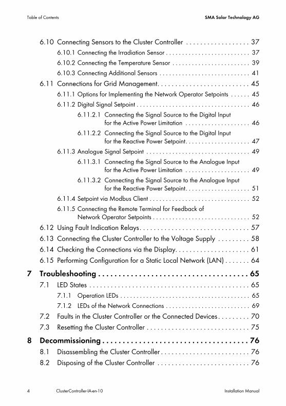
Table of Contents SMA Solar Technology AG
4 ClusterController-IA-en-10 Installation Manual
6.10 Connecting Sensors to the Cluster Controller . . . . . . . . . . . . . . . . . . 376.10.1 Connecting the Irradiation Sensor . . . . . . . . . . . . . . . . . . . . . . . . . . 376.10.2 Connecting the Temperature Sensor . . . . . . . . . . . . . . . . . . . . . . . . 396.10.3 Connecting Additional Sensors . . . . . . . . . . . . . . . . . . . . . . . . . . . . 41
6.11 Connections for Grid Management. . . . . . . . . . . . . . . . . . . . . . . . . . 456.11.1 Options for Implementing the Network Operator Setpoints . . . . . . 456.11.2 Digital Signal Setpoint . . . . . . . . . . . . . . . . . . . . . . . . . . . . . . . . . . . 46
6.11.2.1 Connecting the Signal Source to the Digital Input for the Active Power Limitation . . . . . . . . . . . . . . . . . . . . 46
6.11.2.2 Connecting the Signal Source to the Digital Input for the Reactive Power Setpoint. . . . . . . . . . . . . . . . . . . . 47
6.11.3 Analogue Signal Setpoint . . . . . . . . . . . . . . . . . . . . . . . . . . . . . . . . 496.11.3.1 Connecting the Signal Source to the Analogue Input
for the Active Power Limitation . . . . . . . . . . . . . . . . . . . . 496.11.3.2 Connecting the Signal Source to the Analogue Input
for the Reactive Power Setpoint. . . . . . . . . . . . . . . . . . . . 516.11.4 Setpoint via Modbus Client . . . . . . . . . . . . . . . . . . . . . . . . . . . . . . . 526.11.5 Connecting the Remote Terminal for Feedback of
Network Operator Setpoints . . . . . . . . . . . . . . . . . . . . . . . . . . . . . . 526.12 Using Fault Indication Relays. . . . . . . . . . . . . . . . . . . . . . . . . . . . . . . 576.13 Connecting the Cluster Controller to the Voltage Supply . . . . . . . . . 586.14 Checking the Connections via the Display. . . . . . . . . . . . . . . . . . . . . 616.15 Performing Configuration for a Static Local Network (LAN) . . . . . . . 64
7 Troubleshooting . . . . . . . . . . . . . . . . . . . . . . . . . . . . . . . . . . . . . 657.1 LED States . . . . . . . . . . . . . . . . . . . . . . . . . . . . . . . . . . . . . . . . . . . . . 65
7.1.1 Operation LEDs . . . . . . . . . . . . . . . . . . . . . . . . . . . . . . . . . . . . . . . . 657.1.2 LEDs of the Network Connections . . . . . . . . . . . . . . . . . . . . . . . . . . 69
7.2 Faults in the Cluster Controller or the Connected Devices . . . . . . . . . 707.3 Resetting the Cluster Controller . . . . . . . . . . . . . . . . . . . . . . . . . . . . . 75
8 Decommissioning . . . . . . . . . . . . . . . . . . . . . . . . . . . . . . . . . . . . 768.1 Disassembling the Cluster Controller . . . . . . . . . . . . . . . . . . . . . . . . . 768.2 Disposing of the Cluster Controller . . . . . . . . . . . . . . . . . . . . . . . . . . 76
SMA Solar Technology AG Table of Contents
Installation Manual ClusterController-IA-en-10 5
9 Technical Data . . . . . . . . . . . . . . . . . . . . . . . . . . . . . . . . . . . . . . 7710 Accessories . . . . . . . . . . . . . . . . . . . . . . . . . . . . . . . . . . . . . . . . . 8111 Contact . . . . . . . . . . . . . . . . . . . . . . . . . . . . . . . . . . . . . . . . . . . . 82
1 Information on this Document SMA Solar Technology AG
6 ClusterController-IA-en-10 Installation Manual
1 Information on this DocumentValidityThis document is applicable for the device type "CLCON-10.GR1" from hardware version A1 and from firmware version 1.0.
Target GroupThis document is intended for skilled persons. Only qualified personnel are allowed to perform the tasks described in this manual (see Section 2.2 "Qualifications of Skilled Persons", page 10).
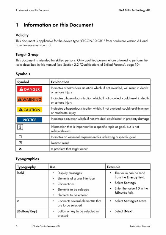
Symbols
Typographies
Symbol ExplanationIndicates a hazardous situation which, if not avoided, will result in death or serious injuryIndicates a hazardous situation which, if not avoided, could result in death or serious injuryIndicates a hazardous situation which, if not avoided, could result in minor or moderate injuryIndicates a situation which, if not avoided, could result in property damage
Information that is important for a specific topic or goal, but is not safety-relevant
☐ Indicates an essential requirement for achieving a specific goal☑ Desired result✖ A problem that might occur
Typography Use Examplebold • Display messages
• Elements of a user interface• Connections• Elements to be selected• Elements to be entered
• The value can be read from the Energy field.
• Select Settings.• Enter the value 10 in the
Minutes field.
> • Connects several element0s that are to be selected
• Select Settings > Date.
[Button/Key] • Button or key to be selected or pressed
• Select [Next].
SMA Solar Technology AG 1 Information on this Document
Installation Manual ClusterController-IA-en-10 7
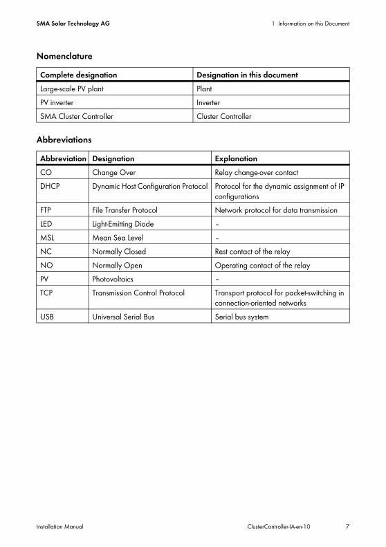
Nomenclature
Abbreviations
Complete designation Designation in this documentLarge-scale PV plant PlantPV inverter InverterSMA Cluster Controller Cluster Controller
Abbreviation Designation ExplanationCO Change Over Relay change-over contact DHCP Dynamic Host Configuration Protocol Protocol for the dynamic assignment of IP
configurations FTP File Transfer Protocol Network protocol for data transmission LED Light-Emitting Diode ‒MSL Mean Sea Level ‒NC Normally Closed Rest contact of the relay NO Normally Open Operating contact of the relay PV Photovoltaics ‒TCP Transmission Control Protocol Transport protocol for packet-switching in
connection-oriented networks USB Universal Serial Bus Serial bus system
2 Safety SMA Solar Technology AG
8 ClusterController-IA-en-10 Installation Manual
2 Safety2.1 Intended UseThe Cluster Controller is a device for monitoring and controlling up to 75 SMA inverters in decentralised large-scale PV plants. For this purpose, the Cluster Controller performs the following essential tasks:
• Reading out, provision and administration of plant data• Configuring device parameters• Sending e-mail alerts in the event of critical plant statuses• Implementation and feedback of network operator setpoints for active power limitation and
reactive power under grid management• Sending the plant data to an FTP server and/or the Sunny Portal Internet portal• Performing updates for the Cluster Controller and the inverters
The Cluster Controller is an ITE Class A device according to EN 55022 and is designed for industrial use.The Cluster Controller is suitable for indoor use only.The Cluster Controller must only be used with supported devices.For safety reasons, it is not permitted to modify the product or install components that are not explicitly recommended or distributed by SMA Solar Technology AG for this product.The enclosed documentation is an integral part of this product:
• Read and observe the documentation.• Keep the documentation in a convenient place for future reference.
Only use the Cluster Controller in accordance with the information provided in the enclosed documentation. Any other use may result in personal injury or property damage.
SMA Solar Technology AG 2 Safety
Installation Manual ClusterController-IA-en-10 9
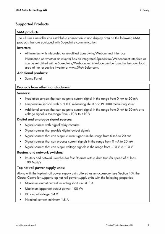
Supported ProductsSMA productsThe Cluster Controller can establish a connection to and display data on the following SMA products that are equipped with Speedwire communication:Inverters:
• All inverters with integrated or retrofitted Speedwire/Webconnect interfaceInformation on whether an inverter has an integrated Speedwire/Webconnect interface or can be retrofitted with a Speedwire/Webconnect interface can be found in the download area of the respective inverter at www.SMA-Solar.com.
Additional products:• Sunny Portal
Products from other manufacturersSensors:
• Irradiation sensors that can output a current signal in the range from 0 mA to 20 mA• Temperature sensors with a PT100 measuring shunt or a PT1000 measuring shunt• Additional sensors that can output a current signal in the range from 0 mA to 20 mA or a
voltage signal in the range from ‒10 V to +10 VDigital and analogue signal sources:
• Signal sources with digital relay contacts• Signal sources that provide digital output signals• Signal sources that can output current signals in the range from 0 mA to 20 mA• Signal sources that can process current signals in the range from 0 mA to 20 mA• Signal sources that can output voltage signals in the range from ‒10 V to +10 V
Routers and network switches:• Routers and network switches for fast Ethernet with a data transfer speed of at least
100 Mbit/sTop-hat rail power supply units:Along with the top-hat rail power supply units offered as an accessory (see Section 10), the Cluster Controller supports top-hat rail power supply units with the following properties:
• Maximum output current including short circuit: 8 A• Maximum apparent output power: 100 VA• DC output voltage: 24 V• Nominal current: minimum 1.8 A
2 Safety SMA Solar Technology AG
10 ClusterController-IA-en-10 Installation Manual
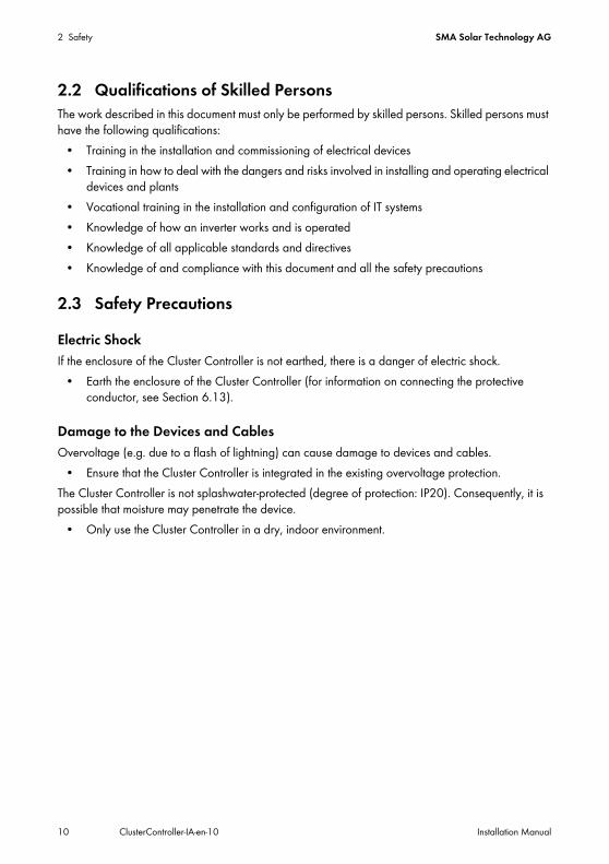
2.2 Qualifications of Skilled PersonsThe work described in this document must only be performed by skilled persons. Skilled persons must have the following qualifications:
• Training in the installation and commissioning of electrical devices• Training in how to deal with the dangers and risks involved in installing and operating electrical
devices and plants• Vocational training in the installation and configuration of IT systems• Knowledge of how an inverter works and is operated• Knowledge of all applicable standards and directives• Knowledge of and compliance with this document and all the safety precautions
2.3 Safety PrecautionsElectric ShockIf the enclosure of the Cluster Controller is not earthed, there is a danger of electric shock.
• Earth the enclosure of the Cluster Controller (for information on connecting the protective conductor, see Section 6.13).
Damage to the Devices and CablesOvervoltage (e.g. due to a flash of lightning) can cause damage to devices and cables.
• Ensure that the Cluster Controller is integrated in the existing overvoltage protection.The Cluster Controller is not splashwater-protected (degree of protection: IP20). Consequently, it is possible that moisture may penetrate the device.
• Only use the Cluster Controller in a dry, indoor environment.
SMA Solar Technology AG 3 Scope of Delivery
Installation Manual ClusterController-IA-en-10 11
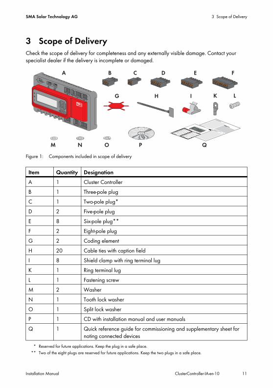
3 Scope of DeliveryCheck the scope of delivery for completeness and any externally visible damage. Contact your specialist dealer if the delivery is incomplete or damaged.
Figure 1: Components included in scope of delivery
Item Quantity DesignationA 1 Cluster ControllerB 1 Three-pole plugC 1 Two-pole plug*
* Reserved for future applications. Keep the plug in a safe place.
D 2 Five-pole plugE 8 Six-pole plug**
** Two of the eight plugs are reserved for future applications. Keep the two plugs in a safe place.
F 2 Eight-pole plugG 2 Coding elementH 20 Cable ties with caption fieldI 8 Shield clamp with ring terminal lugK 1 Ring terminal lugL 1 Fastening screwM 2 WasherN 1 Tooth lock washerO 1 Split lock washerP 1 CD with installation manual and user manualsQ 1 Quick reference guide for commissioning and supplementary sheet for
noting connected devices
4 Product Description SMA Solar Technology AG
12 ClusterController-IA-en-10 Installation Manual
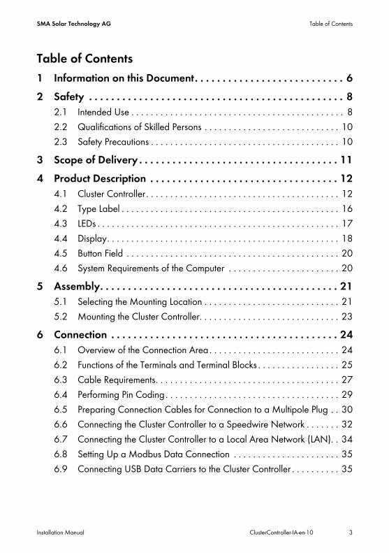
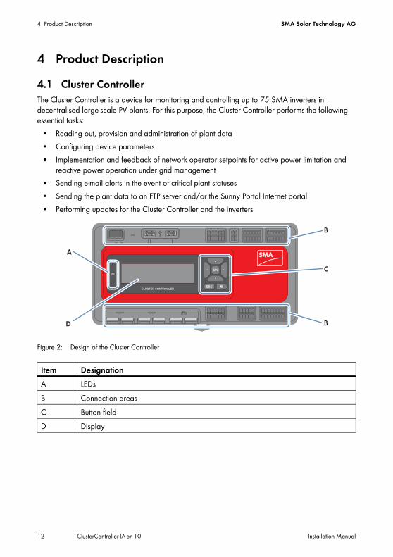
4 Product Description4.1 Cluster ControllerThe Cluster Controller is a device for monitoring and controlling up to 75 SMA inverters in decentralised large-scale PV plants. For this purpose, the Cluster Controller performs the following essential tasks:
• Reading out, provision and administration of plant data• Configuring device parameters• Implementation and feedback of network operator setpoints for active power limitation and
reactive power operation under grid management• Sending e-mail alerts in the event of critical plant statuses• Sending the plant data to an FTP server and/or the Sunny Portal Internet portal• Performing updates for the Cluster Controller and the inverters
Figure 2: Design of the Cluster Controller
Item DesignationA LEDsB Connection areasC Button fieldD Display

SMA Solar Technology AG 4 Product Description
Installation Manual ClusterController-IA-en-10 13
Reading out, Provision and Administration of Plant DataThe Cluster Controller is the central communication unit for the plant and continuously reads out the data of the devices in the plant (e.g. inverters, sensors). The Cluster Controller then makes this plant data available via the display, user interface and Modbus®* data interface. In addition, the plant data can be displayed, evaluated and managed using Sunny Portal (see the Cluster Controller user manual and the user manual of the Cluster Controller in Sunny Portal).
Configuring Device ParametersYou can configure specific parameters of individual devices or entire device classes via the user interface of the Cluster Controller. For this purpose, you must be logged into the Installer user group on the Cluster Controller. The device parameters that can be configured, if any, depend on the device and the rights of the user group. You may only change grid-sensitive device parameters (SMA Grid Guard parameters) with the approval of the network operator and using your personal SMA Grid Guard code (see the Cluster Controller user manual).
Sending E-Mail Alerts in the Event of Critical Plant StatusesYou have the option of receiving prompt information on critical plant statuses via e-mail (see the Cluster Controller user manual). The Cluster Controller automatically sends a notification if alert-related events occur in the plant.
Implementation and Feedback of Network Operator Setpoints for Active Power Limitation and Reactive Power Operation under Grid ManagementWith the Cluster Controller, you can implement different network operator setpoints for the active power limitation and the reactive power operation of your plant under grid management. Your network operator transmits the setpoints directly to the Cluster Controller, either in the form of digital or analogue signals (e.g. to a ripple control receiver that is connected to the Cluster Controller) or via the Modbus client. In agreement with your network operator, you can use the user interface of the Cluster Controller to configure which setpoints of the Cluster Controller are to be transmitted to the connected inverters depending on the respective signal. In addition, you have the option of using a digital response contact or an analogue current output signal to inform the network operator of the setpoints (if any) for the active power limitation and the reactive power operation that are currently being transmitted to the plant.
Sending the Plant Data to an FTP Server and/or the Sunny Portal Internet PortalThe Cluster Controller can automatically send the plant data that has been read out to an arbitrary FTP server and/or the Sunny Portal Internet portal via the Internet. The Cluster Controller establishes the connection to the FTP server and/or the Sunny Portal e.g. via a router.
* Modbus® is a registered trademark of Schneider Electric and is licensed through Modbus Organization, Inc.
4 Product Description SMA Solar Technology AG
14 ClusterController-IA-en-10 Installation Manual
Performing Updates for the Cluster Controller and the InvertersYou have the option of performing updates for the Cluster Controller and the inverters in the plant (see the Cluster Controller user manual). You can perform the updates automatically or manually. The update source can be the SMA update portal or a USB data carrier with update files downloaded from the Internet. Alternatively, you can also upload the update files directly from the computer via the user interface of the Cluster Controller.
SMA Solar Technology AG 4 Product Description
Installation Manual ClusterController-IA-en-10 15
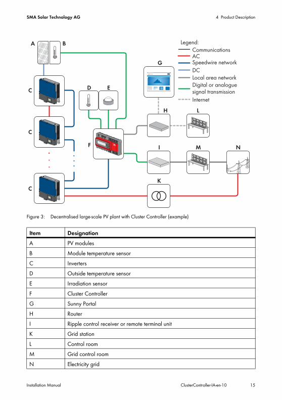
Figure 3: Decentralised large-scale PV plant with Cluster Controller (example)
Item DesignationA PV modulesB Module temperature sensorC InvertersD Outside temperature sensorE Irradiation sensorF Cluster ControllerG Sunny PortalH RouterI Ripple control receiver or remote terminal unitK Grid stationL Control roomM Grid control roomN Electricity grid
4 Product Description SMA Solar Technology AG
16 ClusterController-IA-en-10 Installation Manual
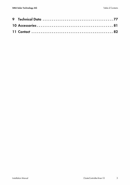
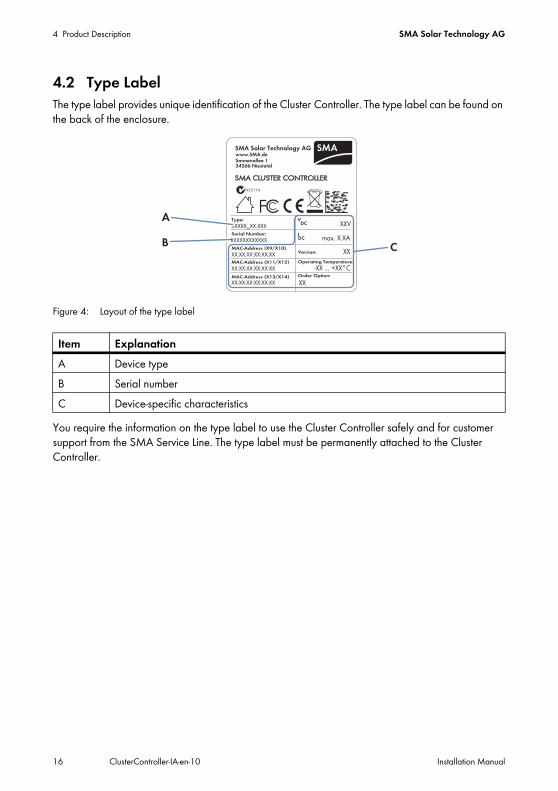
4.2 Type LabelThe type label provides unique identification of the Cluster Controller. The type label can be found on the back of the enclosure.
Figure 4: Layout of the type label
You require the information on the type label to use the Cluster Controller safely and for customer support from the SMA Service Line. The type label must be permanently attached to the Cluster Controller.
Item ExplanationA Device typeB Serial numberC Device-specific characteristics
SMA Solar Technology AG 4 Product Description
Installation Manual ClusterController-IA-en-10 17
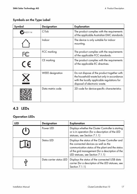
Symbols on the Type Label
4.3 LEDsOperation LEDs
Symbol Designation ExplanationC-Tick The product complies with the requirements
of the applicable Australian EMC standards.Indoor The device is only suitable for indoor
mounting.
FCC marking The product complies with the requirements of the applicable FCC standards.
CE marking The product complies with the requirements of the applicable EC directives.
WEEE designation Do not dispose of the product together with the household waste but only in accordance with the locally applicable regulations for disposal of electronic waste.
Data matrix code 2D code for device-specific characteristics
LED Designation ExplanationPower LED Displays whether the Cluster Controller is starting
or is in operation (for a description of the LED statuses, see Section 7.1.1)
Status LED Displays the status of the Cluster Controller and the connected devices as well as the communication status of the plant and the status of the grid management (for a description of the LED statuses, see Section 7.1.1)
Data carrier status LED Displays the status of the connected USB data carrier (for a description of the LED statuses, see Section 7.1.1)
4 Product Description SMA Solar Technology AG
18 ClusterController-IA-en-10 Installation Manual
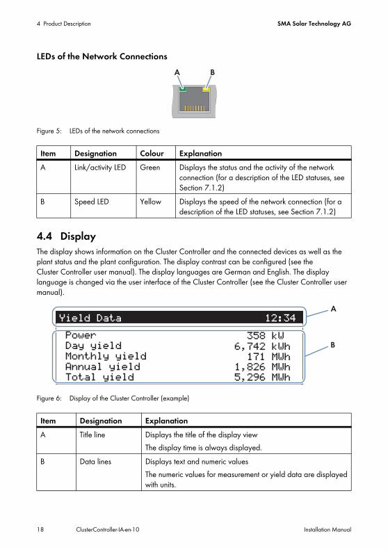
LEDs of the Network Connections
Figure 5: LEDs of the network connections
4.4 DisplayThe display shows information on the Cluster Controller and the connected devices as well as the plant status and the plant configuration. The display contrast can be configured (see the Cluster Controller user manual). The display languages are German and English. The display language is changed via the user interface of the Cluster Controller (see the Cluster Controller user manual).
Figure 6: Display of the Cluster Controller (example)
Item Designation Colour ExplanationA Link/activity LED Green Displays the status and the activity of the network
connection (for a description of the LED statuses, see Section 7.1.2)
B Speed LED Yellow Displays the speed of the network connection (for a description of the LED statuses, see Section 7.1.2)
Item Designation ExplanationA Title line Displays the title of the display view
The display time is always displayed.B Data lines Displays text and numeric values
The numeric values for measurement or yield data are displayed with units.
SMA Solar Technology AG 4 Product Description
Installation Manual ClusterController-IA-en-10 19
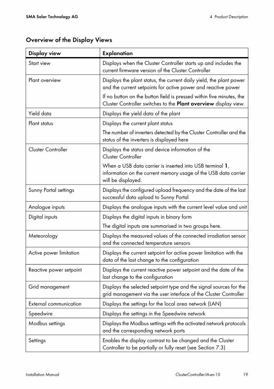
Overview of the Display ViewsDisplay view ExplanationStart view Displays when the Cluster Controller starts up and includes the
current firmware version of the Cluster ControllerPlant overview Displays the plant status, the current daily yield, the plant power
and the current setpoints for active power and reactive powerIf no button on the button field is pressed within five minutes, the Cluster Controller switches to the Plant overview display view.
Yield data Displays the yield data of the plantPlant status Displays the current plant status
The number of inverters detected by the Cluster Controller and the status of the inverters is displayed here
Cluster Controller Displays the status and device information of the Cluster ControllerWhen a USB data carrier is inserted into USB terminal 1, information on the current memory usage of the USB data carrier will be displayed.
Sunny Portal settings Displays the configured upload frequency and the date of the last successful data upload to Sunny Portal
Analogue inputs Displays the analogue inputs with the current level value and unitDigital inputs Displays the digital inputs in binary form
The digital inputs are summarised in two groups here.Meteorology Displays the measured values of the connected irradiation sensor
and the connected temperature sensorsActive power limitation Displays the current setpoint for active power limitation with the
data of the last change to the configurationReactive power setpoint Displays the current reactive power setpoint and the date of the
last change to the configurationGrid management Displays the selected setpoint type and the signal sources for the
grid management via the user interface of the Cluster ControllerExternal communication Displays the settings for the local area network (LAN)Speedwire Displays the settings in the Speedwire networkModbus settings Displays the Modbus settings with the activated network protocols
and the corresponding network portsSettings Enables the display contrast to be changed and the Cluster
Controller to be partially or fully reset (see Section 7.3)
4 Product Description SMA Solar Technology AG
20 ClusterController-IA-en-10 Installation Manual
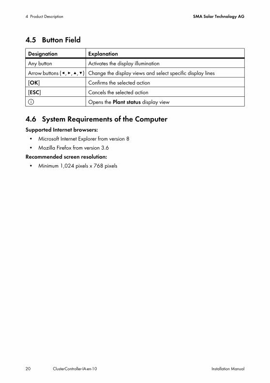
4.5 Button Field
4.6 System Requirements of the ComputerSupported Internet browsers:
• Microsoft Internet Explorer from version 8• Mozilla Firefox from version 3.6
Recommended screen resolution:• Minimum 1,024 pixels x 768 pixels
Designation ExplanationAny button Activates the display illuminationArrow buttons (◂, ▸ , ▴, ▾) Change the display views and select specific display lines[OK] Confirms the selected action[ESC] Cancels the selected actionⓘ Opens the Plant status display view
SMA Solar Technology AG 5 Assembly
Installation Manual ClusterController-IA-en-10 21
5 Assembly5.1 Selecting the Mounting LocationRequirements for the mounting location:
☐ The mounting location must be indoors.☐ The ambient conditions at the mounting location must be suitable for the operation of the
Cluster Controller (see Section 9 "Technical Data", page 77).☐ The mounting location must be protected against dust, moisture and corrosive substances.
Observe the maximum cable length:☐ Observe the respective maximum cable length of 100 m between two nodes in the Speedwire
network and in the local area network (LAN). ☐ When connecting a digital or analogue signal source (e.g. remote terminal unit, ripple control
receiver), observe the maximum cable length of 30 m from the Cluster Controller to the signal source.
☐ When connecting a temperature sensor in a four-conductor connection, observe the maximum cable length of 20 m from the Cluster Controller to the temperature sensor.
☐ When connecting a temperature sensor in a two-conductor connection, observe the maximum cable length of 2.5 m from the Cluster Controller to the temperature sensor.
Radio interference in living areas possible due to the Cluster ControllerThe Cluster Controller is a device of ITE class A (EN 55022) and can cause radio interference in living areas.
• Take suitable measures for shielding radio waves when used in the vicinity of living areas.
5 Assembly SMA Solar Technology AG
22 ClusterController-IA-en-10 Installation Manual
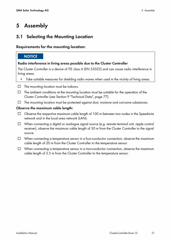
Observe minimum clearances:
Figure 7: Minimum clearances
• Maintain the minimum clearance to walls and other devices or objects.
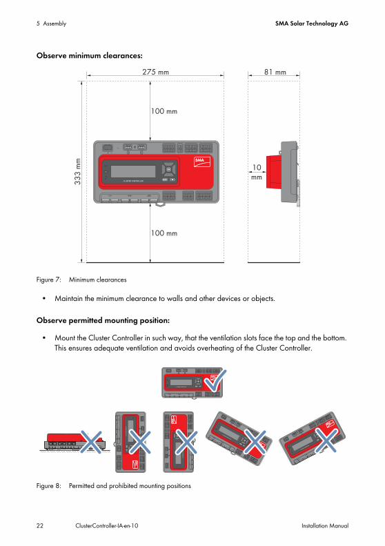
Observe permitted mounting position:
• Mount the Cluster Controller in such way, that the ventilation slots face the top and the bottom. This ensures adequate ventilation and avoids overheating of the Cluster Controller.
Figure 8: Permitted and prohibited mounting positions
SMA Solar Technology AG 5 Assembly
Installation Manual ClusterController-IA-en-10 23
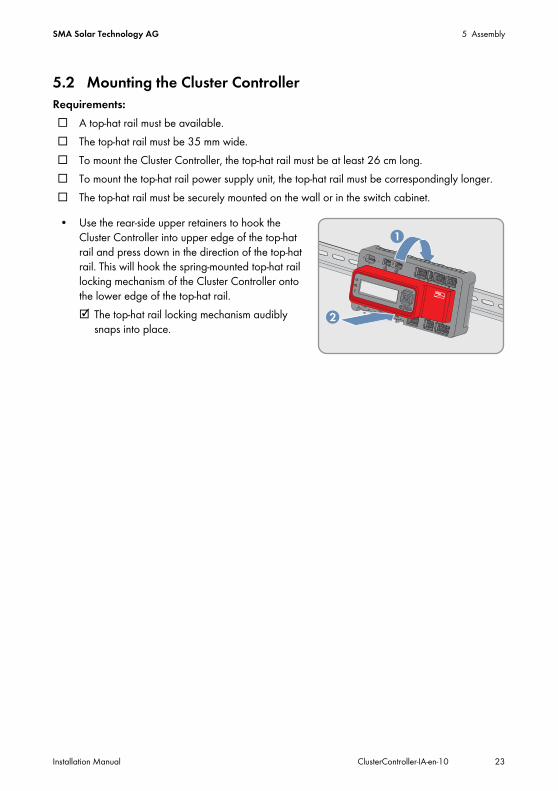
5.2 Mounting the Cluster ControllerRequirements:☐ A top-hat rail must be available.☐ The top-hat rail must be 35 mm wide.☐ To mount the Cluster Controller, the top-hat rail must be at least 26 cm long.☐ To mount the top-hat rail power supply unit, the top-hat rail must be correspondingly longer.☐ The top-hat rail must be securely mounted on the wall or in the switch cabinet.
• Use the rear-side upper retainers to hook the Cluster Controller into upper edge of the top-hat rail and press down in the direction of the top-hat rail. This will hook the spring-mounted top-hat rail locking mechanism of the Cluster Controller onto the lower edge of the top-hat rail.☑ The top-hat rail locking mechanism audibly
snaps into place.
6 Connection SMA Solar Technology AG
24 ClusterController-IA-en-10 Installation Manual
6 Connection6.1 Overview of the Connection Area
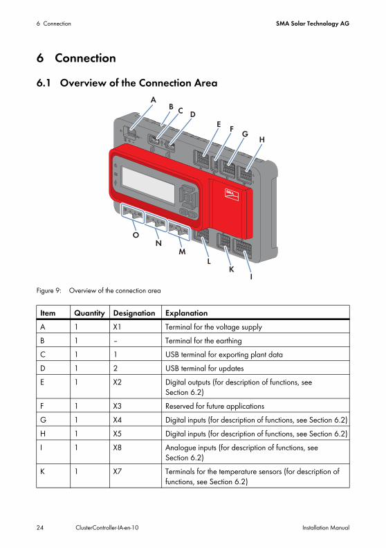
Figure 9: Overview of the connection area
Item Quantity Designation ExplanationA 1 X1 Terminal for the voltage supplyB 1 ‒ Terminal for the earthingC 1 1 USB terminal for exporting plant dataD 1 2 USB terminal for updatesE 1 X2 Digital outputs (for description of functions, see
Section 6.2)F 1 X3 Reserved for future applicationsG 1 X4 Digital inputs (for description of functions, see Section 6.2)H 1 X5 Digital inputs (for description of functions, see Section 6.2)I 1 X8 Analogue inputs (for description of functions, see
Section 6.2)K 1 X7 Terminals for the temperature sensors (for description of
functions, see Section 6.2)

SMA Solar Technology AG 6 Connection
Installation Manual ClusterController-IA-en-10 25
6.2 Functions of the Terminals and Terminal BlocksThe digital and analogue terminals of the Cluster Controller are divided into terminal blocks. A terminal block is a group of pins. Each respective pin group forms one of the digital or analogue inputs or outputs. On the enclosure, the upper row of pins is marked with A and the lower row of pins is marked with B. The pins are counted from left to right.The distribution of the terminals into terminal blocks and the functions of the terminal blocks are described in the following table.
L 1 X6 Analogue outputs (for description of functions, see Section 6.2)
M 2 X13, X14 Network terminals for local area network (LAN)N 2 X11, X12 Reserved for future applicationsO 2 X9, X10 Network terminal of the inverter (Speedwire)
Connection Terminal block Pin FunctionX1 − 1 … 3 Voltage supplyX2 Digital output 1 (DO1)
Relay AA1 … A3 Fault indication relay for the status
FaultDigital output 2 (DO2)Relay B
A4 … A6 Fault indication relay for the status Warning or Fault
Digital output 3 (DO3)Relay C
B1 … B3 Response contact for the current active power limitation under grid management
X3 − − Reserved for future applicationsX4 Digital input 1 (DI1) A1 … A3 Signal 1 of 4 for the active power
limitation under grid managementDigital input 2 (DI2) A4 … A6 Signal 2 of 4 for the active power
limitation under grid managementDigital input 3 (DI3) B1 … B3 Signal 3 of 4 for the active power
limitation under grid managementDigital input 4 (DI4) B4 … B6 Signal 4 of 4 for the active power
limitation under grid management
Item Quantity Designation Explanation
6 Connection SMA Solar Technology AG
26 ClusterController-IA-en-10 Installation Manual
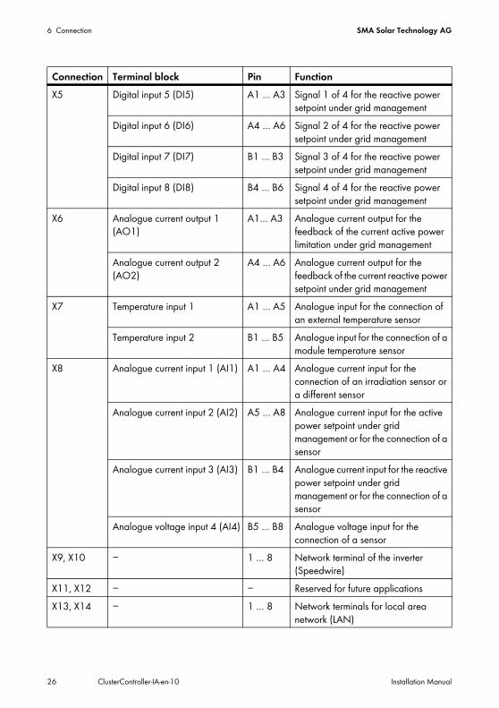
X5 Digital input 5 (DI5) A1 … A3 Signal 1 of 4 for the reactive power setpoint under grid management
Digital input 6 (DI6) A4 … A6 Signal 2 of 4 for the reactive power setpoint under grid management
Digital input 7 (DI7) B1 … B3 Signal 3 of 4 for the reactive power setpoint under grid management
Digital input 8 (DI8) B4 … B6 Signal 4 of 4 for the reactive power setpoint under grid management
X6 Analogue current output 1 (AO1)
A1… A3 Analogue current output for the feedback of the current active power limitation under grid management
Analogue current output 2 (AO2)
A4 … A6 Analogue current output for the feedback of the current reactive power setpoint under grid management
X7 Temperature input 1 A1 … A5 Analogue input for the connection of an external temperature sensor
Temperature input 2 B1 … B5 Analogue input for the connection of a module temperature sensor
X8 Analogue current input 1 (AI1) A1 … A4 Analogue current input for the connection of an irradiation sensor or a different sensor
Analogue current input 2 (AI2) A5 … A8 Analogue current input for the active power setpoint under grid management or for the connection of a sensor
Analogue current input 3 (AI3) B1 … B4 Analogue current input for the reactive power setpoint under grid management or for the connection of a sensor
Analogue voltage input 4 (AI4) B5 … B8 Analogue voltage input for the connection of a sensor
X9, X10 − 1 … 8 Network terminal of the inverter (Speedwire)
X11, X12 − − Reserved for future applicationsX13, X14 − 1 … 8 Network terminals for local area
network (LAN)
Connection Terminal block Pin Function
SMA Solar Technology AG 6 Connection
Installation Manual ClusterController-IA-en-10 27
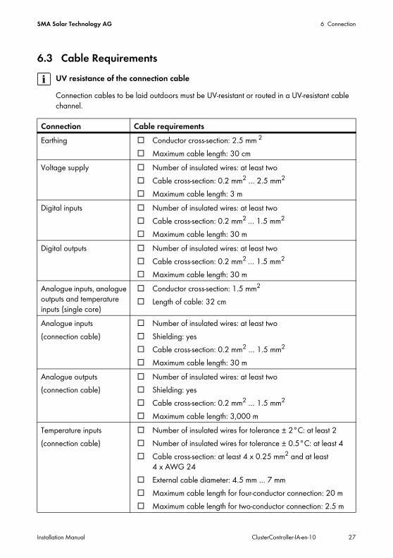
6.3 Cable RequirementsUV resistance of the connection cableConnection cables to be laid outdoors must be UV-resistant or routed in a UV-resistant cable channel.
Connection Cable requirementsEarthing ☐ Conductor cross-section: 2.5 mm 2
☐ Maximum cable length: 30 cmVoltage supply ☐ Number of insulated wires: at least two
☐ Cable cross-section: 0.2 mm2 … 2.5 mm2 ☐ Maximum cable length: 3 m
Digital inputs ☐ Number of insulated wires: at least two☐ Cable cross-section: 0.2 mm2 … 1.5 mm2 ☐ Maximum cable length: 30 m
Digital outputs ☐ Number of insulated wires: at least two☐ Cable cross-section: 0.2 mm2 … 1.5 mm2 ☐ Maximum cable length: 30 m
Analogue inputs, analogue outputs and temperature inputs (single core)
☐ Conductor cross-section: 1.5 mm2
☐ Length of cable: 32 cm
Analogue inputs(connection cable)
☐ Number of insulated wires: at least two☐ Shielding: yes☐ Cable cross-section: 0.2 mm2 … 1.5 mm2
☐ Maximum cable length: 30 mAnalogue outputs(connection cable)
☐ Number of insulated wires: at least two☐ Shielding: yes☐ Cable cross-section: 0.2 mm2 … 1.5 mm2
☐ Maximum cable length: 3,000 mTemperature inputs(connection cable)
☐ Number of insulated wires for tolerance ± 2°C: at least 2☐ Number of insulated wires for tolerance ± 0.5°C: at least 4☐ Cable cross-section: at least 4 x 0.25 mm2 and at least
4 x AWG 24☐ External cable diameter: 4.5 mm … 7 mm☐ Maximum cable length for four-conductor connection: 20 m☐ Maximum cable length for two-conductor connection: 2.5 m
6 Connection SMA Solar Technology AG
28 ClusterController-IA-en-10 Installation Manual
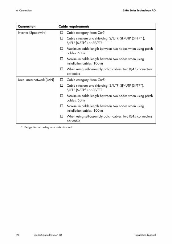
Inverter (Speedwire) ☐ Cable category: from Cat5☐ Cable structure and shielding: S/UTP, SF/UTP (S-FTP* ),
S/FTP (S-STP*) or SF/FTP☐ Maximum cable length between two nodes when using patch
cables: 50 m☐ Maximum cable length between two nodes when using
installation cables: 100 m☐ When using self-assembly patch cables: two RJ45 connectors
per cableLocal area network (LAN) ☐ Cable category: from Cat5
☐ Cable structure and shielding: S/UTP, SF/UTP (S-FTP*), S/FTP (S-STP*) or SF/FTP
☐ Maximum cable length between two nodes when using patch cables: 50 m
☐ Maximum cable length between two nodes when using installation cables: 100 m
☐ When using self-assembly patch cables: two RJ45 connectors per cable
* Designation according to an older standard
Connection Cable requirements
SMA Solar Technology AG 6 Connection
Installation Manual ClusterController-IA-en-10 29
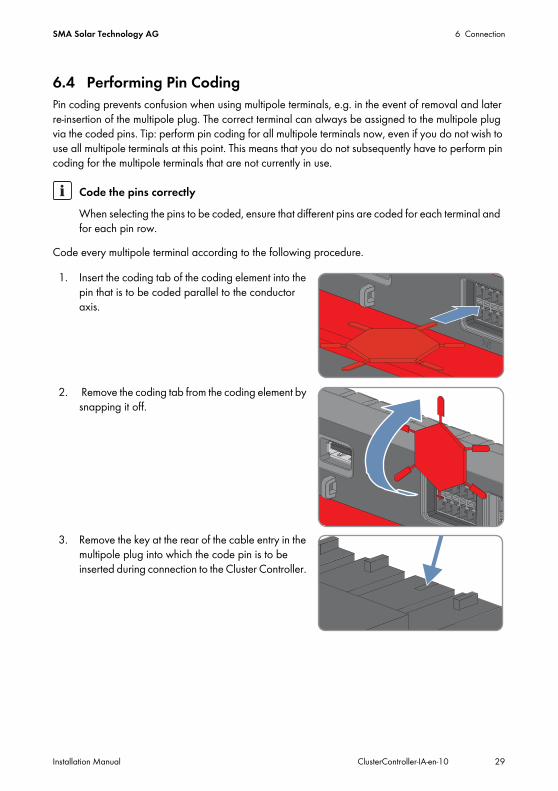
6.4 Performing Pin CodingPin coding prevents confusion when using multipole terminals, e.g. in the event of removal and later re-insertion of the multipole plug. The correct terminal can always be assigned to the multipole plug via the coded pins. Tip: perform pin coding for all multipole terminals now, even if you do not wish to use all multipole terminals at this point. This means that you do not subsequently have to perform pin coding for the multipole terminals that are not currently in use.
Code every multipole terminal according to the following procedure.
1. Insert the coding tab of the coding element into the pin that is to be coded parallel to the conductor axis.
2. Remove the coding tab from the coding element by snapping it off.
3. Remove the key at the rear of the cable entry in the multipole plug into which the code pin is to be inserted during connection to the Cluster Controller.
Code the pins correctlyWhen selecting the pins to be coded, ensure that different pins are coded for each terminal and for each pin row.
6 Connection SMA Solar Technology AG
30 ClusterController-IA-en-10 Installation Manual
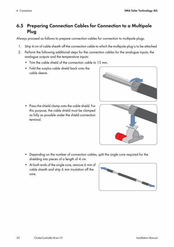
6.5 Preparing Connection Cables for Connection to a Multipole Plug
Always proceed as follows to prepare connection cables for connection to multipole plugs.
1. Strip 4 cm of cable sheath off the connection cable to which the multipole plug is to be attached.2. Perform the following additional steps for the connection cables for the analogue inputs, the
analogue outputs and the temperature inputs:• Trim the cable shield of the connection cable to 15 mm. • Fold the surplus cable shield back onto the
cable sleeve.
• Press the shield clamp onto the cable shield. For this purpose, the cable shield must be clamped as fully as possible under the shield connection terminal.
• Depending on the number of connection cables, split the single core required for the shielding into pieces of a length of 4 cm.
• At both ends of the single core, remove 6 mm of cable sheath and strip 6 mm insulation off the wire.
SMA Solar Technology AG 6 Connection
Installation Manual ClusterController-IA-en-10 31
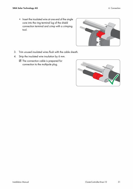
• Insert the insulated wire at one end of the single core into the ring terminal lug of the shield connection terminal and crimp with a crimping tool.
3. Trim unused insulated wires flush with the cable sheath.4. Strip the insulated wire insulation by 6 mm.
☑ The connection cable is prepared for connection to the multipole plug.
6 Connection SMA Solar Technology AG
32 ClusterController-IA-en-10 Installation Manual
6.6 Connecting the Cluster Controller to a Speedwire Network
Requirements:☐ The inverters must be equipped with Speedwire communication (depending on the feature: see
the installation manual of the inverter or the installation manual of the Speedwire/Webconnect interface).
☐ The inverters must be cabled according to one of the possible network topologies (for information on the possible network topologies as well as on the connection of the patch cable to the Speedwire/Webconnect interface, see installation manual of the inverter or installation manual of the Speedwire/Webconnect interface).
Additional required material (not included in scope of delivery):☐ Depending on the network topology: patch cables (for cable requirements, see Section 6.3)
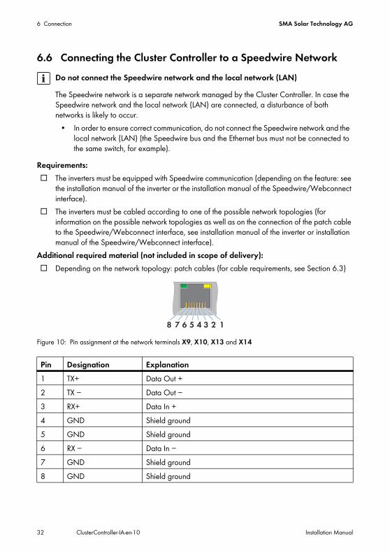
Figure 10: Pin assignment at the network terminals X9, X10, X13 and X14
Do not connect the Speedwire network and the local network (LAN)The Speedwire network is a separate network managed by the Cluster Controller. In case the Speedwire network and the local network (LAN) are connected, a disturbance of both networks is likely to occur.
• In order to ensure correct communication, do not connect the Speedwire network and the local network (LAN) (the Speedwire bus and the Ethernet bus must not be connected to the same switch, for example).
Pin Designation Explanation1 TX+ Data Out +2 TX − Data Out −3 RX+ Data In +4 GND Shield ground5 GND Shield ground6 RX − Data In −7 GND Shield ground8 GND Shield ground
SMA Solar Technology AG 6 Connection
Installation Manual ClusterController-IA-en-10 33
2. If no patch cable is connected to the inverter with integrated Speedwire communication and Webconnect function, connect the patch cable to the network socket in the inverter (see installation manual of the inverter).
3. Connect the Cluster Controller to the Speedwire network. For this purpose, observe the desired network topology:• When using a pre-configured patch cable, connect the patch cable to terminal X9 or X10.• When using a patch cable that is to be configured by the user, mount the RJ45 plug
connector on the patch cable (see the manufacturer manual) and connect the patch cable to terminal X9 or X10 of the Cluster Controller.
4. On the supplementary sheet for noting the connected devices, note the terminal to which the node is assigned.
5. Deactivate the Webconnect function of the inverters after completion of the commissioning of the Cluster Controllers (see user manual of the Cluster Controller).
1.Danger to life due to electric shock when opening the inverterLethal voltages are present in the conductive parts of the inverter.If a patch cable has not yet been connected to the retrofitted Speedwire/Webconnect interface in the inverter, perform the following steps:
• Disconnect the inverter from voltage sources on the AC and DC sides (see the inverter installation manual). Observe the waiting time to allow the capacitors to discharge.
• Open the inverter (see inverter installation manual).• Connect the patch cable to the retrofitted Speedwire/Webconnect interface (see the
installation manual of the Speedwire/Webconnect interface).• Close the inverter (see inverter installation manual).
6 Connection SMA Solar Technology AG
34 ClusterController-IA-en-10 Installation Manual
6.7 Connecting the Cluster Controller to a Local Area Network (LAN)
Additional required material (not included in scope of delivery):☐ 1 patch cable (for cable requirements, see Section 6.3)
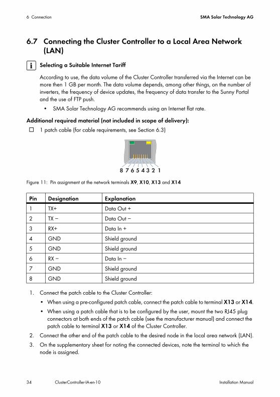
Figure 11: Pin assignment at the network terminals X9, X10, X13 and X14
1. Connect the patch cable to the Cluster Controller:• When using a pre-configured patch cable, connect the patch cable to terminal X13 or X14.• When using a patch cable that is to be configured by the user, mount the two RJ45 plug
connectors at both ends of the patch cable (see the manufacturer manual) and connect the patch cable to terminal X13 or X14 of the Cluster Controller.
2. Connect the other end of the patch cable to the desired node in the local area network (LAN).3. On the supplementary sheet for noting the connected devices, note the terminal to which the
node is assigned.
Selecting a Suitable Internet TariffAccording to use, the data volume of the Cluster Controller transferred via the Internet can be more then 1 GB per month. The data volume depends, among other things, on the number of inverters, the frequency of device updates, the frequency of data transfer to the Sunny Portal and the use of FTP push.
• SMA Solar Technology AG recommends using an Internet flat rate.
Pin Designation Explanation1 TX+ Data Out +2 TX − Data Out −3 RX+ Data In +4 GND Shield ground5 GND Shield ground6 RX − Data In −7 GND Shield ground8 GND Shield ground
SMA Solar Technology AG 6 Connection
Installation Manual ClusterController-IA-en-10 35
6.8 Setting Up a Modbus Data ConnectionAdditional required accessories (not included in scope of delivery):☐ Up to two Modbus clients
Requirements:☐ The Cluster Controller and the Modbus client must be located on the same local area network
(LAN) (for information on connecting the Cluster Controller to the local area network (LAN), see Section 6.7).
☐ The commissioning of the Cluster Controller must be completed.Perform the setup of the Modbus data connection via the user interface of the Cluster Controller (see the Cluster Controller user manual) and the Modbus client (see the manufacturer manual). You can find further information on possible Modbus settings on the Cluster Controller in the technical description "SMA CLUSTER CONTROLLER Modbus® Interface".
6.9 Connecting USB Data Carriers to the Cluster ControllerIn order to save plant data or perform an update, you can connect up to two USB data carriers to the Cluster Controller (for information on updates, see the Cluster Controller user manual).
Additional required accessories (not included in scope of delivery):☐ Up to two USB data carriers, e.g. two USB sticks (see Section 10 "Accessories", page 81)
If you use a USB data carrier other than that provided by SMA Solar Technology AG as an accessory, the USB data carrier must correspond to the requirements stated below.Requirements for USB data carriers:☐ Supported file systems: FAT 16 or FAT 32
Period of ArchivingDepending on the available storage capacity of the USB data carrier and your plant's configuration, the following, approximate periods of archiving for the plant data are possible:
Not possible to use USB Ethernet hubsThe Cluster Controller does not support any USB Ethernet hubs. You must connect the USB data carrier directly to the desired USB terminal on the Cluster Controller.
Number of connected inverters
Approximate period of archiving4 GB memory capacity 8 GB memory capacity
5 10 years 20 years10 5 years 10 years25 2 years 4 years50 1 year 2 years75 9 months 18 months
6 Connection SMA Solar Technology AG
36 ClusterController-IA-en-10 Installation Manual
1. To protect the USB data carrier against loss, attach the USB data carrier to the eyelets located on the underside of the USB plug e.g. using a loop attached to the USB data carrier.
2. Connect the USB data carrier to the desired USB terminal:• To export plant data, connect the USB data carrier to the USB terminal 1.• To transmit update files to the Cluster Controller, connect the USB data carrier to USB
terminal 2.3. If the USB data carrier is permanently inserted into the Cluster Controller, the USB terminal to
which the USB data carrier is assigned must be noted down on the supplementary sheet for noting the connected devices.
4. If the USB data carrier is to be removed from the Cluster Controller again, wait until the data carrier status LED ( ) is not flashing anymore..
SMA Solar Technology AG 6 Connection
Installation Manual ClusterController-IA-en-10 37
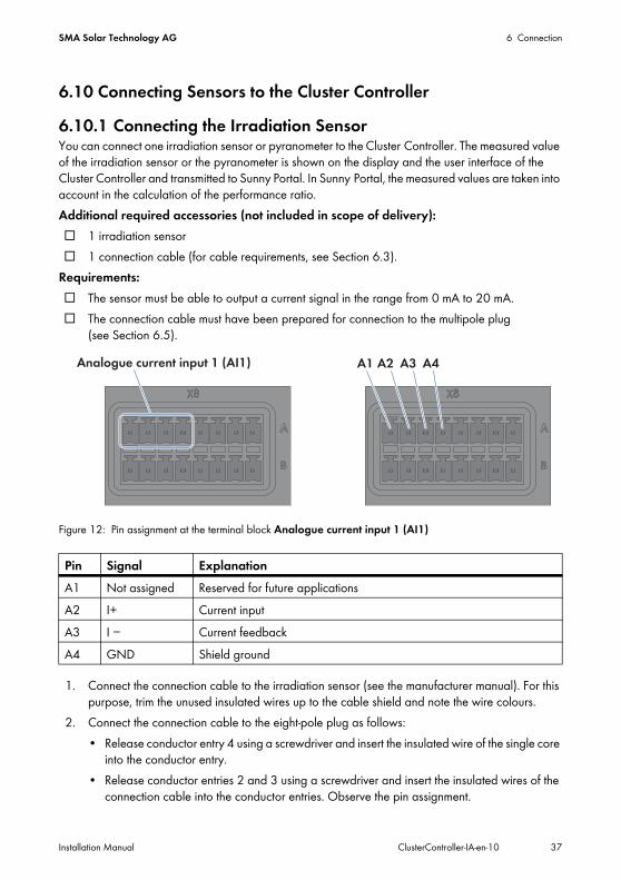
6.10 Connecting Sensors to the Cluster Controller6.10.1 Connecting the Irradiation SensorYou can connect one irradiation sensor or pyranometer to the Cluster Controller. The measured value of the irradiation sensor or the pyranometer is shown on the display and the user interface of the Cluster Controller and transmitted to Sunny Portal. In Sunny Portal, the measured values are taken into account in the calculation of the performance ratio.Additional required accessories (not included in scope of delivery):☐ 1 irradiation sensor☐ 1 connection cable (for cable requirements, see Section 6.3).
Requirements:☐ The sensor must be able to output a current signal in the range from 0 mA to 20 mA.☐ The connection cable must have been prepared for connection to the multipole plug
(see Section 6.5).
Figure 12: Pin assignment at the terminal block Analogue current input 1 (AI1)
1. Connect the connection cable to the irradiation sensor (see the manufacturer manual). For this purpose, trim the unused insulated wires up to the cable shield and note the wire colours.
2. Connect the connection cable to the eight-pole plug as follows:• Release conductor entry 4 using a screwdriver and insert the insulated wire of the single core
into the conductor entry.• Release conductor entries 2 and 3 using a screwdriver and insert the insulated wires of the
connection cable into the conductor entries. Observe the pin assignment.
Pin Signal ExplanationA1 Not assigned Reserved for future applicationsA2 I+ Current inputA3 I − Current feedbackA4 GND Shield ground
6 Connection SMA Solar Technology AG
38 ClusterController-IA-en-10 Installation Manual
3. Insert the eight-pole plug at terminal X8 into pin row A. 4. On the connection cable, mark the terminal and pin row to which the connection cable is
assigned. For this purpose, use the cable ties with the caption field.5. On the supplementary sheet for noting the connected devices, note the terminal to which the
sensor is assigned.6. Adjust the characteristic curve of the irradiation sensor or pyranometer via the user interface of
the Cluster Controller (see the Cluster Controller user manual). The measured irradiation values can therefore be shown on the display and the user interface of the Cluster Controller.
SMA Solar Technology AG 6 Connection
Installation Manual ClusterController-IA-en-10 39
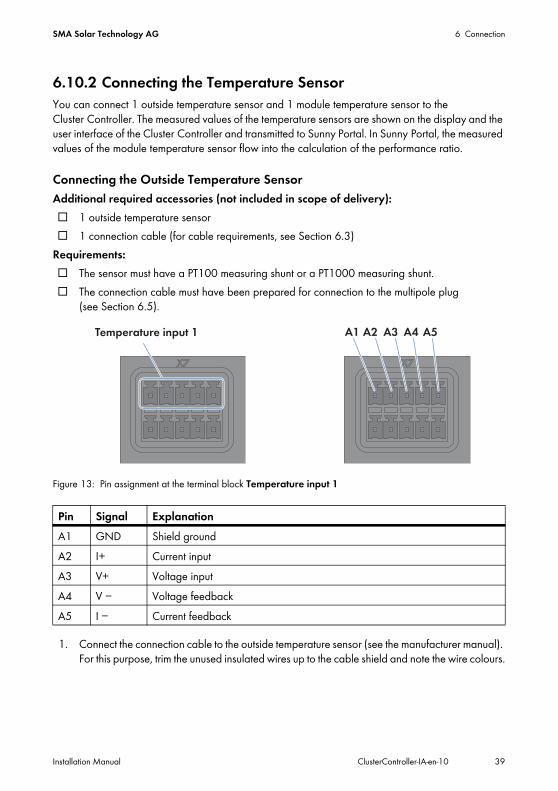
6.10.2 Connecting the Temperature SensorYou can connect 1 outside temperature sensor and 1 module temperature sensor to the Cluster Controller. The measured values of the temperature sensors are shown on the display and the user interface of the Cluster Controller and transmitted to Sunny Portal. In Sunny Portal, the measured values of the module temperature sensor flow into the calculation of the performance ratio.
Connecting the Outside Temperature SensorAdditional required accessories (not included in scope of delivery):☐ 1 outside temperature sensor☐ 1 connection cable (for cable requirements, see Section 6.3)
Requirements:☐ The sensor must have a PT100 measuring shunt or a PT1000 measuring shunt.☐ The connection cable must have been prepared for connection to the multipole plug
(see Section 6.5).
Figure 13: Pin assignment at the terminal block Temperature input 1
1. Connect the connection cable to the outside temperature sensor (see the manufacturer manual). For this purpose, trim the unused insulated wires up to the cable shield and note the wire colours.
Pin Signal ExplanationA1 GND Shield groundA2 I+ Current inputA3 V+ Voltage inputA4 V − Voltage feedbackA5 I − Current feedback

6 Connection SMA Solar Technology AG
40 ClusterController-IA-en-10 Installation Manual
2. Connect the connection cable to the five-pole plug as follows:• Release conductor entry 1 using a screwdriver and insert the insulated wire of the single core
into the conductor entry.• For two-conductor connection, release conductor entries 3 and 4 using a screwdriver and
insert the insulated wires of the connection cable into the conductor entries. Observe the pin assignment.
• For four-conductor connection, release conductor entries 2, 3, 4 and 5 using a screwdriver and insert the insulated wires of the connection cable into the conductor entries. Observe the pin assignment.
3. Insert the five-pole plug at terminal X7 into pin row A. 4. On the connection cable, mark the terminal and pin row to which the connection cable is
assigned. For this purpose, use the cable ties with the caption field.5. On the supplementary sheet for noting the connected devices, note the terminal to which the
sensor is assigned.
Connecting the Module Temperature SensorAdditional required accessories (not included in scope of delivery):☐ 1 module temperature sensor☐ 1 connection cable (for cable requirements, see Section 6.3)
Requirements:☐ The sensor must have a PT100 measuring shunt or a PT1000 measuring shunt.☐ The connection cable must have been prepared for connection to the multipole plug
(see Section 6.5).
Figure 14: Pin assignment at the terminal block Temperature input 2
Pin Signal ExplanationB1 GND Shield groundB2 I+ Current inputB3 V+ Voltage input
SMA Solar Technology AG 6 Connection
Installation Manual ClusterController-IA-en-10 41
1. Connect the connection cable to the module temperature sensor (see the manufacturer manual). For this purpose, trim the unused insulated wires up to the cable shield and note the wire colours.
2. Connect the connection cable to the five-pole plug as follows:• Release conductor entry 1 using a screwdriver and insert the insulated wire of the single core
into the conductor entry.• For two-conductor connection, release conductor entries 3 and 4 using a screwdriver and
insert the insulated wires of the connection cable into the conductor entries. Observe the pin assignment.
• For four-conductor connection, release conductor entries 2, 3, 4 and 5 using a screwdriver and insert the insulated wires of the connection cable into the conductor entries. Observe the pin assignment.
3. Insert the five-pole plug at terminal X7 into pin row B. 4. On the connection cable, mark the terminal and pin row to which the connection cable is
assigned. For this purpose, use the cable ties with the caption field.5. On the supplementary sheet for noting the connected devices, note the terminal to which the
sensor is assigned.
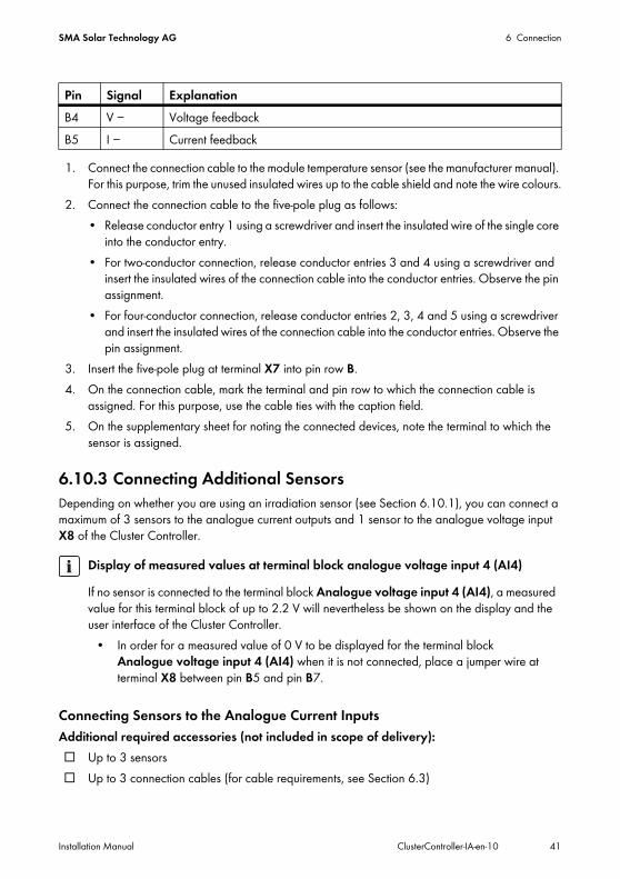
6.10.3 Connecting Additional SensorsDepending on whether you are using an irradiation sensor (see Section 6.10.1), you can connect a maximum of 3 sensors to the analogue current outputs and 1 sensor to the analogue voltage input X8 of the Cluster Controller.
Connecting Sensors to the Analogue Current InputsAdditional required accessories (not included in scope of delivery):☐ Up to 3 sensors☐ Up to 3 connection cables (for cable requirements, see Section 6.3)
B4 V − Voltage feedbackB5 I − Current feedback
Display of measured values at terminal block analogue voltage input 4 (AI4)If no sensor is connected to the terminal block Analogue voltage input 4 (AI4), a measured value for this terminal block of up to 2.2 V will nevertheless be shown on the display and the user interface of the Cluster Controller.
• In order for a measured value of 0 V to be displayed for the terminal block Analogue voltage input 4 (AI4) when it is not connected, place a jumper wire at terminal X8 between pin B5 and pin B7.
Pin Signal Explanation
6 Connection SMA Solar Technology AG
42 ClusterController-IA-en-10 Installation Manual
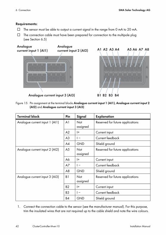
Requirements:☐ The sensor must be able to output a current signal in the range from 0 mA to 20 mA.☐ The connection cable must have been prepared for connection to the multipole plug
(see Section 6.5)
Figure 15: Pin assignment at the terminal blocks Analogue current input 1 (AI1), Analogue current input 2 (AI2) and Analogue current input 3 (AI3)
1. Connect the connection cable to the sensor (see the manufacturer manual). For this purpose, trim the insulated wires that are not required up to the cable shield and note the wire colours.
Terminal block Pin Signal ExplanationAnalogue current input 1 (AI1) A1 Not
assignedReserved for future applications
A2 I+ Current inputA3 I − Current feedbackA4 GND Shield ground
Analogue current input 2 (AI2) A5 Not assigned
Reserved for future applications
A6 I+ Current inputA7 I − Current feedbackA8 GND Shield ground
Analogue current input 3 (AI3) B1 Not assigned
Reserved for future applications
B2 I+ Current inputB3 I − Current feedbackB4 GND Shield ground
SMA Solar Technology AG 6 Connection
Installation Manual ClusterController-IA-en-10 43
2. For connecting to the terminal block Analogue current input 1 (AI1), perform the following steps: • Release conductor entry 4 using a screwdriver and insert the insulated wire of the single core
into the conductor entry.• Release conductor entries 2 and 3 using a screwdriver and insert the insulated wires of the
connection cable into the conductor entries. Observe the pin assignment.• Insert the eight-pole plug at terminal X8 into pin row A.
3. For connecting to the terminal block Analogue current input 2 (AI2), perform the following steps: • Release conductor entry 8 using a screwdriver and insert the insulated wire of the single core
into the conductor entry.• Release conductor entries 6 and 7 using a screwdriver and insert the insulated wires of the
connection cable into the conductor entries. Observe the pin assignment.• Insert the eight-pole plug at terminal X8 into pin row A.
4. For connecting to the terminal block Analogue current input 3 (AI3), perform the following steps: • Release conductor entry 4 using a screwdriver and insert the insulated wire of the single core
into the conductor entry.• Release conductor entries 2 and 3 using a screwdriver and insert the insulated wires of the
connection cable into the conductor entries. Observe the pin assignment.• Insert the eight-pole plug at terminal X8 into pin row B.
5. On the connection cable, mark the terminal and pin row to which the connection cable is assigned. For this purpose, use the cable ties with the caption field.
6. On the supplementary sheet for noting the connected devices, note the terminal to which the sensor is assigned.
Connecting the Sensor to the Analogue Voltage InputAdditional required accessories (not included in scope of delivery):☐ 1 sensor☐ 1 connection cable (for cable requirements, see Section 6.3)
Requirements:☐ The sensor must be able to output a voltage signal in the range from − 10 V to +10 V.☐ The connection cable must have been prepared for connection to the multipole plug
(see Section 6.5)

6 Connection SMA Solar Technology AG
44 ClusterController-IA-en-10 Installation Manual
Figure 16: Pin assignment at the terminal block Analogue voltage input 4 (AI4)
1. Connect the connection cable to the sensor (see the manufacturer manual). For this purpose, trim the insulated wires that are not required up to the cable shield and note the wire colours.
2. Connect the connection cable to the eight-pole plug as follows:• Release conductor entry 8 using a screwdriver and insert the insulated wire of the single core
into the conductor entry.• Release conductor entries 5 and 7 using a screwdriver and insert the insulated wires of the
connection cable into the conductor entries. Observe the pin assignment.3. Insert the eight-pole plug at terminal X8 into pin row B.4. On the connection cable, mark the terminal and pin row to which the connection cable is
assigned. For this purpose, use the cable ties with the caption field.5. On the supplementary sheet for noting the connected devices, note the terminal to which the
sensor is assigned.
Pin Signal ExplanationB5 V+ Voltage inputB6 Not
assignedReserved for future applications
B7 V − Voltage feedbackB8 GND Shield ground
SMA Solar Technology AG 6 Connection
Installation Manual ClusterController-IA-en-10 45
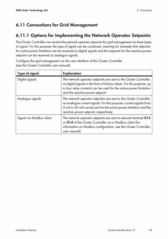
6.11 Connections for Grid Management
6.11.1 Options for Implementing the Network Operator SetpointsThe Cluster Controller can receive the network operator setpoints for grid management via three types of signal. For this purpose, the type of signal can be combined, meaning for example that setpoints for active power limitation can be received as digital signals and the setpoints for the reactive power setpoint can be received as analogue signals.Configure the grid management via the user interface of the Cluster Controller (see the Cluster Controller user manual).
Type of signal ExplanationDigital signals The network operator setpoints are sent to the Cluster Controller
as digital signals in the form of binary values. For this purpose, up to four relay contacts can be used for the active power limitation and the reactive power setpoint.
Analogue signals The network operator setpoints are sent to the Cluster Controller as analogue current signals. For this purpose, current signals from 0 mA to 20 mA can be sent for the active power limitation and the reactive power setpoint, respectively.
Signal via Modbus client The network operator setpoints are sent to network terminal X13 or X14 of the Cluster Controller via a Modbus client (for information on Modbus configuration, see the Cluster Controller user manual).
6 Connection SMA Solar Technology AG
46 ClusterController-IA-en-10 Installation Manual
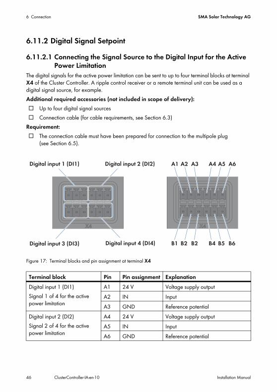
6.11.2 Digital Signal Setpoint6.11.2.1 Connecting the Signal Source to the Digital Input for the Active
Power LimitationThe digital signals for the active power limitation can be sent to up to four terminal blocks at terminal X4 of the Cluster Controller. A ripple control receiver or a remote terminal unit can be used as a digital signal source, for example.Additional required accessories (not included in scope of delivery):☐ Up to four digital signal sources☐ Connection cable (for cable requirements, see Section 6.3)
Requirement:☐ The connection cable must have been prepared for connection to the multipole plug
(see Section 6.5).
Figure 17: Terminal blocks and pin assignment at terminal X4
Terminal block Pin Pin assignment ExplanationDigital input 1 (DI1)Signal 1 of 4 for the active power limitation
A1 24 V Voltage supply outputA2 IN InputA3 GND Reference potential
Digital input 2 (DI2)Signal 2 of 4 for the active power limitation
A4 24 V Voltage supply outputA5 IN InputA6 GND Reference potential
SMA Solar Technology AG 6 Connection
Installation Manual ClusterController-IA-en-10 47
1. Connect the connection cable to the digital signal source (see the manufacturer manual). For this purpose, trim the unused insulated wires up to the cable shield and note the wire colours.
2. Connect the connection cable to the six-pole plug as follows:• Depending on the digital signal source and the pin assignment at terminal X4, identify the
conductor entries that will be required for connecting the connection cable. • Release the required conductor entries using a screwdriver and insert the insulated wires into
the conductor entries. Observe the pin assignment. 3. Connect the six-pole plug to terminal X4. For this purpose, observe the pin coding.4. On the connection cable, mark the terminal and pin row to which the connection cable is
assigned. For this purpose, use the cable ties with the caption field.5. On the supplementary sheet for noting the connected devices, note the terminal to which the
digital signal source is assigned.
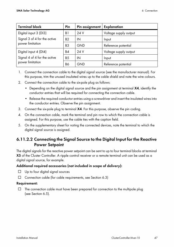
6.11.2.2 Connecting the Signal Source to the Digital Input for the Reactive Power Setpoint
The digital signals for the reactive power setpoint can be sent to up to four terminal blocks at terminal X5 of the Cluster Controller. A ripple control receiver or a remote terminal unit can be used as a digital signal source, for example.Additional required accessories (not included in scope of delivery):☐ Up to four digital signal sources☐ Connection cable (for cable requirements, see Section 6.3)
Requirement:☐ The connection cable must have been prepared for connection to the multipole plug
(see Section 6.5).
Digital input 3 (DI3)Signal 3 of 4 for the active power limitation
B1 24 V Voltage supply outputB2 IN InputB3 GND Reference potential
Digital input 4 (DI4)Signal 4 of 4 for the active power limitation
B4 24 V Voltage supply outputB5 IN InputB6 GND Reference potential
Terminal block Pin Pin assignment Explanation
6 Connection SMA Solar Technology AG
48 ClusterController-IA-en-10 Installation Manual
Figure 18: Terminal blocks and pin assignment at terminal X5
1. Connect the connection cable to the digital signal source (see the manufacturer manual). For this purpose, trim the unused insulated wires up to the cable shield and note the wire colours.
2. Connect the connection cable to the six-pole plug as follows:• Depending on the digital signal source and the pin assignment at terminal X5, identify the
conductor entries that will be required for connecting the connection cable. • Release the required conductor entries using a screwdriver and insert the insulated wires into
the conductor entries. Observe the pin assignment.3. Connect the six-pole plug to terminal X5. For this purpose, observe the pin coding.
Terminal block Pin Pin assignment ExplanationDigital input 5 (DI5)Signal 1 of 4 for the reactive power setpoint
A1 24 V Voltage supply outputA2 IN InputA3 GND Reference potential
Digital input 6 (DI6)Signal 2 of 4 for the reactive power setpoint
A4 24 V Voltage supply outputA5 IN InputA6 GND Reference potential
Digital input 7 (DI7)Signal 3 of 4 for the reactive power setpoint
B1 24 V Voltage supply outputB2 IN InputB3 GND Reference potential
Digital input 8 (DI8)Signal 4 of 4 for the reactive power setpoint
B4 24 V Voltage supply outputB5 IN InputB6 GND Reference potential
SMA Solar Technology AG 6 Connection
Installation Manual ClusterController-IA-en-10 49
4. On the connection cable, mark the terminal and pin row to which the connection cable is assigned. For this purpose, use the cable ties with the caption field.
5. On the supplementary sheet for noting the connected devices, note the terminal to which the digital signal source is assigned.
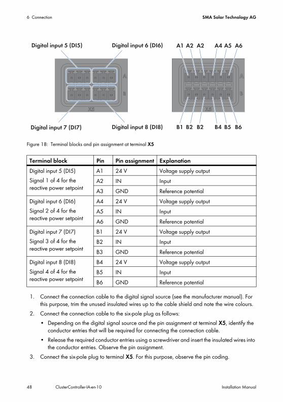
6.11.3 Analogue Signal Setpoint6.11.3.1 Connecting the Signal Source to the Analogue Input for the
Active Power LimitationThe analogue signals for the active power limitation are sent to the terminal block Analogue current input 2 (AI2) at terminal X8 of the Cluster Controller. A remote terminal unit can be used as an analogue signal source, for example.Additional required accessories (not included in scope of delivery):☐ 1 analogue signal source☐ Connection cable (for cable requirements, see Section 6.3)
Requirements:☐ The analogue signal source must be able to output a current signal in the range from
0 mA to 20 mA.☐ The connection cable must have been prepared for connection to the multipole plug
(see Section 6.5).
Figure 19: Pin assignment at the terminal block Analogue current input 2 (AI2)
Pin Signal ExplanationA5 Not
assignedReserved for future applications
A6 I+ Current inputA7 I − Current feedbackA8 GND Shield ground
6 Connection SMA Solar Technology AG
50 ClusterController-IA-en-10 Installation Manual
1. Connect the connection cable to the analogue signal source (see the manufacturer manual). For this purpose, trim the unused insulated wires up to the cable shield and note the wire colours.
2. Connect the connection cable to the eight-pole plug as follows:• Release conductor entry 8 using a screwdriver and insert the insulated wire of the single core
into the conductor entry.• Release conductor entries 6 and 7 using a screwdriver and insert the insulated wires of the
connection cable into the conductor entries. Observe the pin assignment.3. Insert the eight-pole plug at terminal X8 into pin row A. 4. On the connection cable, mark the terminal and pin row to which the connection cable is
assigned. For this purpose, use the cable ties with the caption field.5. On the supplementary sheet for noting the connected devices, note the terminal to which the
analogue signal source is assigned.
SMA Solar Technology AG 6 Connection
Installation Manual ClusterController-IA-en-10 51
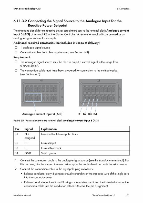
6.11.3.2 Connecting the Signal Source to the Analogue Input for the Reactive Power Setpoint
The analogue signals for the reactive power setpoint are sent to the terminal block Analogue current input 3 (AI3) at terminal X8 of the Cluster Controller. A remote terminal unit can be used as an analogue signal source, for example.Additional required accessories (not included in scope of delivery):☐ 1 analogue signal source☐ Connection cable (for cable requirements, see Section 6.3)
Requirement:☐ The analogue signal source must be able to output a current signal in the range from
0 mA to 20 mA.☐ The connection cable must have been prepared for connection to the multipole plug
(see Section 6.5).
Figure 20: Pin assignment at the terminal block Analogue current input 3 (AI3)
1. Connect the connection cable to the analogue signal source (see the manufacturer manual). For this purpose, trim the unused insulated wires up to the cable shield and note the wire colours
2. Connect the connection cable to the eight-pole plug as follows:• Release conductor entry 4 using a screwdriver and insert the insulated wire of the single core
into the conductor entry.• Release conductor entries 2 and 3 using a screwdriver and insert the insulated wires of the
connection cable into the conductor entries. Observe the pin assignment.
Pin Signal ExplanationB1 Not
assignedReserved for future applications
B2 I+ Current inputB3 I − Current feedbackB4 GND Shield ground
6 Connection SMA Solar Technology AG
52 ClusterController-IA-en-10 Installation Manual
3. Insert the eight-pole plug at terminal X8 into pin row B.4. On the connection cable, mark the terminal and pin row to which the connection cable is
assigned. For this purpose, use the cable ties with the caption field.5. On the supplementary sheet for noting the connected devices, note the terminal to which the
analogue signal source is assigned.
6.11.4 Setpoint via Modbus ClientRequirements:☐ The Cluster Controller and the Modbus client must be located on the same local area network
(LAN) (see Section 6.8).☐ The commissioning of the Cluster Controller must be completed.
In order to receive the network operator setpoints via a Modbus client, you must perform the Modbus configuration via the user interface of the Cluster Controller after completing the commissioning (see the Cluster Controller user manual).
6.11.5 Connecting the Remote Terminal for Feedback of Network Operator Setpoints
If the Cluster Controller sends the network operator setpoints for grid management to the inverters in the plant, you have the option of providing related feedback to the network operator. For this purpose, the Cluster Controller prepares one digital output and two analogue current outputs as response contacts to which you can connect corresponding remote terminals, e.g. a remote terminal unit.
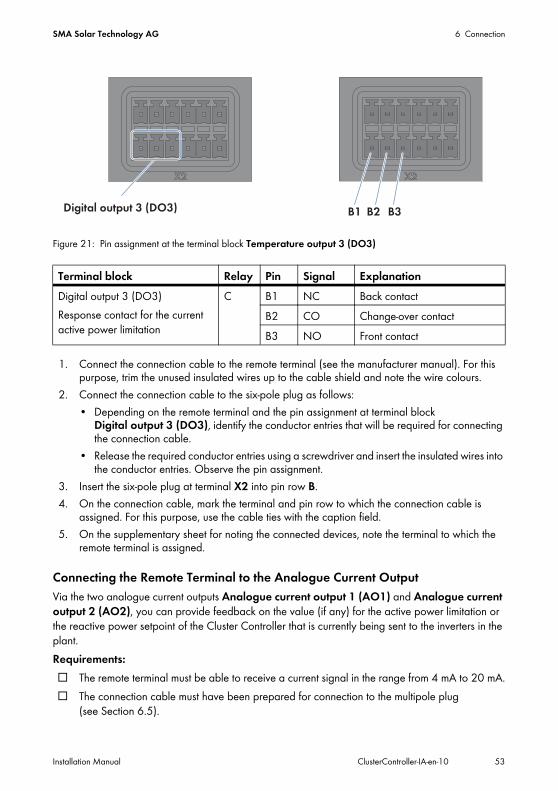
Connecting the Remote Terminal to the Digital OutputVia the terminal block Digital output 3 (DO3), you can provide feedback on whether the Cluster Controller has sent a network operator setpoint for the active power limitation to the inverters in the plant.
Requirement:☐ The connection cable must have been prepared for connection to the multipole plug
(see Section 6.5).
Observe the maximum load capacity of the relay contactsThe relay contacts may be loaded with a maximum switching capacity of 30 watts and a maximum voltage of 48 V DC (see Section 9 "Technical Data", page 77).
SMA Solar Technology AG 6 Connection
Installation Manual ClusterController-IA-en-10 53
Figure 21: Pin assignment at the terminal block Temperature output 3 (DO3)
1. Connect the connection cable to the remote terminal (see the manufacturer manual). For this purpose, trim the unused insulated wires up to the cable shield and note the wire colours.
2. Connect the connection cable to the six-pole plug as follows:• Depending on the remote terminal and the pin assignment at terminal block
Digital output 3 (DO3), identify the conductor entries that will be required for connecting the connection cable.
• Release the required conductor entries using a screwdriver and insert the insulated wires into the conductor entries. Observe the pin assignment.
3. Insert the six-pole plug at terminal X2 into pin row B.4. On the connection cable, mark the terminal and pin row to which the connection cable is
assigned. For this purpose, use the cable ties with the caption field.5. On the supplementary sheet for noting the connected devices, note the terminal to which the
remote terminal is assigned.
Connecting the Remote Terminal to the Analogue Current OutputVia the two analogue current outputs Analogue current output 1 (AO1) and Analogue current output 2 (AO2), you can provide feedback on the value (if any) for the active power limitation or the reactive power setpoint of the Cluster Controller that is currently being sent to the inverters in the plant.Requirements:☐ The remote terminal must be able to receive a current signal in the range from 4 mA to 20 mA.☐ The connection cable must have been prepared for connection to the multipole plug
(see Section 6.5).
Terminal block Relay Pin Signal ExplanationDigital output 3 (DO3)Response contact for the current active power limitation
C B1 NC Back contactB2 CO Change-over contactB3 NO Front contact
6 Connection SMA Solar Technology AG
54 ClusterController-IA-en-10 Installation Manual
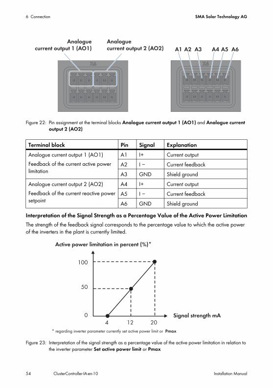
Figure 22: Pin assignment at the terminal blocks Analogue current output 1 (AO1) and Analogue current output 2 (AO2)
Interpretation of the Signal Strength as a Percentage Value of the Active Power LimitationThe strength of the feedback signal corresponds to the percentage value to which the active power of the inverters in the plant is currently limited.
Figure 23: Interpretation of the signal strength as a percentage value of the active power limitation in relation to the inverter parameter Set active power limit or Pmax
Terminal block Pin Signal ExplanationAnalogue current output 1 (AO1)Feedback of the current active power limitation
A1 I+ Current outputA2 I − Current feedbackA3 GND Shield ground
Analogue current output 2 (AO2)Feedback of the current reactive power setpoint
A4 I+ Current outputA5 I − Current feedbackA6 GND Shield ground
SMA Solar Technology AG 6 Connection
Installation Manual ClusterController-IA-en-10 55
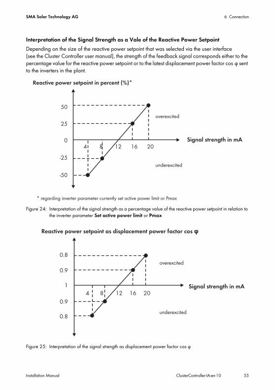
Interpretation of the Signal Strength as a Vale of the Reactive Power SetpointDepending on the size of the reactive power setpoint that was selected via the user interface (see the Cluster Controller user manual), the strength of the feedback signal corresponds either to the percentage value for the reactive power setpoint or to the latest displacement power factor cos φ sent to the inverters in the plant.
Figure 24: Interpretation of the signal strength as a percentage value of the reactive power setpoint in relation to the inverter parameter Set active power limit or Pmax
Figure 25: Interpretation of the signal strength as displacement power factor cos φ
6 Connection SMA Solar Technology AG
56 ClusterController-IA-en-10 Installation Manual
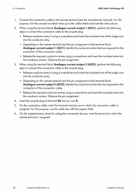
1. Connect the connection cable to the remote terminal (see the manufacturer manual). For this purpose, trim the unused insulated wires up to the cable shield and note the wire colours.
2. When using the terminal block Analogue current output 1 (AO1), perform the following steps to connect the connection cable to the six-pole plug:• Release conductor entry 3 using a screwdriver and insert the insulated wire of the single core
into the conductor entry.• Depending on the remote terminal and the pin assignment at the terminal block
Analogue current output 1 (AO1), identify the conductor entries that are required for the connection of the connection cable.
• Release the required conductor entries using a screwdriver and insert the insulated wires into the conductor entries. Observe the pin assignment.
3. When using the terminal block Analogue current output 2 (AO2), perform the following steps to connect the connection cable to the six-pole plug:• Release conductor entry 6 using a screwdriver and insert the insulated wire of the single core
into the conductor entry.• Depending on the remote terminal and the pin assignment at the terminal block
Analogue current output 2 (AO2), identify the conductor entries that are required for the connection of the connection cable.
• Release the required conductor entries using a screwdriver and insert the insulated wires into the conductor entries. Observe the pin assignment.
4. Insert the six-pole plug at terminal X6 into pin row A.5. On the connection cable, mark the terminal and pin row to which the connection cable is
assigned. For this purpose, use the cable ties with the caption field.6. On the supplementary sheet for noting the connected devices, note the terminal to which the
remote terminal is assigned.

SMA Solar Technology AG 6 Connection
Installation Manual ClusterController-IA-en-10 57
6.12 Using Fault Indication RelaysYou can connect up to three remote terminals (e.g. optical or acoustic signal generators) to the three potential-free relay contacts of the Cluster Controller. The relay contacts are implemented as two fault indication relays and one response contact. Via the fault indication relay Digital output 1 (DO1), you can signal the plant status Fault. Via the fault indication relay Digital output 2 (DO2), you can signal the plant status Fault or Warning.
Requirement:☐ The connection cable must have been prepared for connection to the multipole plug (see
Section 6.5).
Figure 26: Pin assignment at the terminal blocks Digital output 1 (DO1) and Digital output 2 (DO2)
1. Connect the connection cable to the remote terminal (see the manufacturer manual). For this purpose, trim the unused insulated wires up to the cable shield and note the wire colours.
Observe the maximum load capacity of the relay contactsThe relay contacts may be loaded with a maximum switching capacity of 30 watts and a maximum voltage of 48 V DC (see Section 9 "Technical Data", page 77).
Terminal block Relay Pin Signal ExplanationDigital output 1 (DO1)Fault indication relay for the plant status Fault
A A1 NC Back contactA2 CO Change-over contactA3 NO Front contact
Digital output 2 (DO2)Fault indication relay for the plant status Fault or Warning
B A4 NC Back contactA5 CO Change-over contactA6 NO Front contact
6 Connection SMA Solar Technology AG
58 ClusterController-IA-en-10 Installation Manual
2. Connect the connection cable to the six-pole plug as follows:• Depending on the remote terminal and the pin assignment at the terminal blocks
Digital output 1 (DO1) and Digital output 2 (DO2), identify the conductor entries that are required for the connection of the connection cable.
• Release the required conductor entries using a screwdriver and insert the insulated wires into the conductor entries. Observe the pin assignment.
3. Insert the six-pole plug at terminal X2 into pin row A.4. On the connection cable, mark the terminal and pin row to which the connection cable is
assigned. For this purpose, use the cable ties with the caption field.5. On the supplementary sheet for noting the connected devices, note the terminal to which the
remote terminal is assigned.
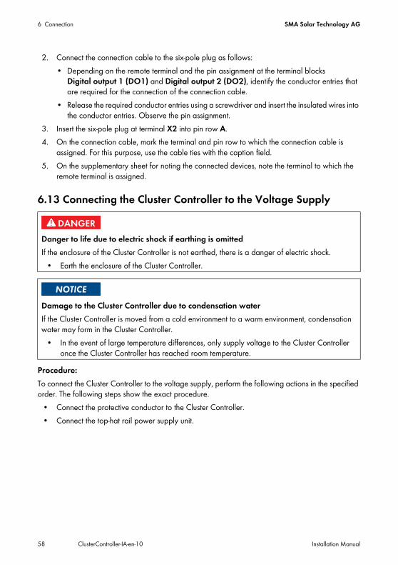
6.13 Connecting the Cluster Controller to the Voltage Supply
Procedure:To connect the Cluster Controller to the voltage supply, perform the following actions in the specified order. The following steps show the exact procedure.
• Connect the protective conductor to the Cluster Controller.• Connect the top-hat rail power supply unit.
Danger to life due to electric shock if earthing is omittedIf the enclosure of the Cluster Controller is not earthed, there is a danger of electric shock.
• Earth the enclosure of the Cluster Controller.
Damage to the Cluster Controller due to condensation waterIf the Cluster Controller is moved from a cold environment to a warm environment, condensation water may form in the Cluster Controller.
• In the event of large temperature differences, only supply voltage to the Cluster Controller once the Cluster Controller has reached room temperature.
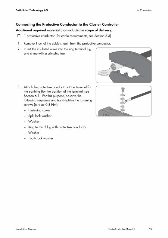
SMA Solar Technology AG 6 Connection
Installation Manual ClusterController-IA-en-10 59
Connecting the Protective Conductor to the Cluster ControllerAdditional required material (not included in scope of delivery):☐ 1 protective conductor (for cable requirements, see Section 6.3)
1. Remove 1 cm of the cable sheath from the protective conductor.2. Insert the insulated wires into the ring terminal lug
and crimp with a crimping tool.
3. Attach the protective conductor at the terminal for the earthing (for the position of the terminal, see Section 6.1). For this purpose, observe the following sequence and hand-tighten the fastening screws (torque: 0.8 Nm):– Fastening screw– Split lock washer– Washer– Ring terminal lug with protective conductor– Washer– Tooth lock washer
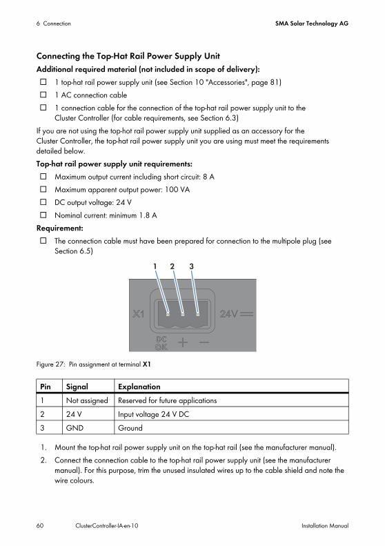
6 Connection SMA Solar Technology AG
60 ClusterController-IA-en-10 Installation Manual
Connecting the Top-Hat Rail Power Supply UnitAdditional required material (not included in scope of delivery):☐ 1 top-hat rail power supply unit (see Section 10 "Accessories", page 81)☐ 1 AC connection cable☐ 1 connection cable for the connection of the top-hat rail power supply unit to the
Cluster Controller (for cable requirements, see Section 6.3)If you are not using the top-hot rail power supply unit supplied as an accessory for the Cluster Controller, the top-hat rail power supply unit you are using must meet the requirements detailed below.Top-hat rail power supply unit requirements:☐ Maximum output current including short circuit: 8 A☐ Maximum apparent output power: 100 VA☐ DC output voltage: 24 V☐ Nominal current: minimum 1.8 A
Requirement:☐ The connection cable must have been prepared for connection to the multipole plug (see
Section 6.5)
Figure 27: Pin assignment at terminal X1
1. Mount the top-hat rail power supply unit on the top-hat rail (see the manufacturer manual).2. Connect the connection cable to the top-hat rail power supply unit (see the manufacturer
manual). For this purpose, trim the unused insulated wires up to the cable shield and note the wire colours.
Pin Signal Explanation1 Not assigned Reserved for future applications2 24 V Input voltage 24 V DC3 GND Ground
SMA Solar Technology AG 6 Connection
Installation Manual ClusterController-IA-en-10 61
3. Connect the connection cable to the three-pole plug as follows. For this purpose, release conductor entries 2 and 3 with a screwdriver and insert the insulated wires into the conductor entries. Observe the pin assignment.
4. Connect the three-pole plug to terminal X1 of the Cluster Controller.5. Connect the AC connection cable to the top-hat rail power supply unit (see the manufacturer
manual).
7. Connect the other end of the AC connection cable to the electricity supply.8. Connect the connection point to the electricity grid.
☑ The power LED ( ) of the Cluster Controller glows red for two seconds, then it permanently glows green. The status LED ( ) glows corresponding to the current device status (see Section 7.1 "LED States", page 65). The Cluster Controller is ready for operation after a maximum of one minute.
✖ Is the power LED ( ) glowing permanently red, the status LED ( ) glowing yellow or red and the Cluster Controller not starting?Possible fault cause: the voltage supply is too low. • Ensure that the voltage supply is sufficient (see Section 9 "Technical Data", page 77).• If the problem persists, contact the SMA Service Line (see Section 11).
6.14 Checking the Connections via the DisplayYou can use the display of the Cluster Controller to check whether the connections have been made correctly and whether all inverters, sensors and remote terminals have been detected by the Cluster Controller.
Procedure:• The display language can be changed via the user interface of the Cluster Controller if required.• Check the connections via the display.
6.Danger to life due to electric shockLethal voltages are present at the connection point of the electricity grid.
• Disconnect the connection point from the electricity grid using the separator (e.g. miniature circuit-breaker).
Available display languagesThe display languages of the Cluster Controller are German and English. The default language is English.
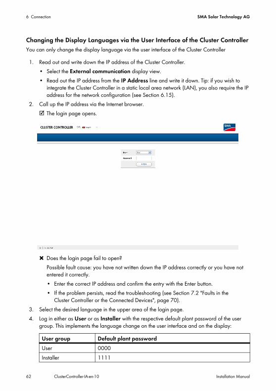
6 Connection SMA Solar Technology AG
62 ClusterController-IA-en-10 Installation Manual
Changing the Display Languages via the User Interface of the Cluster ControllerYou can only change the display language via the user interface of the Cluster Controller
1. Read out and write down the IP address of the Cluster Controller.• Select the External communication display view.• Read out the IP address from the IP Address line and write it down. Tip: if you wish to
integrate the Cluster Controller in a static local area network (LAN), you also require the IP address for the network configuration (see Section 6.15).
2. Call up the IP address via the Internet browser.☑ The login page opens.
✖ Does the login page fail to open?Possible fault cause: you have not written down the IP address correctly or you have not entered it correctly.• Enter the correct IP address and confirm the entry with the Enter button.• If the problem persists, read the troubleshooting (see Section 7.2 "Faults in the
Cluster Controller or the Connected Devices", page 70).3. Select the desired language in the upper area of the login page.4. Log in either as User or as Installer with the respective default plant password of the user
group. This implements the language change on the user interface and on the display:
User group Default plant passwordUser 0000Installer 1111
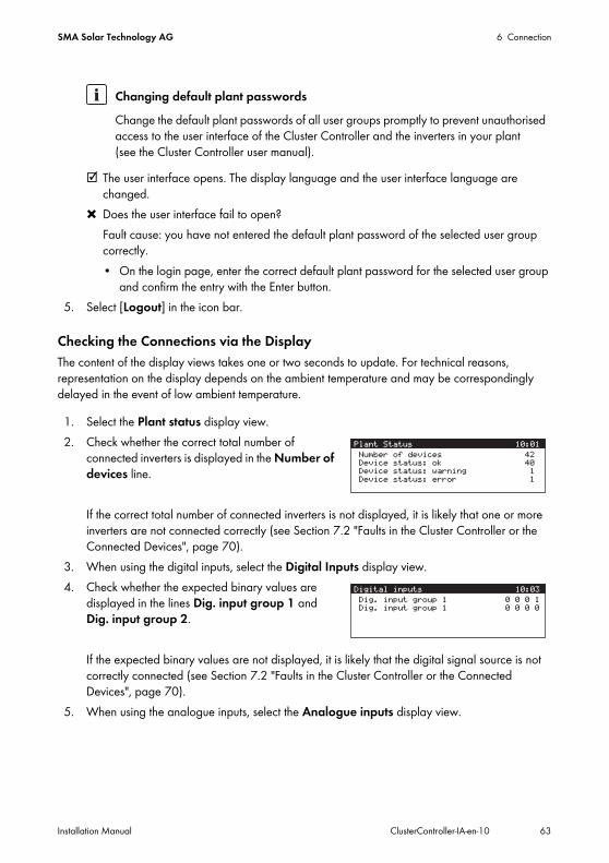
SMA Solar Technology AG 6 Connection
Installation Manual ClusterController-IA-en-10 63
☑ The user interface opens. The display language and the user interface language are changed.
✖ Does the user interface fail to open?Fault cause: you have not entered the default plant password of the selected user group correctly.• On the login page, enter the correct default plant password for the selected user group
and confirm the entry with the Enter button.5. Select [Logout] in the icon bar.
Checking the Connections via the DisplayThe content of the display views takes one or two seconds to update. For technical reasons, representation on the display depends on the ambient temperature and may be correspondingly delayed in the event of low ambient temperature.
1. Select the Plant status display view.2. Check whether the correct total number of
connected inverters is displayed in the Number of devices line.
If the correct total number of connected inverters is not displayed, it is likely that one or more inverters are not connected correctly (see Section 7.2 "Faults in the Cluster Controller or the Connected Devices", page 70).
3. When using the digital inputs, select the Digital Inputs display view.4. Check whether the expected binary values are
displayed in the lines Dig. input group 1 and Dig. input group 2.
If the expected binary values are not displayed, it is likely that the digital signal source is not correctly connected (see Section 7.2 "Faults in the Cluster Controller or the Connected Devices", page 70).
5. When using the analogue inputs, select the Analogue inputs display view.
Changing default plant passwordsChange the default plant passwords of all user groups promptly to prevent unauthorised access to the user interface of the Cluster Controller and the inverters in your plant (see the Cluster Controller user manual).
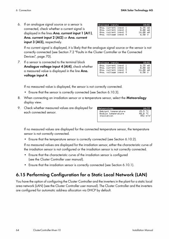
6 Connection SMA Solar Technology AG
64 ClusterController-IA-en-10 Installation Manual
6. If an analogue signal source or a sensor is connected, check whether a current signal is displayed in the lines Ana. current input 1 (AI1), Ana. current input 2 (AI2) or Ana. current input 3 (AI3), respectively.If no current signal is displayed, it is likely that the analogue signal source or the sensor is not correctly connected (see Section 7.2 "Faults in the Cluster Controller or the Connected Devices", page 70).
7. If a sensor is connected to the terminal block Analogue voltage input 4 (AI4), check whether a measured value is displayed in the line Ana. voltage input 4.
If no measured value is displayed, the sensor is not correctly connected.• Ensure that the sensor is correctly connected (see Section 6.10.3).
8. When connecting an irradiation sensor or a temperature sensor, select the Meteorology display view.
9. Check whether measured values are displayed for each connected sensor.
If no measured values are displayed for the connected temperature sensor, the temperature sensor is not correctly connected. • Ensure that the temperature sensor is correctly connected (see Section 6.10.2).If no measured values are displayed for the irradiation sensor, either the characteristic curve of the irradiation sensor is not configured or the irradiation sensor is not correctly connected.• Ensure that the characteristic curve of the irradiation sensor is configured
(see the Cluster Controller user manual).• Ensure that the irradiation sensor is correctly connected (see Section 6.10.1).
6.15 Performing Configuration for a Static Local Network (LAN)You have the option of configuring the Cluster Controller and the inverters in the plant for a static local area network (LAN) (see the Cluster Controller user manual). The Cluster Controller and the inverters are configured for automatic address allocation via DHCP by default.
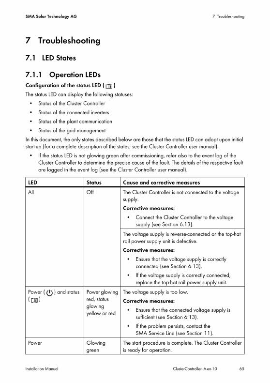
SMA Solar Technology AG 7 Troubleshooting
Installation Manual ClusterController-IA-en-10 65
7 Troubleshooting7.1 LED States
7.1.1 Operation LEDsConfiguration of the status LED ( )The status LED can display the following statuses:
• Status of the Cluster Controller• Status of the connected inverters• Status of the plant communication• Status of the grid management
In this document, the only states described below are those that the status LED can adopt upon initial start-up (for a complete description of the states, see the Cluster Controller user manual).
• If the status LED is not glowing green after commissioning, refer also to the event log of the Cluster Controller to determine the precise cause of the fault. The details of the respective fault are logged in the event log (see the Cluster Controller user manual).
LED Status Cause and corrective measuresAll Off The Cluster Controller is not connected to the voltage
supply.Corrective measures:
• Connect the Cluster Controller to the voltage supply (see Section 6.13).
The voltage supply is reverse-connected or the top-hat rail power supply unit is defective.Corrective measures:
• Ensure that the voltage supply is correctly connected (see Section 6.13).
• If the voltage supply is correctly connected, replace the top-hat rail power supply unit.
Power ( ) and status ( )
Power glowing red, status glowing yellow or red
The voltage supply is too low. Corrective measures:
• Ensure that the connected voltage supply is sufficient (see Section 6.13).
• If the problem persists, contact the SMA Service Line (see Section 11).
Power Glowing green
The start procedure is complete. The Cluster Controller is ready for operation.
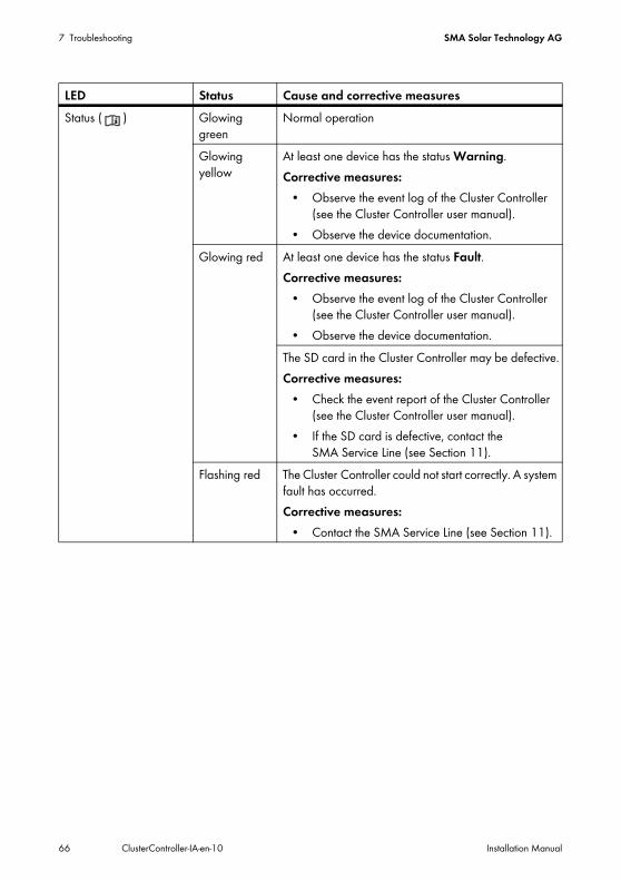
7 Troubleshooting SMA Solar Technology AG
66 ClusterController-IA-en-10 Installation Manual
Status ( ) Glowing green
Normal operation
Glowing yellow
At least one device has the status Warning.Corrective measures:
• Observe the event log of the Cluster Controller (see the Cluster Controller user manual).
• Observe the device documentation.Glowing red At least one device has the status Fault.
Corrective measures:• Observe the event log of the Cluster Controller
(see the Cluster Controller user manual).• Observe the device documentation.
The SD card in the Cluster Controller may be defective.Corrective measures:
• Check the event report of the Cluster Controller (see the Cluster Controller user manual).
• If the SD card is defective, contact the SMA Service Line (see Section 11).
Flashing red The Cluster Controller could not start correctly. A system fault has occurred.Corrective measures:
• Contact the SMA Service Line (see Section 11).
LED Status Cause and corrective measures
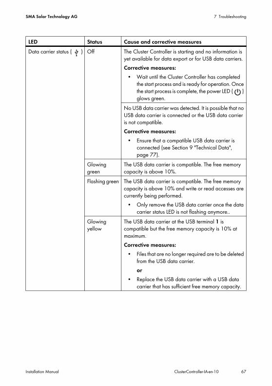
SMA Solar Technology AG 7 Troubleshooting
Installation Manual ClusterController-IA-en-10 67
Data carrier status ( ) Off The Cluster Controller is starting and no information is yet available for data export or for USB data carriers.Corrective measures:
• Wait until the Cluster Controller has completed the start process and is ready for operation. Once the start process is complete, the power LED ( ) glows green.
No USB data carrier was detected. It is possible that no USB data carrier is connected or the USB data carrier is not compatible.Corrective measures:
• Ensure that a compatible USB data carrier is connected (see Section 9 "Technical Data", page 77).
Glowing green
The USB data carrier is compatible. The free memory capacity is above 10%.
Flashing green The USB data carrier is compatible. The free memory capacity is above 10% and write or read accesses are currently being performed.
• Only remove the USB data carrier once the data carrier status LED is not flashing anymore..
Glowing yellow
The USB data carrier at the USB terminal 1 is compatible but the free memory capacity is 10% at maximum.Corrective measures:
• Files that are no longer required are to be deleted from the USB data carrier.or
• Replace the USB data carrier with a USB data carrier that has sufficient free memory capacity.
LED Status Cause and corrective measures
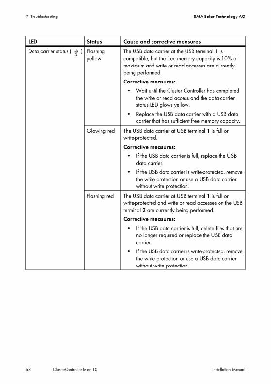
7 Troubleshooting SMA Solar Technology AG
68 ClusterController-IA-en-10 Installation Manual
Data carrier status ( ) Flashing yellow
The USB data carrier at the USB terminal 1 is compatible, but the free memory capacity is 10% at maximum and write or read accesses are currently being performed.Corrective measures:
• Wait until the Cluster Controller has completed the write or read access and the data carrier status LED glows yellow.
• Replace the USB data carrier with a USB data carrier that has sufficient free memory capacity.
Glowing red The USB data carrier at USB terminal 1 is full or write-protected.Corrective measures:
• If the USB data carrier is full, replace the USB data carrier.
• If the USB data carrier is write-protected, remove the write protection or use a USB data carrier without write protection.
Flashing red The USB data carrier at USB terminal 1 is full or write-protected and write or read accesses on the USB terminal 2 are currently being performed.Corrective measures:
• If the USB data carrier is full, delete files that are no longer required or replace the USB data carrier.
• If the USB data carrier is write-protected, remove the write protection or use a USB data carrier without write protection.
LED Status Cause and corrective measures
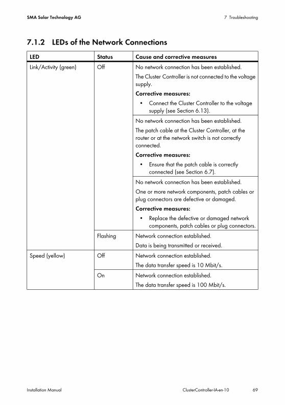
SMA Solar Technology AG 7 Troubleshooting
Installation Manual ClusterController-IA-en-10 69
7.1.2 LEDs of the Network ConnectionsLED Status Cause and corrective measuresLink/Activity (green) Off No network connection has been established.
The Cluster Controller is not connected to the voltage supply.Corrective measures:
• Connect the Cluster Controller to the voltage supply (see Section 6.13).
No network connection has been established.The patch cable at the Cluster Controller, at the router or at the network switch is not correctly connected.Corrective measures:
• Ensure that the patch cable is correctly connected (see Section 6.7).
No network connection has been established.One or more network components, patch cables or plug connectors are defective or damaged.Corrective measures:
• Replace the defective or damaged network components, patch cables or plug connectors.
Flashing Network connection established.Data is being transmitted or received.
Speed (yellow) Off Network connection established. The data transfer speed is 10 Mbit/s.
On Network connection established. The data transfer speed is 100 Mbit/s.
7 Troubleshooting SMA Solar Technology AG
70 ClusterController-IA-en-10 Installation Manual
7.2 Faults in the Cluster Controller or the Connected DevicesProblem Cause and corrective measuresThe Cluster Controller does not start. The LEDs and the display are off.
The Cluster Controller is not connected to the voltage supply.Corrective measures:
• Ensure that the three-pole plug for the voltage supply is connected to terminal X1 of the Cluster Controller.
The voltage supply is reverse-connected or the top-hat rail power supply unit is defective.Corrective measures:
• Ensure that the voltage supply is correctly connected (see Section 6.13).
• If the voltage supply is correctly connected, replace the top-hat rail power supply unit.
The login page does not open and the status LED ( ) flashes red.
The Cluster Controller could not start correctly. A system fault has occurred.Corrective measures:
• Disconnect the Cluster Controller from the voltage supply and reconnect to the voltage supply. Note that this can lead to loss of plant data.
• If the problem persists, contact the SMA Service Line (see Section 11).
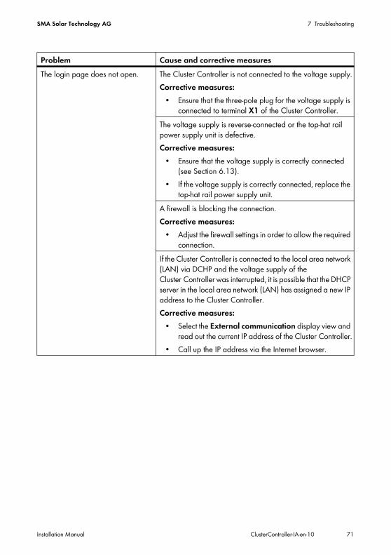
SMA Solar Technology AG 7 Troubleshooting
Installation Manual ClusterController-IA-en-10 71
The login page does not open. The Cluster Controller is not connected to the voltage supply.Corrective measures:
• Ensure that the three-pole plug for the voltage supply is connected to terminal X1 of the Cluster Controller.
The voltage supply is reverse-connected or the top-hat rail power supply unit is defective.Corrective measures:
• Ensure that the voltage supply is correctly connected (see Section 6.13).
• If the voltage supply is correctly connected, replace the top-hat rail power supply unit.
A firewall is blocking the connection.Corrective measures:
• Adjust the firewall settings in order to allow the required connection.
If the Cluster Controller is connected to the local area network (LAN) via DCHP and the voltage supply of the Cluster Controller was interrupted, it is possible that the DHCP server in the local area network (LAN) has assigned a new IP address to the Cluster Controller.Corrective measures:
• Select the External communication display view and read out the current IP address of the Cluster Controller.
• Call up the IP address via the Internet browser.
Problem Cause and corrective measures
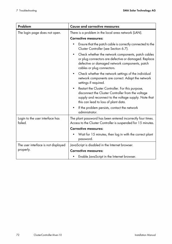
7 Troubleshooting SMA Solar Technology AG
72 ClusterController-IA-en-10 Installation Manual
The login page does not open. There is a problem in the local area network (LAN).Corrective measures:
• Ensure that the patch cable is correctly connected to the Cluster Controller (see Section 6.7).
• Check whether the network components, patch cables or plug connectors are defective or damaged. Replace defective or damaged network components, patch cables or plug connectors.
• Check whether the network settings of the individual network components are correct. Adapt the network settings if required.
• Restart the Cluster Controller. For this purpose, disconnect the Cluster Controller from the voltage supply and reconnect to the voltage supply. Note that this can lead to loss of plant data.
• If the problem persists, contact the network administrator.
Login to the user interface has failed.
The plant password has been entered incorrectly four times. Access to the Cluster Controller is suspended for 15 minutes. Corrective measures:
• Wait for 15 minutes, then log in with the correct plant password.
The user interface is not displayed properly.
JavaScript is disabled in the Internet browser.Corrective measures:
• Enable JavaScript in the Internet browser.
Problem Cause and corrective measures
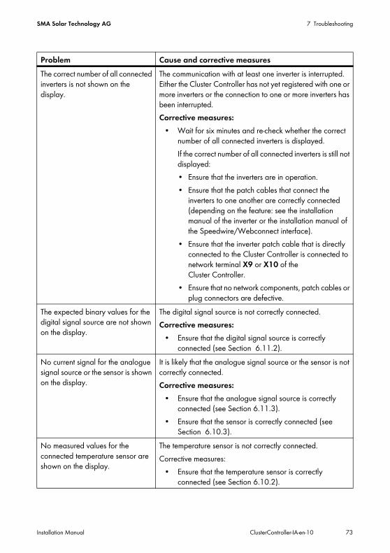
SMA Solar Technology AG 7 Troubleshooting
Installation Manual ClusterController-IA-en-10 73
The correct number of all connected inverters is not shown on the display.
The communication with at least one inverter is interrupted. Either the Cluster Controller has not yet registered with one or more inverters or the connection to one or more inverters has been interrupted.Corrective measures:
• Wait for six minutes and re-check whether the correct number of all connected inverters is displayed.If the correct number of all connected inverters is still not displayed:• Ensure that the inverters are in operation.• Ensure that the patch cables that connect the
inverters to one another are correctly connected (depending on the feature: see the installation manual of the inverter or the installation manual of the Speedwire/Webconnect interface).
• Ensure that the inverter patch cable that is directly connected to the Cluster Controller is connected to network terminal X9 or X10 of the Cluster Controller.
• Ensure that no network components, patch cables or plug connectors are defective.
The expected binary values for the digital signal source are not shown on the display.
The digital signal source is not correctly connected.Corrective measures:
• Ensure that the digital signal source is correctly connected (see Section 6.11.2).
No current signal for the analogue signal source or the sensor is shown on the display.
It is likely that the analogue signal source or the sensor is not correctly connected.Corrective measures:
• Ensure that the analogue signal source is correctly connected (see Section 6.11.3).
• Ensure that the sensor is correctly connected (see Section 6.10.3).
No measured values for the connected temperature sensor are shown on the display.
The temperature sensor is not correctly connected.Corrective measures:
• Ensure that the temperature sensor is correctly connected (see Section 6.10.2).
Problem Cause and corrective measures
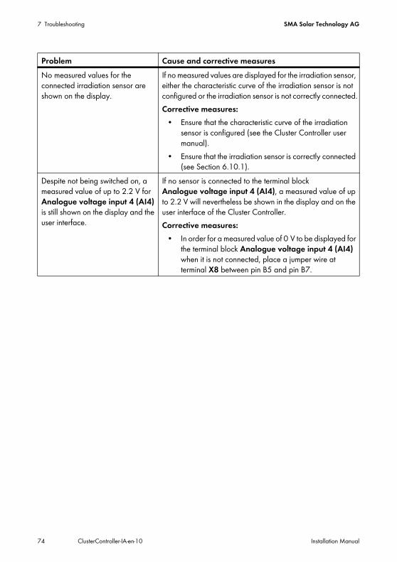
7 Troubleshooting SMA Solar Technology AG
74 ClusterController-IA-en-10 Installation Manual
No measured values for the connected irradiation sensor are shown on the display.
If no measured values are displayed for the irradiation sensor, either the characteristic curve of the irradiation sensor is not configured or the irradiation sensor is not correctly connected.Corrective measures:
• Ensure that the characteristic curve of the irradiation sensor is configured (see the Cluster Controller user manual).
• Ensure that the irradiation sensor is correctly connected (see Section 6.10.1).
Despite not being switched on, a measured value of up to 2.2 V for Analogue voltage input 4 (AI4) is still shown on the display and the user interface.
If no sensor is connected to the terminal block Analogue voltage input 4 (AI4), a measured value of up to 2.2 V will nevertheless be shown in the display and on the user interface of the Cluster Controller. Corrective measures:
• In order for a measured value of 0 V to be displayed for the terminal block Analogue voltage input 4 (AI4) when it is not connected, place a jumper wire at terminal X8 between pin B5 and pin B7.
Problem Cause and corrective measures
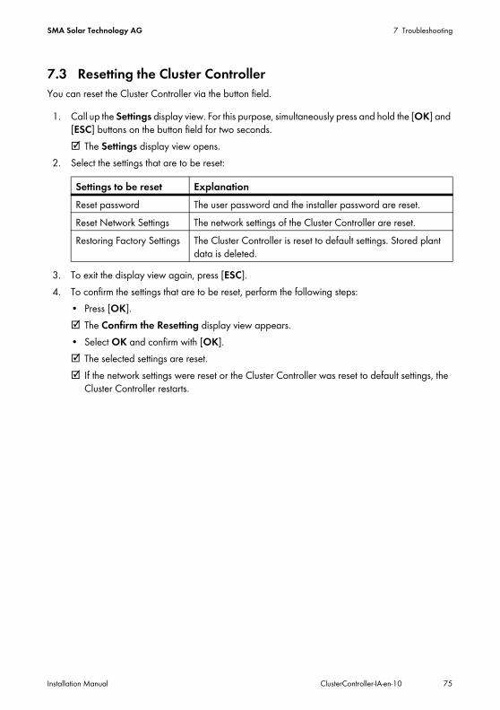
SMA Solar Technology AG 7 Troubleshooting
Installation Manual ClusterController-IA-en-10 75
7.3 Resetting the Cluster ControllerYou can reset the Cluster Controller via the button field.
1. Call up the Settings display view. For this purpose, simultaneously press and hold the [OK] and [ESC] buttons on the button field for two seconds.☑ The Settings display view opens.
2. Select the settings that are to be reset:
3. To exit the display view again, press [ESC].4. To confirm the settings that are to be reset, perform the following steps:
• Press [OK].☑ The Confirm the Resetting display view appears.• Select OK and confirm with [OK].☑ The selected settings are reset.☑ If the network settings were reset or the Cluster Controller was reset to default settings, the
Cluster Controller restarts.
Settings to be reset ExplanationReset password The user password and the installer password are reset.Reset Network Settings The network settings of the Cluster Controller are reset.Restoring Factory Settings The Cluster Controller is reset to default settings. Stored plant
data is deleted.
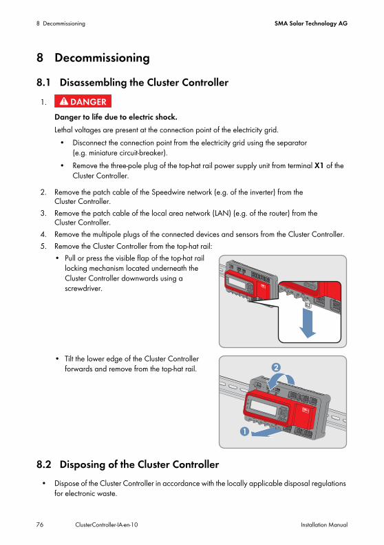
8 Decommissioning SMA Solar Technology AG
76 ClusterController-IA-en-10 Installation Manual
8 Decommissioning8.1 Disassembling the Cluster Controller
2. Remove the patch cable of the Speedwire network (e.g. of the inverter) from the Cluster Controller.
3. Remove the patch cable of the local area network (LAN) (e.g. of the router) from the Cluster Controller.
4. Remove the multipole plugs of the connected devices and sensors from the Cluster Controller.5. Remove the Cluster Controller from the top-hat rail:
• Pull or press the visible flap of the top-hat rail locking mechanism located underneath the Cluster Controller downwards using a screwdriver.
• Tilt the lower edge of the Cluster Controller forwards and remove from the top-hat rail.
8.2 Disposing of the Cluster Controller• Dispose of the Cluster Controller in accordance with the locally applicable disposal regulations
for electronic waste.
1.Danger to life due to electric shock.Lethal voltages are present at the connection point of the electricity grid.
• Disconnect the connection point from the electricity grid using the separator (e.g. miniature circuit-breaker).
• Remove the three-pole plug of the top-hat rail power supply unit from terminal X1 of the Cluster Controller.
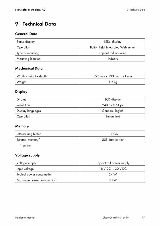
SMA Solar Technology AG 9 Technical Data
Installation Manual ClusterController-IA-en-10 77
9 Technical DataGeneral Data
Mechanical Data
Display
Memory
Voltage supply
Status display LEDs, displayOperation Button field, integrated Web serverType of mounting Top-hat rail mountingMounting location Indoors
Width x height x depth 275 mm x 133 mm x 71 mmWeight 1.2 kg
Display LCD displayResolution 240 px × 64 pxDisplay languages German, EnglishOperation Button field
Internal ring buffer 1.7 GBExternal memory*
* optional
USB data carrier
Voltage supply Top-hat rail power supplyInput voltage 18 V DC … 30 V DCTypical power consumption 24 WMaximum power consumption 30 W
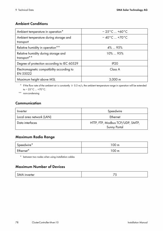
9 Technical Data SMA Solar Technology AG
78 ClusterController-IA-en-10 Installation Manual
Ambient Conditions
Communication
Maximum Radio Range
Maximum Number of Devices
Ambient temperature in operation*
* If the flow rate of the ambient air is constantly ≥ 0.5 m/s, the ambient temperature range in operation will be extended to − 25°C … +70°C.
− 25°C … +60°CAmbient temperature during storage and transport
− 40°C … +70°C
Relative humidity in operation**
** non-condensing
4% … 95%Relative humidity during storage and transport**
10% … 95%
Degree of protection according to IEC 60529 IP20Electromagnetic compatibility according to EN 55022
Class A
Maximum height above MSL 3,000 m
Inverter SpeedwireLocal area network (LAN) EthernetData interfaces HTTP, FTP, Modbus TCP/UDP, SMTP,
Sunny Portal
Speedwire*
* between two nodes when using installation cables
100 mEthernet* 100 m
SMA inverter 75
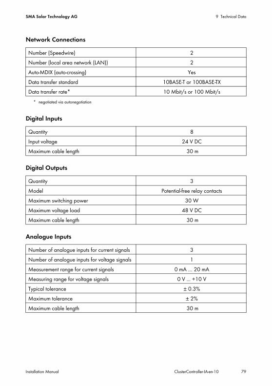
SMA Solar Technology AG 9 Technical Data
Installation Manual ClusterController-IA-en-10 79
Network Connections
Digital Inputs
Digital Outputs
Analogue Inputs
Number (Speedwire) 2Number (local area network (LAN)) 2Auto-MDIX (auto-crossing) YesData transfer standard 10BASE-T or 100BASE-TXData transfer rate*
* negotiated via autonegotiation
10 Mbit/s or 100 Mbit/s
Quantity 8Input voltage 24 V DCMaximum cable length 30 m
Quantity 3Model Potential-free relay contactsMaximum switching power 30 WMaximum voltage load 48 V DCMaximum cable length 30 m
Number of analogue inputs for current signals 3Number of analogue inputs for voltage signals 1Measurement range for current signals 0 mA … 20 mAMeasuring range for voltage signals 0 V ... +10 VTypical tolerance ± 0.3%Maximum tolerance ± 2%Maximum cable length 30 m
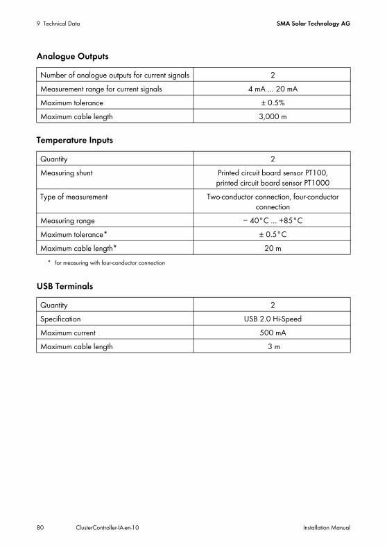
9 Technical Data SMA Solar Technology AG
80 ClusterController-IA-en-10 Installation Manual
Analogue Outputs
Temperature Inputs
USB Terminals
Number of analogue outputs for current signals 2Measurement range for current signals 4 mA … 20 mAMaximum tolerance ± 0.5%Maximum cable length 3,000 m
Quantity 2Measuring shunt Printed circuit board sensor PT100,
printed circuit board sensor PT1000Type of measurement Two-conductor connection, four-conductor
connectionMeasuring range − 40°C … +85°CMaximum tolerance*
* for measuring with four-conductor connection
± 0.5°CMaximum cable length* 20 m
Quantity 2Specification USB 2.0 Hi-SpeedMaximum current 500 mAMaximum cable length 3 m
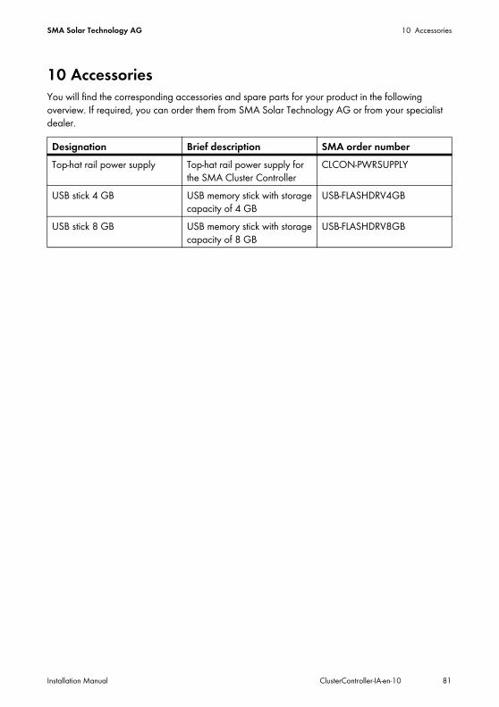
SMA Solar Technology AG 10 Accessories
Installation Manual ClusterController-IA-en-10 81
10 AccessoriesYou will find the corresponding accessories and spare parts for your product in the following overview. If required, you can order them from SMA Solar Technology AG or from your specialist dealer.
Designation Brief description SMA order numberTop-hat rail power supply Top-hat rail power supply for
the SMA Cluster ControllerCLCON-PWRSUPPLY
USB stick 4 GB USB memory stick with storage capacity of 4 GB
USB-FLASHDRV4GB
USB stick 8 GB USB memory stick with storage capacity of 8 GB
USB-FLASHDRV8GB
11 Contact SMA Solar Technology AG
82 ClusterController-IA-en-10 Installation Manual
11 ContactIf you have technical problems concerning our products, contact the SMA Service Line. We require the following information in order to provide you with the necessary assistance:
• Serial number and firmware version of the Cluster Controller• Type, serial number and firmware version of the inverter• When using a retrofitted Speedwire/Webconnect interface: serial number and firmware
version of the Speedwire/Webconnect interfaceYou can read out the necessary information via the user interface of the Cluster Controller (see the Cluster Controller user manual). Alternatively, you can also read out the serial number and the device type on the type label of the respective product (see the respective product manual). You can read out the serial number and the firmware version of the Cluster Controller on the Cluster Controller display view.
SMA Solar Technology AGSonnenallee 134266 Niestetal, Germanywww.SMA.de
SMA Service LineInverters +49 561 9522 1499Communication: +49 561 9522 2499Fax: +49 561 9522 4699E‑Mail: [email protected]
Legal Provisions SMA Solar Technology AG
83 ClusterController-IA-en-10 Installation Manual
Legal ProvisionsThe information contained in this document is the property of SMA Solar Technology AG. Publishing its content, either partially or in full, requires the written permission of SMA Solar Technology AG. Any internal company copying of the document for the purposes of evaluating the product or its correct implementation is allowed and does not require permission.
SMA Factory WarrantyThe current warranty conditions come enclosed with your device. These are also available online at www.SMA-Solar.com and can be downloaded and are available on paper from the usual sales channels if required.
Software LicensesThe licenses for the software modules used can be found on the CD provided.
TrademarksAll trademarks are recognized even if these are not marked separately. Missing designations do not mean that a product or brand is not a registered trademark.The Bluetooth® word mark and logos are registered trademarks owned by Bluetooth SIG, Inc. and any use of such marks by SMA Solar Technology AG is under licence.QR Code® is a registered trademark of DENSO WAVE INCORPORATED.
SMA Solar Technology AG Sonnenallee 1 34266 Niestetal GermanyTel. +49 561 9522-0 Fax +49 561 9522-100 www.SMA.de E-Mail: [email protected]© 2004 to 2013 SMA Solar Technology AG. All rights reserved

www.SMA-Solar.comSMA Solar Technology
SMA Solar Technology AGwww.SMA.deSMA Australia Pty. Ltd.www.SMA-Australia.com.auSMA Benelux bvba/sprlwww.SMA-Benelux.comSMA Beijing Commercial Company Ltd.www.SMA-China.com.cnSMA Central & Eastern Europe s.r.o.www.SMA-Czech.comSMA France S.A.S.www.SMA-France.comSMA Hellas AEwww.SMA-Hellas.comSMA Ibérica Tecnología Solar, S.L.U.www.SMA-Iberica.com
SMA Solar India Pvt. Ltd. www.SMA-India.comSMA Italia S.r.l.www.SMA-Italia.comSMA Japan K.K.www.SMA-Japan.comSMA Technology Korea Co., Ltd.www.SMA-Korea.comSMA Middle East LLC www.SMA-Me.comSMA Portugal - Niestetal Services Unipessoal Lda www.SMA-Portugal.comSMA Solar (Thailand) Co., Ltd.www.SMA-Thailand.comSMA Solar UK Ltd.www.SMA-UK.com