
SM8-TOP2_ISTR_EN-IT_6-1
128
MANUALE ISTRUZIONI INSTRUCTIONS MANUAL SM8-TOP2
-
Upload
telemaco2012 -
Category
Documents
-
view
238 -
download
0
Transcript of SM8-TOP2_ISTR_EN-IT_6-1

MANUALE ISTRUZIONI INSTRUCTIONS MANUAL
SM8-TOP2

SANTONI S.p.A.

SANTONI S.p.A.
REVISION 6.1
INSTRUCTIONS MANUAL FOR THE SM8-TOP2 MACHINE
MANUALE ISTRUZIONE PER MACCHINA SM8-TOP2
SM8-TOP2

SANTONI S.p.A.
REVISION 6.1

SANTONI S.p.A.
1
REVISION 6.1
GENERAL INDEX PREFACE 5 1 DESCRIPTION AND MAIN
CHARACTERISTICS 1.1 General information 6 1.2 Main characteristics 6 1.3 Knitting options 7 1.4 Optionals and variants 7 1.5 Machine consumption 7 1.6 Machine dimensions and weight 8 2 SAFETY 2.1 Regulations 11 2.2 Safety devices installed 14 2.3 Compliance statement 17 2.4 Risk prevention measures 18 2.5 Instructions and recommendations 21 2.6 Personal protection equipment 23 3 UNLOADING, DELIVERY AND
INSTALLATION 3.1 Machine delivery 24 3.2. Unpacking of machine 24 3.3 Assembly of parts 26 3.4 Cone holder creel 27 3.5 Connections 36 4 LUBRICATION AND PNEUMATIC
CONTROLS 4.1 Lubrication 38 4.2 Pneumatic control system 42 5 ADJUSTMENTS 5.1 Machine phases 55 5.2 Primary adjustments 65 5.3 Lower plate adjustment 66 5.4 Upper plate adjustment 70 5.5 Adjustment of sinker cap 85 5.6 Adjustment of the dial unit 90 6 REPLACEMENT OF FLAT PARTS 6.1 Replacement of dial jacks 97 6.2 Replacement of sinkers 99 6.3 Needle replacement 100 6.4 Jack replacement 102 6.5 Replacement of intermediate jacks 104 7 SUPPLIED INSTRUMENTS AND
CALIPER 7.1 Calipers supplied 105 7.2 Flat parts supplied 107 7.3 Mechanical parts supplied 115 7.4 Electrical parts supplied 116 7.5 Wrenches and pliers supplied 118
INDICE GENERALE PREFAZIONE 5 1 DESCRIZIONE E CARATTERISTICHE
GENERALI 1.1 Generalità 6 1.2 Caratteristiche generali 6 1.3 Possibilità tessili 7 1.4 Optionals e varianti 7 1.5 Consumi per macchina 7 1.6 Dimensioni e pesi 8 2 SICUREZZA 2.1 Norme di riferimento 11 2.2 Dispositivi di sicurezza installati 14 2.3 Dichiarazione di conformità 17 2.4 Soluzioni che il Cliente deve adottare 18 2.5 Istruzioni e raccomandazioni 21 2.6 Dispositivi di protezione individuale 23 3 SCARICO TRASPORTO
INSTALLAZIONE 3.1 Consegna della macchina 24 3.2 Come sballare la macchina 24 3.3 Montaggio particolari 26 3.4 Cantra porta rocche 27 3.5 Allacciamenti 36 4 LUBRIFICAZIONE E COMANDI
PNEUMATICI 4.1 Lubrificazione 38 4.2 Sistema comandi pneumatici 42 5 REGISTRAZIONI 5.1 Fasi macchina 55 5.2 Registrazioni primarie 65 5.3 Registrazioni piatto inferiore 66 5.4 Registrazione piatto superiore 70 5.5 Registrazione coperchio platine 85 5.6 Registrazione gruppo platorello 90 6 SOSTITUZIONE PARTI PIATTE 6.1 Sostituzione uncini 97 6.2 Sostituzione platine 99 6.3 Sostituzione aghi. 100 6.4 Sostituzione selettori 102 6.5 Sostituzione selettori intermedi: 104 7 DOTAZIONE ATTREZZI E CALIBRI 7.1 Calibri in dotazione 105 7.2 Dotazione parti piatte 107 7.3 Dotazione parti meccaniche 115 7.4 Dotazione parti elettriche 116 7.5 Dotazione chiavi e pinze 118

SANTONI S.p.A.
2
REVISION 6.1
8 KEYBOARD USE 8.1 Main window 121 8.2 Manual buttons 124 8.3 The “Clock” window 126 8.4 The “Production Data“ page 128 8.5 The Main Menu 131
8.5.1 The “General Utilities” page 133 8.5.2 The “Activate program” page 169 8.5.3 The “Activ. linking prg.” page 171 8.5.4 The “Size selection” page 173 8.5.5 The “Counter-p.Linking” page 175 8.5.6 The “Modify spandex“ page.” 196 8.5.7 The “Encoder zero pos.” page 202 8.5.8 The “Customer Set-up” page 205 8.5.9 The “Exter. Yarn feeder” page 224 8.5.10 The “Operations button” page 226 8.5.11 The “Execute autotest” page 233 8.5.12 The “Modify step savers” page 253 8.5.13 The “Variate speed” page 257 8.5.14 The “Modify yarn sensor” page 260 8.5.15 The “LVDT menu” page 279 8.5.16 The “Software version” page 288 8.5.17 The “Modify graduation” page 293
9 PROGRAMMING 9.1 A guide to machine data 295 9.2 Knitting basics 296
9.2.1 Knitting Basics 296 9.2.2 Knitting terry 300 9.2.3 Needle selection 302
9.3 Types of knitting 304 9.3.1 Plain stitch + bridle (float) 304 9.3.2 Plain stitch + bush (tuck) 308 9.3.3 Plain stitch + bridle (floated out of work,
jacquard) 312 9.3.4 Plain stitch of 2 colors plating on a
single background yarn + bridle (float) 316 9.3.5 Plain stitch of 2 colors plating on a
single background yarn + bush (tuck) 320 9.3.6 Plain stitch + bush (tuck) + bridle (float
out of work) 324 9.3.7 Sharp Pattern Fabric SM8-TOP2 328 9.3.8 Plain stitch of 3 colors on a single
background yarn + bridle (float) + bridle (float out of work) 332
9.3.9 Plain stitch of 3 colors on a single background yarn + bridle (float) + bush (tuck) 337
9.3.10 Plain stitch of 3 colors on a single background yarn + bridle (float out of work) + bush (tuck) 342
9.3.11 Print the manual working 347 9.4 Program header 348
9.4.1 Machine Type 349 9.4.2 Diameter machine 350
8 USO DELLA TASTIERA 8.1 La finestra principale 121 8.2 Tasti manuali 124 8.3 La finestra “Orologio” 126 8.4 La pagina “Dati di produzione” 128 8.5 Il Menu Gestione 131
8.5.1 La pagina “Utilità generali” 133 8.5.2 La pagina “Attiva programma” 169 8.5.3 La pagina “Attiva prg. concatenato” 171 8.5.4 La pagina “Seleziona taglia” 173 8.5.5 La pagina “Contacalze-Concatenato” 175 8.5.6 La pagina “Modifica elastico” 196 8.5.7 La pagina “Taratura zero mec.” 202 8.5.8 La pagina “Set-up cliente” 205 8.5.9 La pagina “Alimentatore ext. filo” 224 8.5.10 La pagina “Tasti Operativi” 226 8.5.11 La pagina “Autotest” 233 8.5.12 La pagina “Modifica economizzazioni” 253 8.5.13 La pagina “Modifica Velocità“ 257 8.5.14 La pagina “Modifica Scorrimento fili” 260 8.5.15 La pagina “Menu LVDT” 279 8.5.16 La pagina “Ver.sw macchina” 288 8.5.17 La pagina “Modifica restringimento” 293
9 PROGRAMMAZIONE 9.1 Guida dei dati macchina 295 9.2 Nozioni sulla maglia 298
9.2.1 Ciclo formazione maglia monofrontura 298 9.2.2 Ciclo di form. maglia a spugna monof. 301 9.2.3 Come avviene la selezione dei selettori 302
9.3 Tipi di lavorazioni 304 9.3.1 Maglia diritta + briglia (flottato) 304 9.3.2 Maglia diritta + boccola (trattenuto) 308 9.3.3 Maglia diritta più briglia (flottato fuori
lavoro, jacquard) 312 9.3.4 Maglia diritta a 2 colori in vanisè su
un filo di fondo + briglia (flottato) 316 9.3.5 Maglia diritta a 2 colori in vanisè su
un filo di fondo + boccola (trattenuto) 320 9.3.6 Maglia diritta + boccola (trattenuto) +
briglia (flottato fuori lavoro) 324 9.3.7 Maglia diritta con disegno nitido 328 9.3.8 Maglia diritta a 3 colori in vanisé su
un filo di fondo + briglia (flottato) + briglia (flottato fuori lavoro) 332
9.3.9 Maglia diritta a 3 colori in vanisé su un filo di fondo + briglia (flottato) + boccola (trattenuto) 337
9.3.10 Maglia diritta a 3 colori in vanisé su un filo di fondo + boccola (trattenuto) + briglia (flottato fuori lavoro) 342
9.3.11 Per stampare il manuale lavorazioni 347 9.4 Intestazione del programma 348
9.4.1 Tipo di macchina 349 9.4.2 Diametro 350

SANTONI S.p.A.
3
REVISION 6.1
9.4.3 Machine Needles 351 9.4.4 Needles of the Diagonal 354 9.4.5 Dial jack type 355 9.4.6 Oil Feeder 356 9.4.7 Oil Programming 357 9.4.8 Zero LVDT 358 9.4.9 LVDT Motor Position 359
9.5 Machine controls 360 9.5.1 Memo of the step 361 9.5.2 Economizers 363 9.5.3 Speed Ramp 367 9.5.4 Air Valve (VPE) 369 9.5.5 Functions 371 9.5.6 Position Functions 386 9.5.7 Yarnfingers 427 9.5.8 Special Functions 440 9.5.9 Pattern 489 9.5.10 Overlapping pattern 495 9.5.11 Selections (absolute, relative) 501 9.5.12 LVDT step motors 507
10 TROUBLESHOOTING 10.1 Preface 513 10.2 Description of the machine 513 10.3 Starting 514 10.4 Automatic resetting 515 10.5 Fan management 521 10.6 Air distribution valve management 521 10.7 Management of lubrication 521 10.8 Error messages alarms 522 10.9 Description of runner 2060-2063-2065 596 10.10 Description of serial outputs 597
10.10.1 List of solenoid valves External Bars and yarnfingers 598
10.11 Exclusion of the serial bars 616 10.11.1 Preliminary checks 616 10.11.2 Checking the serial bars 617 10.11.3 Serial line connection diagram 619
10.12 Machine set-up procedure with eprom 620 10.12.1 FLASH upgrading procedure with UP
point (one file only) 623 10.12.2 FLASH upgrading procedure with
Mach.bin (one file only) 625 10.12.3 FLASH upgrading procedure with
Pcb 2779 board (one file only) 627 10.13 Adjustment of the Pcb 966/1 and
Pcb 966/2 boards for PYF control machine SM8-TOP2 629
10.13.1 Table for Pcb 966/1 Regulation 630 10.13.2 Table for Pcb 966/2 Regulation 632 10.13.3 Position Jumper W23-W24 for
Pcb 966/1 and Pcb 966/2 634 10.14 Description of circuit boards 635
10.14.1 Front Apparatus Panel 637 10.14.2 Layout of Boards in the RACK - Front
Apparatus Panel 638 10.14.3 Side Power Panel 639
9.4.3 Aghi macchina 351 9.4.4 Diagonale selettori 354 9.4.5 Tipo uncino 355 9.4.6 Ciclo olio 356 9.4.7 Olio programmabile 357 9.4.8 Zero LVDT 358 9.4.9 Progr. quota sbilanciamento maglia 359
9.5 Comandi catena 360 9.5.1 Memo del passo 362 9.5.2 Economizzazioni 365 9.5.3 Rampa 368 9.5.4 Valvola parzializzatrice 370 9.5.5 Funzioni 371 9.5.6 Funzioni Posizione 386 9.5.7 Funzioni a posizione 427 9.5.8 Funzioni Speciali 440 9.5.9 Parametri inserimento disegno 489 9.5.10 Parametri inserimento dis. sovrapposto 495 9.5.11 Selezioni con program. ass. o relativa 501 9.5.12 Motori passo passo LVDT 507
10 RICERCA GUASTI 10.1 Prefazione 513 10.2 Descrizione macchina 513 10.3 Accensione 514 10.4 Azzeramento automatico 515 10.5 Gestione ventola 521 10.6 Gestione valvola parzializzatrice 521 10.7 Gestione lubrificazione 521 10.8 Errori allarmi 522 10.9 Descrizione errori azionamento runner
2060-2063-2065 596 10.10 Dercrizione uscite seriali 597
10.10.1 Elenco elettrovalvole Barre Esterne e guidafili 598
10.11 Procedura di esclusione barre seriali 616 10.11.1 Controlli preliminari 616 10.11.2 Controllo barre seriali 617 10.11.3 Schema collegamento linea seriale 619
10.12 Proc. di set-up m/c con reset eprom 620 10.12.1 Procedura aggiornamento FLASH con
punto UP (file unico) 623 10.12.2 Procedura aggiornamento FLASH con
Mach.bin (file unico) 625 10.12.3 Procedura aggiornamento FLASH con
scheda Pcb 2779 (file unico) 627 10.13 Regolazione Pcb 966/1 e Pcb 966/2 per
comando PYF m/c SM8-TOP2 629 10.13.1 Tabella per Regolazione Pcb 966/1 630 10.13.2 Tabella per Regolazione Pcb 966/2 632 10.13.3 Posizione Jumper W23-W24 per
Pcb 966/1 e Pcb 966/2 634 10.14 Descrizione schede 635
10.14.1 Pannello Anteriore Apparecchiatura 637 10.14.2 Disposizione Schede nel RACK - Pannello
Anteriore Apparecchiatura 638 10.14.3 Pannello laterale di Potenza 639

SANTONI S.p.A.
4
REVISION 6.1
10.14.4 Rear Apparatus Panel 640 10.14.5 Plate + Pcb2867/1 641 10.14.6 PYF Box 642 10.14.7 Pcb558A/4 - Overload Protection 643 10.14.8 Rack Panel Boards (rear view) 644 10.14.9 Pcb723A/1-2 - Power Group 645 10.14.10 Pcb775A/1 - Ceramic Power Supply
Board 646 10.14.11 Pcb950A/2 - Ceramic Outputs Board
Position : “A-B-C-D-E-F-G-H” RACK 648 10.14.12 Pcb952B/3 – LVDT Board
Position : “S” RACK 650 10.14.13 Control procedure of Errors MPP
(TOP2 – TOP2S) 653 10.14.14 Pcb958A/1 – Interface between
Board Pcb2004 and Bus Dinema Position : “Z” RACK 654
10.14.15 Pcb961A/1 – Step Motor Input Board Position : “V” RACK 655
10.14.16 Pcb963A/1 – Interface between Board Pcb2004 and Bus Dinema for the system Siemens/Argilon Position : “Z” RACK 656
10.14.17 Pcb966 – P.Y.F. Logic Board Position : “T” RACK 657
10.14.18 Pcb1084A – Upper Ventilator Control Board 659
10.14.19 Pcb1799B/1 – Stop-Start Board 660 10.14.20 Pcb1881A/1 – Board 16 Serial Outlets
for Expansion Boards 662 10.14.21 Pcb2004 – Master Board 663 10.14.22 Pcb2703B/1 – Serial IN-OUT Board 667 10.14.23 Pcb2706A/4 – F/V Converter Board 669 10.14.24 Pcb2714/1 – Serial Outputs Board
for Yarnfinger Groups 671 10.14.25 Pcb2724A/1 – V.P.E. Power Supply
Board 672 10.14.26 Pcb2737A/1 – Serial Outputs Board
for Solenoid Valve Bars 674 10.14.27 Pcb2751A/1 – Power Supply Circuit
Board 5-15-24V 675 10.14.28 Pcb2772C/1 – Driver for Mpp 677 10.14.29 Pcb2799A/1 – IN-OUT Board 679 10.14.30 Pcb2832/2 – Power Interface Board 680 10.14.31 Pcb2857/1 – Shelton device Board 681 10.14.32 Pcb2866/1 – Power Board Switching
2X24V with KTF device 682 10.14.33 Pcb2867/1 – Feeder Board Power
Siemens/Argilon system 683 10.14.34 Pcb3779/1 – Board Converter RS485
for LGL Devices 684 10.14.35 Pcb3779/2 – Board Converter RS485
for KTF Devices 685 10.14.36 Pcb3784/4 – Ceramic Outputs Board
Position: “A-B-C-D-E-F-G-H” RACK 686 10.15 KTF-Btsr Control module 688 10.16 Data Collection System 689
10.16.1 DCN 2000 689 10.16.2 Nautilus 695
10.14.4 Pannello Posteriore Apparecchiatura 640 10.14.5 Piastra + Pcb2867/1 641 10.14.6 Cassetta PYF 642 10.14.7 Pcb558A/4 - Protezione Sovratensioni 643 10.14.8 Schede Pannello Rack (vista posteriore)644 10.14.9 Pcb723A/1-2 - Gruppo Potenza 645 10.14.10 Pcb775A/1 – Scheda Alimentatore
Ceramiche 646 10.14.11 Pcb950A/2 – Scheda Uscite Ceramiche
Posizione : “A-B-C-D-E-F-G-H” RACK 648 10.14.12 Pcb952B/3 – Scheda LVDT
Posizione : “S” RACK 650 10.14.13 Procedura di controllo Errori MPP
(TOP2 – TOP2S) 653 10.14.14 Pcb958A/1 – Interfaccia tra scheda
Pcb2004 e Bus Dinema Posizione : “Z” RACK 654
10.14.15 Pcb961A/1 – Scheda Ingressi Mpp Posizione : “V” RACK 655
10.14.16 Pcb963A/1 – Interfaccia tra Scheda Pcb2004 e Bus Dinema per sistema Siemens/Argilon Posizione : “Z” RACK 656
10.14.17 Pcb966 – Scheda logica P.Y.F. Posizione : “T” RACK 657
10.14.18 Pcb1084A – Scheda Comando Ventilatore Superiore 659
10.14.19 Pcb1799B/1 – Scheda Marcia-Arresto 660 10.14.20 Pcb1881A/1 – Scheda 16 Uscite per
Espansione 662 10.14.21 Pcb2004 – Scheda Master 663 10.14.22 Pcb2703B/1 – Scheda IN-OUT Seriali 667 10.14.23 Pcb2706A/4 – Scheda Conv.re F/V 669 10.14.24 Pcb2714/1 – Scheda Uscite Seriali
Gruppi Guidafili 671 10.14.25 Pcb2724A/1 – Scheda Alim.ne V.P.E. 672 10.14.26 Pcb2737A/1 – Scheda Uscite Seriali
per Barre Elettrovalvole 674 10.14.27 Pcb2751A/1 – Scheda Alimentatore
5-15-24V 675 10.14.28 Pcb2772C/1 – Azionamento Mpp 677 10.14.29 Pcb2799A/1 – Scheda IN-OUT 679 10.14.30 Pcb2832/2 – Scheda Interfaccia
Potenza 680 10.14.31 Pcb2857/1 – Scheda Shelton 681 10.14.32 Pcb2866/1 – Scheda Alimentatore
Switching 2x24V con disp.KTF 682 10.14.33 Pcb2867/1 – Scheda Alimentatore
sistema Siemens/Argilon 683 10.14.34 Pcb3779/1 – Scheda Convertitore
RS485 per dispositivi LGL 684 10.14.35 Pcb3779/2 – Scheda Convertitore
RS485 per dispositivi KTF 685 10.14.36 Pcb 3784/4 Scheda Uscite Ceramiche
Posizione: “A-B-C-D-E-F-G-H“ RACK 686 10.15 Centralina KTF-Btsr 688 10.16 Sistema Raccolta Dati 689
10.16.1 DCN 2000 689 10.16.2 Nautilus 695

SANTONI S.p.A.
5
REVISION 6.1
PREFACE
Besides indicating and describing the machine various components, how they function and how they are to be used, this manual and its enclosures are to be used as the technical introduction to the running of a complex machine which, owing to its own nature, requires its proper use and maintenance. The good maintenance and the proper use of the machine will not only lengthen its overall life and guarantee its cost-effectiveness , but also enable it to reach the required levels of production, quality and safety. The instructions and warnings hereafter provided must not be considered as a long and useless list of warnings, but, on the contrary, as a series of instructions aimed at improving the machine performance in every sense and above all to avoid the injury of persons and the damaging of things owing to the improper usage of the machine. Note. The data provided in this manual are valid at the moment of its issuing. The SANTONI S.p.A. company reserves the right to modify the machine should it be deemed necessary to do so. The company excuses itself in advance should these changes not be immediately included in this manual.
PREFAZIONE La presente documentazione, oltre ad indicare ed illustrare le parti costituenti la macchina (loro funzione ed uso), sono un’introduzione tecnica alla conduzione di una macchina complessa che per sua stessa natura comporta un uso ed una manutenzione adeguata. Infatti, una buona manutenzione ed un appropriato uso oltre ad allungare la vita complessiva della macchina, e quindi a garantire il rientro economicoa, garantisce il mantenimento del livello di produttività e qualità, nonché quello sicurezza. Quanto di seguito indicato, quindi, non deve essere considerato come un lungo ed oneroso elenco di avvertenze, bensì come una serie d’istruzioni atte a migliorare in tutti i sensi le prestazioni della macchina e ad evitare soprattutto il succedersi di danni a persone o cose derivanti da procedure d’uso e di conduzioni scorrette Nota. I dati riportati su questo libro sono validi al momento della sua stesura, la ditta SANTONI S.p.A. si riserva la facoltà di poter apportare modifiche alla macchina qualora se ne verifichi la necessità. Ci scusiamo anticipatamente se queste non vengono tempestivamente segnalate su questo libro.

SANTONI S.p.A.
6
REVISION 6.1
1 DESCRIPTION AND MAIN CHARACTERISTICS
1.1 General information Usage and maintenance manual for a fully electronic 8 feed monocylinder circular knitting machine for the manufacturing of underwear for men – women – children. The cylinder diameter ranges from 12” to 16”. See pag. 10 for gauges and number of needles.
1.2 Main characteristics
The machine is fitted with an electronic system of the latest design and with a microprocessor unit. It is completely optoinsulated and it can be powered separately by means of a BRUSHLESS motor. Protection against E.M.I. with mains wires and lighting by means of suppressers. The machine has a LCD type display with 16 reading lines for detailed display of the following data: Machine stopping causes Programd and actual speed Number of garments programmed and
produced Program in progress and its phases Option to vary economizations, speed and
sizes Programming can be carried out by means
of Digraph 3 Plus, with direct transfer to the machine o with a FDU reader
An auto-test system enables the machine to check the output of the single electronic functions as well as to aadjust them.
8 stitch feeds 16 needle needle selection units, 2 per
feed, each with 16 selection levers Max speed: 110 rpm (Cylinder diameter 13”) Knit passage control by means of a
photocell Electronically controlled yarn fingers: 6+2
per colour for each feed 4 air pipes for thread suction including the
relative yarn cutter equipped with cleaning air-jet
cylinder rotation driven a Brushless motor Programmable integral lubrication with
recycle Rapid automatic machine resetting Cone holders with tailing Electronic partializing valve 8 IRO SFE yarn turners
1 DESCRIZIONE E CARATTERISTICHE GENE-RALI
1.1 Generalità Manuale d’uso e manutenzione per macchina circolare monocilindro, completamente elettronica a 8 alimentazioni per la produzione di capi per maglieria intima uomo – donna – bambino. Diametro cilindro da 12” a 16”. Per finezze e numero aghi. Vedi pag. 10
1.2 Caratteristiche generali Equipaggiata con apparecchiatura elettronica di recentissima concezione, realizzata con sistema a microprocessore, totalmente optoisolata, con possibilità di alimentazione separata tramite motore BRUSHLESS. Protezione contro E.M.I. con fili rete e scariche atmosferiche per mezzo di soppressori. Il display è del tipo LCD con 16 righe di lettura per la visualizzazione in esteso di: Cause arresto macchina Velocità programmata e reale Numero di capi programmati e prodotti Programma in corso e sue fasi Possibilità di variare economizzazioni,
velocità e taglie Programmazione tramite Digraph 3 Plus,
con trasferimento diretto alla macchina, o con lettore FDU
Un sistema di auto-test consente la verifica delle uscite delle singole funzioni elettroniche, nonché la regolazione delle stesse
8 cadute di maglia 16 gruppi selezione ago/ago 2 per caduta
ciascuno con 16 leve selettrici Velocità max: 110 giri 1’ (Diametrocilindro 13”) Controllo passaggio maglia con fotocellula Guidafili a comando elettronico: 6+2 per
colore per ogni caduta 4 bocchette per aspirazione fili con relativo
coltellino rasafili dotato di soffio per pulizia la rotazione del cilindro avviene tramite
motore Brushless lubrificazione integrale a riciclo d’olio
programmabile Azzeramento macchina rapido ed
automatico Portarocche con testa-coda Valvola parzializzatrice elettronica N°8 Fornitori filo IRO SFE

SANTONI S.p.A.
7
REVISION 6.1
2 KTF/50HPS feeders for spandex cuff 8 KTF/25HPS feeders for elastomers Thread collector filter 8 LGL SMART feede
1.3 Knitting options
Electronic needle/needle selection (2 actuators per feed)
Electronic controlled stitch regulation by means of an independent step motor on each feed (with possible rapid stretching or shrinkage on every row
A number of models can be saved, each in 8 different sizes
Double edges or belts can be produced with a single dial jack in various models either with woven or knitted elastics
Knits with three techniques: tucked, floated, woven, possibility of colours and reinforcement. Terry (upon request) in gauges 22-24-26-28 (excluding 16-32).
Yarns: cotton, nylon and elastic yarns with various possibilities of plating
1.4 Optionals and variants Plate opener for feeder n. 5 Ring for article collector bag ELAN 2 device (4 or 8) for bare Lycra Double control on yarn finger n. 4 Rubber pliers on feeders n. 4 and 8 Fine-toothed saw (standard equipment on
32 gauge) Yarn fingers n. 4, 5, 6, with a 1.3 Ø hole Suction fan KTF25HPS feeder for covered Lycra (8) 8 extra LGL SMART feeders “ROJ-
TRICOT” (888 or 16) Electronic spandex dispenser, feeds n. 2
and 6 Terry kit (excluding 16-32 gauge) Rotating vacuum pipe
1.5 Machine consumption Intake air
consumption Thread suction device draft
800mm water column (tube with internal Ø of 10 mm)
Item draft 800mm water column (tube with internal Ø of 10 mm)
Consumption of intake air at thread suction device ~ 6 m³ per minute
N°2 Alimentatori KTF/50HPS per bordo elastico
N°8 Alimentatori KFT/25HPS per elastomeri Filtri raccogli filo N° 8 Alimentatori LGL. SMART
1.3 Possibilità tessili
Selezione elettronica ago/ago (2 attuatori per caduta)
Regolazione maglia a comando elettronico tramite motore passo-passo indipendente su ogni caduta (con possibilità di allargamento o restringimento rapido su ogni rango)
Possibilità di memorizzare più articoli in 8 taglie ciascuno
Bordo o cintura doppi, realizzati con uncino singolo, in diverse selezioni, con elastico immagliato o tramato
Maglia a tre vie tecniche: trattenuta, flottata, jacquard, tramata, possibilità di colori e rinforzi. Spugna (a richiesta) per finezze 22-24-26-28 (esclusa 16-32).
Filati: cotone, nylon e filati elasticizzati, con varie possibilità di vanisé
1.4 Optionals e varianti
Apri piattello 5° alimentazione Anello per sacco raccogli articoli Dispositivo ELAN 2 (4 o 8) per Lycra nudo Pinza gomma su 4° e 8° alimentazione Seghetta a denti fini (di serie su fin.32) Guidafili n°4-n°5-n°6 con foro Ø1,3 Ventole di aspirazione Alimentatore KTF25/HPS per Lycra
ricoperto (8) N° 8 alimentatori LGL SMART suppl. “ROJ-
TRICOT” (8 o 16) Fornitore elettronico per elastico 2ª 6ª
alimentazione. Kit spugna (esclusa finezza 16-32) Tubo di aspirazione di tipo rotante
1.5 Consumi per macchina Consumi di aria aspirazione Tiraggio bocchette aspirafili
800mm colonna d’acqua (con tubo Ø interno 10mm)
Tiraggio pezzo 800mm colonna d’acqua (con tubo Ø interno 10mm)
Consumo aria aspirazione da bocchette ~ 6 m³ al minuto

SANTONI S.p.A.
8
REVISION 6.1
Consumption of intake air at cylinder ~ 4 m³
per minute Compressed air consumption Compressed air at 6bar, with 0° humidity and a temperature of 20° at the dryer exit Consumption
~ 50 L/min. Installed power Motor: kW 2,2 ~ Fans: kW 3,9 ~
Power dissipated in heat • Motor 9900 BTU/h • Fans 10300 BTU/h
1.6 Machine dimensions and weight See Fig. 1-6 Overall dimensions with cone holders
mm 2600x3000x2850 Overall dimensions of machine frame (Fig.
3-2) mm 1150x1300x2080
Net machine weight Kg 600
Gross machine weight Kg 750
Weight of suction fans (optionals) Kg 50
PYF 4 device weight (optionals) ~ Kg 10
PYF 8 device weight (optionals) ~ Kg 20
Cone holders frame overall dimensions mm 2790x890x660
Net cone holders weight Kg 64
Gross cone holders weight (including IRO feeders) Kg 170
Consumo aria aspirazione da cilindro ~ 4 m³ al minuto
Consumo aria compressa Aria compressa a 6bar con umidità 0° e temperatura uscita essiccatore 20° Consumo
~ 50 L/min. Potenza installata Motore KW 2,2 ~ Ventole KW 3,9 ~
Potenza dissipata in calore • Motore 2500 cal/h • Ventole 2600 cal/h
1.6 Dimensioni e pesi Vedi Fig. 1-6 Ingombro macchina con portarocche
mm 2600x3000x2850 Ingombro cassa macchina (Fig. 3-2)
mm 1150x1300x2080 Peso netto macchina
Kg 600 Peso lordo macchina
Kg 750 Peso ventole aspirazione (optionals)
Kg 50 Peso dispositivo PYF 4 (optionals)
~ Kg 10 Peso dispositivo PYF 8 (optionals)
~ Kg 20 Ingombro cassa portarocche
mm 2790x890x660 Peso netto portarocche
Kg 64 Peso lordo portarocche (compresi gli IRO)
Kg 170

SANTONI S.p.A.
9
REVISION 6.1
Fig. 1-6

SANTONI S.p.A.
10
REVISION 6.1
Table of gauges and counts Tabella finezze e divisioni
Needle gauge Finezza ago
GG 48
Needle gauge Finezza ago
GG 54
Needle gauge Finezza ago GG 70
Needle gauge Finezza ago
GG 75
MACHINE GAUGE FINEZZA MACCHINA
Ø CYLINDER CILINDRO
16 22 24 26 28 32
12” 592 816* 912 960 1056 1024* 1200
13” 640 912* 960 1056 1152 1296
14” 688 704* 960* 1056 1152 1248
1216* 1392
15” 736 1056* 1136* 1248 1344 1280* 1488
16” 800 1104* 1216* 1296 1344*
1392 1440* 1584
*Needle counts on request Other needle counts on request
* Divisioni a richiesta Altre divisioni a richiesta

SANTONI S.p.A.
11
REVISION 6.1
2 SAFETY
2.1 Regulations The SM8-TOP2 knitting machine was designed and built in compliance with the existing Italian legislation and EC directives on safety and hygiene in the workplace hereafter listed:
2.1.1 Legislation. Italian Presidential Decree 547/55:
Regulation on the prevention of accidents in the workplace;
Italian Presidential Decree 303/65: General regulation on hygiene in the workplace;
Law 791/77: Implementation of the European directive on safety warranties for electrical material which is to be used within specific voltage limits;
Italian Legislative Decree 277/91: Implementation of European directives on the protection of workers against the risks deriving from exposure to asbestos, lead and noise;
Italian Legislative Decree 475/92: Implementation of the European directive on personal protection equipment;
Italian Legislative Decree 493/96: Implementation of the European directive on safety and/or health precautions signs in the workplace;
Italian Presidential Decree 459/96: Implementation of European directives on the improvement of the safety of machines;
EN50081-2: General rule on emissions into industrial environments;
EN55011: Basic rule class A group 1;
2.1.2 Technical rules applied in building the
machine: In compliance with the wording of the Machine Directive and the Italian Presidential Decree 459/96, all the envisaged requirements and solutions aimed at preventing risks and hazards to the safety of the operators were adopted:
2 SICUREZZA
2.1 Norme di riferimento La macchina per maglieria tipo SM8-TOP2, è stata progettata e costruita in conformità alla vigente Legislazione Nazionale ed alle Direttive Comunitarie in materia di sicurezza e igiene sul lavoro, di seguito elencate:
2.1.1 Norme di legge.
D.P.R. 547/55: Norme per la prevenzione degli infortuni sul lavoro;
D.P.R. 303/65: Norme generali per l’igiene del lavoro;
Legge 791/77: Attuazione direttiva europea in materia di garanzie di sicurezza che deve possedere il materiale elettrico che deve essere usato entro alcuni limiti di tensione;
D. Lgs. 277/91: Attuazioni direttive europee in materia di protezione dei lavoratori contro i rischi derivanti da esposizione all’amianto, al piombo e al rumore;
D. Lgs. 475/92: Attuazione direttiva europea in materia di dispositivi di protezione individuale;
D. Lgs. 493/96: Attuazione della direttiva europea concernente le prescrizioni le precauzioni minime per la segnaletica di sicurezza e/o di salute sul luogo di lavoro;
D.P.R. 459/96: Attuazione direttive europee riguardanti il miglioramento della sicurezza delle macchine;
EN50081-2: Norma generica emissione ambiente industriale;
EN55011: Norma di base classe A gruppo 1;
2.1.2 Norme tecniche adottate per la costruzione della macchina: Facendo riferimento al dettato dalla Direttiva Macchina e al DPR 459/96, per la macchina in oggetto, sono stati presi in considerazione tutti i requisiti indicati dalla Direttiva stessa e adottate quindi le soluzioni atte a prevenire i rischi per gli operatori:
SANTONI S.p.A.
12
REVISION 6.1
Said requirements are listed below together with the Reference regulations: Safety integration principles (EN 292-1/2 – pr. EN 1050) Materials and products (EN 292-2 EN 626-1 EN 982) Designing of machine for transportation purposes (EN 292-2) Controls
Control systems safety and reliability (EN 292-2 pr. EN 594-1)
Control devices (EN 292-2 - EN 418) Starting (EN 292-2 – EN 1037) Stop devices (EN 292-2 – EN418) Function mode selector (EN 292-2) Control circuit malfunction (EN292-2 –
EN 1037) Software (EN 292-2)
Safety measures against risks posed by mechanical devices
Stability (EN 292-2) Risk of breaking while functioning (EN
292-2) Risks posed by the fall and ejection of
objects (EN 292-2) Risks posed by surfaces, edges and
angles (EN 292-2) Prevention of risks posed by moving
parts (EN 292-2) Choice of safety devices against the
risks posed by moving parts (EN 292-2) Minimum distance to avoid crushing of
parts of the human body (EN 349) Requirements for protection equipment
General requirements (EN 292-2– EN294)
Fixed protections (EN 292-2) Interblocking devices for safety guards
(EN 1088)
Si elencano qui di seguito tali requisiti, con l’indicazione delle Norme di riferimento: Principi d’integrazione della sicurezza (EN 292-1/2 – pr. EN 1050) Materiale e prodotti (EN 292-2 EN 626-1 EN 982) Progettazione della macchina ai fini del trasporto (EN 292-2) Comandi
Sicurezza e affidabilità dei sistemi di comando (EN 292-2 pr. EN 594-1)
Dispositivi di comando (EN 292-2 - EN 418)
Avviamento (EN 292-2 – EN 1037) Dispositivi di arresto (EN 292-2 –
EN418) Selettore modale di funzionamento (EN
292-2) Avaria del circuito di comando (EN292-
2 – EN 1037) Software (EN 292-2)
Misure di protezione contro i rischi meccanici
Stabilità (EN 292-2) Rischio di rottura durante il
funzionamento (EN 292-2) Rischi dovuti alla caduta e alla
proiezione di oggetti (EN 292-2) Rischi dovuti a superfici, spigoli ed
angoli (EN 292-2) Prevenzione dei rischi dovuti agli
elementi mobili (EN 292-2) Scelta di una protezione contro i rischi
dovuti agli elementi mobili (EN 292-2) Spazi minimi per evitare lo
schiacciamento di parti del corpo umano (EN 349)
Caratteristiche richieste per le protezioni ed i dispositivi di protezione
Requisiti generali (EN 292-2– EN294) Protezioni fisse (EN 292-2) Dispositivi di interblocco associati ai
ripari (EN 1088)

SANTONI S.p.A.
13
REVISION 6.1
Safety measures against other risks
Risks posed by electricality (EN292-2) Radiation, radio frequencies and
magnetic fields pollution (directive 89/336/CEE)
Risks posed by improper assembly (EN 292-2)
Safety of machines’ electrical equipment (CEI EN 60204-1)
Risks posed by noise (EN 292-2-D.Lgs. 277/91 – UNI 7712)
Risks posed by the noise produced (Council Directive 89/188/CEE)
Maintenance
Machine maintenance (EN 292-2) Insulation from power supply sources
(EN 292-2) Operator intervention (EN 292-2)
Signals
Information devices (EN 292-2) Safety signs in the workplace (Italian
Legislative Decree 524/82) Alarm devices (EN 292-2) Safety signs (79/640/CEE – 92/58/CEE) Implementation of the European
directive on safety and/or health precautions signs in the workplace (Italian Legislative Decree 493/96)
Residual hazards warnings Marking Use instructions (EN 292-2)
Other rules
Textile machines safety requirements (UNI EN ISO 11111)
Risk assessment (UNI EN 1050 – UNI EN 954)
Implementation of the European directive on personal protection equipment (Italian Legislative Decree 475/92)
Personal protection equipment (89/656/CEE–89/686/CEE-93/95CEE)
Prevention of accidents in the workplace Electrical systems and material
(Directive 73/23/CEE)
Misure di protezione contro altri rischi
Rischi dovuti all’energia elettrica (EN292-2)
Inquinamento da radiazioni, radio fre-quenze e campi magnetici (direttiva 89/336/CEE)
Rischi dovuti a errori di montaggio (EN 292-2)
Sicurezza del macchinario equipag-giamento elettrico delle macchine (CEI EN 60204-1)
Rischi dovuti al rumore (EN 292-2-D.Lgs. 277/91 – UNI 7712)
Rischio causato dal rumore prodotto (Direttiva del Consiglio 89/188/CEE)
Manutenzione
Manutenzione della macchina (EN 292-2)
Isolamento dalle fonti di alimentazione di energia (EN 292-2)
Intervento dell’operatore (EN 292-2) Segnalazioni
Dispositivi di informazione (EN 292-2) Segnaletica di sicurezza sul posto di
lavoro (D.Lgs. 524/82) Dispositivi di allarme (EN 292-2) Cartellonistica di sicurezza
(79/640/CEE – 92/58/CEE) Attuazione della direttiva europea con-
cernente le prescrizioni minime per la segnaletica di sicurezza e/o di salute sul luogo di lavoro (D.Lgs.493/96)
Avvertenze in merito ai rischi residui Marcatura Istruzioni per l’uso (EN 292-2)
Altre norme
Requisiti di sicurezza per macchinario tessile (UNI EN ISO 11111)
Stima del rischio (UNI EN 1050 – UNI EN 954)
Attuazione direttiva europea in materia di dispositivi di protezione individuale (D.Lgs. 475/92)
Dispositivi di protezione individuale (89/656/CEE–89/686/CEE-93/95CEE)
Prevenzione degli infortuni sul lavoro Impianti e materiale elettrici (Direttiva
73/23/CEE)

SANTONI S.p.A.
14
REVISION 6.1
2.2 Safety devices installed
1. Mushroom push button for emergency
stop 2. Red light for emergency signals. 3. Opening device with special key to gain
access to electrical equipment. 4. Hinged electrical equipment closet
providing access to the mechanical parts. 5. Base with slots for the safe transporting
of the machine. 6. Interblocking micro-switch in case of
opening the door. 7. PROG-AUTO-MAN mode selector with
key 8. 3 mobile safety guards of the appropriate
height and with interblocking micro-switch.
9. 2 micro-switches for dial in high and low
position. 10. Main switch with blocking device for
electrical equipment door. 11. Hinged electrical equipment closet
providing access to the inside of the machine with screw-fastened doors.
12. Door fastening screws.
2.2 Dispositivi di sicurezza installati 1. Pulsante a fungo per fermata
d’emergenza. 2. Lampada di colore rosso per
segnalazione d’emergenza. 3. Dispositivo di apertura con chiave
speciale per accedere ad apparecchiatura elettrica.
4. Armadio apparecchiature elettriche e
incernierato per consentire l’accesso ad organi meccanici.
5. Zoccolo con tasche per effettuare il
trasporto in sicurezza. 6. Microinterruttore di interblocco in caso di
apertura dello sportello. 7. Selettore di modo PROG-AUTO-MAN
con chiave. 8. N°3 ripari mobili di altezza adeguata con
microinterruttore di interblocco. 9. N°2 micro per posizione plato alto e plato
basso. 10. Interruttore generale con dispositivo di
blocco sportello apparecchiatura elettrica.
11. Armadi elettrici incernierati per accedere
all’interno della macchina, con sportelli fissati con viti.
12. Viti fissaggio sportello.

SANTONI S.p.A.
15
REVISION 6.1
Fig. 2-3
The machine is equipped with the following safety devices for the operator: 2.2.1 Mobile safety guards located near
the moving parts of the threading unit and complete with control micro-switches; the removal of one of the safety guards in compact polycarbonate immediately makes the machine stop. Press the [F8] key to cancel the error and then press the speed button to start the machine again.
2.2.2 Doors fastened with screws or with
other devices requiring special means for their opening and located on the base of the machine to protect the electrical equipment and the moving parts.
2.2.3 Safety guard in compact
polycarbonate screwed onto the front part of the integral feeder parts to protect the moving parts.
La macchina dispone delle seguenti protezioni per il lavoratore addetto: 2.2.1 Ripari mobili, posizionati intorno agli
organi in movimento di filatura, completi di microinterruttori di controllo; l’estrazione dalla propria sede di uno dei ripari, realizzati in policarbonato compatto, determina l’arresto immediato della macchina. Per riavviare la macchina premere il tasto [F8] per cancellare l’errore, quindi premere il pulsante di marcia.
2.2.2 Sportelli fissati con viti, o con
dispositivi che richiedono dotazioni particolari per la loro apertura, posti sul basamento della macchina a protezione delle apparecchiature elettriche e degli organi del moto.
2.2.3 Riparo in policarbonato compatto,
fissato con viti posto sul fronte degli organi alimentatori integrali a protezione degli organi in movimento.

SANTONI S.p.A.
16
REVISION 6.1
2.2.4 Manual rotation with the knob is
possible only when the machine is still.
2.2.5 Emergency stop mushroom push
button. 2.2.6 Selector with removable key to avoid
the execution in manual mode of operations to be carried out by maintenance operators or by the person in charge.
2.2.7 Suction of oil mist together with cut,
sheared and missed threads into the filter of the suction system.
2.2.8 Preliminary operations for the
installation of the supplementary suction system to be positioned outside the machine.
2.2.9 Fixed safety guard on machine edge
horizontal support to guarantee the complete protection of moving parts.
2.2.10 Dial jack dial and yarn cutter saw
control device; the manual lifting of the machine edge horizontal unit (dial and saw) is operated by an electronic control placed on the machine; the command can only be activated when the machine is idle.
The machine is equipped with the following safety devices for the protection of the maintenance operator: 2.2.11 Machine functioning without the
safety guards by means of the sustained speed button. This operation is possible only when the key mode selector is in MANUAL position. The key is to be kept in a safe place by either the maintenance operator or the person in charge.
2.2.12 When the electrical equipment
cabinet is open, the moving and transmission parts are protected by safety guards in compact polycarbonate fastened to the base with screws and equipped with interblocking micro-switches.
2.2.4 La rotazione manuale con manovella elettronica è possibile solo a macchina ferma.
2.2.5 Pulsante a fungo per la fermata
d’emergenza 2.2.6 Selettore a chiave estraibile per
impedire di eseguire in modo manuale operazioni di pertinenza del manutentore o di un responsabile.
2.2.7 Aspirazione delle nebbie oleose,
unitamente ai fili tagliati/rasati, trattenuti entro il filtro posto nel sistema di aspirazione.
2.2.8 Predisposizione per l’installazione di
sistema di aspirazione complementare da posizionare all’esterno della macchina.
2.2.9 Riparo fisso, sul supporto orizzontale
bordo, per la completa protezione degli organi in movimento.
2.2.10 Dispositivo di controllo platorello uncini
e seghetta rasafilo; il sollevamento manuale del gruppo orizzontale bordo (platorello seghetta) è a comando elettronico da bordo macchina e può essere dato solo a macchina ferma.
La macchina dispone delle seguenti protezioni a tutela dell’addetto alla manutenzione:
2.2.11 Funzionamento della macchina senza
ripari di sicurezza mediante pulsante che richiede l’azione mantenuta. Ciò è possibile solamente con selettore di modalità a chiave in posizione MANUALE. La chiave è in consegna al manutentore o al capo responsabile.
2.2.12 Con l’armadio apparecchiatura elettrica
aperto, gli organi del moto e di trasmissione sono protetti da ripari in policarbonato compatto, fissati al basamento rispettivamente con microinterruttori di interblocco e con viti.

SANTONI S.p.A.
17
REVISION 6.1
2.2.13 The main electrical equipment
powering the machine is located on the left side of the base; it is protected by a door fastened with screws and it is equipped with a main switch with a device for the blocking of the door. The equipment on the front part of the machine comprises a control processor; the box doors are closed with key devices and equipped with interblocking micro-switches connected to the main switch. When they are opened, the power supply electrical circuit is opened. The electrical equipment located in the rear box (optional) is protected by screw-fastened safety guards.
2.3 Compliance statement SANTONI S.p.A., with its head offices in via C. Fenzi, 14, Brescia (Italy), hereby declares under its own responsibility that the machine called SM8-TOP2 Circular Machine for knitwear was designed and built to meet all the basic safety and health requirements envisaged by existing legislation.
Therefore, it complies with The Italian Presidential Decree n° 459/96 regarding the implementation of EC directives 89/392CEE, 91/368CEE, 93/44 CEE, 93/68 CEE and 89/366 CEE on the general improvement of machine safety. The overview of the machine compliance with the safety and health requirements envisaged by the relevant technical regulations is to be found in the technical booklet of the machine in question. The manufacturer shall save and make the booklet available for at least ten years from the date of construction. This statement is provided together with this Manual.
2.2.13 L’apparecchiatura elettrica principale di alimentazione della macchina è situata sulla parte sinistra del basamento; essa è protetta da uno sportello fissato con viti ed è dotata di interruttore generale con dispositivo di blocco dello sportello stesso. L’apparecchiatura posta sul fronte macchina contiene il processore di controllo; gli sportelli del contenitore sono fissati con dispositivi a chiave e dotati di microinterruttori di interblocco collegato con l’interruttore generale. La loro apertura provoca l’apertura del circuito elettrico di alimentazione. L’apparecchiatura elettrica posta nel contenitore posteriore (optional) è protetta da ripari fissati con viti.
2.3 Dichiarazione di conformità
La sottoscritta SANTONI S.p.A. con sede a Brescia via C. Fenzi, 14, dichiara sotto la propria responsabilità che l’attrezzatura denominata Macchina circolare per maglieria SM8-TOP2, è stata progettata e costruita in modo da soddisfare i requisiti essenziali di sicurezza e di salute richiesti dalla legislazione vigente.
È pertanto conforme al Decreto del Presidente della Repubblica n° 459/96 relativo all’attuazione delle direttive europee 89/392CEE, 91/368CEE, 93/44 CEE, 93/68 CEE e 89/366 CEE, riguardanti il miglioramento della sicurezza delle macchine in generale. L’analisi della rispondenza ai requisiti essenziali di sicurezza e salute, previsti dalla specifica normativa tecnica, è contenuta nel relativo fascicolo tecnico, relativo alla macchina in oggetto, conservato e disponibile presso il costruttore per un periodo di almeno dieci anni dalla data di fabbricazione. La dichiarazione di conformità è consegnata unitamente al presente Manuale.
SANTONI S.p.A.
18
REVISION 6.1
2.4 Risk prevention measures to be adopted
by the Client Since the machine is to be installed into a building with other machines and where other activities are carried out, the safety measures adopted by the manufacturer are not enough to prevent all possible hazards, some of which are not known, and to which workers are exposed both during its use and during its maintenance. The overall safety of the user of the SM8- TOP2 machine requires a specific analysis on the part of the Client aimed at guaranteeing the basic safety and health requirements of the entire workplace. Some of said requirements are listed below:
2.4.1 Natural and artificial aeration of the workplace Italian Legislative Decree 626/94 and the local hygienic and health regulation. The workplace must be aerated with windows which can be opened and having a surface which is no less than 1/12 of the entire surface of the workplace. Should it be impossible to do so, artificial aeration is to be provided by installing adequate equipment which can be controlled by means of a light indicator.
2.4.2 Natural lighting of the workplace Italian Legislative Decree 626/94 and the local hygienic and health regulation. The workplace must be illuminated with natural light coming from windows located on the sides or on the roof of the building. The total surface of the natural light sources is to be equal to respectively 1/8 and 1/10 of the total surface of the workplace.
2.4 Soluzioni che il Cliente deve adottare per prevenire i rischi Considerando che l’attrezzatura deve essere inserita in un fabbricato accanto ad altre macchine e dove possono svolgersi altre attività, le soluzioni adottate dal costruttore non sono sufficienti a prevenire tutti i rischi, peraltro non noti, cui sono esposti i lavoratori addetti, sia in fase di esercizio che in fase di manutenzione. La sicurezza globale del cliente della macchina SM8-TOP2 comporta quindi analisi specifica che il Cliente deve eseguire, volta al controllo dei requisiti essenziali di sicurezza e salute dell’intero luogo di lavoro. Tra requisiti citati si elencano:
2.4.1 Aerazione naturale ed artificiale del luogo di lavoro D.Lgs. 626/94 e Regolamento igienico-sanitario municipale. Il luogo di lavoro deve poter essere areato tramite serramenti apribili aventi la superficie apribile complessiva non inferiore a 1/12 della superficie sviluppata del luogo di lavoro. Nel caso in cui ciò non fosse possibile si dovrà ricorrere ad aerazione artificiale mediante l’installazione di impianti il cui effettivo funzionamento deve potersi controllare tramite segnale luminoso.
2.4.2 Illuminazione naturale del luogo di lavoro D.Lgs. 626/94 e Regolamento igienico-sanitario municipale Il luogo di lavoro deve essere illuminato naturalmente da serramenti posti sui lati, oppure sulla copertura la cui superficie complessiva di illuminazione effettiva sia rispettivamente pari a 1/8 e a 1/10 della superficie sviluppata del luogo di lavoro

SANTONI S.p.A.
19
REVISION 6.1
2.4.3 Artificial lighting
Regulation EN 292-2 The Client shall install a room lighting system guaranteeing the absence of shadowed areas or glare in the maintenance stations.
2.4.4 Noise hazards
Regulation EN 292-2 The machine was designed and built to reduce as much as possible the hazards posed by the emission of noise into the air with the current technological means and with the available means for reducing noise emission at the source.
As regards the machine in question, the noise level is lower than 80 dBA in all measuring points including the operator work station (with a microphone placed at a height of 1.5 m and 1m away from the machine).
2.4.5 Hazards posed by emissions The machine is equipped with a suction system for cut or sheared threads as well as for lubricant oil drops. Despite this system, since the suction in the ducts can not be increased so as not to hamper the weaving of fabrics, drops of oil may be ejected out of the needle holder cylinder while turning. The oil fog must be aspirated by an external system to be installed by the Client in the relevant position. The machine discharges fibres into the environment depending on the type of yarn, the number of similar machines installed and the efficiency of the natural or artificial aeration of the workplace. The Client must assess the degree of risk by means of specific measurements.
2.4.3 Illuminazione artificiale Norma EN 292-2 Il Cliente provvede ad installare un impianto di illuminazione ambiente che garantisce, in particolare, l’assenza di zone d’ombra o abbagliamenti nelle postazioni di manutenzione.
2.4.4 Rischi dovuti al rumore Norma EN 292-2 La macchina è progettata e costruita in modo tale che i rischi dovuti all’emissione di rumore aereo, sono ridotti al minimo, tenuto conto del progresso tecnico e della possibilità di disporre di mezzi atti a limitare il rumore, in particolare alla fonte. Per quanto riguarda la macchina in oggetto. Il livello equivalente di rumore è inferiore a 80 dBA in tutte le postazioni di misura compresa la postazione di lavoro dell’operatore (con microfono ad altezza 1,5 m. e distanza di 1 m. dalla macchina).
2.4.5 Rischi dovuti ad emissioni L’attrezzatura è dotata di impianto di aspirazione di fili tagliati o rasati, nonché di goccioline d’olio lubrificante. Malgrado ciò, non potendo aumentare la prevalenza nei condotti di aspirazione per non pregiudicare la tessitura della maglia, talune goccioline d’olio possono essere proiettate all’esterno del cilindro porta aghi in rotazione. La nebbia oleosa deve essere aspirata da un impianto esterno da installare a cura del Cliente, sulle apposite predisposizioni. L’attrezzatura emette fibre nell’ambiente in relazione al tipo di filato, alla densità delle attrezzature similari installate e all’efficacia dell’aerazione naturale o meccanica del luogo di lavoro. Sarà cura del Cliente accertarsi del rischio relativo con opportune e mirate misurazioni.

SANTONI S.p.A.
20
REVISION 6.1
2.4.6 Escape routes and emergency doors
Italian Legislative Decrees 626/94 and 242/96 DM 10-03-98 See Italian Legislative Decree 626/94 and the amendments to Italian Legislative Decree 242/96 for the exposure levels and for the envisaged cases. Refer also to the Italian Ministerial Decree dated 10.03.98.
2.4.7 Machine maintenance Regulation EN 292-2 Adjustment, maintenance and repair operations on the machine must be carried out when the machine is shut off in order to perform said operations safely. There are parts which need to be replaced frequently especially after changes of the product type or when wearing or damage owing to an accident has occurred. These parts can be easily removed and replaced safely. Access to these parts enables the carrying out of these tasks with the necessary technical means and in compliance with the procedure defined by the manufacturer.
2.4.8 Electromagnetic compatibility Regulation EN 55022 The use of the machine in a residential area requires further measures aimed at reducing noise emissions as the levels envisaged in said regulation are exceeded by the machine.
2.4.6 Percorsi di fuga e porte di sicurezza per l’emergenza D.Lgs. 626/94 e 242/96 DM 10-03-98 Per l’ampiezza dell’esposizione e per le casistiche da confrontare si rimanda all’articolo 33 del suddetto D.Lgs. 626 e alle modifiche apportate dal D.Lgs. 242. Si rimanda altresì al DM 10-03-98
2.4.7 Manutenzione della macchina Norma EN 292-2 Gli interventi di regolazione, di manutenzione, di riparazione della macchina sono da eseguirsi a macchina ferma e, in tali condizioni , possono essere eseguiti senza rischi. Gli elementi che devono essere sostituiti frequentemente, soprattutto in seguito a un cambiamento, del tipo di prodotto, o quando sono sensibili gli effetti dell’usura o soggetti a deterioramento in seguito ad un incidente, sono facilmente smontabili e rimontabili in condizioni di sicurezza. L’accesso a questi elementi consente di svolgere questi compiti con i mezzi tecnici necessari secondo il metodo operativo definito dal costruttore.
2.4.8 Compatibilità elettromagnetica Norma EN 55022 L’uso dell’apparecchiatura in ambiente residenziale richiede ulteriori interventi per la riduzione delle emissioni di rumore aereo, in quanto, i limiti relativi alla Norma sopra citata vengono superati.

SANTONI S.p.A.
21
REVISION 6.1
2.5 Instructions and recommendations for
personnel
2.5.1 Preliminary controls
Before starting the machine, the operator must:
Check the integrity of the safety guards.
Check the functioning of the light indicators on the control panel.
2.5.2 Controls during use While the machine is functioning in “prog-auto-man” cycle, follow carefully the Use Instructions for the operator provided in the chapters on Use and Maintenance.
2.5.3 Instructions for production personnel The production personnel must not remove the safety guards. It carefully follow the Use Instruction. Should the machine stop or malfunctioning occur, notify the maintenance personnel which will follow the instructions of the Use and Maintenance Manual. Do not tamper with the safety devices.
2.5.4 Instructions for maintenance personnel
The maintenance personnel must be properly trained and equipped with the proper tools and personal protection equipment.
No maintenance operation is to be carried out when the machine is live. The authorization of the employer or a superior is required to perform operations when the machine is live.
Be sure that the main switch is open and place the cartel bearing the following wording in an extremely visible position: “Warning! Do not use. Men at work.”
2.5 Istruzioni e raccomandazioni per il personale
2.5.1 Controlli preliminari
Prima di ogni messa in funzione, l’ope-ratore deve: Controllare l’integrità delle protezioni
fisiche. Controllare il funzionamento delle
lampade poste sulla consolle di comando.
2.5.2 Controlli durante l’uso
Per il funzionamento del ciclo “prog-auto-man” dell’attrezzatura bisogna attenersi scrupolosamente alle Istruzioni di Uso per l’operatore, riportate nei capitoli Uso e Manutenzione.
2.5.3 Istruzioni per il personale di produzione Il personale di produzione non deve rimuovere i ripari. Deve attenersi scrupolosamente alle Istruzioni di Uso. In caso di arresto o anomalia, deve avvertire il personale addetto alla manutenzione che interverrà secondo le istruzioni contenute nel Manuale di Uso e Manutenzione. Non deve manomettere i dispositivi di sicurezza.
2.5.4 Istruzioni per il personale di manutenzione Il personale di manutenzione deve
essere appositamente istruito e dotato degli attrezzi di lavoro idonei e dei dispositivi di protezione individuali prescritti.
Non deve effettuare interventi manutentivi con l’impianto sotto tensione. Casi diversi devono essere autorizzati dal datore di lavoro o da un preposto.
Deve assicurarsi che l’interruttore principale sia aperto e mettere in posizione ben visibile il cartello con la dicitura “Attenzione! Non effettuare manovre. Lavori in corso”.

SANTONI S.p.A.
22
REVISION 6.1
The activation of the mechanical devices must be carried out only by using manual mode, which is set by means of the relevant key selector. Said key must be saved by the person in charge or by the maintenance technician. This key must not be made available to the machine operator. Once the “Manual” mode is set, the mobile interblocked safety guards are out of function and the machine can be activated even with the safety guards open. The maintenance technician may pay special attention while accompanying the fabric being knitted in the suction tube, because the yarn cutter saw is rotating in elevated position. This risk is to be considered as founded since the latest tests carried out on the machine have not provided a solution capable of eliminating completely the danger of accidents, albeit of modest gravity. When the machine is in “Man” (manual) mode, the activation of the machine requires that the “Start” button be kept pressed down constantly. When the button is released, the machine stops immediately.
Operations carried out by two or more people must be directed by the person in charge of the operation.
The maintenance personnel must follow the instructions of the Maintenance Manual for specific operations.
The maintenance personnel must verify the machine functions safely once the operation is completed by reactivating the installed safety devices.
L’azionamento di organi meccanici deve avvenire solamente utilizzando il modo manuale, che si predispone agendo sull’apposito selettore a chiave. Quest’ultima deve essere custodita dal capo responsabile o dallo stesso manutentore e non deve essere a disposizione dell’addetto macchina. Scelta la modalità “Manuale”, i ripari mobili interbloccati perdono la loro funzione e la macchina può essere messa in moto anche con i ripari aperti. L’addetto alla manutenzione dovrà fare particolare attenzione durante l’operazione di accompagnamento del prodotto in formazione nel tubo di aspirazione; ciò in quanto la seghetta rasafilo è in rotazione in posizione elevata. Tale rischio è da considerarsi ritenuto in quanto le sperimentazioni più recenti non hanno consentito di applicare misure di tutela tali da escludere in assoluto il pericolo di infortunio, anche se di modesta gravità. Nella modalità “Man” (manuale) l’azionamento della macchina richiede di mantenere premuto costantemente il pulsante di “Start”. Il rilascio del pulsante provoca l’arresto immediato della macchina. Le operazioni effettuate da due o più
operatori devono essere dirette dalla sola persona incaricata.
Il personale di manutenzione deve attenersi alle disposizioni previste nel Manuale di Manutenzione per gli interventi specifici.
Il personale di manutenzione, al termine dell’intervento deve verificare il funzionamento in condizioni di sicurezza, reinserendo tutti i dispositivi di sicurezza installati.

SANTONI S.p.A.
23
REVISION 6.1
2.6 Personal protection equipment
The use of protective clothing and means is required to protect specific parts of the party from the risks posed by the use of the machine. The rule of thumb for their use is that they must be used when the measures aimed at eliminating risks are not enough to guarantee the total elimination of hazards and risks and therefore workers’ safety and health. More specifically the use of the personal protection equipment listed below aims at protecting the operator against generic hazards and maintenance technicians during the performance of the required tasks with parts in motion. During the use of the machine and maintenance operations the following personal protection equipment is required:
2.6 Dispositivi di protezione individuale L’uso dei mezzi e indumenti di protezione ha lo scopo di proteggere una definita parte del corpo da rischi specifici collegati all’attività operativa. Come principio generale il loro impiego deve essere adottato solo quando gli interventi per la eliminazione dei rischi all’origine non sono più sufficienti a garantire la completa eliminazione degli agenti dannosi e quindi la sicurezza e la salute del lavoratore. Nel caso specifico l’utilizzo dei dispositivi di protezione individuale sotto elencati ha come scopo quello di proteggere l’operatore stesso nei confronti di pericoli generici nonché gli addetti alla manutenzione durante eventuali operazioni con attrezzature in movimento. Sia quindi durante l’esercizio che durante le operazioni di manutenzione, si prescrive l’utilizzo dei seguenti d.p.i.:
Hand protection Generic protection gloves
(resistant to oils) in carrying out maintenance operations.
Protezione delle mani
Guanti protettivi generici (resistenti agli oli) per effettuare le operazioni di manutenzione.
Hearing protection
(at the discretion of employees if the noise levels exceed 80 dbA)
Ear plugs in polymeric foam which do not cause allergies or irritation; these plugs let low frequency sounds through, but not high ones which are reduced down to 45 dBA.
Protezione dell’appara-to uditivo
(a discrezione degli addetti se il rumore di fondo supera la soglia di 80 dbA) Inserti auricolari in schiuma di polimero privi di qualsiasi fonte di allergie o irritazioni; tali inserti lasciano passare i suoni a bassa frequenza trattenendone gli acuti, con una attenuazione fino ai 45 dBA.
Said list does not exclude the need for other types of personal protection equipment to be possibly used, depending on workplace conditions. The personal protection equipment used must comply with the provisions of Italian Legislative Decree 475/92 and bear the CE mark.
L’elenco di cui sopra non esclude l’eventuale necessità di utilizzo di altri d.p.i., in funzione delle condizioni dell’ambiente di lavoro. I dispositivi di protezione individuale impiegati dovranno essere conformi a quanto prescritto dal D.Lgs. 475/92 e riportare la marcatura CE.

SANTONI S.p.A.
24
REVISION 6.1
3 UNLOADING, DELIVERY AND INSTALLATION
3.1 Machine delivery Before illustrating in detail how to operate and to install the machine, it is advisable to follow the whole process from the very moment in which the machine enters the factory. Save agreements specifying otherwise, when the machine is consigned, the following parts are not assembled: the lint filter, the cone holder, the stocking ejection box, the suction fans (upon request), the PYF kit (upon request) and other parts. The cone holder creel, the IRO feeders, the fans and the cone holder casings and the machine cleaning fan are packed in a separate crate.
3.2. Unpacking of machine See Fig. 3-2 1) Unscrew screws (A) and remove the two
sides (B). 2) Take the disassembled machine parts
out of the crate. 3) Unscrew the 4 nuts (E) thus freeing the
machine from the hooks (F) and the bottom of the crate.
4) Insert the forks of the forklift truck into
the slots (G) in the base and move the machine.
3 SCARICO TRASPORTO INSTALLAZIONE
3.1 Consegna della macchina Prima di entrare nei dettagli di come far funzionare ed eseguire l’installazione della macchina, crediamo sia buona norma seguire la stessa dal momento che varca le soglie del maglificio. La macchina, salvo diversi accordi, viene consegnata parzialmente smontata dei seguenti particolari: filtro, raccogli filo, portarocche, campana espulsione calze, ventole di aspirazione (se richieste). Kit PYF (se richiesto) ed eventuali altri particolari. In una cassa a parte sono situati la cantra portarocche, gli alimentatori IRO, le ventole e i carter del portarocche e la ventola per pulizia macchina.
3.2 Come sballare la macchina Vedi Fig. 3-2 1) Svitare le viti (A) e togliere le due fiancate
(B). 2) Togliere dalla cassa i particolari staccati
dalla macchina. 3) Svitare i 4 dadi (E) che permettono ai
ganci (F) di liberare la macchina dal fondo della cassa.
4) Infilare le forche del carrello elevatore nelle
tasche (G) dello zoccolo, ed eseguire il trasporto.

SANTONI S.p.A.
25
REVISION 6.1
Fig.3-2
Fig.3-2-1

SANTONI S.p.A.
26
REVISION 6.1
3.3 Assembly of parts
Once the machine is unpacked, assemble the following units: lint filters, box. See Fig. 3-3 Rear part of the machine: A Lint filter B Box
3.3 Montaggio particolari A macchina disimballata, procedere al montaggio dei gruppi: filtri raccoglifili, campana. Vedi Fig. 3-3 Parte posteriore della macchina: A Filtro raccoglifilo B Campana
Fig. 3-3

SANTONI S.p.A.
27
REVISION 6.1
3.4 Cone holder creel
The cone holder creel is that metal frame whose purpose is to hold the yarn cones feeding the needles while functioning. This type of creel is suitable for doubling (TAILING). It is located behind the machine and connected with telescopic tubes through which the yarn passes. See diagram Fig. 3-4, Fig. 3-4/a, Fig. 3-4/b, Fig.3-4/c, Fig. 3-4/d for assembly.
3.4 Cantra porta rocche La cantra porta rocche è l’intelaiatura metallica che ha la funzione di sostenere le rocche di filato che alimentano gli aghi in lavorazione ed è del tipo adatto al raddoppio (TESTACODA). Essa è posta dietro la macchina ed è collegata ad essa con dei tubi telescopici per il passaggio dei fili. Per il montaggio vedi schema Fig. 3-4, Fig. 3-4/a, Fig. 3-4/b, Fig.3-4/c, Fig. 3-4/d
Fig.3-4
A M6 screws (4 for each rod) B Glower washers (4 for each rod) C M6 nut (4 for each rod) N.B. N. 2 differs from n. 1 owing to the feet and it must be placed on the floor.
A Vite M6 (n°4 per palo) B Rondella Glower (n°4 per palo) C Dado M6 (n°4 per palo) N.B. Il n°2 di differenzia dal n°1 per i piedini e va posizionato a terra.

SANTONI S.p.A.
28
REVISION 6.1
A M6 screws (2 for each rod) B Flat washers (2 for each rod) C 8 pins for each rod (a rubber gasket needs to be mounted on each pin) D 8 rods
N.B. the two cone holder rods must converge towards the rod with the pipe located on the front. Position them so that the pins are facing inwards and pointed upwards.
A Vite M6 (n°2 per palo) B Rondella piana (n°2 per palo) C N°8 perni per palo (ad ogni perno
montare un gommino) D N°8 pali N.B. i due pali porta rocche devono convergere verso il palo con la cannetta situata di fronte. Posizionarli in modo che i perni siano rivolti all’interno e verso l’alto.
Fig. 3-4/a

SANTONI S.p.A.
29
REVISION 6.1
Fig. 3-4/b

SANTONI S.p.A.
30
REVISION 6.1
Fig. 3-4/c
Note. Insert the pipe L.1100 : 750 : 410 from the end without devices.
Nota. Inserire la cannetta L.1100 : 750 : 410 dall’estremità senza attrezzatura.
• Detail A n. 6 • Part. A n°6
• Detail B n. 12 • Part. B n°12
• Detail C n. 6 • Part. C n°6
• Detail L n. 24 • Part. L n°24
• Mount the yarn guide bushes on top of the 10Ø tube
• Mettere bussoline passafilo all’estremità del tubetto Ø10
• Detail E n. 24 for SM8/8 TOP • Part. E n°24 per SM8/8 TOP

SANTONI S.p.A.
31
REVISION 6.1
Fig. 3-4/d

SANTONI S.p.A.
32
REVISION 6.1
3.4.1 Assembly of cone holders for fine
yarns See Fig. 3-4.1, Fig. 3-4.2, Fig. 3-4.3 Insert the four rods (A) into the cross holes (B) (with the hub pointed upwards) and block them with the VTCE screws M8x20. Insert the spacer (D) and the four arms (C) into the rods (A) and close with the VTCE screws M8x20 (the spacer D and the two arms C are to be arranged along the same axis). Mount the supports (E) and block them with the VTCE screws M6x14. Mount the two ring sectors with their blocks (F) and fasten with the screws. Mount the cone holder pin blocks (G), (H) and fasten them. Mount the plastic casings (I) starting from the arm on the same axis of the spacer and fasten with the VTCE screws M6x14 and the washers. Mount the two IRO support ring sectors (L) and then the IRO with the electrical cable as shown in Fig.3-4.3 into the casing holes (I). Two housings (N) for the cones of the rubber are to be mounted on said ring (at the center of the two yarn guide springs - T). Mount the two yarn guide bush rings (P) and the Menninger (R) holder ring. Mount and fasten the fan (S) into the hole on the upper plate. Mount the cone holder on the machine by inserting the four rods into the holes in the four bushes mounted on the already existing machine rods, on which the BTSR thread control ring is already mounted. Mount the yarn guide bushes on the rings.
3.4.1 Montaggio portarocche per fili sottili Vedi Fig. 3-4.1, Fig. 3-4.2, Fig. 3-4.3 Infilare i quattro pali (A) nei fori della crociera (B) (con il mozzo rivolto in alto) e bloccarli con le viti VTCE M8x20. Infilare il distanziale (D) i quattro bracci (C) nei pali (A) e chiudere con le viti VTCE M8x20 (il distanziale D e i due bracci C devono essere in asse). Montare i supporti (E) e bloccarli con le viti VTCE M6x14. Montare i due settori di anello con i loro blocchetti (F) e bloccarli con le viti. Montare i blocchetti per perni porta-rocche (G), (H) e bloccarli. Montare i carter in plastica (I) partendo dal braccetto in asse con il distanziale e bloccarli con le viti VTCE M6x14 con sotto le rondelle. Montare i due settori di anello porta IRO (L) e poi gli IRO con il cavo elettrico come indicato in Fig.3-4.3 in corrispondenza dei fori sui carter (I). Sullo stesso anello vanno montati i due carter (N), per le rocche della gomma, in centro alle due molle passafilo (T). Montare i due anelli (P) porta bussole passafilo e l’anello porta Menninger (R). Montare la ventola (S) nel foro sulla crociera e bloccare. Prendere il portarocche e metterlo sulla macchina, facendo entrare i quattro pali nei fori delle quattro bussole montate sui pali già esistenti sulla macchina, sui quali è già montato l’anello che porta i sorvegliafili BTSR. Montare le bussoline passafilo sugli anelli.

SANTONI S.p.A.
33
REVISION 6.1
Fig. 3-4.1
Note. When assembling, use the ring heights shown in Fig. 3-4.1.
Nota. Nel montaggio rispettare le quote di posizione in altezza, dei vari anelli, indicate in Fig. 3-4.1.

SANTONI S.p.A.
34
REVISION 6.1
Fig. 3-4.2

SANTONI S.p.A.
35
REVISION 6.1
Connection of input cables to IRO Collegamento cavi alimentatori IRO
Fig. 3-4.3

SANTONI S.p.A.
36
REVISION 6.1
3.5 Connections
Electrical connections
Verify that the electrical characteristics of the motor and suction fan correspond to those used where the machines are to be installed. Furthermore, verify that the grounding is efficient and that the fan rotates in the right direction.
3.5 Allacciamenti Allacciamenti elettrici
Verificare che le caratteristiche elettriche del motore e della ventola di aspirazione corrispondano a quelle in uso nel luogo dove vengono collocate le macchine. Inoltre accertarsi che il collegamento a terra sia efficiente e che il senso della rotazione della ventola sia corretto.
Compressed air connection Connect the machine pressure gauge to the central distribution system by Rilsan 10-8 Ø tube. Check that the air is dry and reduce pressure to 6bar by using the pressure gauge. At the end of said operation, adjust the stop device on the pressure gauge at 4.5bar.
Allacciamenti aria compressa Collegare il manometro della macchina, alla distribuzione centralizzata, tramite un tubo Rilsan Ø10-8, verificando che l’aria sia priva di umidità e agendo sul manometro, ridurre la pressione a 6bar. A fine della precitata operazione, tarare lo stop sul manometro a 4,5bar.
Fig. 3-5/a

SANTONI S.p.A.
37
REVISION 6.1
Intake air connection
Connect the filter and the partializing valve by means of a corrugated tube to either the central supply system or to the suction fan.
Allacciamenti aria di aspirazione Collegare, tramite tubo corrugato, il filtro e la valvola parzializzatrice con l’impianto centralizzato o la ventola di aspirazione.
Fig. 3-5/b
Fig. 3-5/c

SANTONI S.p.A.
38
REVISION 6.1
4 LUBRICATION AND PNEUMATIC CONTROLS
4.1 Lubrication 4.1.1 Automatic lubrication
The machine is equipped with an automatic oiler which recovers and recycles the lubricating oil continuously and automatically stops the machine in the following cases: A When the level goes below the
minimum. B In case of loss of pressure in the
lubricating circuit. The oiler works with compressed air and it is located inside the base on the right side. Its main task is to provide the constant supply of lubricant to the most delicate and important parts of the machine.
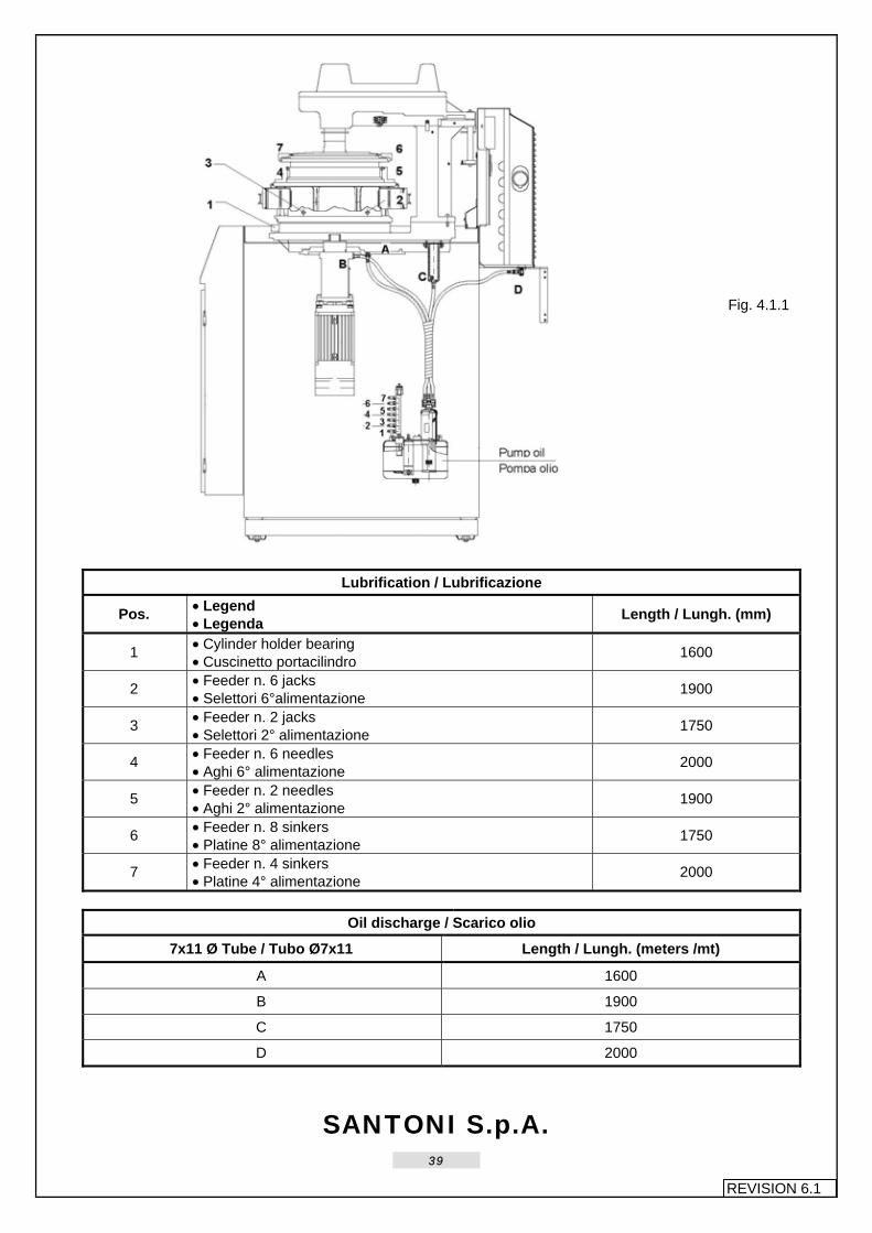
Lubrication with dropsa system See Fig. 4.1.1 Lubrication is carried out by means of a first delivery of oil to a series of junction points on the tank, out of which a number of plastic tubes come out and provide for the distribution of the lubricant to the various machine parts.
4 LUBRIFICAZIONE E COMANDI PNEUMATICI
4.1 Lubrificazione 4.1.1 Lubrificazione autonoma
La macchina è corredata di un oliatore automatico a recupero e riciclaggio continuo dell’olio lubrificante, con arresto della macchina nei seguenti casi: A Superamento del livello minimo. B Eventuale diminuzione di pressione
nel circuito di lubrificazione. Tale oliatore funziona ad aria compressa ed è posto all’interno del basamento sul lato destro. Il suo scopo principale è di assicurare un continuo apporto di lubrificazione nei punti più delicati ed importanti della macchina.
Lubrificazione con dispositivo dropsa Vedi Fig. 4.1.1 La lubrificazione avviene tramite una prima mandata di olio ad una serie di raccordi posti sul serbatoio stesso, dai quali partono dei tubetti di plastica che provvedono a distribuire il lubrificante nei vari punti della macchina.
SANTONI S.p.A.
39
REVISION 6.1
Fig. 4.1.1
Lubrification / Lubrificazione
Pos. • Legend • Legenda Length / Lungh. (mm)
1 • Cylinder holder bearing • Cuscinetto portacilindro 1600
2 • Feeder n. 6 jacks • Selettori 6°alimentazione 1900
3 • Feeder n. 2 jacks • Selettori 2° alimentazione 1750
4 • Feeder n. 6 needles • Aghi 6° alimentazione 2000
5 • Feeder n. 2 needles • Aghi 2° alimentazione 1900
6 • Feeder n. 8 sinkers • Platine 8° alimentazione 1750
7 • Feeder n. 4 sinkers • Platine 4° alimentazione 2000
Oil discharge / Scarico olio
7x11 Ø Tube / Tubo Ø7x11 Length / Lungh. (meters /mt)
A 1600
B 1900
C 1750
D 2000

SANTONI S.p.A.
40
REVISION 6.1
4.1.2 Maintenance
As regards the maintenance of the automatic oiler, the following operations are required: 1. Check of oil level and eventual topping. 2. Cleaning of pre-filter at the entry of the
recovered lubricant: this operation is to be carried out on a regular basis.
After 3 months of functioning replace the paper filter and then replace it every 6 months. Cleaning of lubricant tank with naphtha: this operation is to be carried out once a year and after the first 3 months of functioning.
4.1.2 Manutenzione Per quanto riguarda la manutenzione dell’oliatore automatico, è sufficiente eseguire: 1 Controllo ed eventuale rabbocco dell’olio
lubrificante . 2 Pulitura del prefiltro posto all’entrata
dell’olio lubrificante recuperato: operazione da eseguire periodicamente.
Sostituire il filtro di carta dopo i primi 3 mesi di funzionamento e, successivamente sostituirlo ogni 6 mesi. Lavaggio con nafta del contenitore lubrificante, operazione da eseguire una volta all’anno e dopo i primi 3 mesi di funzionamento.
WARNING! After cleaning the tank, or should the lubricant need to be completely changed, proceed as follows: 1. Move the key to PROG position and
press the key [SPACE] .
2. In the MAIN MENU page press the key [E] (Execute autotest)
3. In the AUTOTEST MODE page
press the key [U] (oUtputs autotest) 4. In the OUTPUT AUTOTEST page
press the key [C] (Chain autotest) 5. In the CHAIN AUTOTEST page
press the key [F] (dial Functions) 6. In the CHAIN AUTO-TEST page to
find the function “oiler command”, and press the key associate function [F..] continuously until the lubrificant tubes are completely filled (should air bubbles form, purge them).
ATTENZIONE! Dopo il lavaggio del contenitore, o se si dovesse sostituire completamente l’olio del lubrificatore, si proceda nel seguente modo: 1. Portarsi con la chiave in posizione
PROG - nella finestra principale premere il tasto [SPACE] .
2. Nella pagina MENU GESTIONE
premere il tasto di scelta rapida [E] (auto tEst).
3. Nella pagina MENU AUTOTEST
premere il tasto di scelta rapida [U] (autotest Uscite)
4. Nella pagina AUTOTEST USCITE
premere il tasto di scelta rapida [C] (autotest Catena)
5. Nella pagina MENU TEST CATENA
premere il tasto di scelta rapida [F] (Funzione platò)
6. Nella pagina AUTO-TEST CATENA
cercare la funzione “Comando oliatore”, e premere in continuzaione il tasto funzione associato [F..], fino al riempimento completo delle cannette dell’olio (in caso di bolle nelle cannette provvedere allo spurgo).

SANTONI S.p.A.
41
REVISION 6.1
4.1.3 Lubricant
It is advisable to use Fuchs – Trax 1 4BL (visc.32). If this lubricant is not available, we recommend using an oil with the same characteristics. WARNING! The SANTONI company is not responsible for eventual damage to the machine caused by improper use of oils with detergent additives or oils which do not have the same characteristics of the aforementioned brand. The proper lubrication of the machine requires that the first lubrication be abundant for the first month of functioning. After this period, adapt lubrication (number of pump deliveries) to the garment being produced.
4.1.4 Manual lubrication Check the state of lubrication of the dial jacks every two months, and apply ISOFLEX NCA 15 (Kluber) grease if necessary. Once a year pump some grease into the grease nipple provided on the dial (TAMLITH Grease 2).
4.1.3 Lubrificante Si consiglia di usare il: Fuchs – Trax 1 4 BL (visc.32). Nel caso in cui sia impossibile reperire il sopraindicato lubrificante si consiglia di usare un olio che abbia caratteristiche uguali. ATTENZIONE! La Ditta SANTONI non risponde ad eventuali danni arrecati alla macchina, causati da un uso improprio di olii con aggiunta di additivi detergenti, o olii che non abbiano le stesse caratteristiche della marca sopra citata. Al fine di una buona lubrificazione, si consiglia di fare una lubrificazione abbondante per il primo mese di lavoro, quindi, dopo tale periodo adeguare la lubrificazione (n° mandate pompa) all’articolo in produzione.
4.1.4 Lubrificazione manuale Controllare ogni due mesi lo stato di lubrificazione degli uncini e se è il caso mettere un pò di grasso ISOFLEX NCA 15 (Kluber). Ogni anno pompare un pò di grasso nell’apposito ingrassatore posto sul platò (Grasso TAMLITH Grease 2).

SANTONI S.p.A.
42
REVISION 6.1
4.2 Pneumatic control system
The operation of all the current machine devices is controlled by a pneumatic system with solenoid valves. To ensure proper operation of the machine and to prevent uneven wear of the gaskets, use dried compressed air having the following characteristics: Temperature as it comes from the dryer 18/21°C Humidity 0° When replacing gaskets on moving parts (sliders, yarn fingers, etc.), grease the gasket with: Recommended grease: TECNOLUBE SEAL – FLUOROCARBON GEL 885 otherwise or use VISCOL – SIGNAL PASTA-TS.
4.2 Sistema comandi pneumatici Il funzionamento di tutti i meccanismi delle macchine attuali sono a sistema pneumatico tramite elettrovalvole. Per la buona efficienza della macchina e per evitare l’usura anomala delle guarnizioni, ricordiamo di utilizzare aria compressa essiccata con i seguenti parametri: Temperatura uscita essiccatore 18/21°C Umidità 0° In caso di sostituzione di una guarnizione sui meccanismi in movimento (corsoi, guidafili etc.) ingrassare la guarnizione con: Grasso da noi consigliato: TECNOLUBE SEAL – FLUOROCARBON GEL 885 o in alternativa il VISCOL – SIGNAL PASTA-TS.
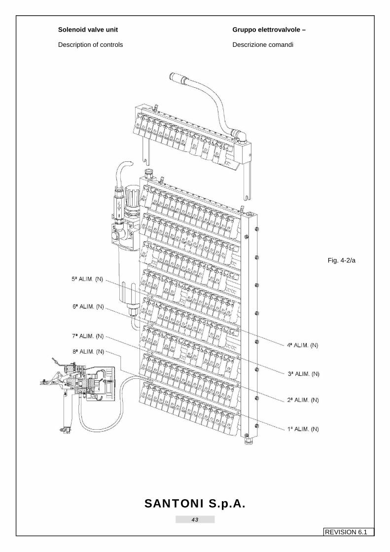
SANTONI S.p.A.
43
REVISION 6.1
Solenoid valve unit Description of controls
Gruppo elettrovalvole – Descrizione comandi
Fig. 4-2/a

SANTONI S.p.A.
44
REVISION 6.1
Legend EV101 Intermediate dial cam B 8th feeder EV102 Intermediate dial cam A 8th feeder EV103 Intermediate dial cam B 7th feeder EV104 Intermediate dial cam A 7th feeder EV105 Intermediate dial cam B 6th feeder EV106 Intermediate dial cam A 6th feeder EV107 Intermediate dial cam B 5th feeder EV108 Intermediate dial cam A 5th feeder EV109 Intermediate dial cam B 1st feeder EV110 Intermediate dial cam A 1st feeder EV111 Intermediate dial cam B 2nd feeder EV112 Intermediate dial cam A 2nd feeder EV113 Intermediate dial cam B 3rd feeder EV114 Intermediate dial cam A 3rd feeder EV115 Intermediate dial cam B 4th feeder EV116 Intermediate dial cam A 4th feeder EV201 Needle lowering cam colour 1 B 8th feeder EV202 Needle lowering cam colour 1 A 8th feeder EV203 Needle lowering cam colour 1 B 7th feeder EV204 Needle lowering cam colour 1 A 7th feeder EV205 Needle lowering cam colour 1 B 6th feeder EV206 Needle lowering cam colour 1 A 6th feeder EV207 Needle lowering cam colour 1 B 5th feeder EV208 Needle lowering cam colour 1 A 5th feeder EV209 Needle lowering cam colour 1 B 1st feeder EV210 Needle lowering cam colour 1 A 1st feeder EV211 Needle lowering cam colour 1 B 2nd feeder EV212 Needle lowering cam colour 1 A 2nd feeder EV213 Needle lowering cam colour 1 B 3rd feeder EV214 Needle lowering cam colour 1 A 3rd feeder EV215 Needle lowering cam colour 1 B 4th feeder EV216 Needle lowering cam colour 1 A 4th feeder EV302 Tuck stitch B 5th feeder EV303 Cleared stitch B 5th feeder EV305 Tuck stitch 5th feeder EV306 Cleared stitch 5th feeder EV310 Cleared stitch B 4th feeder EV312 Tuck stitch B 4th feeder EV313 Tuck stitch 4th feeder EV314 Cleared stitch 4th feeder EV316 Recovery of runner slack EV402 Cleared stitch B 8th feeder EV404 Tuck stitch B 6th feeder EV405 Tuck stitch 6th feeder EV406 Cleared stitch 6th feeder EV407 Cymbal opener control EV410 Tuck stitch B 3rd feeder EV411 Cleared stitch B 3rd feeder EV413 Tuck stitch 3rd feeder EV414 Cleared stitch 3rd feeder
Legenda: EV101 Camma selettori intermedi B 8ª alim. EV102 Camma selettori intermedi A 8ª alim. EV103 Camma selettori intermedi B 7ª alim. EV104 Camma selettori intermedi A 7ª alim. EV105 Camma selettori intermedi B 6ª alim. EV106 Camma selettori intermedi A 6ª alim. EV107 Camma selettori intermedi B 5ª alim. EV108 Camma selettori intermedi A 5ª alim. EV109 Camma selettori intermedi B 1ª alim. EV110 Camma selettori intermedi A 1ª alim. EV111 Camma selettori intermedi B 2ª alim. EV112 Camma selettori intermedi A 2ª alim. EV113 Camma selettori intermedi B 3ª alim. EV114 Camma selettori intermedi A 3ª alim. EV115 Camma selettori intermedi B 4ª alim. EV116 Camma selettori intermedi A 4ª alim. EV201 Camma abbassa aghi colore 1 B 8ª alim. EV202 Camma abbassa aghi colore 1 A 8ª alim. EV203 Camma abbassa aghi colore 1 B 7ª alim. EV204 Camma abbassa aghi colore 1 A 7ª alim. EV205 Camma abbassa aghi colore 1 B 6ª alim. EV206 Camma abbassa aghi colore 1 A 6ª alim. EV207 Camma abbassa aghi colore 1 B 5ª alim. EV208 Camma abbassa aghi colore 1 A 5ª alim. EV209 Camma abbassa aghi colore 1 B 1ª alim. EV210 Camma abbassa aghi colore 1 A 1ª alim. EV211 Camma abbassa aghi colore 1 B 2ª alim. EV212 Camma abbassa aghi colore 1 A 2ª alim. EV213 Camma abbassa aghi colore 1 B 3ª alim. EV214 Camma abbassa aghi colore 1 A 3ª alim. EV215 Camma abbassa aghi colore 1 B 4ª alim. EV216 Camma abbassa aghi colore 1 A 4ª alim. EV302 Trattenuto B 5ª alimentazione EV303 Scaricato B 5ª alimentazione EV305 Trattenuto 5ª alimentazione EV306 Scaricato 5ª alimentazione EV310 Scaricato B 4ª alimentazione EV312 Trattenuto B 4ª alimentazione EV313 Trattenuto 4ª alimentazione EV314 Scaricato 4ª alimentazione EV316 Recupero gioco slitte EV402 Scaricato B 8ª alimentazione EV404 Trattenuto B 6ª alimentazione EV405 Trattenuto 6ª alimentazione EV406 Scaricato 6ª alimentazione EV407 Comando apripiattelli EV410 Trattenuto B 3ª alimentazione EV411 Scaricato B 3ª alimentazione EV413 Trattenuto 3ª alimentazione EV414 Scaricato 3ª alimentazione

SANTONI S.p.A.
45
REVISION 6.1
EV502 Tuck stitch B 7th feeder EV503 Cleared stitch B 7th feeder EV505 Tuck stitch 7th feeder EV506 Cleared stitch 7th feeder EV510 Cleared stitch B 6th feeder EV511 Cleared stitch B 2nd feeder EV512 Tuck stitch B 2 nd feeder EV513 Tuck stitch 2nd feeder EV514 Cleared stitch 2nd feeder EV604 Tuck stitch B 8th feeder EV605 Tuck stitch 8th feeder EV606 Cleared stitch 8th feeder EV607 Oiler control EV608 Panty ejection command EV610 Tuck stitch B 1st feeder EV611 Cleared stitch B 1st feeder EV613 Tuck stitch 1st feeder EV614 Cleared stitch 1st feeder EV701 Knit blow press EV702 Spandex cutter 6th feeder EV703 Remove yarn cutter 6th feeder EV704 Cleaning air blowers 1-2-5-6 EV705 Cleaning air blowers 3-4-7-8 EV706 Remove yarn cutter 8th feeder EV707 Dial jack air blower EV711 Spandex cutter 2nd feeder EV712 Remove yarn cutter 4th feeder EV713 Lower dial EV714 Raise dial EV715 Remove yarn cutter 4th feeder EV801 Stop needles control EV803 Lower dial jack EV804 Partial jack re-entry EV805 Total jack 2 re-entry EV806 High butt jack exit EV807 Total jack 3 exit EV808 High butt jack re-entry EV809 Spandex cutter 5th feeder EV810 Spandex cutter 6th feeder EV811 Spandex cutter 7th feeder EV812 Spandex cutter 8th feeder EV813 Spandex cutter 1st feeder EV814 Spandex cutter 2nd feeder EV815 Spandex cutter 3rd feeder EV816 Spandex cutter 4th feeder
EV502 Trattenuto B 7ª alimentazione EV503 Scaricato B 7ª alimentazione EV505 Trattenuto 7ª alimentazione EV506 Scaricato 7ª alimentazione EV510 Scaricato B 6ª alimentazione EV511 Scaricato B 2ª alimentazione EV512 Trattenuto B 2ª alimentazione EV513 Trattenuto 2ª alimentazione EV514 Scaricato 2ª alimentazione EV604 Trattenuto B 8ª alimentazione EV605 Trattenuto 8ª alimentazione EV606 Scaricato 8ª alimentazione EV607 Comando oliatore EV608 Comando espulsore mutanda EV610 Trattenuto B 1ª alimentazione EV611 Scaricato B 1ª alimentazione EV613 Trattenuto 1ª alimentazione EV614 Scaricato 1ª alimentazione EV701 Soffio pressa maglia EV702 Pinza gomma 6ª alimentazione EV703 Elimina coltellino 6ª alimentazione EV704 Soffio pulizia bocchette 1-2-5-6 EV705 Soffio pulizia bocchette 3-4-7-8 EV706 Elimina coltellino 8ª alimentazione EV707 Soffio uncini EV711 Pinza gomma 2ª alimentazione EV712 Elimina coltellino 2ª alimentazione EV713 Abbassa platò EV714 Alza platò EV715 Elimina coltellino 4ª alimentazione EV801 Comando stop aghi EV803 Abbassa platorello EV804 Rientro parziale uncini EV805 Rientro totale uncini 2 EV806 Uscita uncini tallone alto EV807 Uscita totale uncini 3 EV808 Rientro uncini tallone alto EV809 Pinza elastico 5ª alimentazione EV810 Pinza elastico 6ª alimentazione EV811 Pinza elastico 7ª alimentazione EV812 Pinza elastico 8ª alimentazione EV813 Pinza elastico 1ª alimentazione EV814 Pinza elastico 2ª alimentazione EV815 Pinza elastico 3ª alimentazione EV816 Pinza elastico 4ª alimentazione

SANTONI S.p.A.
46
REVISION 6.1
NOTE OPTIONAL EV301 terry sinker cam 5th feeder EV309 terry sinker cam 4th feeder EV401 terry sinker cam 6th feeder EV408 latch opener 5th feeder EV409 terry sinker cam 3rd feeder EV501 terry sinker cam 7th feeder EV509 terry sinker cam 2nd feeder EV515 air blowers 3-4-7-8 feeders EV516 air blowers 1-2-5-6 feeders EV601 terry sinker cam 8th feeder EV609 terry sinker cam 1st feeder EV708 Spandex cutter 8th feeder EV709 sinker cap control EV710 Spandex cutter 4th feeder EV1001 solenoid valve client 1 EV1002 solenoid valve client 2 EV1003 solenoid valve client 3 EV1004 solenoid valve client 4 EV1005 solenoid valve client 5 EV1006 solenoid valve client 6 EV1007 solenoid valve client 7 EV1008 solenoid valve client 8 EV1009 spandex cutter 1th feeder EV1011 spandex cutter 3th feeder EV1013 spandex cutter 5th feeder EV1015 spandex cutter 7th feeder Feeder legend 1st feeder = yarn finger feed unit, 1st feeder 2nd feeder = yarn finger feed unit, 2nd feeder 3rd feeder = yarn finger feed unit, 3rd feeder 4th feeder = yarn finger feed unit, 4th feeder 5th feeder = yarn finger feed unit, 5th feeder 6th feeder = yarn finger feed unit, 6th feeder 7th feeder = yarn finger feed unit, 7th feeder 8th feeder = yarn finger feed unit, 8th feeder • 5-way bistable valve feeder used to raise/lower the horizontal unit Note: the tube to be used for all connections is diam. 3.17
NOTA OPTIONAL EV301 cam platine spugna 5ª alim. EV309 cam platine spugna 4ª alim. EV401 cam platine spugna 6ª alim. EV408 apri piattelli 5ª alim. EV409 cam platine spugna 3ª alim. EV501 cam platine spugna 7ª alim. EV509 cam platine spugna 2ª alim. EV515 asp. bocchette 3-4-7-8 alim. EV516 aspiraz. Bocchette 1-2-5-6 al. EV601 cam platine spugna 8ª alim. EV609 cam platine spugna 1ª alim. EV708 pinza gomma 8ª alim. EV709 comando coperchio platine EV710 pinza gomma 4ª alim. EV1001 elettrovalvola clienti 1 EV1002 elettrovalvola clienti 2 EV1003 elettrovalvola clienti 3 EV1004 elettrovalvola clienti 4 EV1005 elettrovalvola clienti 5 EV1006 elettrovalvola clienti 6 EV1007 elettrovalvola clienti 7 EV1008 elettrovalvola clienti 8 EV1009 pinza gomma 1ª alim. EV1011 pinza gomma 3ª alim. EV1013 pinza gomma 5ª alim. EV1015 pinza gomma 7ª alim. Legenda alimentazioni 1° alim.= alim. gruppo guidafili 1ª alim. 2° alim.= alim. gruppo guidafili 2ª alim. 3° alim.= alim. gruppo guidafili 3ª alim. 4° alim.= alim. gruppo guidafili 4ª alim. 5° alim.= alim. gruppo guidafili 5ª alim. 6° alim.= alim. gruppo guidafili 6ª alim. 7° alim.= alim. gruppo guidafili 7ª alim. 8° alim.= alim. gruppo guidafili 8ª alim. • = alimentazione valvola a 5 vie bistabile per cilindro alza/abbassa gruppo orizzontale Nota:Il tubetto da usare per tutte le connessioni è di Ø3.17

SANTONI S.p.A.
47
REVISION 6.1
“Start” general pneumatic commands For index see the next page.
Comandi pneumatici generali “di partenza” Per l’indice vedi pagina successiva
Fig. 4-2/b

SANTONI S.p.A.
48
REVISION 6.1
Legend A Ø6x1050 Tube + Y-shaped fitting B Ø6x1200 Tube + Y-shaped fitting C Ø6x1900 Tube D Ø6x700 Tube E Ø6x150 Tube M 8 tubes diam. 3.17 for stitch cam units
pneumatic spring Legend 1 Piloted by SOLENOID VALVE 713 2 Horizontal welt, low use by 1 3 Horizontal welt, high use by 4 4 Piloted by SOLENOID VALVE714 Tubes 1 Ø 3.17x700 2 Ø 3.17x700 3 Ø 3.17x500 4 Ø 3.17x700 5 Condensation discharge Ø 6x250
Legenda A Tubo Ø6x1050 + raccordo Y B Tubo Ø6x1200 + raccordo Y C Tubo Ø6x1900 D Tubo Ø6x700 E Tubo Ø6x150 M n° 8 tubi Ø 3.17 per molla pneumatica
gruppi camme maglia Legenda 1 Pilotaggio da EV713 2 Orizz. bordo basso utilizzo da 1 3 Orizz. bordo alto utilizzo da 4 4 Pilotaggio da EV714 Tubetti 1 Ø3.17x700 2 Ø3.17x700 3 Ø3.17x500 4 Ø3.17x700 5 Scarico condensa Ø6x250

SANTONI S.p.A.
49
REVISION 6.1
Feeding to and from the yarn finger unit.
A: latch opener – latch stop – N.B. See diagram electric for yarn feed serial solenoid valve connections and feeds.
Alimentazione a gruppo guidafili e dal gruppo guidafili. A: apriago – stop linguette – N.B. Connessioni e alimentazioni E.V. seriali/guidafili vedi schemi elettrici .
Fig. 4-2/d N.B. The same connections are to be made for all feeds. See Fig. 4-2/a pag. 42 for reference N.
N.B. le connessioni si ripetono allo stesso modo su tutte le alimentazioni. Per riferimenti N vedi Fig. 4-2/a pag.42

SANTONI S.p.A.
50
REVISION 6.1
Upper plate pneumatic commands N.B. See Fig. 4-2/b for reference M.
Piatto superiore comandi pneumatici N.B. Per riferimenti M vedi Fig. 4-2/b
Fig. 4-2/f
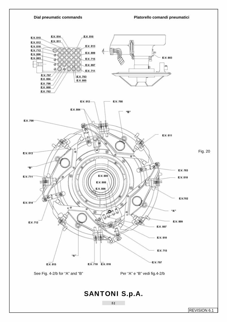
SANTONI S.p.A.
51
REVISION 6.1
Dial pneumatic commands Platorello comandi pneumatici
Fig. 20
See Fig. 4-2/b for “A” and “B” Per “A” e “B” vedi fig.4-2/b

SANTONI S.p.A.
52
REVISION 6.1
Mobile sinker cap: terry fabric pneumatic commands
Coperchio platine mobile: spugna comandi pneumatici
Fig. 21

SANTONI S.p.A.
53
REVISION 6.1
Fixed sinker cap: plain fabric pneumatic commands
Coperchio platine fisso: maglia liscia comandi pneumatici
Fig. 22

SANTONI S.p.A.
54
REVISION 6.1
Sensor holder ring with plate opener piston pneumatic commands
Anello porta sensori con pistone apripiattelli comandi pneumatici
Fig.23
Ø 3.17 Pipe / Tubo Ø 3.17 Pipe N° / N° Tubo Length / Lungh. (mm)
A 407 1300
B 180
C 250
D 408 2000

SANTONI S.p.A.
55
REVISION 6.1
5 ADJUSTMENTS
5.1 Machine phases 5.1.1 Mechanical “0” machine phase
See Fig. 5-1/a Should the machine phase need to be verified, proceed as follows: 1. Activate end cycle by pressing the
button [F3] and chain stop with [F1] 2. Move the selector key on PROG
(programming”) and press [SPACE]. 3. Press key [Z]; enter the secret code
[* * * *] and press [RETURN] to confirm.
4. In the page ENCODER ZERO to
choose the option [M] manual procedure.
5. Press key (crank electronic), until the machine displays degree/needle starts counting – at this point to move the phase needle near the corresponding mark on the cylinder (that coincide with the cylinder featherkey - check the cylinder position in Fig. 29 and Fig.30 needle arrangement) so that it coincides with the notch located on the counterring between the 8th and 1th feed.
6. Once caught up the position to press
key [RETURN]. = memorize.
5 REGISTRAZIONI
5.1 Fasi macchina 5.1.1 Fase “0” macchina meccanico
Vedi Fig. 5-1/a Qualora vi sia bisogno di verificare la fase della macchina procedere nel seguente modo: 1 Portarsi a fine ciclo, premendo il
pulsante [F3] e in fermo catena con [F1].
2 Portare la chiave selettore in
posizione PROG. (programmazione) e premere [SPACE].
3 Premere il tasto [Z] e digitare il
codice segreto [* * * *] – confermare poi con il tasto [RETURN].
4 Nella pagina ZERO ENCODER
scegliere l’opzione [M] (procedura manuale).
5 Premere ripetutamente il tasto (manovella elettronica), fino a quando sul display inizia il conteggio gradi/aghi – a questo punto portare l’ago di fase, che si trova in corrispondenza di un segno posto sul cilindro (che collima con il centro chiavetta del cilindro - vedi posizione di questo alla Fig.29 e 30 disposizione aghi) a coincidere con una tacca posta sul controanello tra la 8° e 1° alimentazione.
6 Una volta raggiunta la posizione
premere il tasto [RETURN].= acquisisce.

SANTONI S.p.A.
56
REVISION 6.1
Fig. 5-1/a
Fig. 5-1/b

SANTONI S.p.A.
57
REVISION 6.1
5.1.2 Manual calibration “0” machine encoder
phase saved during “SET UP”. See Fig. 5-1/a Fig. 5-1/b and Fig. 5-1-1/a. Should it be necessary to replace the G encoder or the E encoder flexible coupling, the machine phasing needs to be reset. 1. Block the G flexible coupling both on
the encoder pin and on the dial pin with the A and C dowels. Block screws B as well.
2. Activate the end cycle with the mode
key selector in PROG. (programming) and press [SPACE].
3. Press [Z] and insert the secret code [*
* * *] - press [RETURN] key to confirm. 4. In the ZERO ENCODER page to
choose the option [M] (manual procedure).
5. Press repeatedly the key (electronic handle) until the machine displays degree/needle starts counting – at this point to resume the mechanical condition of Fig. 5-1/b; selector 1 needs to be located in correspondence of the phase plate tooth.
6. Press [RETURN] to load the “0”
degree position: the “Position loaded” message will appear in the Warning field.
7. Press [ESC] and then [S] to save the
previously loaded position; wait for the message to appear before shutting the machine off.
5.1.2 Taratura manuale fase encoder “0” macchina memorizzato nel “SET UP”. Vedi Fig. 5-1/a Fig. 5-1/b e Fig. 5-1-1/a. Qualora vi sia bisogno di cambiare il giunto elastico dell’encoder G o l’encoder E è necessario rifare la fase della macchina. 1. Bloccare il giunto elastico G sia
sul perno dell’encoder sia sul perno del platorello con i grani A e C. Bloccare inoltre le viti B.
2. Portarsi a fine ciclo con chiave
selettore in posizione PROG. (programmazione) e premere il tasto [SPACE]
3. Premere il tasto [Z] e digitare il
codice segreto [* * * *] - premere [RETURN] per confermare
4. Nella pagina ZERO ENCODER
scegliere l’opzione [M] (procedura manuale).
5. Premere ripetutamente il tasto
(manovella elettronica), fino a quando sul display inizia il conteggio gradi/aghi – a questo punto ripristinare la condizione meccanica di Fig. 5-1/b, selettore 1 in corrispondenza della punta del dente della piatrina di fase.
6. Premere [RETURN] per
l’acquisizione della posizione del grado “0”: nella zona Warning uscirà il messaggio “Posizione acquisita”.
7. Premere [ESC] e poi [S] per la
memorizzazione della precedente acquisizione; attendere il messaggio prima di procedere allo spegnimento della macchina.

SANTONI S.p.A.
58
REVISION 6.1
N.B. After having re-started the machine, check that the selection levers of the actuators move from the bottom to the top e vice versa, right after the passage of the tooth of the selector in the vertical position where they must operate. If this does not occur, one must establish the quantity of needles that are to be anticipated or delay the abovementioned movement and then, repeating the operations cited at the beginning, re-acquire the position of Zero Encoder, adding or subtracting the needles defined for the modification. At this stage check that the plate coincides with the marked phase selector when degree “0” or needle “0” is shown on the display, otherwise move it.
N.B. Nel riaccendere la macchina si dovrà verificare che le levette selezionatrici degli attuatori si muovano dal basso verso l’alto e viceversa, subito dopo il passaggio del dentino del selettore, nella posizione verticale dove devono operare. Se questo non si dovesse verificare, si dovrà stabilire la quantità di aghi che si vuole anticipare o ritardare il suddetto movimento e quindi, ripetendo le operazioni citate all’inizio, riacquisire la posizione di Zero Encoder, aggiungendo o sottraendo gli aghi definiti per la modifica. Successivamente verificare che la piastrina sia in corrispondenza del selettore di fase, quando sul display appare grado “0” e ago “0”, altrimenti spostarla.
Fig. 5.1.1/a
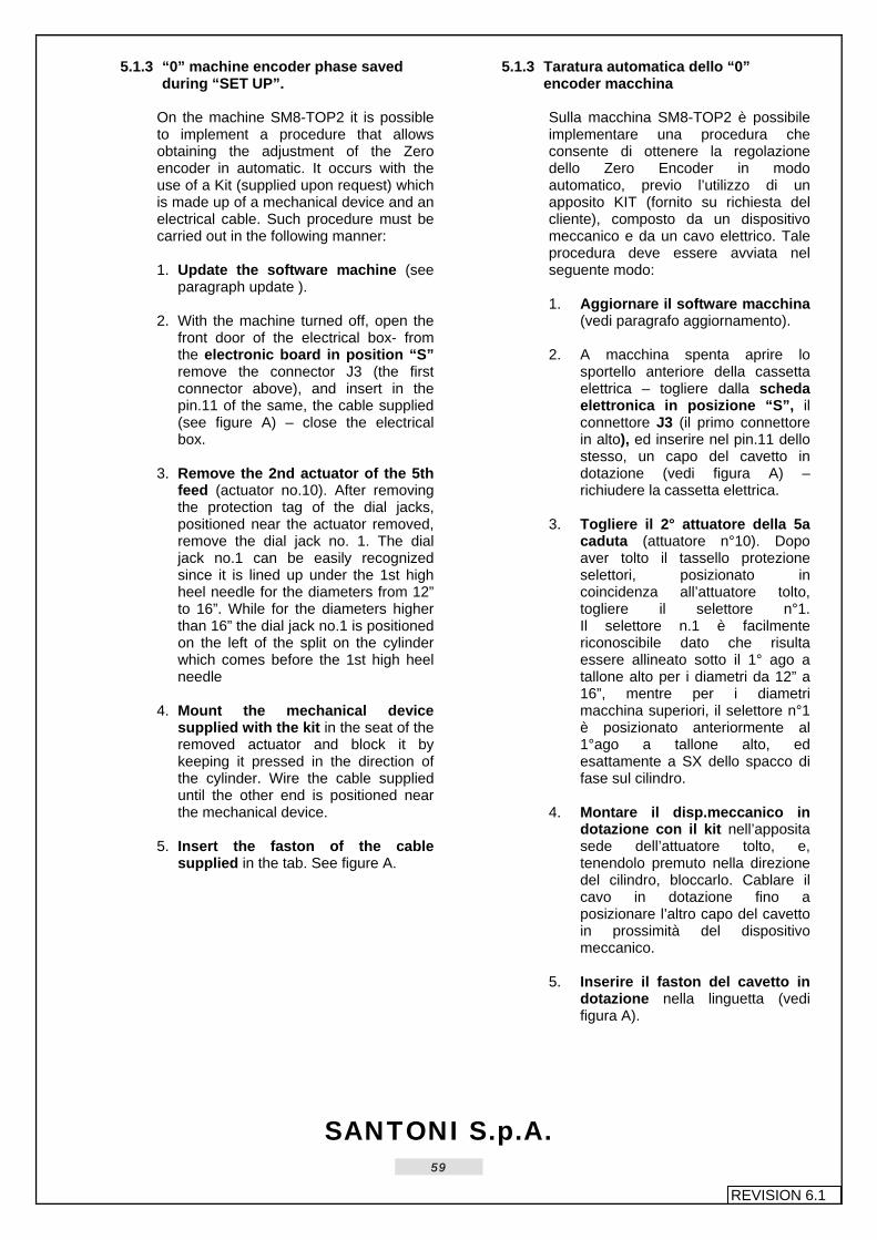
SANTONI S.p.A.
59
REVISION 6.1
5.1.3 “0” machine encoder phase saved
during “SET UP”. On the machine SM8-TOP2 it is possible to implement a procedure that allows obtaining the adjustment of the Zero encoder in automatic. It occurs with the use of a Kit (supplied upon request) which is made up of a mechanical device and an electrical cable. Such procedure must be carried out in the following manner: 1. Update the software machine (see
paragraph update ). 2. With the machine turned off, open the
front door of the electrical box- from the electronic board in position “S” remove the connector J3 (the first connector above), and insert in the pin.11 of the same, the cable supplied (see figure A) – close the electrical box.
3. Remove the 2nd actuator of the 5th
feed (actuator no.10). After removing the protection tag of the dial jacks, positioned near the actuator removed, remove the dial jack no. 1. The dial jack no.1 can be easily recognized since it is lined up under the 1st high heel needle for the diameters from 12” to 16”. While for the diameters higher than 16” the dial jack no.1 is positioned on the left of the split on the cylinder which comes before the 1st high heel needle
4. Mount the mechanical device
supplied with the kit in the seat of the removed actuator and block it by keeping it pressed in the direction of the cylinder. Wire the cable supplied until the other end is positioned near the mechanical device.
5. Insert the faston of the cable
supplied in the tab. See figure A.
5.1.3 Taratura automatica dello “0” encoder macchina Sulla macchina SM8-TOP2 è possibile implementare una procedura che consente di ottenere la regolazione dello Zero Encoder in modo automatico, previo l’utilizzo di un apposito KIT (fornito su richiesta del cliente), composto da un dispositivo meccanico e da un cavo elettrico. Tale procedura deve essere avviata nel seguente modo: 1. Aggiornare il software macchina
(vedi paragrafo aggiornamento). 2. A macchina spenta aprire lo
sportello anteriore della cassetta elettrica – togliere dalla scheda elettronica in posizione “S”, il connettore J3 (il primo connettore in alto), ed inserire nel pin.11 dello stesso, un capo del cavetto in dotazione (vedi figura A) – richiudere la cassetta elettrica.
3. Togliere il 2° attuatore della 5a
caduta (attuatore n°10). Dopo aver tolto il tassello protezione selettori, posizionato in coincidenza all’attuatore tolto, togliere il selettore n°1. Il selettore n.1 è facilmente riconoscibile dato che risulta essere allineato sotto il 1° ago a tallone alto per i diametri da 12” a 16”, mentre per i diametri macchina superiori, il selettore n°1 è posizionato anteriormente al 1°ago a tallone alto, ed esattamente a SX dello spacco di fase sul cilindro.
4. Montare il disp.meccanico in
dotazione con il kit nell’apposita sede dell’attuatore tolto, e, tenendolo premuto nella direzione del cilindro, bloccarlo. Cablare il cavo in dotazione fino a posizionare l’altro capo del cavetto in prossimità del dispositivo meccanico.
5. Inserire il faston del cavetto in
dotazione nella linguetta (vedi figura A).

SANTONI S.p.A.
60
REVISION 6.1
Fig.A
ATTENZIONE • Before carrying out the machine
rotation check that the press mounted on the mechanical device does not interfere with dial jacks on the Cylinder Low Background.
• It this should happen, act on the
adjustment grain of the mechanical device, after loosening its fixing screws.
6. Once dial jack no.1 is removed and
the device has been mounted correctly, start the automatic learning procedure.
a). Activate a program. b). Turn the key in programming and
press [SPACE] and [Z] c). Insert secret code [* * * *] and
press [RETURN].
ATTENZIONE • Prima di effettuare la rotazione
della m/c verificare che la pressa, montata sul disp.meccanico, non porti in interferenza i selettori sul Basso Fondo Cilindro (BFC).
• Se ciò si dovesse verificare, si può
agire sul grano di registro del disp.meccanico, previo allentamento delle viti di fissaggio dello stesso.
6. Tolto il selettore n° 1 ed effettuato
correttamente il montaggio del dispositivo avviare la procedura automatica dell’autoapprendimento.
a) Rendere Attivo un programma. b) Girare la chiave in
programmazione e premere i tasti [SPACE] e [Z].
c) Digitare il codice segreto [* * * *] e premere [RETURN].

SANTONI S.p.A.
61
REVISION 6.1
d). Press button [A] and then the
START button. e). When the procedure is finished the
machine will stop requesting to be turned off.
The automatic procedure of the Zero Encoder is finished. Now you must restore the initial setting. 7. With the machine off, to take off the
faston; to take off the device mechanical; insert dial jack no.1; remount the protection tag and remount the actuator previously removed.
8. As in figure 5-1/b redefine the position
of the plate in order for it to be aligned with the dial jack phase plate tooth.
At this point the machine is ready to start production.
d) Premere il tasto [A] e successivamente il pulsante di marcia START.
e) Quando la procedura sarà terminata la m/c si arresterà con la richiesta di essere spenta.
La procedura automatica dello Zero Encoder è terminata; a questo punto si dovrà ripristinare la condizione iniziale. 7. A macchina spenta sconnettere il
faston dalla linguetta; togliere il dispositivo meccanico (precedentemente montato); reinserire il selettore n°1; rimontare il tassello protezione selettori e l’attuatore precedentemente smontato.
8. Come da Fig.5-1/b ridefinire la
posizione della piastrina affinché sia allineata con il selettore di fase (con tacca sul piede).
A questo punto la mc è pronta per essere avviata alla produzione.

SANTONI S.p.A.
62
REVISION 6.1
5.1.4 Machine transmission phase
See Fig. 27 and Fig. 28 The phase marks are made during machine manufacturing and they are signalled with either a notch or a “0” mark, which are emphasised with white paint during assembly. The coupled units are the following: 1. Cylinder holder – Gear on
cylinder holder – Pulley on cylinder holder. These parts are timed automatically since they are equipped with a key or pin. The unit assembled this way must have the slot located on the cylinder holder positioned at 180° compared to the machine front. This situation is provided for by the conditions of paragraph 5.1.1.
2. Edge vertical shaft – Lower
flange with pulley – Upper flange with pulley. The “0” on the lower flange and the “0” on the upper flange must be timed with the “0” stamped on the bottom of the vertical shaft and with the phase mark located on the upper tooth of the shaft itself
3. The phase mark located on the
pulley box mounted on the dial unit must be turned until it coincides with the phase mark found on the welt horizontal support.
N.B. When the transmission is positioned as described above, mount the corresponding belts.
5.1.4 Fase trasmissione macchina Vedi Fig. 27 e Fig. 28 I segni di fase vengono eseguiti durante la costruzione della macchina e sono contrassegnati con una ceccatura o con un segno “0”, che durante l’assemblatura vengono evidenziati con della vernice bianca. I gruppi in accoppiamento sono i seguenti: 1. Portacilindro - Ingranaggio su porta-
cilindro – Puleggia su portacilindro. Questi particolari si fasano automaticamente essendo dotati di chiavetta o spina. Il gruppo cosi montato deve avere lo spacco esistente sul portacilindro a 180° rispetto al “davanti” M/C; condizione garantita nelle condizioni del paragrafo 5.1.1.
2. Albero verticale bordo – Flangia
inferiore con montata la sua puleggia – Flangia superiore con montata la sua puleggia. Lo “0” sulla flangia inferiore e lo “0” sulla flangia superiore devono essere montati in fase rispettivamente con lo “0” stampigliato sul fondo albero verticale e con il segno di fase esistente sul dente superiore dell’albero stesso.
3. Il “segno di fase” esistente sul vano
della puleggia montata sul gruppo platorello dev’essere ruotato in modo da farlo coincidere con il “segno di fase” esistente sul supporto orizzontale bordo.
N.B. Sulla trasmissione così posizionata montare le rispettive cinghie. Il pignone sul motore non necessita di fasatura.

SANTONI S.p.A.
63
REVISION 6.1
5.1.5 Jack – needle - sinker phase
see Fig.29 and Fig.30 Diameter 12”-13”-14”-15”-16”
5.1.5 Fase platine – uncini - aghi Vedi Fig.29 e Fig.30 Diametri 12”-13”-14”-15”-16”
Fig. 29

SANTONI S.p.A.
64
REVISION 6.1
Diameter 17”
Diametro 17”
Fig. 30

SANTONI S.p.A.
65
REVISION 6.1
5.2 Primary adjustments
5.2.1 Adjustment of air distribution valve
proximity switches Set the machine in zero position, press
the key and simultaneously unscrew the sensor (A) by loosening the nut (B) until the valve continues to turn uninterruptedly. Then screw the sensor by a quarter of a turn until the valve stops; then block the nut (B) of the sensor (A).
5.2 Registrazioni primarie 5.2.1 Registrazione proxymity V.P.E.
Portare la macchina a zero, premere il
tasto e contemporaneamente svitare il sensore (A) allentando il dado (B) fino a quando la valvola continua a girare ininterrottamente. Poi avvitare il sensore di un quarto di giro fino a quando la valvola non si arresta; a questo punto bloccare il dado (B) del sensore (A).
Fig. 5-2-1

SANTONI S.p.A.
66
REVISION 6.1
5.3 Lower plate adjustment
5.3.1 Adjustment of pattern devices See Fig. 31 - Fig. 32 - Fig. 33 The angular position of the electronic pattern device is set during the designing of the machine, while the “depth” adjustment and the “oscillation” adjustment are carried out when errors are detected in the fabric pattern, in case of anomalous wearing of the selector teeth or whenever the pattern device parts or those parts determining its depth need to be replaced. When the machine is on and the key is in the PROG position, press the key [SPACE] the MAIN MENU will be displayed. See Fig. 31.
5.3 Registrazioni piatto inferiore 5.3.1 Registrazioni tamburini
Vedi Fig. 31 - Fig. 32 - Fig. 33 La posizione angolare del gruppo tamburino elettronico è stato fissato durante la progettazione della macchina, mentre la registrazione in “profondità” e in “oscillazione” si esegue in nel casi si riscontrino errori nel disegno della maglia o usura anomala dei denti selettori e nel caso si debbano cambiare particolari del tamburino o particolari che determinano la profondità di esso. Con macchina accesa e chiave posizionata in PROG premere il tasto [SPACE], sul display si presenta la videata MENU GESTIONE. Vedi Fig. 31.
Fig. 31
Use the or keys to go to the the AUTO – TEST function or press [E] corresponding to the capital letter of the desired function. See Fig.32
Con i pulsanti o ci si posiziona sulla funzione auto test, oppure premendo il tasto [E] che corrisponde alla lettera maiuscola della funzione desiderata, si entra nell’ AUTO – TEST. Vedi Fig.32

SANTONI S.p.A.
67
REVISION 6.1
Fig. 32
By pressing the keys in the auto – test screen or the key [T] (capital letter for the pattern drum auto - test), access is gained to the next screen - CHAIN AUTO-TEST MENU. See Fig. 33
Nella videata dell’auto – test premendo i tasti o con il tasto [T] (lettera maiuscola di auto – test Tamburini) si entra nella successiva videata MENU AUTO TEST CATENA. Vedi Fig. 33
Fig. 33

SANTONI S.p.A.
68
REVISION 6.1
Fig.33/a
By pressing the key [B], the Mode changes from IMP to BIST (IMP = impulse with return, BIST = fixed impulse). Press in sequence the key [O] to energize all levers on pattern device 1 (by pressing keys [CTRL]+[N] together, the next window regarding pattern devices 2,3,4,5,6,7,8 is displayed). “DEPTH” adjustment 1. With all the levers in “work” position,
loosen the two screws (A) and the dowel (B).
2. By using the screw (C), align the
pattern device levers profiles at a distance of 0.25 mm from the cylinder as shown in Fig.33/a.
3. Block the two screws (A) and the dowel
(B). Once the adjustment is completed, press the key [ESC] various times until the MAIN WINDOW appears on the keyboard display, then turn the key to the “ok” position.
Premere il tasto [B] il Modo cambia da IMP a BIST (IMP = impulso con ritorno, BIST = impulso fisso). Premere in sequenza il tasto [O] eccitando tutte le levette del tamburino 1 (premendo insieme i tasti [CTRL]+[N] si passa alla visualizzazione della finestra successiva inerente al tamburino 2,3,4,5, 6,7,8). Registrazione in “PROFONDITÁ” 1. Con le levette tutte in posizione di
“lavoro” allentare le due viti (A) e il grano (B).
2. Manovrando sulla vite (C) fare in
modo che il profilo delle levette del tamburino si allinei a una distanza di 0,05mm dal selettore come in Fig.33/a.
3. Bloccare le due viti (A) e il grano (B). A registrazione eseguita premere più volte il tasto [ESC] fino a visualizzare sul display tastiera la FINESTRA PRINCIPALE, girare la chiave in “ok”.

SANTONI S.p.A.
69
REVISION 6.1
Adjustment of “OSCILLATION” levers See Fig. 34 1. Disassemble the pattern device unit
by unscrewing the two screws (A) and remove the two lateral casings (B).
2. In auto-test mode, continue to press
[O] (in bistable conditions) and verify that the levers move continuously and alternately.
3. Discahrge the ceramics and check
that all the levers are located at the center of the window of plate (D).
4. The centring adjustment is to be
carried out by loosening the screw (E) near the “not centered” lever and, by rising or lowering the screw along its vertical travel, position the lever in the middle of the plate window (D).
5. Block the screw (E). 6. Re-insert the connector (C) and check
that the centring operation was carried out correctly.
7. Reassemble the lateral casings (B),
mount the pattern device unit on the machine by tightening the two corresponding screws (A) and insert the cable.
Registrazione “OSCILLAZIONE” levette Vedi Fig. 34 1. Smontare il gruppo tamburino
svitando le due viti (A), togliere i due carter laterali (B).
2. In autotest, premendo di continuo il
tasto [O] (in condizioni bistabile) verificare che le levette si muovano in modo continuo e alternato.
3. Scaricare le ceramiche e verificare
che tutte le levette siano in mezzo alla finestra della piastrina (D).
4. Tale regolazione di centratura la si
esegue allentando la vite (E) corrispondente alla levetta “non in mezzo” e alzando o abbassando la vite nella sua corsa verticale posizionare la levetta in mezzo alla finestrella della piastrina (D).
5. Bloccare la vite (E). 6. Inserire nuovamente il connettore (C)
e verificare se la centratura è stata eseguita correttamente.
7. Rimontare i carter laterali (B),
montare il gruppo tamburino in macchina fissandolo con le relative due viti (A) e inserire il cavo.
Fig.34

SANTONI S.p.A.
70
REVISION 6.1
5.4 Upper plate adjustment
5.4.1 Adjustment of stitch cams (needle
passage) See Fig. 35, Fig.36, Fig.37 Adjustment of the needle passage between the stitch cams and the counter cams. Said adjustment is to be carried out at the workbench as follows: 1. Disassemble the cam holder sliders
(A) from support (B). 2. Loosen, but not completely, the stitch
cam fastening screw (L) and, by adjusting the vertical dowel (C), set the distance between the two cams at 2,8mm by means of the caliper P=2.79 NP=2.81 (D3960280).
3. Block the stitch cam fastening screw
(L).
5.4 Registrazione piatto superiore
5.4.1 Calibratura cammes formazione maglia (passaggio ago) Vedi Fig. 35, Fig.36, Fig.37 Registrazione passaggio ago fra camme formazione maglia e controcamme. La suddetta registrazione va eseguita al banco operando nel seguente modo: 1. Smontare il corsoio porta camme
(A) dal supporto (B). 2. Sbloccare, non completamente, la
vite serraggio camme formazione maglia (L) e manovrando sul grano verticale (C), stabilire la distanza tra le due camme pari a 2,8mm controllabili con il calibro P=2,79 NP=2,81 (D3960280).
3. Bloccare la vite (L) serraggio
camme formazione maglia.
Fig. 35
4. Loosen, but not completely, the
counter cam fastening screw (M) and, by adjusting the horizontal dowels (D), adjust the NEEDLE ENTRY between the two cams, using, for all gauges: caliper M960440
5. Tighten the fastening screw (M) of the
counter cam. 6. Replace the slider (A) on the support
(B).
4. Sbloccare, non completamente, la vite (M) serraggio controcamme e manovrando sui grani orizzontali (D), calibrare l’ENTRATA AGO tra le due cammes stesse, utilizzando: per tutte le finezze il calibro M960440.
5. Bloccare la vite di fissaggio (M) della
controcamma. 6. Rimontare il corsoio (A) sul supporto
(B).

SANTONI S.p.A.
71
REVISION 6.1
Fig.36
a) adjustment of stitch cam height. See Fig.37, Fig.38 1. Turn eccentric (H), assembled with
the bearings and mounted on the step motor (Z), to enable the bearing (I) to enter into its socket on the slider (A).
2. Mount the L.V.D.T. core (S),
assembled as shown in Fig.38/a, on the plate (V). By means of the two nuts (R) position the top of the core at the distance (Y) (7±0,02) from the lower side of the nut by using the M960490 caliper.
3. After inserting the L.V.D.T. fixed
core (T) into its socket on the support (B) by pressing slightly on the dowels (P) to block it, mount the plate (V) assembled with the core onto the slider (A) with the two screws (N).
4. Mount the assembled stitch cam
unit onto the plate M960550, blocked with a chuck, by fastening by means of the holes in the plate:
position the stitch cam at the distance of 30,5±0,005 with M960280 (stitch cam height caliper). In order to lower the slider, turn the step motor spindle (Z) manually.
5. Now position the fixed core (T) at
height X (3,2±0,02) by means of the M960490 caliper and block it with strength by adjusting the dowels (P).
N.B. When assembling the L.V.D.T., the external core must be matched to its internal core.
a) calibratura in altezza delle camme formazione maglia.
Vedi Fig.37, Fig.38 1. Ruotare l’eccentrico (H), assiemato con
i cuscinetti e montato sul M.P.P. (motorino passo/passo) (Z), in modo da consentire al cuscinetto (I) di entrare nella sua sede sul corsoio (A).
2. Montare il core (S) dell’L.V.D.T.,
assemblato come indicato in Fig.38/a, sulla piastrina (V). Agendo sui 2 dadi (R) posizionare la sommità del core alla quota (Y) (7±0,02) dalla faccia sottostante del dado utilizzando il calibro M960490.
3. Dopo aver inserito il nucleo fisso (T)
dell’L.V.D.T. nella sua sede sul supporto (B), fermandolo con pressione leggera agendo sui grani (P), fissare la piastrina (V), assemblata con core, sul corsoio (A) con le due viti (N).
4. Montare il gruppo cam maglia così
assiemato sulla piastra M960550, bloccata in morsa, fissandola utilizzando i fori esistenti sulla piastra: posizionare il triangolo di maglia alla quota 30,5±0.005 con M960280 (calibro altezza triangolo). Per abbassare corsoio far ruotare manualmente l’alberino del M.P.P. (Z).
5. A questo punto, utilizzando il calibro
M960490, posizionare il nucleo fisso (T) alla quota X (3,2±0,02) bloccandolo con una certa forza, agendo sui grani (P).
N.B. Nella fase di montaggio dell’L.V.D.T. il nucleo esterno dev’essere tassativamente abbinato al suo core interno

SANTONI S.p.A.
72
REVISION 6.1
b) L.V.D.T. adjusting when machine is
moving. All stitch units, assembled as described in phase a), are to be mounted into their position on the machine. Now the “L.V.D.T. Adjustment” can be carried out as described in the KEYBOARD Usage manual. N.B. Said operation – the L.V.D.T adjustment – is to be carried out each time a part of the stitch unit controlled by the L.V.D.T. is replaced or moved
b) Taratura L.V.D.T. su macchina in movi-mento.
Tutti i gruppi maglia, assiemati come descritto nella fase a), devono essere montati nella loro posizione sulla M/C. A questo punto eseguire la “Taratura L.V.D.T.” procedendo come descritto nel Manuale d’uso della TASTIERA. N.B. Questa operazione: Taratura L.V.D.T., si deve eseguire ogni qualvolta si sostituisce o si muove un componente del gruppo maglia sottoposto al controllo dell’L.V.D.T.
c) Zero stitch adjustment. After adjusting the L.V.D.T. (step motors), yarn feed needs to be adjusted as well, i.e. the amount of yarn absorbed during each feed needs to be equal. This operation requires a thread “METER COUNTER” device. Follow the procedure described in the KEYBOARD Usage manual.
c) Registrazione zero maglia. Dopo la taratura degli L.V.D.T. (motorini p.p.) bisogna regolare l’alimentazione del filato cioè bisogna eguagliare (stessa quantità) l’assorbimento del filo su ogni caduta. Per eseguire questa operazione bisogna premunirsi di uno strumento “CONTA METRI” filato ed eseguire tutte le procedure descritte nel manuale d’uso della TASTIERA.
Fig.37

SANTONI S.p.A.
73
REVISION 6.1
Fig. 38/a
NB. The threaded bar must be fastened to the core in position (W) by means of a suitable amount of thread blocking glue.
Block the screw in the required position, but its eventual disassembly must be guaranteed.
N.B. La barretta filettata deve essere fissata al core nella posizione (W) con una ragionevole quantità di colla frena filetti. Bloccare la vite nella posizione desiderata consentendone ancora lo smontaggio.
Fig. 38

SANTONI S.p.A.
74
REVISION 6.1
5.4.2 Adjustment of tucked and cleared
needle cams and intermediate jacks The needle cam units do not need any deep-seated adjustment as their run is determined by the piston striking against the special stop spacer. This system also makes it possible to determine and maintain the same distance at all times, allowing 0.2 mm between the cam and the external diameter of the cylinder. To operate on these units on the workbench, the M960550 plate should be used.
5.4.2 Regolazione camme aghi trattenuto, scarico e selettori intermedi I corsoi porta camme aghi non necessitano in profondità di nessuna regolazione in quanto la loro corsa è determinata dalla battuta del pistone contro l’apposito distanziale di fermo. Tale sistema permette inoltre di determinare e mantenere sempre la stessa distanza di 0.2 mm tra la camma e il diametro esterno del cilindro. Per operare a banco sui gruppi utilizzare la piastra M 960550
Fig. 39

SANTONI S.p.A.
75
REVISION 6.1
5.4.3 ADJUSTMENT OF THROAT PLATE
Depth adjustment See Fig.42 1. Loosen the screws (A) 2. Move the box towards the machine
centre until its front face is 0.3 mm at most from the needle head (see illustration below, item Y).
3. Fasten the screws (A). Height adjustment (work position). See Fig. 42 This adjustment is performed by means of the supplied M960591 caliper and by following the instructions provided below: 4. Lay the caliper on the box, loosen
the nut (C) underneath the yarn finger unit, to the left with respect to the machine centre and by means of the adjustment screw (B) make the lower face of the gauge point touch the needle head in cleared stitch position on the jack ring. Block the nut (C).
5.4.3 REGISTRAZIONE SCATOLINE GUIDAFILI. Registrazione in profondità Vedi Fig.42 1. Sbloccare le viti (A) 2. Spostare verso il centro della
macchina la scatolina fino a che il suo diametro anteriore si trova a 0,3mm massimo dalla testina dell’ago (vedi figura sottostante, particolare Y).
3. Bloccare le viti (A). Registrazione in altezza (posizione di lavoro). Vedi Fig. 42 Tale posizione si esegue con il calibro M960591 dato in dotazione ed agendo nel seguente modo: 4. Appoggiare il calibro sulla scatolina,
sbloccare il dado (C) che si trova sotto il gruppo guidafili, a sinistra rispetto il centro macchina, e manovrando con la vite di registro (B) portare il piano sottostante della punta del calibro a contatto con la testina dell’ago in posizione di punto scaricato su anello selettori. Bloccare il dado (C).
Fig. 42

SANTONI S.p.A.
76
REVISION 6.1
5.4.4 ADJUSTMENT OF YARN FINGERS.
See Fig.43, Fig.44, Fig. 44/A, Fig. 44/B. 1. Yarn finger unit adjustment, upper
block. • Loosen screws (A) and screws (B). • Turn plate (C) until yarn finger n.1
with the ceramic tube is brought 0.1 mm. from the needle tip when the yarn finger rotates to feed or to remove thread.
• Tighten screws (B) and screws (A). • The yarn fingers 4-5 feature four
positions. Yarn finger number 6 has 6 positions. This permits optimising the position of the small tubes during the various work stages. Loosen screw (F) to adjust the yarn finger tube horizontally and in height, so as to achieve the conditions shown in item Y (Fig. 44).
2. Adjustment of yarn finger height. • 1st-2nd-3rd yarn fingers - after
having brought the yarn fingers to the feed position with the “auto-test” control, use the dowel (D) to adjust height of the yarn finger from the box: it must amount to 0,1 ÷ 0,2mm for the ceramic tubes, see Fig. 44 item X.
• 4th-5th-6th yarn fingers - these yarn
fingers are operated automatically. This automatic mechanism produces four different positions of the tube of 4th and 5th yarn finger, which in the programming manual of the machine are called: (see Fig. 44/A)
− Position A (high back) : Not
working (idle)
− Pos. B (high fwd.) : Not working (yarn exit)
− Pos. C (low back) : All needles
work
− Pos. D (low fwd.) : Work floated behind needle head
5.4.4 REGISTRAZIONE GUIDAFILI. Vedi Fig.43, Fig.44, Fig. 44/A, Fig. 44/B. 1. Registrazione del gruppo guidafili,
blocco superiore. • Allentare le viti (A) e le viti (B). • Ruotare la piastrina (C) in modo da
portare il guidafilo n°1 con tubetto in ceramica a 0,1mm dal becco dell’ago, quando il guidafilo stesso ruota per alimentare o togliere il filo.
• Bloccare le viti (B) e le viti (A). • I guidafili 4-5 sono a quattro
posizioni. Il guidafilo n° 6 ha 6 posizioni. Questo consente di ottimizzare la posizione dei tubetti nelle varie fasi della lavorazione. Allentare la vite (F) per registrare orizzontalmente e in altezza il tubetto guidafilo, ottenendo le condizioni indicate nel particolare Y (Fig. 44).
2. Registrazione dei guidafili. Guidafili 1°-2°-3° - dopo aver portato i guidafili in posizione di alimentazione con il comando in “auto-test”, agendo sul grano (D) Fig.43 registrare l’altezza dei guidafili rispetto alla scatolina: dev’essere di 0,1 ÷ 0,2mm per i tubetti in ceramica, vedi Fig.44 particolare X. • Guidafili 4°-5°-6° - questi guidafili
vengono azionati in modo automatico. Questo automatismo fa assumere al tubetto de 4° e 5° guidafilo 4 posizioni, che nel manuale di programmazione della M/C sono definite: (vedi Fig. 44/A)
− Posizione A (alta indietro) : Fuori
lavoro (riposo)
− Posizione B (alta avanti) : Fuori lavoro (uscita fili)
− Posizione C (bassa indietro) :
Lavoro tutti tutti gli aghi
− Posizione D (bassa avanti) : Lavoro flottato dietro la testina degli aghi

SANTONI S.p.A.
77
REVISION 6.1
The tube of the 6th yarn finger has 6 positions, which in the programming manual are called: − Position A (high back) : Not
working (idle) − Position B (high fwd.) : Not
working (yarn exit) − Position C (interm. back) : All
needles work − Position D (interm. fwd) : Work
floated behind needle head − Position E (low back) : All
needles work − Position F (low fwd.) :Work
floated behind needle head Make sure the tube does not interfere with the needle head at the yarn finger exit. To correctly position the yarn finger tube in positions A-B-C-D-E-F, proceed as follows:
• Yarn fingers 4 and 5 Position B, controls: oscillating ON. Forward/back adjustment with dowel N and height adjustment with dowel G. Position D, controls: 1 + oscillating ON. With yarn finger foot against the box make height adjustment with dowel L and optimise the position of the yarn finger tube with dowel R (Fig. 44 item Y). Position C, controls: 1 oscillating OFF. With yarn finger as in position D regulate the dowel H to position the yarn finger tube (yarn finger) forward/back. Position A, controls: none. Consequent to adjustments made in positions B and C.
• Yarn finger no. 6 Position B, controls: oscillating ON. Forward/back adjustment with dowel N and height adjustment with dowel G.
Ed al tubetto del 6°guidafilo 6 posizioni, che nel manuale di programmazione sono definite: − Posizione A (alta indietro) : Fuori
lavoro (riposo) − Posizione B (alta avanti) : Fuori
lavoro (uscita fili) − Posizione C (indietro interm.) :
Lavoro tutti gli aghi − Posizione D (avanti interm.) : Lavoro
flottato dietro la testina degli aghi − Posizione E (indietro bassa) :
Lavoro tutti gli aghi − Posizione F (avanti bassa) : Lavoro
flottato sotto la linguetta degli aghi Accertarsi che nell’uscita del guidafilo il tubetto non interferisca con la testina dell’ago. Per posizionare correttamente il tubetto guidafili nelle posizioni A-B-C-D-E-F intervenire come di seguito:
• Guidafili n° 4 e n° 5 Posizione B, comandi: oscillante ON. Regolazione avanti/indietro con grano N e in altezza con grano G . Posizione D, comandi: 1 + oscillante ON. Col piede del guidafilo contro la scatolina eseguire la regolazione in altezza con il grano L ed ottimizzare la posizione del tubetto guidafili con il grano R (Fig. 44 particolare Y). Posizione C, comandi : 1 oscillante OFF. Con il guidafilo come da posizione D regolare il grano H per posizionare avanti/indietro il tubetto guidafili (guidafilo). Posizione A, comandi: nessuno. Conseguente alle regolazioni effettuate nelle posizioni B e C.
• Guidafili n° 6 Posizione B, comandi: oscillante ON. Regolazione avanti/indietro con grano N ed in altezza con grano G.

SANTONI S.p.A.
78
REVISION 6.1
Position F, controls: 2 + oscillating ON. With yarn finger foot against the box make height adjustment with dowel M and optimise the position of the yarn finger tube with dowel R (Fig. 44 item Y). Position D, controls: 1 + oscillating ON. With yarn finger as in position F regulate the dowel to achieve correct height position of the yarn finger tube (yarn finger). Position C, controls: 1 oscillating OFF. With yarn finger as in position D regulate the dowel H to achieve the correct forward/back position of the yarn finger tube (yarn finger). Position E, controls: 2 oscillating OFF. Consequent to adjustment of position F. Position A, controls: none. Consequent to adjustments of positions B and C.
3. yarn fingers no. 1-2 are provided with a second control for the production of plated fabric.The adjustment of said yarn fingers for this type of production is carried out by means of dowel (T) Fig. 43.
4. Adjustment of yarn fingers 7 and 8
by colour. To the RH side of the yarn finger unit, seen from the centre of the machine, the yarn finger unit is fitted of the colour carried by yarn fingers 7 (1 colour) and 8 (2 colours). To adjust these, proceed as follows:
− Release screws A and B (Fig.
44/b) and keeping the yarn finger resting against the box, position this so (0.1-0.2) mm of clearance remains with respect to the box (item Z). Subsequently, tighten the screws A and B.
Posizione F, comandi: 2 + oscillante ON. Col piede del guidafilo contro la scatolina eseguire la regolazione in altezza col grano M ed ottimizzare la posizione del tubetto guidafili con il grano R (Fig. 44 particolare Y). Posizione D, comandi: 1 + oscillante ON. Con il guidafilo come da posizione F regolare il grano per ottenere la posizione corretta in altezza del tubetto guidafili (guidafilo). Posizione C. comandi: 1 oscillante OFF. Con il guidafilo come da posizione D regolare il grano H per ottenere la posizione corretta avanti/indietro del tubetto guidafili (guidafilo). Posizione E, comandi 2 oscillante OFF. Conseguente alla regolazione della posizione F. Posizione A, comandi : nessuno. Conseguente alle regolazioni delle posizioni B e C.
3. I guidafili N° 1-2 hanno un secondo
comando per consentire la lavorazione in “Vanisé”. Per effettuare la registrazione dei suddetti guidafili in questa seconda situazione, agire sul grano (T) Fig. 43.
4. Registrazione dei guidafili n° 7 e N°
8 per colore. Sul fianco DX del gruppo guidafili, visto dal centro macchina, è applicato il gruppo guidafili del colore che porta i guidafili n° 7 (1 colore) e n° 8 (2 colori). Pe eseguire la loro regolazione, procedere come di seguito:
− Sbolccare le viti A e B (Fig. 44/b) e
tenendo il guidafilo in appoggio sulla scatolina, posizionarlo in modo che rimangano (0.1-0.2) mm di gioco rispetto alla parete della scatolina stessa (particolare Z). Bloccare quindi in sequenza le viti A e le viti B.

SANTONI S.p.A.
79
REVISION 6.1
− By means of dowels C and D,
with yarn finger resting against the box, make the best adjustment of the position as for item Z. Next find the best possible position for the tube with respect to the needle tip by adjusting the dowel E (item W), until this is at a distance of (0.1-0.2) mm.
− Agendo sui grani C e D, con guidafilo in appoggio sulla scatolina, eseguire la regolazione ottimale della posizione come da particolare Z. Posizionare quindi in modo ottimale il tubetto rispetto al becco dell’ago agendo sul grano E (particolare W), fin tanto che non risulti alla distanza di (0.1-0.2) mm da questo.
5. For the controls required for
adjustment procedures see: KEYBOARD Usage manual, “auto-test” “auto-test chain” “yarn fingers”
5. Per i comandi necessari nelle fasi di registrazione vedi: Manuale d’uso della TASTIERA, “auto-test” “auto-test catena” “guidafili”.
N.B. The ceramic yarn finger tubes must be glued to the yarn finger with “UHU-PLUS”. Use the supplied M960410 tool for this operation.
N.B. I tubetti guidafili in ceramica devono venire incollati al guidafilo con collante “UHU-PLUS”. Per eseguire questa operazione utilizzare l’attrezzo M960410 in dotazione.
Fig.43

SANTONI S.p.A.
80
REVISION 6.1
Fig. 44

SANTONI S.p.A.
81
REVISION 6.1
Fig. 44/A

SANTONI S.p.A.
82
REVISION 6.1
5.4.5 ADJUSTMENT OF LATCH STOPS
See Fig.45, Fig.46 These stop devices block the machine, should the needle latches not be completely open (damaged latches, thread ladders or broken threads). Proceed as follows for this adjustment: Press the button [F3] to activate end-cycle and the button [F1] to stop the chain. In AUTO-TEST (for access refer to paragraph 5.3.1). Verify that the jacks are positioned on their ring and arrange in work position the feeder splice stops to be regulated. By loosening the screw (A) and moving the piston (B), position the piston head at 0.5 mm. from the needle head. Then fasten the screw (A) again. Verify that the stop point is at ~ 1mm from the latch opener point by using the dowel (C) to carry out this adjustment, if necessary. De-energize the latch stops. NB. The latch stop enters always in the tuck position of the jack ring.
5.4.5 REGISTRAZIONE STOP LINGUETTE Vedi Fig.45, Fig.46 Questi stop provvedono all’arresto della macchina qualora le linguette degli aghi non si trovino completamente aperte (linguette danneggiate, smagliature o rotture di eventuali fili). Per la regolazione di queste procedere nel seguente modo: Premere il pulsante [F3] per portarsi a fine ciclo e il pulsante [F1]per arrestare la catena. In AUTO-TEST (per accedere consulta-re il paragrafo 5.3.1). Accertarsi che i selettori siano sul loro anello e far entrare in posizione di lavoro lo stop linguette da regolare, relativo all’alimentazione. Allentando la vite (A) e muovendo il pistone (B) posizionare in profondità la punta di questo, ad una distanza di 0,5mm dalla testina dell’ago, ribloccare la vite (A). Verificare che la punta stop sia a ~ 1mm sotto la punta dell’apriago, agendo, se necessario, sul grano (C) per poter eseguire la registrazione. Diseccitare lo stop linguette. N.B. Lo stop linguette entra sempre nella posi-zione di trattenuto dell’anello selettori.
Fig. 45
SANTONI S.p.A.
83
REVISION 6.1
5.4.6 LATCH OPENER ADJUSTMENT
See Fig.46, Fig.47 The latch opener is composed of a steel point which inserts itself between the needle shaft and the closed latch to make it open. This unit is located on all feeds. Proceed as follows to adjust the latch opener properly: 1. Set END CYCLE by pressing the
button [F3] and stop the chain by pressing the button [F1].
2. Enter AUTO-TEST mode (refer to
paragraph 5.3.1 for access) and verify that the jacks are on their ring.
3. Now loosen the screw (G) and adjust
the depth of the latch opener. The tip must enter into the eyelet formed by the closed blade without touching the needle.
4. Loosen the screw (G). 5. Position the latch opener tip near
needle n.1 on the tuck stitch jack ring, activate the piston (L), loosen the screw (M) and turn the latch opener holder pin to regulate it properly. Then tighten the screw again.
6. Proceed by regulating the latch
opener height: loosen the screw (D) and use screw (E) by positioning the latch opener tip into the eyelet formed by the closed blade at 0.3mm from the lower end of the head. Pay attention that it does not touch the needle.
7. Tighten the screw (D). 8. Now regulate the latch opener rest
position by using the screw (N) and cam (P), as envisaged by situation (Y).
9. The inserting of the latch openers is
necessary when working with yarn fingers adjusted below the needle head (for ex. For floated thread patterns, etc.).
5.4.6 REGISTRAZIONE APRIAGO Vedi Fig.46, Fig.47 L’apriago è costituito da una punta di acciaio che, incuneandosi tra lo stelo dell’ago e la paletta chiusa ne provoca l’apertura. Tale gruppo è posizionato su tutte le alimentazioni. Per ottenere una corretta registrazione dell’apriago, procedere nel seguente modo: 1. Portarsi a FINE CICLO premendo il
pulsante [F3] e arrestare la catena premendo il pulsante [F1].
2. Entrare in AUTO-TEST (per accedere
consultare paragrafo 5.3.1), accertarsi che i selettori siano sul loro anello.
3. Sbloccare ora la vite (G) procedere
con la regolazione in profondità dell’apriago, facendo in modo che la punta entri nell’occhiello formato dalla paletta chiusa, senza urtare lo stelo dell’ago.
4. Bloccare la vite (G). 5. Posizionare la punta dell’apriago, in
corrispondenza del 1° ago sul punto trattenuto anello selettori, far intervenire il pistoncino (L), allentare la vite (M) e far ruotare il perno porta apriago, registrando così correttamente quest’ultimo, ribloccare la vite.
6. Procedere con la regolazione in
altezza dell’apriago: sbloccate la vite (D) e agire sulla vite (E) posizionando la punta dell’apriago nell’occhiello formato dalla paletta chiusa a 0,3mm dell’estremità inferiore della testina, facendo attenzione a non urtare lo stelo dell’ago.
7. Bloccare la vite (D). 8. Registrare ora la posizione di riposo
dell’apriago intervenendo sulla vite (N) e l’eccentrico (P) realizzando la situazione (Y).
9. È indispensabile l’inserimento degli
apriaghi, nel caso si lavori con dei guidafili registrati sotto la testina dell’ago (es. disegni a filo flottato ecc.)

SANTONI S.p.A.
84
REVISION 6.1
10. Verify by manually rotating the
cylinder that the needle blades open freely without any problem and without causing the vibration of the latch opener.
10. Verificare con la rotazione manuale del cilindro, che le palette degli aghi si aprono liberamente senza opporre resistenza e senza provocare vibrazioni all’apriago.
Fig. 46
Fig.47

SANTONI S.p.A.
85
REVISION 6.1
5.5 Adjustment of sinker cap
5.5.1 Adjustment of sinker cap bearings
See Fig.48 Proceed as follows: 1. Mount the dial caliper (C) on the
inside of the sinker cap near the sinker cams seat.
5.5 Registrazione coperchio platine
5.5.1 Registrazione cuscinetti coperchio platine Vedi Fig.48 Agire nel seguente modo: 1. Montare il calibro ad anello (C) nel
diametro interno del coperchio platine nella zona alloggio camme platine.
Diameter / Diametro Caliper / Calibro
12” M960340
13” M960260
14” M960360
15” M960350
16” M960480
2. Turn the eccentric pins (B), after loosening the screws (A). The bearings must touch the caliper diameter without forcing them. Then retighten the screws (A).
3. Turn the caliper by hand and verify
that the bearings turn.
2. Ruotando i perni eccentrici (B), dopo aver sbloccato le viti (A), portare i cuscinetti ad aderire, senza forzare, al diametro del calibro, ribloccare le viti (A).
3. Girare manualmente il calibro in
modo da controllare se i cuscinetti girano.
Fig. 48

SANTONI S.p.A.
86
REVISION 6.1
5.5.2 Angular adjustment of the mobile
sinker cap. The angular adjustment of the sinker cap is carried out as follows: a) Cover position: “plain fabric”
see Fig.49 1. Press the key [F3] to set end cycle
and verify that the sinker cap control piston (I) is in work position.
2. Unscrew the nut (A) and, by using
the screw (B), position the sinker cam with its maximum thrust point near the uppermost needle ascent point on the stitch counter cam. Then tighten the nut (A).
b) Cover position: “terry” fabric
See Fig.5 1. Press the key [F3] to set end cycle
and verify that the sinker cap control piston (I) is in rest position.
2. Unscrew the nut (C) and, by using
the screw (D), position the sinker cam with its maximum thrust point as shown in Fig.49 Then tighten the nut (C).
5.5.2 Registrazione angolare coperchio pla-tine mobile. La registrazione angolare del coperchio platine si ottiene agendo nel seguente modo: a) Posizione del coperchio: “per
maglia liscia” vedi Fig.49
1. Premere il tasto [F3] per portare la
M/C a fine ciclo e accertarsi che il pistoncino comando coperchio platine (I) sia in posizione di lavoro.
2. Svitare il dado (A) e agendo sulla vite
(B) posizionare la cam platine con il suo max. punto di spinta in corrispondenza del punto di max, risalita dell’ago sulla contro cam maglia. Bloccare dado (A).
b) Posizione del coperchio: “per
spugna” vedi Fig.50
1. Premere il tasto [F3] per portare la
M/C a fine ciclo e accertarsi che il pistoncino comando coperchio platine (I) sia in posizione di riposo.
2. Svitare il dado (C) e agendo sulla vite
(D) posizionare la cam platine con il suo max. punto di spinta nella condizione indicata in Fig.49. Bloccare dado (C).
Fig. 49

SANTONI S.p.A.
87
REVISION 6.1
Fig. 50

SANTONI S.p.A.
88
REVISION 6.1
5.5.3 Angular adjustment of the fixed
sinker cap (only for plain fabric). See Fig.51 The angular adjustment of the sinker cap is carried out as follows: 1. Loosen the nut (A) 2. Use the adjusting screw (B), until the
optimal position with respect to the needles is obtained (the sinker maximum thrust point ought to correspond to the stitch cam counter cam maximum stitch release point).
5.5.3 Registrazione angolare coperchio platine fisso (solo per maglia liscia). Vedi Fig.51 La registrazione angolare del coperchio platine si ottiene manovrando nel seguente modo: 1. Sbloccare il dado (A) 2. Agire tramite la vite di registro (B),
fino ad ottenere la posizione ottimale rispetto agli aghi (il punto di massima spinta della platina dovrebbe corrispondere al punto massimo di rilascio maglia della contro camme triangolo).
Fig. 51

SANTONI S.p.A.
89
REVISION 6.1
5.5.4 Adjustment of needle stop motion
See Fig.52 The device stops the machine, should a needle butt break or should the knitted fabric gather excessively owing to poor suction. Should the needle butt break, it is not lowered when knitting the fabric and thus it hits the tip of the STOP rod, which, owing to the blow and by means of a spring, springs outwards and closes a contact which stops the machine immediately. To adjust it proceed as follows: 1. Remove one needle and insert a
needle without butt; raise it manually to the height height indicated in Fig.52. Then adjust the depth of the rod using the adjusting screw (A), so that the rod tip passes the needle by at least 1 – 1.5mm. Once the adjustment is completed, replace the broken needle with a normal one
2. Adjust the height of the rod so that
the distance between the rod and the sinker tip amounts to approximately 0.5mm. Use the screws (C) to carry out this adjustment.
3. Hit the rod to verify whether the
stop device functions. Press the button [M] to reset.
5.5.4 Registrazione stop a scatto sorveglia ago Vedi Fig.52 Il dispositivo arresta la macchina nel caso che si verifichi la rottura del tallone di un ago o un accumulo di tessuto dovuto a cattiva aspirazione. Se un ago ha un tallone rotto, non viene abbassato in formazione maglia e quindi va a urtare la punta dell’asta dello STOP, che per effetto dell’urto e tramite una molla, scatta verso l’esterno chiudendo un contatto che arresta immediatamente la macchina. Per la registrazione operare nel seguen-te modo: 1. Togliere un ago e introdurre un ago
senza tallone, sollevarlo manualmente fino all’altezza indicata in Fig.52; quindi regolare la posizione di lavoro dell’astina sorveglia ago agendo sulla vite di regolazione (A), in modo tale che la punta dell’astina stessa oltrepassi lo stelo dell’ago di 1 – 1,5mm. Eseguita la regolazione sostituire l’ago rotto con quello normale.
2. Regolare la posizione in altezza
dell’astina sorveglia ago in modo che la distanza tra l’astina stessa e il becco della platina risulti di 0,5mm circa. Eseguire questa registrazione agendo sulle viti (C).
3. Urtare l’astina per controllare il
funzionamento dello stop. Per ricaricare premere il pulsante [M].
Fig. 52

SANTONI S.p.A.
90
REVISION 6.1
5.6 Adjustment of the dial unit
5.6.1 Adjustment of the dial jack holder
dial “rest position”. See Fig.53 • The pistons (A) keep the dial unit
lifted in rest position. In this position only do the dial jacks come out to provide for stitch feed and release. By unscrewing the nut (B), the position is regulated by means of the screw (C): 0.2÷0.3mm between the dial jack and the sinker edge.
• The dial is moved downwards
pneumatically and it assumes the work position to provide for thread shearing with the saw. See the next paragraph 5.6.2.
5.6 Registrazione gruppo platorello 5.6.1 Registrazione “posizione di riposo”
del platorello uncini. Vedi Fig.53 • I pistoncini (A) tengono sollevato il
gruppo platorello in posizione di riposo, in questa posizione e solo in questa posizione, avviene l’uscita degli uncini per consentire il carico e lo scarico della maglia. Svitando il dado (B), agendo sulla vite (C) si registra tale posizione: 0,2÷0,3mm di distanza tra uncino e becco platina.
• Pneumaticamente il platorello si
muove verso il basso assumendo la posizione di lavoro per consentire una rasatura ottimale dei fili con la seghetta. Vedi paragrafo successivo 5.6.2.
Fig. 53

SANTONI S.p.A.
91
REVISION 6.1
5.6.2 Adjustment of saw “work position”.
See Fig.54 • Optimal thread shearing with the saw
is obtained by adjusting the saw “work position”: unscrew the nut (D), and then use the screw (E) to set the distance of 0.3÷0.4mm between the dial reclined surface and the sinker edge.
• Tighten the nut (D).
5.6.2 Registrazione “posizione di lavoro” della seghetta. Vedi Fig.54 • Per consentire una rasatura ottimale
dei fili con la seghetta, la “posizione di lavoro” che questa deve assumere viene regolata: svitare il dado (D), quindi agendo sulla vite (E), ottenere la distanza tra il piano inclinato del platorello e il becco della platina di 0,3÷0,4mm.
• Bloccare il dado (D).
Fig. 54

SANTONI S.p.A.
92
REVISION 6.1
5.6.3 Adjustment of dial jack – needle
centering See Fig.55 NB This procedure is to be carried out by means of a “production” program envisaging dial jack exiting. 1. Activate the garment production
program. 2. From the machine, set the position
in which the needles function in option 1x3 and the dial jacks come out among the needles by using the electronic handle.
3. Loosen the screws (A), loosen the
nut (B) and use the eccentric cam (C) to turn the dial so that the condition described in Fig.55/a is obtained.
4. Tighten the screws (A) and the nut
(B).
5.6.3 Registrazione centratura uncini-aghi Vedi Fig.55 N.B La registrazione dev’essere fatta utilizzando un programma “di produzione” contenente l’uscita uncini. 1. Attivare il programma di produzione
articolo. 2. Con manovella elettronica, da bordo
macchina, portarsi alla posizione in cui gli aghi lavorano in selezione 1x3 e gli uncini escono tra gli aghi.
3. Allentare le viti (A), sbloccare il dado
(B) e agendo sul eccentrico (C) far ruotare il platorello in modo da ottenere la condizione indicata in Fig.55/a.
4. Bloccare le viti (A) e il dado (B).
Fig.55
Fig.55a

SANTONI S.p.A.
93
REVISION 6.1
5.6.4 Adjustment of yarn cutter
See Fig.56 The yarn cutter is composed of a blade pressing continuously against the dial saw. Should the yarn finger “come out” and assume rest position, the thread comes out of the needles and is inserted between the saw teeth which, by turning, pulls the thread to the knife where it is then cut. The yarn residue is drawn into the air pipe and deposited in the collection filter. The proper and safe cutting of the thread is obtained by adjusting the yarn cutter so that it protrudes 0.1mm from the saw. Use the screw (A) to carry out this operation.
5.6.4 Registrazione coltello rasafilo Vedi Fig.56 Il coltellino rasafilo è costituito da una lama che preme costantemente sulla seghetta del platorello. Qualora un guidafilo “esce”, ed assume la posizione di riposo, il filo, lasciati gli aghi, si inserisce tra i denti della seghetta che ruotando lo trascina al coltellino dove viene tagliato. Il residuo di filo viene poi aspirato dalla bocchetta ed inviato ad un filtro di raccolta. Per ottenere un regolare e sicuro taglio del filo, è necessario procedere alla registrazione del coltellino rasafilo, in modo da farlo sporgere 0,1mm dalla seghetta. Per eseguire questa registrazione agire sulla vite (A).
Fig. 56

SANTONI S.p.A.
94
REVISION 6.1
WARNING Once the adjustment is completed, carry out the following check: a. Insert a piece of yarn between the
saw teeth. b. Turn the saw so that the yarn is
pulled towards the knife and check that it is cut cleanly. Should this not occur, verify whether the saw teeth or the knife blade are chipped.
c. If the knife needs to be replaced:
• Verify that the new knife to be
mounted fits properly onto the saw plane.
• Then tighten the screw (B).
NB. Turn the cylinder by hand a few times and check whether the knife touches the needles.
ATTENZIONE A registrazione avvenuta, fare il seguente controllo: a. Inserire tra i denti della seghetta uno
spezzone di filo. b. Ruotare la seghetta trascinando il filo
verso il coltellino e controllare che avvenga un taglio netto. Qualora non si verificasse, controlare eventuali sbeccature verificatesi sui dentini delle seghette o sul tagliente del coltellino stesso.
c. In caso di sostituzione del coltellino:
• Accertarsi che il coltellino nuovo che si va a montare appoggi perfettamente sul piano seghetta.
• Bloccare quindi la vite (B).
N.B. Eseguire manualmente qualche giro di cilindro e controllare che il coltellino non vada a toccare gli aghi.

SANTONI S.p.A.
95
REVISION 6.1
5.6.5 Adjustment of latch opener blower.
See Fig.57 The jet of air facilitates the opening of the needle latches in the dial jack clearing phase. To adjust this feature proceed as follows: 1. Loosen the screw (A). 2. Turn the plate (B) so that the jet
from the nozzle (C) is directed toward the needle latches which start the ascent phase activated by the jacks (see Fig.57/a).
3. The adjustment of the depth of the
air jet is carried out by loosening the nut (D) and by turning the nozzle (C) to the required position.
4. Tighten nut (D).
5.6.5 Registrazione soffio aprilinguette. Vedi Fig.57 Questo soffio facilita l’apertura delle linguette degli aghi nella fase di scarico uncini. Per la registrazione procedere nel seguente modo: 1. Allentare la vite (A). 2. Ruotare la piastrina (B) in modo
che il soffio dell’ugello (C) sia diretto sulle palette degli aghi che iniziano la salita spinti dai selettori (vedi Fig.57/a).
3. Per regolare in profondità il getto
d’aria si deve allentare il dado (D) e girare l’ugello (C) fino alla posizione voluta.
4. Bloccare il dado (D).
Fig.57
Fig.57a

SANTONI S.p.A.
96
REVISION 6.1
5.6.6 Belt pulling force diagram.
5.6.6 Schema tiri cinghia.
Dati per tensionamento sonico Gates Datas for sonic tensiometer Gates (**)
Tiro cinghia nuova New belt pulling
force (min-MAX)
Tiro cinghia usata Used belt pulling
force (min-MAX)
Trasmission Trasmissione
Machine Macchine Select Weight Width Span
[N] (*) [Hz] (*) [N] (*) [Hz] (*)
SM8-TOP2 360-396 200-210 276-304 175-183 1
SM4-PLUS3 1 5,8 30 111
373-411 203-213 286-316 178-187
SM8-TOP1 SM8-TOP2 SM8-VE SM8-V
2
SM4-PLUS3
0 4,7 12 340 473-516 135-140 344-387 115-122
SM8-TOP1
2 SM8-TOP2
2 5,7 20 340 473-516 104-109 344-387 89-84
SM8-TOP1 SM8-TOP2 SM8-VE SM8-V
3
SM4-PLUS3
3 5,8 20 340 473-516 94-98 344-387 80-85
(*) • Il tiro è misurato in [N] e solo con strumento Gates; in [Hz] sia con strumento Dayco sia con strumento Gates • The pulling force is measured in [N] only by Gates instrument, and is measured in [Hz] by the Dayco instrument or by the Gates
instrument
(**) • Una cinghia va considerata usata dopo 24 ore di funzionamento • A belt must be considered used after 24 hours functioning
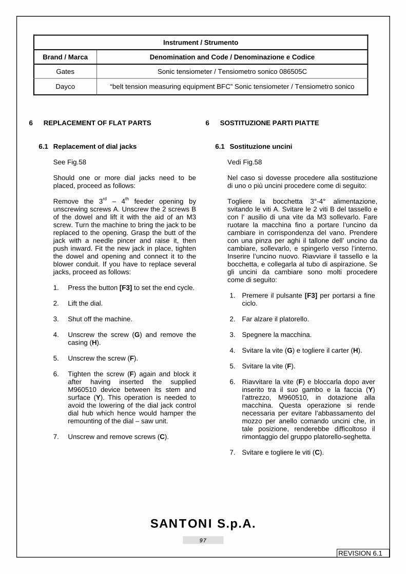
SANTONI S.p.A.
97
REVISION 6.1
Instrument / Strumento
Brand / Marca Denomination and Code / Denominazione e Codice
Gates Sonic tensiometer / Tensiometro sonico 086505C
Dayco “belt tension measuring equipment BFC” Sonic tensiometer / Tensiometro sonico
6 REPLACEMENT OF FLAT PARTS
6.1 Replacement of dial jacks
See Fig.58 Should one or more dial jacks need to be placed, proceed as follows: Remove the 3rd – 4th feeder opening by unscrewing screws A. Unscrew the 2 screws B of the dowel and lift it with the aid of an M3 screw. Turn the machine to bring the jack to be replaced to the opening. Grasp the butt of the jack with a needle pincer and raise it, then push inward. Fit the new jack in place, tighten the dowel and opening and connect it to the blower conduit. If you have to replace several jacks, proceed as follows: 1. Press the button [F3] to set the end cycle.
2. Lift the dial.
3. Shut off the machine.
4. Unscrew the screw (G) and remove the casing (H).
5. Unscrew the screw (F).
6. Tighten the screw (F) again and block it after having inserted the supplied M960510 device between its stem and surface (Y). This operation is needed to avoid the lowering of the dial jack control dial hub which hence would hamper the remounting of the dial – saw unit.
7. Unscrew and remove screws (C).
6 SOSTITUZIONE PARTI PIATTE
6.1 Sostituzione uncini Vedi Fig.58 Nel caso si dovesse procedere alla sostituzione di uno o più uncini procedere come di seguito:
Togliere la bocchetta 3°-4° alimentazione, svitando le viti A. Svitare le 2 viti B del tassello e con l’ ausilio di una vite da M3 sollevarlo. Fare ruotare la macchina fino a portare l’uncino da cambiare in corrispondenza del vano. Prendere con una pinza per aghi il tallone dell’ uncino da cambiare, sollevarlo, e spingerlo verso l’interno. Inserire l’uncino nuovo. Riavviare il tassello e la bocchetta, e collegarla al tubo di aspirazione. Se gli uncini da cambiare sono molti procedere come di seguito: 1. Premere il pulsante [F3] per portarsi a fine
ciclo. 2. Far alzare il platorello.
3. Spegnere la macchina.
4. Svitare la vite (G) e togliere il carter (H).
5. Svitare la vite (F).
6. Riavvitare la vite (F) e bloccarla dopo aver
inserito tra il suo gambo e la faccia (Y) l’attrezzo, M960510, in dotazione alla macchina. Questa operazione si rende necessaria per evitare l’abbassamento del mozzo per anello comando uncini che, in tale posizione, renderebbe difficoltoso il rimontaggio del gruppo platorello-seghetta.
7. Svitare e togliere le viti (C).

SANTONI S.p.A.
98
REVISION 6.1
8. Use the supplied M960460 device to
unscrew the bush (D) (extractor) for the extraction of the dial – saw unit.
9. Replace the damaged dial jacks and
remount the dial – saw unit by carrying out the operations in opposite order from position 6 to position 4. Be sure that during this phase the pin (E) is positioned properly and insert and tighten the screws (C) in cross order.
8. Con l’attrezzo in dotazione M/C, M960460, svitare la bussola (D) (estrattore) che estrae il gruppo platorello-seghetta.
9. Sostituire gli uncini danneggiati e
procedere al rimontaggio del platorello-seghetta eseguendo le operazioni in modo inverso dalla posizione 6 alla posizione 4. Fare attenzione in questa fase di mettere in posizione corretta la spina (E) e avvitare “a croce” le viti (C).
Fig. 58

SANTONI S.p.A.
99
REVISION 6.1
6.2 Replacement of sinkers
The sinker is removed through the slot (S) (see Fig.60), located on the sinker cap. Proceed as follows: 1. Remove the hub (A) by unscrewing the
screw (B). 2. Grab the sinker butt with the relevant
pliers, push inwards and lift the sinker as shown by the arrows in Fig.59. Then remove the sinker.
6.2 Sostituzione platine L’estrazione della platina avviene attraverso lo spacco (S) (vedi Fig.60), esistente sul coperchio platine e procedendo nel seguente modo: 1. Smontare il tassello (A) svitando la vite (B). 2. Prendere la platina con l’apposita pinza,
spingere verso l’esterno e alzare la platina come mostrano le frecce in Fig.59, procedere quindi all’estrazione.
Fig.59 Fig.60
3. The re-assembly of the sinker is to be carried out by grabbing it with the relevant pliers. Then push it downwards and towards the front so that it passes in front of the spring which must enter into its seat on the sinker rear (fig. 60).
4. Once the operation completed, remount
the hub (A) and tighten the screw (B) .
3. Per rimontare la platina, prenderla con l’apposita pinza, inserirla nel vano e spingerla verso l’esterno e poi verso il basso fino a che entra nella sede (fig. 60).
4. Terminata la sostituzione rimontare il
tassello (A) e bloccare la vite (B) .

SANTONI S.p.A.
100
REVISION 6.1
Fig. 60
6.3 Needle replacement See Fig.61 Proceed as follows to remove or insert a needle: REMOVAL 1. Turn the cylinder with the electronic
handle, position the needle to be replaced near the clearing point on the plate between feed n. 5 and n. 6 (Fig.61).
2. Take the supplied pliers and grip the
needle butt, lower it and remove it in sequence until the needle head has come out of the holding springs. Now complete the removal.
Removal of needle with broken butt. 3. Grip the damaged needle with the pliers,
open the latch and break its head. Then insert it below the needle stem to be replaced in order to extract it from the outside face of the cylinder; then complete removal as described above.
6.3 Sostituzione aghi. Vedi Fig.61 Qualora si debba estrarre o inserire un ago si proceda nel seguente modo: ESTRAZIONE 1. Far ruotare il cilindro con la manovella
elettronica, posizionare l’ago da sostituire in corrispondenza dello scarico sul piatto tra la 5ª e la 6ª alimentazione (Fig.61).
2. Premunirsi della pinza datavi in dotazione e
prendere il tallone dell’ago, abbassarlo ed estrarlo in sequenza fino a quando la testina dell’ago ha oltrepassato le molle di contenimento, a questo punto completare l’estrazione.
Estrazione dell’ago con tallone rotto. 3. Prendere con la pinza un ago già
danneggiato, aprire la linguetta e rompergli la testina, quindi inserirlo sotto lo stelo dell’ago da sostituire in modo da estrarlo dal profilo esterno del cilindro; si proceda poi all’estrazione come spiegato precedentemente.

SANTONI S.p.A.
101
REVISION 6.1
NEEDLE INSERTING 4. Open the needle latch and grip it with the
pliers at the middle of the stem. 5. Insert it with its head into the cylinder free
slot and below the holding springs. 6. Take it once again by the butt and insert
it.
INSERIMENTO 4. Aprire la linguetta dell’ago e prenderlo con
la pinza a metà dello stelo. 5. Inserirlo con la testina nello spacco libero
del cilindro e sotto le molle di contenimento. 6. Riprenderlo al tallone e completare
l’iserimento.
Fig. 61

SANTONI S.p.A.
102
REVISION 6.1
6.4 Jack replacement
See Fig.62 Should one or more jacks need to be replaced, proceed as follows to carry out this operation properly: 1. Remove the 2nd electronic drum from
the 5th feeder 2. By means of the electronic handle turn
the cylinder so that the jack in question is positioned near the clearing point (B) on the jack dial at the slit on the drum removed. Remove the jack cap cam (C) by unscrewing screw (A).
3. By means of the specific pliers (E) push
the jack upwards until it comes out of its seat.
4. Once this operation is completed, take
the jack with the pliers and by turning it outwards lower it to the clearing point (B), as shown in the figure, to remove it completely.
Proceed as follows if the jack is to be inserted into the cylinder slot instead: 5. By means of the same pliers take hold
of the jack and insert into the cylinder slot and push it upwards and inwards.
6. Once the jack is positioned on the
bottom of the slot, use the pliers to push downwards as shown in the figure until it touches the bottom of the jack control dial (F). If more than one jack is to be inserted, said procedure needs to be repeated various times. Remember to remount the jack cover cam (C) upon completing the operation.
6.4 Sostituzione selettori Vedi Fig.62 Nel caso in cui si presentasse l’eventualità, per un qualsiasi motivo di sostituire uno o più selettori, comportarsi, al fine di eseguire correttamente tale operazione, nel modo sotto descritto: 1. Togliere il 2° tamburino elettronico della
5° alimentazione. 2. Tramite la manovella elettronica, ruotare il
cilindro in modo tale che il selettore in questione, venga a trovarsi in corrispondenza dello scarico (B) ricavato sull’anello selettori in corrispondenza dello spacco del tamburino tolto. Togliere la camma copertura selettori (C) svitando la vite (A)
3. Per mezzo dell’apposita pinza (E)
spingere il selettore verso l’alto in modo da farlo uscire dalla propria sede.
4. Una volta eseguita tale operazione,
afferrare il selettore con la pinza e facendolo ruotare verso l’esterno abbassarlo nello scarico (B); come rappresentato in figura, in modo da poterlo estrarre completamente.
Al contrario, per inserire il selettore nello spacco del cilindro, agire nel seguente modo: 5. Sempre con l’apposita pinza, afferrare il
selettore ed infilarlo nello spacco del cilindro spingendolo dal basso verso l’alto e contemporaneamente verso l’interno.
6. Una volta posizionato il selettore sul fondo
dello spacco, con le becche della pinza, spingerlo verso il basso come in figura, in modo tale che vada in battuta sul fondo dell’anello comando selettori (F). Se i selettori sono più di uno ripetere le operazioni più volte, ricordandosi alla fine di rimontare la camma copertura selettori (C).

SANTONI S.p.A.
103
REVISION 6.1
Fig.62

SANTONI S.p.A.
104
REVISION 6.1
6.5 Replacement of intermediate jacks
See Fig. 63 Remove the lock on the 4th feeder by unscrewing screw X. Remove the dowel on the counter-ring by unscrewing screw Y. Using a needle pincer, grasp the jack to be replaced and remove it. Insert the new jack, pushing it firmly against the cylinder. Replace the dowel and lock.
6.5 Sostituzione selettori intermedi: Vedi Fig.63 Togliere la serratura della 4ª alimentazione svitando la vite X. Togliere il tassello sul controanello svitando la vite Y. Con una pinza per aghi prendere il selettore da cambiare, ed estrarlo. Inserire il selettore nuovo, spingendolo bene contro il cilindro. Riavvitare il tassello e la serratura.
Fig.63

SANTONI S.p.A.
105
REVISION 6.1
7 SUPPLIED INSTRUMENTS AND CALIPERS
7.1 Calipers supplied List of supplied equipment for every seto of 1 to 20 machines to be repeated for any additional set, unless stipulated otherwise in the contract. See Fig. 7-1-1
7 DOTAZIONE ATTREZZI E CALIBRI
7.1 Calibri in dotazione Elenco dotazione per ogni gruppo da 1 a 20 macchine da ripetersi per ogni ulteriore gruppo, salvo diversi accordi contrattuali. Vedi Fig. 7-1-1
Ref / Rif. Code / Codice • Name • Denominazione Q.ty / Q.tà
1 M960280 • Stitch cam height caliper • Calibro altezza triangolo 1
2 D3960280 • Needle passage caliper • Calibro passaggio aghi 1
3 M960440 • Entry needle passage caliper – gauges 16-32 • Fin. calibro passaggio aghi in entrata 1
4 M960490 • LVDT adjustment caliper • Calibro per registrazione LVDT 1
M960591 • Box height caliper • Calibro altezza scatolina
M960780 • Box positioning shims • Spessori posizionamento scatolina
5
M960790 • Box positioning shims • Spessori posizionamento scatolina
1
M960340 • 12” sinker cap bearing adjustment caliper • Calibro regol. cusc. Cop. Plat. 12”
M960260 • 13” sinker cap bearing adjustment caliper • Calibro regol. cusc. Cop. Plat. 13”
M960360 • 14” sinker cap bearing adjustment caliper • Calibro regol. cusc. Cop. Plat. 14”
M960350 • 15” sinker cap bearing adjustment caliper • Calibro regol. cusc. Cop. Plat. 15”
M960480 • 16” sinker cap bearing adjustment caliper • Calibro regol. cusc. Cop. Plat. 16”
6
M960750 • 17” sinker cap bearing adjustment caliper • Calibro regol. cusc. Cop. Plat. 17”
1
7.1.2. Tools supplied List of tools supplied with the first machine order, unless otherwise agreed upon (see fig. 7.1.2).
7.1.2 Attrezzi in dotazione Elenco attrezzi in dotazione al primo ordine di macchine, salvo diversi accordi contrattuali (vedi Fig. 7.1.2).
Ref / Rif. Code / Codice • Name • Denominazione Q.ty / Q.tà
1 M960460 • Lever for dial ring • Leva x anello mont. ghiera 1
2 M960550 • Cam block support plate • Piastra supporto serrature 1
3 M960410 • Device for gluing yarn fingers • Attrezzo per incollare tubetti guidafili 1
4 M960510 • Hub support device for dial jack control dial • Attrezzo sostegno mozzo per anello comando uncini 1

SANTONI S.p.A.
106
REVISION 6.1
Fig.7-1-1
Fig.7-1-2

SANTONI S.p.A.
107
REVISION 6.1
7.2 Flat parts supplied
7.2.1 Supplied flat parts for (GG75)
See Fig. 7.2-1 (Quantity for each machine)
7.2 Dotazione parti piatte 7.2.1 Dotazione parti piatte per (GG75)
Vedi Fig. 7.2-1 (Quantità date per ogni macchina)
Ref / Rif. Code / Codice • Name • Denominazione Q.ty / Q.tà
Needles / Aghi
1 AG 7034.G0631 • (GROZ HOFA Needle Spec. 7034 G0631 Butt 6) • (Ago GROZ HOFA Spec. 7034 G0631 Tallone da 6) 100
2 AG 7034.G0633 • (GROZ HOFA Needle Spec. 7034 G0633 Butt 8) • (Ago GROZ HOFA Spec. 7034 G0633 Tallone da 8) 100
Sinkers / Platine
M040170 • T.A. sinker (Ref. Kern) 20 1500 000 G • Platina T.A. (Rif. Kern) 20 1500 000 G 50
3 M040160 • T.B. sinker (Rif. Kern) 20 1501 001 G
• Platina T.B. (Rif. Kern) 20 1501 001 G 150
Dial Jacks / Uncini
M050020 • T.A. dial jack (Ref. Christoph Liebers 3457/81A) • Uncino T.A. (Rif. Christoph Liebers 3457/81A) 50
4 M050010 • T.B. dial jack (Ref. Christoph Liebers 3457/82A)
• Uncino T.B. (Rif. Christoph Liebers 3457/82A) 150
Intermediate Jacks / Selettori Intermedi
M031360 • Intermediate heel jack 6 • Selettore intermedio tall.6 100
5 M031370 • Intermediate heel jack 8
• Selettore intermedio tall.8 50
Jacks / Selettori
6 M901450 • Diagonal 16 jacks for needle GG75 • Diagonale 16 selettori per ago GG75 10

SANTONI S.p.A.
108
REVISION 6.1
Fig.7.2-1
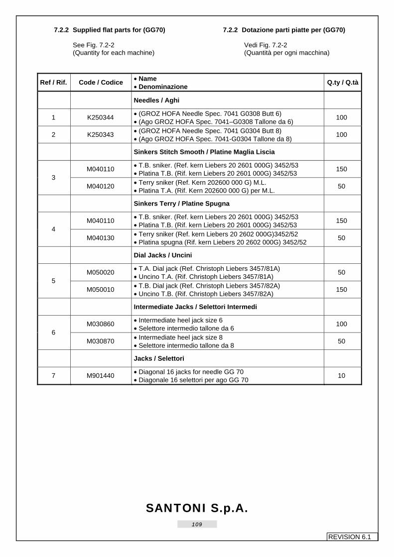
SANTONI S.p.A.
109
REVISION 6.1
7.2.2 Supplied flat parts for (GG70)
See Fig. 7.2-2 (Quantity for each machine)
7.2.2 Dotazione parti piatte per (GG70) Vedi Fig. 7.2-2 (Quantità per ogni macchina)
Ref / Rif. Code / Codice • Name • Denominazione Q.ty / Q.tà
Needles / Aghi
1 K250344 • (GROZ HOFA Needle Spec. 7041 G0308 Butt 6) • (Ago GROZ HOFA Spec. 7041–G0308 Tallone da 6) 100
2 K250343 • (GROZ HOFA Needle Spec. 7041 G0304 Butt 8) • (Ago GROZ HOFA Spec. 7041-G0304 Tallone da 8) 100
Sinkers Stitch Smooth / Platine Maglia Liscia
M040110 • T.B. sniker. (Ref. kern Liebers 20 2601 000G) 3452/53 • Platina T.B. (Rif. kern Liebers 20 2601 000G) 3452/53 150
3 M040120 • Terry sniker (Ref. Kern 202600 000 G) M.L.
• Platina T.A. (Rif. Kern 202600 000 G) per M.L. 50
Sinkers Terry / Platine Spugna
M040110 • T.B. sniker. (Ref. kern Liebers 20 2601 000G) 3452/53 • Platina T.B. (Rif. kern Liebers 20 2601 000G) 3452/53 150
4 M040130 • Terry sniker (Ref. kern Liebers 20 2602 000G)3452/52
• Platina spugna (Rif. kern Liebers 20 2602 000G) 3452/52 50
Dial Jacks / Uncini
M050020 • T.A. Dial jack (Ref. Christoph Liebers 3457/81A) • Uncino T.A. (Rif. Christoph Liebers 3457/81A) 50
5 M050010 • T.B. Dial jack (Ref. Christoph Liebers 3457/82A)
• Uncino T.B. (Rif. Christoph Liebers 3457/82A) 150
Intermediate Jacks / Selettori Intermedi
M030860 • Intermediate heel jack size 6 • Selettore intermedio tallone da 6 100
6 M030870 • Intermediate heel jack size 8
• Selettore intermedio tallone da 8 50
Jacks / Selettori
7 M901440 • Diagonal 16 jacks for needle GG 70 • Diagonale 16 selettori per ago GG 70 10

SANTONI S.p.A.
110
REVISION 6.1
Fig.7.2-2

SANTONI S.p.A.
111
REVISION 6.1
7.2.3 Supplied flat parts for (GG54)
See Fig. 7.2-3 (Quantity for each machine)
7.2.3 Dotazione parti piatte per (GG54) Vedi Fig. 7.2-3 (Quantità per ogni macchina)
Ref / Rif. Code / Codice • Name • Denominazione Q.ty / Q.tà
Needles / Aghi
1 K250346 • (GROZ VO Needle 70.50-G103 Butt 6) • (Ago GROZ VO 70.50-G103 Tallone da 6) 100
2 K250345 • (GROZ VO Needle 70.50-G102 Butt 7.9) • (Ago GROZ VO 70.50-G102 Tallone da 7.9) 100
Sinkers / Platine
M040130 • SPUGNA sinker (Ref. Kern Liebers 20 2602 000G) 3452/52 • Platina SPUGNA (kern Liebers 20 2602 000G) 3452/52 50
M040110 • T.B. sinker. (Ref. kern Liebers 20 2601 000G) 3452/53 • Platina T.B. (kern Liebers 20 2601 000G) 3452/53 100 3
M040120 • Sinker T.A. (kern Liebers 10 2600 000G) plain stitch • Platina T.A. (kern liebers 20 2600 000 G) Maglia Liscia 50
Dial Jacks / Uncini
M050020 • T.A. Dial jack (Ref. Christoph Liebers 3457/81A) • Uncino T.A. (Rif. Christoph Liebers 3457/81A) 50
4 M050010 • T.B. Dial jack (Ref. Christoph Liebers 3457/82A)
• Uncino T.B. (Rif. Christoph Liebers 3457/82A) 100
Intermediate Jacks / Selettori Intermedi
M031380 • Intermediate heel jack size 6 • Selettore intermedio tallone da 6 100
5 M031390 • Intermediate heel jack size 8
• Selettore intermedio tallone da 8 50
Jacks / Selettori
6 M901460 • Diagonal 16 jacks for needle GG 54 • Diagonale 16 selettori per ago GG 54 10

SANTONI S.p.A.
112
REVISION 6.1
Fig.7.2-3

SANTONI S.p.A.
113
REVISION 6.1
7.2.4 Supplied flat parts for (GG48)
See Fig. 7.2-4 (Quantity for each machine)
7.2.4 Dotazione parti piatte per (GG48) Vedi Fig. 7.2-4 (Quantità per ogni macchina)
Ref / Rif. Code / Codice • Name • Denominazione Q.ty / Q.tà
Needles / Aghi
1 K250063 • (GROZ VO Needle 70.60-G015 Butt 6) • (Ago GROZ VO 70.60-G015 Tallone da 6) 100
2 K250110 • (GROZ VO Needle 70.60-G009 Butt 7.9) • (Ago GROZ VO 70.60-G009 Tallone da 7.9) 100
Sinkers / Platine
M040150 • T.A. Sinker (kern Liebers 20 2603 000G) 3452/53 0.25mm • Platina T.A. (kern Liebers 20 2603 000G) 3452/53 0.25mm 50
3 M040140 • T.B. Sinker (kern Liebers 20 2604 000G) 3452/53 T 0.25mm
• Platina T.B. (kern Liebers 20 2604 000G) 3452/53 T 0.25mm 150
Dial Jacks / Uncini
M050020 • T.A. Dial jack (Ref. Christoph Liebers 3457/81A) • Uncino T.A. (Rif. Christoph Liebers 3457/81A) 50
4 M050010 • T.B. Dial jack (Ref. Christoph Liebers 3457/82A)
• Uncino T.B. (Rif. Christoph Liebers 3457/82A) 150
Intermediate Jacks / Selettori Intermedi
M031560 • Intermediate heel jack size 6 • Selettore intermedio tallone da 6 100
5 M031570 • Intermediate heel jack size 8
• Selettore intermedio tallone da 8 50
Jacks / Selettori
6 M901460 • Diagonal 16 jacks for needle GG 48 • Diagonale 16 selettori per ago GG 48 10

SANTONI S.p.A.
114
REVISION 6.1
Fig.7.2-4

SANTONI S.p.A.
115
REVISION 6.1
7.3 Mechanical parts supplied
See Fig. 7.3 (Quantity for each machine)
7.3 Dotazione parti meccaniche Vedi Fig. 7.3 (Quantità per ogni macchina)
Ref / Rif. Code / Codice • Name • Denominazione Q.ty / Q.tà
M070430 • Steel tube • Tubetto acciaio 4
1 M070580 • Ceramic tube
• Tubetto ceramica 6
2 M070370 • Ceramic tube • Tubetto ceramica 5
3 K307055 • M25X4 dowel • Grano M25X4 10
4 M080030 • Yarn cutter • Coltellino tagliafilo 1
5 K418095 • Antiballon yarn finger DYW 2L • Guidafilo antiballon DYW 2L 16
6 K371372 • Black comb for IRO • Pettine nero per IRO 24
7 K371370 • Yellow comb for IRO • Pettine giallo per IRO 8
8 M221800 • Yarn finger tube fastening adjustment cylinder • Cilindretto regolazione fissaggio tubetto guidafili 6
Fig. 7.3

SANTONI S.p.A.
116
REVISION 6.1
7.4 Electrical parts supplied
See Fig. 7.4 (Quantity for each machine)
7.4 Dotazione parti elettriche Vedi Fig. 7.4 (Quantità per ogni macchina)
Ref / Rif. Code / Codice • Name • Denominazione Q.ty / Q.tà
1 0405100 • Glass fuse 5x20 1A • Fusibile vetro 5x20 1A 3
2 K405213 • Glass fuse 5x20 4A • Fusibile vetro 5x20 4A 3
3 0405110 • Glass fuse 5X20 6.3A • Fusibile vetro 5x20 6.3A 10
4 0405130 • Glass fuse 5x20 3.15A • Fusibile vetro 5x20 3,15A 3
5 0405062 • Legrand Fuse art. 130 2A • Fusibile Legrand art. 130 2A 1
6 0405066 • Legrand Fuse art. 130 6A • Fusibile Legrand art. 130 6A 3
7 K405233 • Ceramic fuse 10.3x38 2AT • Fusibile ceramica 10.3x38 2AT 3
8 K405234 • Ceramic fuse 10.3x38 6AT • Fusibile ceramica 10.3x38 6AT 2
9 K405216 • Legrand Fuse art. 130 16A • Fusibile Legrand art. 130 16A 1
10 K405222 • Fuse. 6.3x32 4AT • Fusibile 6.3x32 4AT 3
11 0403360 • Female contacts Modu 2 • Contatti femmina Modu 2 10
12 0403350 • Female contacts Modu 1 • Contatti femmina Modu 1 10
13 6900158 • Disks for dis 2HC* • Dischi per dis 2HC* 3
* Each machine n.1 must be given the base program
* Dare a ogni 1° M/C con programma base

SANTONI S.p.A.
117
REVISION 6.1
Fig.7.4

SANTONI S.p.A.
118
REVISION 6.1
7.5 Wrenches and pliers supplied
List of supplied equipment for each unit from 1 to 20 machines to be repeated for any further unit, save for agreements envisaging otherwise. See Fig. 7.5
7.5 Dotazione chiavi e pinze Elenco dotazione per ogni gruppo da 1 a 20 macchine da ripetersi per ogni ulteriore gruppo, salvo diversi accordi contrattuali. Vedi Fig. 7.5
Ref / Rif. Code / Codice • Name • Denominazione Q.ty / Q.tà
1 UC210055 • Wrench 5 – 5,5 • Chiave fissa 5 – 5,5 1
2 UC2100607 • Wrench 6 – 7 • Chiave fissa 6 – 7 1
3 UC2100809 • Wrench 8 – 9 • Chiave fissa 8 – 9 1
4 UC2101011 • Wrench 10 – 11 • Chiave fissa 10 - 11 1
5 UC2101213 • Wrench 12 – 13 • Chiave fissa 12 - 13 1
6 UC2101415 • Wrench 14 – 15 • Chiave fissa 14 - 15 1
7 UC2101617 • Wrench 16 – 17 • Chiave fissa 16 - 17 1
8 UC2700030 • Articulated setscrew wrench 3 • Chiave brugola snodata 3 1
9 UC2700040 • Articulated setscrew wrench 4 • Chiave brugola snodata 4 1
10 UC2700050 • Articulated setscrew wrench 5 • Chiave brugola snodata 5 1
11 UC2220020 • “T” setscrew wrench 2 • Chiave brugola a “T” 2 1
12 UC2220025 • “T” setscrew wrench 2.5 • Chiave brugola a “T” 2,5 1
13 UC2220030 • “T” setscrew wrench 3 • Chiave brugola a “T” 3 1
14 UC2220040 • “T” setscrew wrench 4 • Chiave brugola a “T” 4 1
15 UC2220050 • “T” setscrew wrench 5 • Chiave brugola a “T” 5 1
16 UC2220060 • “T” setscrew wrench 6 • Chiave brugola a “T” 6 1
17 UC2220080 • “T” setscrew wrench 8 • Chiave brugola a “T” 8 1
18 UC2200015 • Setscrew wrench 1,5 • Chiave brugola 1,5 1
19 UC2200020 • Setscrew wrench 2 • Chiave brugola 2 1
20 UC2200025 • Setscrew wrench 2,5 • Chiave brugola 2,5 1
21 UC2200030 • Setscrew wrench 3 • Chiave brugola 3 1
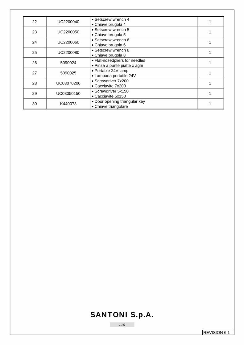
SANTONI S.p.A.
119
REVISION 6.1
22 UC2200040 • Setscrew wrench 4 • Chiave brugola 4 1
23 UC2200050 • Setscrew wrench 5 • Chiave brugola 5 1
24 UC2200060 • Setscrew wrench 6 • Chiave brugola 6 1
25 UC2200080 • Setscrew wrench 8 • Chiave brugola 8 1
26 5090024 • Flat-nosedpliers for needles • Pinza a punte piatte x aghi 1
27 5090025 • Portable 24V lamp • Lampada portatile 24V 1
28 UC03070200 • Screwdriver 7x200 • Cacciavite 7x200 1
29 UC03050150 • Screwdriver 5x150 • Cacciavite 5x150 1
30 K440073 • Door opening triangular key • Chiave triangolare 1

SANTONI S.p.A.
120
REVISION 6.1
Fig.7.5

SANTONI S.p.A.
REVISION 6.1

SANTONI S.p.A.
REVISION 6.1

SANTONI S.p.A.

ELECTRONIC HOSIERY KNITTING MACHINES
Santoni S.p.A Via Carlo Fenzi, 14 - 25135 Brescia - ITALY
Tel. +39 030 376711 r.a. - Fax +39 030 3767242 www.santoni.it - e-mail:[email protected]


![1 1 1 1 1 1 1 ¢ 1 , ¢ 1 1 1 , 1 1 1 1 ¡ 1 1 1 1 · 1 1 1 1 1 ] ð 1 1 w ï 1 x v w ^ 1 1 x w [ ^ \ w _ [ 1. 1 1 1 1 1 1 1 1 1 1 1 1 1 1 1 1 1 1 1 1 1 1 1 1 1 1 1 ð 1 ] û w ü](https://static.fdocuments.us/doc/165x107/5f40ff1754b8c6159c151d05/1-1-1-1-1-1-1-1-1-1-1-1-1-1-1-1-1-1-1-1-1-1-1-1-1-1-w-1-x-v.jpg)


![1 $SU VW (G +LWDFKL +HDOWKFDUH %XVLQHVV 8QLW 1 X ñ 1 … · 2020. 5. 26. · 1 1 1 1 1 x 1 1 , x _ y ] 1 1 1 1 1 1 ¢ 1 1 1 1 1 1 1 1 1 1 1 1 1 1 1 1 1 1 1 1 1 1 1 1 1 1 1 1 1 1](https://static.fdocuments.us/doc/165x107/5fbfc0fcc822f24c4706936b/1-su-vw-g-lwdfkl-hdowkfduh-xvlqhvv-8qlw-1-x-1-2020-5-26-1-1-1-1-1-x.jpg)


