SLV-LX80S - Diagramas dediagramas.diagramasde.com/otros/SLV-LX80S.pdfcommander to operate this VCR...
70
SLV-LX80S RMT-V294A Chilean Model Mexican Model SERVICE MANUAL VIDEO CASSETTE RECORDER S MECHANISM Refer to the SERVICE MANUAL of VHS MECHANICAL ADJUSTMENT for MECHANICAL ADJUSTMENTS. (9-921-748-11) SPECIFICATIONS 1 2 3 4 5 6 7 8 9 0 g System Format VHS NTSC standard Video recording system Rotary head helical scanning FM system Video heads Double azimuth four heads Video signal NTSC color, EIA standards Tape speed SP: 33.35 mm/s (1 3 /8 inches/s) EP: 11.11 mm/s ( 7 /16 inches/s) LP: 16.67 mm/s ( 11 /16 inches/s), playback only Maximum recording/playback time 9 hrs. in EP mode (with T-180 tape) Fast-forward and rewind time Approx. 3 min. (with T-120 tape) Tuner section Channel coverage VHF 2 to 13 UHF 14 to 69 CATV A-8 to A-1, A to W, W+1 to W+84 Antenna 75-ohm antenna terminal for VHF/UHF Input and outputs LINE-1 IN and -2 IN VIDEO IN, phono jack (1 each) Input signal: 1 Vp-p, 75 ohms, unbalanced, sync negative AUDIO IN, phono jacks (2 each) Input level: 327 mVrms Input impedance: more than 47 kilohms LINE OUT VIDEO OUT, phono jack (1) Output signal: 1 Vp-p, 75 ohms, unbalanced, sync negative AUDIO OUT, phono jacks (2) Standard output: 327 mVrms Load impedance: 47 kilohms Output impedance: less than 10 kilohms Timer section Clock Quartz locked Timer indication 12-hour cycle Timer setting 8 programs (max.) Power back-up Built-in self-charging capacitor Back-up duration: up to 1 hour at a time General Power requirements 110 V AC to 240 V AC, 50/60 Hz (SLV-LX80S CS) 120 V AC, 60 Hz (SLV-LX80S MX) Power consumption 17W Operating temperature 5°C to 40°C (41°F to 104°F) Storage temperature -20°C to 60°C (-4°F to 140°F) Dimensions Approx. 430 ✕ 97 ✕ 292 mm (w/h/d) (Approx. 17 ✕ 3 ✕ 11 inches) including projecting parts and controls Mass Approx. 4.1 kg (9 lb 1 oz) Supplied accessories Remote commander (1) Size AA (R6) batteries (2) 75-ohm coaxial cable with F-type connectors (1) Audio/video cable (1) (3-phono to 3-phono) Plug adaptor (1) (SLV-LX80S CS only) Design and specifications are subject to change without notice ENERGY STAR ® is a U.S. registered mark. As an ENERGY STAR ® Partner, Sony Corporation has determined that this product meets the ENERGY STAR ®
Transcript of SLV-LX80S - Diagramas dediagramas.diagramasde.com/otros/SLV-LX80S.pdfcommander to operate this VCR...

— 1 —
SLV-LX80SRMT-V294A
Chilean Model
Mexican ModelSERVICE MANUAL
VIDEO CASSETTE RECORDER
S MECHANISM
Refer to the SERVICE MANUAL of VHS MECHANICALADJUSTMENT for MECHANICAL ADJUSTMENTS.(9-921-748-11)
SPECIFICATIONS
1 2 3
4 5 6
7 8 9
0
g
System
Format
VHS NTSC standard
Video recording system
Rotary head helical scanning FM system
Video heads
Double azimuth four heads
Video signal
NTSC color, EIA standards
Tape speed
SP: 33.35 mm/s (1 3/8 inches/s)
EP: 11.11 mm/s (7/16 inches/s)
LP: 16.67 mm/s (11/16 inches/s),
playback only
Maximum recording/playback time
9 hrs. in EP mode (with T-180 tape)
Fast-forward and rewind time
Approx. 3 min. (with T-120 tape)
Tuner section
Channel coverage
VHF 2 to 13
UHF 14 to 69
CATV A-8 to A-1, A to W, W+1 to W+84
Antenna
75-ohm antenna terminal for VHF/UHF
Input and outputs
LINE-1 IN and -2 IN
VIDEO IN, phono jack (1 each)
Input signal: 1 Vp-p, 75 ohms, unbalanced, sync
negative
AUDIO IN, phono jacks (2 each)
Input level: 327 mVrms
Input impedance: more than 47 kilohms
LINE OUT
VIDEO OUT, phono jack (1)
Output signal: 1 Vp-p, 75 ohms, unbalanced,sync negative
AUDIO OUT, phono jacks (2)
Standard output: 327 mVrms
Load impedance: 47 kilohms
Output impedance: less than 10 kilohms
Timer section
Clock
Quartz locked
Timer indication
12-hour cycle
Timer setting
8 programs (max.)
Power back-up
Built-in self-charging capacitor
Back-up duration: up to 1 hour at a time
General
Power requirements110 V AC to 240 V AC, 50/60 Hz
(SLV-LX80S CS)
120 V AC, 60 Hz
(SLV-LX80S MX)
Power consumption
17W
Operating temperature
5°C to 40°C (41°F to 104°F)
Storage temperature
-20°C to 60°C (-4°F to 140°F)
Dimensions
Approx. 430 97 292 mm (w/h/d)
(Approx. 17 3 11 inches) including
projecting parts and controls
Mass
Approx. 4.1 kg (9 lb 1 oz)
Supplied accessories
Remote commander (1)
Size AA (R6) batteries (2)
75-ohm coaxial cable with F-type connectors (1)Audio/video cable (1) (3-phono to 3-phono)Plug adaptor (1) (SLV-LX80S CS only)
Design and specifications are subject to changewithout notice
ENERGY STAR® is a U.S. registered mark.
As an ENERGY STAR® Partner, Sony Corporationhas determined that this product meets theENERGY STAR®

— 2 —
SAFETY-RELATED COMPONENT WARNING!!
COMPONENTS IDENTIFIED BY MARK ! OR DOTTED LINE WITHMARK ! ON THE SCHEMATIC DIAGRAMS AND IN THE PARTSLIST ARE CRITICAL TO SAFE OPERATION. REPLACE THESECOMPONENTS WITH SONY PARTS WHOSE PART NUMBERSAPPEAR AS SHOWN IN THIS MANUAL OR IN SUPPLEMENTSPUBLISHED BY SONY.
SAFETY CHECK-OUT
After correcting the original service problem, perform the following
safety checks before releasing the set to the customer.
1. Check the area of your repair for unsoldered or poorly-solderedconnections. Check the entire board surface for solder splashesand bridges.
2. Check the interboard wiring to ensure that no wires are"pinched" or contact high-wattage resistors.
3. Look for unauthorized replacement parts, particularlytransistors, that were installed during a previous repair. Pointthem out to the customer and recommend their replacement.
4. Look for parts which, though functioning, show obvious signsof deterioration. Point them out to the customer andrecommend their replacement.
5. Check the B+ voltage to see it is at the values specified.
— 3 —
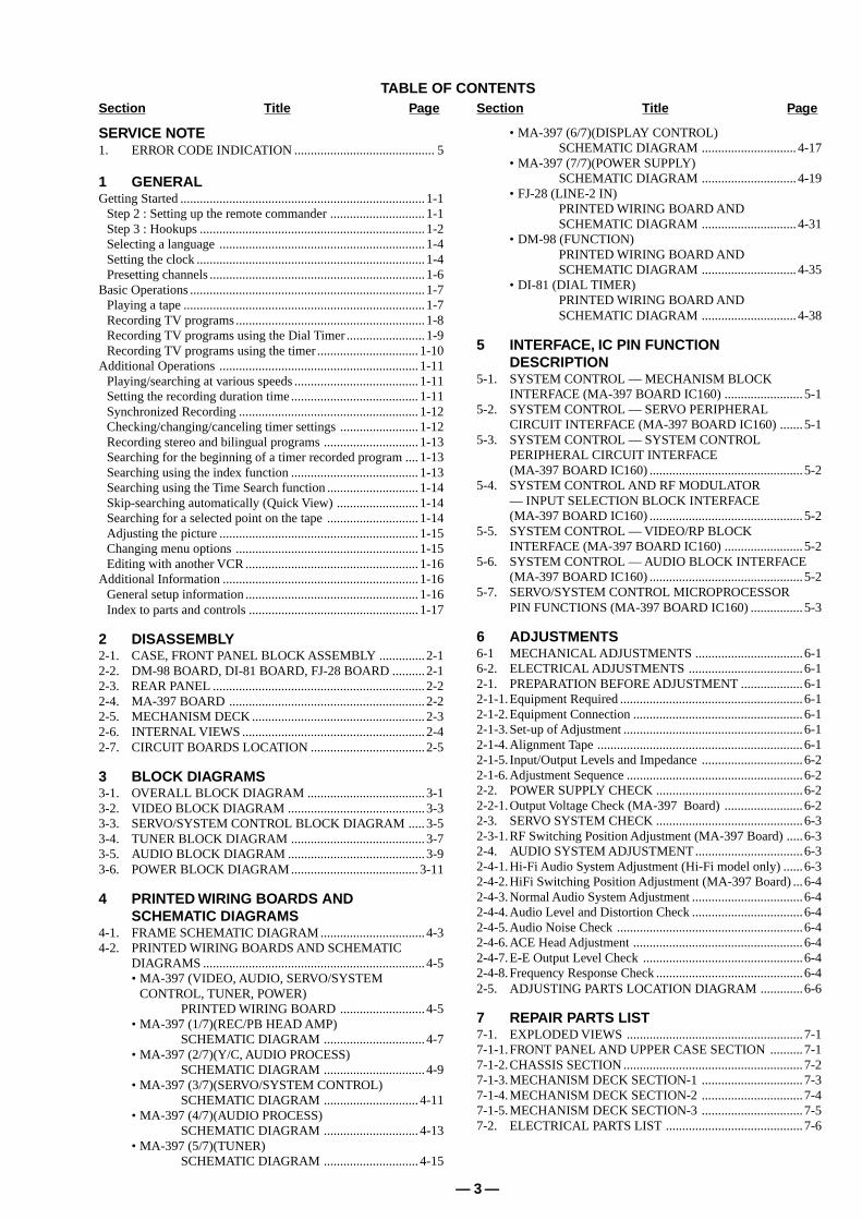
TABLE OF CONTENTSSection Title Page
SERVICE NOTE1. ERROR CODE INDICATION ........................................... 5
1 GENERALGetting Started ........................................................................... 1-1
Step 2 : Setting up the remote commander ............................. 1-1Step 3 : Hookups ..................................................................... 1-2Selecting a language ............................................................... 1-4Setting the clock ...................................................................... 1-4Presetting channels .................................................................. 1-6
Basic Operations ........................................................................ 1-7Playing a tape .......................................................................... 1-7Recording TV programs .......................................................... 1-8Recording TV programs using the Dial Timer ........................ 1-9Recording TV programs using the timer ............................... 1-10
Additional Operations ............................................................. 1-11Playing/searching at various speeds ...................................... 1-11Setting the recording duration time ....................................... 1-11Synchronized Recording ....................................................... 1-12Checking/changing/canceling timer settings ........................ 1-12Recording stereo and bilingual programs ............................. 1-13Searching for the beginning of a timer recorded program .... 1-13Searching using the index function ....................................... 1-13Searching using the Time Search function ............................ 1-14Skip-searching automatically (Quick View) ......................... 1-14Searching for a selected point on the tape ............................ 1-14Adjusting the picture ............................................................. 1-15Changing menu options ........................................................ 1-15Editing with another VCR ..................................................... 1-16
Additional Information ............................................................ 1-16General setup information ..................................................... 1-16Index to parts and controls .................................................... 1-17
2 DISASSEMBLY2-1. CASE, FRONT PANEL BLOCK ASSEMBLY .............. 2-12-2. DM-98 BOARD, DI-81 BOARD, FJ-28 BOARD .......... 2-12-3. REAR PANEL ................................................................. 2-22-4. MA-397 BOARD ............................................................ 2-22-5. MECHANISM DECK ..................................................... 2-32-6. INTERNAL VIEWS ........................................................ 2-42-7. CIRCUIT BOARDS LOCATION ................................... 2-5
3 BLOCK DIAGRAMS3-1. OVERALL BLOCK DIAGRAM .................................... 3-13-2. VIDEO BLOCK DIAGRAM .......................................... 3-33-3. SERVO/SYSTEM CONTROL BLOCK DIAGRAM ..... 3-53-4. TUNER BLOCK DIAGRAM ......................................... 3-73-5. AUDIO BLOCK DIAGRAM .......................................... 3-93-6. POWER BLOCK DIAGRAM ....................................... 3-11
4 PRINTED WIRING BOARDS ANDSCHEMATIC DIAGRAMS
4-1. FRAME SCHEMATIC DIAGRAM ................................ 4-34-2. PRINTED WIRING BOARDS AND SCHEMATIC
DIAGRAMS .................................................................... 4-5• MA-397 (VIDEO, AUDIO, SERVO/SYSTEM
CONTROL, TUNER, POWER)PRINTED WIRING BOARD .......................... 4-5
• MA-397 (1/7)(REC/PB HEAD AMP)SCHEMATIC DIAGRAM ............................... 4-7
• MA-397 (2/7)(Y/C, AUDIO PROCESS)SCHEMATIC DIAGRAM ............................... 4-9
• MA-397 (3/7)(SERVO/SYSTEM CONTROL)SCHEMATIC DIAGRAM ............................. 4-11
• MA-397 (4/7)(AUDIO PROCESS)SCHEMATIC DIAGRAM ............................. 4-13
• MA-397 (5/7)(TUNER)SCHEMATIC DIAGRAM ............................. 4-15
• MA-397 (6/7)(DISPLAY CONTROL)SCHEMATIC DIAGRAM ............................. 4-17
• MA-397 (7/7)(POWER SUPPLY)SCHEMATIC DIAGRAM ............................. 4-19
• FJ-28 (LINE-2 IN)PRINTED WIRING BOARD ANDSCHEMATIC DIAGRAM ............................. 4-31
• DM-98 (FUNCTION)PRINTED WIRING BOARD ANDSCHEMATIC DIAGRAM ............................. 4-35
• DI-81 (DIAL TIMER)PRINTED WIRING BOARD ANDSCHEMATIC DIAGRAM ............................. 4-38
5 INTERFACE, IC PIN FUNCTIONDESCRIPTION
5-1. SYSTEM CONTROL — MECHANISM BLOCKINTERFACE (MA-397 BOARD IC160) ........................ 5-1
5-2. SYSTEM CONTROL — SERVO PERIPHERALCIRCUIT INTERFACE (MA-397 BOARD IC160) ....... 5-1
5-3. SYSTEM CONTROL — SYSTEM CONTROLPERIPHERAL CIRCUIT INTERFACE(MA-397 BOARD IC160) ............................................... 5-2
5-4. SYSTEM CONTROL AND RF MODULATOR— INPUT SELECTION BLOCK INTERFACE(MA-397 BOARD IC160) ............................................... 5-2
5-5. SYSTEM CONTROL — VIDEO/RP BLOCKINTERFACE (MA-397 BOARD IC160) ........................ 5-2
5-6. SYSTEM CONTROL — AUDIO BLOCK INTERFACE(MA-397 BOARD IC160) ............................................... 5-2
5-7. SERVO/SYSTEM CONTROL MICROPROCESSORPIN FUNCTIONS (MA-397 BOARD IC160) ................ 5-3
6 ADJUSTMENTS6-1 MECHANICAL ADJUSTMENTS .................................6-16-2. ELECTRICAL ADJUSTMENTS ................................... 6-12-1. PREPARATION BEFORE ADJUSTMENT ................... 6-12-1-1.Equipment Required ........................................................ 6-12-1-2.Equipment Connection .................................................... 6-12-1-3.Set-up of Adjustment ....................................................... 6-12-1-4.Alignment Tape ............................................................... 6-12-1-5. Input/Output Levels and Impedance ............................... 6-22-1-6.Adjustment Sequence ...................................................... 6-22-2. POWER SUPPLY CHECK .............................................6-22-2-1.Output Voltage Check (MA-397 Board) ........................ 6-22-3. SERVO SYSTEM CHECK .............................................6-32-3-1.RF Switching Position Adjustment (MA-397 Board) .....6-32-4. AUDIO SYSTEM ADJUSTMENT .................................6-32-4-1.Hi-Fi Audio System Adjustment (Hi-Fi model only) ...... 6-32-4-2.HiFi Switching Position Adjustment (MA-397 Board) ... 6-42-4-3.Normal Audio System Adjustment .................................. 6-42-4-4.Audio Level and Distortion Check .................................. 6-42-4-5.Audio Noise Check .........................................................6-42-4-6.ACE Head Adjustment .................................................... 6-42-4-7.E-E Output Level Check .................................................6-42-4-8.Frequency Response Check .............................................6-42-5. ADJUSTING PARTS LOCATION DIAGRAM .............6-6
7 REPAIR PARTS LIST7-1. EXPLODED VIEWS ...................................................... 7-17-1-1.FRONT PANEL AND UPPER CASE SECTION .......... 7-17-1-2.CHASSIS SECTION ....................................................... 7-27-1-3.MECHANISM DECK SECTION-1 ............................... 7-37-1-4.MECHANISM DECK SECTION-2 ............................... 7-47-1-5.MECHANISM DECK SECTION-3 ............................... 7-57-2. ELECTRICAL PARTS LIST .......................................... 7-6
Section Title Page

— 4 —
1. ERROR CODE INDICATION• Error codes are indicated using the lower 5 digits in the fluorescent display tube.
“At this time, Colon “:” between character is not indicated.”
ERROR CODE
MODE CODE0 Power-on eject 10 FWD x1 20 REW play1 Power-on initial 11 FWD x2 21 Cas. loading2 Power-off eject 12 CUE 22 Tape loading3 Power-off stop 13 PB-pause 23 Power-off loading4 FF 14 RVS-pause 24 Mecha. error (Power on)5 REW 15 RVS x1 25 Power-on eject initial6 REC 16 RVS x2 26 Power-off eject initial7 REC- pause 17 REV 27 APC REC8 Power-on stop 18 Power-off initial 28 Cas. loading9 PB 19 Mecha. error (Power off) (No auto PB check)
0 No error1 Cam encoder error Loading direction2 Cam encoder error Unloading direction3 T reel error4 S reel error5 Capstan error6 Drum error7 Error on initializing8 Cassette loading error9 Reserve
SERVICE NOTE
Mode code indication when the error has occurred.
Error code

1-1
Gettin
g S
tarted
5Setting up the remote commander
Step 2 : Setting up the remote commander
Notes• With normal use, the batteries should last about three to six months.• If you do not use the remote commander for an extended period of time, remove the batteries
to avoid possible damage from battery leakage.• Do not use a new battery with an old one.• Do not use different types of batteries.
Inserting the batteriesInsert two size AA (R6) batteries by matching the + and – on the batteries to the diagram inside the battery compartment.
Insert the negative (–) end first, then push in and down until the positive (+) end clicks into position.
Using the remote commanderYou can use this remote commander to operate this VCR and a Sony TV. Buttons on the remote commander marked with a dot (•) can be used to operate your Sony TV.
To operate Set •TV / VIDEO to
the VCR VIDEO and point at the remote sensor at the VCR
a Sony TV •TV and point at the remote sensor at the TV
1 2 3
•TV / VIDEO
Remote sensor
continued
6 Setting up the remote commander
Controlling other TVs with the remote commanderThe remote commander is preprogrammed to control non-Sony TVs. If your TV is listed in the following table, set the appropriate manufacturer’s code number.
Now you can use the ?/1, VOL +/–, CH +/–, and TV/VIDEO buttons to control your TV. You can also use the buttons marked with a dot (•) to control a Sony TV. To control the VCR, reset •TV / VIDEO to VIDEO.
Code numbers of controllable TVs
If more than one code number is listed, try entering them one at a time until you find the one that works with your TV.
Notes• If you enter a new code number, the code number previously entered will be erased.• If the TV uses a different remote control system from the one programmed to work with the
VCR, you cannot control your TV with the remote commander.• When you replace the batteries of the remote commander, the code number may change. Set
the appropriate code number every time you replace the batteries.• When you press the AUDIO MONITOR button, your TV’s menu may appear on the TV
screen. To exit the TV menu, press the MENU button on the TV remote commander or wait until the menu disappears automatically.
1 Set •TV / VIDEO at the top of the remote commander to •TV.
2 Hold down ?/1, and enter your TV’s code number using the number buttons. Then release ?/1.
TV brandCode number
Sony 01
Akai 04
AOC 04
Centurion 12
Coronado 03
Curtis-Mathes 12
Daytron 12
Emerson 03, 04, 14
Fisher 11
General Electric 06, 10
Gold Star 03, 04, 17
Hitachi 02, 03
J.C.Penney 04, 12
JVC 09
KMC 03
Magnavox 03, 08, 12
Marantz 04, 13
MGA/Mitsubishi 04, 12, 13, 17
NEC 04, 12
Panasonic 06, 19
Philco 03, 04
Philips 08
Pioneer 16
Portland 03
Quasar 06, 18
Radio Shack 05, 14
TV brandCode number
RCA 04, 10
Sampo 12
Sanyo 11
Scott 12
Sears 07, 10, 11
Sharp 03, 05, 18
Sylvania 08, 12
Teknika 03, 08, 14
Toshiba 07
Wards 03, 04, 12
Yorx 12
Zenith 15
TV brandCode number
Gettin
g S
tarted
7Hookups
Step 3 : Hookups
Selecting the best hookup optionThere are many ways in which your VCR can be hooked up. To hook up your VCR so that it works best for you, first scan through the table below. Then use the accompanying diagrams and procedures on the following pages to set up your VCR.
If your TV has audio/video inputs, refer to pages 8 and 9 for audio/video (A/V) hookup. Then follow one of the hookups below. If your TV doesn’t have A/V inputs, go directly to one of the hookups below.
After you’ve completed the connections, follow the instructions for setup. During setup, if you need more details on the procedure described, page numbers are provided where you can find complete, step-by-step instructions.
After you’ve completed the setup, you’re ready to use your VCR. Procedures differ depending on the hookup you used. For an overview, refer to “Quick reference to using the VCR” on the back cover.
Before you get started
• Turn off the power to all equipment.• Do not connect the AC power cords until all of the connections are completed.• Be sure to make connections firmly. Loose connections may cause picture
distortion.• If your TV doesn’t match any of the examples provided, see your nearest Sony
dealer or qualified technician.
If you have Use Refer to
Antenna only, no cable TV Hookup 1 Pages 10 to 11
No cable box or cable box with only a few scrambled channels
Hookup 2 Pages 12 to 14
Cable box with many scrambled channels Hookup 3 Pages 15 to 17
SECTION 1GENERAL
SLV-LX80S
This section is a translated version ofInstruction Manual SLV-LX80S modelPart number: 3-065-285-11
8 Hookups
Audio/video (A/V) hookupIf your TV has audio/video (A/V) input jacks, you will get a better picture and sound if you hook up your VCR using these connections. For a true “home theater” experience, you should connect the audio outputs of your VCR or TV to your stereo system. If your TV doesn’t have A/V inputs, see the following pages for antenna or cable hookups.
If you’re not planning to use your VCR to record programs, you’re finished setting up the VCR after you’ve made the connections shown on pages 8 and 9. If you want to record regular or cable TV programs, complete these connections first, and then go to the following pages for antenna or cable hookups.
A Use this hookup if your TV has stereo jacks
B Use this hookup if your TV doesn’t have stereo jacks
Notes• If you don’t have a stereo receiver, connect the white LINE OUT/AUDIO L jack to the
AUDIO IN jack on your TV.• To play a tape in stereo, you must use the A/V connection.• If you use the Trinitron TV Synchro Play function (see page 34), the A/V connection is
necessary. (If your TV has two or more inputs, connect the audio/video cable to the VIDEO IN 1 jacks.)
IN
VIDEO
AUDIO
AUDIO OUT
AUX INLINE-1INLINEOUT
AUDIO VIDEO
Audio/video cable (supplied)
TV
Audio cable (not supplied)
Stereo receiverVCR
VIDEO
AUDIO
IN
AUX IN
AUDIO VIDEOLINE-1INLINEOUT
Video cable (not supplied)
TV
Audio cable (not supplied)
Stereo receiverVCR

1-2
Gettin
g S
tarted
9Hookups
Completing A/V hookupAfter you’ve connected your TV and completed antenna or cable hookup, return to this procedure to complete VCR set up. This will prevent unwanted noise in the RF channel.
PROG. / VERIF.
AJUSTAR :SELECCIONAR :
OKMENUPARA SALIR :
AJUSTES
OPCIONES
OPCIONES
ESTEREO AUTO.SELEC. AUTO. ANT.
SINTONIZ. AUDIOSELC. DE CINTA
NOSI
AUTOVEL. AUTO. CINTA SI
PRÓXIMAVOLVER
AJUSTAR :SELECCIONAR :
OKMENUPARA SALIR :
1PÁGINA
Press MENU and select OPCIONES.
Set SELEC. AUTO. ANT. to NO and press OK.
For details, see page 63.
,
10 Hookups
Hookup 1
Antenna hookupMake the following connections if you’re using an antenna (if you don’t have cable TV).
A Use this hookup if you’re using:• VHF/UHF antenna (you get channels 2–13 and channels 14 and higher)• UHF-only antenna (you get channels 14 and higher)• Separate VHF and UHF antennas
B Use this hookup if you’re using a VHF-only antenna (you get channels 2–13 only)
If you cannot connect your antenna cable to the VCR directlyIf your antenna cable is a flat cable (300-ohm twin lead cable), attach an external antenna connector (not supplied) so you can connect the cable to the VHF/UHF IN connector. If you have separate cables for VHF and UHF antennas, you should use a U/V band mixer (not supplied). For details, see page 68.
IN
OUT
VHF/UHF
or
A
Rear of TV VHF/UHF
B
VHF
C
VHF
or
Match the type of connector on your TV: A, B, or C.
UHF
UHF
VCR
IN
OUT
VHF/UHF
or
A
Rear of TV VHF/UHF
B
VHF
C
VHF
or
Match the type of connector on your TV: A, B, or C.
UHF
UHF
VCRFor connector typesB and C, no UHF connection is required.
Gettin
g S
tarted
11Hookups
Hookup 1 : VCR setup
You have now completed hookup.
Before you start...• Turn on the VCR and the TV.• Press TV/VIDEO to display the VIDEO indicator in the VCR’s display window.
1 Set the RF UNIT switch to CH3 or CH4, whichever channel is not used in your area. If both are used, set the switch to either channel. For details, see page 67.
If you made A/V connections (from page 8), you do not need to adjust the RF UNIT switch.
2 Change the on-screen display language to English, if desired. For details, see page 18.
3 Press EASY SET UP on the VCR.
1 The RELOJ menu appears. Select MANUAL and press OK. Then set the clock. For details, see page 24.
2 The SINTONIZADOR menu appears. Set ANTENA/CABLE to ANT and press OK. For details, see page 26.
3 The AJUSTE AUTO. starts.
CH3RF UNIT
CH4
EASYSET UP
SIGUIENTE :SELECCIONAR :
OK
AUTOMANUAL
AJUSTERELOJ
EASY SET UPCANCELAR :
AJUSTESINTONIZADOR
ANTENA / CABLECABLEANT
SIGUIENTE :SELECCIONAR :
OKEASY SET UPCANCELAR :
AJUSTE
AJUSTE CONCLUIDO
POR FAVOR ESPERE
AJUSTESINTONIZADOR
AJUSTE AUTO.
EJECUTANDO
CH 2 4
12 Hookups
Hookup 2
You have no cable box, or a cable box with only a few scrambled channels
Recommended useUse this hookup if you do not have a cable box. Also use this hookup if your cable system scrambles only a few channels.
What you can do with this hookup• Record any unscrambled channel by selecting the channel on the VCR
What you can’t do
• Record scrambled channels that require a cable box
IN
OUT
VHF/UHF
IN
OUT
Rear of TV VHF/UHF
VHF
UHF
VCR
Match the type of connector on your TV: A, B, or C.
For connector types B and C, no UHF connection is required.
B
C
or
or
Cable box
A
VHF
UHF
Wall
Connect this cable directly to your TV if you don’t have a cable box.

1-3
Gettin
g S
tarted
13Hookups
Hookup 2 : VCR setup
Before you start...• Turn on the VCR and the TV.• Press TV/VIDEO to display the VIDEO indicator in the VCR’s display window.
1 Set the RF UNIT switch to CH3 or CH4, whichever channel is not used in your area. If both are used, set the switch to either channel. For details, see page 67.
If you made A/V connections (from page 8), you do not need to adjust the RF UNIT switch.
2 Change the on-screen display language to English, if desired. For details, see page 18.
3 Press EASY SET UP on the VCR.
1 The RELOJ menu appears. Select AUTO and press OK. For details, see page 20.
2 The PAIS/ZONA DE HORARIO menu appears. Select the country you want to set and press OK. You can select the following countries: BELIZE y BOLIVIA y CHILE y COLOMBIA y COSTA RICA y CUBA y REP. DOMIN. y ECUADOR y EL SALVADR y GUATEMALA y GUYANA y HONDURAS y JAMAICA y MEX-CENTRO y MEX-MONT. y MEX-PACIF. y MEX-S. ESTE y NICARAGUA y PANAMA y PERU y SURINAM y TRIN. & TOB. y VENEZUELA
CH3RF UNIT
CH4
EASYSET UP
SIGUIENTE :SELECCIONAR :
OK
AUTOMANUAL
AJUSTERELOJ
EASY SET UPCANCELAR :
SIGUIENTE :SELECCIONAR :
OK
BELIZEBOLIVIACHILECOLOMBIACOSTA RICACUBAREP. DOMIN.ECUADOREL SALVADR
AJUSTEPAIS / ZONA DE HORARIO
EASY SET UPCANCELAR :
continued
14 Hookups
You have now completed hookup.
Automatic clock settingOnce you’ve set up the VCR, it automatically sets the clock the first time you turn off the VCR. “ACS” (Auto Clock Set) will flash in the display window and search for a time signal provided by Sony Entertainment Television (SETV). After that, whenever you turn off the VCR, it checks the time and adjusts the clock, even for Daylight Saving Time.
If you want to use the timer to record right away, or if the cable TV station in your area does not broadcast SETV, or if SETV in your area does not carry time signals, set the clock manually. For details, see page 23.
Notes• If the clock is not set, “ACS” will flash in the display window whenever the VCR is turned
off. During this time, the VCR will search for a time signal.• The Daylight Saving Time start and end days may differ depending on the year. To ensure
correct switching, select SI or NO for the HORARIO VERANO setting (page 22).
3 The SINTONIZADOR menu appears. Set ANTENA/CABLE to CABLE and press OK. For details, see page 26.
4 The AJUSTE AUTO. starts.
AJUSTESINTONIZADOR
ANTENA / CABLECABLEANT
SIGUIENTE :SELECCIONAR :
OKEASY SET UPCANCELAR :
AJUSTE
AJUSTE CONCLUIDO
POR FAVOR ESPERE
AJUSTESINTONIZADOR
AJUSTE AUTO.
EJECUTANDO
CH 2 4
Gettin
g S
tarted
15Hookups
Hookup 3
Connecting a cable box with many scrambled channels
Recommended use
Use this hookup if your cable system scrambles all or most channels.
What you can do with this hookup• Record any channel by selecting the channel on the cable box
What you can’t do
• Record with the cable box turned off
• Record one channel while watching another channel
IN
OUT
VHF/UHF
IN
OUT
Rear of TV VHF/UHF
VHF
UHF
VCR
Match the type of connector on your TV: A, B, or C.
For connector types B and C, no UHF connection is required.
B
C
or
or
Cable box
A
VHF
UHF
Wall
continued
16 Hookups
Hookup 3 : VCR setup
Before you start...• Turn on the VCR and the TV.• Press TV/VIDEO to display the VIDEO indicator in the VCR’s display window.
1 Set the RF UNIT switch to CH3 or CH4, whichever channel is not used in your area. If both are used, set the switch to either channel. For details, see page 67.
If you made A/V connections (from page 8), you do not need to adjust the RF UNIT switch.
2 Turn on your cable box.
3 Change the on-screen display language to English, if desired. For details, see page 18.
4 Press EASY SET UP on the VCR.
1 The RELOJ menu appears. Select AUTO and press OK. For details, see page 20.
2 The PAIS/ZONA DE HORARIO menu appears. Select the country you want to set and press OK. You can select the following countries: BELIZE y BOLIVIA y CHILE y COLOMBIA y COSTA RICA y CUBA y REP. DOMIN. y ECUADOR y EL SALVADR y GUATEMALA y GUYANA y HONDURAS y JAMAICA y MEX-CENTRO y MEX-MONT. y MEX-PACIF. y MEX-S. ESTE y NICARAGUA y PANAMA y PERU y SURINAM y TRIN. & TOB. y VENEZUELA
CH3RF UNIT
CH4
EASYSET UP
SIGUIENTE :SELECCIONAR :
OK
AUTOMANUAL
AJUSTERELOJ
EASY SET UPCANCELAR :
SIGUIENTE :SELECCIONAR :
OK
BELIZEBOLIVIACHILECOLOMBIACOSTA RICACUBAREP. DOMIN.ECUADOREL SALVADR
AJUSTEPAIS / ZONA DE HORARIO
EASY SET UPCANCELAR :

1-4
Gettin
g S
tarted
17Hookups
You have now completed hookup.
Automatic clock settingOnce you’ve set up the VCR, it automatically sets the clock the first time you turn off the VCR. “ACS” (Auto Clock Set) will flash in the display window and search for a time signal provided by Sony Entertainment Television (SETV). After that, whenever you turn off the VCR, it checks the time and adjusts the clock, even for Daylight Saving Time.
To use the Auto Clock Set feature with this hookup, you need to manually select SETV:
If you want to use the timer to record right away, or if the cable TV station in your area does not broadcast SETV, or if SETV in your area does not carry time signals, set the clock manually. For details, see page 23.
Notes• To use the Auto Clock Set feature, leave the cable box on.• If the clock is not set, “ACS” will flash in the display window whenever the VCR is turned
off. During this time, the VCR will search for a time signal.• The Daylight Saving Time start and end days may differ depending on the year. To ensure
correct switching, select SI or NO for the HORARIO VERANO setting (page 22).
3 The SINTONIZADOR menu appears. Set ANTENA/CABLE to ANT and press OK. For details, see page 26.
4 The AJUSTE AUTO. starts.
1 Tune the cable box to SETV.
2 Select AUTO in the RELOJ menu to turn on the Auto Clock Set feature.
3 Turn off the VCR. It automatically sets the clock and adjusts for Daylight Saving Time by picking up the time signal.
AJUSTESINTONIZADOR
ANTENA / CABLECABLEANT
SIGUIENTE :SELECCIONAR :
OKEASY SET UPCANCELAR :
AJUSTE
AJUSTE CONCLUIDO
POR FAVOR ESPERE
AJUSTESINTONIZADOR
AJUSTE AUTO.
EJECUTANDO
CH 2 4
18 Selecting a language
Selecting a language
Tip• If you want to return to the previous menu, highlight VOLVER and press OK.
You can change the on-screen display language.
Before you start…• Turn on the VCR and the TV.• Set the TV to the VCR channel (channel 3
or 4). If your TV is connected to the VCR using A/V connections, set the TV to video input.
• Press TV/VIDEO to display the VIDEO indicator in the VCR’s display window.
1 Press MENU, then press M/m to highlight AJUSTES and press OK.
2 Press M/m to highlight SELECCION DEL IDIOMA, then press OK.
3 Press M/m to highlight ENGLISH or ESPAÑOL, then press OK.
M/mOK
MENU
OK
PLAY
MENUAJUSTES
PREAJUSTE DEL SINTONIZADORAJUSTE DEL RELOJSELECCION DEL IDIOMA
VOLVER
AJUSTAR :SELECCIONAR :
OKMENUPARA SALIR :
OK
PLAY
SELECCION DEL IDIOMA
ENGLISHESPAÑOL
AJUSTAR :SELECCIONAR :
OKMENUPARA SALIR :
OK
PLAY
Gettin
g S
tarted
19Setting the clock
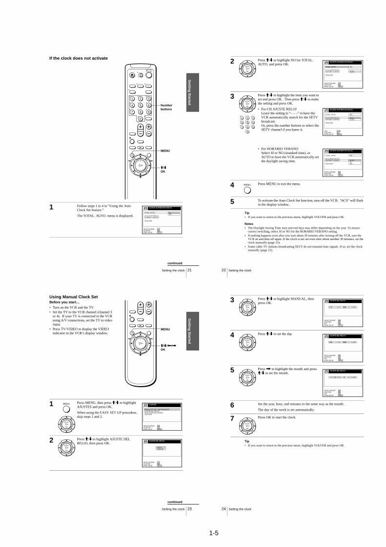
Setting the clockUsing the Auto Clock Set featureSony Entertainment Television (SETV) transmits time signals with its broadcasts. If the cable TV station in your area broadcasts SETV and transmits these time signals, your VCR can pick up these time signals to automatically set the clock.
The Auto Clock Set feature works only if SETV in your area broadcasts time signals. If SETV in your area does not broadcast time signals or if you select Hookup 1 on page 10 set the time manually (page 23).
Before you start…• Turn on the VCR and the TV.• Set the TV to the VCR channel (channel 3
or 4). If your TV is connected to the VCR using A/V connections, set the TV to video input.
• Press TV/VIDEO to display the VIDEO indicator in the VCR’s display window.
1 Press MENU, then press M/m to highlight AJUSTES and press OK.
When using the EASY SET UP procedure, skip steps 1 and 2.
2 Press M/m to highlight AJUSTE DEL RELOJ, then press OK.
M/mOK
MENU
OK
PLAY
MENU AJUSTES
PREAJUSTE DEL SINTONIZADORAJUSTE DEL RELOJSELECCION DEL IDIOMA
VOLVER
AJUSTAR :SELECCIONAR :
OKMENUPARA SALIR :
OK
PLAYAUTOMANUAL
AJUSTE DEL RELOJ
AJUSTAR :SELECCIONAR :
OKMENUPARA SALIR :
continued
20 Setting the clock
Tip• If you want to return to the previous menu, highlight VOLVER and press OK.
Notes• The clock cannot be set automatically if you don’t receive SETV broadcast that carries time
signals in your area. If so, set the clock manually (page 23).• Depending on the channels allotted to SETV in your area, setting the clock automatically
may take up to about 30 minutes. If nothing happens even after you wait about 30 minutes after turning off the VCR, turn the VCR on and then off again. If the clock is not set even after about another 30 minutes, set the clock manually (page 23).
• If the clock is not set, “ACS” will flash in the display window whenever the VCR is turned off. During this time, the VCR will search for a time signal.
3 Press M/m to highlight AUTO, then press OK.
4 Press M/m to highlight TOTAL. AUTO., then press OK.
5 Press M/m to highlight SI, then press OK.
6 Press MENU to exit the menu.
7 To activate the Auto Clock Set function, turn off the VCR. “ACS” will flash in the display window.
The VCR automatically sets the clock by searching for the SETV broadcast that carries time signals and sets Daylight Saving Time (if applicable).
If your clock is incorrectly set to Daylight Saving Time, you can adjust these settings without turning off the Auto Clock Set feature (page 21).
OK
PLAY
AJUSTE AUTOMATICO RELOJ
TOTAL. AUTO.
HORARIO VERANOCH AJUSTE RELOJ
VOLVER
SI
AJUSTAR :SELECCIONAR :
OKMENUPARA SALIR :
OK
PLAY
AJUSTE AUTOMATICO RELOJ
TOTAL. AUTO.
CH AJUSTE RELOJHORARIO VERANO
VOLVER
SINO
AJUSTAR :SELECCIONAR :
OKMENUPARA SALIR :
OK
PLAY
MENU
1-5
Gettin
g S
tarted
21Setting the clock
If the clock does not activate
1 Follow steps 1 to 4 in “Using the Auto Clock Set feature.”
The TOTAL. AUTO. menu is displayed.
1 2 3
4 5 6
7 8 9
0
MENU
Number buttons
M/mOK
AJUSTE AUTOMATICO RELOJ
TOTAL. AUTO.
CH AJUSTE RELOJHORARIO VERANO
VOLVER
SINO
AJUSTAR :SELECCIONAR :
OKMENUPARA SALIR :
continued
22 Setting the clock
Tip• If you want to return to the previous menu, highlight VOLVER and press OK.
Notes• The Daylight Saving Time start and end days may differ depending on the year. To ensure
correct switching, select SI or NO for the HORARIO VERANO setting.• If nothing happens even after you wait about 30 minutes after turning off the VCR, turn the
VCR on and then off again. If the clock is not set even after about another 30 minutes, set the clock manually (page 23).
• Some cable TV stations broadcasting SETV do not transmit time signals. If so, set the clock manually (page 23).
2 Press M/m to highlight NO for TOTAL. AUTO. and press OK.
3 Press M/m to highlight the item you want to set and press OK. Then press M/m to make the setting and press OK.
• For CH AJUSTE RELOJLeave the setting to “– – –” to have the VCR automatically search for the SETV broadcast.Or, press the number buttons to select the SETV channel if you know it.
• For HORARIO VERANOSelect SI or NO (standard time), or AUTO to have the VCR automatically set the daylight saving time.
4 Press MENU to exit the menu.
5 To activate the Auto Clock Set function, turn off the VCR. “ACS” will flash in the display window.
OK
PLAY
AJUSTE AUTOMATICO RELOJ
TOTAL. AUTO.
CH AJUSTE RELOJHORARIO VERANO
VOLVER
NO
– – –AUTO
AJUSTAR :SELECCIONAR :
OKMENUPARA SALIR :
OK
PLAY
1 2 3
4 5 6
7 8 9
0
AJUSTE AUTOMATICO RELOJ
TOTAL. AUTO.
CH AJUSTE RELOJHORARIO VERANO
VOLVER
AJUSTAR :USE :
OKMENUPARA SALIR :
NO
1 2 3AUTO
0–9
AJUSTE AUTOMATICO RELOJ
TOTAL. AUTO.
CH AJUSTE RELOJHORARIO VERANO
VOLVER
NO
AUTOSINO
AJUSTAR :SELECCIONAR :
OKMENUPARA SALIR :
MENU
Gettin
g S
tarted
23Setting the clock
Using Manual Clock SetBefore you start…
• Turn on the VCR and the TV.• Set the TV to the VCR channel (channel 3
or 4). If your TV is connected to the VCR using A/V connections, set the TV to video input.
• Press TV/VIDEO to display the VIDEO indicator in the VCR’s display window.
1 Press MENU, then press M/m to highlight AJUSTES and press OK.
When using the EASY SET UP procedure, skip steps 1 and 2.
2 Press M/m to highlight AJUSTE DEL RELOJ, then press OK.
MENU
M/m/</,OK
OK
PLAY
MENU AJUSTES
PREAJUSTE DEL SINTONIZADORAJUSTE DEL RELOJSELECCION DEL IDIOMA
VOLVER
AJUSTAR :SELECCIONAR :
OKMENUPARA SALIR :
OK
PLAYAUTOMANUAL
AJUSTE DEL RELOJ
AJUSTAR :SELECCIONAR :
OKMENUPARA SALIR :
continued
24 Setting the clock
Tip• If you want to return to the previous menu, highlight VOLVER and press OK.
3 Press M/m to highlight MANUAL, then press OK.
4 Press M/m to set the day.
5 Press , to highlight the month and press M/m to set the month.
6 Set the year, hour, and minutes in the same way as the month.
The day of the week is set automatically.
7 Press OK to start the clock.
OK
PLAY
FIN :AJUSTAR :
OKMENU
SELECCIONAR :
LUN 1 AM00:211 002/1/
AJUSTE DEL RELOJ
PARA SALIR :
OK
PLAYDOM 1 AM00:2182 002/1/
AJUSTE DEL RELOJ
FIN :AJUSTAR :
OKMENU
SELECCIONAR :
PARA SALIR :
OK
PLAYVIE 1 AM00:2182 002/9/
AJUSTE DEL RELOJ
FIN :AJUSTAR :
OKMENU
SELECCIONAR :
PARA SALIR :
OK
PLAY
1-6
Gettin
g S
tarted
25Presetting channels
Presetting channels
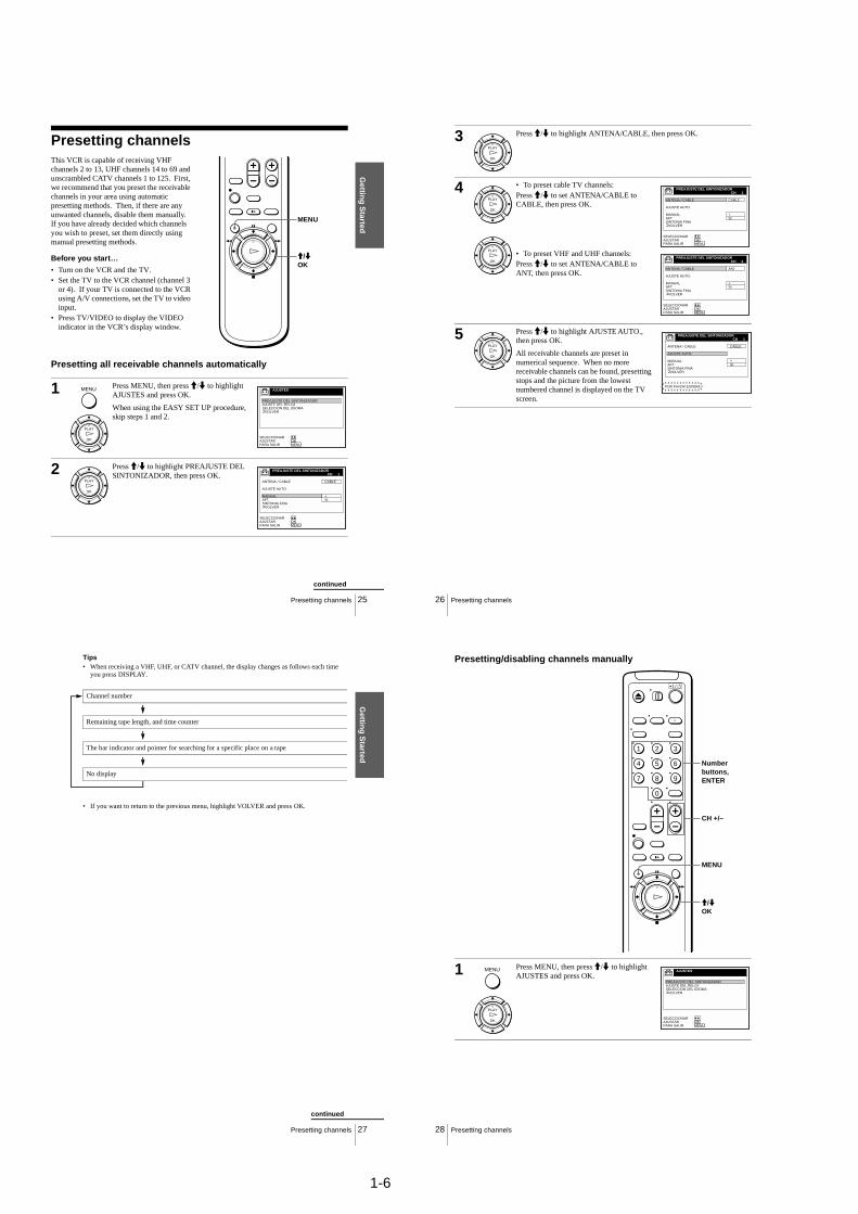
Presetting all receivable channels automatically
This VCR is capable of receiving VHF channels 2 to 13, UHF channels 14 to 69 and unscrambled CATV channels 1 to 125. First, we recommend that you preset the receivable channels in your area using automatic presetting methods. Then, if there are any unwanted channels, disable them manually. If you have already decided which channels you wish to preset, set them directly using manual presetting methods.
Before you start…• Turn on the VCR and the TV.• Set the TV to the VCR channel (channel 3
or 4). If your TV is connected to the VCR using A/V connections, set the TV to video input.
• Press TV/VIDEO to display the VIDEO indicator in the VCR’s display window.
1 Press MENU, then press M/m to highlight AJUSTES and press OK.
When using the EASY SET UP procedure, skip steps 1 and 2.
2 Press M/m to highlight PREAJUSTE DEL SINTONIZADOR, then press OK.
MENU
M/mOK
OK
PLAY
MENU AJUSTES
PREAJUSTE DEL SINTONIZADORAJUSTE DEL RELOJSELECCION DEL IDIOMA
VOLVER
AJUSTAR :SELECCIONAR :
OKMENUPARA SALIR :
OK
PLAY
PREAJUSTE DEL SINTONIZADOR
CABLE
+SI
ANTENA / CABLE
AJUSTE AUTO.
MANUALAFTSINTONIA FINA
VOLVER
AJUSTAR :SELECCIONAR :
OKMENUPARA SALIR :
CH 1
continued
26 Presetting channels
3 Press M/m to highlight ANTENA/CABLE, then press OK.
4 • To preset cable TV channels:Press M/m to set ANTENA/CABLE to CABLE, then press OK.
• To preset VHF and UHF channels:Press M/m to set ANTENA/CABLE to ANT, then press OK.
5 Press M/m to highlight AJUSTE AUTO., then press OK.
All receivable channels are preset in numerical sequence. When no more receivable channels can be found, presetting stops and the picture from the lowest numbered channel is displayed on the TV screen.
OK
PLAY
OK
PLAY
OK
PLAY
PREAJUSTE DEL SINTONIZADOR
CABLE
+SI
ANTENA / CABLE
AJUSTE AUTO.
MANUALAFTSINTONIA FINA
VOLVER
AJUSTAR :SELECCIONAR :
OKMENUPARA SALIR :
CH 1
PREAJUSTE DEL SINTONIZADOR
ANT
+SI
ANTENA / CABLE
AJUSTE AUTO.
MANUALAFTSINTONIA FINA
VOLVER
AJUSTAR :SELECCIONAR :
OKMENUPARA SALIR :
CH 2
OK
PLAY
PREAJUSTE DEL SINTONIZADOR
CABLE
+SI
ANTENA / CABLE
AJUSTE AUTO.
MANUALAFTSINTONIA FINA
VOLVER
CH 1
POR FAVOR ESPERE
Gettin
g S
tarted
27Presetting channels
Tips• When receiving a VHF, UHF, or CATV channel, the display changes as follows each time
you press DISPLAY.
• If you want to return to the previous menu, highlight VOLVER and press OK.
Channel number
Remaining tape length, and time counter
The bar indicator and pointer for searching for a specific place on a tape
No display
continued
28 Presetting channels
Presetting/disabling channels manually
1 Press MENU, then press M/m to highlight AJUSTES and press OK.
1 2 3
4 5 6
7 8 9
0
MENU
CH +/–
Number buttons, ENTER
M/mOK
OK
PLAY
MENU AJUSTES
PREAJUSTE DEL SINTONIZADORAJUSTE DEL RELOJSELECCION DEL IDIOMA
VOLVER
AJUSTAR :SELECCIONAR :
OKMENUPARA SALIR :

1-7
Gettin
g S
tarted
29Presetting channels
Tip• If you want to return to the previous menu, highlight VOLVER and press OK.
2 Press M/m to highlight PREAJUSTE DEL SINTONIZADOR, then press OK.
3 • To preset a channel:
1 Press the number buttons to enter the channel number, then press ENTER.
2 Press OK.3 Press M/m to set MANUAL to +, then
press OK.
• To disable a channel:
1 Press CH +/– to select the channel number.
2 Press OK.3 Press M/m to set MANUAL to –, then
press OK.
4 Repeat step 3 to preset or disable channels as required, then press MENU.
OK
PLAY
PREAJUSTE DEL SINTONIZADOR
CABLE
+SI
ANTENA / CABLE
AJUSTE AUTO.
MANUALAFTSINTONIA FINA
VOLVER
AJUSTAR :SELECCIONAR :
OKMENUPARA SALIR :
CH 1
OK
PLAY
OK
PLAY
1 2 3
4 5 6
7 8 9
0
• CH
PREAJUSTE DEL SINTONIZADOR
CABLE
+SI
ANTENA / CABLE
AJUSTE AUTO.
MANUALAFTSINTONIA FINA
VOLVER
CH 5
AJUSTAR :SELECCIONAR :
OKMENUPARA SALIR :
Channel to be preset
PREAJUSTE DEL SINTONIZADOR
CABLE
–SI
ANTENA / CABLE
AJUSTE AUTO.
MANUALAFTSINTONIA FINA
VOLVER
CH 5
AJUSTAR :SELECCIONAR :
OKMENUPARA SALIR :
Channel to be disabled
MENU
continued
30 Presetting channels
If the picture is not clearNormally, the Auto Fine Tuning (AFT) function automatically tunes in channels clearly. If, however, the picture of a channel is not clear, you can also use the manual tuning function.
1 Press MENU, then press M/m to highlight AJUSTES and press OK.
1 2 3
4 5 6
7 8 9
0
MENU
M/m/</,OK
Number buttons, ENTER
OK
PLAY
MENU AJUSTES
PREAJUSTE DEL SINTONIZADORAJUSTE DEL RELOJSELECCION DEL IDIOMA
VOLVER
AJUSTAR :SELECCIONAR :
OKMENUPARA SALIR :
Gettin
g S
tarted
31Presetting channels
Tips• To select the channel in step 3 above, you can also use the CH +/– buttons. In this case, you
don’t need to press ENTER.• If you want to return to the previous menu, highlight VOLVER and press OK.
Note• When adjusting SINTONIA FINA, the menu may become difficult to read due to interference
from the picture being received.
2 Press M/m to highlight PREAJUSTE DEL SINTONIZADOR, then press OK.
3 Press the number buttons to select the channel you want to fine-tune, then press ENTER.
4 Press M/m to highlight SINTONIA FINA, then press OK.
The fine tuning meter appears.
5 Press </, to adjust to a clearer picture, then press OK.
Note that the AFT setting switches to NO.
6 Press MENU to exit the menu.
OK
PLAY
PREAJUSTE DEL SINTONIZADOR
CABLE
+SI
ANTENA / CABLE
AJUSTE AUTO.
MANUALAFTSINTONIA FINA
VOLVER
AJUSTAR :SELECCIONAR :
OKMENUPARA SALIR :
CH 1
1 2 3
4 5 6
7 8 9
0
PREAJUSTE DEL SINTONIZADOR
CABLE
+SI
ANTENA / CABLE
AJUSTE AUTO.
MANUALAFTSINTONIA FINA
VOLVER
CH 5
AJUSTAR :SELECCIONAR :
OKMENUPARA SALIR :
Selected channel
OK
PLAY
PREAJUSTE DEL SINTONIZADOR
CABLE
+
ANTENA / CABLE
AJUSTE AUTO.
MANUALAFTSINTONIA FINA
VOLVER
AJUSTAR :SELECCIONAR :
OKMENUPARA SALIR :
CH 5
OK
PLAY
PREAJUSTE DEL SINTONIZADOR
CABLE
+NO
ANTENA / CABLE
AJUSTE AUTO.
MANUALAFTSINTONIA FINA
VOLVER
CH 5
AJUSTAR :SELECCIONAR :
OKMENUPARA SALIR :
MENU
32 Playing a tape
Basic Operations
Playing a tape
1 Turn on your TV and set it to the video channel.
2 Insert a tape.
The VCR turns on and starts playing automatically if you insert a tape with its safety tab removed.
1 2 3
4 5 6
7 8 9
0
Z EJECT
DISPLAY
CLEAR
H PLAY
REPLAYX PAUSE
M FF
x STOP
m REW
TRINITRON TV SYNCHRO PLAY
1-8
33Playing a tape
Basic O
peratio
ns
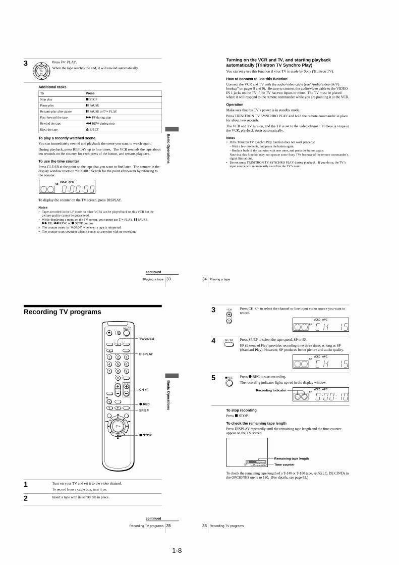
Additional tasks
To play a recently watched sceneYou can immediately rewind and playback the scene you want to watch again.
During playback, press REPLAY up to four times. The VCR rewinds the tape about ten seconds on the counter for each press of the button, and restarts playback.
To use the time counterPress CLEAR at the point on the tape that you want to find later. The counter in the display window resets to “0:00:00.” Search for the point afterwards by referring to the counter.
To display the counter on the TV screen, press DISPLAY.
Notes• Tapes recorded in the LP mode on other VCRs can be played back on this VCR but the
picture quality cannot be guaranteed.• While displaying a menu on the TV screen, you cannot use H PLAY, X PAUSE,M FF, m REW, or x STOP buttons.
• The counter resets to “0:00:00” whenever a tape is reinserted.• The counter stops counting when it comes to a portion with no recording.
3 Press H PLAY.
When the tape reaches the end, it will rewind automatically.
To Press
Stop play x STOP
Pause play X PAUSE
Resume play after pause X PAUSE or H PLAY
Fast-forward the tape M FF during stop
Rewind the tape m REW during stop
Eject the tape Z EJECT
OK
PLAY
SPVIDEO APC
continued
34 Playing a tape
Turning on the VCR and TV, and starting playback automatically (Trinitron TV Synchro Play)You can only use this function if your TV is made by Sony (Trinitron TV).
How to connect to use this function
Connect the VCR and TV with the audio/video cable (see “Audio/video (A/V) hookup” on pages 8 and 9). Be sure to connect the audio/video cable to the VIDEO IN 1 jacks on the TV if the TV has two inputs or more. The TV must be placed where it will respond to the remote commander while you are pointing it at the VCR.
Operation
Make sure that the TV’s power is in standby mode.
Press TRINITRON TV SYNCHRO PLAY and hold the remote commander in place for about two seconds.
The VCR and TV turn on, and the TV is set to the video channel. If there is a tape in the VCR, playback starts automatically.
Notes• If the Trinitron TV Synchro Play function does not work properly:
– Wait a few moments, and press the button again.– Replace both of the batteries with new ones, and press the button again. Note that this function may not operate some Sony TVs because of the remote commander’s signal limitations.
• Do not press TRINITRON TV SYNCHRO PLAY during playback. If you do so, the TV’s input source will momentarily switch to the TV’s tuner.
35Recording TV programs
Basic O
peratio
ns
Recording TV programs
1 Turn on your TV and set it to the video channel.
To record from a cable box, turn it on.
2 Insert a tape with its safety tab in place.
1 2 3
4 5 6
7 8 9
0
CH +/–
z REC
x STOP
DISPLAY
TV/VIDEO
SP/EP
continued
36 Recording TV programs
To stop recordingPress x STOP.
To check the remaining tape lengthPress DISPLAY repeatedly until the remaining tape length and the time counter appear on the TV screen.
To check the remaining tape length of a T-140 or T-180 tape, set SELC. DE CINTA in the OPCIONES menu to 180. (For details, see page 63.)
3 Press CH +/– to select the channel or line input video source you want to record.
4 Press SP/EP to select the tape speed, SP or EP.
EP (Extended Play) provides recording time three times as long as SP (Standard Play). However, SP produces better picture and audio quality.
5 Press z REC to start recording.
The recording indicator lights up red in the display window.
• CH
EP
VIDEO APC
SP / EP
SPVIDEO APC
REC
SPVIDEO APCRecording indicator
SP 20 : 0 0 : 2 Time counter
Remaining tape length

1-9
37Recording TV programs
Basic O
peratio
ns
To watch another TV program while recording
To save a recordingTo prevent accidental erasure, break off the safety tab as illustrated. To record on the tape again, cover the tab hole with adhesive tape.
Tips• To select a channel, you can use the number buttons on the remote commander. Enter the
channel number, then press ENTER.• You can select a video source from the LINE-1 IN or LINE-2 IN jacks using the INPUT
SELECT button.• The display appears on the TV screen indicating information about the tape, but the
information won’t be recorded on the tape.• If you don’t want to watch TV while recording, you can turn off the TV. When using a cable
box, make sure to leave it on.
Notes• The remaining tape length may not be indicated accurately for short tapes such as T-20 or T-
30, or tapes recorded in the LP mode.• The display does not appear during still (pause) mode or slow-motion playback.• It may take up to one minute for the VCR to calculate and display the remaining tape length
after you press DISPLAY.
1 Press TV/VIDEO to turn off the VIDEO indicator in the display window.
2 If the TV is connected to the VCR’s LINE OUT jacks, set the TV to the TV’s antenna input; if not, skip this step.
3 Select another channel on the TV.
Safety tab
38 Recording TV programs using the Dial Timer
Recording TV programs using the Dial TimerThe Dial Timer function allows you to make timer recordings of programs without turning on your TV. Set the recording timer to record up to eight programs that will be broadcast within a month using the DIAL TIMER. The recording start time and recording stop time can be set at one minute intervals.
Before you start...• When using a cable box, turn it on.• Insert a tape with its safety tab in place. Make sure the tape is longer than the total recording
time.
1 Press DIAL TIMER.
“DIA” and “HOY” appear alternately in the display window.
If the date and time are not set, “DIA” flashes. See step 2 in the following section “To set the clock” to set the date and time.
2 Turn DIAL TIMER to set the recording date.
CHANNEL +/–?/1 POWER
DIAL TIMERINPUT SELECT x STOP
DIAL TIMER
EP
VIDEO APC
EP
VIDEO APC
DIAL TIMER
EP
VIDEO APC
39Recording TV programs using the Dial Timer
Basic O
peratio
ns
3 Press DIAL TIMER.
“DESDE” and the current time appear alternately in the display window.
4 Turn DIAL TIMER to set the recording start time.
You can set the recording start time in 15 minute intervals or adjust the time in one minute intervals by pressing the CHANNEL +/– buttons.
5 Press DIAL TIMER.
“HASTA” and the recording stop time appear alternately in the display window.
6 Turn DIAL TIMER to set the recording stop time.
You can set the recording stop time in 15 minute intervals or adjust the time in one minute intervals by pressing the CHANNEL +/– buttons.
DIAL TIMER
EP
VIDEO APC
EP
VIDEO APC
DIAL TIMER
CHANNELEP
VIDEO APC
DIAL TIMER
EP
VIDEO APC
EP
VIDEO APC
DIAL TIMER
CHANNELEP
VIDEO APC
continued
40 Recording TV programs using the Dial Timer
To return to the previous stepTo return to the previous step, press the CHANNEL + and – buttons on the VCR at the same time during any of the Dial Timer settings.
To stop recordingTo stop the VCR while recording, press x STOP.
To use the VCR after setting the timer
To use the VCR before a timer recording begins, just press ?/1. The indicator disappears from the display window and the VCR switches on. Remember to press?/1 to reset the VCR to the timer recording standby mode after using the VCR.
You can also do the following tasks while the VCR is recording:
• Reset the counter (page 33).• Display tape information on the TV screen (page 36).• Check the timer settings (page 51).• Watch another TV program (page 37).
7 Press DIAL TIMER.
The channel number appears in the display window.
8 Turn DIAL TIMER to set the channel number.
To record from a source connected to the LINE-1 IN or LINE-2 IN jacks, turn DIAL TIMER or press INPUT SELECT to display “L1” or “L2”.
9 Press DIAL TIMER to complete the setting.
“OK” appears in the display window for about five seconds.
The indicator appears in the display window and the VCR stands by for recording. When using a cable box, leave it on.
DIAL TIMER
EP
VIDEO APC
DIAL TIMER
INPUTSELECT
EP
VIDEO APC
DIAL TIMER
1-10
41Recording TV programs using the Dial Timer
Basic O
peratio
ns
To set the clock
Tips• To cancel a Dial Timer setting, press x STOP on the VCR while you are making the setting.• The program is recorded in the current tape speed. To change the tape speed, press SP/EP
before you complete the setting in step 9 (page 40).• When you are recording a program in the SP mode and the remaining tape becomes shorter
than the recording time, the tape speed is automatically changed to the EP mode. Note that some noise will appear on the picture when the tape speed is changed. If you want to keep the tape speed, set VEL. AUTO. CINTA to NO in the OPCIONES menu (page 63).
• To check, change, or cancel the program setting, see “Checking/changing/canceling timer settings” (page 51).
Notes• If eight programs have already been set using the PROG./VERIF. menu, “LLENO” appears
in the display window for about five seconds.• If you set the clock using the Auto Clock Set function, the clock will adjust itself to the
incoming time signal regardless of adjustments made with the Dial Timer. Be sure you have set ACS correctly.
• The indicator flashes in the display window when you complete the setting in step 9 (page 40) with no tape inserted.
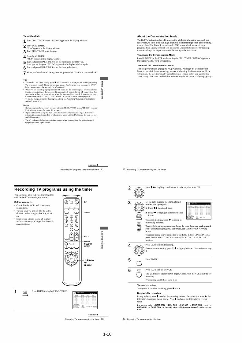
1 Turn DIAL TIMER so that “RELOJ” appears in the display window.
2 Press DIAL TIMER. “DIA” appears in the display window.
3 Turn DIAL TIMER to set the day.
4 Press DIAL TIMER. “MES” appears in the display window.
5 Turn and press DIAL TIMER to set the month and then the year.After you set the year, “RELOJ” appears in the display window again.
6 Turn and press DIAL TIMER to set the hour and minute.
7 When you have finished setting the time, press DIAL TIMER to start the clock.
continued
42 Recording TV programs using the Dial Timer
About the Demonstration ModeThe Dial Timer function has a Demonstration Mode that allows the user, such as a salesperson, to enter more than eight examples of timer settings when demonstrating the use of the Dial Timer. It cancels the LLENO notice which appears if eight programs have already been set. Do not use the Demonstration Mode for making timer recordings. Doing so may cause the settings to be inaccurate.
To activate the Demonstration ModePress X PAUSE on the VCR while turning the DIAL TIMER. “DEMO” appears in the display window for a few seconds.
To cancel the Demonstration ModeTurn the power off and unplug the AC power cord. Although the Demonstration Mode is canceled, the timer settings entered while using the Demonstration Mode will remain. Be sure to manually cancel the timer settings before you use the Dial Timer or any other timer method after reconnecting the AC power cord (see page 51).
43Recording TV programs using the timer
Basic O
peratio
ns
Recording TV programs using the timerYou can preset up to eight programs together with the Dial Timer settings at a time.
Before you start…• Check that the VCR clock is set to the
correct time.• Turn on your TV and set it to the video
channel. When using a cable box, turn it on.
• Insert a tape with its safety tab in place. Make sure the tape is longer than the total recording time.
1 Press TIMER to display PROG./VERIF.
1 2 3
4 5 6
7 8 9
0
INPUT SELECTSP/EP
TIMER
CH +/–
M/m/</,OKx STOP
?/1
TIMERVIE
– – – ––: – –– –– – –:– /– –– /– –– /– –– /– –– /– –– /– –– /– –– /
– ––: – –– –– – ––
:– ––: – –– –– –:
– ––: – –– –– – –:– ––: – –– –– – –:– ––: – –– –– – –:– ––: – –– –– – –:– ––: – –– –– – –:
PROG. / VERIF.
CH
VOLVER
MENUPARA SALIR :AJUSTAR :SELECCIONAR :
OK
FECHA TER.COM.
CANCELAR : CLEAR
9/2 8
continued
44 Recording TV programs using the timer
To stop recordingTo stop the VCR while recording, press x STOP.
Daily/weekly recordingIn step 3 above, press m to select the recording pattern. Each time you press m, the indication changes as shown below. Press M to change the indication in reverse order.
the current date t DOM-SAB t LUN-SAB t LUN-VIE t CADA SAB t ..... t CADA LUN t CADA DOM t 1 month later t (dates count down) t the current date
2 Press M/m to highlight the line that is to be set, then press OK.
3 Set the date, start and stop time, channel number, and tape speed:
1 Press M/m to set each item.
2 Press , to highlight and set each item in turn.
To correct a setting, press < to return to that setting and reset.
To record the same program every day or the same day every week, press m while the date is highlighted. For details, see “Daily/weekly recording” below.
To record from a source connected to the LINE-1 IN or LINE-2 IN jacks, press INPUT SELECT or CH+/– to display “L1” or “L2” in the “CH” position.
4 Press OK to confirm the setting.
To enter another setting, press M/m to highlight the next line and repeat step 3.
5 Press TIMER.
6 Press ?/1 to turn off the VCR.
The indicator appears in the display window and the VCR stands by for recording.
When using a cable box, leave it on.
OK
PLAY
OK
PLAY
INPUTSELECT
• CH
VIE
DOM 8 0 PM PM0: 9 00 53 SP:
– ––: – –– –– – –:– ––: – –– –– – –:
– ––: – –– –– – –:– ––: – –– –– – –:– ––: – –– –– – –:– ––: – –– –– – –:– ––: – –– –– – –:
3 90 /– –– /– –– /– –– /– –– /– –– /– –– /– –– /
MENUFIN : OK
PROG. / VERIF.
CH
VOLVER
PARA SALIR :AJUSTAR :SELECCIONAR :
9/2 8
FECHA TER.COM.
OK
PLAY
TIMER

1-11
45Recording TV programs using the timer
Basic O
peratio
ns
To use the VCR after setting the timer
To use the VCR before timer recording begins, just press ?/1. The indicator disappears from the display window and the VCR switches on. Remember to press?/1 to reset the VCR to the timer recording standby mode after using the VCR.
You can also do the following tasks while the VCR is recording:
• Reset the counter (page 33).• Display tape information on the TV screen. (page 36).• Check the timer settings (page 51).• Watch another TV program (page 37).
Tips• To set the channel, you can also use the CH+/– or number buttons.• To show the PROG./VERIF. menu, you can also use the MENU button. Press MENU, then
press M/m to highlight PROG./VERIF. and press OK.• To set the tape speed, you can also use the SP/EP button.• When you are recording a program in the SP mode and the remaining tape becomes shorter
than the recording time, the tape speed is automatically changed to the EP mode. Note that some noise will appear on the picture when the tape speed is changed. If you want to keep the tape speed, set VEL. AUTO. CINTA to NO in the OPCIONES menu (page 63).
• To check, change or cancel the program setting, see “Checking/changing/canceling timer settings” (page 51).
• If you want to return to the previous menu and continue with other operations after setting the timer, press m to highlight VOLVER, then press OK.The display returns to the MENU screen.If you are finished using the VCR, turn off the power before timer recording starts.
46 Playing/searching at various speeds
Additional Operations
Playing/searching at various speeds
To resume normal playbackPress H PLAY.
Playback options Operation
View the picture during fast-forward or rewind
During fast-forward, hold down M FF. During rewind, hold down m REW.
Play at high speed • During playback, briefly press M FF or m REW on the remote commander. The tape continues to play at high speed.
• During playback, hold down M FF or m REW. When you release the button, normal playback resumes.
Play at twice the normal speed During playback, press ×2.
Play in slow motion During playback or pause, press y SLOW.
Play frame by frame During pause, press M FF or m REW on the remote commander. Hold down the button to play one frame each second.
Rewind and start play While the tape is stopped, hold down m REW on the VCR and press H PLAY on the VCR.
0
y SLOW
x2
M FF
m REW
H PLAY
m REW M FF
TRACKING +/–
47Playing/searching at various speeds
Ad
ditio
nal O
peratio
ns
Tip• Adjust the picture using the TRACKING +/– buttons if:
– Streaks appear while playing in slow motion.– The picture shakes during pause.To set tracking to the center position, press both buttons (+/–) at the same time.
Notes• The sound is muted during these operations.• Tapes recorded in the LP mode on other VCRs can be played back on this VCR but the
picture quality cannot be guaranteed.• The picture may show noise when playing at high speed in reverse.
48 Setting the recording duration time
Setting the recording duration time
To extend the durationPress z REC repeatedly to set a new duration time.
To cancel the duration
Press z REC repeatedly until the indicator disappears and the VCR returns to normal recording mode.
To stop while recordingPress x STOP.
Note• You cannot display the current tape time in the display window when setting the recording
duration time.
After you have started recording, you can have the VCR stop recording automatically after a specified duration.
1 While recording, press z REC.
The indicator appears in the display window.
2 Press z REC repeatedly to set the duration time.
Each press advances the time in increments of 30 minutes.
The tape counter decreases minute by minute to 0:00, then the VCR stops recording and turns off automatically.
z REC
SPVIDEO APC
0:30 1:00 5:30 6:00 Normal recording

1-12
49Synchronized Recording
Ad
ditio
nal O
peratio
ns
Synchronized RecordingYou can set the VCR to automatically record programs from equipment such as a satellite tuner or cable TV decoder by connecting the equipment to the LINE-1 IN jacks. The connected equipment must have a timer function for this feature to work.
When the connected equipment turns on, the VCR also automatically turns on and starts recording a program from the LINE-1 IN jacks.
How to connect for Synchronized RecordingConnect the other equipment to the LINE-1 IN jacks of this VCR.
Recording programs using the Synchronized Recording function
Before you start...• Insert a tape with its safety tab in place.
Make sure the tape is longer than the total recording time.
This VCR (Recorder)
LINE-1 IN
Satellite tuner, etc.
LINE OUT
Audio/video cable (not supplied)
: Signal flow
SYNCHRO REC
CH +/–
SP/EP
INPUT SELECT
continued
50 Synchronized Recording
To cancel the Synchronized Recording functionPress SYNCHRO REC. The SYNCHRO REC button turns off.
To stop recordingPress x STOP while recording.
The VCR automatically stops recording when the tape reaches the end or when the other equipment stops transmitting the video signals.
Notes• Some equipment keeps transmitting signals even though the power is off. In this case, the
Synchronized Recording feature does not work because the VCR will not be able to know when to start recording. To record the program, set the timer on the VCR. For details, see “Recording TV programs using the timer.” If you use a satellite tuner or a cable TV decoder, make sure to set their timers as well.
• Some TVs or other equipment with timer functions will automatically turn off if no operation is performed within a certain amount of time. In this case, the Synchronized Recording also stops automatically.
• When the connected equipment turns on while the SYNCHRO REC button is lit, recording starts automatically.
• If the settings for timer recording and Synchronized Recording overlap, the program that starts first has priority and the second program starts recording only after the first program has finished.
• The Auto Clock Set function does not work while the VCR stands by for Synchronized Recording.
1 Press INPUT SELECT or CH +/– to display “L1” in the display window.
2 Set the timer on the connected equipment to the time of the program you want to record, then turn it off.
3 Press SP/EP to select the tape speed.
4 Hold down SYNCHRO REC for more than two seconds.
The SYNCHRO REC button lights up and the VCR stands by for recording.
The VCR automatically turns on and starts recording when it receives a video signal from the connected equipment.
51Checking/changing/canceling timer settings
Ad
ditio
nal O
peratio
ns
Checking/changing/canceling timer settingsBefore you start…• Turn on your TV and set it to the video
channel.
1 Press ?/1 to turn on the VCR.
2 Press TIMER to display PROG./VERIF.
• If you want to change a setting, go on to the next step.• If you do not need to change the settings, press MENU, then turn off the VCR
to return to recording standby.
1 2 3
4 5 6
7 8 9
0
?/1
MENU
M/m/</,OK
CLEAR
TIMER
continued
52 Checking/changing/canceling timer settings
When the timer settings overlapThe program that starts first has priority and the second program starts recording only after the first program has finished. If the programs start at the same time, the program listed first in the menu has priority.
Tip• To show the PROG./VERIF. menu, you can also use the MENU button. Press MENU, then
press M/m to highlight PROG./VERIF. and press OK.
3 Press M/m to highlight the setting you want to change or cancel.
• To change the setting, press OK and press </, to highlight the item you want to change, then press M/m to reset it.
• To cancel the setting, press CLEAR.
4 Press OK.
5 Press MENU to exit the menu.
If any timer settings remain, turn off the VCR to return to recording standby.
PROG. / VERIF.
CHDOM 8 0 PM PM0: 9 00 53 SP:/
–– – ––: – –– –– – –:–/–– – ––: – –– –– – –:–/
–– – ––: – –– –– – –:–/–– – ––: – –– –– – –:–/
CADA 6 03: 7 00 24 EP:LUN –
MERVIE 2 00: 3 00 06 EP:
2 01 0 1
AMPMAM
AMPMAM0: 1 03 02 EP:1 0 MAR/
VOLVER
MENUPARA SALIR :AJUSTAR :SELECCIONAR :
OK CANCELAR : CLEAR
03 9
9/2 8 VIE
FECHA TER.COM.
Will be cut off
Program 1
Program 2

1-13
53Recording stereo and bilingual programs
Ad
ditio
nal O
peratio
ns
Recording stereo and bilingual programsRecording stereo programsThis VCR automatically receives and records stereo programs. When a stereo program is received, the STEREO indicator lights up. If there is noise in the stereo program, set ESTEREO AUTO. in the OPCIONES menu to NO. The sound will be recorded in monaural (on both hi-fi and normal audio tracks) but with less noise. For details, see page 63.
Recording bilingual programsNormally, this VCR records only the main sound. When a SAP (Second Audio Program) is received, the SAP indicator lights up. To record only SAP sound, set SINTONIZ. AUDIO in the OPCIONES menu to SAP. For details, see page 63.
Selecting the sound during playbackPress AUDIO MONITOR to select the sound you want.
To listen to On-screen display Display window
Stereo ESTEREO STEREO
Left channel L STEREO
Right channel R STEREO
Monaural sound on the normal audio track
No indicator No indicator
continued
54 Recording stereo and bilingual programs
How sound is recorded on a video tapeThe VCR records sound onto two separate tracks. Hi-fi audio is recorded onto the main track along with the picture. Monaural sound is recorded onto the normal audio track along the edge of the tape.
Notes• To play a tape in stereo, you must use the A/V connections.• When you play a tape recorded in monaural, the sound is heard in monaural regardless of the
AUDIO MONITOR setting.
Normal audio track
Hi-fi audio track(main track)
Monaural sound
Stereo sound(left/right channels)
55Searching for the beginning of a timer recorded program
Ad
ditio
nal O
peratio
ns
Searching for the beginning of a timer recorded program
Press DIAL TIMER.
The VCR turns on, rewinds to the beginning of the most recently recorded program and starts playback automatically. The SEARCH MODE button turns off.
Tip• To turn off the SEARCH MODE button, first turn the VCR on, then press the
SEARCH MODE button. (Do not press any other button at this point, otherwise this SEARCH MODE function will be canceled.) To start the SEARCH MODE function, press the SEARCH MODE button once. If you press the SEARCH MODE button repeatedly, you can enter the index search or Time Search mode (for details, see page 56 and 57).
Notes• This SEARCH MODE function will be canceled (the SEARCH MODE button
turns off) if:– The VCR starts recording other programs.– You press H PLAY, M FF, m REW, or A EJECT button while the VCR is on.– If there is a power failure.
If you record a program using the timer function, you can easily find the beginning of the recording with this SEARCH MODE function. The SEARCH MODE button lights up when the VCR finishes a timer recording and the display window shows the following:
SEARCH MODE
DIAL TIMER
56 Searching using the index function
Searching using the index function
To stop searchingPress x STOP.
Note
• No index signal will be added when recording starts from recording pause. However, an index signal will be marked if you change the channel during recording pause.
The VCR marks the tape with an index signal at the point where each recording begins. Use these signals as references to find a specific recording. The VCR can search up to 9 index signals ahead of or behind the current position.
1 Press SEARCH MODE on the VCR repeatedly until “INDEX” appears in the display window (the SEARCH MODE button lights up).
2 Turn DIAL TIMER to specify how many index signals ahead or behind you want to search:
• To search ahead, turn DIAL TIMER clockwise.• To search backwards, turn DIAL TIMER counterclockwise.
3 Press DIAL TIMER.
The VCR starts searching. The playback starts (the SEARCH MODE button turns off) from the point about five seconds ahead of the specified index mark.
SEARCH MODE
DIAL TIMER
SPAPC
SPAPC
1-14
57Searching using the Time Search function
Ad
ditio
nal O
peratio
ns
Searching using the Time Search function
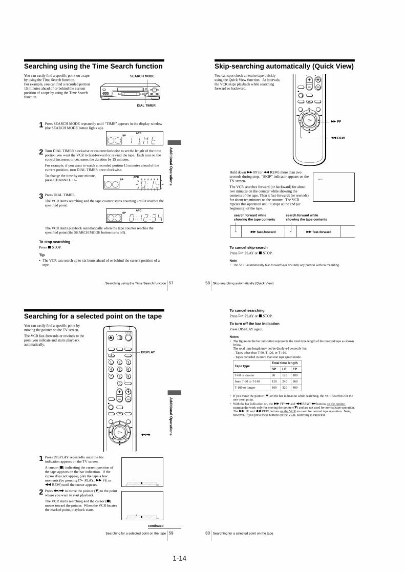
To stop searchingPress x STOP.
Tip• The VCR can search up to six hours ahead of or behind the current position of a
tape.
You can easily find a specific point on a tape by using the Time Search function.For example, you can find a recorded portion 15 minutes ahead of or behind the current position of a tape by using the Time Search function.
1 Press SEARCH MODE repeatedly until “TIME” appears in the display window (the SEARCH MODE button lights up).
2 Turn DIAL TIMER clockwise or counterclockwise to set the length of the time portion you want the VCR to fast-forward or rewind the tape. Each turn on the control increases or decreases the duration by 15 minutes.
For example, if you want to watch a recorded portion 15 minutes ahead of the current position, turn DIAL TIMER once clockwise.
To change the time by one minute, press CHANNEL +/–.
3 Press DIAL TIMER.
The VCR starts searching and the tape counter starts counting until it reaches the specified point.
The VCR starts playback automatically when the tape counter reaches the specified point (the SEARCH MODE button turns off).
SEARCH MODE
DIAL TIMER
SPAPC
SPAPC
SPAPC
58 Skip-searching automatically (Quick View)
Skip-searching automatically (Quick View)
Hold down M FF (or m REW) more than two seconds during stop. “SKIP” indicator appears on the TV screen.
The VCR searches forward (or backward) for about two minutes on the counter while showing the contents of the tape. Then it fast-forwards (or rewinds) for about ten minutes on the counter. The VCR repeats this operation until it stops at the end (or beginning) of the tape.
To cancel skip-searchPress H PLAY or x STOP.
Note• The VCR automatically fast-forwards (or rewinds) any portion with no recording.
You can spot check an entire tape quickly using the Quick View function. At intervals, the VCR skips playback while searching forward or backward.
M FF
m REW
S K I P
search forward while showing the tape contents
search forward while showing the tape contents
M fast-forward M fast-forward
59Searching for a selected point on the tape
Ad
ditio
nal O
peratio
ns
Searching for a selected point on the tapeYou can easily find a specific point by moving the pointer on the TV screen.
The VCR fast-forwards or rewinds to the point you indicate and starts playback automatically.
1 Press DISPLAY repeatedly until the bar indication appears on the TV screen.
A cursor (x) indicating the current position of the tape appears on the bar indication. If the cursor does not appear, play the tape a few moments (by pressing H PLAY, M FF, or m REW) until the cursor appears.
2 Press </, to move the pointer (V) to the point where you want to start playback.
The VCR starts searching and the cursor (x) moves toward the pointer. When the VCR locates the marked point, playback starts.
1 2 3
4 5 6
7 8 9
0
DISPLAY
</,
0 1 2 0
0 1 2 0
continued
60 Searching for a selected point on the tape
To cancel searchingPress H PLAY or x STOP.
To turn off the bar indicationPress DISPLAY again.
Notes• The figure on the bar indication represents the total time length of the inserted tape as shown
below.The total time length may not be displayed correctly for:– Tapes other than T-60, T-120, or T-160.– Tapes recorded in more than one tape speed mode.
• If you move the pointer (V) on the bar indication while searching, the VCR searches for the new reset point.
• With the bar indication on, the M FF/ , and m REW/ < buttons on the remote commander work only for moving the pointer (V) and are not used for normal tape operation.The M FF and m REW buttons on the VCR are used for normal tape operation. Note, however, if you press these buttons on the VCR, searching is canceled.
Tape typeTotal time length
SP LP EP
T-60 or shorter 60 120 180
from T-80 to T-140 120 240 360
T-160 or longer 160 320 480
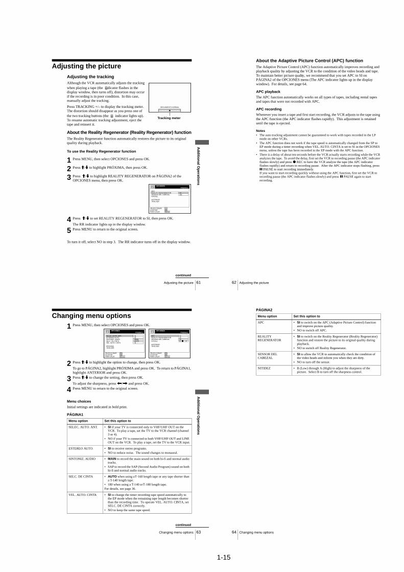
1-15
61Adjusting the picture
Ad
ditio
nal O
peratio
ns
Adjusting the pictureAdjusting the trackingAlthough the VCR automatically adjusts the tracking when playing a tape (the indicator flashes in the display window, then turns off), distortion may occur if the recording is in poor condition. In this case, manually adjust the tracking.
Press TRACKING +/– to display the tracking meter. The distortion should disappear as you press one of the two tracking buttons (the indicator lights up). To resume automatic tracking adjustment, eject the tape and reinsert it.
About the Reality Regenerator (Reality Regenerator) functionThe Reality Regenerator function automatically restores the picture to its original quality during playback.
To use the Reality Regenerator function
To turn it off, select NO in step 3. The RR indicator turns off in the display window.
1 Press MENU, then select OPCIONES and press OK.
2 Press M/m to highlight PRÓXIMA, then press OK.
3 Press M/m to highlight REALITY REGENERATOR on PÁGINA2 of the OPCIONES menu, then press OK.
4 Press M/m to set REALITY REGENERATOR to SI, then press OK.
The RR indicator lights up in the display window.
5 Press MENU to return to the original screen.
SEGUIMIENTO NORMAL
Tracking meter
OPCIONES
REALITY REGENERATORAPC
SENSOR DEL CABEZALNITIDEZ
NOSI
ANTERIORVOLVER
AJUSTAR :SELECCIONAR :
OKMENUPARA SALIR :
2PÁGINA
continued
62 Adjusting the picture
About the Adaptive Picture Control (APC) functionThe Adaptive Picture Control (APC) function automatically improves recording and playback quality by adjusting the VCR to the condition of the video heads and tape. To maintain better picture quality, we recommend that you set APC to SI on PÁGINA2 of the OPCIONES menu (The APC indicator lights up in the display window). For details, see page 64.
APC playbackThe APC function automatically works on all types of tapes, including rental tapes and tapes that were not recorded with APC.
APC recordingWhenever you insert a tape and first start recording, the VCR adjusts to the tape using the APC function (the APC indicator flashes rapidly). This adjustment is retained until the tape is ejected.
Notes• The auto tracking adjustment cannot be guaranteed to work with tapes recorded in the LP
mode on other VCRs.• The APC function does not work if the tape speed is automatically changed from the SP to
EP mode during a timer recording when VEL. AUTO. CINTA is set to SI in the OPCIONES menu, unless the tape has been recorded in the EP mode with the APC function.
• There is a delay of about ten seconds before the VCR actually starts recording while the VCR analyzes the tape. To avoid the delay, first set the VCR to recording pause (the APC indicator flashes slowly) and press z REC to have the VCR analyze the tape (the APC indicator flashes rapidly) and return to recording pause. After the APC indicator stops flashing, press X PAUSE to start recording immediately.If you want to start recording quickly without using the APC function, first set the VCR to recording pause (the APC indicator flashes slowly) and press X PAUSE again to start recording.
63Changing menu options
Ad
ditio
nal O
peratio
ns
Changing menu options
Menu choices
Initial settings are indicated in bold print.
PÁGINA1
1 Press MENU, then select OPCIONES and press OK.
2 Press M/m to highlight the option to change, then press OK.
To go to PÁGINA2, highlight PRÓXIMA and press OK. To return to PÁGINA1, highlight ANTERIOR and press OK.
3 Press M/m to change the setting, then press OK.
To adjust the sharpness, press </, and press OK.
4 Press MENU to return to the original screen.
Menu option Set this option to
SELEC. AUTO. ANT. • SI if your TV is connected only to VHF/UHF OUT on the VCR. To play a tape, set the TV to the VCR channel (channel 3 or 4).
• NO if your TV is connected to both VHF/UHF OUT and LINE OUT on the VCR. To play a tape, set the TV to the VCR input.
ESTEREO AUTO. • SI to receive stereo programs.• NO to reduce noise. The sound changes to monaural.
SINTONIZ. AUDIO • MAIN to record the main sound on both hi-fi and normal audio tracks.
• SAP to record the SAP (Second Audio Program) sound on both hi-fi and normal audio tracks.
SELC. DE CINTA • AUTO when using a T-160 length tape or any tape shorter than a T-140 length tape.
• 180 when using a T-140 or T-180 length tape.For details, see page 36.
VEL. AUTO. CINTA • SI to change the timer recording tape speed automatically to the EP mode when the remaining tape length becomes shorter than the recording time. To operate VEL. AUTO. CINTA, set SELC. DE CINTA correctly.
• NO to keep the same tape speed.
OPCIONES
ESTEREO AUTO.SELEC. AUTO. ANT.
SINTONIZ. AUDIOSELC. DE CINTA
SIMAIN
SI
AUTOVEL. AUTO. CINTA SI
PRÓXIMAVOLVER
AJUSTAR :SELECCIONAR :
OKMENUPARA SALIR :
1PÁGINAOPCIONES
REALITY REGENERATORAPC
SENSOR DEL CABEZALNITIDEZ
SISI
SI
ANTERIORVOLVER
AJUSTAR :SELECCIONAR :
OKMENUPARA SALIR :
2PÁGINA
B A
continued
64 Changing menu options
PÁGINA2
Menu option Set this option to
APC • SI to switch on the APC (Adaptive Picture Control) function and improve picture quality.
• NO to switch off APC.
REALITY REGENERATOR
• SI to switch on the Reality Regenerator (Reality Regenerator) function and restore the picture to its original quality during playback.
• NO to switch off Reality Regenerator.
SENSOR DEL CABEZAL
• SI to allow the VCR to automatically check the condition of the video heads and inform you when they are dirty.
• NO to turn off the sensor.
NITIDEZ • B (Low) through A (High) to adjust the sharpness of the picture. Select B to turn off the sharpness control.

1-16
65Editing with another VCR
Ad
ditio
nal O
peratio
ns
Editing with another VCRHow to connect to record on this VCR
Notes• Make sure you connect the plugs to jacks of the same color.• If you connected this VCR to both the LINE IN and LINE OUT jacks of the other VCR,
select the input correctly to prevent a humming noise.• If the other VCR is a monaural type and connected to this VCR’s LINE-2 IN jacks, connect
the audio plug to the AUDIO L (white) jack. The sound is recorded on both right and left channels. If you connect to the AUDIO R (red) jack, the sound is recorded only on the right channel.
• You can use the LINE-1 IN jacks for editing. If the other VCR is a monaural type, the sound is recorded only on the channel whose jack is connected to the audio plug. To record on both right and left channels, connect the audio plugs to the AUDIO R/L jacks using a VMC-910HG audio/video cable (not supplied).
This VCR (Recorder)
Other VCR (Player)
LINE OUT
: Signal flow
LINE-2 IN
TV
Audio/video cable (not supplied)
continued
66 Editing with another VCR
Operation (when recording on this VCR)
To stop editingPress the x STOP buttons on both VCRs.
Tip• To cut out unwanted scenes while editing, press X PAUSE on this VCR when an unwanted
scene begins. When it ends, press X PAUSE again to resume recording.
Note• If you start recording following the procedure above, the VCR won’t start recording with the
APC function. To record a tape with the APC function, press z REC again during recording pause in step 3 so that the VCR analyzes the tape. Then, press X PAUSE after the APC indicator stops flashing to start recording. If you press X PAUSE before the APC indicator stops flashing, the APC function is canceled.
Before you start editing• Turn on your TV and set it to the
video channel.• Press INPUT SELECT or
CHANNEL +/– to display “L2” (or “L1”) in the display window.
• Press SP/EP to select the tape speed, SP or EP.
1 Insert a source tape with its safety tab removed into the other (playback) VCR. Search for the point to start playback and set it to playback pause.
2 Insert a tape into this (recording) VCR. Search for the point to start recording and press X PAUSE.
3 Press z REC on this VCR to set it to recording pause.
4 To start editing, press the X PAUSE buttons on both VCRs at the same time.
z REC
X PAUSE
67General setup information
Ad
ditio
nal In
form
ation
Additional Information
General setup informationSetting the RF unitWhen connecting the VCR to the TV using only the antenna cable, you must set the RF UNIT switch on the rear of the VCR so that the TV can receive the correct signal from the VCR.
1 Set the RF UNIT switch on the rear of the VCR to CH3 or CH4, whichever channel is not used in your area. If both are used, set the switch to either channel.
2 Press ?/1 POWER to turn on the VCR.
3 Press TV/VIDEO to turn on the VIDEO indicator in the VCR’s display window.
4 Press CHANNEL +/– to display a channel number in the display window.
Select an active channel number in your area.
5 Turn on your TV and set it to the channel you selected in step 1 (channel 3 or 4).
The channel you selected in step 4 appears on the TV screen. If the channels change when you press CHANNEL +/–, you have made the correct setting.
Whenever you use the VCR, set the TV to the channel selected in step 1.
CH3RF UNIT
CH4
TV
CHANNEL +/–?/1 POWER
1 2 3
4 5 6
7 8 9
0
TV/VIDEO
continued
68 General setup information
Attaching the external antenna connector
Attaching a UHF/VHF band mixer
When using a 300-ohm twin lead cable for a VHF/UHF antenna, use the EAC-32 antenna connector (not supplied) to connect the antenna to the VCR.
1 Loosen the screws on the antenna connector.
2 Wind the twin leads around the screws on the antenna connector.
3 Retighten the screws.
When using both a 75-ohm coaxial cable and a 300-ohm twin lead cable for a VHF/UHF antenna, use the EAC-66 UHF/VHF band separator/mixer (not supplied) to connect the antenna to the VCR.
1 Loosen the screws on the mixer.
2 Wind the twin leads around the screws on the mixer.
3 Retighten the screws.
4 Connect the 75-ohm coaxial cable to the mixer.
300-ohm twin lead cable
EAC-32 antenna connector (not supplied)
300-ohm twin lead cable
EAC-66 UHF/VHF band separator/mixer (not supplied)
75-ohm coaxial cable
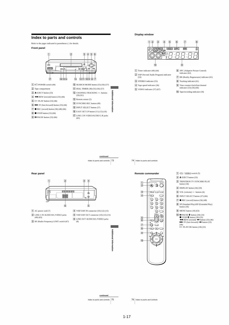
1-17
73Index to parts and controls
Ad
ditio
nal In
form
ation
Index to parts and controlsRefer to the pages indicated in parentheses ( ) for details.
Front panel
A ?/1 POWER switch (44)
B Tape compartment
C Z EJECT button (33)
Dm REW (rewind) button (33) (46)
EH PLAY button (33) (46)
FM FF (fast-forward) button (33) (46)
G z REC (record) button (36) (48) (66)
H x STOP button (33) (66)
I X PAUSE button (33) (66)
J SEARCH MODE button (55) (56) (57)
K DIAL TIMER (38) (55) (56) (57)
L CHANNEL/TRACKING +/– buttons (36) (61)
M Remote sensor (5)
N SYNCHRO REC button (49)
O INPUT SELECT button (37)
P EASY SET UP button (11) (13) (16)
Q LINE-2 IN VIDEO/AUDIO L/R jacks (65)
continued
74 Index to parts and controls
Display window
A Timer indicator (40) (44)
B SAP (Second Audio Program) indicator (53)
C STEREO indicator (53)
D Tape speed indicator (36)
E VIDEO indicator (37) (67)
F APC (Adaptive Picture Control) indicator (62)
G RR (Reality Regenerator) indicator (61)
H Tracking indicator (61)
I Time counter/clock/line/channel indicator (33) (36) (66)
J Tape/recording indicator (36)
STEREOSAP LPSP
EP
RRVIDEO APC
75Index to parts and controls
Ad
ditio
nal In
form
ation
Rear panel
A AC power cord (7)
B LINE-1 IN AUDIO R/L/VIDEO jacks (49) (65)
C RF (Radio Frequency) UNIT switch (67)
D VHF/UHF IN connector (10) (12) (15)
E VHF/UHF OUT connector (10) (12) (15)
F LINE OUT AUDIO R/L/VIDEO jacks (8)
continued
76 Index to parts and controls
Remote commander A •TV / VIDEO switch (5)
B Z EJECT button (33)
C TRINITRON TV SYNCHRO PLAY button (34)
D DISPLAY button (36) (59)
E VOL (volume) +/– buttons (6)
F INPUT SELECT button (37) (66)
G z REC (record) button (36) (48)
H SP (Standard Play)/EP (Extended Play) button (36)
I MENU button (18) (63)
J X PAUSE/M button (18) (33)x STOP/m button (18) (33)m REW (rewind)/ < button (33) (46)M FF (fast-forward)/ , button (33) (46)H PLAY/OK button (18) (33)
1 2 3
4 5 6
7 8 9
0
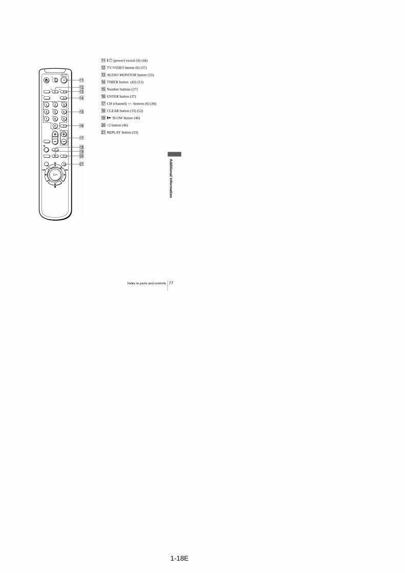
77Index to parts and controls
Ad
ditio
nal In
form
ation
K ?/1 (power) switch (6) (44)
L TV/VIDEO button (6) (37)
M AUDIO MONITOR button (53)
N TIMER button (43) (51)
O Number buttons (37)
P ENTER button (37)
Q CH (channel) +/– buttons (6) (36)
R CLEAR button (33) (52)
Sy SLOW button (46)
T ×2 button (46)
U REPLAY button (33)
1 2 3
4 5 6
7 8 9
0
1-18E

2-1
SLV-LX80S
SECTION 2DISASSEMBLY
NOTE: Follow the disassembly procedure in the numerical order given.
2-1. CASE, FRONT PANEL BLOCK ASSEMBLY
8 Two screws (B2.6 × 8)
5 Two screws (B2.6 × 8)
1 Five screws (B2.6 × 8)
2 DM-98 board
4 DI-81 board
7 FJ-28 board
6 Earth Plate
6 Flat Cable FDI-002
3 Flat Cable FDM-010
9 Flat Cable FDI-002
1 Two tapping screws
3 Upper case
2 Two tapping screws
6 Flat Cable FDM-010
7 Flat Cable FDI-002
5 Flat Cable FDI-002
8 Front panel (Engaged by the six hooks)
Hooks
Hooks
Hooks
Hooks
2-2. DM-98 BOARD, DI-81 BOARD, FJ-28 BOARD

2-2
2 MA-397 board with mechanism deck
1 Six screws (Sumitite (B3) +BV)
Hooks
Hooks
2 Rear panel (Engaged by the seven hooks)
1 POWER code stopper
Hooks
2-4. MA-397 BOARD
2-3. REAR PANEL
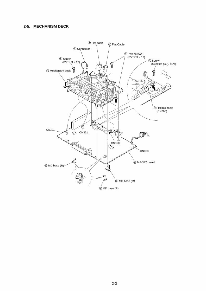
2-3
qa MA-397 board
7 MD base (M)
8 MD base (R)
0 MD base (R)
6 Two screws (BVTP 3 × 12)
9 Screw (BVTP 3 × 12) 2 Screw
(Sumitite (B3), +BV)
qs Mechanism deck
1 Flexible cable (CN260)
CN101CN351
5 Connector
3 Flat Cable4 Flat cable
CN350
CN600
2-5. MECHANISM DECK

2-4
2-6. INTERNAL VIEWS
— Top View —
— Bottom View —
M901Drum AssemblyDZH-0B7A-R 1-772-366-11
ACE head block assemblyA-6759-620-A
Pinch press block assemblyA-6759-863-B
Reel (T) table3-977-508-01FL complete assembly
A-6775-359-CReel (S) table3-977-507-01
FE head1-500-144-11
M902DC motor (capstan)1-698-971-11
Rubber belt3-977-510-01
M903Cam motor assemblyX-3947-577-1
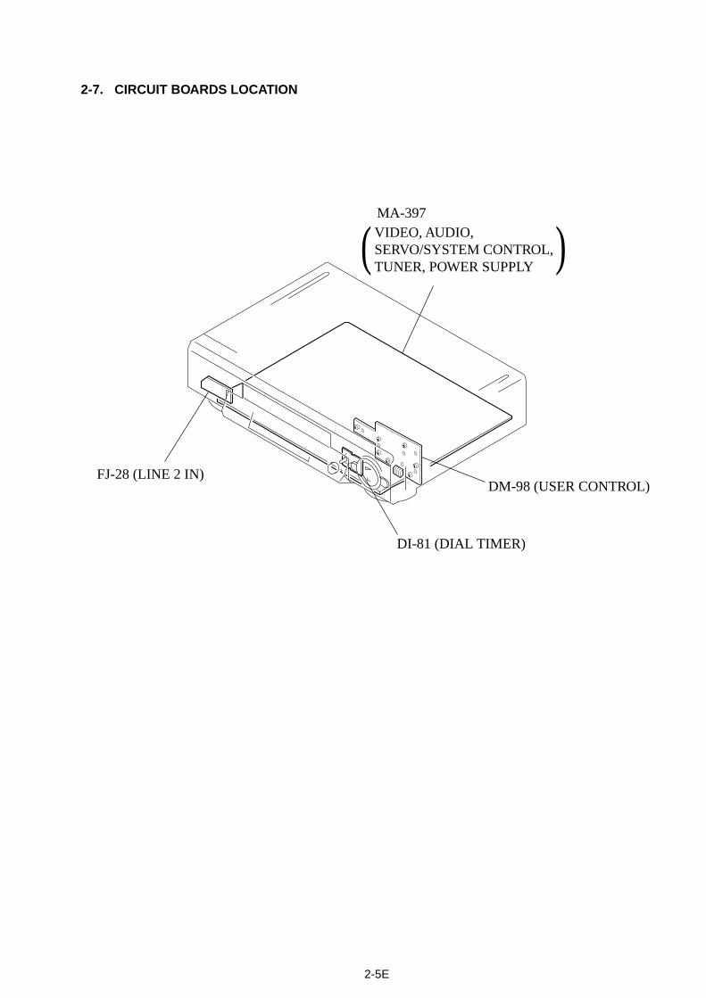
2-7. CIRCUIT BOARDS LOCATION
VIDEO, AUDIO,SERVO/SYSTEM CONTROL,TUNER, POWER SUPPLY
FJ-28 (LINE 2 IN)
DI-81 (DIAL TIMER)
DM-98 (USER CONTROL)
MA-397
( )
2-5E

SLV-LX80S
3-1 3-2
SECTION 3BLOCK DIAGRAMS
3-1. OVERALL BLOCK DIAGRAM

SLV-LX80S
3-2. VIDEO BLOCK DIAGRAM
3-3 3-4
IC201 wk REC/PB
H 4.2Vp-p
IC201 ej REC
1.0Vp-pH
IC260 5 REC/PB
3.5Vp-pH
IC260 7 PB
0.6Vp-pVIC201 1 PB
0.6Vp-pV
IC260 qj REC
3.8Vp-p0.1µsec/div1V/div
IC260 0 REC
380mVp-pH
IC260 9 REC
170mVp-p0.1µsec/div50mV/div
IC201 2 REC
380mVp-pH
IC201 ok
1.6Vp-p30Hz
RF SW PREC/PB
0.1µsec/div0.1V/div
IC201 7 REC
360mVp-p
IC201 wl REC
2.1Vp-pH
IC201 wl PB
2.3Vp-pH
IC201 wd PB
0.5Vp-pH
H
IC160 th
2.0Vp-p
C VIDEO INREC/PB
IC160 t; OSC V IN REC
2.2Vp-pH
IC160 t; OSC V IN PB
2.3Vp-pH
H
IC160 ts OSD V OUT PB
2.3Vp-pH
IC160 ts
2.2Vp-p
OSD V OUT REC
IC201 yj REC/PB
R 460mVp-p3.579545MHz
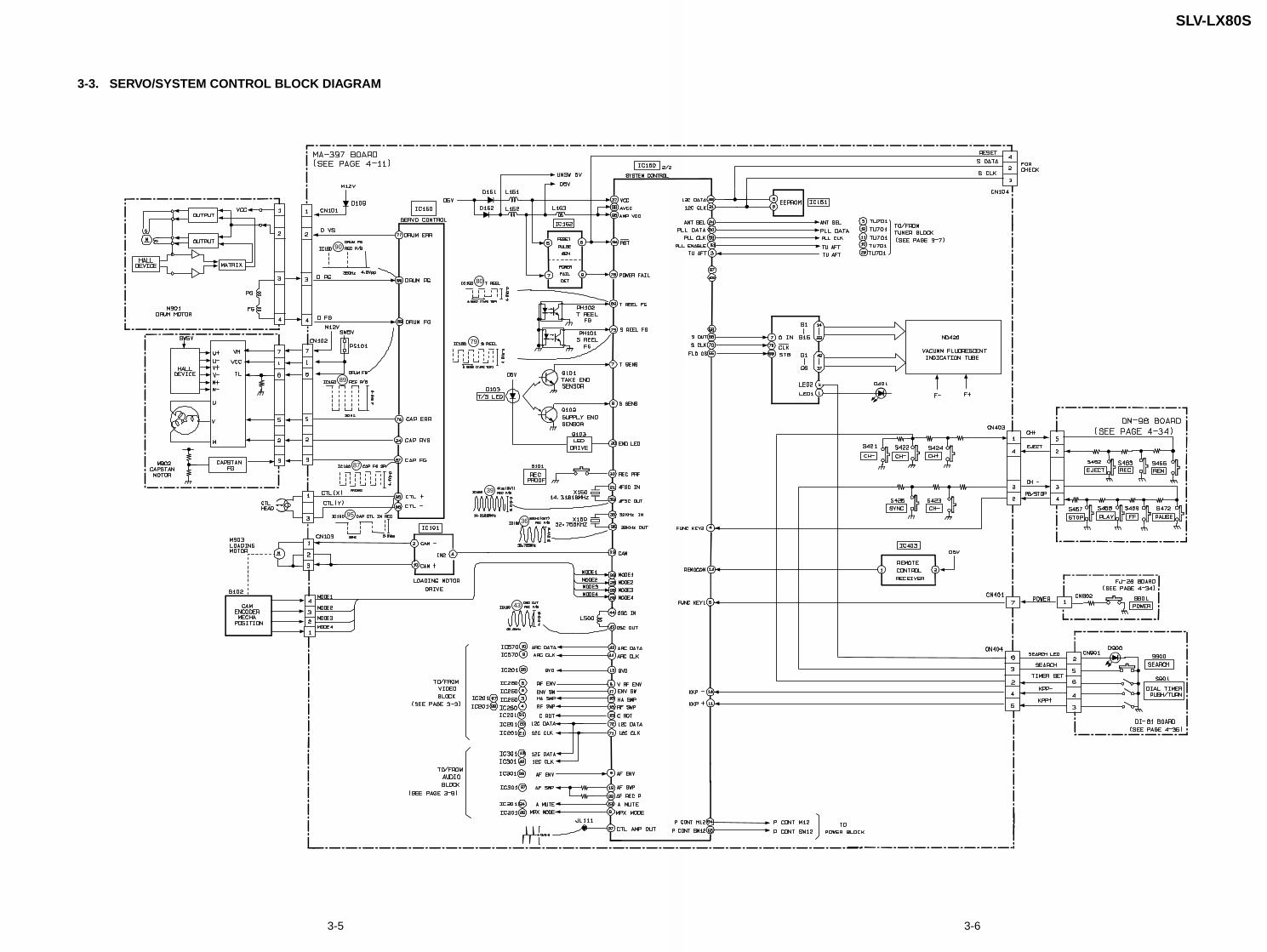
SLV-LX80S
3-3. SERVO/SYSTEM CONTROL BLOCK DIAGRAM
90
89
87
95
79
80
39
36
43
3-5 3-6

SLV-LX80S
3-4. TUNER BLOCK DIAGRAM
3-7 3-8
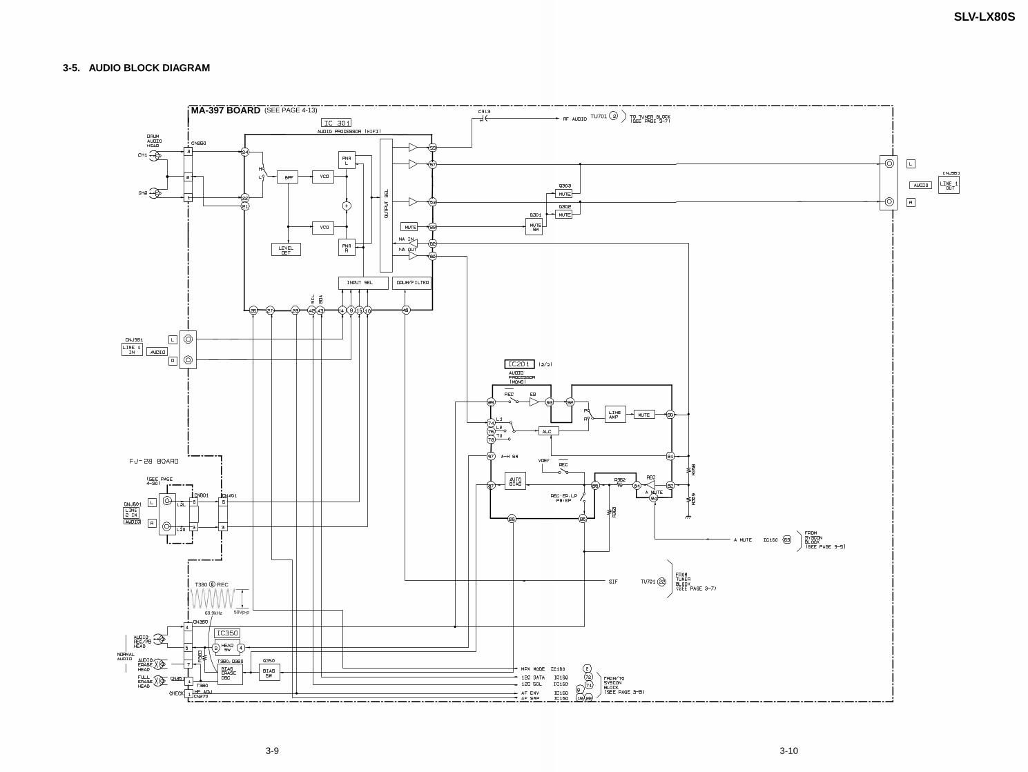
SLV-LX80S
3-5. AUDIO BLOCK DIAGRAM
MA-397 BOARD (SEE PAGE 4-13)
T380 6 REC
50Vp-p69.9kHz
TU701
3-9 3-10
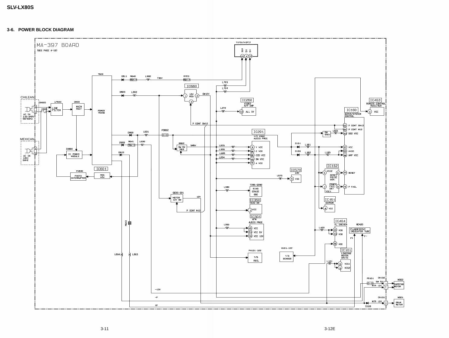
SLV-LX80S
3-6. POWER BLOCK DIAGRAM
CHILEAN
MEXICAN
3-11 3-12E
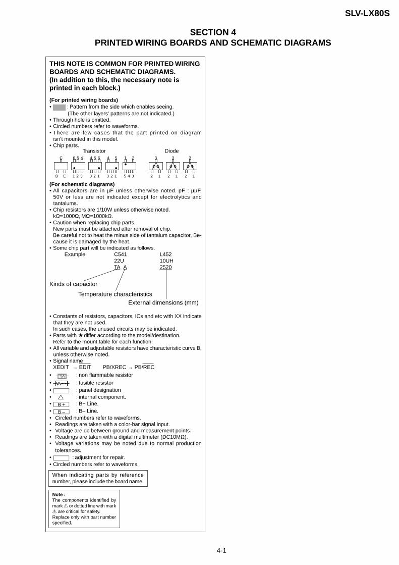
4-1
SLV-LX80S
(For printed wiring boards)• : Pattern from the side which enables seeing.
(The other layers' patterns are not indicated.)• Through hole is omitted.• Circled numbers refer to waveforms.• There are few cases that the part printed on diagram
isn’t mounted in this model.• Chip parts.
(For schematic diagrams)• All capacitors are in µF unless otherwise noted. pF : µµF.
50V or less are not indicated except for electrolytics andtantalums.
• Chip resistors are 1/10W unless otherwise noted.kΩ=1000Ω, MΩ=1000kΩ.
• Caution when replacing chip parts.New parts must be attached after removal of chip.Be careful not to heat the minus side of tantalum capacitor, Be-cause it is damaged by the heat.
• Some chip part will be indicated as follows.Example C541 L452
22U 10UHTA A 2520
• Constants of resistors, capacitors, ICs and etc with XX indicatethat they are not used.In such cases, the unused circuits may be indicated.
• Parts with differ according to the model/destination.Refer to the mount table for each function.
• All variable and adjustable resistors have characteristic curve B,unless otherwise noted.
• Signal nameXEDIT → EDIT PB/XREC → PB/REC
• : non flammable resistor
• : fusible resistor• : panel designation• : internal component.• B + : B+ Line.• B – : B– Line.• Circled numbers refer to waveforms.• Readings are taken with a color-bar signal input.• Voltage are dc between ground and measurement points.• Readings are taken with a digital multimeter (DC10MΩ).• Voltage variations may be noted due to normal production
tolerances.• : adjustment for repair.• Circled numbers refer to waveforms.
THIS NOTE IS COMMON FOR PRINTED WIRINGBOARDS AND SCHEMATIC DIAGRAMS.(In addition to this, the necessary note isprinted in each block.)
Transistor Diode
Kinds of capacitor
Temperature characteristicsExternal dimensions (mm)
When indicating parts by referencenumber, please include the board name.
C
B E
56 4
21 3
54 6
23 1
4 5
23 1
1 2
45 3
3
2 1
3
2 1
3
2 1
Note :The components identified bymark ! or dotted line with mark! are critical for safety.Replace only with part numberspecified.
SECTION 4PRINTED WIRING BOARDS AND SCHEMATIC DIAGRAMS

SLV-LX80S
A
1 2 3 4 5 6 7 8 9 10 11 12 13 14
B
C
D
E
F
G
H
I
J
4-3 4-4
4-1. FRAME SCHEMATIC DIAGRAM
FRAME SCHEMATIC DIAGRAM

SLV-LX80S
A
1 2 3 4 5 6 7 8 9 10 11 12 13 14
B
C
D
E
F
G
H
I
J
A
1 2 3 4 5 6 7 8 9 10 11 12 13
B
C
D
E
F
G
H
I
J
4-6
MA-397 (VIDEO, AUDIO, SERVO/SYSTEM CONTROL, TUNER, POWER) PRINTED WIRING BOARD— Ref. No. MA-397 Board:1,000 Series —
There are few cases that the part printed on this diagram isn’t mounted in this model.
VIDEO, AUDIO, SERVO/SYSTEM CONTROL, TUNER, POWERMA-397
MA-397 BOARD
CN101 G13CN404 I1CN600 A1
D102 H9D103 F7D109 F13D161 G8D162 G8D163 F13D302 A7D401 J10D420 I5D561 B4D562 B5D563 B4D600 B2D601 E2D604 E2D605 C2D607 D3D608 F2D609 F2D611 F2D612 F1D613 F1D614 H1D623 C1D624 C2D625 D1D660 I3D661 H3D666 H3D702 B12D980 A4D982 C3D983 A4
IC101 I4IC151 H12IC160 H10
IC162 H13IC201 D6IC260 B10IC301 A9IC350 B6IC403 J5IC404 I7IC570 F9IC600 D1IC601 G1IC660 H1IC870 G5IC871 H6IC980 C4
Q101 F3Q102 F11Q103 F7Q201 C6Q202 C5Q203 E6Q301 A7Q302 A7Q303 A7Q350 C8Q380 C7Q500 H8Q502 H9Q561 B5Q600 I1Q601 I2Q662 I2Q673 I3Q674 J2Q870 G5Q871 H7Q872 G7Q873 H5Q874 G5Q876 H7
4-2. PRINTED WIRING BOARDS AND SCHEMATIC DIAGRAMS
MA-397 Board (Side B)

SLV-LX80S
A
1 2 3 4 5 6 7 8 9 10 11 12 13 14
B
C
D
E
F
G
H
I
J
4-7 4-8REC/PB HEAD AMP
MA-397 (1/7)
MA-397 (REC/PB HEAD AMP) SCHEMATIC DIAGRAM– Ref. No: MA-397 Board; 1000 series –• See page 4-21 for waveforms
MA-397 BOARD(1/7)REC/PB HEAD AMP(RP BLOCK)•REF.NO.:1000 SERIES-XX MARK:NO MOUNT
NO MARK:REC/PB MODER :REC MODEP :PB MODE
VIDEO, AUDIO,SERVO/SYSTEM CONTROL,TUNER, POWER SUPPLY
FJ-28 (LINE 2 IN)
DI-81 (DIAL TIMER)
DM-98 (USER CONTROL)
MA-397
( )
JL263
0.1uB
C272
JL279
AN_GND
JL284
JL277
XXC268
JL287
0.01uBC271
IC260 LA70011
12
34
56
78
910
111213
1415
1617
1819
2021
2223
24
10V100uC280
0R267
22kR279
RS2
0.022uC278
B
JL273
VS3
22kR277
AU2
AU3
JL260
100uHL270
JL269
JL271
470R271
JL270
JL286VS7
0.01uB
C282
VA4
0.1uB
C276
0.1u BC279
AU_PB_RF
VS6
AU1
0.60mmR273
JL267
0.1uB
C267
JL262
VA5
SW_5V
JL282
470R270
JL261
0.22u BC284
JL266
JL278
6800R276
22kR278
3900R274
JL265
JL281
4PCN270
HF ADJ1
PB RF2
RF SWP3
AN_GND4
0.01uB
C281
JL280
JL272
0.5%
1800R272
AN_GND
JL268
VA7
VA1
VA2
RS1
JL264
0.01uC285
VA3
0.01u BC275
100pCH
C286
JL274
0.01uB
C283
11PCN260
1AUDIO CH2 L
2AUDIO REC
3AUDIO CH1 H
4FE
5AN_GND
6SP CH1 F
7SP CH2 S
8SP CH2 F
9EP CH1 F
10EP CH2 S
11EP CH2 F
AN
_GN
D
1
3
4
2
EP CH2
AUDIO CH1
7
SP CH1
AUDIO CH2
9
10
EP CH1
5
11
SP CH2
6
8
REC CURR ADJ
REC H
REC C
REC Y RF
PB RF
COMP SYNC
TRICK H
RF ENV
RF SWP
HA SWP
ENV SW
AUDIO CH2
AUDIO REC
AUDIO CH1
AM
P
H.S
YN
C
AM
P
DET
H
ATT
VC
C
SW
30
AM
P
PB
OFF
BIA
S
SP
ALL 5V
CO
NT
SP
OFF
10k
PB
ON
CO
MP
AM
PREC
AG
C
EP O
FFC
UR
REN
T
AG
C
VC
C
CU
RR
ENT 1k
ENV
ELO
PE
VCC L
HA
TO H
A
REC
OFF
SW30
H.S
YN
C
AM
P
AM
P
EPH
A
VC
C
EP O
FF
PB
OFF
DET
SP
OFF
REC
10k
BIA
S
IC260 VIDEOREC/PB AMP
4.9
R4.2/P4.9
R1.4/P0
R3.9/P2.0
R3.8/P2.0
R2.5/P0
R3.9/P2.0
R1.6/P2.0
R1.6/P2.0
R2.5/P0
R1.6/P2.0 R2.0/P4.2
R0.2/P0.5
0
1.8
0.3
R0/P2.6
R0/P1.6
R3.4/P0
R3.4/P0.4
R4.1/P0
R3.2/P2.5
MA-397(2/7)(SEE PAGE 4-10)
MA-397(3/7)(SEE PAGE 4-11)
MA-397(7/7)(SEE PAGE 4-19)
MA-397(4/7)(SEE PAGE 4-13)
1
2
3
4
2
1
5
3
4
6
REC
PB
VIDEO SIGNAL
CHROMA Y/CHROMAY
AUDIOSIGNAL
SIGNAL PATH
CHECK
B+ B+
B+
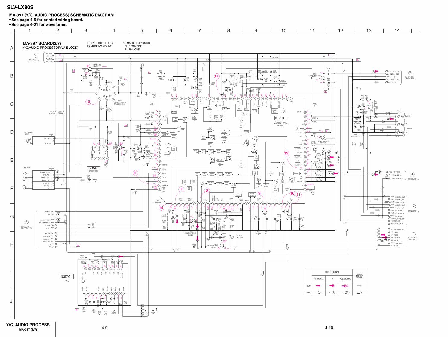
SLV-LX80S
A
1 2 3 4 5 6 7 8 9 10 11 12 13 14
B
C
D
E
F
G
H
I
J
JL21
1
18kR371
18kR363
JL368
JL307
47R380
2SA1162Y-TE85LQ203
VA5
0.1uB
C251
180pC214
0.60mmJS572
50V1u
C216
SW_12V
7PCN350
1CTL (X)
2CTL (Y)
3GND (AU)
4A HEAD PB
5A HEAD REC
6GND (AU)
7AERASE HEAD
100R219
1uC221
B
0.047uB
C250
JL207
1/10W
68kR350
XXC361
VA2
C5700.01u
B
±0.
5%10
0kR
205
XXD563
25V47uC351
L350XX
XXR206
0.01uC382
L206100uH
0.60mmJS303
JL20
8
C5770.01u
B
16V10u
C354
XXC579
330kR365
1uC245
B
VS2
16V22uC223
C571
10V1u
JL57
1
C576
10V100u
330R203
HM4220uHL207
5600R209
JL213
JL30
1 0.04
7uB
C24
8
8200R366
0.1u BC235
1800R216
0.1u BC224
1kR213
R57010k
0R208
0.1uB
C255
JL220
JL323
C574
16V10u
HV3
L2_V
FSC_FOR_ADJ
HT3
VS8
16V47u
C362
VS11
1uC244
B
0.01u BC236
2SD601A-QRS-TXQ204
JL320
0.1uB
C206
100k
R57
7
R571470
VA7
2SC2712Y-TE85LQ201
C5780.01u
B
10pC215
1kR574
JL322
0.01uC381
820R369
0.60mmJS302
C203XX
XXD562
560pC371
560R212
0.01uB
C237
JL20
2
1801/4W
R563
50V1uC350
16V10uC233
100u
HL2
02HV6
8200R215
3900R381
LA72
77M
-TLM
IC57
0
1
C O
UT
2 3 4
Y O
UT
5
VC
C
6
FIL
AD
J
7
MO
NI
1
8
MO
NI
2
9
CLK
10
DAT
A
11
MA
IN O
FF
12
SU
B
13
SU
B
14
SU
B
15
SU
B
16
GN
D
17
REG
18
Y I
N
1920
C I
N
0.001uC359
XXC384
50V
1uC366
BA
7755
AF-
E2IC
350 1 2 3 4
5678
0.1u FC230
0.60mmJS301
XXC219
C5750.01u
B
0.1uB
C227
C572
50V4.7u
IC201LA71053M-MPB
1 2 3 4 5 6 7 8 9 10 11 12 13 14 15 16 17 18 19 20 21 22 23 24 25 26 27 28 29 30
3132
3334
3536
3738
3940
4142
4344
4546
4748
4950
515253545556575859606162636465666768697071727374757677787980
8182
8384
8586
8788
8990
9192
9394
9596
9798
9910
0
5600R351
2SB7
09A-
QR
S-TX
Q56
1
0.1u BC229
8200R357
VS6
RD8.2ES-T1BD561
16V
47uC209
1501/4W
R562
C573
16V0.33u
JL30
6
16V47uC238
0.01uB
C202
CNJ561
39pC207
JL219
0.022uB
C247
SW_5V
2SD1620-TDQ380
AN_GND
HT3
VS12
VS1
VS1
1800R358
16V47u
C383
0.01u BC239
PET0.047uC380
AN_GND
1uC204
B
1uC249
B
JL222
47u25V
C562
0.01uB
C368
0.01uB
C242
HM5
VS15
HV1
L201
39uH
XXR222
JL215
2SC2712Y-TE85LQ202
0R221
50V1uC225
HS3
HM5
T3801 2 3
456
7 8
0R220
680R225
0.01
uB
C20
5
100uHL561
12kR370
330R561
JL218
L204100uH
0.022uB
C217
5600R367
180R383
JL20
5
L205100uH
680R223
XXC370
0.01uB
C561
VA4
HM4
3PCN351
1
2
3
0.01
uBC20
8
16V10uC364
4700R359
1uB
C254
8200R204
JL561
100k
R57
6
50V4.7uC363
50V
1uC358
16V47u
C240AU_GND
L570100uH
JL570
HS4
560R372
330R201
CTL_X
2.2MR354
XXC212
1500R214
HV2
820
R20
2
47kR224
0.1u BC210
470u10V
C563
JL20
6
0.1u BC226
VA3
2700pC360
0.01uC252
0.01uB
C220
AU_GND
JL21
0
16V10u
C222
X20
13.
5795
45M
Hz
0.01
uC
243
270R364
2SC
1815
GR
-TP
E2Q
350
0.01uB
C241
47kR231
CTL_Y
XXR207
VS3
JL57
2
JS570
0.01uC246
1uC232
B
JL20
9
100uHL380
C213390p
0.047uB
C201
VS13
VT2
JL214
HV5
JL203
JL217
68R564
HV4
JL20
1
8200R573
1200R362
JL30
4
JL20
4
4700R211
JL321
0.01uB
C365
16V47uC231
JL30
8
C3520.1u
JS571XX
R572470
25V33u
C356
50V4.7u
C357
JL560
XXC564
L20310uH
39pC253
4700R575
VS15
1uC234
B
16V47uC228
75R565
VA1
XXC218
33pC211
1R382
JL305
1500R210
C1
C3
C2
C6C
3
C4
C4
D2
D2
E5
C5
C1
E1
D7
D8
SW_12V
E7
E5
D4
D5
C2
D4
D5
C6
D7
D8
C5
CTL_Y
CTL_X
E8
E1
E7E8
AU_GND
AN_GND
RF VIDEO
L1_AUDIO_R
L1_AUDIO_L
AUDIO_R_OUT
AUDIO_L_OUT
A MUTE
GND (AU)
FE HEAD
TRICK-H
REC H
REC CURR ADJ
REC Y RF
REC C
PB RF
Q VD
I2C CLK(VIDEO)
I2C DATA(VIDEO)
RF SW P
C ROT
ACC
Chara
R
INS.
P
6dB
P
AMP
SYNCSEP
VIDEOAGC
CLAMP
CLAMP
FBC
CLAMP
CLAMP
TC2AGC
SW-Vcc
REG
CLAMP
P
ACC
R
DET
YNR
FILT
R
REC-EP.LP
LPF
PB-EP
1/2
REC
FBC
PB-LP.SP
R
Y-Vcc
P
RF SWP
P
C.ROT
R
HASW
P
REC-H
R
TRICK-H
1
CC
D V
CC
2 3
1HD.L
R
N.C
KIL
60/50
R
VCA
C-LPF
SW GND
P
A-Vcc
B.D.
ALC
KIL
DET
ENH
A-GND
DETAIL
C-G
ND
EMPH
N.C
N.L
N.C
AGC
N.C
EMPH
D.L
TC1
1H/2H
PB
4Fsc
Main
LA71053
EQ
FM
CC
D G
ND
EQ
NTS
C:H
MOD
C-V
cc
BAL
CLK IN
FM
AFC
REC
FILT
EQ
N.C
SQPB
P
DOUBLE
P
LIM
P
DEMOD
R
LPF
P
SUBS
N P R
SERIALDECODER
DETSYNC
DETFMAGC
CLAMP
VID
EO
FILTM-Em
CTLEQ
FILPEA
KIN
G
N.LY GND
R
BPF2
BGA
PB
PBBGA-A
REC
BGA-B
BRA
RAMP
A MUTE
ACC P
APCREC REC
AMP
REC
EQ
APC
AUTO
APC
BIAS
VXO1
P
KIL
R
DET
REC
AMP
AMP
VCO
MUTESLD
AMP
INV
LINE
EQ
Vref
D.L
ALC
BPF1Vref
TH
REC
LPF
P
Sub
R
COVN
MIX
Sub
CONT
BPF
De-EM
Main
NC
CONV
DHP
B-UP
PIC
AMP
N.L
AMP
Y/C
ARC CLK
ARC DATA
VIDEO OUT
OSD V OUT
PB-H
VXO2
TU VIDEO IN
RF AUDIO
NORMAL_OUT
NORMAL_IN
L2_AUDIO_L
RF_AUDIO_OUT
L1L2TU
COMP SYNC
AN_GND
L2(L)
AU_GND
VIDEO
L
R
INOUT
L2_AUDIO_R
L2(R)
L2_VIDEO
AUDIO_MUTE
B+
B+
B+
IC201 Y/C PROCESSORAUDIO PROCESSOR
0
2.3
2.4
2.4
R0.6/P5
R1.6/P5
R0.8/P0
2.4
2.4
2.3
R3.1P2.3
2.3
0
R4.1/P0
0.8
R3.3/P0.2
0.8
4.2
R1.6P2.0
R0/
P2.
5
R2.
4/P
0.3
2.3
2.6
2.0
2.0
3.1 0
R2.
4/P
2.0
R0.
2/P
1.8
1.1
R1.
5P
1.7
2.2
R2.
4/P
1.6
R2.
4/P
1.5
R3.
1/P
2.5
3.1
3-3.
7 4.6
4.8
2.3
R0.
1/P
1.5 0
1.8
0.3 1.8
3.4
3.0
R2.2/P0.3
1.5
R1.7/P0
2.0
R2.1/P0
4.1
R3.2/P1.3
3.0
3.0
3.1
1.9
4.9
2.2
1.4
9.0
2.0
0.8
1.8
2.5
4.9
2.5
4.9
4.9
3.4
3.3
3.3
3.4
3.32.1
2.5
1.9
2.3
5.0
2.3
2.2
2.3
1.6
5.0
1.4
2.1
B+
5.0
R2.4/P2.1
R1.8/P1.4
2.0
1.3
3.7
2.6
2.8
1.8 4.1
1.9
1.8
2.6
2.4
2.1
2.9
2.3
1.8
4.9
1.1
5.0
5.0
5.0
0
R3.
3P
0.2
2.4
B+
B+
B+
B+
B+
B+
B+
3.3
2.6
B+
16
14
13
1110987
15
12
R1.7/P5 R4.7/P5
R1.8 P5
MA-397(6/7)(SEE PAGE 4-17)
7
MA-397(5/7)(SEE PAGE 4-15)
8
MA-397(4/7)(SEE PAGE 4-13)
9
1 MA-397(1/7)(SEE PAGE 4-7)
AUDIO
MA-397(3/7)(SEE PAGE 4-11)
6
5
MA-397(7/7)(SEE PAGE 4-19)
R1.6/P5
R0.
8/P
0
REC
PB
CHROMA Y Y/CHROMA
VIDEO SIGNAL
AUDIOSIGNALIC570
ARC
BUFFER
BUFFER
HEAD SWITCH
IC350
BIA
S S
WIT
CH
BIAS OSCILLATOR TRANSFORMER
BIAS OSC
BUFFER
BUFFER
FULL ERASE HEAD
ACE HEAD
4-9 4-10
MA-397 (Y/C, AUDIO PROCESS) SCHEMATIC DIAGRAM• See page 4-5 for printed wiring board.• See page 4-21 for waveforms.
MA-397 BOARD(2/7)Y/C,AUDIO PROCESSOR(VA BLOCK)
•REF.NO.:1000 SERIES-XX MARK:NO MOUNT
NO MARK:REC/PB MODER :REC MODEP :PB MODE
Y/C, AUDIO PROCESSMA-397 (2/7)

SLV-LX80S
A
1 2 3 4 5 6 7 8 9 10 11 12 13 14
B
C
D
E
F
G
H
I
J
JL112
JL114
JL162
IC162MM1256XF-BE
12
34 5
67
8
JL111
JL110
JS1010.60mm
2200pB
C146
Q10
32S
C18
15G
R-T
PE2
PH102GP3S120S
R101470
1/4W
Q10
1P
T380
F3
C1040.001u
B
C105330u6.3V
R112 4700
XXC114
PS101
F
C1071u
JL106
C1010.001u
B
JL102
R10522k
1/4W
10kR114
D102XX
16V47u
C106
JL108
C1020.001u
B
S101
R10422k
10kR113
D101XX
R10315k
CN1033P
1
2
3
JL107
JL101
R10639
1/4W
S102
R10215k
D103GL528V1
JL104
C1030.001u
B
R107391/4W
PH101GP3S120S
Q10
2P
T380
F3
JL109
C110XX
47kR109
0.01uB
C1120.01uB
C111
0.01uB
C1150.01uB
C116
47kR11547k
R116
2.2uHL101
470R117
0.1uB
C108
0.1uB
C109
IC101 LB1943N
1 2 3 4 5 6 7 8 9 10
47kR110
47kR118
15kR119
MPG06D-6052PKG3D109
2200R111 1k
1/4W
R120
4700R143
JL166
JL161
JL169
JL185
XXC186
1uF
C187
XXC188
XXC189
16V47u
C190
XXC191
XXC192
CN1029P
1
2
3
4
5
6
7
8
9
XXJS103
JL103
JL105
JL115
JL116
JL117
JL118
JL119
JL120
JL121
JL122
JL123
JL124
JL125
XXR123
TS5
TS4
TS3
TS2
TS1
VS15
VS13
RS2
VS7
VS6
RS1
VS8
VS6
HS4
HS3
VS2
VS1
HS5
HS4
HS3
HS2
HS1
MS12
MS11
MS10
MS7
MS6
MS4
MS3
MS2
MS1
PS2
PS1
MTR_12V
D_6V
SW_5V
AN_GND
MTR_GND
D_GND
SW_12V
10k
R16
9
10k
R16
8
0.047uB
C160
0.047uB
C161
47kR164
47kR165
3300R162
1/4W
C1620.1u
F
C1720.01u
B
C1730.01u
B
220kR178
470kR179
18p
CH
C16
7
C16
6
27pCH
C16424pCH
C165
0.04
7uB
C16
3
14.3
1818
MH
zX
160
32.7
68kH
zX
161 39
0R
174
10k
R17
2
4PCN104
1D_GND
2S-DATA
3S-CLK
4RESET
680p CHC507
470R507
0.1uB
C510
1uB
C508
3900pB
C509
1500R508
1MR509
470
R17
7
1/4W 47
0
R17
6
1/4W
470
R17
5
680pCH
C170
0R187
0R185
0R183
3300R170
3300R1896800R188
10kR166
1/4W15k
R167
10V470uC145
50V
22u
C14
4
50V22u
C143
10V100uC140
C1420.022u
B
0.1uF
C141
XXR173
47kR171 12
00R
142
22uHL163
2.2u
HL5
00
15pCH
C50015pCH
C501
0.01uB
C502
4700
pB
C50
3
1kR
500
10V100uC168
0.1u F
C16
9 C171
5.5V0.33
22uHL162
22uHL161
MPG06D-6052PKG3D162
MPG06D-6052PKG3D161
XXC174
680R505
1kR504
1kR503
CH
C50510p
2SB709A-QRS-TXQ500
0.001uCH
C504
0R502
VS11
VS12
470R121
JL16
3
JL16
4
JL500
JL50
1
0.60mmJS161
JL16
0
0.60mmR190
1kR19
1
1kR
192
100uHL501
FC
511
0.1u
10V
100u
C51
2
XXC175
JL186
0.60
mm
R51
0
0.60
mm
R51
1
0R193
0.60mmR195
10kR194
0.001uB
C513
JL170
2SA1162Y-TE85LQ502
0R512 1/4W
470R513
JL127
JL126
JL130
JL129
JL128
JL13
2
JL13
1
1kR160100kR159
0.1uB
C113
3300
R18
0
0.60
mm
JS16
3
0.1uB
C176
XXC185
JL13
3
B0.
001u
C51
4
XXC515
10kR161
IC160
M37760M8H115GP
12
34
56
78
910
1112
1314
1516
1718
1920
2122
2324
2526
2728
2930
31 32 33 34 35 36 37 38 39 40 41 42 43 44 45 46 47 48 49 5051
5253
5455
5657
5859
6061
6263
6465
6667
6869
7071
7273
7475
7677
7879
80
81828384858687888990919293949596979899100
XXJS520
JL134
JL13
5
JL13
6
JL13
7
JL13
8
HS7
OSD_VCC
CTL_X
CTL_Y
MTR_GND2
IC161M24C02-WMN6T(A)
XXD163
0.60mmJS521
5PCN101
1 MTR 12V
2 D VS
3 D PG
4 D FG
5 MTR GND
M
M
M
S5
S8
S9
S18 S16
S15
S11
S7
S6
S17
S1
S2
S4
S3
S14
S13
S10
M7
M6
M3
M2
M2
M1
M6
M7
S15
S16
S13
S8
S1
S2
S3
S4
S14
S10
S5
S17
S18
V9
V4
V11
V1
V9
V4
V2
V1
M3
T5
T4
T3
T2
T1
T2
T3
T4
M1
S9
S6
S7
S11
T1
T5
V11
V6
V7
V7
V6
D5V
D_G
ND
AN_GND
MTR_GND
MTR_GND2
V2
DATA
CLKOUT 1
VCC 1
OUT 2
VCC 2
CTL
S REEL FG
CAM(+)
LIMITER
MTR GND
T/S.LED
S.SENS
CTL-REFCAP VS
AN GND
T REEL FG
T.SENS
CAP RVS
SW 5V
CAM(-)
CAM(+)
ICP-N5
MTR 12V
REC PRF.
CAP FG
CA
M(-
)
VC
L
VC
H
V R
EF
VC
C 1
VC
C 2
MTR
GN
D
IN 1
CA
M(+
)
IN 2
WP
DEST
MPX MODE
TU AFT
FUNC KEY2
FUNC KEY1
S SENS
T SENS
V RF ENV
AF ENV
CBC ON
KKP +
KKP -
QVD
REMOCON
C ROT
HA SWP
ENV SW
RF SWP
AF SWP
END LED
ANT SEL
AF REC P
N.C
CAP RVS
N.C
MODE4
MODE3
MODE2
MODE1
REC PRF
I2C
CLK
EEP
I2C
DAT
A E
EP
CA
M
RES
ET
32kH
z(in
)
32kH
z(ou
t)
Vcc
4fsc
(in)
4fsc
(out
)
Vss
AR
C C
LK
AR
C D
ATA
CLK
SEL
OS
C I
N
OS
C O
UT
NU
B
LPF
SP
OS
D G
ND
OS
D V
IN
WHITE LEVEL/ LECHA
OSD V OUT
OSD Vcc
HLF
VHOLD
C VIDEO IN
NUA
N.C
PLL CLK
PLL DATA
PLL ENABLE
NC
A MUTE
P CONT M12
P CONT SW12
FLD CS
V-SET CS
S OUT0
S IN0
S CLK0
I2C CLK
I2C DATA
CBC SIRCS OUT
CLKOUT
NICOLE
CAP ERR
DRUM ERR
P FAIL
S REEL
T REEL
DM
S +
DM
S -
MA
IN/S
AP
F M
ON
O
STE
REO
SA
P
CA
P F
G
AM
P V
ss
DR
UM
FG
DR
UM
PG
AM
P V
ref
OU
T
AM
P V
ref
IN
RC
CH
ECK
CTL
- I
N
CTL
+ I
N
AM
P C
CTL
AM
P O
UT
AM
P V
cc
AV
cc
V-S
ET R
ESET
TV/VTR
PLL CLOCK
PLL DATA
PLL ENABLE
TU AFT
VIDEO OUT
OSD V OUT
RF ENV
RF SWP
HA SWP
ENV SW
A MUTE
Q VD
I2C CLK
I2C DATA
RF SWP
C ROT
AF REC P
AF SWP
I2C DATA
I2C CLK
AF ENV
KKP -
KKP +
D5V
FLD CS
S OUT0
S CLK0
FUNC KEY2
FUNC KEY1
REMOCON
P CONT SW12
P CONT M12
ARC CLK
ARC DATA
MPX MODE
B+
B+
B+
B+
B+
B+
B+B+
B+
B+
B+B+
B+B+
B+
B+
B+
B+
B+
MA-397(7/7)(SEE PAGE 4-19)
MA-397(6/7)(SEE PAGE 4-17)
MA-397(4/7)(SEE PAGE 4-13)
MA-397(2/7)(SEE PAGE 4-9)
MA-397(1/7)(SEE PAGE 4-7)
MA-397(5/7)(SEE PAGE 4-15)
MA-397(2/7)(SEE PAGE 4-9)
MA-397(7/7)(SEE PAGE 4-19)
MA-397(2/7)(SEE PAGE 4-9)
OPEN
5
11
12
6
2
13
6
6
10
0
4.8
4.8
2.4
2.4
R2.
8/P
2.4
R2.
0/P
2.4
4.8
2.4
2.4
0.2
2.8
2.3
5.0
5.0
4.7
4.9
4.9
4.9
4.9
4.9
R0/P2.5
R0.1/P3.2
4.9
R0/P5.0
0
4.9
2.5
0
0.6
2.5
2.5
2.5
5.0
R0/P5.0
5.0
0
0
0
5.0
5.0
5.0
5.0
2.2
4.8
1.5
1.4
5.0
2.1
2.2
5.0
4.9
5.0
2.3
2.3 1.4
1.8
0
1.8
5.0
2.0
2.6
1.9
0
0
0
0
4.9
4.9
2.0-3.1
4.9
4.9
4.9
3.1-3.9
2.6
2.7
0.1-4.9
0.1-4.9
4.8
0.2 2.2
4.8
6.3
13.5 0.
2
13.5
4.9 4.9
1.6
0.4
1.5
2.5
4.8
4.8
4.9
5.0
5.0
5.0
5.0
1.82.5BUFFER
BUFFER
TAK
E EN
D
SEN
SO
R
SU
PP
LY E
ND
S
ENS
OR
LED
DR
IVER
LOADING MOTOR DRIVE
IC101
SERVO SYSTEM CONTROL
IC160
IC161 IC162EEPROM POWER FAIL DET
RESET PULSE GEN
REC REC/PB PB
DRUM SPEED SERVO
DRUM PHASE SERVO
DRUM SERVO(SPEED AND PHASE)
CAPSTAN SPEED SERVO
CAPSTAN SERVO(SPEED AND PHASE)
SERVO REFERENCE SIGNAL
2827
26 25 24
22
23
21
19
181729
M901DRUMMOTOR
M902CAPSTANMOTOR
M903CAMMOTOR
CAM ENCODER
4-11 4-12
MA-397 (SERVO/SYSTEM CONTROL) SCHEMATIC DIAGRAM• See page 4-5 for printed wiring board.• See page 4-22 for waveforms.
SERVO/SYSTEM CONTROLMA-397 (3/7)
Note :The components identified bymark ! or dotted line with mark! are critical for safety.Replace only with part numberspecified.
MA-397 BOARD(3/7)SERVO/SYSTEM CONTROL(SS BLOCK)
•REF.NO.:1000 SERIES-XX MARK:NO MOUNT
NO MARK:REC/PB MODER :REC MODEP :PB MODE

SLV-LX80S
A
1 2 3 4 5 6 7 8 9 10 11 12 13 14
B
C
D
E
F
G
H
I
J
4-13 4-14
MA-397 (AUDIO PROCESS) SCHEMATIC DIAGRAM• See page 4-5 for printed wiring board.
AUDIO PROCESSMA-397 (4/7)
MA-397 BOARD(4/7)AUDIO PRO0CESS(AU BLOCK)•REF.NO.:1000 SERIES-XX MARK:NO MOUNT
NO MARK:REC/PB MODER :REC MODEP :PB MODE
16V10u
C328
1SS
119-
25TD
D30
2
16V10u
C341
HS3
50V4.7uC323
47kR318
XXR317
JL319
JL312
JL328
AU3
50V4.7uC320
JL326
JL325
25V47u
C304
16V10u
C342
50V10u
C312220
R306
47kR319
AU2
HM5
HV3
50V10u
C310
0.1uC339
IC301AN3668FBP
1 2 3 4 5 6 7 8 9 10 11 12 13 14 15 16
1718
1920
2122
2324
2526
2728
2930
3132
33343536373839404142434445464748
4950
5152
5354
5556
5758
5960
6162
6364
XXL301
0.22uC334
50V2.2uC311
XXR307
Q3012SA1162Y-TE85L
HS2
JS31
1
16V10u
C322
JL311
2SC2712Y-TE85LQ303
0.1uC333±
5%33
kR31
6
0.1uC319
JL310
JL331
25V47u
C305
R3031k
0.22uC343
0.01uC302
JL330
HV1
50V10u
C313
47kR313
100uHL303
R3230
XXB
C335
JL313
50V10uC314
FSC_FOR_ADJ
0.015uC330
JL314
16V10u
C329
R30856k
AU_GND
50V1u
C3270.1u
B
C321
XXL302
HT3
AU1
JL317
16V10u
C324
16V47u
C332
25V33u
C326
AU_PB_RF
0.1uC303
0R310
50V4.7uC325
2SC2712Y-TE85LQ302
0.015uC340
0.1uC301
0.01uC338
0.1uC309
HS4
47kR314
SW_5V
1SS119-25TDD301
SIF
25V33u
C331
JL318
HV2
JS31
2
HM4
XXR315
XX
JS313
XXR312
HS5
1uC308
JS304
SW_12V
HV5
HS7
JL327
1kR301
HS1
0R311
XX
R334
HV6
JL329
50V3.3uC316
XXR322
JL315
0.1uC336
AN_GND
0.022uC337
JL316
0.1uC317
HV4
R3021k
0.022uC306
50V10u
C315
0.01uC345
XXR320
JL324
50V3.3uC318
R3213300
220R305
VS1
50V2.2uC307
AN_GND
SW_12V
SW_5V
AU_GND
L1R
L2R
L1L
L2L
VCC5V
OUT R
L+RREF
GND
MPXMODE
OUT L
VCC12V
RFC OUT
RFC AGC
NA OUT
NA IN
SIF
FSC
SD
A
SC
L
VC
C5V N
.C.
GN
D R
REC
AD
J
RPVCC5V
PB IN1
R/P GND
PB IN2
REC OUT
VR
EF
INR
EF R
L1 R
L2 R
GN
D L
INR
EF L
L1 L
L2 L
+
DEM/FILTER
SAP DEMOD
(L-R)/SAPSwitch
OUTSEL
dbxNR. IN SEL
PNR Lch
VCO R
VCO L
BPF
PNR Rch
FMLIMITER
DETNOISE
ENVDETHL
OFF
ON
EEmoniter
INSWMUTE
MUTEINSW
SWP
OFF
ON
ON
OFF
±10%
±10%
AUDIO_R_OUT
AUDIO_L_OUT
RF_AUDIO_OUT
NORMAL_OUT
NORMAL_IN
L1_AUDIO_R
L1-AUDIO_L
L2_AUDIO_R
L2_AUDIO_L
I2C_DATA
I2C_CLOCK
AF_REC
AF_ENV
AF_SWP
AUDIO_CH1
AUDIO_REC
AUDIO_CH2
MPX_MODE
AUDIO MUTE
B+
B+
B+
IC301AUDIO PROCESS
MA-397(5/7)(SEE PAGE 4-15)
MA-397(7/7)(SEE PAGE 4-19)
B+
5.0
6.0
2.2
6.0
12.0
6.0
2.5
2.2
2.5
0.3
2.5
2.2
0 0
2.2
2.50 0
2.2
0 2.2
0-5
0-5
5 1.7
2.5
0.4-
0.7
2.5
2.5
0
1.8
5.0
0-5
2.1
5.0
R2.1/P0.7
R2.1/P0
R2.1/P0.7
2.5
2.5
R2.1/P0
0.4-0.7
1.5
1.5
0.66
0.66
0.66
MUTE
MUTE
POWER MUTE
MA-397(2/7)(SEE PAGE 4-9)
MA-397(1/7)(SEE PAGE 4-7)
MA-397(3/7)(SEE PAGE 4-11)
AUDIOSIGNAL
REC
PB
12
4
9
15
14
SIGNAL PATH

SLV-LX80S
A
1 2 3 4 5 6 7 8 9 10 11 12 13 14
B
C
D
E
F
G
H
I
J
MA-397 (TUNER) SCHEMATIC DIAGRAM• See page 4-5 for printed wiring board.
4-15 4-16
MA-397 BOARD(5/7)TUNER(TU BLOCK)•REF.NO.:1000 SERIES-XX MARK:NO MOUNT
TUNERMA-397 (5/7)
Note :The components identified bymark ! or dotted line with mark! are critical for safety.Replace only with part numberspecified.
JL705
16V100uC709
TS4
1/4W560
R723
JL702
JL716
JL701
JL703
SW_5V
AN_GND
JL711
JL704
JL715
XXC705
16V100uC712
VS15
TU701
2 3 4 5 6 10 11 12 13 14 15 16 17 18 22 23 24
JL717
TS3
R7120
2200pB
C707
R702
33001/10W
HT3
RD
33ES
-T1B
3D
702
VT2
0.22uC794
B
TS1
TS5
560R704
JL713
TS2
+30V
JL718
1/4W390
R703
SIF
470kR724
1/10W
S701
0.01uB
C7020.01u
B
C710
0.01uB
C706
1kR701
1kR709
1kR710
1kR711
50V4.7uC704
25V47u
C701
2.2uHL703
2.2uHL704
470pC795
470pC796
470pC797
A5
A1
A4
A2
A3
A5
JS75
3
A1
AN
_GN
D
A2
A3
A4
RFCH
4CH
3CH
TV/VTR
PLL CLOCK
PLL DATA
PLL ENABLE
TU AFT
30V
5VDAT
A
5V CLO
CK
ENA
BLE
VID
EO I
N
CO
NT
CH
SW
IF O
UT
AU
DIO
IN
NC
IF I
N
SIF
OU
T
AFT
DET
OU
T
NC
TU VIDEO IN
RF V OUT
RF AUDIO OUT
B+B+
B+
B+
B+
B+
B+
MA-397(2/7)(SEE PAGE 4-10)
MA-397(7/7)(SEE PAGE 4-19)
MA-397(3/7)(SEE PAGE 4-11)
MA-397(2/7)(SEE PAGE 4-9)
MA-397(4/7)(SEE PAGE 4-13)
13
8
14
16
8
VIDEO SIGNAL
PB
Y/CHROMA
SIGNAL PATH
SIGNALAUDIO
REC

SLV-LX80S
A
1 2 3 4 5 6 7 8 9 10 11 12 13 14
B
C
D
E
F
G
H
I
J
4-17 4-18DISPLAY CONTROL
MA-397 (6/7)
MA-397 BOARD(6/7)DISPLAY CONTROL(FRONT BLOCK)•REF.NO.:1000 SERIES-XX MARK:NO MOUNTNO MARK:REC/PB MODE
MA-397 (DISPLAY CONTROL) SCHEMATIC DIAGRAM• See page 4-5 for printed wiring board.
0.01uB
C405
AN_GND
D_GND
F-
F+
JL434
-13V
MS10
0.60mmJS403
JL431
XXL421
16V47u
C422
HM5
JL40
1
S426
ND420
F-
2
G1
4
G2
5
G3
6
G4
7
G5
8
G6
9
N.C10
N.C11
P1612
P1513
P1414
P1315
P1216
P1117
P1018
P919
P820
P721
P622
P523
P424
P325
P226
P127
F+29
F+30
F-
1
JL448
2700R419
UPD16315GB-3BSIC404
1
LED1
2
LED2
3
LED3
4
LED4
5
OSC
6
DOUT
7
DIN
8
CLK
9
STB
10 KEY1
11 KEY2
12
VS
S
13
VD
D
14
S1
15
S2
16
S3
17
S4
18
S5
19
S6
20
S7
21
S8
22
S9
23S10
24S11
25S12
26S13
27S14
28S15
29S16
30VEE
31S17
32S18
33G10
34
G9
35
G8
36
G7
37
G6
38
G5
39
G4
40
G3
41
G2
42
G1
43
VD
D
44
VS
S
5PCN403
1 D_GND
2 EJECT
3 CH -
4 PB/STOP
5 CH +
JL462
AN_GND
7PCN404
1D_GND
2SEARCH_LED
3KKP +
4KKP -
5SEARCH
6TIMER SET
7D_GND
MS3
4700R432
7PCN401
1POWER
2D_GND
3L2(R)
4AU_GND
5L2(L)
6AN_GND
7L2_VIDEO
JL466
HM4
JL463
2700R428
JL469
0.1uB
C427
JL467
22uHL420
1500R427
39kR430
100R401
15kR429
XXJS420
S423
R42582k
S421
12kR420
JL464
MS12
S422
JL411
S424
XXC426
33kR442
JL429
50V10u
C425
0JS
452
12kR440
JL458
R4241k
SFH5110-40IC403
1
OU
T
2
GN
D
3
VC
C
XXC421
R4231k
AU_GND
0.60mmJS401
MS7
MS11
JL433
R422
MS4
JL402
MS6
0.1uF
C424
SLR-342VCT32D401
0.60mmJS402
JL427
10V100uC406
330R421
JL465
B
C4230.01u
MS2
MS1
L2_V
1/4W47k
R402
RD5.6ES-T1B2D420
JL435
FS2
FS3
FS5
FS7
FS8
FS13
FS11
FS10
FS9
FS12
FS14
FS15
FS16
FG3
FG4
FG2
FG1
FS1
FS4
FS6
FG5
FG6
GND
FS1
FS2
FS3
FS4
FS5
FS6
FS8
FS9
FS16
FS15
FS14
FS13
FS12
FS11
FS10
FG1
FG2
FG3
FG4
FG5
FG6
F-
AN_GND
AU_GND
-13V
F+
FS7
D_GND
REMOCON
FUNC KEY1
FUNC KEY2
S CLK0
S OUT0
FLD CS
D 5V
ADJ
KKP +
KKP -
CH-
CH+ ESU
SYNC
GND
INSEL
L2_VIDEO
L2(L)
AU_GND
L2(R)
AN_GND
B+
B-
B+
B-
B+
IC403REMOTE CONTROL RECEIVER
IC404DISPLAY CONTROL
FLU
OR
ESC
ENT
IND
ICAT
OR
TU
BE
-13.1--10.8
-4-0.6
-13.1--10.8
-13.1--10.8
-6.3
R-8.6/P-6.2
-13.3
-13.1--10.8
4.9
-6.2
--1.
7 -10.
8
-13.
1
-1.7
--0.
6-13.
1
-8.5
--3.
9
-10.
8--6
.2
-3.9
--1.
6
-10.
8--6
.2
0
4.9
4.9
0
4.9
-11.
0
-11.
0
-11.
0
-11.
0
-11.
0
-11.
1
0
MA-397(2/7)(SEE PAGE 4-9)
MA-397(7/7)(SEE PAGE 4-19)
FJ-28 BOARD CN801(SEE PAGE 4-23)
DI-81 BOARD CN901(SEE PAGE 4-25)
DM-98 BOARD CN471(SEE PAGE 4-24)
7
11 MA-397(3/7)(SEE PAGE 4-11)
17
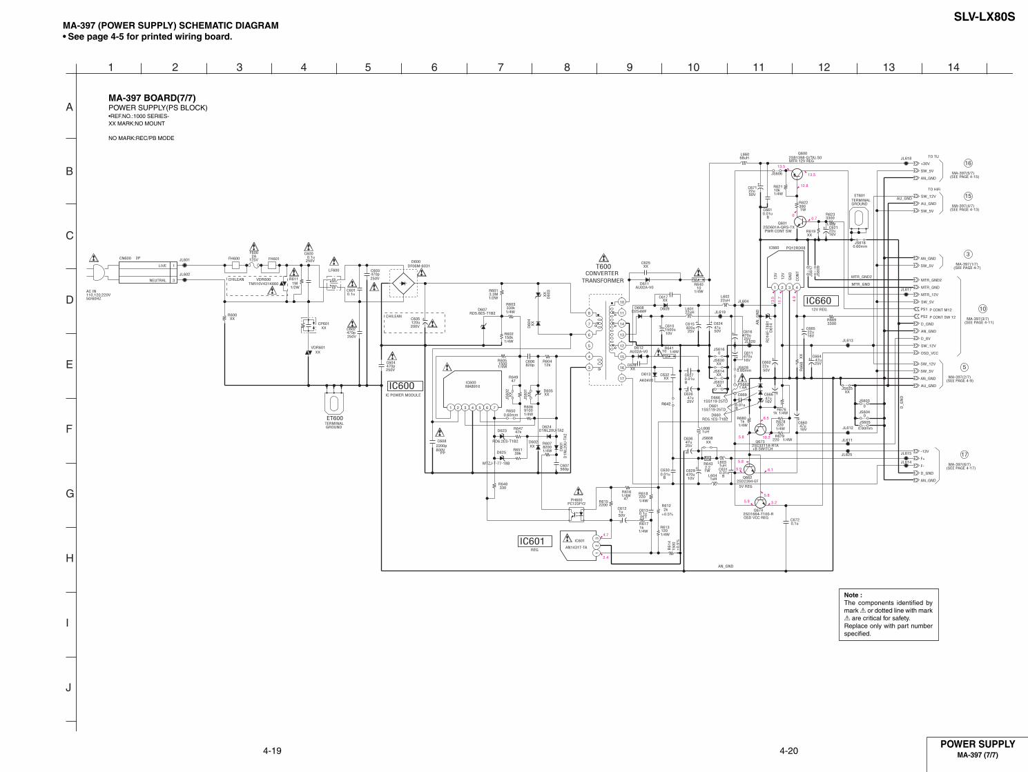
SLV-LX80S
A
1 2 3 4 5 6 7 8 9 10 11 12 13 14
B
C
D
E
F
G
H
I
J
4-19 4-20POWER SUPPLY
MA-397 (7/7)
Note :The components identified bymark ! or dotted line with mark! are critical for safety.Replace only with part numberspecified.
MA-397 BOARD(7/7)POWER SUPPLY(PS BLOCK)•REF.NO.:1000 SERIES-XX MARK:NO MOUNT
NO MARK:REC/PB MODE
MA-397 (POWER SUPPLY) SCHEMATIC DIAGRAM• See page 4-5 for printed wiring board.
SW_12V
1/4W330kR603
C6010.1u
XX
R66
8
AU_GND
560pC607
JL612
JL618
1/4W1kR617
250V470pC602
PQ12RD08IC660
1 2 3 4
C671
50V22u
D609
B0.01u
C669
0.60mm
JS605
1/4W8200R607
1/4W47
R616
Q6622SD2394-EF
MTR_GND
FH600
JL602
Q6742SD1664-T100-R
47u25V
C636
1SS119-25TDD666
16V22u
C665
±0.5%2k
R612
AN1431T-TA
IC601
12
3
0.60mmJS628
1/4W
3300R623
B0.01uC627
D623
RD6.2ES-T1B2
AN_GND
OSD_VCC
D1N
L20U
-TA
2D
601
C605
200V120u
22u16V
C621
JS60
9
XXD605
+30V
ET601
C6101500u10V
1W
R622390
PC123FY2PH600
R6432.21W
47u50V
C624
0.60mmR650
R679220 1/4W
SW_5V
RD5.1ES-T1B2D660
AU02A-V0D612
AN_GND
10R640
1/4W
0JS616
D608D2S4MF
1/4W
R678220
JL619
JS61
7
120R613
1/4W
JL615
XXJS630
XX
JS60
1
AU_GND
47kR647
XXC617
ET600
D_GND
330R648
1.6APS662
R6152200
D61
4R
D16
F-T8
B1
2PCN600
1
3
D602XX
B0.01uC661
VDR600TNR10V431K660
CHILEAN
MTZJ-T-77-18B
D625
1/4W1kR676
C615XX
D60
4
47R649
R65139k
1uHL604
JL601
1SS119-25TDD661
1uHL606
47u25V
C626
1uHL603
D_6V
-13V
XXJS614
MA8910IC600
1 2 3 4 5 6 7
Q6002SB1398-Q(TA).S0
JS6180.60mm
AU02A-V0D611
JL611
0JS604
MTR_GND2
XXR600
SW_12V
VDR601XX
1/4W1k
R680
AN_GND
C608
800VPP
2200p
LF600
125V2A
F600
68uHL660
1500
R61
4
±0.
5%
JL614
2201/4W
R618
AN_GND
JL625
12kR604
XXC625
XXJS631
D_GND
F-
2SD601A-QRS-TXQ601
1/2W3.3MR601
L60222uH
C6300.01u
B
JL613
0JS603
XXR619
1/4W
R602150k
R60515001/4W
250V470pC604
47u16V
C666
0.01uB
C631
XXJS625
2SC3311A-RTAQ673
XXC628
SW_5V
SW_5V
XXC632
C600
250V0.1u
47u16V
C660
FH601
RD5.6ES-T1B2D607
F+
JS606
JL620
JL604
AN_GND
3300R669
SW_5V
R64110 1/4W
470u10V
C629
22uHL601
250V470pC603
XXJS608
1/4W9100R606
1/4W10kR621
PS2
470u16V
C611
C6720.1u
AK04V0
D613
MTR_12V
470u25V
C616
JL617
C6130.1u
22u50V
C662820pC606
D1NL20U-TA2D624
50V1u
C612
CP601XX
PS1
SW_12V
XX
JS60
2
D600DF06M-6031
C664
25V47u
SW_5V
1MR611
1/2W
XX
D60
3
T600
3
4
6
7
8
10
11
14
13
12
15
16
17
5
R642
AU_GND
MTR_GND
D_G
ND
MTR_GND2
AN_GND
AN
_GN
D
LIVE
NEUTRAL
TO HiFi
P CONT M12
820u25V
CO
NT
P CONT SW 12
TO TU
13V
GN
D
12V
PET
AC IN 110,120,220V50/60HZ
CONVERTERTRANSFORMER
TERMINALGROUND
TERMINAL GROUND
IC600IC POWER MODULE
MTR 12V REG
PWR CONT SW
IC66012V REG
+B SWITCH
5V REG
OSD VCC REG
IC601REG
13.5
13.5
12.8
0.70
13.5
11.7 4.9
6.1
5.8
5.9
5.8
5.9 5.2
6.5
10.25.8
4.7
2.4
MA-397(6/7)(SEE PAGE 4-17)
MA-397(2/7)(SEE PAGE 4-9)
MA-397(3/7)(SEE PAGE 4-11)
MA-397(1/7)(SEE PAGE 4-7)
MA-397(4/7)(SEE PAGE 4-13)
MA-397(5/7)(SEE PAGE 4-15)
16
15
3
10
5
17
CHILEAN

SLV-LX80S
A
1 2 3 4 5 6 7 8 9 10 11 12 13 14
B
C
D
E
F
G
H
I
J
4-21 4-22
1 IC260 4 REC/PB
2 IC260 5 REC/PB
3 IC260 7 PB
3.6Vp-pV
3.5Vp-p
0.6Vp-p
4 IC260 9 REC
5 IC260 0 REC
6 IC260 qj REC
170mVp-p
380mVp-p
3.8Vp-p
0.1µsec/div50mV/div
0.1µsec/div1V/div
H
V
H
MA-397 BOARD (1/7)(R/P BLOCK)
0.1µsec/div0.1V/div
7 IC201 2 REC
8 IC201 7 REC
380mVp-p
360mVp-p
9 IC201 wd PB
0 IC201 wk REC/PB
qa IC201 wl REC
qa IC201 wl PB
qs IC201 ok
qd IC201 ej REC
qf IC201 yj REC/PB
qh T380 6 REC
qg IC201 1 PB
0.5Vp-pH
H 4.2Vp-p
2.1Vp-pH
2.3Vp-p
1.0Vp-p
R 460mVp-p
0.6Vp-p
1.6Vp-p
H
30Hz
H
3.579545MHzH
V
50Vp-p69.9kHz
RF SW PREC/PB
MA-397 BOARD (2/7)(VA BLOCK)
14.31818MHz
25.3MHz
qj IC160 el
qk IC160 rg
ql IC160 t; OSC V IN REC
ql IC160 t; OSC V IN PB
5.0Vp-p
4.6Vp-p
2.2Vp-p
2.3Vp-p
H
H
H
H
H
w; IC160 ts
w; IC160 ts OSD V OUT PB
wa IC160 th
2.2Vp-p
2.3Vp-p
OSC OUTREC/PB
ws IC160 ul S REEL
wd IC160 i;T REEL
wf IC160 ij CAP FG SP
wj IC160 og CTL+IN REC
wk IC160 oj
wl IC160 eh
wh IC160 o;
wg IC160 il
4.8Vp-p
4.8Vp-p
4.4Vp-p
4.5Vp-p
4.6Vp-p
5.0Vp-p
4.0Vp-p
3.0Vp-p
0.9sec (TAPE TOP)
1.6sec (TAPE TOP)
1078Hz
360Hz
30Hz
30Hz
30Hz
32.768kHz
4fsc (OUT)REC/PB
DRAM FGREC/PB
DRAM PGREC/PB
CTL AMP OUTPB
32kHz (OUT)REC/PB
OSD V OUTREC
C VIDEO INREC/PB
MA-397 BOARD (3/7)(SS BLOCK)
2.0Vp-p

SLV-LX80S
CNJ801
2 1 5 34 8 67
JL801
33R804
0.001uC805
XXJS801
S801
0R802
HZM6.8ZWA1TLD801
JL806
HZM6.8ZWA1TLD802
MA8
051-
TXD
803
JL807
0.001uC803
JL809
HZM6.8ZWA1TLD804
0R801
0.001uC806JL802
75R803
JL803
JL804
JL805
7PCN801
1POWER
2D_GND
3L2(R)
4AU_GND
5L2(L)
6AN_GND
7L2_VIDEO
RVIDEO L
POWER
AUDIO
VIDEO SIGNAL
REC
PB
CHROMA Y Y/CHROMA
AUDIOSIGNAL
MA-397(6/7) CN401(SEE PAGE 4-17)
FJ-28 (LINE 2 IN) PRINTED WIRING BOARD AND SCHEMATIC DIAGRAM— Ref. No. FJ-28 Board:2,000 Series —
A
1 2 3 4 5 6 7
B
C
D
FJ-28 BOARD
LINE-2 INFJ-28
VIDEO, AUDIO,SERVO/SYSTEM CONTROL,TUNER, POWER SUPPLY
FJ-28 (LINE 2 IN)
DI-81 (DIAL TIMER)
DM-98 (USER CONTROL)
MA-397
( )
There are few cases that the part printedon this diagram isn’t mounted in this model.
4-23
FJ-28 BOARDLINE 2 IN•REF.NO.:2000 SERIES-XX MARK:NO MOUNT

SLV-LX80S
JL468
S462
JL465
S466
S468
JL466
2200R470
S463
1500R469
S467
1500R468
2200R467
1500R465
S472
S469
JL467
33R474
CN4715P
D_GND 1
EJECT 2
CH- 3
PB/STOP 4
CH+ 5
JL469
1500R475
S481XX
S482XX
S483XX
S484XX
S485XX
EJECT
REC
REW
STOP
PLAY
FF
PAUSE
MA-397(6/7) CN403(SEE PAGE 4-18)
DM-98 (USER CONTROL) PRINTED WIRING BOARD AND SCHEMATIC DIAGRAM— Ref. No. DM-98 Board:2,000 Series —
DM-98 BOARD
A
1 2 3 4 5 6 7
B
C
D
VIDEO, AUDIO,SERVO/SYSTEM CONTROL,TUNER, POWER SUPPLY
FJ-28 (LINE 2 IN)
DI-81 (DIAL TIMER)
DM-98 (USER CONTROL)
MA-397
( )
There are few cases that the part printedon this diagram isn’t mounted in this model.
4-24
DM-98 BOARDUSER CONTROL•REF.NO.:2000 SERIES-
USER CONTROLDM-98

SLV-LX80S
VIDEO, AUDIO,SERVO/SYSTEM CONTROL,TUNER, POWER SUPPLY
FJ-28 (LINE 2 IN)
DI-81 (DIAL TIMER)
DM-98 (USER CONTROL)
MA-397
( )
DI-81 (DIAL TIMER) PRINTED WIRING BOARD AND SCHEMATIC DIAGRAM— Ref. No. DI-81 Board:1,000 Series —
DI-81 BOARD
A
1 2 3 4 5 6 7
B
C
D
DIAL TIMERDI-814-25E
There are few cases that the part printedon this diagram isn’t mounted in this model.
DI-81 BOARDDIAL TIMER•REF.NO.:1000 SERIES-
XXR901
JL901
JL904
JL902
S900
JL900
SLR-342DCT31D900
JL903
330
R902
JL905 S901
0
R900
CN9017P
D-GND 1
SEARCH LED 2
KKP+ 3
KKP- 4
DIAL 5
TIMER 6
GND 7
SEARCH
SEARCH
DIAL TIMER
PUSH/TURN
MA-397(6/7) CN404(SEE PAGE 4-17)

SLV-LX80S
5-1
5-1. SYSTEM CONTROL — MECHANISM BLOCK INTERFACE(MA-397 BOARD IC160)
*1 “L” When erasing protection tab is bent. “H” when not bent.*2 Pulse of period in proportion to reel rotating speed.*3 Approx. 2 msec period “H” pluse when tape top or end is detected.*4 Normally “L”. 2 msec period “H” puise when tape top or end is detected.*5 Hi-Z
Signal
CAM
MODE 1
MODE 2
MODE 3
MODE 4
REC PRF
T REEL
S REEL
END LED
T SENS
S SENS
Pin No.
MA-397 Board
IC160ed
MA-397 Board
IC160wl
MA-397 Board
IC160wk
MA-397 Board
IC160wj
MA-397 Board
IC160wh
MA-397 Board
IC160e;
MA-397 Board
IC160i;
MA-397 Board
IC160ul
MA-397 Board
IC160w;
MA-397 Board
IC1607
MA-397 Board
IC1606
I/O
O
I
I
I
I
I
I
I
O
I
I
EJECTED
*5
—
—
—
—
L
H/L
H/L
L
*3
*3
CASSETTELOARDING
H
—
—
—
—
*1
H/L
H/L
*3
*3
*3
CASSETTEUNLOARDING
L
—
—
—
—
*1
H/L
H/L
*3
*3
*3
TAPETHREADING
H
—
—
—
—
*1
H/L
*2
*3
*4
*4
TAPEUNTEREADING
L
—
—
—
—
*1
H/L
*2
*3
*4
*4
STOP
*5
H
L
H
H
*1
H/L
H/L
*3
*4
*4
REW
*5
H
L
H
L
*1
*2
*2
*3
*4
*4
FF
*5
H
L
H
L
*1
*2
*2
*3
*4
*4
PB
*5
H
H
L
L
*1
*2
*2
*3
*4
*4
REC
*5
H
H
L
L
*1
*2
*2
*3
*4
*4
5-2. SYSTEM CONTROL — SERVO PERIPHERAL CIRCUIT INTERFACE(MA-397 BOARD IC160)
*1. 30Hz pulse.*2. Pulse of period in propotion to tape speed.*3. 30Hz “H” pluse.*4. 720 Hz pulse.*5. Unstable period pulse.*6. DC voltage 1 – 5V.*7. Hi-Z (2.5V)
Signal
CTL IN+
DRUM PG
DRUM FG
CAP FG
CAP RVS
CAP ERR
DRUM ERR
Pin No.
MA-397 Board
IC160og
MA-397 Board
IC160o;
MA-397 Board
IC160il
MA-397 Board
IC160ij
MA-397 Board
IC160ef
MA-397 Board
IC160uh
MA-397 Board
IC160uj
I/O
O
I
I
I
O
O
O
TAPETHREADING
*7
*3
*4
*5
L
*6
*6
TAPEUNTEREADING
*7
*3
*4
*5
H
*6
*6
STOP
*7
*3
*4
H/L
H/L
L
*6
REW
*7
*3
*4
*2
H
*6
*6
FF
*7
*3
*4
*2
L
*6
*6
PB
*7
*3
*4
*2
L
*6
*6
REC
*1
*3
*4
*2
L
*6
*6
SECTION 5INTERFACE, IC PIN FUNCTION DESCRIPTION

5-2
5-3. SYSTEM CONTROL — SYSTEM CONTROL PERIPHERAL CIRCUIT INTERFACE (MA-397 BOARD IC160)
5-4. SYSTEM CONTROL AND RF MODULATOR — INPUT SELECTION BLOCK INTERFACE(MA-397 BOARD IC160)
Signal
ANT SEL
Pin No.MA-397 Board
IC160wa
I/O
O
I/O level
“H” when RF modulator through.
5-5. SYSTEM CONTROL — VIDEO/RP BLOCK INTERFACE (MA-397 BOARD IC160)
Signal
RF SWP
QVD
C SYNC
Pin No.
MA-397 BoardIC160qk
MA-397 BoardIC160qd
MA-397 BoardIC160tk
TAPELOADING
*1
L
*3
TAPEUNLOADING
*1
L
*3
STOP/FF/REW
*1
L
*3
PB
*1
*2
*3
REC
*1
L
*3
I/O
O
O
I
REC/PAUSE
*1
L
*3
*1. Synchronized with drum rocation, 30Hz 50% duty pulse.*2. Normal “L”, “H” when video signal is not rgenerated.*3. Composite sync signal (positive).
5-6. SYSTEM CONTROL — AUDIO BLOCK INTERFACE (MA-397 BOARD IC160)
Signal
A MUTE
AF REC P
Pin No.
MA-397 BoardIC160yd
MA-397 BoardIC160ws
TAPELOADING
L
L
TAPEUNLOADING
L
L
STOP/FF/REW
L
L
PB
L
L
REC
L
H
I/O
O
O
REC/PAUSE
L
L
Signal
RESET
I2C DATA 1
I2C CLOCK 1
I2C DATA VIDEO
I2C CLOCK VIDEO
(ARC) S OUT 1
(ARC) CLK 1
Pin No.MA-397 Board
IC160efMA-397 Board
IC160esMA-397 Board
IC160eaMA-397 Board
IC160usMA-397 Board
IC160uaMA-397 Board
IC160rsMA-397 Board
IC160ra
I/O
I
I/O
O
I/O
O
I/O
O
I/O level
Normally “H”, “L” when service interruption detected or restored.
Serial communication data to EEPROM I2C161.
Serial communication clock to EEPROM I2C161.
Serial communication data to video and audio microprocessor.
Serial communication clock to video and audio microprocessor.
Serial communication data to ARC microprocessor.
Serial communication clock to ARC microprocessor.

5-3
5-7. SERVO/SYSTEM CONTROL MICROPROCESSOR PIN FUNCTIONS(MA-397 BOARD IC160)
Pin No.
1
2
3
4
5
6
7
8
9
10
11
12
13
14
15
16
17
18
19
20
21
22
23
24
25
26
27
28
29
30
31
32
33
34
35
36
37
38
39
40
41
42
43
44
45
46
47
48
49
50
Pin Name
DEST
FULL ERS
TU AFT
FUNC KEY2
FUNC KEY1
S SENS
T SENS
V RF ENV
AF ANV
CBC ON
KKP+
KKP–
QVD
REMOCON
C ROT
HA SWP
ENV SW
RF SWP
AF SWP
END LED
ANT SEL
AF REC P
FE ON
CAP RVS
SUR ON
MODE4
MODE3
MODE2
MODE1
REC PRF
I2C CLK EEP
I2C DATA EEP
CAM
RESET
32kHz (in)
32kHz (out)
Vcc
4fsc (in)
4fsc (out)
Vss
ARC CLK
ARC DATA
CLK SEL
OSC IN
OSC OUT
NUB
LPF
SP
OSD GND
OSD V IN
I/O
I
I
I
I
I
I
I
I
I
O
I
I
O
I
O
O
I
O
O
O
O
O
—
O
—
I
I
I
I
I
I/O
I/O
O
I
I
O
I
I
O
—
O
O
I
I
O
—
I/O
O
—
I
Function
Destination control input
STEREO/MONO/SAP DETECTION
Tuner analog AFT input
Key input
Key input
Tape end sensor input
Tape top sensor input
Video playback signal envelope input
Hi-Fi audio playback signal envelope input
Cable box control signal output
ETR pulese signal input
ETR pulese signal input
Quasi VD pulese output
Remote sires signal input
Head AZ signal output
SP/EP changed head signal
SP/EP head output lebel ditaction signal
VIDEO RF switching pulse output.
AF switching pulse output.
END sensor LED output
TV/VTR RF modulator control output
Hi-Fi record control pulse output.
NC
Capstan reverse control
NC
Mechanism section CAM encoder input (data4)
Mechanism section CAM encoder input (data3)
Mechanism section CAM encoder input (data2)
Mechanism section CAM encoder input (data1)
Erasing protection tab, cassette IN detection input
HC CLOCK line (EEPROM)
HC DATA line (EEPROM)
Cam motor control signal output
System reset input
Sub clock 32MHz
Sub clock 32MHz
5V
Main clock input
Main clock output
Ground
Realityregenarator (ARC) control clock signal
Realityregenarator (ARC) control data signal
CLOCK seleal “L” Sub clock, “H” main and sub clock.
OSD clock input
OSD clock output
Ground
fsc filter
“L” output when SP mode.
Ground
OSD Video signal input.
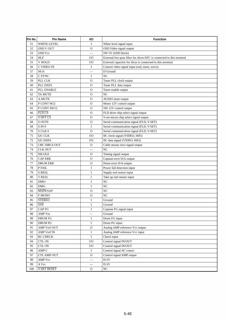
Pin No.
51
52
53
54
55
56
57
58
59
60
61
62
63
64
65
66
67
68
69
70
71
72
73
74
75
76
77
78
79
80
81
82
83
84
85
86
87
88
89
90
91
92
93
94
95
96
97
98
99
100
Pin Name
WHITE LEVEL
OSD V OUT
OSD Vcc
HLF
V HOLD
C VIDEO IN
NUA
C SYNC
PLL CLK
PLL DATA
PLL ENABLE
TA MUTE
A MUTE
P CONT M12
P CONT SW12
FLD CS
V-SET CS
S OUT0
S IN 0
S CLK 0
I2C CLK
I2C DATA
CBC SIRCS OUT
CLK OUT
NICOLE
CAP ERR
DRUM ERR
P FAIL
S REEL
T REEL
DMS+
DMS–
MAIN/SAP
F MONO
STEREO
SAP
CAP FG
AMP Vss
DRUM FG
DRUM PG
AMP Vref OUT
AMP Vref IN
RC CHECK
CTL–IN
CTL+IN
AMP C
CTL AMP OUT
AMP Vcc
A Vcc
V-SET RESET
I/O
I
O
—
I/O
I/O
I
—
I
O
O
O
O
O
O
O
O
O
O
I
O
I/O
I/O
O
—
O
O
O
I
I
I
I
I
O
O
I
I
I
—
I
I
O
I
I
I/O
I/O
I
O
—
—
O
Function
White level signal input
OSD Video signal output
SW 5V (OSD block)
External low-pass filter for slicer/AFC is connected to this terminal
External capacitor for slicer is connected to this terminal
Control video signal input (osd, tuner, sorvo)
D Ground
NC
Tuner PLL clock output
Tuner PLL data output
Tuner enable output
NC
AUDIO mute output
Motor 12V control output
SW 12V control output
FLD drive chip select signal output
V-set micon chip select signal output
Serial communication signal (FLD, V-SET)
Serial communication signal (FLD, V-SET)
Serial communication signal (FLD, V-SET)
IIC clock signal (VIDEO, HiFi)
IIC data signal (VIDEO, HiFi)
Cable mouse sircs signal output
NC
Timing signal output
Capstan error D/A output
Drum error D/A output
Power fail detection input
Supply reel sensor input
Take up reel sensor input
NC
NC
NC
NC
Ground
Ground
Capstan FG signal input
Ground
Drum FG input.
Drum PG input.
Analog AMP reference Vcc output
Analog AMP reference Vcc input
Check input
Control signal IN/OUT
Control signal IN/OUT
Control signal AC conect
Control signal AMP output
D-5V
D-5V
NC
5-4E

SLV-LX80S
6-1
6-1 MECHANICAL ADJUSTMENTS
For the mechanical adjustments, please refer to the“VHS MECHANICAL ADJUSTMENT MANUAL(S MECHANISM)” (9-921-647-11).
6-2. ELECTRICAL ADJUSTMENTS
See the adjusting part location diagram from on page 6-6for the adjustment.
2-1. PREPARATION BEFORE ADJUSTMENT2-1-1. Equipment RequiredThe measuring instruments used for this alignment include:1) Monitor TV2) Oscilloscope, dual-trace, bandwidth of 30 MHz or more, with
delay mode (A probe 10:1 should be used unless otherwisespecified.)
3) Frequency counter4) NTSC Pattern generator5) Remote commander6) Digital voltmeter7) Audio generator8) Audio level meter9) Audio attenuator10) Alignment tapes
KRV-51N2 (NTSC) Part No. : 8-192-605-32
2-1-2. Equipment ConnectionUnless otherwise specified, connect and adjust the measuringinstruments as shown in the following diagram.
Fig. 6-2-1
2-1-3. Set-up of AdjustmentIn this adjustment, NTSC pattern generator is connected with LINEinput terminal. When check to tuner, connected AERIAL terminal.Check that the synchronizing signal of the Y signal has an amplitudeof approximately 0.7 V and that the burst signal has an amplitude ofapproximately 0.3 V and its waveform is flat. And check that thelevel ratio of burst signal to “red” signal is 0.30 : 0.66. The videosignal (color bar) used for electrical aligning this unit is shown inFig. 6-2-2.
NTSC model
Fig. 6-2-2 Color Bar Signals of Pattern Generator
2-1-4. Alignment Tape• Contents of KRV-51N2
VIDEO LINE IN
VIDEO LINE OUTVideo output(75Ω)
Pattern generator VCR Monitor TV
1
2
3
4
Mode
SP
LP
Period
7 minutes
3 minutes
7 minutes
3 minutes
Video signal
Color bar
Monoscope
Color bar
Monoscope
Audio signalHi-Fi
400Hz
(L/R)
Normal
400Hz
White (100%)
About 0.7 V
About 0.3 V
Horizontal sync signalRed Burst signal
(It must be flat.)
About 0.3 V
SECTION 6ADJUSTMENTS
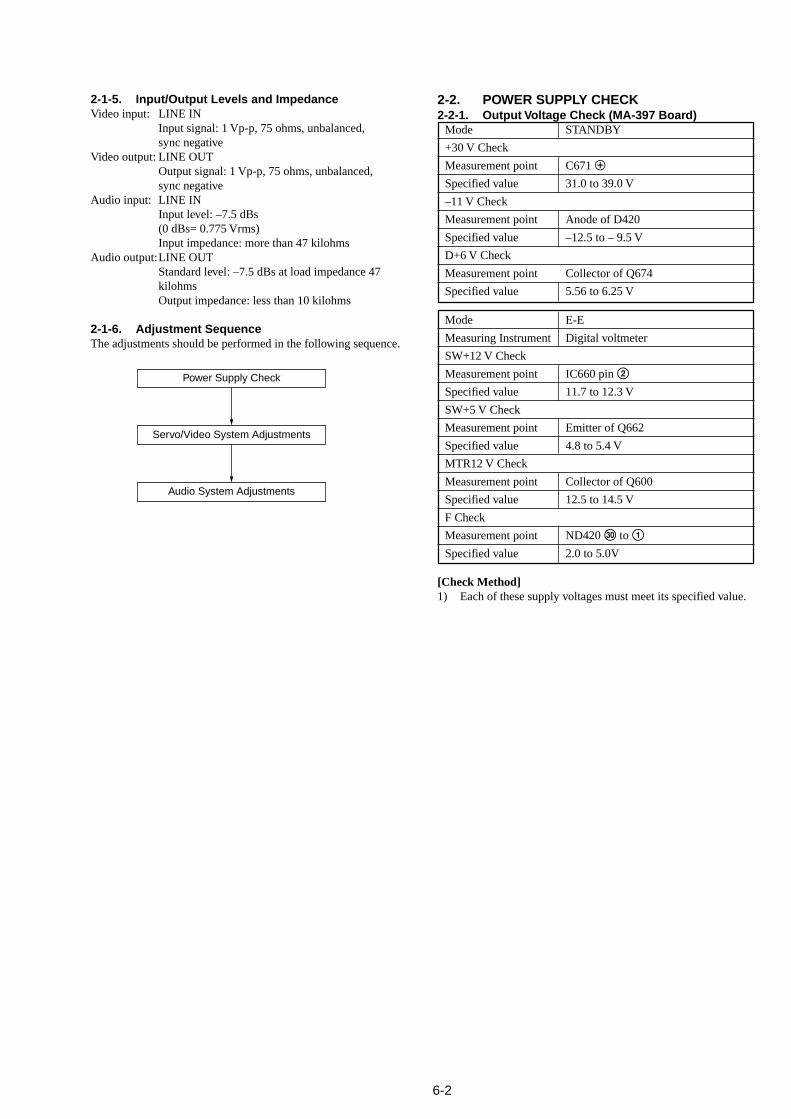
6-2
2-1-5. Input/Output Levels and ImpedanceVideo input: LINE IN
Input signal: 1 Vp-p, 75 ohms, unbalanced,sync negative
Video output: LINE OUTOutput signal: 1 Vp-p, 75 ohms, unbalanced,sync negative
Audio input: LINE INInput level: –7.5 dBs(0 dBs= 0.775 Vrms)Input impedance: more than 47 kilohms
Audio output:LINE OUTStandard level: –7.5 dBs at load impedance 47kilohmsOutput impedance: less than 10 kilohms
2-1-6. Adjustment SequenceThe adjustments should be performed in the following sequence.
2-2. POWER SUPPLY CHECK2-2-1. Output Voltage Check (MA-397 Board)
Mode STANDBY
+30 V Check
Measurement point C671 3
Specified value 31.0 to 39.0 V
–11 V Check
Measurement point Anode of D420
Specified value –12.5 to – 9.5 V
D+6 V Check
Measurement point Collector of Q674
Specified value 5.56 to 6.25 V
Mode E-E
Measuring Instrument Digital voltmeter
SW+12 V Check
Measurement point IC660 pin 2
Specified value 11.7 to 12.3 V
SW+5 V Check
Measurement point Emitter of Q662
Specified value 4.8 to 5.4 V
MTR12 V Check
Measurement point Collector of Q600
Specified value 12.5 to 14.5 V
F Check
Measurement point ND420 e; to 1
Specified value 2.0 to 5.0V
[Check Method]1) Each of these supply voltages must meet its specified value.
Power Supply Check
Servo/Video System Adjustments
Audio System Adjustments

6-3
2-3. SERVO SYSTEM CHECK2-3-1. RF Switching Position Adjustment
(MA-397 Board)[Adjustment Purpose]To adjust the link of the A-ch and B-ch of the tape playback outputs.To make the unit compatible with other tapes and units. If thisspecification is not satisfied, the link will appear on the screen andthe screen will be disrupted, etc.
Mode Playback
Signal Alignment tape: SP color bar portion
Measurement point CH1: CN270 pin 2 (PB RF)CH2: CN270 pin 3 (RF SWP)
Measuring instrument Oscilloscope
Adjusting element Remote Commander CH+/–
Specified value A=minimize
[Adjustment Method]1) Playback the alignment tape.2) Short JS401 to Ground.3) Check that “A P” is indicated on FL display.4) Adjust so that part A becomes minimized at CH +/–.5) Write data in EEPROM by pressing PAUSE button.Monoral model:6) The display “A P” disappears and then the Adjustment mode
terminates.Hi-Fi model:6) The display changes to “A H” and the mode goes to the HiFi
switching position Adjustment.(2-4-2.)
Fig. 6-2-3
2-4. AUDIO SYSTEM ADJUSTMENT• Adjust both L ch and R ch.[Connecting Instruments]
Fig. 6-2-4
2-4-1. Hi-Fi Audio System Adjustment(Hi-Fi model only)
• Perform the adjustment setting the switch on the followingpositions.
• AUDIO MONITOR STEREO
[Adjustment Method]1. ACE head adjustment.....Refer to the VHS mechanical
adjustment manual (S MECHANISM)(9-921-647-11).2. E-E output level check3. “Recording Bias Adjustment”
Audio line OUTPUT L/R
Audio line INPUT L/R
Audio oscillator
Attenuator
600 Ω
Audio level meter or distortion meter
47 kΩ
VTR
CH1PB RF
CH2RF SWP
A

6-4
2-4-3. Normal Audio System Adjustment• Make adjustment in the SP mode unless otherwise specified. Use
a normal VHS cassette for an adjustment tape.• Set AUDIO MONITOR to normal.
2-4-4. Audio Level and Distortion Check[Adjustment purpose]Confirm that the audio level and distortion is within the specification.
Mode REC and PB (SP mode)
Signal 400 Hz, –7.5 dBs
Measurement point Audio output terminal
Measuring instrument Audio level meter and distortionmeter
Specified value PB level : –7.5±2dBs (HIFI)PB level : –7.5±3dBs (MONO)Distortion : less than 1% (HIFI)Distortion : less than 4% (MONO)
[Confirmation Method]1) Supply a signal of 400 Hz, –7.5 dBs to both L and R channels
of Audio Line Input.2) Record the tape.3) Playback a recorded portion of the tape.4) Confirm that the playback output level of audio level meter is
within of range –7.5±2dBs for HIFI and –7.5±3dBs for MONO.5) Confirm that the output of distortion meter is less than 1% for
HIFI and 4% for MONO.
2-4-2. HiFi Switching Position Adjustment(MA-397 Board)
[Adjustment Purpose]To adjust the link of the A-ch and B-ch of the tape playback outputs.To make the unit compatible with other tapes and units. If thisspecification is not satisfied, the link will appear on the screen andthe screen will be disrupted, etc.
Mode Playback
Signal Alignment tape: SP color bar portion
Measurement point CH1: Pin 1 of CN270 (HF ADJ)CH2: Pin 3 of CN270 (RF SWP)
Measuring instrument Oscilloscope
Adjusting element Remote Commander CH +/–
Specified value B=minimize
[Adjustment Method]1) Check that “A H” is indicated on FL display.2) Adjust so that part B becomes minimized at CH +/–.3) Write data EEPROM by pressing PAUSE button.4) Check that “A H” indicator turns off.5) If “A H” indicator is still on, restart RF switching position
Adjustment from the beginning.
Fig. 6-2-5
CH1HFADJ
CH2RF SWP
B
2-4-5. Audio Noise Check[Adjustment purpose]Confirm that the noise level is within the specification.
Mode REC and PB (SP mode)
Signal No signal input
Measurement point Audio output terminal
Measuring instrument Audio level meter
Specified value Less than –67,5dBs (HIFI)Less than –45.5dBs (MONO)
[Confirmation method]1) Audio line input L and R channels are shorted to the ground.2) Record the tape.3) Playback a recorded portion of the tape.4) Confirm that the output level is less than –67.5dBs for HIFI
and –45.5dBs for MONO.
2-4-6. ACE Head AdjustmentRefer to the VHS mechanical adjustment manual (SMECHANISM) (9-921-647-11).
2-4-7. E-E Output Level Check[Adjustment purpose]Confirm that the output level adjust the reference input is within thespecification.
Mode E-E
Signal 400 Hz, –7.5 dBs
Measurement point CNJ561 L/R
Measuring instrument Audio level meter
Specified value –7.5 ± 2 dBs
[Check Method]1) Input signal of 400 Hz and –7.5 dBs to the CNJ561 L/R.2) Check that the audio output level is –7.5 ± 2 dBs.
2-4-8. Frequency Response Check[Adjustment purpose]Confirm that the frequency characteristic is within the specification.
Mode REC and PB (SP mode)
Signal 400 Hz, –17.5 dBs7 kHz, –17.5 dBs
Measurement point CNJ561 L/R
Measuring instrument Audio level meter
Specified value 0 ± 3 dB
Note: Tape path adjustment must have been completed.
[Confirmation Method]1) Supply a signal of 400 Hz, –17.5 dBs to CNJ561 L/R.2) Connect the audio level meter to CNJ561 L/R.3) Adjust the attenuator so that the audio level meter will indicate
–17.5 dBs.4) Make recording in the SP mode.5) Set an audio line input signal to 7 kHz and make recording.6) Playback a recorded portion, and measure output levels at 400
Hz and 7 kHz.7) Confirm that the 7 kHz playback output level within a range of
the 400 Hz playback output level 0 ± 3 dB.

SLV-LX80S
2-5. ADJUSTING PARTS LOCATION DIAGRAM
MA-397 BOARD(CONDUCTOR SIDE)
CNJ561
VIDEO/AUDIO LINEIN/OUT
CN270
RF/HF SWP
4 1
Q600
Q674
C671
+30 V
+12VD420-11V
+6VSW5V
MTR12 V
B E
B
E
+
14
IC660JS401ADJ
130 ND420
6-5E

SLV-LX80S
7-1
SECTION 7REPAIR PARTS LIST
7-1. EXPLODED VIEWSNOTE:• -XX, -X mean standardized parts, so they may
have some differences from the original one.• Items marked “*” are not stocked since they
are seldom required for routine service. Somedelay should be anticipated when ordering theseitems.
• The mechanical parts with no reference numberin the exploded views are not supplied.
The components identified by mark ! ordotted line with mark ! are critical for safety.Replace only with part number specified.
Les composants identifiés par une marque! sont critiques pour la sécurité.Ne les remplacer que par une pièce portantle numéro spécifié.7-1-1. FRONT PANEL AND UPPER CASE SECTION
Ref. No. Part No. Description Remarks Ref. No. Part No. Description Remarks
1
14
2
34
4
415
56
78
9 10
11
12
12
13
8
1 X-3950-018-1 PANEL ASSY, FRONT2 3-953-432-01 SPRING (GE), FL3 3-058-039-11 DOOR,CASSETTE4 4-921-277-41 SCREW (B2.6 x 8), TAPPING, BIND
* 5 A-6794-718-A DM-98 MOUNT
6 1-757-552-12 FLAT CABLE FDM-010* 7 A-6794-730-A DI-81 MOUNT
8 1-757-553-11 FLAT CABLE FDI-002
* 9 A-6794-717-A FJ-28 MOUNT! 10 1-782-000-33 CORD, POWER (Chilean)! 10 1-777-852-33 CORD, POWER (Mexican)* 11 3-057-168-41 CASE, UPPER
12 3-710-901-61 SCREW, TAPPING
* 13 1-418-698-11 COMMANDER, STANDARD (RMT-V294A)14 3-943-995-31 EMBLEM (NO.5), SONY15 3-057-165-01 PLATE,EARTH
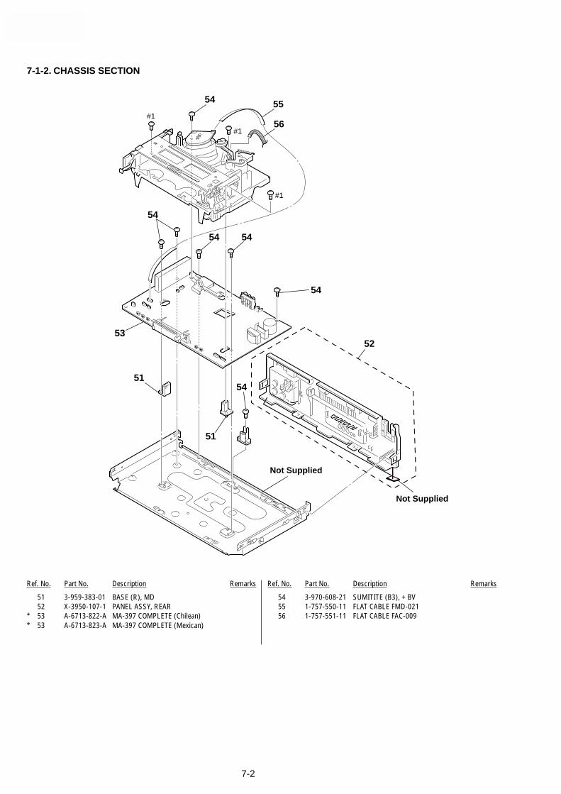
SLV-LX80S
7-2
51
52
51
Not Supplied
Not Supplied
#1
#1
#1
53
54
54
54
54
54 55
54
56
7-1-2. CHASSIS SECTION
Ref. No. Part No. Description Remarks Ref. No. Part No. Description Remarks
51 3-959-383-01 BASE (R), MD52 X-3950-107-1 PANEL ASSY, REAR
* 53 A-6713-822-A MA-397 COMPLETE (Chilean)* 53 A-6713-823-A MA-397 COMPLETE (Mexican)
54 3-970-608-21 SUMITITE (B3), + BV55 1-757-550-11 FLAT CABLE FMD-02156 1-757-551-11 FLAT CABLE FAC-009

SLV-LX80S
7-3
7-1-3. MECHANISM DECK SECTION-1
701
702703
704710
705
723
722720
724
725
721
706
707
712
711
713
714
715
716
717
719
718
709
708
701
#2
Ref. No. Part No. Description Remarks Ref. No. Part No. Description Remarks
701 3-977-509-01 WASHER, THRUST702 3-977-507-01 TABLE, REEL (S)703 3-977-508-01 TABLE, REEL (T)704 1-500-471-11 HEAD, FE705 3-977-495-01 SHAFT, TG2
706 3-977-494-01 HOLDER, FEH707 A-6776-359-C FL, COMPLETE ASSY (SL)708 3-977-535-01 PLATE, LUMINOUS (END SENSOR)709 3-977-536-01 PLATE, LUMINOUS (TOP SENSOR)710 3-977-443-01 WASHER, STOPPER
711 A-6759-863-B PRESS BLOCK ASSY, PINCH712 3-958-455-01 SPRING (PINCH), TENSION713 3-977-447-01 GEAR, ELEVATOR
714 3-063-773-02 OPENER, LID (SL)715 3-977-441-03 GEAR, PINCH PRESSING716 3-977-445-02 GEAR, TG8 ARM DRIVING717 3-062-763-01 SPRING, EXTENSION (RVS BRAKE)718 X-3950-964-1 ARM ASSY, RVS BRAKE (SL)
719 3-063-756-01 GEAR, TG8 ARM720 X-3947-590-1 TG8 ASSY721 A-6759-620-A HEAD BLOCK ASSY, ACE722 3-974-556-11 + HEXA TT 2.6 x 9 (TAPER)723 3-979-508-01 SCREW + HEXA TP SW 3 x 8
724 3-059-958-01 SPRING, TG8725 3-051-300-03 LOCK ACE SCREW#2 7-685-646-79 SCREW + BVTP 3 x 8 TYPE2 IT-3

SLV-LX80S
7-4
770
772
763
765
768
767
769
761
757
756766
755
754752
751
753
759
763762
760
758771
#2
#3
764
7-1-4. MECHANISM DECK SECTION-2
Ref. No. Part No. Description Remarks Ref. No. Part No. Description Remarks
751 X-3947-581-4 BRAKE ASSY,MAIN(T)752 3-977-462-01 SPRING,EXTENTION. (MAIN BRAKE)753 X-3947-573-1 ARM ASSY, PENDULUM754 X-3947-580-5 BRAKE ASSY, MAIN(S)755 3-063-772-01 LEVER, REC PROOF
756 3-976-767-01 SPRING, TENS. (REC PROOF)757 3-977-487-01 BOSS, TG1 FULCRUM758 X-3950-966-1 TG1 ASSY (SL)759 3-063-958-01 SPRING,COMP(SL PEND)760 3-977-488-01 SPRING (POWER TENSION)
761 A-6775-922-A SHUTTLE (S) BLOCK ASSY (BRACKET)762 X-3948-050-1 ROLLER ASSY GUIDE
763 3-965-178-01 SPRING764 3-062-687-01 BASE DRUM, K (UPPER MOTOR)765 A-6750-328-E SHUTTLE (T) BLOCK ASSY766 3-977-501-01 PLATE, LUMINOUS767 A-6746-074-G ROLLER BLOCK ASSY, HC
768 X-3947-255-1 ROLLER ASSY, HC769 3-975-724-07 ARM, HC770 1-772-366-11 DRUM ASSY, DZH-OB7A-R771 X-3950-968-1 BAND, ASSY TG1 (SL)772 X-3949-910-1 G. ROLLER ASSY
#2 7-685-646-79 SCREW + BCTP 3 x 8 TYPE IT-3#3 7-682-647-09 SCREW + P3 x 6

SLV-LX80S
7-5
820
821
822
823824
801
804 806
808
807
813
827
828825
814
803
815
809
810
811
812
802
803
805
817
818
803816
819
#4
#2
826
M902
M903
not supplied
Ref. No. Part No. Description Remarks Ref. No. Part No. Description Remarks
801 3-977-437-01 RETAINER, CAM MOTOR802 X-3947-584-1 ASSY, REEL DIRECT803 3-977-443-01 WASHER, STOPPER804 3-063-760-01 WORM - WHEEL805 3-056-952-11 WASHER, STOPPER
806 3-977-444-01 GEAR, PINCH TRANSMISSION807 3-977-515-01 GUIDE, FL SLIDER808 3-977-517-01 PLATE, SLIDE, FL809 3-977-519-01 SPRING, TENS. (LIMIT, FL)810 3-977-518-02 PLATE, LIMITTER, FL
811 3-977-516-01 HOLDER, FL SLIDER812 3-977-877-01 PLATE, RETAINER813 3-977-504-01 GEAR, CLUTCH814 X-3947-585-1 GEAR, ASSY, PULLEY815 3-977-510-01 BELT RUBBER
816 3-056-824-01 WASHER, STOPPER
817 3-063-755-01 GEAR, CAM818 3-977-442-03 SLIDER819 3-063-757-01 GEAR, LOADING(T)820 3-977-456-03 SPRING, TORSION (LOAD T)821 X-3948-132-2 LEVER ASSY, LOADING(T)
822 3-977-451-01 GEAR, LOADING(S)823 3-977-452-01 SPRING, TORSION (LOAD S)824 X-3948-131-1 LEVER ASSY LOADING (S)825 3-977-489-01 ARM, TG1 DRIVING826 3-977-506-01 ARM, LIMITTER SELECTION
827 3-977-467-02 SPRING, CAP BRAKE828 X-3950-965-1 BRAKE ASSY, CAPSTAN (SL)M902 1-698-971-11 MOTOR, DCM903 X-3947-577-1 MOTOR ASSY, CAM#2 7-685-646-79 SCREW + BVTP 3 x 8 TYPE IT-3
#4 7-685-133-19 SCREW + P2.6 x 6 TYPE2 NON-SLIT
7-1-5. MECHANISM DECK SECTION-3

SLV-LX80S
7-6
Ref. No. Part No. Description Remarks Ref. No. Part No. Description Remarks7-2. ELECTRICAL PARTS LIST
A-6713-824-A DI-81 COMPLETE**************
<CONNECTOR>
CN901 1-695-368-31 CONNECTOR, FFC/FPC 7P
<DIODE>
D900 8-719-056-06 DIODE SLR-342DCT31
<RESISTOR>
R900 1-216-295-00 SHORT 0R902 1-216-037-00 RES-CHIP 330 5% 1/10W
<SWITCH>
S900 1-762-196-21 SWITCH, TACTS901 1-418-156-11 ENCODER, ROTARY
A-6713-820-A DM-98 COMPLETE***************
<CONNECTOR>
CN471 1-770-514-31 CONNECTOR, FFC/FPC 5P
<CHIP CONDUCTOR>
JR461 1-216-295-00 SHORT 0
<RESISTOR>
R465 1-216-053-00 RES-CHIP 1.5K 5% 1/10WR467 1-216-057-00 RES-CHIP 2.2K 5% 1/10WR468 1-216-053-00 RES-CHIP 1.5K 5% 1/10WR469 1-216-053-00 RES-CHIP 1.5K 5% 1/10WR470 1-216-057-00 RES-CHIP 2.2K 5% 1/10W
R474 1-216-013-00 RES-CHIP 33 5% 1/10WR475 1-216-053-00 RES-CHIP 1.5K 5% 1/10W
<SWITCH>
S462 1-762-196-21 SWITCH, TACT (6 EJECT)S463 1-762-196-21 SWITCH, TACT (r REC)S466 1-762-196-21 SWITCH, TACT (0 REW)S467 1-762-196-21 SWITCH, TACT (p STOP)S468 1-762-196-21 SWITCH, TACT (” PLAY)
S469 1-762-196-21 SWITCH, TACT () FF)S472 1-762-196-21 SWITCH, TACT (P PAUSE)
A-6713-819-A FJ-28 COMPLETE**************
<CAPACITOR>
C803 1-163-009-11 CERAMIC CHIP 0.001µF 10% 50VC805 1-163-009-11 CERAMIC CHIP 0.001µF 10% 50VC806 1-163-009-11 CERAMIC CHIP 0.001µF 10% 50V
<CONNECTOR>
CN801 1-695-368-31 CONNECTOR, FFC/FPC 7P
<JACK>
CNJ801 1-770-021-11 JACK, PIN 3P
<DIODE>
D801 8-719-071-15 DIODE HZM6.8ZWA1TLD802 8-719-071-15 DIODE HZM6.8ZWA1TLD803 8-719-422-37 DIODE MA8051-TXD804 8-719-071-15 DIODE HZM6.8ZWA1TL
<CHIP CONDUCTOR>
JR801 1-216-296-00 SHORT 0JR802 1-216-295-00 SHORT 0
<RESISTOR>
R801 1-216-295-00 SHORT 0R802 1-216-295-00 SHORT 0
DI-81 DM-98 FJ-28
Ref. No. Part No. Description Remarks Ref. No. Part No. Description Remarks
NOTE:• Due to standardization, replacements in the
parts list may be different from the partsspecified in the diagrams or the componentsused on the set.
• -XX, -X mean standardized parts, so they mayhave some difference from the original one.
• Items marked “*” are not stocked since theyare seldom required for routine service. Somedelay should be anticipated when ordering theseitems.
• CAPACITORS:uF: µF
• RESISTORSAll resistors are in ohms.METAL: metal-film resistorMETAL OXIDE: Metal Oxide-film resistorF: nonflammable
• COILSuH: µH
• SEMICONDUCTORSIn each case, u: µ, for example:uA...: µA... , uPA... , µPA... ,uPB... , µPB... , uPC... , µPC... ,uPD..., µPD...
When indicating parts by reference number,please include the board name.
The components identified by mark ! ordotted line with mark ! are critical for safety.Replace only with part number specified.

SLV-LX80S
7-7
Ref. No. Part No. Description Remarks Ref. No. Part No. Description Remarks
MA-397FJ-28
R803 1-216-022-00 RES-CHIP 75 5% 1/10WR804 1-216-013-00 RES-CHIP 33 5% 1/10W
<SWITCH>
S801 1-762-196-21 SWITCH, TACT
* A-6712-822-A MA-397 MOUNT (CHILEAN)* A-6712-823-A MA-397 MOUNT (MEXICAN)
***********************
A-6713-822-A MA-397 COMPL (CHILEAN)A-6713-823-A MA-397 COMPL (MEXICAN)3-065-631-01 INSULATOR (PS) (CHILEAN)3-064-645-01 HOLDER, FL (MEXICAN)3-960-273-11 SPACER, TOP END
* 3-960-274-01 SPACER, LED
<CAPACITOR>
C101 1-163-009-11 CERAMIC CHIP 0.001µF 10% 50VC102 1-163-009-11 CERAMIC CHIP 0.001µF 10% 50VC103 1-163-009-11 CERAMIC CHIP 0.001µF 10% 50VC104 1-163-009-11 CERAMIC CHIP 0.001µF 10% 50VC105 1-128-057-11 ELECT 330µF 20% 6.3V
C106 1-124-589-11 ELECT 47µF 20% 16VC107 1-164-346-11 CERAMIC CHIP 1µF 16VC108 1-164-004-11 CERAMIC CHIP 0.1µF 10% 25VC109 1-164-004-11 CERAMIC CHIP 0.1µF 10% 25VC111 1-164-232-11 CERAMIC CHIP 0.01µF 10% 50V
C112 1-164-232-11 CERAMIC CHIP 0.01µF 10% 50VC113 1-164-004-11 CERAMIC CHIP 0.1µF 10% 25VC115 1-164-232-11 CERAMIC CHIP 0.01µF 10% 50VC116 1-164-232-11 CERAMIC CHIP 0.01µF 10% 50VC140 1-124-584-00 ELECT 100µF 20% 10V
C141 1-163-038-00 CERAMIC CHIP 0.1µF 25VC142 1-163-037-11 CERAMIC CHIP 0.022µF 10% 50VC143 1-126-965-11 ELECT 22µF 20% 50VC144 1-126-965-11 ELECT 22µF 20% 50VC145 1-126-935-11 ELECT 470µF 20% 10V
C146 1-164-161-11 CERAMIC CHIP 0.0022µF 10% 50VC160 1-163-809-11 CERAMIC CHIP 0.047µF 10% 25VC161 1-163-809-11 CERAMIC CHIP 0.047µF 10% 25VC162 1-163-038-00 CERAMIC CHIP 0.1µF 25VC163 1-163-809-11 CERAMIC CHIP 0.047µF 10% 25V
C164 1-163-102-00 CERAMIC CHIP 24PF 5% 50VC165 1-163-102-00 CERAMIC CHIP 24PF 5% 50VC166 1-163-231-11 CERAMIC CHIP 15PF 5% 50VC167 1-163-233-11 CERAMIC CHIP 18PF 5% 50VC168 1-124-584-00 ELECT 100µF 20% 10V
C169 1-163-038-00 CERAMIC CHIP 0.1µF 25VC170 1-163-137-00 CERAMIC CHIP 680PF 5% 50VC171 1-127-737-11 DOUBLE LAYER 0.33PF 5.5VC172 1-164-232-11 CERAMIC CHIP 0.01µF 10% 50VC173 1-164-232-11 CERAMIC CHIP 0.01µF 10% 50V
C176 1-164-004-11 CERAMIC CHIP 0.1µF 10% 25VC185 1-109-982-11 CERAMIC CHIP 1µF 10% 10VC187 1-164-346-11 CERAMIC CHIP 1µF 16VC188 1-109-982-11 CERAMIC CHIP 1µF 10% 10VC190 1-124-589-11 ELECT 47µF 20% 16V
C201 1-163-809-11 CERAMIC CHIP 0.047µF 10% 25VC202 1-164-232-11 CERAMIC CHIP 0.01µF 10% 50VC204 1-109-982-11 CERAMIC CHIP 1µF 10% 10VC205 1-164-232-11 CERAMIC CHIP 0.01µF 10% 50VC206 1-164-004-11 CERAMIC CHIP 0.1µF 10% 25V
C207 1-163-241-11 CERAMIC CHIP 39PF 5% 50VC208 1-164-232-11 CERAMIC CHIP 0.01µF 10% 50VC209 1-124-589-11 ELECT 47µF 20% 16VC210 1-164-004-11 CERAMIC CHIP 0.1µF 10% 25VC211 1-163-239-11 CERAMIC CHIP 33PF 5% 50V
C213 1-163-131-00 CERAMIC CHIP 390PF 5% 50VC214 1-163-257-11 CERAMIC CHIP 180PF 5% 50VC215 1-163-227-11 CERAMIC CHIP 10PF 0.50PF 50VC216 1-126-160-11 ELECT 1µF 20% 50VC217 1-163-037-11 CERAMIC CHIP 0.022µF 10% 50V
C220 1-164-232-11 CERAMIC CHIP 0.01µF 10% 50VC221 1-109-982-11 CERAMIC CHIP 1µF 10% 10VC222 1-126-157-11 ELECT 10µF 20% 16VC223 1-124-234-00 ELECT 22µF 20% 16VC224 1-164-004-11 CERAMIC CHIP 0.1µF 10% 25V
C225 1-126-160-11 ELECT 1µF 20% 50VC226 1-164-004-11 CERAMIC CHIP 0.1µF 10% 25VC227 1-164-004-11 CERAMIC CHIP 0.1µF 10% 25VC228 1-124-589-11 ELECT 47µF 20% 16VC229 1-164-004-11 CERAMIC CHIP 0.1µF 10% 25V
C230 1-163-038-00 CERAMIC CHIP 0.1µF 25VC231 1-124-589-11 ELECT 47µF 20% 16VC232 1-109-982-11 CERAMIC CHIP 1µF 10% 10VC233 1-126-157-11 ELECT 10µF 20% 16VC234 1-109-982-11 CERAMIC CHIP 1µF 10% 10V
C235 1-164-004-11 CERAMIC CHIP 0.1µF 10% 25VC236 1-164-232-11 CERAMIC CHIP 0.01µF 10% 50VC237 1-164-232-11 CERAMIC CHIP 0.01µF 10% 50VC238 1-124-589-11 ELECT 47µF 20% 16VC239 1-164-232-11 CERAMIC CHIP 0.01µF 10% 50V
C240 1-124-589-11 ELECT 47µF 20% 16VC241 1-164-232-11 CERAMIC CHIP 0.01µF 10% 50VC242 1-164-232-11 CERAMIC CHIP 0.01µF 10% 50VC243 1-162-306-11 CERAMIC 0.01µF 20% 16VC244 1-109-982-11 CERAMIC CHIP 1µF 10% 10V
C245 1-109-982-11 CERAMIC CHIP 1µF 10% 10VC246 1-162-306-11 CERAMIC 0.01µF 20% 16VC247 1-163-037-11 CERAMIC CHIP 0.022µF 10% 50VC248 1-163-809-11 CERAMIC CHIP 0.047µF 10% 25VC249 1-109-982-11 CERAMIC CHIP 1µF 10% 10V
C250 1-163-809-11 CERAMIC CHIP 0.047µF 10% 25VC251 1-164-004-11 CERAMIC CHIP 0.1µF 10% 25VC252 1-162-306-11 CERAMIC 0.01µF 20% 16VC253 1-163-241-11 CERAMIC CHIP 39PF 5% 50VC254 1-109-982-11 CERAMIC CHIP 1µF 10% 10V
C255 1-164-004-11 CERAMIC CHIP 0.1µF 10% 25VC267 1-164-004-11 CERAMIC CHIP 0.1µF 10% 25V

SLV-LX80S
7-8
Ref. No. Part No. Description Remarks Ref. No. Part No. Description Remarks
Note :The components identified bymark ! or dotted line with mark! are critical for safety.Replace only with part numberspecified.
MA-397
C271 1-164-232-11 CERAMIC CHIP 0.01µF 10% 50VC272 1-164-004-11 CERAMIC CHIP 0.1µF 10% 25VC275 1-164-232-11 CERAMIC CHIP 0.01µF 10% 50V
C276 1-164-004-11 CERAMIC CHIP 0.1µF 10% 25VC278 1-163-037-11 CERAMIC CHIP 0.022µF 10% 50VC279 1-164-004-11 CERAMIC CHIP 0.1µF 10% 25VC280 1-124-584-00 ELECT 100µF 20% 10VC281 1-164-232-11 CERAMIC CHIP 0.01µF 10% 50V
C282 1-164-232-11 CERAMIC CHIP 0.01µF 10% 50VC283 1-164-232-11 CERAMIC CHIP 0.01µF 10% 50VC284 1-164-489-11 CERAMIC CHIP 0.22µF 10% 16VC285 1-162-306-11 CERAMIC 0.01µF 20% 16VC286 1-163-251-11 CERAMIC CHIP 100PF 5% 50V
C301 1-164-004-11 CERAMIC CHIP 0.1µF 10% 25VC302 1-164-232-11 CERAMIC CHIP 0.01µF 10% 50VC303 1-164-004-11 CERAMIC CHIP 0.1µF 10% 25VC304 1-104-664-11 ELECT 47µF 20% 25VC305 1-104-664-11 ELECT 47µF 20% 25V
C306 1-163-037-11 CERAMIC CHIP 0.022µF 10% 50VC307 1-124-257-00 ELECT 2.2µF 20% 50VC308 1-164-346-11 CERAMIC CHIP 1µF 16VC309 1-164-004-11 CERAMIC CHIP 0.1µF 10% 25VC310 1-126-964-11 ELECT 10µF 20% 50V
C311 1-124-257-00 ELECT 2.2µF 20% 50VC312 1-126-964-11 ELECT 10µF 20% 50VC313 1-126-964-11 ELECT 10µF 20% 50VC314 1-126-964-11 ELECT 10µF 20% 50VC315 1-126-964-11 ELECT 10µF 20% 50V
C316 1-109-979-81 ELECT 3.3µF 10% 50VC317 1-164-004-11 CERAMIC CHIP 0.1µF 10% 25VC318 1-126-162-11 ELECT 3.3µF 20% 50VC319 1-164-004-11 CERAMIC CHIP 0.1µF 10% 25VC320 1-126-163-11 ELECT 4.7µF 20% 50V
C321 1-164-004-11 CERAMIC CHIP 0.1µF 10% 25VC322 1-126-157-11 ELECT 10µF 20% 16VC323 1-126-163-11 ELECT 4.7µF 20% 50VC324 1-109-978-81 ELECT 10µF 10% 16VC325 1-126-163-11 ELECT 4.7µF 20% 50V
C326 1-124-242-00 ELECT 33µF 20% 25VC327 1-126-160-11 ELECT 1µF 20% 50VC328 1-126-157-11 ELECT 10µF 20% 16VC329 1-126-157-11 ELECT 10µF 20% 16VC330 1-163-023-00 CERAMIC CHIP 0.015µF 10% 50V
C331 1-124-242-00 ELECT 33µF 20% 25VC332 1-124-589-11 ELECT 47µF 20% 16VC333 1-164-004-11 CERAMIC CHIP 0.1µF 10% 25VC334 1-164-489-11 CERAMIC CHIP 0.22µF 10% 16VC336 1-164-004-11 CERAMIC CHIP 0.1µF 10% 25V
C337 1-164-232-11 CERAMIC CHIP 0.01µF 10% 50VC338 1-164-232-11 CERAMIC CHIP 0.01µF 10% 50VC339 1-164-004-11 CERAMIC CHIP 0.1µF 10% 25VC340 1-163-023-00 CERAMIC CHIP 0.015µF 10% 50VC341 1-126-157-11 ELECT 10µF 20% 16V
C342 1-126-157-11 ELECT 10µF 20% 16VC343 1-164-489-11 CERAMIC CHIP 0.22µF 10% 16VC345 1-164-232-11 CERAMIC CHIP 0.01µF 10% 50V
C350 1-126-160-11 ELECT 1µF 20% 50VC351 1-104-664-11 ELECT 47µF 20% 25V
C352 1-163-038-00 CERAMIC CHIP 0.1µF 25VC354 1-126-157-11 ELECT 10µF 20% 16VC356 1-124-242-00 ELECT 33µF 20% 25VC357 1-126-163-11 ELECT 4.7µF 20% 50VC358 1-126-160-11 ELECT 1µF 20% 50V
C359 1-163-009-11 CERAMIC CHIP 0.001µF 10% 50VC360 1-163-014-00 CERAMIC CHIP 0.0027µF 10% 50VC362 1-124-589-11 ELECT 47µF 20% 16VC363 1-126-163-11 ELECT 4.7µF 20% 50VC364 1-126-157-11 ELECT 10µF 20% 16V
C365 1-164-232-11 CERAMIC CHIP 0.01µF 10% 50VC366 1-126-160-11 ELECT 1µF 20% 50VC368 1-164-232-11 CERAMIC CHIP 0.01µF 10% 50VC371 1-163-135-00 CERAMIC CHIP 560PF 5% 50VC380 1-137-374-11 MYLAR 0.047µF 5% 50V
C381 1-164-232-11 CERAMIC CHIP 0.01µF 10% 50VC382 1-164-232-11 CERAMIC CHIP 0.01µF 10% 50VC383 1-124-589-11 ELECT 47µF 20% 16VC405 1-164-232-11 CERAMIC CHIP 0.01µF 10% 50VC406 1-124-584-00 ELECT 100µF 20% 10V
C422 1-124-589-11 ELECT 47µF 20% 16VC423 1-164-232-11 CERAMIC CHIP 0.01µF 10% 50VC424 1-163-038-00 CERAMIC CHIP 0.1µF 25VC425 1-126-157-11 ELECT 10µF 20% 16VC427 1-164-004-11 CERAMIC CHIP 0.1µF 10% 25V
C500 1-163-231-11 CERAMIC CHIP 15PF 5% 50VC501 1-163-231-11 CERAMIC CHIP 15PF 5% 50VC502 1-164-232-11 CERAMIC CHIP 0.01µF 10% 50VC503 1-163-017-00 CERAMIC CHIP 0.0047µF 10% 50VC504 1-163-275-11 CERAMIC CHIP 0.001µF 5% 50V
C505 1-162-199-31 CERAMIC 10PF 5% 50VC507 1-163-137-00 CERAMIC CHIP 680PF 5% 50VC508 1-109-982-11 CERAMIC CHIP 1µF 10% 10VC509 1-163-016-00 CERAMIC CHIP 0.0039µF 10% 50VC510 1-164-004-11 CERAMIC CHIP 0.1µF 10% 25V
C511 1-163-038-00 CERAMIC CHIP 0.1µF 25VC512 1-124-584-00 ELECT 100µF 20% 10VC513 1-163-009-11 CERAMIC CHIP 0.001µF 10% 50VC514 1-163-009-11 CERAMIC CHIP 0.001µF 10% 50VC561 1-164-232-11 CERAMIC CHIP 0.01µF 10% 50V
C562 1-104-664-11 ELECT 47µF 20% 25VC563 1-126-935-11 ELECT 470µF 20% 10VC570 1-164-232-11 CERAMIC CHIP 0.01µF 10% 50VC571 1-109-982-11 CERAMIC CHIP 1µF 10% 10VC572 1-126-163-11 ELECT 4.7µF 20% 50V
C573 1-110-501-11 CERAMIC CHIP 0.33µF 10% 16VC574 1-126-157-11 ELECT 10µF 20% 16VC575 1-164-232-11 CERAMIC CHIP 0.01µF 10% 50VC576 1-124-584-00 ELECT 100µF 20% 10VC577 1-164-232-11 CERAMIC CHIP 0.01µF 10% 50V
C578 1-164-232-11 CERAMIC CHIP 0.01µF 10% 50V!C600 1-104-705-11 MYLAR 0.1µF 20% 250V!C601 1-104-705-11 MYLAR 0.1µF 20% 250V
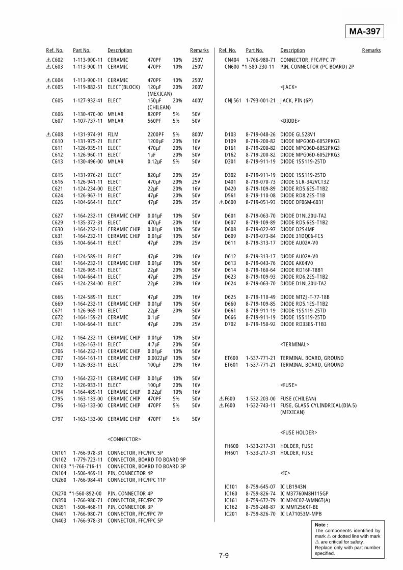
SLV-LX80S
7-9
Ref. No. Part No. Description Remarks Ref. No. Part No. Description Remarks
Note :The components identified bymark ! or dotted line with mark! are critical for safety.Replace only with part numberspecified.
MA-397
!C602 1-113-900-11 CERAMIC 470PF 10% 250V!C603 1-113-900-11 CERAMIC 470PF 10% 250V
!C604 1-113-900-11 CERAMIC 470PF 10% 250V!C605 1-119-882-51 ELECT(BLOCK) 120µF 20% 200V
(MEXICAN)C605 1-127-932-41 ELECT 150µF 20% 400V
(CHILEAN)C606 1-130-470-00 MYLAR 820PF 5% 50VC607 1-107-737-11 MYLAR 560PF 5% 50V
!C608 1-131-974-91 FILM 2200PF 5% 800VC610 1-131-975-21 ELECT 1200µF 20% 10VC611 1-126-935-11 ELECT 470µF 20% 16VC612 1-126-960-11 ELECT 1µF 20% 50VC613 1-130-496-00 MYLAR 0.12µF 5% 50V
C615 1-131-976-21 ELECT 820µF 20% 25VC616 1-126-941-11 ELECT 470µF 20% 25VC621 1-124-234-00 ELECT 22µF 20% 16VC624 1-126-967-11 ELECT 47µF 20% 50VC626 1-104-664-11 ELECT 47µF 20% 25V
C627 1-164-232-11 CERAMIC CHIP 0.01µF 10% 50VC629 1-135-372-31 ELECT 470µF 20% 10VC630 1-164-232-11 CERAMIC CHIP 0.01µF 10% 50VC631 1-164-232-11 CERAMIC CHIP 0.01µF 10% 50VC636 1-104-664-11 ELECT 47µF 20% 25V
C660 1-124-589-11 ELECT 47µF 20% 16VC661 1-164-232-11 CERAMIC CHIP 0.01µF 10% 50VC662 1-126-965-11 ELECT 22µF 20% 50VC664 1-104-664-11 ELECT 47µF 20% 25VC665 1-124-234-00 ELECT 22µF 20% 16V
C666 1-124-589-11 ELECT 47µF 20% 16VC669 1-164-232-11 CERAMIC CHIP 0.01µF 10% 50VC671 1-126-965-11 ELECT 22µF 20% 50VC672 1-164-159-21 CERAMIC 0.1µF 50VC701 1-104-664-11 ELECT 47µF 20% 25V
C702 1-164-232-11 CERAMIC CHIP 0.01µF 10% 50VC704 1-126-163-11 ELECT 4.7µF 20% 50VC706 1-164-232-11 CERAMIC CHIP 0.01µF 10% 50VC707 1-164-161-11 CERAMIC CHIP 0.0022µF 10% 50VC709 1-126-933-11 ELECT 100µF 20% 16V
C710 1-164-232-11 CERAMIC CHIP 0.01µF 10% 50VC712 1-126-933-11 ELECT 100µF 20% 16VC794 1-164-489-11 CERAMIC CHIP 0.22µF 10% 16VC795 1-163-133-00 CERAMIC CHIP 470PF 5% 50VC796 1-163-133-00 CERAMIC CHIP 470PF 5% 50V
C797 1-163-133-00 CERAMIC CHIP 470PF 5% 50V
<CONNECTOR>
CN101 1-766-978-31 CONNECTOR, FFC/FPC 5PCN102 1-779-723-11 CONNECTOR, BOARD TO BOARD 9PCN103 *1-766-716-11 CONNECTOR, BOARD TO BOARD 3PCN104 1-506-469-11 PIN, CONNECTOR 4PCN260 1-766-984-41 CONNECTOR, FFC/FPC 11P
CN270 *1-560-892-00 PIN, CONNECTOR 4PCN350 1-766-980-71 CONNECTOR, FFC/FPC 7PCN351 1-506-468-11 PIN, CONNECTOR 3PCN401 1-766-980-71 CONNECTOR, FFC/FPC 7PCN403 1-766-978-31 CONNECTOR, FFC/FPC 5P
CN404 1-766-980-71 CONNECTOR, FFC/FPC 7PCN600 *1-580-230-11 PIN, CONNECTOR (PC BOARD) 2P
<JACK>
CNJ561 1-793-001-21 JACK, PIN (6P)
<DIODE>
D103 8-719-048-26 DIODE GL528V1D109 8-719-200-82 DIODE MPG06D-6052PKG3D161 8-719-200-82 DIODE MPG06D-6052PKG3D162 8-719-200-82 DIODE MPG06D-6052PKG3D301 8-719-911-19 DIODE 1SS119-25TD
D302 8-719-911-19 DIODE 1SS119-25TDD401 8-719-070-73 DIODE SLR-342VCT32D420 8-719-109-89 DIODE RD5.6ES-T1B2D561 8-719-110-08 DIODE RD8.2ES-T1B
!D600 8-719-051-93 DIODE DF06M-6031
D601 8-719-063-70 DIODE D1NL20U-TA2D607 8-719-109-89 DIODE RD5.6ES-T1B2D608 8-719-022-97 DIODE D2S4MFD609 8-719-073-84 DIODE 31DQ06-FC5D611 8-719-313-17 DIODE AU02A-V0
D612 8-719-313-17 DIODE AU02A-V0D613 8-719-043-76 DIODE AK04V0D614 8-719-160-64 DIODE RD16F-T8B1D623 8-719-109-93 DIODE RD6.2ES-T1B2D624 8-719-063-70 DIODE D1NL20U-TA2
D625 8-719-110-49 DIODE MTZJ-T-77-18BD660 8-719-109-85 DIODE RD5.1ES-T1B2D661 8-719-911-19 DIODE 1SS119-25TDD666 8-719-911-19 DIODE 1SS119-25TDD702 8-719-150-92 DIODE RD33ES-T1B3
<TERMINAL>
ET600 1-537-771-21 TERMINAL BOARD, GROUNDET601 1-537-771-21 TERMINAL BOARD, GROUND
<FUSE>
!F600 1-532-203-00 FUSE (CHILEAN)!F600 1-532-743-11 FUSE, GLASS CYLINDRICAL(DIA.5)
(MEXICAN)
<FUSE HOLDER>
FH600 1-533-217-31 HOLDER, FUSEFH601 1-533-217-31 HOLDER, FUSE
<IC>
IC101 8-759-645-07 IC LB1943NIC160 8-759-826-74 IC M37760M8H115GPIC161 8-759-672-79 IC M24C02-WMN6T(A)IC162 8-759-248-87 IC MM1256XF-BEIC201 8-759-826-70 IC LA71053M-MPB

SLV-LX80S
7-10
Ref. No. Part No. Description Remarks Ref. No. Part No. Description Remarks
Note :The components identified bymark ! or dotted line with mark! are critical for safety.Replace only with part numberspecified.
MA-397
IC260 8-759-564-36 IC LA70011IC301 8-759-696-39 IC AN3668FBPIC350 8-759-499-30 IC BA7755AF-E2IC404 8-759-643-83 IC UPD16315GB-3BSIC570 8-759-566-07 IC LA7277M-TLM
! IC600 8-749-018-38 IC MA8910! IC601 8-759-321-95 IC HA17431PA-TZ
IC660 8-759-438-18 IC PQ12RD08
<CHIP CONDUCTOR>
JR001 1-216-295-00 SHORT 0JR002 1-216-295-00 SHORT 0JR003 1-216-295-00 SHORT 0JR004 1-216-295-00 SHORT 0JR005 1-216-295-00 SHORT 0
JR006 1-216-295-00 SHORT 0JR007 1-216-295-00 SHORT 0JR008 1-216-295-00 SHORT 0JR009 1-216-295-00 SHORT 0JR010 1-216-295-00 SHORT 0
JR011 1-216-295-00 SHORT 0JR012 1-216-295-00 SHORT 0JR013 1-216-295-00 SHORT 0JR014 1-216-295-00 SHORT 0JR015 1-216-295-00 SHORT 0
JR016 1-216-295-00 SHORT 0JR017 1-216-295-00 SHORT 0JR018 1-216-295-00 SHORT 0JR019 1-216-295-00 SHORT 0JR020 1-216-295-00 SHORT 0
JR021 1-216-295-00 SHORT 0JR022 1-216-295-00 SHORT 0JR023 1-216-295-00 SHORT 0JR024 1-216-295-00 SHORT 0JR025 1-216-295-00 SHORT 0
JR026 1-216-295-00 SHORT 0JR027 1-216-295-00 SHORT 0JR031 1-216-295-00 SHORT 0JR101 1-216-296-00 SHORT 0JR102 1-216-296-00 SHORT 0
JR103 1-216-296-00 SHORT 0JR104 1-216-296-00 SHORT 0JR105 1-216-296-00 SHORT 0JR106 1-216-296-00 SHORT 0JR107 1-216-296-00 SHORT 0
JR108 1-216-296-00 SHORT 0JR109 1-216-296-00 SHORT 0JR110 1-216-296-00 SHORT 0JR111 1-216-296-00 SHORT 0JR112 1-216-296-00 SHORT 0
JR113 1-216-296-00 SHORT 0JR114 1-216-296-00 SHORT 0JR115 1-216-296-00 SHORT 0JR116 1-216-296-00 SHORT 0JR117 1-216-296-00 SHORT 0
JR118 1-216-296-00 SHORT 0JR119 1-216-296-00 SHORT 0JR120 1-216-296-00 SHORT 0JR121 1-216-296-00 SHORT 0JR122 1-216-296-00 SHORT 0
JR123 1-216-296-00 SHORT 0JR124 1-216-296-00 SHORT 0JR125 1-216-296-00 SHORT 0JR126 1-216-296-00 SHORT 0JR127 1-216-296-00 SHORT 0
JR128 1-216-296-00 SHORT 0JR129 1-216-296-00 SHORT 0JR130 1-216-296-00 SHORT 0JR131 1-216-296-00 SHORT 0JR132 1-216-296-00 SHORT 0
JR133 1-216-296-00 SHORT 0JR134 1-216-296-00 SHORT 0JR135 1-216-296-00 SHORT 0JR136 1-216-296-00 SHORT 0JR137 1-216-296-00 SHORT 0
JR138 1-216-296-00 SHORT 0JR139 1-216-296-00 SHORT 0JR140 1-216-296-00 SHORT 0JR141 1-216-296-00 SHORT 0JR142 1-216-296-00 SHORT 0
JR143 1-216-296-00 SHORT 0JR144 1-216-296-00 SHORT 0JR145 1-216-296-00 SHORT 0JR146 1-216-296-00 SHORT 0JR147 1-216-296-00 SHORT 0
JR148 1-216-296-00 SHORT 0JR149 1-216-296-00 SHORT 0
<JUMPER SELECTOR>
JS304 1-216-295-00 SHORT 0JS452 1-216-295-00 SHORT 0JS570 1-216-295-00 SHORT 0JS603 1-216-296-00 SHORT 0JS604 1-216-296-00 SHORT 0
JS614 1-216-295-00 SHORT 0JS616 1-216-296-00 SHORT 0
<COIL>
L101 1-414-179-51 INDUCTOR 2.2µHL161 1-414-185-51 INDUCTOR 22µHL162 1-414-185-51 INDUCTOR 22µHL163 1-414-185-51 INDUCTOR 22µHL201 1-414-946-21 INDUCTOR 39µH
L202 1-414-857-51 INDUCTOR 100µHL203 1-414-856-51 INDUCTOR 10µHL204 1-414-857-51 INDUCTOR 100µHL205 1-414-857-51 INDUCTOR 100µHL206 1-414-857-51 INDUCTOR 100µH
L207 1-414-193-51 INDUCTOR 220µHL270 1-414-857-51 INDUCTOR 100µH

SLV-LX80S
7-11
Ref. No. Part No. Description Remarks Ref. No. Part No. Description Remarks
MA-397
Note :The components identified bymark ! or dotted line with mark! are critical for safety.Replace only with part numberspecified.
L303 1-414-857-51 INDUCTOR 100µHL380 1-414-857-51 INDUCTOR 100µHL420 1-414-185-51 INDUCTOR 22µH
L500 1-414-930-21 INDUCTOR 2.2µHL501 1-414-857-51 INDUCTOR 100µHL561 1-414-857-51 INDUCTOR 100µHL570 1-414-857-51 INDUCTOR 100µHL601 1-403-588-11 INDUCTOR 22µH
L602 1-403-588-11 INDUCTOR 22µHL603 1-414-142-11 INDUCTOR 1µHL604 1-414-142-11 INDUCTOR 1µHL606 1-414-142-11 INDUCTOR 1µHL660 1-410-519-11 INDUCTOR 68µH
L703 1-414-179-51 INDUCTOR 2.2µHL704 1-414-179-51 INDUCTOR 2.2µH
<FILTER>
!LF600 1-416-929-11 FILTER, LINE
<FLOURESCENT INDICATOR TUBE>
ND420 1-517-925-11 TUBE, FLUORESCENT INDICATOR
<PHOTO COUPLER>
PH101 8-749-015-86 PHOTO INTERRUPTER GP3S120SPH102 8-749-015-86 PHOTO INTERRUPTER GP3S120S
!PH600 8-749-014-24 COUPLER, PHOTO PC123FY2
<IC LINK>
!PS101 1-532-727-11 LINK, IC 0.25A/150V!PS662 1-533-710-11 FUSE (SMD)
<TRANSISTOR>
Q101 8-729-047-02 TRANSISTOR RPT-37PBT32LQ102 8-729-043-84 TRANSISTOR PT380F3Q103 8-729-281-53 TRANSISTOR 2SC1815GR-TPE2Q201 8-729-230-49 TRANSISTOR 2SC2712Y-TE85LQ202 8-729-230-49 TRANSISTOR 2SC2712Y-TE85L
Q203 8-729-216-21 TRANSISTOR 2SA1162Y-TE85LQ204 8-729-422-27 TRANSISTOR 2SD601A-QRS-TXQ301 8-729-216-21 TRANSISTOR 2SA1162Y-TE85LQ302 8-729-230-49 TRANSISTOR 2SC2712Y-TE85LQ303 8-729-230-49 TRANSISTOR 2SC2712Y-TE85L
Q350 8-729-281-53 TRANSISTOR 2SC1815GR-TPE2Q380 8-729-821-15 TRANSISTOR 2SD1620-TDQ500 8-729-216-22 TRANSISTOR 2SB709A-QRS-TXQ502 8-729-216-21 TRANSISTOR 2SA1162Y-TE85LQ561 8-729-216-22 TRANSISTOR 2SB709A-QRS-TX
Q600 8-729-047-92 TRANSISTOR 2SB1398-Q(TA).S0Q601 8-729-422-27 TRANSISTOR 2SD601A-QRS-TXQ662 8-729-019-01 TRANSISTOR 2SD2394-EFQ673 8-729-119-78 TRANSISTOR 2SC3311A-RTAQ674 8-729-106-68 TRANSISTOR 2SD1664-T100-R
<RESISTOR>
R101 1-249-413-11 CARBON 470 5% 1/4WR102 1-216-077-91 RES-CHIP 15K 5% 1/10WR103 1-216-077-91 RES-CHIP 15K 5% 1/10WR104 1-216-081-00 RES-CHIP 22K 5% 1/10WR105 1-249-433-11 CARBON 22K 5% 1/4W
R106 1-249-400-11 CARBON 39 5% 1/4WR107 1-249-400-11 CARBON 39 5% 1/4WR109 1-249-437-11 CARBON 47K 5% 1/4WR110 1-216-089-00 RES-CHIP 47K 5% 1/10WR111 1-216-057-00 RES-CHIP 2.2K 5% 1/10W
R112 1-216-065-00 RES-CHIP 4.7K 5% 1/10WR113 1-216-073-00 RES-CHIP 10K 5% 1/10WR114 1-216-073-00 RES-CHIP 10K 5% 1/10WR115 1-216-089-00 RES-CHIP 47K 5% 1/10WR116 1-216-089-00 RES-CHIP 47K 5% 1/10W
R117 1-216-041-00 RES-CHIP 470 5% 1/10WR118 1-216-089-00 RES-CHIP 47K 5% 1/10WR119 1-216-077-91 RES-CHIP 15K 5% 1/10WR120 1-249-417-11 CARBON 1K 5% 1/4WR121 1-249-413-11 CARBON 470 5% 1/4W
R142 1-216-051-00 RES-CHIP 1.2K 5% 1/10WR143 1-216-065-00 RES-CHIP 4.7K 5% 1/10WR159 1-216-097-11 RES-CHIP 100K 5% 1/10WR160 1-216-049-00 RES-CHIP 1K 5% 1/10WR161 1-216-073-00 RES-CHIP 10K 5% 1/10W
R162 1-247-843-11 CARBON 3.3K 5% 1/4WR164 1-216-089-00 RES-CHIP 47K 5% 1/10WR165 1-216-089-00 RES-CHIP 47K 5% 1/10WR166 1-216-073-00 RES-CHIP 10K 5% 1/10WR167 1-249-431-11 CARBON 15K 5% 1/4W
R168 1-216-073-00 RES-CHIP 10K 5% 1/10WR169 1-216-073-00 RES-CHIP 10K 5% 1/10WR170 1-247-843-11 CARBON 3.3K 5% 1/4WR171 1-216-089-00 RES-CHIP 47K 5% 1/10WR172 1-216-073-00 RES-CHIP 10K 5% 1/10W
R174 1-216-039-00 RES-CHIP 390 5% 1/10WR175 1-249-413-11 CARBON 470 5% 1/4WR176 1-249-413-11 CARBON 470 5% 1/4WR177 1-249-413-11 CARBON 470 5% 1/4WR178 1-216-105-91 RES-CHIP 220K 5% 1/10W
R179 1-216-113-00 RES-CHIP 470K 5% 1/10WR180 1-216-061-00 RES-CHIP 3.3K 5% 1/10WR183 1-216-295-00 SHORT 0R185 1-216-295-00 SHORT 0R187 1-216-295-00 SHORT 0
R188 1-216-069-00 RES-CHIP 6.8K 5% 1/10WR189 1-216-061-00 RES-CHIP 3.3K 5% 1/10WR191 1-249-417-11 CARBON 1K 5% 1/4WR192 1-249-417-11 CARBON 1K 5% 1/4WR193 1-216-295-00 SHORT 0
R194 1-216-073-00 RES-CHIP 10K 5% 1/10WR201 1-216-037-00 RES-CHIP 330 5% 1/10WR202 1-216-047-91 RES-CHIP 820 5% 1/10WR203 1-216-037-00 RES-CHIP 330 5% 1/10WR204 1-216-071-00 RES-CHIP 8.2K 5% 1/10W
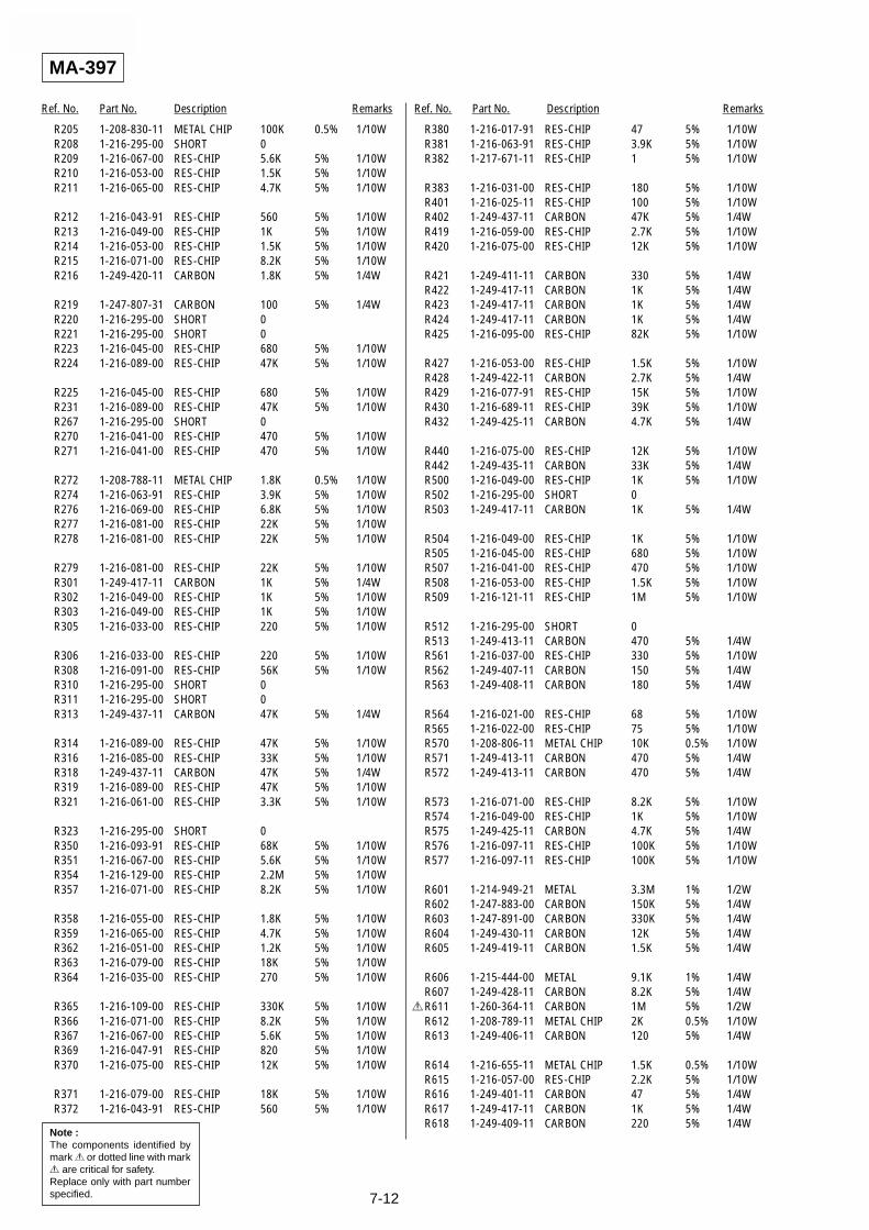
SLV-LX80S
7-12
Ref. No. Part No. Description Remarks Ref. No. Part No. Description Remarks
MA-397
Note :The components identified bymark ! or dotted line with mark! are critical for safety.Replace only with part numberspecified.
R205 1-208-830-11 METAL CHIP 100K 0.5% 1/10WR208 1-216-295-00 SHORT 0R209 1-216-067-00 RES-CHIP 5.6K 5% 1/10WR210 1-216-053-00 RES-CHIP 1.5K 5% 1/10WR211 1-216-065-00 RES-CHIP 4.7K 5% 1/10W
R212 1-216-043-91 RES-CHIP 560 5% 1/10WR213 1-216-049-00 RES-CHIP 1K 5% 1/10WR214 1-216-053-00 RES-CHIP 1.5K 5% 1/10WR215 1-216-071-00 RES-CHIP 8.2K 5% 1/10WR216 1-249-420-11 CARBON 1.8K 5% 1/4W
R219 1-247-807-31 CARBON 100 5% 1/4WR220 1-216-295-00 SHORT 0R221 1-216-295-00 SHORT 0R223 1-216-045-00 RES-CHIP 680 5% 1/10WR224 1-216-089-00 RES-CHIP 47K 5% 1/10W
R225 1-216-045-00 RES-CHIP 680 5% 1/10WR231 1-216-089-00 RES-CHIP 47K 5% 1/10WR267 1-216-295-00 SHORT 0R270 1-216-041-00 RES-CHIP 470 5% 1/10WR271 1-216-041-00 RES-CHIP 470 5% 1/10W
R272 1-208-788-11 METAL CHIP 1.8K 0.5% 1/10WR274 1-216-063-91 RES-CHIP 3.9K 5% 1/10WR276 1-216-069-00 RES-CHIP 6.8K 5% 1/10WR277 1-216-081-00 RES-CHIP 22K 5% 1/10WR278 1-216-081-00 RES-CHIP 22K 5% 1/10W
R279 1-216-081-00 RES-CHIP 22K 5% 1/10WR301 1-249-417-11 CARBON 1K 5% 1/4WR302 1-216-049-00 RES-CHIP 1K 5% 1/10WR303 1-216-049-00 RES-CHIP 1K 5% 1/10WR305 1-216-033-00 RES-CHIP 220 5% 1/10W
R306 1-216-033-00 RES-CHIP 220 5% 1/10WR308 1-216-091-00 RES-CHIP 56K 5% 1/10WR310 1-216-295-00 SHORT 0R311 1-216-295-00 SHORT 0R313 1-249-437-11 CARBON 47K 5% 1/4W
R314 1-216-089-00 RES-CHIP 47K 5% 1/10WR316 1-216-085-00 RES-CHIP 33K 5% 1/10WR318 1-249-437-11 CARBON 47K 5% 1/4WR319 1-216-089-00 RES-CHIP 47K 5% 1/10WR321 1-216-061-00 RES-CHIP 3.3K 5% 1/10W
R323 1-216-295-00 SHORT 0R350 1-216-093-91 RES-CHIP 68K 5% 1/10WR351 1-216-067-00 RES-CHIP 5.6K 5% 1/10WR354 1-216-129-00 RES-CHIP 2.2M 5% 1/10WR357 1-216-071-00 RES-CHIP 8.2K 5% 1/10W
R358 1-216-055-00 RES-CHIP 1.8K 5% 1/10WR359 1-216-065-00 RES-CHIP 4.7K 5% 1/10WR362 1-216-051-00 RES-CHIP 1.2K 5% 1/10WR363 1-216-079-00 RES-CHIP 18K 5% 1/10WR364 1-216-035-00 RES-CHIP 270 5% 1/10W
R365 1-216-109-00 RES-CHIP 330K 5% 1/10WR366 1-216-071-00 RES-CHIP 8.2K 5% 1/10WR367 1-216-067-00 RES-CHIP 5.6K 5% 1/10WR369 1-216-047-91 RES-CHIP 820 5% 1/10WR370 1-216-075-00 RES-CHIP 12K 5% 1/10W
R371 1-216-079-00 RES-CHIP 18K 5% 1/10WR372 1-216-043-91 RES-CHIP 560 5% 1/10W
R380 1-216-017-91 RES-CHIP 47 5% 1/10WR381 1-216-063-91 RES-CHIP 3.9K 5% 1/10WR382 1-217-671-11 RES-CHIP 1 5% 1/10W
R383 1-216-031-00 RES-CHIP 180 5% 1/10WR401 1-216-025-11 RES-CHIP 100 5% 1/10WR402 1-249-437-11 CARBON 47K 5% 1/4WR419 1-216-059-00 RES-CHIP 2.7K 5% 1/10WR420 1-216-075-00 RES-CHIP 12K 5% 1/10W
R421 1-249-411-11 CARBON 330 5% 1/4WR422 1-249-417-11 CARBON 1K 5% 1/4WR423 1-249-417-11 CARBON 1K 5% 1/4WR424 1-249-417-11 CARBON 1K 5% 1/4WR425 1-216-095-00 RES-CHIP 82K 5% 1/10W
R427 1-216-053-00 RES-CHIP 1.5K 5% 1/10WR428 1-249-422-11 CARBON 2.7K 5% 1/4WR429 1-216-077-91 RES-CHIP 15K 5% 1/10WR430 1-216-689-11 RES-CHIP 39K 5% 1/10WR432 1-249-425-11 CARBON 4.7K 5% 1/4W
R440 1-216-075-00 RES-CHIP 12K 5% 1/10WR442 1-249-435-11 CARBON 33K 5% 1/4WR500 1-216-049-00 RES-CHIP 1K 5% 1/10WR502 1-216-295-00 SHORT 0R503 1-249-417-11 CARBON 1K 5% 1/4W
R504 1-216-049-00 RES-CHIP 1K 5% 1/10WR505 1-216-045-00 RES-CHIP 680 5% 1/10WR507 1-216-041-00 RES-CHIP 470 5% 1/10WR508 1-216-053-00 RES-CHIP 1.5K 5% 1/10WR509 1-216-121-11 RES-CHIP 1M 5% 1/10W
R512 1-216-295-00 SHORT 0R513 1-249-413-11 CARBON 470 5% 1/4WR561 1-216-037-00 RES-CHIP 330 5% 1/10WR562 1-249-407-11 CARBON 150 5% 1/4WR563 1-249-408-11 CARBON 180 5% 1/4W
R564 1-216-021-00 RES-CHIP 68 5% 1/10WR565 1-216-022-00 RES-CHIP 75 5% 1/10WR570 1-208-806-11 METAL CHIP 10K 0.5% 1/10WR571 1-249-413-11 CARBON 470 5% 1/4WR572 1-249-413-11 CARBON 470 5% 1/4W
R573 1-216-071-00 RES-CHIP 8.2K 5% 1/10WR574 1-216-049-00 RES-CHIP 1K 5% 1/10WR575 1-249-425-11 CARBON 4.7K 5% 1/4WR576 1-216-097-11 RES-CHIP 100K 5% 1/10WR577 1-216-097-11 RES-CHIP 100K 5% 1/10W
R601 1-214-949-21 METAL 3.3M 1% 1/2WR602 1-247-883-00 CARBON 150K 5% 1/4WR603 1-247-891-00 CARBON 330K 5% 1/4WR604 1-249-430-11 CARBON 12K 5% 1/4WR605 1-249-419-11 CARBON 1.5K 5% 1/4W
R606 1-215-444-00 METAL 9.1K 1% 1/4WR607 1-249-428-11 CARBON 8.2K 5% 1/4W
!R611 1-260-364-11 CARBON 1M 5% 1/2WR612 1-208-789-11 METAL CHIP 2K 0.5% 1/10WR613 1-249-406-11 CARBON 120 5% 1/4W
R614 1-216-655-11 METAL CHIP 1.5K 0.5% 1/10WR615 1-216-057-00 RES-CHIP 2.2K 5% 1/10WR616 1-249-401-11 CARBON 47 5% 1/4WR617 1-249-417-11 CARBON 1K 5% 1/4WR618 1-249-409-11 CARBON 220 5% 1/4W

SLV-LX80S
7-13
Ref. No. Part No. Description Remarks Ref. No. Part No. Description Remarks
MA-397
Note :The components identified bymark ! or dotted line with mark! are critical for safety.Replace only with part numberspecified.
R621 1-249-429-11 CARBON 10K 5% 1/4WR622 1-216-430-11 METAL OXIDE 390 5% 1WR623 1-247-843-11 CARBON 3.3K 5% 1/4W
!R640 1-219-153-11 FUSIBLE 10 5% 1/4W!R641 1-219-153-11 FUSIBLE 10 5% 1/4W
R643 1-216-349-00 METAL OXIDE 1 5% 1WR647 1-215-465-00 METAL 68K 1% 1/4WR648 1-216-057-00 RES-CHIP 2.2K 5% 1/10WR649 1-216-017-91 RES-CHIP 47 5% 1/10WR651 1-215-459-00 METAL 39K 1% 1/4W
R669 1-216-061-00 RES-CHIP 3.3K 5% 1/10WR676 1-249-417-11 CARBON 1K 5% 1/4WR678 1-249-409-11 CARBON 220 5% 1/4WR679 1-249-409-11 CARBON 220 5% 1/4WR680 1-249-417-11 CARBON 1K 5% 1/4W
R701 1-249-417-11 CARBON 1K 5% 1/4WR702 1-216-061-00 RES-CHIP 3.3K 5% 1/10WR703 1-249-412-11 CARBON 390 5% 1/4WR704 1-216-043-91 RES-CHIP 560 5% 1/10WR709 1-216-049-00 RES-CHIP 1K 5% 1/10W
R710 1-216-049-00 RES-CHIP 1K 5% 1/10WR711 1-216-049-00 RES-CHIP 1K 5% 1/10WR712 1-216-295-00 SHORT 0
!R723 1-240-307-81 FUSIBLE 560 5% 1/4WR724 1-216-113-00 RES-CHIP 470K 5% 1/10W
<SWITCH>
S101 1-762-108-11 SWITCH, PUSH (1 KEY) REC PROOFS102 1-771-155-11 SWITCH, ROTARY MODES421 1-771-574-21 SWITCH, TACTILE REALITY
GENERATORS422 1-771-574-21 SWITCH, TACTILE EASY SET-UPS423 1-771-574-21 SWITCH, TACTILE CHANNEL/
TRACKING-
S424 1-771-574-21 SWITCH, TACTILE CHANNEL/TRACKING+
S426 1-771-574-21 SWITCH, TACTILE SYNCS701 1-571-588-11 SWITCH, SLIDE RF UNIT
(CH3 y CH4)
<TRANSFORMER>
T380 1-431-097-11 TRANSFORMER, BIAS OSCILLATIONT600 1-435-790-11 TRANSFORMER, CONVERTER
<TUNER>
TU701 1-693-532-11 TUNER IF (BTF-3MA413)
<VARISTOR>
!VDR600 1-801-267-31 VARISTOR TNR10V431K660(CHILEAN)
!VDR600 1-804-048-31 VARISTOR (240NS10D)(MEXICAN)
<CRYSTAL>
X160 1-767-857-11 VIBRATOR, CRYSTAL 14.31818 MHzX161 1-579-463-11 VIBRATOR, CRYSTAL 32.469 KHzX201 1-577-380-11 VIBRATOR, CRYSTAL 3.79545 MHz
MISCELLANEOUS**************
1-782-000-33 CORD, POWER (CHILEAN)1-777-852-33 CORD, POWER (MEXICAN)
6 1-757-552-12 FLAT CABLE FDM-0108 1-757-553-11 FLAT CABLE FD1-00210 1-757-553-11 FLAT CABLE FFJ-006
55 1-757-550-11 FLAT CABLE FMD-02156 1-757-551-11 FLAT CABLE FAC-009704 1-500-471-11 FE HEAD721 A-6759-620-A HEAD BLOCK ASSY,ACEM902 1-698-971-11 MOTOR, DC
M903 X-3947-577-1 MOTOR ASSY, CAM770 1-772-366-11 DRUM ASSY, DZH-0B7A-R
ACCESSORIES************
1-569-008-21 ADAPTOR, CONVERSION 2P(CHILEAN)
3-065-285-11 MANUAL, INSTRUCTION1-751-271-12 CORD, CONNECTION1-751-271-12 CORD (WITH CONNECTOR)1-696-592-11 CORD, CONNECTION (NTSC)
1-476-437-11 COMMANDER, STANDARD(RMT-V294A)3-709-432-11 COVER, REMOTE CONTROL BATTERY
HARDWARE LIST**************
3-710-901-61 SCREW, TAPPING7-682-647-09 SCREW +PS 3X6
#1 7-685-648-79 SCREW + BVTP 3 x 12 TYPE 2 IT-3#2 7-685-646-79 SCREW + BCTP 3 x 8 TYPE IT-3#3 7-682-647-09 SCREW + P3 x 6#4 7-685-133-19 SCREW + P2.6 x 6 TYPE2 NON-SLIT
7-13E

SLV-LX80S
7-14
Ref. No. Part No. Description Remarks Ref. No. Part No. Description Remarks
Sony CorporationNETWORK ENTERTAINMENT GROUP
20001A0800-1 2001. 1
Published by Quality Assurance Dept.9-921-785-11
SLV-LX80S
– 86 –