
slurry residue. Some moisture-sensitive materials may … · generally includes an air-entraining...
73
64 Figure 16. Protective shield around waterblasting operation. the concrete changes (for example, a harder aggregate has been used in one section of the highway). If the concrete does change, the waterblasting machine must be recalibrated using two new trial areas in the section of the highway with the different concrete. All unsound concrete within a marked spalled area should be removed to a minimum depth of 50 mm with neat vertical faces. Then the repair area must be tested again for soundness. Any additional unsound concrete must be removed by continued waterblasting. A full-depth repair must be used if the deterioration is found to be deeper than the top third of the pavement slab, or if reinforcing bars or mesh are reached. The debris and slurry that result from the waterblasting operation must be removed using a low-pressure water stream before the slurry dries and hardens on the surface of the hole. If this is not done, the repair area may have to be refaced. Once dried, sandblasting may or may not be able to remove the dried
Transcript of slurry residue. Some moisture-sensitive materials may … · generally includes an air-entraining...

64
Figure 16. Protective shield around waterblasting operation.
the concrete changes (for example, a harder aggregate has beenused in one section of the highway). If the concrete doeschange, the waterblasting machine must be recalibrated usingtwo new trial areas in the section of the highway with thedifferent concrete.
All unsound concrete within a marked spalled area should beremoved to a minimum depth of 50 mm with neat vertical faces. Then the repair area must be tested again for soundness. Anyadditional unsound concrete must be removed by continuedwaterblasting. A full-depth repair must be used if thedeterioration is found to be deeper than the top third of thepavement slab, or if reinforcing bars or mesh are reached.
The debris and slurry that result from the waterblastingoperation must be removed using a low-pressure water streambefore the slurry dries and hardens on the surface of the hole. Ifthis is not done, the repair area may have to be refaced. Oncedried, sandblasting may or may not be able to remove the dried

65
slurry residue. Some moisture-sensitive materials may requirethe repair area be completely dry before placing the material.
4.5.5 Clean and Patch
Under adverse conditions, handpicks and shovels should beused to remove loose material. A light jackhammer maysometimes be used for larger areas.
4.6 Cleaning the Repair Area
After all unsound concrete has been removed, the surface of therepair area must be cleaned. Sandblasting, airblasting, andsweeping normally provide a clean, rough surface for thedevelopment of a good bond between the patch and thepavement. High-pressure water may also be used to removedirt, dust, and other contaminants, but sandblasting usuallyproduces better results.
4.6.1 Sandblasting
Sandblasting, shown in figure 17, is highly recommended forcleaning the surface. It removes dirt, oil, thin layers of unsoundconcrete, and laitance. Sandblasting equipment consists of acompressed air unit, a sand dispenser, hoses, and a wand with aventuri-type nozzle. The compressed air must be free of oil andwater, since a contaminated surface will prevent bonding. Theair quality can be checked by placing a cloth over the aircompressor nozzle and visually inspecting for oil. Sandblastingis generally not used under adverse conditions.

66
Figure 17. Sandblasting.
4.6.2 Airblasting
After sandblasting, high-pressure airblasting should be used toremove any remaining dust, debris, and loosened concretefragments. Debris must be blown out and away from the patchso that wind or passing traffic cannot carry it back into thepatch. The cleanliness of the repair area must be checked usinga black glove or cloth. If the glove or cloth picks up material(dust, asphalt, slurry) when rubbed across the prepared surface,the surface should be cleaned again or poor bonding will result. If there is a delay between cleaning and patch placement, thesurface may have to be cleaned again. Airblasting is generallynot used with the clean-and-patch procedure under adverseconditions.
Either trailer-mounted air compressors or portable backpackblowers may be used. Backpack blowers need only one laborerand are very mobile. However, trailer-mounted air compressors

67
are recommended because they provide a higher pressure(greater than 670 kPa). The compressed air unit should haveoil and moisture filters; otherwise, it may blow oil or moistureinto the repair area and prevent the patch from bonding. Whenpatching with a spray-injection machine (e.g., AMZ, Rosco),the hole may be cleaned with its blower.
4.6.3 Sweeping
Sweeping is most commonly used to clean the repair area whenpatching under adverse conditions. Under better conditions,sandblasting and airblasting should be used.
4.7 Final Joint Preparation
If a nonflexible repair material is used, a compressible jointbond breaker must be installed as the last step of jointpreparation. The type of joint (i.e., transverse, centerline, orlane-shoulder) will determine the type of bond breaker to use. Some flexible materials may not need a bond breaker.
Polystyrene or polyethylene joint bond breakers are placed flushwith the pavement surface, between the new (nonflexible)concrete and the adjacent slab to reduce the risk ofcompression-related failure. They also protect the patch fromdamage caused by deflection under traffic.
The bond breaker should have a scored top strip as shown infigure 2. It should extend 25 mm below and 75 mm beyond therepair boundaries, as shown in figure 18a. The extension willprevent the repair material from flowing into the joint duringplacement. Figure 18b shows a bond breaker installedimproperly, as there is not enough length to extend beyond therepair boundary along the top (longitudinal) edge of the repairarea. The bond breaker should be slightly wider than the joint

68
Figure 18a. Correct dimensions of joint bondbreaker placement at one joint.
Figure 18b. Incorrectly installed bondbreaker at two joints.
69
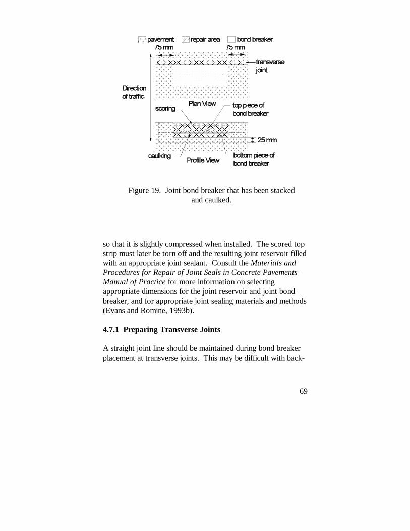
Figure 19. Joint bond breaker that has been stackedand caulked.
so that it is slightly compressed when installed. The scored topstrip must later be torn off and the resulting joint reservoir filledwith an appropriate joint sealant. Consult the Materials andProcedures for Repair of Joint Seals in Concrete Pavements–Manual of Practice for more information on selectingappropriate dimensions for the joint reservoir and joint bondbreaker, and for appropriate joint sealing materials and methods(Evans and Romine, 1993b).
4.7.1 Preparing Transverse Joints
A straight joint line should be maintained during bond breakerplacement at transverse joints. This may be difficult with back-

70
to-back patches. Bond breakers of different heights may beinstalled in patches of different depths. Alternatively, the bondbreaker may be stacked to the needed depth, which may bedifficult. Latex caulking may be used to seal any gaps betweenlayers of bond breaker or between the bond breaker and thejoint opening, as illustrated in figure 19. This will prevent therepair material from flowing into the joint or a crack openingbelow the bottom of the patch.
4.7.2 Preparing Centerline Joints
Partial-depth patches placed at the centerline joint often spallbecause of curling stresses. To prevent this, a polyethylenestrip (or other thin bond-breaker material) must be placed alongthe centerline joint to prevent the patch from contacting theadjacent lane, as described in section 4.7.1.
4.7.3 Preparing Lane-Shoulder Joints
The joint must be formed using a piece of fiberboard if therepair is at the lane-shoulder joint. Fiberboard is stiffer than apolyethylene or polystyrene joint bond breaker, and it providesthe support needed at the lane-shoulder joint when placing therepair material. Like more flexible bond breakers, fiberboardwill prevent the repair material from flowing into the shoulderduring material placement. If the repair material flows into thelane-shoulder joint, it will restrict longitudinal movement of theslab and damage the repair. Fiberboard must be placed to thesame dimensions as the more flexible bond breaker, as shown infigure 18.
4.7.4 Using Flexible Repair Materials
Some proprietary flexible repair materials, such as Percol FLand Penatron R/M-3003, and some bituminous materials, suchas UPM High-Performance Cold Mix and spray-injection mix

71
(e.g., AMZ, Rosco), may have enough compressibility to allowjoints to move without needing a joint bond breaker. Themanufacturer should be consulted for the appropriate jointtreatment when using a flexible spall repair material.
4.8 Pre-Placement Inspection of the Repair Area
After cleaning, the repair area should be inspected to determineif there is any more unsound concrete. If there is, it should beremoved, and the repair area should be cleaned again. Sandblasting should never be used to remove unsound material.
If the repair area is sound, it should then be inspected for clean,dry, freshly exposed concrete. Any dust remaining on thepavement surface around the repair area should be removed bysweeping, especially on windy days or when traffic passesalongside the repair. If there is a delay between cleaning andplacing the material, the repair area must be inspected again atthe time of placement, and must be cleaned again by airblowingif dirt has blown into it.
4.9 Mixing the Bonding Agent
Some partial-depth patching materials require epoxy orproprietary bonding agents. Epoxy bonding agents should bemixed carefully according to the manufacturer's instructions. An electric drill with a Jiffy mixer may be used to mix the twoepoxy components for the required time.
Some spall repair materials, such as SikaPronto 11, specify aproprietary bonding agent. The manufacturer's mixinginstructions should be followed exactly to ensure good patchperformance.

72
4.10 Mixing the Repair Material
The volume of material required for a partial-depth repair isusually small (0.014 m3 to 0.057 m3). Ready-mix trucks andother large equipment cannot efficiently produce smallquantities. Small drum or paddle-type mixers with capacities of0.17 m3 to 0.23 m3 and Jiffy mixers are often used. Based ontrial batches, repair materials may be weighed and bagged inadvance to make the batching process easier. Prebaggedcement may also be used; aggregate may be weighed using aprecalibrated volume method (i.e., a bucket can be marked byvolume for the appropriate weight). Continuous-feed mixersare also widely used.
Mixing times and water content must be carefully observed forprepackaged rapid-setting materials. Mixing for a longer timethan needed for good blending reduces the already short timeavailable for placing and finishing rapid-setting materials. Additional water may significantly reduce the strength of thepatch.
4.10.1 Cementitious Concretes
Rapid-setting cementitious materials used in partial-depth spallrepair, such as Type III PCC, gypsum-based concrete (e.g.,Duracal), magnesium phosphate concrete (e.g., Set-45), andhigh alumina concrete (e.g., Five Star HP), generally are mixedwith small drum or mortar mixers, as shown in figure 20.
The proportions of water, aggregate, and cement depend on thetype of material selected. A rapid-setting Type III PCC mixgenerally includes an air-entraining agent, an accelerating agent,and a superplasticizer. In addition to the cement itself, rapid-setting cementitious materials need clean water and amanufacturer-specified gradation of aggregate. Someproprietary materials (e.g., Duracal) also need sand. Most

73
Figure 20. Adding carefully measured components to adrum mixer.
cementitious materials require that the water be added to therunning mixer, followed by the aggregate, and then the cement. Warm water may be needed at air temperatures below 13oC,while ice water may be needed at higher temperatures. Themanufacturer's recommendations for proportions, mixingsequence, and mixing times for each component should befollowed exactly.
4.10.2 Polymer Concretes
Polymer concretes, such as epoxies (e.g., MC-64), methylmethacrylates (e.g., SikaPronto 11), and polyurethanes (e.g.,Percol FL, Penatron R/M-3003), are generally mixed with a

74
Jiffy mixer or a mortar mixer, as specified by the materialmanufacturer.
The materials usually consist of two or more premeasuredliquid components, or a liquid component and cementitiouscomponents. The different components are generally mixedseparately and then in combination. Mortar mixers are used formixing large batches of liquid components and for mixingcementitious components with aggregate. Jiffy mixers are usedfor mixing small batches of liquid components, as shown infigure 21. Liquid mixtures are either mixed with or pouredover a specified gradation of oven-dried aggregate. Themanufacturer's recommendations for mixing sequence,component amounts, and mixing times should be followedexactly.
4.10.3 Bituminous Materials
Bituminous cold mixes (e.g., UPM High-Performance ColdMix) are generally mixed at a local plant using themanufacturer's mix design. They may also come premixed indrums, buckets, or bags. When patching spalls with a spray-injection machine (e.g., AMZ, Rosco), the machine mixesasphalt emulsion heated to approximately 57oC and aggregate. An experienced operator should carefully control the volume ofeach component. The asphalt and aggregate are sprayed outunder pressure. Care should be taken not to overfill or to spillmaterial outside of the repair area.

75
Figure 21. Using a jiffy mixer.
4.11 Applying the Bonding Agent
A bonding agent should be applied after cleaning the repair areaand just before placing PCC repair materials. Themanufacturer's directions must be closely followed when usingepoxies or other manufactured grouts. The bottom and sides ofthe repair area must be thoroughly coated by brushing the groutor epoxy onto the concrete as shown in figure 22. Sprayingmay be appropriate for large repair areas. Excess bondingagent should not be allowed to collect in pockets. Theplacement of the bonding agent should be timed so that it istacky when the repair material is placed.

76
Figure 22. Applying bonding agent.
4.12 Placing the Repair Material
For materials that will be consolidated or compacted, theplacement procedure begins by slightly overfilling the repairhole to allow for the reduction in volume. Materials thatcontain aggregate must be placed with a shovel. Segregationwill occur if these materials are dumped from a bucket orwheelbarrow.
4.12.1 Cementitious Concretes
PCC and most of the rapid-setting proprietary patchingmaterials should not be placed when the air or pavement

77
temperature is below 4oC. Insulating covers and longer curetimes may be needed at temperatures below 13oC. The repairarea must be sprayed with water to enhance bonding beforeplacing many cementitious materials (e.g., Duracal, Five StarHP, Pyrament 505). Vibration may be needed during placementto improve workability.
4.12.2 Polymer Concretes
Some polymer concretes may be installed under adverseconditions of low temperatures and wet substrates withreasonable success (Stingley, 1977). However, these materialsperform better when installed under more favorable conditions.
Due to their high heat of hydration, some polymer concretes,such as epoxies (e.g., MC-64), and methyl methacrylates (e.g.,SikaPronto 11) are placed in lifts no more than 38 to 50 mmdeep. The time between lifts should be that recommended bythe manufacturer. These materials have also been placed in onelift during partial-depth spall repair with no adverse effects.
When placing polyurethane concretes, such as Percol FL andPenatron R/M-3003, the repair area is first filled to grade withwashed, oven-dried, and crushed stone of the type andgradation specified by the manufacturer. The polymer is thenpoured (as in the case of Penatron R/M-3003) or pumped (as inthe case of Percol FL) directly over and through the preplacedaggregate until all the aggregate is encased in the concrete andthe material is flush with the pavement surface, as shown infigure 23. If specified by the manufacturer, aggregate may thenbe broadcast over the top of the repair as a friction layer.

78
Figure 23. Pumping polymer into a patch that was prefilledwith aggregate (cover aggregate also being placed).
4.12.3 Bituminous Materials
Some bituminous mixes may be installed under adverseconditions of low temperatures and wet substrates withreasonable success (Stingley, 1977). However, these materialsperform better when installed under more favorable conditions.
Bituminous cold mixes, such as UPM High-Performance ColdMix, must be placed by shovel. When patching using a spray-injection machine (e.g., AMZ, Rosco), a coating of emulsifiedasphalt should be sprayed into the hole and onto the edges ofthe pavement around the repair. A mixture of emulsifiedasphalt and aggregate should then be sprayed directly into thehole. The repair should be filled slightly above level with thepavement surface, and a coating of chip stone should besprayed onto the patch to prevent tracking.
79
4.13 Consolidating and Compacting
Cementitious repair materials must be consolidated by vibrationduring placement to release trapped air from the fresh mix. Failure to do so may result in poor durability, spalling, andrapid deterioration. Voids between the repair material andpavement can cause total debonding and loss of repair material. Percol FL, MC-64, Penatron R/M-3003, and bituminous coldmixes (e.g., UPM High-Performance Cold Mix, spray-injectionmixes) do not need vibration.
Three common methods of consolidation are:
! Using internal vibrators with small heads (less than 25mm in diameter).
! Using vibrating screeds.! Rodding or tamping and cutting with a trowel or other
handtools.
The internal vibrator, shown in figure 24, and the vibratingscreed give the best results. However, partial-depth patches areusually too small to use a vibrating screed. Internal pencilvibrators are recommended. Very small repairs may beconsolidated using handtools. Cutting with a trowel seems togive better results than rodding or tamping. The tools usedshould be small enough to work easily in the repair area.

80
Figure 24. Using an internal vibrator.
The vibrator should be held at 15 degrees to 30 degrees fromthe vertical, as shown in figure 24, and should be movedthrough the patch until the entire repair has been vibrated. Itshould be lifted up and down, but not moved horizontally in thepatch. The vibrator should not be used to relocate materialwithin the repair as this may cause segregation. The mix isadequately consolidated when it stops settling, air bubbles nolonger emerge, and a smooth layer of mortar appears at thesurface.
Bituminous patching materials, such as UPM High-PerformanceCold Mix, are generally compacted using a vibratory roller orplate until level with the pavement. The patches should becompacted with three to eight passes. The roller or plate mustnot bridge the patch.

81
4.14 Screeding and Finishing
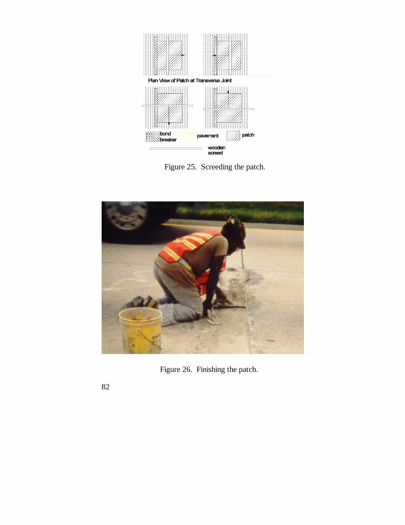
The surface of the patch should be troweled flush with thepavement surface. Vibration may be needed to make the workfinishable if the mix is too stiff. Partial-depth repairs are usuallysmall enough that a stiff board resting on the adjacent pavementcan be used as a screed. The material should be worked towardthe edges of the patch to establish contact and enhance bondingto the pavement, as shown in figure 25. At least two passesshould be made to ensure a smooth surface.
The repair surface must be hand-troweled to remove anyremaining minor irregularities, as shown in figure 26. The edgeof a repair located next to a transverse joint should be tooled toprovide a good reservoir for joint sealing. Extra mortar fromtroweling can be used to fill any saw overcuts at the patchcorners. Extra epoxy may also be used, or the saw overcutsmay be filled with joint sealant during the joint sealing process.
Partial-depth repairs typically cover only a small portion of thepavement surface and have little effect on skid resistance. However, the finished surface of the repair should match that ofthe pavement as closely as possible.
4.15 Curing
Curing is as important for partial-depth repairs as it is forfull-depth repairs. Since partial-depth repairs often have largesurface areas in relation to their volumes, moisture can be lostquickly. Improper curing can result in shrinkage cracks thatmay cause the repair to fail prematurely.
82
Figure 25. Screeding the patch.
Figure 26. Finishing the patch.

83
4.15.1 PCC Patching Materials
The most effective curing method when patching with PCCmaterials in hot weather is to apply a white-pigmented curingcompound as soon as water has evaporated from the repairsurface. The compound will reflect radiant heat while allowingthe heat of hydration to escape and will provide protection forseveral days. Moist burlap and polyethylene sheeting can alsobe used, but must be removed when the roadway is opened totraffic. In cold weather, insulating blankets or tarps can be usedto provide more rapid curing and to allow an earlier opening totraffic. The required curing time should be stated in the projectplans and specifications.
4.15.2 Proprietary Patching Materials
Some proprietary materials may require some form of moistcuring after the mix has stiffened (e.g., Five Star HP). Othersrequire the application of a curing compound (e.g., Pyrament505). Some proprietary repair materials may be air-cured (e.g.,SikaPronto 11). Epoxy and proprietary repair materials shouldbe cured as recommended by their manufacturers.
4.16 Joint Sealing
The final step in partial-depth spall repair is restoring the joints. When the recommended scored bond breaker has been used,the tear-off top strip should be removed, as shown in figure 27,and the selected sealant applied (see section 3.4.4). If a scoredbond breaker has not been used, joint restoration isaccomplished by resawing the joint to a new shape factor,sandblasting and airblasting both faces of the joint, inserting aclosed-cell backer rod, and applying the sealer. A minimum 1-week cure time should be allowed before joint sealing. Consult

84
Figure 27. Removing the tear-off topstrip of a joint bond breaker.
the Materials and Procedures for Repair of Joint Seals inConcrete Pavements–Manual of Practice for more informationon proper joint sealing practices (Evans and Romine, 1993b).
4.17 Cleanup Requirements
The material manufacturer's instructions should be consulted forinformation on cleaning equipment that has been used to mix,place, and finish their material. The cleaning solvent for mostcementitious materials is simply potable water. Someproprietary materials may require a special solvent; table 5shows which of several rapid-setting repair materials require aspecial cleaning solvent. Equipment must be cleaned

85
immediately after use so it will not contaminate the nextmaterial it contacts.
4.18 Opening to Traffic
Compressive strength requirements for paving concrete aregenerally specified at 20,700 kPa at 28 days. The repairconcrete should develop an equal or greater strength by thetime it receives traffic loadings. However, to minimize laneclosures, traffic loadings may be allowed on a patched areawhen the repair concrete has attained the minimum strengthneeded to ensure its structural integrity. The compressivestrength required for the opening of partial-depth patches totraffic may be lowered because of their lateral confinement andshallow depth.
The specifications of rapid-setting proprietary mixes should bechecked for recommended opening times. Cylinders or beamscan be tested for strength to determine what opening time willallow the repair material to develop enough strength. The timeto opening to traffic at 21oC for several rapid-setting partial-depth spall repair materials is shown in table 1.
4.19 Inspection
Quality control and inspection of the entire constructionprocess is crucial to the success of the repair. Field experiencehas shown that each step in the partial-depth spall repairprocess requires careful supervision and inspection. Aninspector must continually observe the various operations toensure that proper procedures are being followed. Appendix Dcontains detailed checklists for each step of the inspectionprocess.


87
5.0 Evaluating Partial-Depth PatchPerformance
It is good practice to monitor the performance of partial-depthpatches. By doing so, patch performance factors can bedetermined and used in comparing cost-effectiveness ofdifferent material-procedure patch treatments. One method forcalculating a performance factor is described in this chapter.
5.1 Data Required
To determine the effectiveness of a given patch type (material-procedure combination), field surveys must be conductedperiodically. The highway agency must record the survival lifefor all patches placed so that the mean service life can becalculated for the patch type. The main emphasis for the fieldsurvey is to verify the continued survival of the patches, todocument those that have failed, and to note distresses evidentin the surviving patches, which may indicate the failure mode ofthe patch.
For calculating the cost-effectiveness of a partial-depth spallrepair patching operation, it is necessary to estimate theexpected mean repair life of the patches. Table 8 shows onealternative for documenting survival information and generatinga mean repair life value for a situation when the time until repairis to be approximately 48 months. For a situation where thetime until repair would be approximately 24 months, themaximum service life recorded for each individual repair wouldbe 24 months.

88
Table 8. Sample patch performance data.
PatchNo.
Survival at Month No. Life at Month No.
1 3 6 12 18 24 36 48 24 36 48
1 U U U U U U U U 24 36 48
2 U U U U U U 24 24 24
3 U U U U U U U U 24 36 48
4 U U U U U U U U 24 36 48
5 U U U U U 18 18 18
6 U U U U U U U U 24 36 48
7 U U U U U U U U 24 36 48
8 U U U U U U U U 24 36 48
9 U U U U U U U U 24 36 48
10 U U U U 12 12 12
11 U U U U U U U U 24 36 48
12 U U U U U U U U 24 36 48
13 U U U U U 18 18 18
14 U U U U U U U U 24 36 48
15 U U U U U U 24 24 24
16 U U U U U 18 18 18
17 0 0 0
18 U U U U U U U 24 36 36
19 U U U U U 18 18 18
20 U U U U U 18 18 18
Mean Service Life 21 27 33

89
5.2 Calculations
The mean patch service life is calculated simply by averagingthe individual service life values recorded for each patch beingmonitored. The true mean service life cannot be determineduntil all of the repairs have failed.
The mean service life for the example shown in table 8 is 33months. This value is valid for calculating cost-effectivenessfor situations where the time until rehabilitation will beapproximately 48 months. For situations where the time untilrehabilitation will be 24 or 36 months, the mean service life forthe data shown in table 8 would be 21 or 27 months,respectively.


91
Appendix A
Material Testing Specifications
The following specifications for partial-depth spall repairmaterials are given as a guideline only and should be modifiedto reflect the conditions and requirements of a particularclimatic region or roadway classification.
A.1 Rapid-Setting Cementitious Concretes
The cementitious rapid-setting patching materials and somenon-flexible rapid-setting polymer materials (e.g., SikaPronto11) shall meet the following suggested guidelines foracceptance as approved materials.
Initial set time, minimum . . . . . . . . . . . . . . . . . . . . . . . 15 minCompressive strength
ASTM C 39, 3 hours . . . . . . . . . . . . . . . . . . . . . . 6.9 MPaCompressive strength
ASTM C 39, 24 hours . . . . . . . . . . . . . . . . . . . . 20.7 MPaBond strength of epoxy-resin systems
ASTM C 882 . . . . . . . . . . . . . . . . . . . . . . . . . . . . 1.4 MPaBond strength of concrete overlay and
patching materials, California test . . . . . . . . . . . . . 1.4 MPaFlexural strength
ASTM C 78 . . . . . . . . . . . . . . . . . . . . . . . . . . . . . 3.1 MPaFreeze-thaw resistance
ASTM C 666, Procedure A (150 cycles) . . . . . . 15 gramsScaling resistance
ASTM C 672 (100 cycles) . . . . . . . . . . . . . . . . . . . . . . . 5Surface abrasion resistance
California Test T550 . . . . . . . . . . . . . . . . . . . . . 25 grams

92
Thermal compatibilityASTM C 884 . . . . . . . . . . . . . . . . . . . . . . . . . . . . . . . pass
A.2 Rapid-Setting Flexible Polymer Concretes
The flexible polymer materials shall meet the followingsuggested guidelines for acceptance as approved materials.
Initial set time, minimum . . . . . . . . . . . . . . . . . . . . . . . 15 minBond strength of epoxy-resin systems
ASTM C 882 . . . . . . . . . . . . . . . . . . . . . . . . . . . . 1.4 MPaBond strength of concrete overlay and
patching materials, California test . . . . . . . . . . . . . 1.4 MPaFreeze-thaw resistance
ASTM C 666, Procedure A (150 cycles) . . . . . . . . . . 15 gScaling resistance
ASTM C 672 (100 cycles) . . . . . . . . . . . . . . . . . . . . . . . 5Surface abrasion resistance
California Test T550 . . . . . . . . . . . . . . . . . . . . . . . . . 25 gThermal compatibility
ASTM C 884 . . . . . . . . . . . . . . . . . . . . . . . . . . . . . . . pass
A.3 Bituminous Materials
Bituminous patching materials shall meet the agency'ssuggested guidelines for acceptance as approved materials. Tests for workability, stripping, drainage, and cohesion arehighly recommended. Additional tests suggested by otheragencies and proprietary material manufacturers may also beused. Consult Appendix A of Materials and Procedures forthe Repair of Potholes in Asphalt Pavements–Manual ofPractice for more information on compatibility and acceptancetests for bituminous cold mix materials (Wilson and Romine,1993).

93
Appendix B
Sample Cost-Effectiveness Calculations
This appendix contains sample worksheets for cost-effectiveness calculations. Different material and procedurecombinations illustrate the financial differences betweenpatching operations.
When using the examples in the following sections, it isimportant to remember that crew size and productivity differgreatly among agencies. These examples are fictitious and theironly purpose is to show how the worksheets are used whencompleting them with the information relevant to a particularagency.
Each example considers the placement of 200 partial-depthpatches with an average finished patch length of 457 mm, widthof 229 mm, and depth of 51 mm. Therefore, for all examples,the expected total volume of the finished patches is 1.07 m3. The average daily wage for the maintenance worker is assumedto be $120 in each example. Other data vary from example toexample.
Calculation of the amount of materials needed, such as apatching material, bonding agent, joint bond breaker, or curingcompound, is not demonstrated. The examples assume thatagencies are already familiar with these calculations based onthe number, length, width, and depth of the patches, and atypical waste factor for each material.

94
B.1 Example 1
Example 1 considers the placement of 200 material "A" patchesusing the saw-and-patch procedure. Material, labor, andequipment costs can be directly entered on the cost-effectiveness worksheet. However, the average dailyproductivity, the estimated number of days for the patchingoperation, and the partial-depth patch survival rate require afew advance calculations.
In calculating the average daily productivity and estimatednumber of days for patching, the examples assume that the lastpatch will be placed at the latest possible time and thatpreparation will stop when there is enough time to place the lastpatch. Therefore the patch preparation rate will control thenumber of patches that can be placed per day. The examplealso assumes that a crew of seven places seven patches perhour, and that the average patch volume is 0.005 m3.
Patches prepared per hour = 7Work hours per day = 8Material cure time = 4 hrNumber of hours available for preparation
and placement (work hours - cure hours) = 4 hrAverage preparation rate
(7 patches/hr) × (0.006 m3/patch) = 0.042 m3/hrAverage daily productivity
4 hr × 0.042 m3/hr × (1 patch/0.006 m3) = 28 patchesEstimated number of days for patching (rounded up)
200 / 28 = 8 days
The mean patch survival life is estimated at 50 months for asituation where a rehabilitation will be placed in approximately60 months. Figure B-1 shows the completed cost-effectivenessworksheet for this example.

95
ESTIMATE OF PROJECT SIZE OR SEASONAL PARTIAL-DEPTH PATCHING NEEDS
amount unitsExpected Number of Patches 200 (A) Average Finished Patch Length 457 mm (B1)Average Finished Patch Width 229 mm (B2)Average Finished Patch Depth 51 mm (B3)Expected Total Volume of Finished Patches[(B1 × B2 × B3 × A) ÷ 109] 1.07 m3 (C)
MATERIAL COSTS (e.g., cold mix, cement, aggregate, sand, bondingagent, joint bond breaker, curing agent, etc.)
Material 1 = Patching Material "A"Material 1 Purchase Cost 172 $/m3 (D1)Expected Material 1 Needs 1.23 m3 (E1)Material 1 Shipping Cost 0 $ (F1)
Total Material 1 Cost [(D1 × E1) + F1] 211 $ (G1)
Material 2 = Bonding AgentMaterial 2 Purchase Cost 12 $/L (D2)Expected Material 2 Needs 56.2 L (E2)Material 2 Shipping Cost 0 $ (F2)
Total Material 2 Cost [(D2 × E2) + F2] 675 $ (G2)
Material 3 = Joint Bond BreakerMaterial 3 Purchase Cost 1.075 $/m (D3)Expected Material 3 Needs 152.5 m (E3)Material 3 Shipping Cost 0 $ (F3)
Total Material 3 Cost [(D3 × E3) + F3] 164 $ (G3)
Material 4 = Curing CompoundMaterial 4 Purchase Cost 2.6 $/L (D4)Expected Material 4 Needs 7.7 L (E4)Material 4 Shipping Cost 0 $ (F4)
Total Material 4 Cost [(D4 x E4) + F4] 20 $ (G4)
Figure B-1. Example 1 cost-effectiveness worksheet.

96
LABOR COSTSamount units
Number in Repair Crew 9 (H) Average Daily Wage per Person 120 $/day (I)
Number in Traffic Control Crew 2 (J)
Average Daily Wage per Person 120 $/day (K)
Supervisor Daily Wage 200 $/day (L)
EQUIPMENT COSTS
Material Truck 20 $/day (M)
Traffic Control Trucks and Signs 150 $/day (N)
Patch Preparation Equipment(e.g., concrete saw, jackhammer, 225 $/day (O1)milling machine, waterblaster) 60 $/day (O2)
Cleaning Equipment 350 $/day (P1)
(e.g., sandblaster, airblaster) 0 $/day (P2)
Mixing Equipment 35 $/day (Q1)(e.g., mortar mixer, Jiffy mixer) 0 $/day (Q2)
Consolidation/Compaction Equipment(e.g., pencil vibrator, vibrating screed, vibratory roller) 20 $/day (R)
Extra Equipment Truck 0 $/day (S)
Miscellaneous Equipment 0 $/day (T1)
(e.g., spray-injection machine, 0 $/day (T2)
joint sealing equipment, etc.)
Figure B-1. Example 1 cost-effectiveness worksheet(continued).

97
SUMMARY COSTSamount units
Total Material Cost(G1 + G2 + G3 + G4 + ...) 1070 $ (U)
Total Daily Labor Cost[(H × I) + (J × K) + L] 1520 $/day (V)
Total Equipment Cost[M + N + (O1 + O2 + ...) + (P1 + P2 + ...) + (Q1 + Q2 + ...) + R + S + (T1 + T2 + ...)] 860 $/day (W)
User Delay Costs 1000 $/day (X)
Average Daily Productivity 28 patches/day (Y)
Estimated Number of Daysfor Patching Operation(A ÷ Y) 8 days (Z)
Total Patching Operation Cost[U + {Z × (V + W + X)}] 28,110 $ (AA)
Expected Mean Life for Partial-DepthPatches1 50 months (BB)
Time to Pavement Rehabilitation 60 months (CC)
Effective Patching Cost Over Time[AA × (CC/BB)] 33,732 $ (DD)
1 Until expected mean life values have been determined, agency experienceshould be applied. See chapter 5 for calculation examples.
Figure B-1. Example 1 cost-effectiveness worksheet(continued).

98
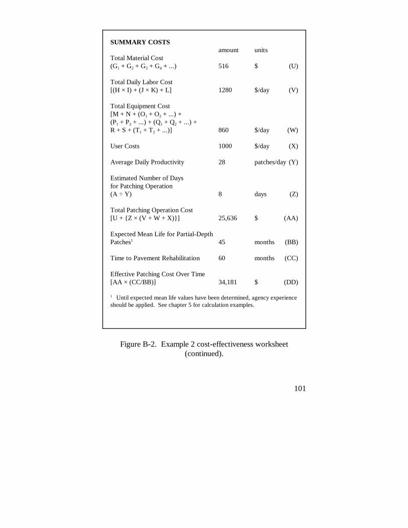
B.2 Example 2
Example 2 considers the placement of 200 material "B" patchesusing the chip-and-patch procedure. As in example 1, material,labor, and equipment costs can be directly entered on the cost-effectiveness worksheet. However, the average dailyproductivity, the estimated number of days for the patchingoperation, and the partial-depth patch survival rate require afew advance calculations as well.
The same assumptions made in example 1, regarding thecalculation of the average daily productivity and estimatednumber of days for patching, are made here. This exampleassumes that sawing equipment will be needed to re-establishthe joints, and that the chip-and-patch preparation process willhave the same productivity as the saw-and-patch preparationprocess, because the time needed for jackhammering will takeup the time not needed for sawing.
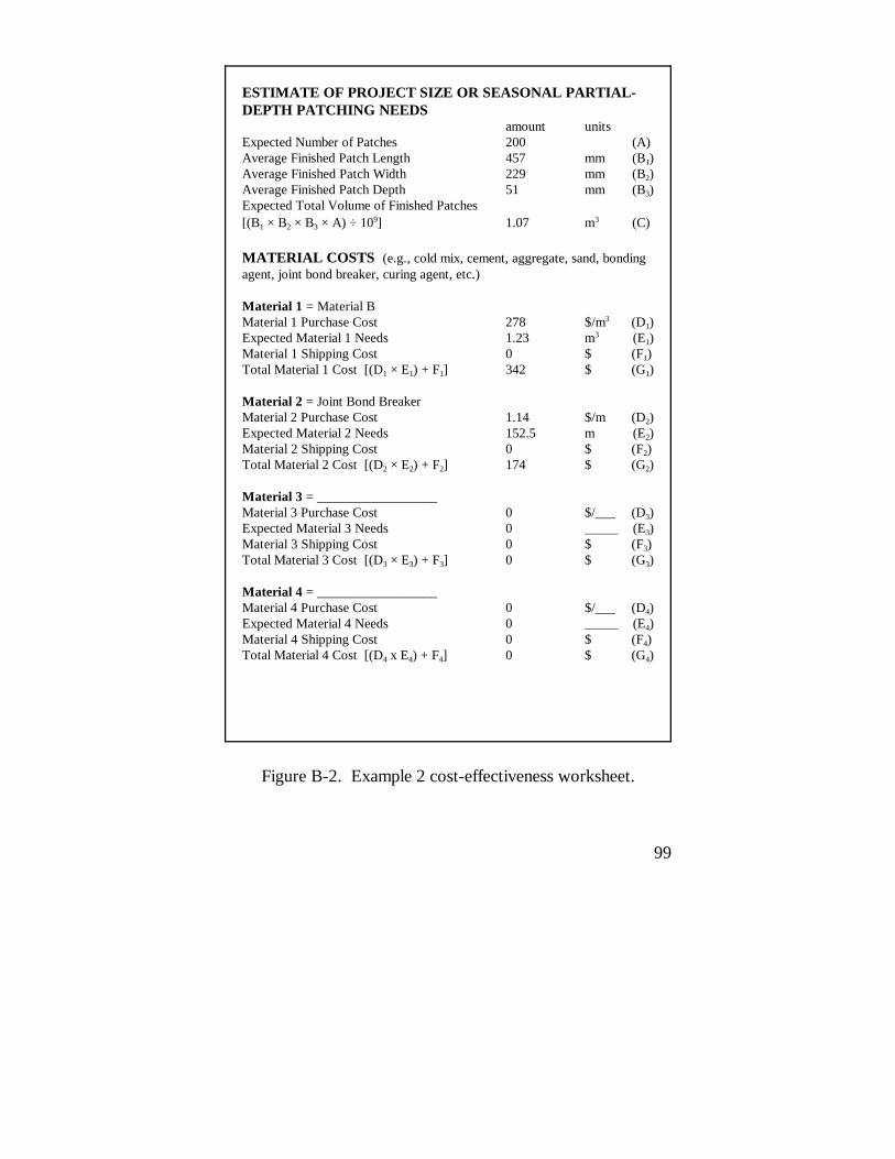
The mean patch survival life is estimated at 45 months for asituation where a rehabilitation will be placed in approximately60 months. Figure B-2 shows the completed cost-effectivenessworksheet for this example.
99
ESTIMATE OF PROJECT SIZE OR SEASONAL PARTIAL-DEPTH PATCHING NEEDS
amount unitsExpected Number of Patches 200 (A) Average Finished Patch Length 457 mm (B1)Average Finished Patch Width 229 mm (B2)Average Finished Patch Depth 51 mm (B3)Expected Total Volume of Finished Patches[(B1 × B2 × B3 × A) ÷ 109] 1.07 m3 (C)
MATERIAL COSTS (e.g., cold mix, cement, aggregate, sand, bondingagent, joint bond breaker, curing agent, etc.)
Material 1 = Material BMaterial 1 Purchase Cost 278 $/m3 (D1)Expected Material 1 Needs 1.23 m3 (E1)Material 1 Shipping Cost 0 $ (F1)
Total Material 1 Cost [(D1 × E1) + F1] 342 $ (G1)
Material 2 = Joint Bond BreakerMaterial 2 Purchase Cost 1.14 $/m (D2)Expected Material 2 Needs 152.5 m (E2)Material 2 Shipping Cost 0 $ (F2)
Total Material 2 Cost [(D2 × E2) + F2] 174 $ (G2)
Material 3 = __________________Material 3 Purchase Cost 0 $/___ (D3)Expected Material 3 Needs 0 _____ (E3)Material 3 Shipping Cost 0 $ (F3)
Total Material 3 Cost [(D3 × E3) + F3] 0 $ (G3)
Material 4 = __________________Material 4 Purchase Cost 0 $/___ (D4)Expected Material 4 Needs 0 _____ (E4)Material 4 Shipping Cost 0 $ (F4)
Total Material 4 Cost [(D4 x E4) + F4] 0 $ (G4)
Figure B-2. Example 2 cost-effectiveness worksheet.

100
LABOR COSTSamount units
Number in Repair Crew 7 (H) Average Daily Wage per Person 120 $/day (I)
Number in Traffic Control Crew 2 (J) Average Daily Wage per Person 120 $/day (K)
Supervisor Daily Wage 200 $/day (L)
EQUIPMENT COSTS
Material Truck 20 $/day (M)
Traffic Control Trucks and Signs 150 $/day (N)
Patch Preparation Equipment(e.g., concrete saw, jackhammer, 225 $/day (O1)milling machine, waterblaster) 60 $/day (O2)
Cleaning Equipment 350 $/day (P1)
(e.g., sandblaster, airblaster) 0 $/day (P2)
Mixing Equipment 35 $/day (Q1)(e.g., mortar mixer, Jiffy mixer) 0 $/day (Q2)
Consolidation/Compaction Equipment(e.g., pencil vibrator, vibrating screed, vibratory roller) 20 $/day (R)
Extra Equipment Truck 0 $/day (S)
Miscellaneous Equipment 0 $/day (T1)(e.g., spray-injection machine, 0 $/day (T2)joint sealing equipment, etc.)
Figure B-2. Example 2 cost-effectiveness worksheet(continued).
101
SUMMARY COSTSamount units
Total Material Cost(G1 + G2 + G3 + G4 + ...) 516 $ (U)
Total Daily Labor Cost[(H × I) + (J × K) + L] 1280 $/day (V)
Total Equipment Cost[M + N + (O1 + O2 + ...) + (P1 + P2 + ...) + (Q1 + Q2 + ...) + R + S + (T1 + T2 + ...)] 860 $/day (W)
User Costs 1000 $/day (X)
Average Daily Productivity 28 patches/day (Y)
Estimated Number of Daysfor Patching Operation(A ÷ Y) 8 days (Z)
Total Patching Operation Cost[U + {Z × (V + W + X)}] 25,636 $ (AA)
Expected Mean Life for Partial-DepthPatches1 45 months (BB)
Time to Pavement Rehabilitation 60 months (CC)
Effective Patching Cost Over Time[AA × (CC/BB)] 34,181 $ (DD)
1 Until expected mean life values have been determined, agency experienceshould be applied. See chapter 5 for calculation examples.
Figure B-2. Example 2 cost-effectiveness worksheet(continued).


103
Appendix C
Material and Equipment SafetyPrecautions
This appendix contains some common-sense safety precautionsfor using materials and equipment in the partial-depth spallrepair process. These precautions are not a complete list, norwill they apply to all materials and equipment. It is essentialthat the highway agency obtain, review, and follow safetydata sheets for all materials and all equipment. The agencyshould develop a safety training program that will properlyinstruct highway workers in the safe use of all materials andequipment involved in partial-depth spall repair.
C.1 Materials
Some common-sense precautions for the safe use of manyrapid-setting materials, admixtures, bonding agents, curingcompounds, and solvents include the following:
! To avoid skin contact during mixing, placing, andcleaning:ý Wear long-sleeved shirts.ý Wear long pants.ý Wear gloves.ý Wear steel-toed boots.
! To avoid ingestion during mixing, placing, and cleaning:ý Wear eye protection.ý Wash hands (even if gloves have been worn) before
handling anything that will go into the mouth (e.g.,

104
lunch containers, silverware, food, drinks, tobacco,gum, etc.).
ý Wash hands before touching the face, eyes, nose,mouth, or any other part of the body.
ý Avoid inhaling fumes and vapors (use respirators ifrequired).
ý Use in well-ventilated areas.
! To avoid creating additional toxic vapors or fumes,never combine any substances unless following thespecific instructions of the manufacturers of thosesubstances. This includes combination by mixing, bycleaning, by adjacent placement, by contamination, etc.
C.2 Equipment
Some common-sense precautions for the safe use of typicalpartial-depth spall repair equipment include the following:
! Wear eye protection, gloves, long-sleeved shirts, longpants, and steel-toed boots during sawing,jackhammering, sandblasting, airblasting, milling,waterblasting, spray injection, and any other operationthat could injure the skin, eyes, limbs, etc.
! Use ear protection during sawing, jackhammering,sandblasting, airblasting, milling, waterblasting, sprayinjection, and any other operation that is loud and couldpermanently damage the hearing.

105
Appendix D
Inspection Checklists for Construction
This appendix is intended for inspectors of the partial-depthspall repair process. It contains discussions of planning,equipment, and procedures crucial to successfully completing apartial-depth spall repair project. Checklists pertaining to eachstep of the process–including planning, equipment, materialmixing, patch preparation, material installation, and safetyprecautions–are provided.
D.1 Plans and Specifications
Plans must be prepared and distributed to the inspector and thesupervisor of the installation crew. The plans must contain thefollowing information:
G 1. Project layout (including stationing, slab lengths,location of spalls to be repaired, etc.).
G 2. Original pavement material type.G 3. Location and type of any pre-patching repairs
required.G 4. Required patch dimensions.G 5. Required joint reservoir dimensions.
Specifications may be based either on adherence to designatedprocedures or on achieving a quality end-product. They mayalso combine the two. Procedure-based specifications mustcontain the following information:
G 1. Delivery and storage requirements.G 2. Equipment requirements.G 3. Material requirements.

106
G 4. Material mixing procedure requirements.G 5. Patch preparation procedure requirements.G 6. Installation procedure requirements.G 7. Weather condition limitations.G 8. Traffic control requirements.G 9. Material disposal requirements.G 10. Safety requirements.
End-result specifications must contain the followinginformation:
G 1. Delivery and storage requirements.G 2. Required results of mixing procedures and
acceptance-rejection criteria.G 3. Required results of each preparation procedure
and acceptance-rejection criteria.G 4. Required results of the installation process and
acceptance-rejection criteria.G 5. Weather condition limitations.G 6. Traffic control requirements.G 7. Material disposal requirements.G 8. Safety requirements.
Most projects combine procedure-based and end-resultspecifications. The following inspection process is based ontheir combination.
D.2 Equipment
All equipment must be inspected and approved before theproject begins, as well as during mixing, patch preparation,patch installation, and sealant installation. A list of proposedequipment should be submitted before installation for approval. During the pre-installation inspection, the inspector shouldcheck all equipment, ensuring that each piece meets the project

107
specifications. Suitability of equipment for mixing and placing aparticular repair material can be confirmed by contacting thematerial manufacturer.
The condition and effectiveness of each piece of equipmentshould be checked at the beginning of each day of patchpreparation, mixing, and installation.
D.3 Material Quality
The inspector must confirm that the patching materials, jointbond breaker, bonding agent, curing compound, and so on arefrom the agency's "approved list" or are from a certified plant,and that samples of the materials have been submitted to theagency's laboratory for testing. The material manufacturer'srecommendations for storage and shelf life should also bechecked. Materials that are not stored properly or that are oldmay not meet quality standards.
D.4 Field Installation
After all required slab stabilization and other prepatchingrehabilitation have been completed and approved, the partial-depth spall repair process can begin. Inspector(s) andsupervisor(s) should meet before work begins to discuss thefollowing subjects:
G 1. Exact locations and dimensions of all spalls to bepatched. (The boundaries should be clearlymarked.)
G 2. Traffic control requirements and lane closuretime limitations.

108
G 3. Methods for preparing and cleaning repair areas,for mixing and placing the repair materials, andfor reinstalling a joint sealant system.
G 4. Recommended accessory materials andinstructions for their use.
G 5. Material properties and working tolerances;G working times.G time to traffic at the anticipated mixing and
placement temperatures.G moisture conditions allowable during
placement.G temperatures allowable during mixing and
placement.G 6. Mixing times, components, proportions, and
sequences.G 7. Criteria for approval of all cleaning and
installation equipment and processes.G 8. Criteria for final approval of the repair work.G 9. Any localized variations from the specified
methods.G 10. Procedures in the event of hot, cold, and/or wet
weather.G 11. Material disposal requirements.G 12. Safety requirements for all equipment and
procedures and MSDS’s.
D.5 Preparing the Repair Area
Patch preparation includes removing deteriorated concrete andold sealant in the adjacent joint, final cleaning, installing thejoint bond breaker, and applying the bonding agent. Thefollowing inspection checklist can be used to ensure that spallpreparation is completed properly. Not all of these patchpreparation procedures are used at one time.

109
G 1. Sounding:G a solid steel rod, chain, or ball-peen hammer
is used to sound the spalled area before andafter the deteriorated concrete is removed.
G all deteriorated concrete is removed usingthe specified method until all parts of therepair area yield a clear ringing sound whenthey are sounded.
G 2. Sawing:G the concrete saw is establishing straight,
vertical patch boundaries to the requireddepth, where specified.
G the concrete saw is removing the requiredamount of concrete and sealant in anyadjacent joint.
G the concrete saw is uniformly cutting to theproper width and depth. (Depth and widthcan be checked quickly using a metaltemplate.)
G 3. The water-wash equipment is removing allsawing and/or waterblasting slurry from therepair area before it dries.
G 4. Jackhammering:G jackhammers of the specified weight are
removing all deteriorated concrete to thespecified depth, without fracturing the soundconcrete below the repair or undercutting orspalling any sawed boundaries.
G chiseling is begun in the center of the repairarea and proceeds outward.
G only light jackhammers are used near thepatch boundaries.
G if patch boundaries have not been sawed, thehammering is producing rough, verticaledges (not scalloped edges into which therepair material will have to be feathered).

110
G spade bits (not gouge bits) are being used.G jackhammers are being operated at an angle
less than 45 degrees from the vertical.G 5. Milling:
G the carbide-tipped milling machine isremoving all deteriorated concrete to thespecified minimum depth.
G any material that remains at the patchcorners is removed by light jackhammeringor sawing.
G whenever possible, the milling machine isoriented such that the rounded edges of themilling hole are parallel to the direction oftraffic.
G if this is not possible, the rounded edges arechipped into straight, vertical edges.
G edge spalling is minimized.G 6. Waterblasting:
G a protective shield has been built around therepair area before waterblasting if traffic ispassing in the next lane.
G the waterblasting equipment has beencalibrated to remove the specified depth ofconcrete.
G operation parameters are not changedthroughout the remainder of the projectunless the concrete changes (e.g., theaggregate hardness differs from onepavement section to another).
G the waterblasting equipment is removing alldeteriorated concrete to the required depth,and is producing neat, vertical faces at thepatch boundaries.
G waterwashing equipment is used to wash thewaterblasting slurry from the repair areabefore it dries.

111
G 7. A full-depth repair is used if at any point in thepatch preparation process, the deteriorated areaof concrete is found to be deeper than the topthird of the pavement slab, or if reinforcing barsor mesh are encountered.
G 8. Handtools and shovels are being used toremove all loose material, when preparing thepatch under adverse conditions.
G 9. Sandblasting: G the sandblasting equipment is uniformly
cleaning the faces of the repair area. Thistypically requires that the nozzle be held 25mm to 50 mm from the pavement and thatseveral passes be made.
G no old sealant, oil, or dried sawing and/orwaterblasting slurry remains in the repairarea.
G the sandblasting equipment does notintroduce oil or moisture to the repair area.
G after sandblasting, the entire surface area ofthe patch hole contains freshly exposedconcrete.
G 10. Airblasting:G the airblasting equipment is removing all dirt,
dust, old sealant, and sand from the dryrepair area.
G the airblaster does not introduce oil ormoisture to the repair area.
G after airblasting, the repair area is clean anddry.
G 11. Compressed air is removing all old sealant,sand, dirt, and dust from the pavement surfaceso that it cannot re-enter the repair area,especially on windy days or when traffic passesnext to the cleaned repair areas.

112
G 12. Recleaning:G the repair area is re-checked for cleanliness
just before material placement.G cleaned repair areas that have been
recontaminated by rain, dew, dirt, or oil arecleaned again in a manner that restores theoriginal cleanliness. This may requiresandblasting and airblasting, or merelyairblasting.
G cleaned repair areas that are left overnightare, at a minimum, airblasted again.
G 13. The repair area is allowed to dry if a moisture-sensitive repair material will be used. (Water onthe surface of the repair area during materialinstallation may severely reduce the ability of thematerial to bond to the surface, depending onthe material type. Watch for heavy dew thatmay collect in the repair area and remain afterthe surface is dry.)
G 14. Scored bond breaker:G a strip of scored bond breaker is placed at
the joint-patch interface 25 mm deeper thanthe repair, and extends at least 50 mm to 75mm beyond the repair boundaries.
G the bond breaker is either of the appropriateheight or is stacked and latex-caulked whennecessary so that there are no gaps throughwhich the repair material can flow.
G a true, straight joint line is maintained wheninstalling the bond breaker.
G 15. Bonding agent:G the bonding agent sprayer or brush is
applying a thin layer of bonding agentuniformly over the repair area.
G the bonding agent is still tacky when therepair material is placed.

113
G 16. Safety:G all required operator safety equipment is in
use.G all required safety precautions are followed.
D.6 Installing the Patch
Patch installation includes mixing, placing, and finishing thepatching material. The following inspection checklist can ensure that patch installation is completed properly.
D.6.1 Mixing
During the mixing of the repair materials, the following itemsshould be regularly checked to ensure that they meet therequirements. Not all rapid-setting partial-depth spall repairmaterials require mixing.
G 1. All mixing equipment is clean before use. Some material manufacturers may recommendpre-wetting the mixer so no water is lost whenmixing the first batch.
G 2. The water used for mixing is clean.G 3. The mixing operation results in a consistently
mixed material.G 4. The material is not over- or undermixed.G 5. Any spilled material is removed from the
pavement surface.G 6. The mixing temperature is as recommended.
Warm water or ice water is used to raise orlower the mix temperature as needed.
G 7. Mixing time, mix components, mixproportions, and mix sequences are carefullyfollowed.

114
G 8. The mixing equipment is cleaned with thesolvent specified by the materialmanufacturer immediately after use.
G 9. The mixing of the bonding agent and repairmaterial is scheduled such that the bondingagent is tacky when the repair material is placed.
G 10. Disposal of all wasted materials and solventsfollows the manufacturer's specifications andState ordinances.
G 11. All required operator safety equipment is inuse.
G 12. All required safety precautions are followed.
Material that has begun to set during mixing, or material that istoo wet, should not be placed. It should be discarded, and themixing process begun again; a retarding agent may need to beadded. The mixing time or amount of water may also need tobe adjusted.
D.6.2 Placement
During placement, the following items should be regularlychecked to ensure that they meet the requirements. Not allsteps will be required for all materials.
G 1. The repair material is placed in a clean repairhole, under the specified moisture conditions,using the specified placement methods.
G 2. The bonding agent thoroughly coats thebottom and sides of the repair area, but does notcollect in any pockets.
G 3. The material is placed when the bonding agentis still tacky.
G 4. The repair hole is slightly overfilled with therepair material for those materials that requireconsolidation or compaction.

115
G 5. A shovel is used (not a wheelbarrow or abucket) to place repair materials that containaggregate, so that segregation does not occur.
G 6. The repair material is not placed below orabove its permissible placement temperaturerange.
G 7. Deep repairs are placed in lifts to control heatdevelopment, when specified.
G 8. A pencil vibrator or handtools are used torelease trapped air from the mix.
G 9. The vibrator is held at 15 to 30 degrees fromthe vertical, and is moved through the concreteby lifting it up and down to vibrate the entirearea until the mix stops settling, air bubbles nolonger emerge, and a smooth layer of mortarappears at the surface.
G 10. A bituminous cold mix patch is compacted torelease trapped air using a vibratory roller orplate until it is level with the pavement.
G 11. Disposal of all wasted materials and solventsfollows the manufacturer's specifications andState ordinances.
G 12. Field testing is conducted as appropriate for thepatching materials, such as testing beams orcylinders for strength and quality control.
G 13. All required operator safety equipment is inuse.
G 14. All required safety precautions are followed.

116
D.6.3 Material Finishing and Curing
During finishing, the following items should be regularlychecked to ensure that they meet the requirements. Not allsteps will be required by all materials.
G 1. The repair material is troweled level with thepavement before finishing.
G 2. The repair material is screeded with a stiffboard, using at least two passes.
G 3. The repair material is worked toward the patchedges to enhance bonding with the existing slab.
G 4. The saw cuts are filled with excess mortar orepoxy, or are filled with joint sealant during thejoint resealing process.
G 5. The patch surface is finished to match thesurface of the surrounding pavement.
G 6. Appropriate curing methods are used so thatshrinkage cracks do not develop.G curing agents are applied uniformly to the
patch.G the water used for curing is clean.G insulating covers and longer cure times
are used at cooler temperatures, as specifiedby the material manufacturer.
G 7. Disposal of wasted repair material, curingcompound, and cleaning solvents follows themanufacturer's specifications and Stateordinances.
G 8. Traffic is not allowed on the pavement until thematerial has developed the strength necessary tocarry traffic without being damaged.
G 9. All required operator safety equipment is inuse.
G 10. All required safety precautions are followed.

117
D.6.4 Joint Resealing
Consult the Materials and Procedures for Repair of Joint Sealsin Concrete Pavements–Manual of Practice for informationregarding the inspection of the joint resealing process (Evansand Romine, 1993b). In addition to the inspection criteria listedin that manual, when using a scored bond breaker, the followingcriteria should be met:
G 1. Joint resealing or filling is conducted after aminimum curing time of 1 week.
G 2. Immediately before joint resealing or filling, thetop strip is torn off of the scored bond breaker,leaving a uniform, clean, dry reservoir.
G 3. Before resealing or filling the joints, low-pressure air cleaning is used if dust or dirt hasblown into the joints after removal of the tear-away top strip.
D.7 Final Inspection
During installation and before approval, the partial-depthpatches should be individually inspected, ensuring that the patchmeets the highway agency's criteria, and noting the presenceand severity of any distresses. The final inspection shouldinclude the following:
G 1. The patch is bonded firmly to the existingpavement and has not separated from thesidewalls.
G 2. The patch is level with the surface of theexisting pavement.
G 3. The patch contains no cracks (other than finehairline shrinkage cracks) or bubbles.

118
G 4. All material that has spilled on the pavement hasbeen removed.
G 5. No debris has been left on the pavement.
Consult the Materials and Procedures for Repair of Joint Sealsin Concrete Pavements–Manual of Practice for informationregarding final inspection of the joint sealant system (Evans andRomine, 1993b).

119
Appendix E
Partial List of Material and EquipmentSources
This appendix contains a partial listing of material andequipment manufacturers. Addresses and phone numbers areprovided for manufacturers and/or suppliers who can providethe inquirer with information regarding products, installationpractices, safety procedures, costs, and local suppliers.
MSDS’s, where applicable, should be available from allmanufacturers. Information regarding the safe use of allmaterials and equipment should be carefully followed to ensureworker safety and the safety of the traveling public.
Inclusion of a particular material, piece of equipment, orsupplier in this list does not serve as an endorsement of thatmaterial, equipment, or supplier. Likewise, omission from thislist is not intended to carry negative connotations for thematerials, pieces of equipment, and suppliers omitted.
E.1 Partial-Depth Patching Materials
E.1.1 Manufacturers of Cementitious Concretes
Euclid Chemical Company19218 Redwood RoadCleveland, OH 44110-2799(216) 531-9222(800) 321-7628www.euclidchemical.com

120
Five Star Highway Products, Inc.425 Stillson RoadFairfield, CT 06430(203) 336-7900
Fosroc International Limited55 Skyline DrivePlanview, NY 11802(516) 935-9100www.fosroc.com
Hartline Products Company, Inc.2186 Noble RoadCleveland, OH 44112(216) 451-6573
L&M Construction Chemicals, Inc.14851 Calhoun RoadOmaha, NE 68152(402) 453-6600
Master Builders23700 Chagrin BoulevardCleveland, OH 44122-5554(800) 628-9990www.masterbuilders.com
United States Gypsum Company Industrial Gypsum Division125 South Franklin St.Chicago, IL 60606-4678(312) 606-4000(800) 874-4968www.usg.com

121
E.1.2 Manufacturers of Polymer Concretes
Accelerated Systems Technology Corporation140 Chaparral CourtSuite 100Anaheim, CA 92808(714) 263-9074
HC Epoxy Company, Inc.862 East 19th StreetTucson, AZ 85719(602) 624-7929
GeoChem, Inc.P.O. Box 838Renton, WA 98057-0838(425) 227-9312www.geocheminc.com
Pyrament/Lone Star Industries, Inc.340 North Sam Houston Parkway, EastHouston, TX 77060(800) 633-6121
Sika Corporation201 Polito AvenueLyndhurst, NJ 07071(201) 933-8800www.sika.com
The Burke CompanyP.O. Box 5818San Mateo, CA 94402(415) 349-7600(800) 423-9140

122
Thoro System ProductsDepartment PWM7800 N.W. 38th StreetMiami, FL 33166
E.1.3 Manufacturers of Bituminous Materials
Unique Paving Materials Corporation3993 E. 93rd StreetCleveland, Ohio 44105-4096(800) 441-4881www.upm.com
E.1.4 Manufacturers of Bonding Agents
Master Builders23700 Chagrin BoulevardCleveland, OH 44122-5554(800) 628-9990www.masterbuilders.com
The Burke Company6433 East 30th StreetIndianapolis, IN 46219(317) 543-4475
E.2 Partial-Depth Patching Equipment
E.2.1 Manufacturers of Sawing Equipment
Cimline, Inc.2601 Niagara LaneMinneapolis, MN 55447(800) 328-3874www.cimline.com

123
Target Products Division4320 Clary BoulevardKansas City, MO 64130(816) 923-5040
Vermeer Manufacturing CompanyRoute 2P.O. Box 200Pella, IA 50219(515) 628-3141
E.2.2 Manufacturers of Spray-Injection Equipment
Zimmerman Equipment Corporation1000 South Thompson LaneP.O. Box 110098Nashville, TN 37211(615) 833-5705
Wildcat Manufacturing Company, Inc.Highway 81P.O. Box 523Freeman, SD 57029(605) 925-4512
Rosco Manufacturing Company1001 S.W. First St.P.O. Box BMadison, SD 57042(605) 256-0240
Duraco Industries, Inc.P.O. Box 6127Jackson, MS 39288-6127(601) 932-2100

124
E.2.3 Manufacturers of Waterblasting Equipment
FLOW Services23500 64th StreetKent, WA 98032(800) 446-3569, Ext. 900
E.2.4 Manufacturers of Milling Equipment
Cedarapids, Inc.916 16th Street, N.E.Cedar Rapids, IA 52402(319) 363-3511
Vermeer Manufacturing CompanyRoute 2P.O. Box 200Pella, IA 50219(515) 628-3141
E.2.5 Manufacturers of Jackhammers
Atlas Copco Berema, Inc.161 Lower Westfield RoadHolyoke, MA 01040(800) 284-2373(413) 536-0600
E.2.6 Manufacturers of Compacting Equipment
Stone Construction Equipment, Inc.Corporate Offices/Northern Manufacturing Plant32 East Main StreetP.O. Box 150Honeoye, NY 14471-0150(800) 888-9926

125
Glossary
Admixture–A substance added to a mixture during mixing.
Adverse patching conditions–Climatic conditions in which theair temperature is below 40oF (4oC) and the repair area issaturated with surface moisture.
Bonding agent–A substance that promotes good bondingbetween the pavement surface and a repair material placed onthe surface.
Breaking and seating–The breaking and compaction of acontinuously-reinforced concrete pavement, reducing theamount of reflective cracking in the overlay.
Calcium aluminate concrete–A high alumina (Al2O3)cementitious concrete.
Chemical conversion–A chemical process that results in achange in the nature, structure, or properties of a substance.
Compact–To release trapped air and reduce volume usingcompression.
Compression failure–The crushing of a repair due to theexpansion of the surrounding pavement during freeze-thawcycles.
Compression recovery–The property of being able to regainoriginal shape and volume after being compressed.
Compressive strength–The maximum compressive stress amaterial can withstand before failure.

126
Compressive stress–A stress that causes an elastic body toshorten in the direction of the applied force and that causes aninelastic body to rupture.
Consolidate–To release trapped air from fresh concrete mix byusing vibration.
Cracking and seating–The breaking and compacting of a plainconcrete pavement, reducing the amount of reflective crackingin the overlay.
D-cracking–Durability cracking; a pattern of cracks runningparallel and close to a joint or linear crack caused by freeze-thaw expansion of large, nondurable aggregate.
Debonding–The partial or complete loss of bond between twomaterials, such as between a patch and a slab.
Diamond grinding–A surface restoration in which patterns arecut into hardened concrete with closely spaced diamond sawblades to correct surface distresses.
Epoxy concrete–A polymer concrete containing epoxy resin (aflexible, thermosetting resin made by polymerization of anepoxy compound).
Feathering–The thin placement of patching materials becauseof curved or angled patch edges that do not allow adequatedepth of placement.
Free sulfate–A chemical group containing sulfur and oxygen(-SO4) that is free to react chemically with other chemicalgroups.

127
Full-depth spall repair–The removal of an area of deterioratedconcrete the entire depth of a pavement slab, and itsreplacement with a repair material along with the restoration ofload transfer devices.
Full lane-width patch–A patch that extends the entire width ofa lane.
Gouge bit–A curved chisel tip used in jackhammering that isnot recommended for partial-depth spall repair.
Gypsum-based concrete–A cementitious concrete that containsgypsum, a common sulfite mineral.
Heat of hydration–The heat given off when molecular water isincorporated into a complex molecule with molecules such asthose found in cementitious mixes.
High alumina concrete–A cementitious concrete that containsa higher amount of alumina (the native form of aluminumoxide) than regular concrete.
High early-strength materials–Patching materials that gainhigh strength levels early in their curing period.
High molecular weight methacrylate concrete–A cementitiousconcrete containing high molecular weight methacrylate, anacrylic resin or plastic made from a derivative of methacrylicacid (C4H6O2).
Hydration rate–The rate at which molecular water isincorporated into a complex molecule with molecules such asthose found in cementitious mixes.
Incompressible–A material that resists compression, such asstones, sand, or dirt, in a crack or joint reservoir that is closing.

128
Joint bond breaker–A strip of polyurethane, polyethylene, orfiberboard that is placed in a joint to prevent a patch placed atthat joint from bonding to the adjacent slab.
Joint insert–A metal or plastic strip inserted into fresh concreteto form a weakened plane and induce cracking at a desiredlocation.
Joint sealant system–All components that function to sealjoints, including the sealant material, surrounding concrete, andthe sealant-concrete interface.
Laitance–A residue left on a surface, such as the dried residueleft on pavement after a wet-sawing operation.
Lateral confinement–Being held in place from the sides.
Latex caulking–The filling and water sealing of a space with alatex material.
Load transfer devices–Devices such as dowel bars that transferthe traffic load from one slab across a joint to the adjacent slaband that reduce the relative deflection across that joint.
Magnesium phosphate concrete–A cementitious concrete thatcontains magnesium phosphate, a metallic element (Mg) boundto a phosphate group (-PO4).
Methyl methacrylate concrete–Cementitious concretecontaining methyl methacrylate (C5H8O2), a volatile, flammableliquid that readily polymerizes.
Opaque–Not transparent to rays of light.
Operating parameters–Equipment settings, such as speed,pressure, and number of overlapping passes.

129
Partial-depth spall–An area of deteriorated concrete that islimited to the top third of a concrete pavement slab.
Polymer–A chemical compound or mixture of compoundsformed by polymerization and consisting of repeating structuralunits; a substance made of giant molecules formed by the unionof simple molecules.
Polymer resin–A resin that is a polymer; see polymer and resin.
Polyurethane concrete–A concrete consisting of aggregatemixed with a two-part polyurethane resin, a resin of repeatingstructural units of urethane (C3H7NO2).
Preformed compression seal–A preformed seal, generallymade from neoprene, that can be compressed and inserted intoconcrete joints for sealing purposes.
Proprietary–Something that is used, produced, or marketedunder the exclusive legal right of the inventor or maker.
Radiant heat–Heat that radiates from the sun.
Rapid-setting materials–In the context of this manual, patchingmaterials that set within 30 minutes of mixing.
Resin–Any of a class of solid or semi-solid organic products ofnatural or synthetic origin with no definite melting point,generally of high molecular weight. Most resins are polymers.
Retarding agent–A substance added to a cementitious materialmixture that initially slows down the rate of hydration, allowinga longer period of workability.

130
Rubblization–The breaking of a concrete pavement into piecessmaller than 304.8 mm in diameter and its compaction, reducingthe amount of reflective cracking in the overlay.
Saturated–Full of moisture; having voids filled with water.
Scalloped–Having a series of curves in its edges.
Segregation–The separation of cement and aggregate.
Set initiator–An admixture that triggers the setting of amaterial.
Shape factor–The ratio of the width to depth of a sealant.
Shrinkage cracks–Fine hairline cracks that develop as a resultof water loss and volume reduction during curing.
Skid resistance–The resistance of a pavement to tires slidingover its surface; generally a function of the macro- and micro-texture of the pavement surface.
Slab jacking–The lifting of a slab at a low point to restore it toits original elevation and rideability.
Slurry–The mixture of water, concrete dust, old sealant, anddirt that results from re-sawing a joint in concrete pavement.
Spade bit–A flat, spade-shaped chisel tip used injackhammering that is recommended for partial-depth spallrepair.
Spalling–The cracking, breaking, or chipping away of concretefragments in a pavement.

131
Spall–A small broken or chipped segment of concrete normallyoccurring along a joint or crack.
Substrate–A base layer, such as the repair surface, upon whicha material is applied or placed.
Thermal compatibility–Compatibility between the thermalproperties of two materials, such as similar amounts of thermalexpansion resulting from a given temperature increase in thetwo materials.
Thermal expansion–The increase in volume of materials due toan increase in temperature.
Undersealing–Filling voids beneath a concrete pavement usinga pressurized slurry or hot asphalt material.
Vibrating screed–A leveling device drawn over freshly pouredconcrete that is vibrated to allow consolidation of the material.
Waterblasting machine–A machine controlled by a mobilerobot that produces a high-pressure water jet capable ofremoving deteriorated concrete.
Weight and volume stability–Structural strength due tosufficient patch weight and volume.


133
References
ERES Consultants, Inc. 1993. Techniques for PavementRehabilitation: Training Course. Federal HighwayAdministration (FHWA), Washington D.C.
Evans, L.D., et al. 1991. Innovative Materials andProcedures for Pavement Repairs–Summary of Test SiteInstallations. Strategic Highway Research Program (SHRP),National Research Council, Washington D.C.
Evans, L.D., et al. 1993a. Innovative Materials Developmentand Testing. Volume 1: Project Overview (SHRP-H-352);Volume 2: Pothole Repair (SHRP-H-353); Volume 3:Treatment of Cracks in Asphalt Concrete-Surfaced Pavements(SHRP-H-354); Volume 4: Joint Seal Repair (SHRP-H-355);Volume 5: Partial-Depth Spall Repair (SHRP-H-356), Strategic Highway Research Program (SHRP), NationalHighway Research Council, Washington D.C.
Evans, L.D. and A.R. Romine. 1993b. Materials andProcedures for Repair of Joint Seals in ConcretePavements–Manual of Practice, Report No. SHRP-H-349,Strategic Highway Research Program (SHRP), NationalResearch Council, Washington D.C.
Furr, H. 1984. NCHRP Synthesis of Highway Practice 109: Highway Uses of Epoxy With Concrete. National CooperativeHighway Research Program (NCHRP), TransportationResearch Board, Washington D.C.
Krauss, P. 1985. New Materials and Techniques for theRehabilitation of Portland Cement Concrete. CaliforniaDepartment of Transportation, Sacramento, California.

134
McGhee, K.H. 1977. Patching Jointed Concrete Pavements. Virginia Highway and Transportation Research Council,Charlottesville, Virginia.
Mueller, P., J. Zaniewski, and S. Tritsch. 1988. ConcretePavement Spall Repair. Prepared for the 67th Annual Meetingof the Transportation Research Board (TRB), Washington D.C.
Smith, K.L., et al. 1991. Innovative Materials and Equipmentfor Pavement Surface Repairs: Volume I: Summary ofMaterial Performance and Experimental Plans (SHRPM/UFR-91-504); Volume II: Synthesis of OperationalDeficiencies of Equipment Used for Pavement Surface Repairs(SHRP M/UFR-91-505), Strategic Highway Research Program(SHRP), National Highway Research Council, WashingtonD.C.
Snyder, M.B., M.J. Reiter, K.T. Hall, and M.I. Darter. 1989. Rehabilitation of Concrete Pavements, Volume I – RepairRehabilitation Techniques. Federal Highway Administration(FHWA), Washington D.C.
Stingley, W.M. 1977. NCHRP Synthesis of Highway PracticeNo. 45: Rapid Setting Materials for Patching of Concrete,National Cooperative Highway Research Program (NCHRP),Transportation Research Board, Washington D.C.
Tempe, M., R. Ballou, D. Fowler, and A. Meyer. 1984. Implementation Manual for the Use of Rapid-Setting Concrete. Center for Transportation Research, Bureau of EngineeringResearch, University of Texas at Austin.
Tyson, S. 1977. Partial Depth Repairs of Jointed PCCPavements: Cast-in-Place and Precast Procedures. Virginia

135
Highway and Transportation Research Council, Charlottesville,Virginia.
Webster, R., J. Fontana, and L. Kukacka. 1978. RapidPatching of Concrete Using Polymer Concrete. BrookhavenNational Laboratory, Upton, New York.
Wilson, T.P. and A.R. Romine. 1993. Materials andProcedures for Repair of Potholes in AsphaltPavements–Manual of Practice. Report No. SHRP-H-348,Strategic Highway Research Program (SHRP), TransportationResearch Board, Washington D.C.
Wilson, T.P., K.L. Smith, and A.R. Romine. 1999. Long-TermMonitoring of SHRP H-106 Pavement Maintenance MaterialsTest Sites: PCC Partial-Depth Spall Repair Experiment, FinalReport, Federal Highway Administration (FHWA), McLean,Virginia.
Zoller, T., J. Williams, and D. Frentress. 1989. “PavementRehabilitation in an Urban Environment: Minnesota RepairStandards Rehabilitate Twin Cities Freeways.” Proceedings,4th International Conference on Concrete Design andRehabilitation, Purdue University, West Lafayette, Indiana.