SLP PIPE INSTALLATION INSTRUCTIONS - Starting Line … PIPE INSTALLATION INSTRUCTIONS POLARIS 1996...
14
SLP PIPE INSTALLATION INSTRUCTIONS POLARIS 1996 97 ULTRA 680 SP SKS & RMK P.N. 09-680 (Read instructions carefully before installation.) NOTE: The Ultra has proven to exhibit distinct personalities from one sled to another. Ultra tuning does not follow the same rules we’re accustomed to. Slight variations in clutching, carburetion, RPM or gearing can result in major performance losses. Please follow the instructions carefully. NOTE: Due to the large diameter of this pipe set, some slight hood and bellypan modifications are necessary for correct installation. Modifications include: removal or modification of screen kit, removal of two screen kit mount tabs on bottom of center louvers (see illustration 9). Bellypan outlet: Replacement, (included in kit) and trim plastic to allow for larger outlet. 1. Remove stock exhaust, Y-pipe and outside rear muffler support. Disconnect silencer EGT probe from white/yellow and white/red wires. This EGT probe and the computer box it is connected to is a backfire safety devise for the stock si- lencer; it is not required for the SLP pipe set. To disable the computer, disconnect the yellow wire and the black wire leading from the computer to the three-pin plug. Do not unplug the yellow wire leading to the voltage regulator.(See ILL.# 1A) NOTE: Engine will not run properly until computer is disabled. 2. Install three exhaust flanges included with pipe set and OEM exhaust gaskets on to cylinders. (All three flanges are the same, when properly installed, flanges should have a downward angle). 3. Shock tower heat tape installation: Supplied in parts kit are eight pieces of 1 ½” x 7" tape. Place tape as shown in illustration 1. NOTE: For best tape adhesion, all surfaces must be free from dirt and oil. 4. Install mag (right) side suspension tower heat shield (small formed steel plate). Position this plate on forward edge of suspension tower 3 3/4" (see illustration 2, line C) inward from outer forward edge of suspension tower. Mark and drill 3/16" holes and fasten into place with longer small head rivets and washers provided. 5. With notched end pointing to the left, position PTO (left) side heat shield to butt up to highest portion of shock tower (see illustration 3). Mark and drill 3/16" holes. Rivet in place with longer small-head rivets. RMK models: See illustration 3 for proper heat shield location. Starting Line Products, 743 Iona Road, Idaho Falls, ID 83401 (208) 529-0244 Fax: (208) 529-9000; http://www.slp.cc 1
Transcript of SLP PIPE INSTALLATION INSTRUCTIONS - Starting Line … PIPE INSTALLATION INSTRUCTIONS POLARIS 1996...

SLP PIPE INSTALLATION INSTRUCTIONSPOLARIS 1996 97 ULTRA 680 SP SKS & RMK P.N. 09-680
(Read instructions carefully before installation.)
NOTE: The Ultra has proven to exhibit distinct personalities from one sled to another.Ultra tuning does not follow the same rules we’re accustomed to. Slight variations inclutching, carburetion, RPM or gearing can result in major performance losses.Please follow the instructions carefully.
NOTE: Due to the large diameter of this pipe set, some slight hood and bellypanmodifications are necessary for correct installation. Modifications include: removal ormodification of screen kit, removal of two screen kit mount tabs on bottom of centerlouvers (see illustration 9). Bellypan outlet: Replacement, (included in kit) and trimplastic to allow for larger outlet.
1. Remove stock exhaust, Y-pipe and outside rear muffler support. Disconnectsilencer EGT probe from white/yellow and white/red wires. This EGT probe andthe computer box it is connected to is a backfire safety devise for the stock si-lencer; it is not required for the SLP pipe set. To disable the computer, disconnectthe yellow wire and the black wire leading from the computer to the three-pin plug.Do not unplug the yellow wire leading to the voltage regulator.(See ILL.# 1A)NOTE: Engine will not run properly until computer is disabled.
2. Install three exhaust flanges included with pipe set and OEM exhaust gasketson to cylinders. (All three flanges are the same, when properly installed, flangesshould have a downward angle).
3. Shock tower heat tape installation: Supplied in parts kit are eight pieces of 1 ½”x 7" tape. Place tape as shown in illustration 1.NOTE: For best tape adhesion, all surfaces must be free from dirt and oil.
4. Install mag (right) side suspension tower heat shield (small formed steel plate).Position this plate on forward edge of suspension tower 3 3/4" (see illustration 2,line C) inward from outer forward edge of suspension tower. Mark and drill 3/16"holes and fasten into place with longer small head rivets and washers provided.
5. With notched end pointing to the left, position PTO (left) side heat shield to buttup to highest portion of shock tower (see illustration 3). Mark and drill 3/16" holes.Rivet in place with longer small-head rivets. RMK models: See illustration 3 forproper heat shield location.
Starting Line Products, 743 Iona Road, Idaho Falls, ID 83401 (208) 529-0244Fax: (208) 529-9000; http://www.slp.cc
1

6. Installation of lower mag side heat shield (8"x7 ½” square aluminum plate): Posi-tion heat shield in bottom of belly pan on right side with the line of three holes point-ing up toward the nose cone plate (see ILL 4). Slide heat shield between nose coneplate and belly pan, line up three holes in heat shield with holes in nose cone plate,rivet in place with short aluminum rivets provided. Using single hole at the bottom ofheat shield as a guide, drill 3/16" hole in belly pan and rivet in place. (Insert this rivetfrom the outside of belly pan).
7. Exhaust outlet installation: Drill out rivets and remove OEM outlet plate. Removeand cut out template located in back of instruction sheet. Line up right front rivet holein belly pan with rivet reference mark on template. Line right edge of template withthe right edge of belly pan. Tape template securely in place. Using template as aguide, enlarge outlet hole in belly pan to match template. Insert SLP outlet plate intobelly pan hole (spring hook forward) insert one large head rivet into right front hole inbelly pan. Using plate as a guide, drill out the three remaining holes and rivet intoplace using large head steel rivets. NOTE: Before drilling holes, make sure right sideof outlet plate is parallel with right edge of belly pan.
NOTE: RMK models will have 1/4" bolts in place of rivets in the two front OEM outletplate holes. The template positioning will be the same as stated above.
8. Remove bolt connecting steering drag link to bellcrank. Replace OEM bolt withshorter 1 ½”x3/8" bolt and shorter lock nut provided. Make sure bolt is installed headdown. Torque to 25 ft. lbs. RMK models: Replace OEM bolt with allen head boltprovided in kit, install with bolt head up, torque to 25 ft. lbs.
9. Wire loom and speedometer cable location: Remove OEM aluminum loom/cablesupport located at base of windshield. Route wire loom and speedo cable as shownin ILL 5, rivet OEM loom/cable support (removed from hood) to secure wire loom toleft shock tower as shown in illustration.
Replace OEM loom/cable support with plastic tie provided. Secure loom/cable tohood at base of windshield with plastic tie to rubber o-ring securing windshield.NOTE: Cover wire loom with reflective heat tape provided in area’s closest to pipe.
10. Spring clip installation: Remove top rear chain case cover bolt. Install spring cliptorque bolt to 8 ft lbs. NOTE: Small end of spring clip should point to the rear.
11. Pipe installation: Head pipes are marked to identify location. Install mag (right)pipe first (marked M), center pipe second (marked C), PTO (left) pipe third (markedP).
NOTE: The center pipe is a tight fit. It may be necessary to set the mag pipe in place,slightly to the right of flange. Install center pipe then connect mag pipe to cylinderflange.
2

12. Place OEM rubber anti-vibration insulator into mount on silencer (see illustration 6)and install silencer (see illustration 7) when installing silencer into belly pan outlet plate,apply silicone to edge of silencer outlet stops as shown in illustration 8.
NOTE: Make sure cylinder flange rings do not bind when installing pipes. Place ring end gaps 180 degrees from each other. For best seal apply silicone sealer (Permatex #27 B or equivalent) to all joints including silencer outlet to belly pan outlet plate connection. NOTE: If you fail to seal all voids between the silencer outlet and the belly pan outlet, exhaust gases will be forced past the pipe into the engine compartment. Symptoms are similar to an extremely over-rich condition causing fouled spark plugs and severe engine bogging, especially when riding in deep powder at slow speeds.
13. Spring installation: Seven short and three long springs are supplied with kit. Sixshort springs connect cylinder flanges to pipes, use three OEM springs for pipe tosilencer connections. One long spring hooks to front of center pipe and connects to theobround hole in aluminum nose plate. Second long spring connects the center headpipe to PTO pipe middle cone section. Third long spring connects rear of silencer tospring clip on chain case. The final spring connects from front of silencer outlet to outletplate.
NOTE: Make sure the spring connecting the pipe to the aluminum nose plate is correctly installed. Without this spring in place, pipes can wear on each other and even crack.
LUBRICATION
OIL INJECTION ADJUSTMENT:Set at factory recommended setting.
OIL RECOMMENDATIONS: For high performance trail applications use SLP brandXPT oil.
CARBUETOR TUNING
IMPORTANT NOTE: Carb tuning specifications included in this section are abase line and should be adjusted as needed for your particular atmosphere.Use exhaust gas temperature gauges or monitoring plug and piston color fortuning guide.
IMPORTANT NOTE: Due to quality variance in present day fuels, SLP recommendsunleaded premium for all snowmobiles with 92 or better octane. Fuels containingalcohol or clean air additives will require larger main jets, usually two sizes more thanthe SLP jetting chart. Jet needle must be raised one “E” clipposition.
3

For Ultra 680 stock engine with pipe set #09-680, air box in place, remove the twoinlet rubber tubes from top inlet of air box (leave three rubber tubes in bottom of airbox). Do not alter air box in any other manner. Foam inlet filters should be glued intooriginal position.
Altitude0-3000’ 3-6000’ 6000’ & higher
Pilot 30 30 25Needle SLP 14-101 SLP 14-102 SLP 14-102Needle Jet 247-P-4 247-P8 247-P4Air Screw ¼-½ turn 1 turn 1 turn
Clutch Tuning
A l t i t u d eT e m p e r a t u r e
- 2 0 & B e lo w - 2 0 t o + 1 0 + 1 0 t o + 4 0 + 4 0 & A b o v e
M e t e r s( F e e t ) 0 - 9 0 0
( 0 - 3 0 0 0 )
P T O 4 1 0C e n t e r 3 9 0M a g 4 1 0
P T O 4 0 0C e n t e r 3 8 0M a g 4 0 0
P T O 3 9 0C e n t e r 3 7 0M a g 3 9 0
P T O 3 8 0C e n t e r 3 6 0M a g 3 8 0
9 0 0 - 1 8 0 0( 3 - 6 0 0 0 )
P T O 3 7 0C e n t e r 3 5 0M a g 3 7 0
P T O 3 6 0C e n t e r 3 4 0M a g 3 6 0
P T O 3 5 0C e n t e r 3 3 0M a g 3 5 0
P T O 3 4 0C e n t e r 3 2 0M a g 3 4 0
1 8 0 0 - 2 7 0 0( 6 - 9 0 0 0 )
P T O 3 5 0C e n t e r 3 2 0M a g 3 5 0
P T O 3 4 0C e n t e r 3 1 0M a g 3 4 0
P T O 3 3 0C e n t e r 3 0 0M a g 3 3 0
P T O 3 2 0C e n t e r 2 9 0M a g 3 2 0
2 7 0 0 - 3 7 0 0( 9 - 1 2 0 0 0 )
P T O 3 4 0C e n t e r 3 1 0M a g 3 4 0
P T O 3 3 0C e n t e r 3 0 0M a g 3 3 0
P T O 3 2 0C e n t e r 2 9 0M a g 3 2 0
P T O 3 1 0C e n t e r 2 8 0M a g 3 1 0
Elevation: 0-3,000 ft.
Primary Spring - Blue, Polaris part # 7041080Primary Weight - 10 A, Polaris part # 1321589, 55 gramSecondary Spring - Blue, Polaris part # 7041296, or SLP part # 40-42 Blue Stripe#2 Preload (# 3 preload for heavy snow conditions)Helix - Progressive, 42-34, SLP part # 40-42/34
Elevation: 3-6,000 ft.
Primary Spring - Blue, Polaris part # 7041080* Primary Weight - 10 AL, Polaris part # 1321531, 53 gramSecondary Spring - Blue, Polaris part # 7041296, or SLP part # 40-42, Blue StripeHelix - Progressive 42-34, SLP part # 40-42/34# 2 Preload (# 3 preload for heavy snow conditions)
Elevation: 6,000 & H igher
Primary Spring - B lack/Red, SLP part # 40-68 (best) (Second choice - B lue, Polaris part #7041080)* Primary Weight - "10", Polaris part # 1321526 (51 gram)Secondary Spring - B lue, Polaris part # 7041296, or SLP part # 40-42, B lue StripeHelix - Progressive, 42-34, SLP part # 40-42/34# 2 P reload (# 3 preload for heavy snow conditions)
4

* Note: If RPM is 8200 or higher, use a heavier clutch weight. Engine must be “loaded” forbest performance. Over 8100 RPM will reduce midrange and top speed. If clutching is set toolight, the engine will not over-wind. Instead you will experiance greatly reduced engine perfor-mance and the tach will not show it. The sled will not produce optimum performance unless itis equipped with the heaviest weight possible. Follow instructions carefully.
Running RPM - 8100
For Racing Specifications: Call SLP Tech. Line # 208-524-3397
IMPORTANT NOTES: Failure to perform the following adjustments could cause loss ofperformance and “boggy” low end power.
1. Belt side clearance. Be sure belt side clearance on drive clutch is not excessive.Recommended .010" to .030" between belt and clutch face. Re-shim spider if needed.Excessive clearance may cause a low end bog.
2. Type of belt. Use only SLP approved performance belts or stock Polaris brand belts.
3. Tuning variable. Due to riders weight and conditions the sled is used in, heavier or lighterclutch weights and /or springs may have to be used to achieve proper running RPM.
4. Belt free play. Proper belt free play is very important for best performance. Driven shimscan be added or subtracted (or cam adjustment on later models) to adjust belt as tight aspossible without creeping at an idle.
5. RMK models are geared “too low” (20/39 std.) for most applications. We recommendgearing up to 20/37 or 20/35.
Gearing Recommendations
NOTE: This pipe set is designed to peak at about the same RPM as the stock Ultra.The RMK Ultra is geared for clutch lock-up at about 80 mph. Since SLP pipes aredesigned to peak at about the same RPM as the stock Ultra, high speed performancewill not be realized unless gearing is increased. Changing to smaller axle drivers willalso reduce the gear ratio and should be compensated for with an increase in sprocketratio.
0-3000' 23/37 3-6000' 21/35
6000' & Above 20/35
5
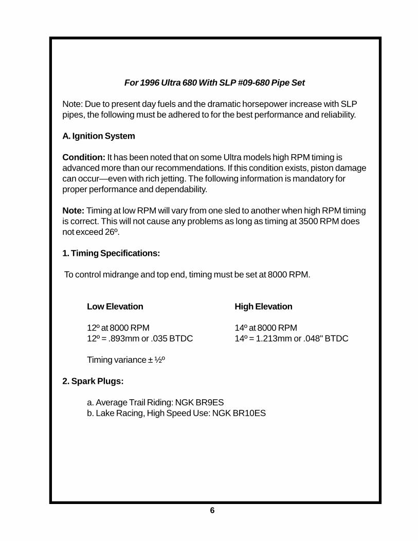
For 1996 Ultra 680 With SLP #09-680 Pipe Set
Note: Due to present day fuels and the dramatic horsepower increase with SLPpipes, the following must be adhered to for the best performance and reliability.
A. Ignition System
Condition: It has been noted that on some Ultra models high RPM timing isadvanced more than our recommendations. If this condition exists, piston damagecan occur—even with rich jetting. The following information is mandatory forproper performance and dependability.
Note: Timing at low RPM will vary from one sled to another when high RPM timingis correct. This will not cause any problems as long as timing at 3500 RPM doesnot exceed 26º.
1. Timing Specifications:
To control midrange and top end, timing must be set at 8000 RPM.
Low Elevation High Elevation
12º at 8000 RPM 14º at 8000 RPM12º = .893mm or .035 BTDC 14º = 1.213mm or .048" BTDC
Timing variance ± ½º
2. Spark Plugs:
a. Average Trail Riding: NGK BR9ESb. Lake Racing, High Speed Use: NGK BR10ES
6

B. Fuel System Requirements
1. Fuel Shut-Off Valve: It has been noted that this valve requires special attentionwhen moving lever to ensure that it is fully open. It has also been noted that the fuelvalve can vibrate or accidently be moved from its open position and restrict fuel flow.Fuel lines or tank vent line, if pinched or kinked, can also reduce fuel flow. Fuel flowrestriction can cause piston damage or failure.
2. Fuel Octane Requirements:
a. Minimum 92 octaneb. RMK Model: If used under 6,000 ft. altitude, use race fuel (100 octane or better.)
3. Oxygenated Fuels: Fuels containing clean air additives, MTBE, Ethanol, Metha-nol, or similar materials—these fuels require additional jet size and are more prone todetonation, especially on long runs at one throttle position.
— Increase main jet by two sizes if using these fuels —
C. Cylinder Head Modification:
Note: Higher-than-factory-recommended compression will reduce perfor-mance and reliability.
1. Low Altitude (0 ft. to 6,000 ft.):
a. SP and SKS models, DO NOT mill heads for higher compression. Evenminimal milling will require use of much higher fuel octane and/or richer fuel mixture.For pump fuel, stock heads are best.
b. RMK model, DO NOT mill heads. Minimum of 100 octane race gas isnecessary for under 6,000 ft. altitude for stock heads.
2. High Altitude (6,000 ft. and higher):
a. SP and SKS models may use RMK heads for high altitude with 92 octanefuel. Machining of SKS and SP heads to duplicate the RMK heads for high altitudeuse is OK, but do not mill more than .015" from head surface. For more performanceand reliability, use SLP Power Dome™ Heads.
7

Illustrations
Illustration 1
Illustration 1A
Rear of Sled
Voltage RegulatorDo Not Disconnect
Yellow WireYellow
Yellow(Center)
Disconnect Black(Toward Front
of sled)Disconnect
Yellow/White
Disconnect Probe
Red/White
8

Illustrations
Line C
Illustration 2
Illustration 3
= 1 7/16”
9

Illustrations
Illustration 4
Illustration 5
10

Illustrations
Illustration 6 Illustration 7
Seal all open areas betweensilencer and belly pan plate.
Illustration 8
SILI
CONE
11

Place heat shield on left side shock tower as shown in illustration.Using heat shield as a pattern, drill two 3/16” holes in shock towerand fasten in place with provided rivets and backing washers.
For 1997 Ultra SP Only
Illustrations
12
6”
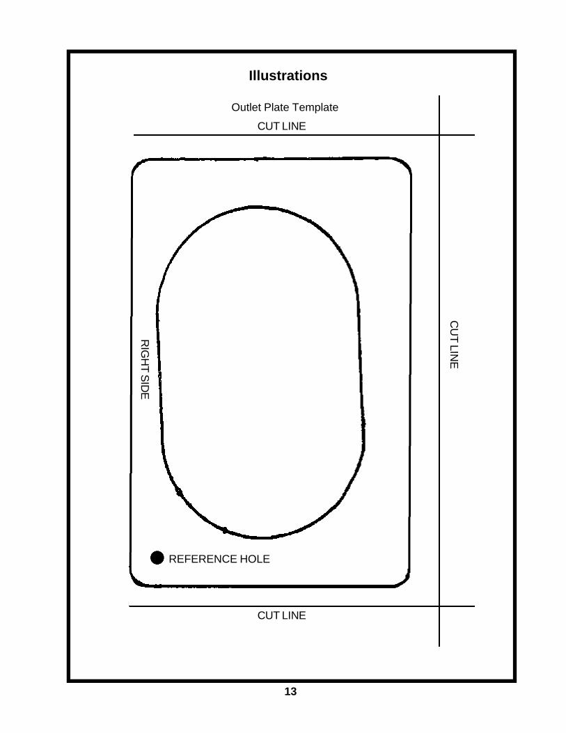
Illustrations
Outlet Plate TemplateCUT LINE
CUT LINE
CU
T LINE
REFERENCE HOLE
RIG
HT SID
E
13