SLOTTED SPRING PINS - Electronic Fasteners - Compliance · PDF file2 SPIROL® Slotted...
8
ISO 8752 ASME B18.8.2 ASME B18.8.4M SLOTTED SPRING PINS
Transcript of SLOTTED SPRING PINS - Electronic Fasteners - Compliance · PDF file2 SPIROL® Slotted...

1
ISO 8752ASME B18.8.2
ASME B18.8.4M
SLOTTED SPRING PINS

2
SPIROL® Slotted spring pins manufactured toISO 8752 (EN 28752), ASME 18.8.4M Type B (Metric),
and ASME B18.8.2 (Inch) are available from stock.
SLOTTED SPRING PINS
MATERIALSCarbon steel: AISI 1070 - 1080
Equivalents: DIN 177222 WkNr 1.1248 CK75 & WkNr 1.1231 CK67BS 1449 67CS & 70CS
Martensitic Stainless Steel: AISI 420Equivalents: DIN 17441 WkNr 1.4021
BS 1449-2 420S45
Austenitic Stainless Steels: AISI 302/304Equivalents: EN 10088 / DIN 17224 WkNr 1.4300 & WkNr 1.4301
BS 1449-2 304S31
• DIN 1481 is interchangeable with ISO 8752 (EN 28752) except fora variation in length tolerance.
• The ASME 18.8.2 range meets the requirement of NASM10971 (formerly MIL-P-1091), NASM 16562 (formerly 16562),
NAS 561, SAE J496, and SAE AS7207 (Superseded AMS 7207and MS 17140-17190).
• ISO 13337 (DIN 7346), lightweight Slotted Pins, are available made-to-order for volume applications.
ISO 9002 and QS-9000 Certificationsare your guarantee for consistent quality.
PART DESCRIPTION
SLTP 4 X 10 BK ISO 8752
StandardFinish
MaterialLength
DiameterPin Type (Slotted)
Beryllium Copper: UNS C17200Equivalents: DIN 17666 WkNr 2.1248
ISO CuBe2Pb
� Contract Review / Quality Planning. A formal procedureexists for the specification and acceptance of new orders bysales, manufacturing and quality.
� Document / Drawing Control. All drawings, standards andspecifications are controlled through engineering.
� SQA Approval of Suppliers and Subcontractors ismaintained by supplier system audits and monitoring ofsupplier quality performance.
� System Audits are carried out regularly by independentauditors with written reports submitted for management action.
� Calibration and Gauge Control. All gauges are calibratedon a regular basis, traceable back to national standards. Thecontrol records are computerized.
� All parts are traceable through each manufacturing processand heat treatment back to the original raw material testcertificate. Each lot has a unique identification number on thepackaging which should be retained by the customer andquoted in the event of any inquiry.
� Manufacturing Controls. There is clear identification of joband quality status with controlled routings. Capability studiesare used to verify machine and process capability; statisticalprocess control is used for all processes, using variable andattribute data; and there are final audit checks of completedparts and stock.
� Non-Conforming Parts. These are segregated with a "hold"label and quarantined pending a decision on disposal. Anautomated corrective action system ensures managementcontrol for quick and accurate responses to customer inquiries.
3
THE CHOICE – ASME OR ISO
SPIROL produces Slotted Pins to both the American National Standard, ASME B18.8.4M and the InternationalStandard, ISO 8752 (EN 28752). It is our recommendation that you consider ASME pins for all new applications andfor your current applications if you are experiencing insertion problems or performance failures. Our recommendationis based on these important advantages of ASME pins:
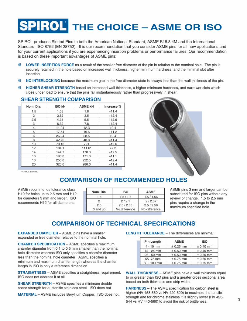
� LOWER INSERTION FORCE as a result of the smaller free diameter of the pin in relation to the nominal hole. The pin issecurely retained in the hole based on increased wall thickness, higher minimum hardness, and the minimal slot afterinsertion.
� NO INTERLOCKING because the maximum gap in the free diameter state is always less than the wall thickness of the pin.
� HIGHER SHEAR STRENGTH based on increased wall thickness, a higher minimum hardness, and narrower slots whichclose under load to ensure that the pins fail instantaneously rather than progressively in shear.
COMPARISON OF TECHNICAL SPECIFICATIONS
COMPARISON OF RECOMMENDED HOLES
ASME pins 3 mm and larger can besubstituted for ISO pins without anyreview or change. 1.5 to 2.5 mmpins require a change in themaximum specified hole.
ASME recommends tolerance classH10 for holes up to 2.5 mm and H12for diameters 3 mm and larger. ISOrecommends H12 for all diameters.
Nom. Dia. ISO ASME
1.5 1.5 / 1.6 1.5 / 1.562 2 / 2.1 2 / 2.07
2.5 2.5 / 2.65 2.5 / 2.583 and up No difference No difference
EXPANDED DIAMETER – ASME pins have a smallerexpanded or free diameter relative to the nominal hole.
CHAMFER SPECIFICATION – ASME specifies a maximumchamfer diameter from 0.1 to 0.5 mm smaller than the nominalhole diameter whereas ISO only specifies a chamfer diameterless than the nominal hole diameter. ASME specifies aminimum and maximum chamfer length whereas the chamferlength in ISO is only a reference dimension.
STRAIGHTNESS – ASME specifies a straightness requirement.ISO does not address it at all.
SHEAR STRENGTH – ASME specifies a minimum doubleshear strength for austenitic stainless steel. ISO does not.
MATERIAL – ASME includes Beryllium Copper. ISO does not.
LENGTH TOLERANCE – The differences are minimal:
WALL THICKNESS – ASME pins have a wall thickness equalto or greater than ISO pins and a greater cross sectional areabased on both thickness and strip width.
HARDNESS – The ASME specification for carbon steel ishigher (HV 458-560 vs HV 420-520) to maximize the tensilestrength and for chrome stainless it is slightly lower (HV 423-544 vs HV 440-560) to avoid the risk of brittleness.
Nom. Dia. ISO kN ASME kN Increase %
1.5 1.58 1.8 +11.42 2.82 3.5 +12.4
2.5 4.38 5.5 +12.63 6.32 7.8 +12.44 11.24 12.3 +9.45 17.54 19.6 +11.26 26.04 28.5 +9.48 42.76 48.8 +11.410 70.16 791 +12.612 104.1 111.6* +7.214 144.7 170.0 +17.516 190.0 171.0 +11.118 250.0 222.5 +12.420 320.0 280.6 +11.4
SHEAR STRENGTH COMPARISON
* SPIROL standard.
Pin Length ASME ISO
4 - 10 mm ± 0.25 mm ± 0.40 mm12 - 24 mm ± 0.50 mm ± 0.40 mm26 - 50 mm ± 0.50 mm ± 0.50 mm55 -75 mm ± 0.75 mm ± 0.60 mm
80 - 100 mm ± 0.75 mm ± 0.75 mm

4
STANDARD LENGTHS AND WEIGHTS (Kg PER 1,000 PCS.)
2.5
0.1180.1420.1890.2360.2830.3300.3770.4240.4710.5190.5650.6130.6600.7070.7540.8250.9421.06
3
0.2040.2720.3400.4070.4750.5430.6110.6790.7460.8140.8820.9501.021.091.191.361.531.70
4
0.4780.5970.7160.8360.9551.071.191.311.431.551.671.791.912.092.392.682.983.283.58
Diameter2
0.0610.0770.0920.1220.1530.1840.2140.2440.2750.3050.3360.3670.3970.4270.4580.4890.5340.610
1.50.0340.0430.0510.0680.0850.1030.1200.1370.1540.1710.1890.2060.2230.240
5
0.9421.131.321.511.701.882.072.262.452.642.833.023.313.774.244.715.185.65
6
1.661.942.212.492.773.043.323.603.874.154.434.845.546.236.927.618.308.999.6910.4
8
3.584.034.484.925.375.826.266.717.167.838.9510.111.212.313.414.515.716.818.019.020.121.322.4
10
7.388.128.869.5910.311.111.812.914.816.618.420.322.124.025.827.729.531.433.235.036.9
12
13.314.415.616.717.819.422.225.027.830.533.336.138.941.744.447.250.052.855.5
Length456810121416182022242628303235404550556065707580859095
100
PIN MATERIALS AND HARDNESS PIN FINISHES
1.52.02.53.03.54.04.55.06.08.0
10.012.014.016.018.020.0
1.602.102.603.103.624.124.625.126.128.1510.1512.1814.1816.1818.1820.21
1.582.824.386.329.09
11.2415.3617.5426.0442.7670.16104.1
144.7 3
171.0 3
222.5 3
280.6 3
NominalPin
Diameter
Pin Diameter
DMax.2Min.1
Chamfer Length
CWall Thickness
SRecommended
Hole SizeDouble Shear StrengthCarbon & Chrome S.S.
Nominal Nominal Min. Max.
B Carbon Steel HV 420-520 K Plain*C Chrome Stainless Steel HV 440-560 P PassivatedD Nickel Stainless Steel Work Hardened T Zinc Plated
1.52
2.53
3.54
4.5*568
101214*1618*20
1.82.42.93.54.04.65.15.66.78.810.812.814.816.818.920.9
1.72.32.83.33.84.44.95.46.48.5
10.512.514.516.518.520.5
0.250.350.400.500.600.650.800.901.202.002.002.002.002.002.003.00
0.30.40.50.60.750.81.01.01.21.52.02.53.03.03.54.0
SPECIFICATIONS in mm
LENGTH
D
SB
D1
D2
D3
C
45˚45˚CHAMFER BOTH ENDS,CONTOUR OF CHAMFER OPTIONAL
1 Minimum diameter is the average of D1, D2, and D3. 2 Maximum measured with go-ring gauge. 3 Carbon Steel only.
ISO 8752EN 28752
20
61.268.976.584.291.899.5
107.1114.8122.4130.1137.7145.4153.0
18*
49.055.161.367.473.579.685.891.998.0104.1110.3116.4122.5
16
32.236.741.345.950.555.159.764.368.973.578.182.787.391.9
14*
23.4
27.331.235.139.042.946.850.154.658.562.466.370.274.177.9
4.5*
0.7930.9521.111.271.431.591.751.902.062.222.382.542.863.173.573.964.364.76
3.5
0.3940.4930.5910.6890.7880.8860.9851.081.181.281.381.481.581.721.972.222.46
B IS LESS THAN NOMINAL PIN DIAMETER
Minimum kN
* Plain carbon steel pins have a protective oil finish.
Nominal Pin Length Length Tolerance
4 to 10 mm ± 0.25 mm12 to 50 mm ± 0.50 mm55 to 100 mm ± 0.75 mm
4 to 10 mm + 0.5 mm12 to 50 mm + 1.0 mm55 to 100 mm + 1.5 mm
Length Tolerance — DIN 1481 (Ref.)
Length Tolerance — ISO 8752
* Not generally a stocked diameter.

5
PIN MATERIALS AND HARDNESS PIN FINISHESB Carbon Steel HV 458-560 K Plain*C Chrome Stainless Steel HV 423-544 P PassivatedD Nickel Stainless Steel Work Hardened T Zinc PlatedI Beryllium Copper HV 354-412 R Phosphated, OiledLENGTH
D
SB
D1
D2
D3
C
45˚45˚CHAMFER BOTH ENDS,CONTOUR OF CHAMFER OPTIONAL
ASME 18.8.4MTYPE B
STANDARD METRIC SIZES AND WEIGHTS (Kg PER 1,000 PCS.)
2.5
0.1420.1890.2360.2830.3300.3770.4240.4710.5190.5650.6130.6600.7070.7540.8250.9421.06
3
0.2040.2720.3400.4070.4750.5430.6110.6790.7460.8140.8820.9501.021.091.191.361.531.70
4
0.4780.5970.7160.8360.9551.071.191.311.431.551.671.791.912.092.392.682.983.283.58
Diameter2
0.0610.0770.0920.1220.1530.1840.2140.2440.2750.3050.3360.3670.3970.4270.4580.4890.5340.610
1.50.0340.0430.0510.0680.0850.1030.1200.1370.1540.1710.1890.2060.2230.240
5
0.9421.131.321.511.701.882.072.262.452.643.833.023.313.774.244.715.185.65
6
1.661.942.212.492.773.043.323.603.874.154.434.845.546.236.927.618.308.999.6910.4
8
3.584.034.484.925.375.826.266.717.167.838.9510.111.212.313.414.515.716.818.019.020.121.322.4
10
7.388.128.869.5910.311.111.812.914.816.618.420.322.124.025.827.729.531.433.235.036.9
12
13.314.415.616.717.819.422.225.027.830.533.336.138.941.744.447.250.052.855.5
Length4568
10121416182022242628303235404550556065707580859095100
Min.1.582.102.623.144.165.176.188.22
10.2512.2814.3016.3218.3520.40
Max.1.41.92.42.93.94.85.87.89.7
11.713.715.617.619.5
0.150.20.20.20.30.30.40.40.50.60.81.01.21.4
0.70.80.91.01.21.41.62.02.42.82.83.03.23.4
0.350.450.550.650.81.01.21.62.02.53.03.03.54.0
1.52.02.53.04.05.06.08.0
10.012.014.016.018.020.0
1.562.072.583.104.125.126.128.15
10.1512.1814.1816.1818.1820.21
SPECIFICATIONS in mm
Min.1 Max.2 Max.
WallThickness
RecommendedHole Size
Min. Max.
Double Shear StrengthChamfer LengthChamferDiameter
Pin Diameter
1.52
2.5345681012
14†*16†18†*20†
1 Minimum diameter is the average of D1, D2, and D3. 2 Maximum measured with go-ring gauge. 3 SPIROL standard. 4 Carbon Steel only.
14†*
24.2
28.332.336.440.444.448.552.556.660.664.668.772.776.880.8
16†
36.141.346.451.656.861.967.172.277.482.687.792.998.0
103.2
18†*
49.455.561.767.974.080.286.492.698.7
104.9111.1117.2123.4
20†
62.470.278.085.793.5101.3109.1116.9124.7132.5140.3148.1155.9
NominalPin
Diameter
Nominal1.02.03.24.57.2
11.416.628.446.160.7
————
1.12.23.54.97.7
12.317.830.549.465.0
————
NickelS.S.
BerylliumCopper
Carbon &Chrome S.S.
Minimum kN
D B C S
1.83.55.57.8
12.319.628.548.879.1
111.6 3
170.0 4
190.0 4
250.0 4
320.0 4
* Plain carbon steel pins have a protective oil finish.
† In conformance with but not part of ASME 18.18.4M.* Not generally a stocked diameter.
1.662.192.723.254.305.336.368.45
10.5112.5514.6016.6518.7120.80
Nominal Pin Length Length Tolerance
Up to 24 mm, incl. ±0.40 mmOver 24 to 50 mm ±0.50 mmOver 50 to 75 mm ±0.60 mmOver 75 mm ±0.75 mm

6
STANDARD SIZES AND WEIGHTS (Kg PER 1,000 PCS.)
PIN MATERIALS AND HARDNESS PIN FINISHESB Carbon Steel HV 458-560 K Plain*C Chrome Stainless Steel HV 423-544 P PassivatedD Nickel Stainless Steel Work Hardened T Zinc PlatedI Beryllium Copper HV 354-412 R Phosphated, Oiled
SPECIFICATIONS in inches
LENGTH
D
SB
D1
D2
D3
C
45˚45˚CHAMFER BOTH ENDS,CONTOUR OF CHAMFER OPTIONAL
Pin Diameter
1/16 .0625/64 .0783/32 .0941/8 .1255/32 .1563/16 .1877/32 .2191/4 .2505/16 .3123/8 .3757/16 .4371/2 .5005/8 3 .6253/4 3 .750
Double Shear StrengthWallThickness
.062
.078
.094
.125
.156
.187
.219
.250
.312
.375
.437
.500
.625
.750
.065
.081
.097
.129
.160
.192
.224
.256
.318
.382
.445
.510
.637
.764
ChamferLength
ChamferDiameter
.066
.083
.099
.131
.162
.194
.226
.258
.321
.385
.448
.513
.640
.768
.069
.086
.103
.135
.167
.199
.232
.264
.330
.395
.459
.524
.653
.784
.059
.075
.091
.122
.151
.182
.214
.245
.306
.368
.430
.485
.608
.730
.007
.008
.008
.008
.010
.011
.011
.012
.014
.016
.017
.025
.030
.045
.028
.032
.038
.044
.048
.055
.065
.065
.080
.095
.095
.110
.125
.150
RecommendedHole Size
Carbon &Chrome S.S. Nickel S.S.
.012
.018
.022
.028
.032
.040
.048
.048
.062
.077
.077
.094
.118
.145
NominalPin
Diameter
430800
115018752750415058507050
108001630019800271004250062500
Min. Max.Min.Min. 1 Max. 2 Max. Max.250460670
1090160024253400410063009500
1150015800 — —
1.102.052.984.857.12
10.7915.1218.2428.0242.2551.1670.28 — —
Nominal Diameter1/16.049.066.082.098.114.130.146.162.179.195.211.227.243.259
5/64.070.095.121.145.171.196.221.246.272.296.322.347.372.397.447.499.549.600
3/32.106.143.179.215.251.287.323.359.395.431.467.507.540.576.648.720.792.865
1/8
.258
.323
.388
.452
.517
.581
.646
.711
.775
.840
.904
.9691.0341.1631.2921.4211.5511.6821.8121.9412.071
5/32
.644
.735
.827
.9181.0091.1001.1911.2831.3731.4631.6451.8282.0102.1932.3752.5572.7402.9223.2873.653
3/16
1.091.241.371.511.641.791.932.062.202.462.743.003.283.543.814.084.344.875.41
7/32
1.511.691.882.072.262.452.642.833.023.403.784.164.544.925.305.686.066.827.588.339.08
5/16
4.434.795.165.535.906.637.268.118.629.599.9811.0611.3413.1514.5115.8817.2418.6019.9621.7723.13
1/2
18.13
21.77
25.40
29.0332.6636.7440.3744.0045.3649.9054.4358.97
7/16
10.93
13.66
16.39
19.13
21.8624.5927.3230.0532.7935.5238.2540.9243.93
3/8
6.46
7.54
8.62
10.69
13.15
15.42
17.2419.5021.7720.0426.3128.1230.3932.6634.93
1/4
1.832.062.292.522.752.983.213.443.674.124.585.045.495.956.406.867.328.249.15
10.0610.9711.8812.80
Length
3/161/45/163/87/161/29/165/8
11/163/4
13/167/8
15/161
1-1/81-1/41-3/81-1/21-5/81-3/41-7/8
22-1/42-1/22-3/4
33-1/43-1/23-3/4
4
1 Minimum diameter is average of D1, D2 and D3. 2 Maximum diameter measured with go-ring gauge. 3 SPIROL standard, Carbon Steel only.
ASME 18.8.2
5/8*
115.5129.9144.4158.8173.3187.7202.1216.6231.0
3/4*
154.2173.5192.8212.0231.3250.6269.9289.1308.4
Minimum Lbs. and kN2.003.565.128.34
12.2318.4626.0231.3648.0472.5088.08
120.55189.06278.02
D B C SNom.
* Plain carbon steel pins have a protective oil finish.
270500710
117017252600365044006750
102001230017000 — —
1.202.223.165.207.67
11.5716.2419.5730.0345.3754.7275.62 — —
BerylliumCopper
* SPIROL standards.
Nominal LengthPin Length Tolerance
Up to 1”, incl. ±0.015Over 1” to 2”, incl. ±0.020Over 2” to 3”, incl. ±0.025Over 3” to 4”, incl. ±0.030Over 4” ±0.035

7
TECHNICAL INFORMATION
Typical pin shear test fixture
SHEAR STRENGTHThe shear test procedure is set forth in ISO 8752, SAE J496,and NASM 10971, which are identical in substance.
Load Shear block
Hardenedbushings
Pin
Spacer
Spacer and guidesfor shear block
Hardened supportblock
Fixture
Load Hardened shearblock
RECOMMENDED PIN/SHAFT RATIOThe recommended maximum ratio is 1 to 3; that is the pindiameter should never exceed 33.3% of the shaft diameter. Ifthis limit is exceeded, the remaining material in the shaft isinadequate and the shaft will fail before the pin.
DOUBLE PINNINGIn situations requiring exceptionally high shear strength, it ispossible to use pins in combination by driving an inner pin intoan already inserted outer pin. The gaps should be 180°opposed. The recommended hole needs to be increased. It issuggested you consult Spirol Application Specialists in thesesituations.
WHICH STAINLESS?Martensitic chrome stainless is hardened and has strengthcomparable to carbon steel and satisfactory corrosionresistance in most cases. Austenitic nickel stainless steel hasbetter corrosion resistance in some environments but since it isnot hardened, it has lower strength and requires more care inthe insertion process.
HOLE PREPARATIONHoles can be drilled, punched or cast with no need foradditional reaming or sizing. Care should be taken to avoidundersize holes to eliminate potential pin damage duringinsertion. The following points are suggested for yourconsideration:
� Break or debur the edges, particularly in case of hardenedholes.
� Countersinking is not recommended if it increases theclearance at the shear plane.
� In case of cast or sintered metal holes, provide a lead-inradius.
� Whenever possible, punched holes should be punched inthe same direction as the direction of pin insertion.
� Eliminate hole misalignment problems by drilling holestogether.
� In case of hardened collars or similar components, flattenthe component at the entry of the hole to avoid two-pointcontact as the pin starts into the hole.
Shear values specified will only be obtained under theconditions noted in the referenced standards. Of special note:
� The clearance at the shear plane cannot exceed 0.15 mmor .005”.
� The hole has to be the nominal pin diameter (tolerance H6)with a hardness of not less than HV 700.
� The pin must be installed with the slot up.� The shear planes have to be at least one pin diameter from
each end, and at least two diameters apart.
STRAIGHTNESS SPECIFICATION(ASME PINS ONLY)The straightness over the length of the pins shall be such thatthe pin will pass freely through a ring gauge of the length anddiameter as specified below.
Up to 24 mmUp to 1”24 mm – 50 mm1” – 2”Over 50 mmOver 2”
25 ± 0.151” ± .005"50 ± 0.152” ± .005"75 ± 0.153” ± .005"
0.20 – 0.22.007"
0.40 – 0.43.010"
0.60 - 0.64.013"
Pin Length Gauge Length Max. Pin Dia. Plus
STRAIGHTNESS GAUGE SPECIFICATIONS
Nom. PinDiameter
0.200.250.250.500.500.700.700.90
1.502.403.508.00
10.4018.0024.0040.00
ExpandedDiameter
22.534568
10
2.32.83.34.45.46.48.5
10.5
ChamferLength
WallThickness
SPECIALSOTHER COMMON SPECIALS:
� Special Lengths
� Special Materials
� Special Tolerances
� Special Finishes
� Special Packaging
ISO 13337 (DIN 7343) SPECIFICATIONSDouble Shear StrengthCarbon & Chrome S.S.
Min. kM
2.42.93.54.65.66.78.8
10.8
0.400.450.450.700.700.900.901.10
0.200.250.300.500.500.750.751.00
Min. Max.Min. Max. Nominal

8
Applications
Typical applications use springpins as...
� Fasteners to secure handlesand gears to shafts
� Retaining pins� Axle shafts� Stop pins� Hinge and pivot applications� Cross bars� Tube reinforcing pins� Locator pins
SPIROL® slotted spring pinsare used in many industries.
� Agriculture� Automotive� Construction� Appliances� Electronics� Furniture� Mining� Plastics� Railways� Aerospace
FREE APPLICATION ANDINSERTION CONSULTATION
© 2004 Spirol International Corporation 15M 04/04 Printed in U.S.A. e-mail: [email protected]
Canada
Mexico
Europe
U.S.A. Spirol International Corporation30 Rock AvenueDanielson, Connecticut 06239Tel.] 860.774.8571 Fax] 860.774.2048www.spirol.com
Spirol West645 East Harrison Street, Suite 100Corona, California 92879-1347Tel.] 909.273.5900 or 800.776.9528Fax] 909.273.5907www.spirolwest.com
Spirol International Corporation Shim Division321 Remington RoadStow, Ohio 44224Tel.] 330.920.3655 Fax] 330.920.3659www.spirol.com
Ascutney Metal Products2637 US Route 5 NorthWindsor, Vermont 05089Tel.] 802.674.6721 Fax] 802.674.6121www.ascutneymp.com
Spirol Distribution30 Rock AvenueDanielson, Connecticut 06239Tel.] 800.321.4679 Fax] 860.774.0487www.spirol.com(For Distributor Customers)
Spirol Industries, Ltd.3103 St. Etienne BoulevardWindsor, OntarioCanada N8W 5B1Tel.] 519.974.3334 Fax] 519.974.6550www.spirolcanada.com
Spirol México, S.A. de C.V.Carretera a Laredo KM 16.5 Interior ECol. Moises SaenzApodaca, N.L. México C.P. 66605Tel.] (81) 8385 4390 Fax] (81) 8385 4391www.spirol.com.mx
Spirol Industries, Ltd.Princewood RoadCorby, NorthantsEngland NN17 4ETTel.] 44 (0) 1536 444800Fax] 44 (0) 1536 203415(For Distributor Customers)Tel.] 44 (0) 8003 890034www.spirol.co.uk
Spirol SASRue Henri Roi TanguyZ.A. Les Naux51450 Bétheny FranceTel.] 33 (0)3 26 36 31 42Fax] 33 (0)3 26 09 19 76www.spirol.com
I N T E R N A T I O N A L
ISO9001:2000 Certificate No. 11168
QS-9000 Certificate No. 5981 QS-9000:1998FM 64050
ISO 9002 Certificate No. Q 09419BS 5750
California England
Connecticut Canada
Chal lenge Us!