SLOPE TEST LOAD MONITORING IN PURPOSE ASSES SAFETY OF …
9
* Ph.D. Marta Pająk, Consulting and Research Institute GEOCONTROL Ltd. Of Road and Bridges, Departments of Geotechnics and Underground Studies. ** Prof. Ph.D. Eng. Anna Sobotka, Department of Geomechanics, Civil Engineering and Geotechnics, Faculty of Mining and Geoengineering, AGH University of Technology and Science. *** Ph.D. Eng. Grzegorz Kacprzak, Department of Geotechnics and Underground Studies, The Institute of Road and Bridges, Warsaw University of Technology. MARTA PAJĄK * , ANNA SOBOTKA ** , GRZEGORZ KACPRZAK *** SLOPE TEST LOAD MONITORING IN PURPOSE ASSES SAFETY OF THE CRANE MOUNTING MONITORING PRÓBNEGO OBCIĄŻENIA SKARPY DLA OCENY BEZPIECZENSTWA ŻURAWIA MONTAŻOWEGO Abstract Presented topic concerns the location on the crown of the high slope settings crane to be mounted on the roof structure construction of the building NOSPR in Katowice. Set AC500 crane mounting on a high slope required to verify the safety of the location, the forecast behavior of the slope during the operation of the crane, and conduct constant monitoring of geodetic displacement of the slope. The aim of the paper is to present the proposed and implemented methodology based on data acquisition geotechnical soil slope using the methods of surveying as well as analysis of integrated measurements for the design and implementation of the safe conduct of works chosen method of installation. Keywords: location of the crane assembly, load test of the slope, geodetic monitoring Streszczenie Przedstawiony temat dotyczy lokalizacji na koronie wysokiej skarpy ustawienia żurawia do montażu kon- strukcji dachowej na budowie budynku NOSPR w Katowicach. Ustawienie żurawia AC500 na skarpie wy- magało sprawdzenia bezpieczeństwa tej lokalizacji, wykonania prognozy zachowania się skarpy podczas pracy żurawia oraz prowadzenia stałego monitoringu geodezyjnego przemieszczeń skarpy. Celem artykułu jest przedstawienie zaproponowanej i wdrożonej metodyki opartej na pozyskiwaniu danych geotechnicz- nych gruntu skarpy przy użyciu metod geodezyjnych oraz analiza zintegrowanych wyników pomiarów do projektu i realizacji bezpiecznego prowadzenia robót wybranej metody montażu. Słowa kluczowe: lokalizacja żurawia, próbne obciążenie skarpy, monitoring geodezyjny TECHNICAL TRANSACTIONS CIVIL ENGINEERING 1-B/2014 CZASOPISMO TECHNICZNE BUDOWNICTWO brought to you by CORE View metadata, citation and similar papers at core.ac.uk provided by Portal Czasopism Naukowych (E-Journals)
Transcript of SLOPE TEST LOAD MONITORING IN PURPOSE ASSES SAFETY OF …
* Ph.D. Marta Pająk, Consulting and Research Institute GEOCONTROL Ltd. Of Road and Bridges, Departments of Geotechnics and Underground Studies.
** Prof. Ph.D. Eng. Anna Sobotka, Department of Geomechanics, Civil Engineering and Geotechnics, Faculty of Mining and Geoengineering, AGH University of Technology and Science.
*** Ph.D. Eng. Grzegorz Kacprzak, Department of Geotechnics and Underground Studies, The Institute of Road and Bridges, Warsaw University of Technology.
MARTA PAJĄK*, ANNA SOBOTKA**, GRZEGORZ KACPRZAK***
SLOPE TEST LOAD MONITORING IN PURPOSE ASSES SAFETY OF THE CRANE MOUNTING
MONITORING PRÓBNEGO OBCIĄŻENIA SKARPY DLA OCENY BEZPIECZENSTWA ŻURAWIA
MONTAŻOWEGO
A b s t r a c t
Presented topic concerns the location on the crown of the high slope settings crane to be mounted on the roof structure construction of the building NOSPR in Katowice. Set AC500 crane mounting on a high slope required to verify the safety of the location, the forecast behavior of the slope during the operation of the crane, and conduct constant monitoring of geodetic displacement of the slope. The aim of the paper is to present the proposed and implemented methodology based on data acquisition geotechnical soil slope using the methods of surveying as well as analysis of integrated measurements for the design and implementation of the safe conduct of works chosen method of installation.
Keywords: location of the crane assembly, load test of the slope, geodetic monitoring
S t r e s z c z e n i e
Przedstawiony temat dotyczy lokalizacji na koronie wysokiej skarpy ustawienia żurawia do montażu kon-strukcji dachowej na budowie budynku NOSPR w Katowicach. Ustawienie żurawia AC500 na skarpie wy-magało sprawdzenia bezpieczeństwa tej lokalizacji, wykonania prognozy zachowania się skarpy podczas pracy żurawia oraz prowadzenia stałego monitoringu geodezyjnego przemieszczeń skarpy. Celem artykułu jest przedstawienie zaproponowanej i wdrożonej metodyki opartej na pozyskiwaniu danych geotechnicz-nych gruntu skarpy przy użyciu metod geodezyjnych oraz analiza zintegrowanych wyników pomiarów do projektu i realizacji bezpiecznego prowadzenia robót wybranej metody montażu.
Słowa kluczowe: lokalizacja żurawia, próbne obciążenie skarpy, monitoring geodezyjny
TECHNICAL TRANSACTIONSCIVIL ENGINEERING
1-B/2014
CZASOPISMO TECHNICZNEBUDOWNICTWO
brought to you by COREView metadata, citation and similar papers at core.ac.uk
provided by Portal Czasopism Naukowych (E-Journals)

256
1. Introduction
The construction of buildings in difficult conditions, eg in densely built areas, it is often only possible through the use of unusual solutions, increasing risks to the site and its surroundings.
Designing a secure method for the execution of works requires the analysis of many factors, prediction of behavior, preliminary tests, simulations and field tests.
The article is a case study evaluation of the crane foundation excavation on a high slope, while construction works on the roof was carried out in winter, monitoring and evaluating displacements using geodetic monitoring.
The aim of this paper is to present a hybrid monitoring system using geodetic and geotechnical work for conducting field trials of static loads to control the execution of the construction process. The prescribed solution assumed the position of the crane location in close proximity to the edge of the escarpment. Geodetic monitoring of the slope with the implementation of the test static load of the slope is a complete and continuous solution and source of information with regard to changes in the geometry of the slope. For the implementation of a hybrid coherent program of research – control requires the cooperation of specialists in geology, geodesy and geotechnology. At the design stage and also at the stage of system implementation, the entire system is a combination of interdisciplinary knowledge and the collaboration engineers from various industries. Set geological and geodetic data must be analyzed and interpreted by a team of geotechnics engineers – the organizational structure led task stems from the need for a continuous flow of feedback and information in order to ensure the safety of the people leading the work on the site as well as the entire infrastructure of the site NOSPR (construction of the new headquarters of the National Polish Radio Symphony Orchestra in Katowice) [1, 2].
The scope of the article includes the results of the calculation and verification of the terrain using the probationary static load.
2. Description of the implementation of the mounting of crane
Erecting the new headquarters of the National Polish Radio Symphony Orchestra was conducted in difficult conditions from an organizational point of view due to the limited surface and complex high-rise construction site conditions. Collision-free positioning of the crane, to provide the necessary range for the installation of the roof was only possible from one side of the building, in an area where there was a deep trench. In the excavation that had already been carried out, construction work a smaller crane was also located. Thus, positioning of the AC500 crane assembly had to take place on a high slope. The question arises as to whether such an arrangement is safe and what action is required to check the security risk of the works, to predict the behavior of the slope, to take action to prevent the appearance of the effects of risk. Figure 1 shows a schematic arrangement of the crane bracket.
Slope excavation was carried out in order to analyze the causes of problems associated with the crane under load, the main issue being the stability of slope, which is one of the basic problems of geotechnics. Escarpments or slopes are classified as stable, if mass movements

257
such as landslides and talus have not been occurring. A measure of the stability of a slope is the ratio of forces or moments of forces seeking to balance the forces and moments of forces seeking to landslide. Risk of loss of stability of the slope or hillside, is often due to a distortion of the conditions of equilibrium. The basic reason is subsidence of the earth mass that occurs as a result of exceeding the shear strength of the soil along any (but continuous) surface, called the slip surface. One of the characteristics of subsidence of slope is that the fundamental forces that cause them are: the gravitational forces from the weight of the soil and the possible building and hydrodynamic forces caused by the flow of water through the soil.
Causes of loss of stability of the slope or the slope or the creation of landslides may be natural, independent, as well as his due interference. The most common are:a) collapsed layers of land or direction of crack rocks in the direction of inclination of the
slope or the slope of the natural or artificial (trench);b) washes out or undermining of the slope or the slope;c) additional load on the slope or the slope or land on them by new structures and ma-
terial compositions or operating machinery;d) water filling gaps or cracks over the escarpment or edge;e) a sudden decrease in the level of surface water (eg dams and embankments land);f) the water pressure from the bottom to the upper layers of permeable little effect of redu-
cing the resistance to shear forces;g) due to soak the soil rain or snow thaw, which causes swelling of the soil, thereby reducing
the shear strength of the soil;h) Weathering and loosening rocks and soil, thus destroying their structure;i) The existence polished slip surface areas of old landslides (eg, clays and iłołupkach);j) shocks caused by such an avalanche, explosions, earthquakes, traffic;k) Scouring, ie. leaching of the soil mass finer grains or particles by infiltrating water causes
the formation of voids, and then moves masses of rock or soil;l) freezing and thawing of soil causing a change in its structure and shear strength;m) Displacement of the soil; n) Poor design of the overburden, the inclination of the slope excavation or embankment.
Of course, the possibility of simultaneous occurrence of more than one cause had to be taken into account. The NOSPR construction location also required the analysis of slope stability and road traffic – point j); aspects of design and construction – point n) weather conditions – point l) and provided for mounting the crane on a slope – point c).
Fig. 1. The crane location scheme

258
3. Methodology of problem solving
The next step in the assessment of securing the slope crane foundation destined for the execution of the works included the installation of the roof structure: a) Local Visions and field work; b) Analysis of archival geological studies for the present escarpment; c) The analysis of the assumptions Crane Assembly of the Organization of the Project, the
location of the foundation provided services on the slope; d) The concept of positioning the crane on the basis of the analysis of ground conditions in
the substrate structure and knowledge about the problems with the stability of slope; e) Selection of models and calculation methods; f) The interpretation of calculations; g) Conduct field trial of the static load and geodetic monitoring; h) The analysis of the results from field studies; i) The location of the crane on a slope; j) Monitoring of surveying during the performance of the crane assembly, along with a con-
tinuous current safety analysis work. Calculations and analysis of the task were performed to assess the stability of the
slope at the north wall of the main building erected on the NOSPR site. While conducting computational methods for the analysis of slope stability it was possible to reduce the computational analysis by only using the Fellenius’s method. The use of other methods should be at least mirrored, to eliminate the imposition of a variety of errors and establish full convergence of the calculation. As part of this analysis calculations, a total of three methods were used, namely the Fellenius’s method along with two other complementary methods: Bishop and Spencer [4]. The main factors included in the analysis were: – Planned additional burden on the weight of the slope hydraulic crane DEMAG AC500; – Weather conditions, including the freezing and thawing of the ground, causing a change
in the structure and strength. – Three chosen calculations were made for the depth of the crane foundation: – Assuming that the foundation of the crane will be made on the surface of the slope, main-
taining its existing amount (the first phase); – Assuming deepen the foundation level of 2.0 [m], but only a foot from the side of the
trench (the second phase) – the implementation of this version would include the execu-tion pits with a depth of 2.0 [m] on the slope side of the trench;
– Assuming a reduction in the level of the whole foundation of the crane (the third phase) the implementation of this version would include the execution pits with a depth of 2.0 [m] for all foot crane.On the basis of calculations made and the interpretation of the results of calculation and
situational analysis and also taking the planned foundation for the DEMAG AC500 crane into account – it was found that the assumptions considered showed that the escarpment at the northern wall of the main building fulfilled the computational requirement of stability. At the same time – for verification of safety of slope stability – it was necessary to fulfill the requirements in the field of geotechnical works, contained in the Project Organization Demag AC500 Crane Assembly. Project Organization Assembly guidelines NO 4/ZMPK/2012A ... state that “before the arrival of the crane, the ground floor under the supports of the crane should be tested. (...) Because of the new embankment from the side of the building is

259
recommended to support the axis 1, the prepared foundation of reinforced concrete slabs, execution min. 8 godzinnego ballast load 150 t (...)”.
After laying the ballast in the form of blocks with a total weight of 150 tonnes (Fig. 2) and is made of concrete slabs control measurement readings benchmarks. Schematic layout of measuring benchmarks are shown in Figure 3 In order to allow for the assessment of the impact of the time factor on the size of the displacement of the slope was instructed to withstand the loading ballast for not less than three days. Geodetic control readings were performed in a total time of 96 hours – starting from the pose of full ballast loading. Installation of the DEMAG AC500 hydraulic crane was only possible after no evidence of any instability of the slope was found; proven in the in-situ construction, ie after the ballast load the test substrate.
Fig. 2. A test load of the slope with ballast
Characteristics of geodetic monitoring for analysed task
Monitoring was carried out in order to observe the deformation and ongoing analysis of slope stability at the northern wall of the main building erected on the NOSPR site, in terms of impacts from the foundation of the crane on a slope. The observation was carried out continuously during the period from 07.02.2013 to 18.02.2013. Results of measurements obtained were analyzed using current methods, the purpose of which was to assess the stability of the slope. The present height of the slope is about eight meters. The escarpment was subjected to impacts from the weight of the crane, which was situated at a distance of about 1.5 m from the edge. Conducted monitoring of the slope took a Geomatics analysis for the continuous collection of information. This analysis, in contrast to the classical measure of control, specifying the location and condition of the course evaluation survey at the time, provided an opportunity to assess the dynamics of the phenomena and processes that identify their effect, providing the ability to conduct analysis and modeling potential [1, 2].
Surveying the present slope was carried out to determine the geometrical relationships which are the result of different phenomena. Measurements were taken regularly (every few hours) and also gave an insight into the behavior of the observed slope.
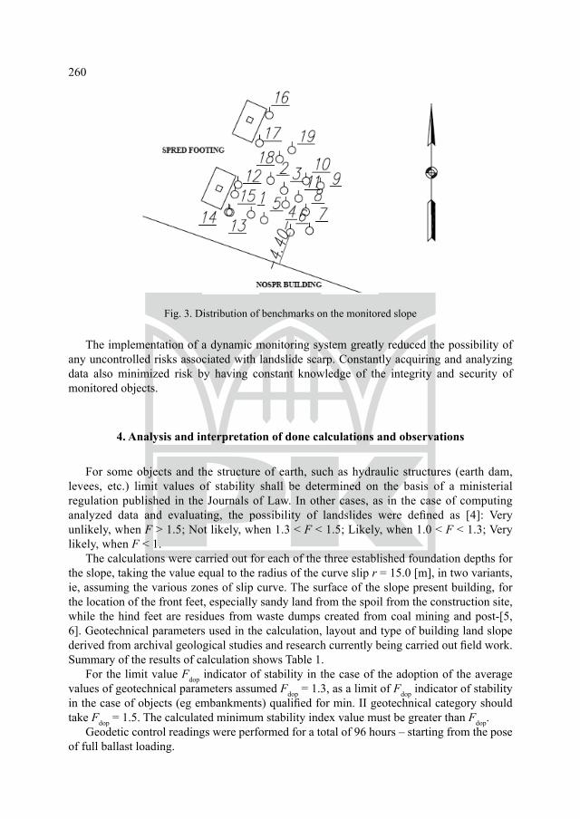
260
Fig. 3. Distribution of benchmarks on the monitored slope
The implementation of a dynamic monitoring system greatly reduced the possibility of any uncontrolled risks associated with landslide scarp. Constantly acquiring and analyzing data also minimized risk by having constant knowledge of the integrity and security of monitored objects.
4. Analysis and interpretation of done calculations and observations
For some objects and the structure of earth, such as hydraulic structures (earth dam, levees, etc.) limit values of stability shall be determined on the basis of a ministerial regulation published in the Journals of Law. In other cases, as in the case of computing analyzed data and evaluating, the possibility of landslides were defined as [4]: Very unlikely, when F > 1.5; Not likely, when 1.3 < F < 1.5; Likely, when 1.0 < F < 1.3; Very likely, when F < 1.
The calculations were carried out for each of the three established foundation depths for the slope, taking the value equal to the radius of the curve slip r = 15.0 [m], in two variants, ie, assuming the various zones of slip curve. The surface of the slope present building, for the location of the front feet, especially sandy land from the spoil from the construction site, while the hind feet are residues from waste dumps created from coal mining and post-[5, 6]. Geotechnical parameters used in the calculation, layout and type of building land slope derived from archival geological studies and research currently being carried out field work. Summary of the results of calculation shows Table 1.
For the limit value Fdop indicator of stability in the case of the adoption of the average values of geotechnical parameters assumed Fdop = 1.3, as a limit of Fdop indicator of stability in the case of objects (eg embankments) qualified for min. II geotechnical category should take Fdop = 1.5. The calculated minimum stability index value must be greater than Fdop.
Geodetic control readings were performed for a total of 96 hours – starting from the pose of full ballast loading.

261T a b l e 1
Results of calculations with values of safety factors for slope stability
Lp.Methodology First Second
Phase first second third first Secondo third1 Bishop’s metod 1.52 1.58 1.85 1.52 1.55 1.582 Fellenius’s metod 1.41 1.48 1.58 1.37 1.45 1.523 Spencer’s metod 1.65 1.63 1.91 1.45 1.53 1.63
Then the precise geodetic measurements included the monitoring of horizontal and vertical displacements of individual benchmarks situated on the crown and the slope of the escarpment in the period from 07.02.2013 to 18.02.2013. Selected results of measurements on the vertical displacements are shown in Table 2.
T a b l e 2
Examples of measurements of vertical displacements
Bench- mark No.
Number and date of measumerent Analysis of displacement’s differrence [ImmI] with load 1500 kN
Measu merent I [24hours]
MeasumerentII [48hours]
Measumerent III [72hours] Δ I–II Δ II–III Δ complete
1. 1.66 1.96 2.00 0.30 0.04 0.34
2. 2.22 3.78 3.24 1.56 0.54 1.02
3. 3.06 4.22 3.72 1.16 0.50 0.66
4. 3.54 4.32 3.00 0.78 1.32 0.54
5. 1.92 2.66 1.36 0.74 1.30 0.60
6. 1.00 2.32 2.92 1.32 0.60 1.92
7. 1.00 3.96 3.92 2.96 0.04 2.92
8. 2.00 4.92 4.54 2.92 0.38 2.54
9. 1.00 3.44 3.56 2.44 0.12 2.56
10. 3.00 5.30 4.68 2.30 0.62 1.68
11. 3.00 5.02 3.16 2.02 1.86 0.16
12. –1.68 –2.30 –4.56 0.62 2.26 2.88
13. –0.32 –0.02 –1.90 0.30 1.88 1.58
14. –10.24 –16.59 –17.46 6.35 0.87 7.22
15. –7.58 –12.47 –14.73 4.89 2.26 7.15

262
On the basis of the results of surveying benchmarks on a slope on the construction and analysis of archival materials, and based on the opinion of the designer POM confirmed the behavior of the slope stability of the test and, therefore, the DEMAG AC500 could be mounted. At the time of installation, the crane, as well as the working time, it was recommended that the slope surface should be covered tight with plastic foil and conduct constant geodetic monitoring in terms of the current movements of the slope.
The results of the monitoring geodetic on current horizontal and vertical displacements of the slope showed a slight displacement. Comparative analysis of the movements showed a stabilization of vertical and horizontal displacements of the first stage of the application of the total load. – The monitoring function of surveying was to enable efficient and safe execution of tasks
on the site and to enable continuous assessment of the task, in terms of behavior of the slope of the load.
– The main objectives have been achieved as part of its monitoring and research were: – Recording displacement parameters along with the reflection of the burden and stress
conditions; – Providing continuous information to estimate displacements of the slope; – Documenting the following phenomena on the crown and the slope of the escarpment; – Allowing the estimation of capacity with the present escarpment; – Verification of the assumptions of the Project Organization Crane Assembly.
5. Conclusions
The design and execution of works, and especially the determination and organization of work working groups seemed to be an unproblematic issue. It turns out, however, that a wide variety of circumstances take place when these conditions are difficult for various reasons (as in the present case), they are often complicated because of the parallel execution of works, even if there is a need to overcome delays, etc. It is very difficult causes a risk of loss of safety. Then careful design, often supported by field studies, numerical simulations, etc., requiring use of the knowledge and skills of specialists in different areas and the additional time and cost to its safety.
Geodetic monitoring with static load tests were used in the case presented, which included: – Design of assembly works; – Continuous assessment of the conservation status of the geometry of the analyzed slope; – Efficient and safe conduct of construction work.
The proposed methodology for project development and construction works depend on the behavior of the soil, combining knowledge of geotechnical and geodetic, which allowed for the safe completion of the planned works, ie the installation of the roof.

263
R e f e r e n c e s
[1] Cavanagh J., Geomatics, New Jersey 1999.[2] James H., Automatic deformation monitoring, The American Surveyor, 2006.[3] Karsznia K., Wykrywanie słabych punktów, Nowoczesne budownictwa inżynieryjne,
nr 7–8, 2008.[4] Karsznia K., Wrona M., Zintegrowane systemu monitoringu geodezyjnego w badaniu
dynamiki konstrukcji inżynierskich obiektów budowlanych, Geodeta, nr 3, 2009.[5] Siemińska-Lewandowska A., Budowa obiektu, a obudowa wykopu – niełatwe Zależno-
ści. Nowoczesne Budownictwo Inżynieryjne, nr 2/2010, 64-71.[6] Pisarczyk S., Gruntoznawstwo inżynierskie, PWN, Warszawa 2001. [7] Wolski B., Monitoring metrologiczny obiektów geotechnicznych, Wydawnictwo Poli-
techniki Krakowskiej, Kraków 2006.[8] Dokumentacja geologiczno-inżynierska dla siedziby NOSRP w rejonie ulic Olimpijskiej
i Roździeńskiego w Katowicach, opracowana we wrześniu 2009 przez Przedsiębiorstwo Geobud z Katowic.
[9] Projekt Organizacji Montażu NR 4/ZMPK/2012A dotyczący montażu konstrukcji sta-lowej dachu nowo budowanego budynku Narodowej Orkiestry Symfonicznej Polskiego Radia w Katowicach, 2014.