![Slope Deflection Method[1]](https://static.fdocuments.us/doc/165x107/5571fe4449795991699b02b5/slope-deflection-method1.jpg)
Slope Deflection Method - Asad Iqbalengrasad.weebly.com/uploads/1/4/2/1/14213514/lecture_6.pdf ·...
97
Slope‐Deflection Method Theory of Structures‐II M Shahid Mehmood Department of Civil Engineering Swedish College of Engineering & Technology, Wah Cantt
-
Upload
trannguyet -
Category
Documents
-
view
246 -
download
2
Transcript of Slope Deflection Method - Asad Iqbalengrasad.weebly.com/uploads/1/4/2/1/14213514/lecture_6.pdf ·...
Slope‐Deflection Method
Theory of Structures‐II
M Shahid Mehmood
Department of Civil Engineering
Swedish College of Engineering & Technology, Wah Cantt
Slope‐Deflection Method
• Previously we have discussed Force/Flexibility methodsof analysis of statically indeterminate structures.
• In force method, the unknown redundant forces aredetermined first by solving the structure’s compatibility
ti th th h t i ti f thequations; then other response characteristics of thestructure are evaluated by equilibrium equations orsuperpositionsuperposition.
• An alternative approach can be used for analyzing is• An alternative approach can be used for analyzing istermed the displacement or stiffness method.
2
Slope‐Deflection Method
• In displacement method, the unknown displacements aredetermined first by solving the structure’s equilibriumequations; then the other response characteristics areevaluated through compatibility considerations andevaluated through compatibility considerations andmember force‐deformation relationships.
• The displacement methods includes Slope‐DeflectionMethod and Moment‐Distribution MethodMethod and Moment Distribution Method.
• The slope‐deflection method was introduced by George• The slope‐deflection method was introduced by GeorgeA. Maney in 1915.
3
Slope‐Deflection Method
• This method takes into account only the bendingdeformations.
• This method gives an understanding of the Matrix‐Stiffness Method, which forms the basis of most
t ft tl d f t t l l icomputer software currently used for structural analysis.
4
Slope‐Deflection Equations
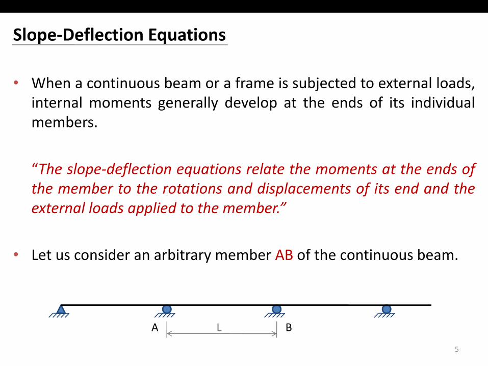
• When a continuous beam or a frame is subjected to external loads,internal moments generally develop at the ends of its individualinternal moments generally develop at the ends of its individualmembers.
“The slope‐deflection equations relate the moments at the ends ofthe member to the rotations and displacements of its end and theexternal loads applied to the member”external loads applied to the member.
• Let us consider an arbitrary member AB of the continuous beam.y
5
A BL
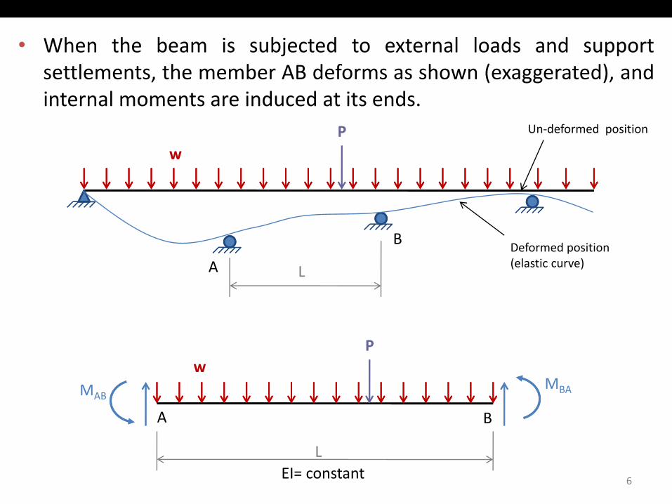
• When the beam is subjected to external loads and supportsettlements the member AB deforms as shown (exaggerated) andsettlements, the member AB deforms as shown (exaggerated), andinternal moments are induced at its ends.
P Un‐deformed position
w
A
B
L
Deformed position(elastic curve)
P
A B
wMAB
MBA
6
LEI= constant
wP
LA B
wMAB
MBA
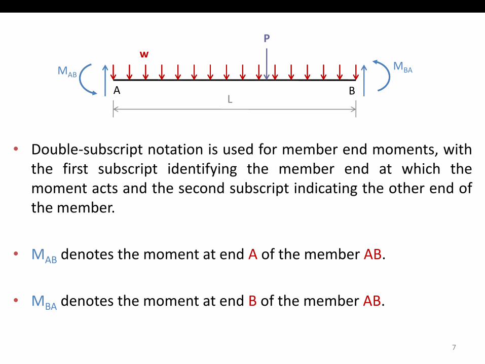
• Double‐subscript notation is used for member end moments, withp ,the first subscript identifying the member end at which themoment acts and the second subscript indicating the other end ofthe memberthe member.
• MAB denotes the moment at end A of the member AB.AB
• MBA denotes the moment at end B of the member AB.
7
w PMAB
MBA
LA BAB
Un‐deformed positionTangent at A
A B
Elastic curve
A’
B’Elastic curve
θA θB
Tangent at B
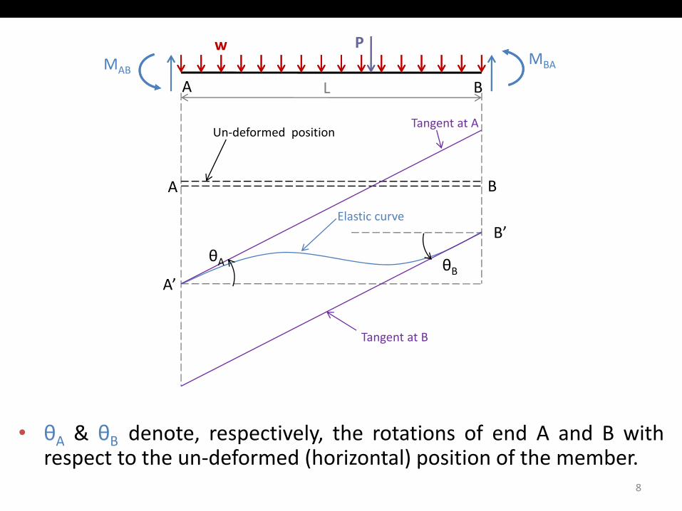
• θA & θB denote, respectively, the rotations of end A and B withθA & θB denote, respectively, the rotations of end A and B withrespect to the un‐deformed (horizontal) position of the member.
8
w PMAB
MBA
LA BAB
Un‐deformed positionTangent at A
A B
Elastic curve
A’
B’Elastic curve
θA θBΔ
Tangent at B
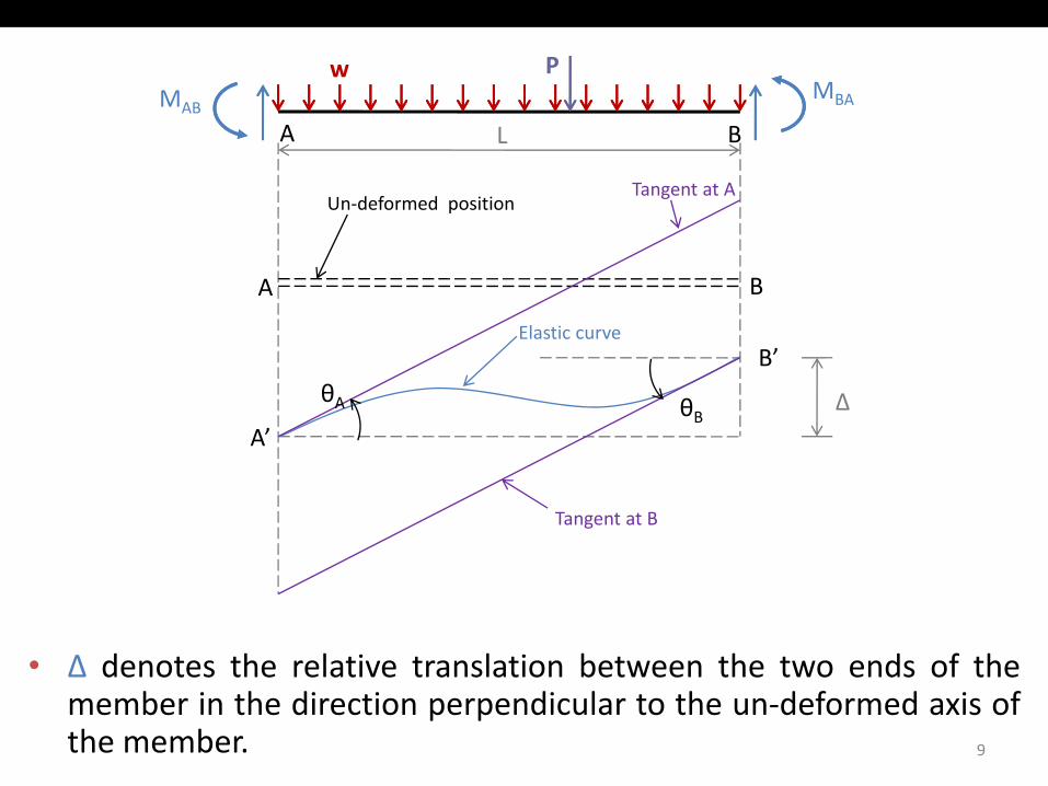
• Δ denotes the relative translation between the two ends of theΔ denotes the relative translation between the two ends of themember in the direction perpendicular to the un‐deformed axis ofthe member. 9
w PMAB
MBA
LA BAB
Un‐deformed positionTangent at A
A B
Elastic curve
A’
B’Elastic curve
θA θBΔ
Ψ
Ψ
Tangent at B
Cord
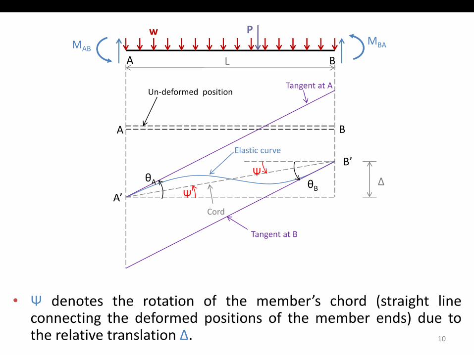
• Ψ denotes the rotation of the member’s chord (straight lineΨ denotes the rotation of the member s chord (straight lineconnecting the deformed positions of the member ends) due tothe relative translation Δ. 10
w PMAB
MBA
LA BAB
Un‐deformed positionTangent at A
A B
Elastic curve
A’
B’Elastic curve
θA θBΔ
Ψ
Ψ
Tangent at B
Cord
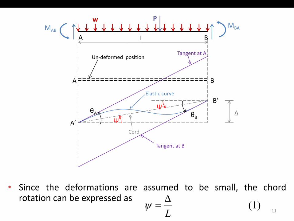
• Since the deformations are assumed to be small, the chordSince the deformations are assumed to be small, the chordrotation can be expressed as
11(1)
L∆
=ψ
Th i ti d i thi h t i f ll• The sign convention used in this chapter is as follows:
“Th b d d i d h d i“The member end moments, end rotations, and chord rotation are positive when counterclockwise.”
• Note that all the moments and rotations are shown in positivesense in figure on previous slide.
• The slope deflection equations can be derived by relating themember end moments to the end rotations and chord rotation bymember end moments to the end rotations and chord rotation byapplying the second moment‐area theorem.
12
w PMAB
MBA
LA BAB
Un‐deformed positionTangent at A
A B
Elastic curve
ΔBA
ΨA’
B’Elastic curve
ΔθA θB
Ψ
Tangent at BΔAB
Cord
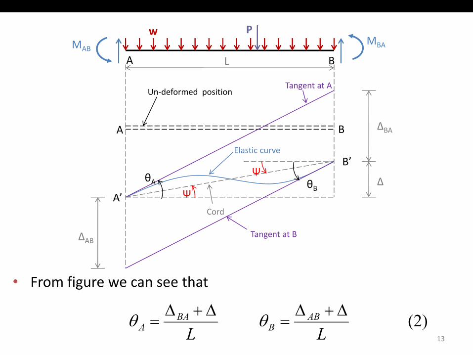
• From figure we can see that
∆∆∆∆13
(2) LL
ABB
BAA
∆+∆=
∆+∆= θθ
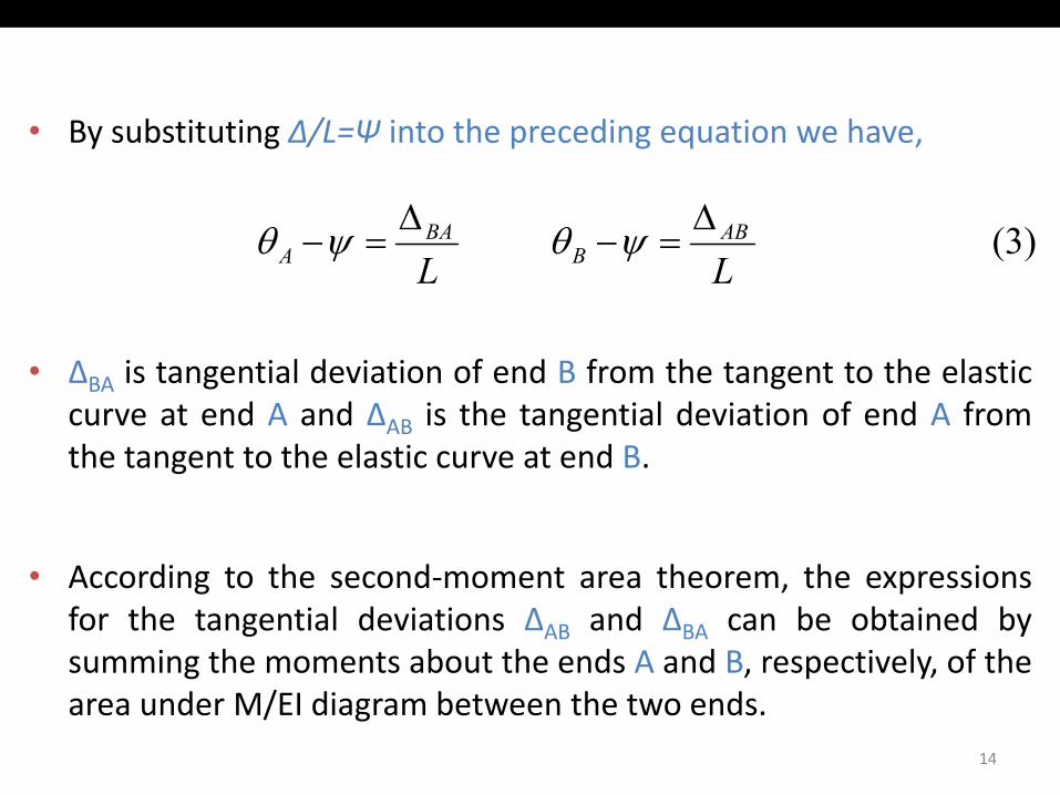
• By substituting Δ/L=Ψ into the preceding equation we have,
( )ABBA ∆∆ θθ (3) LLAB
BBA
A∆
=−∆
=− ψθψθ
• ΔBA is tangential deviation of end B from the tangent to the elasticcurve at end A and ΔAB is the tangential deviation of end A fromthe tangent to the elastic curve at end Bthe tangent to the elastic curve at end B.
A di t th d t th th i• According to the second‐moment area theorem, the expressionsfor the tangential deviations ΔAB and ΔBA can be obtained bysumming the moments about the ends A and B, respectively, of thearea under M/EI diagram between the two ends.
14
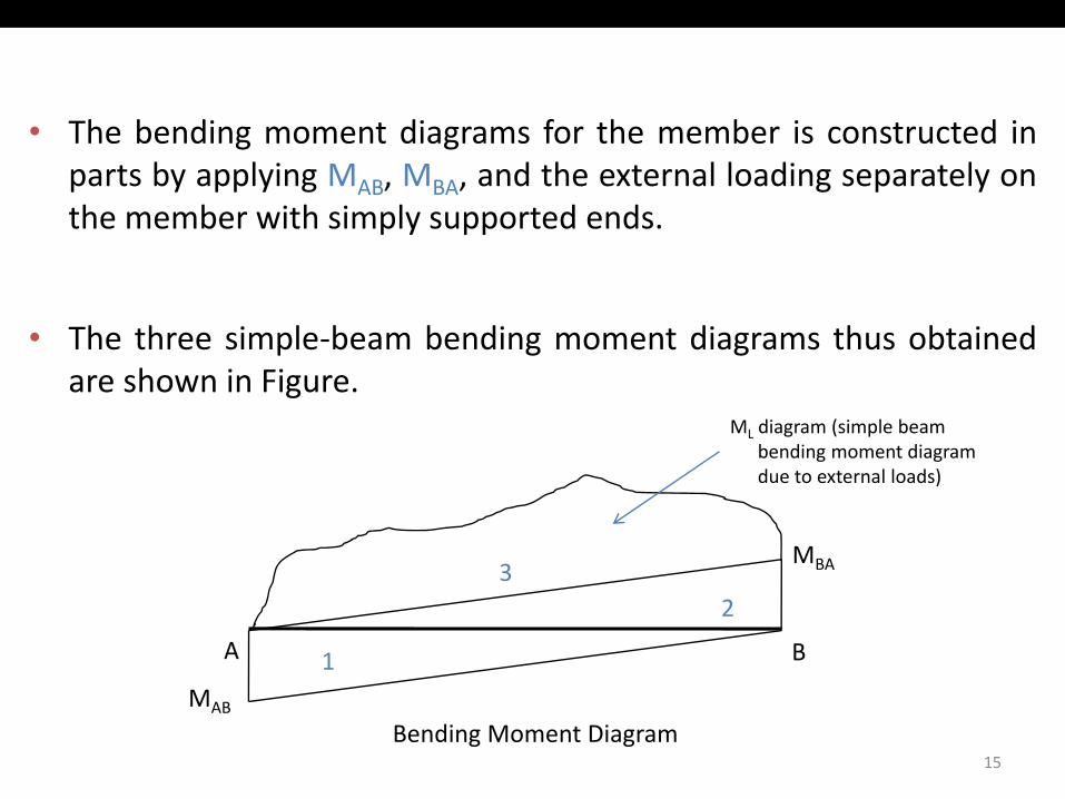
• The bending moment diagrams for the member is constructed inparts by applying MAB, MBA, and the external loading separately onthe member with simply supported ends.the member with simply supported ends.
• The three simple‐beam bending moment diagrams thus obtainedThe three simple beam bending moment diagrams thus obtainedare shown in Figure.
ML diagram (simple beambending moment diagram
MBA3
bending moment diagram due to external loads)
A B1
23
15
MAB
Bending Moment Diagram
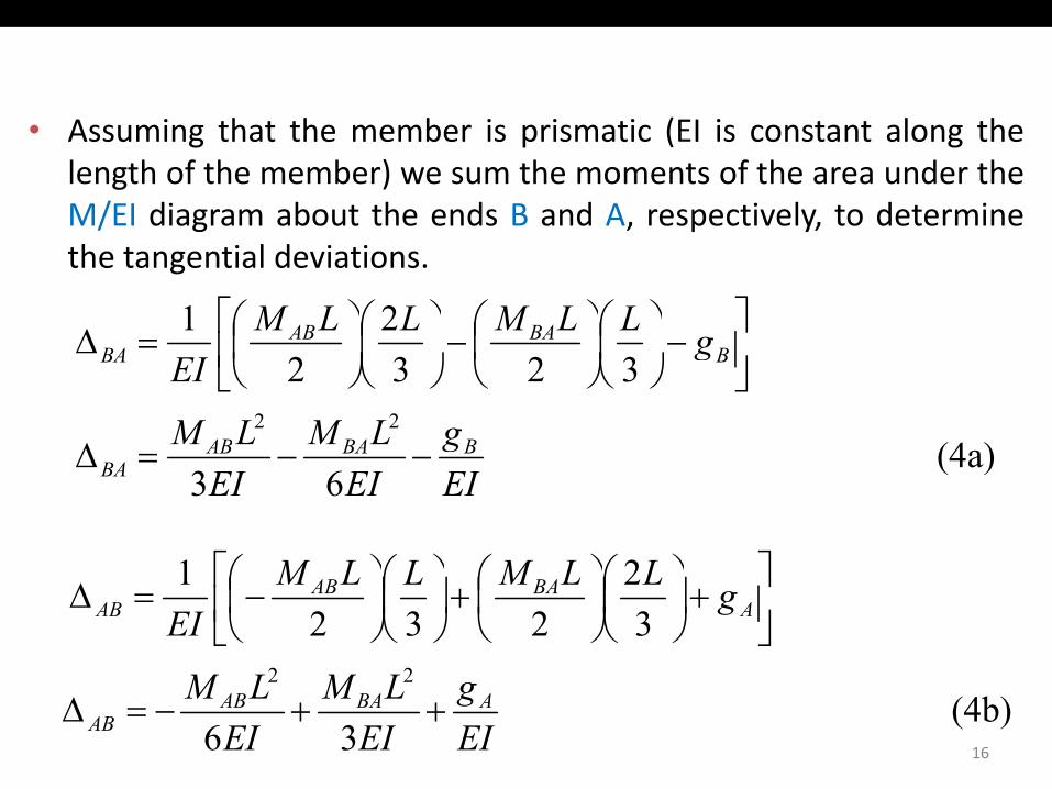
• Assuming that the member is prismatic (EI is constant along thelength of the member) we sum the moments of the area under theM/EI diagram about the ends B and A, respectively, to determineM/EI diagram about the ends B and A, respectively, to determinethe tangential deviations.
∆ BAAB gLLMLLM 21
−
−
=∆ BBAAB
BA gEI 3232
(4a)22 gLMLM BBAAB∆ (4a)
63 EIg
EIEIBBAAB
BA −−=∆
LLMLLM 21
+
+
−=∆ A
BAABAB gLLMLLM
EI 32
2321
22 LMLM16
(4b) 36
22
EIg
EILM
EILM ABAAB
AB ++−=∆
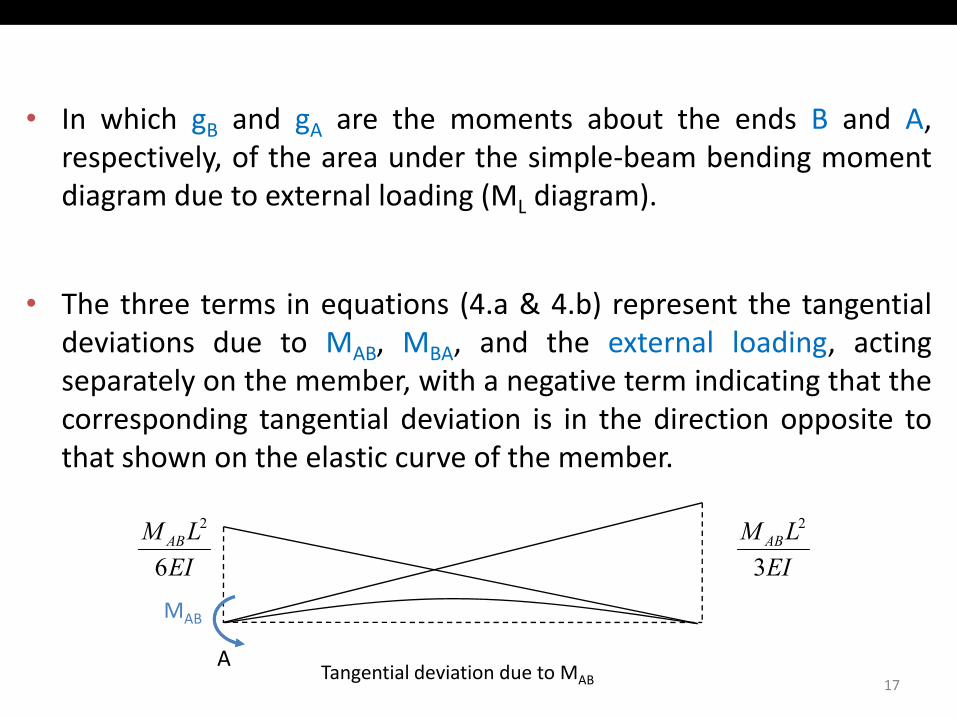
• In which gB and gA are the moments about the ends B and A,respectively, of the area under the simple‐beam bending momentdiagram due to external loading (ML diagram).diagram due to external loading (ML diagram).
• The three terms in equations (4 a & 4 b) represent the tangentialThe three terms in equations (4.a & 4.b) represent the tangentialdeviations due to MAB, MBA, and the external loading, actingseparately on the member, with a negative term indicating that the
di i l d i i i i h di i icorresponding tangential deviation is in the direction opposite tothat shown on the elastic curve of the member.
MAB
EILM AB
6
2
EILM AB
3
2
17
MAB
ATangential deviation due to MAB
BA
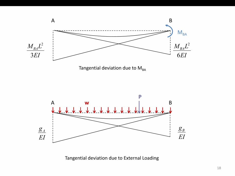
MBA
LM BA2LM BA
2
EI6EI3
Tangential deviation due to MBA
PBA w
EIgB
EIgA
18
Tangential deviation due to External Loading
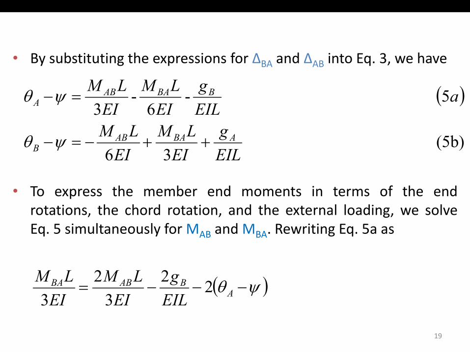
• By substituting the expressions for ΔBA and ΔAB into Eq. 3, we have
( )5-- agLMLM BBAABA =−ψθ ( )
(5b) 36
5 63
EILg
EILM
EILM
aEILEIEI
ABAABB
A
++−=−ψθ
ψθ
• To express the member end moments in terms of the end
36 EILEIEIB
rotations, the chord rotation, and the external loading, we solveEq. 5 simultaneously for MAB and MBA. Rewriting Eq. 5a as
( )ψθ −−−= ABABBA
EILg
EILM
EILM 22
32
3
19
EILEIEI 33
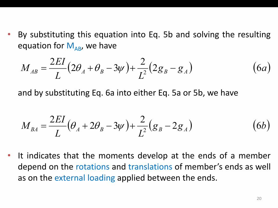
• By substituting this equation into Eq. 5b and solving the resultingequation for MAB, we have
EI 22 ( ) ( ) ( )aggLL
EIM ABBAAB 6 223222 −+−+= ψθθ
and by substituting Eq. 6a into either Eq. 5a or 5b, we have
EI 22 ( ) ( ) ( )bggLL
EIM ABBABA 6 223222 −+−+= ψθθ
• It indicates that the moments develop at the ends of a memberdepend on the rotations and translations of member’s ends as wellas on the external loading applied between the endsas on the external loading applied between the ends.
20
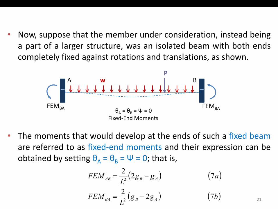
• Now, suppose that the member under consideration, instead beinga part of a larger structure, was an isolated beam with both endscompletely fixed against rotations and translations, as shown.completely fixed against rotations and translations, as shown.
BA wP
θA = θB = Ψ = 0Fixed‐End Moments
FEMBAFEMBA
• The moments that would develop at the ends of such a fixed beamare referred to as fixed‐end moments and their expression can be
Fixed End Moments
are referred to as fixed end moments and their expression can beobtained by setting θA = θB = Ψ = 0; that is,
( ) ( )aggFEM ABAB 7 222 −=
21
( ) ( )
( ) ( )bggL
FEM
ggL
ABBA
ABAB
7 222
2
−=
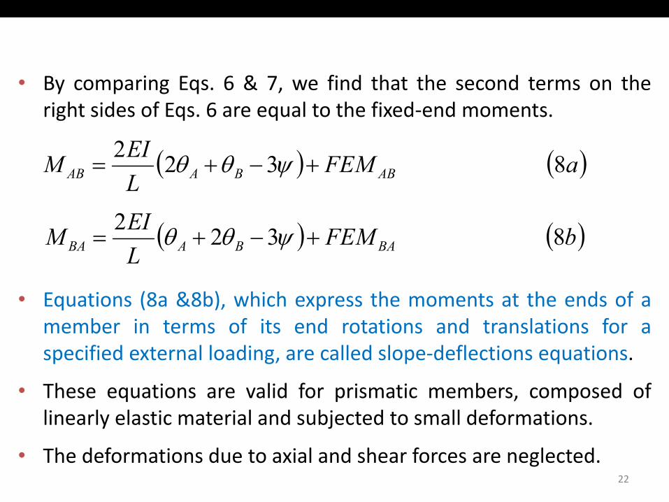
• By comparing Eqs. 6 & 7, we find that the second terms on theright sides of Eqs. 6 are equal to the fixed‐end moments.
EI2 ( ) ( )aFEMLEIM ABBAAB 8 322
+−+= ψθθ
EI2 ( ) ( )bFEMLEIM BABABA 8 322
+−+= ψθθ
• Equations (8a &8b), which express the moments at the ends of amember in terms of its end rotations and translations for aspecified external loading, are called slope‐deflections equations.specified external loading, are called slope deflections equations.
• These equations are valid for prismatic members, composed oflinearly elastic material and subjected to small deformations.
• The deformations due to axial and shear forces are neglected.22
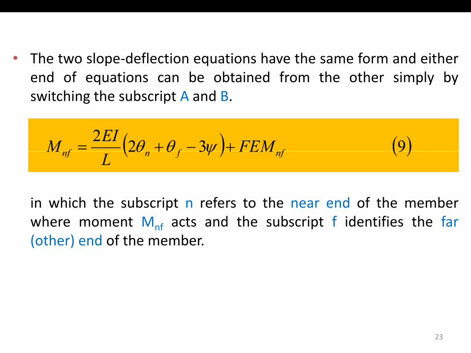
• The two slope‐deflection equations have the same form and eitherend of equations can be obtained from the other simply byswitching the subscript A and B.switching the subscript A and B.
( ) ( )9322fff FEMEIM +−+= ψθθ
in which the subscript n refers to the near end of the member
( ) ( )9 32 nffnnf FEML
M ++ ψθθ
in which the subscript n refers to the near end of the memberwhere moment Mnf acts and the subscript f identifies the far(other) end of the member.
23
Members with One End Hinged
• The slope deflection equations derived previously are based on thecondition that the member is rigidly connected to joints at bothg y jends, so that the member end rotations θA and θB are equal to therotations of the adjacent joints.
• When one of the member’s ends is connected to the adjacent jointby a hinged connection, the moment at the hinged end must beby a hinged connection, the moment at the hinged end must bezero.
• The slope‐deflections equations can be easily modified to reflectthis condition.
24
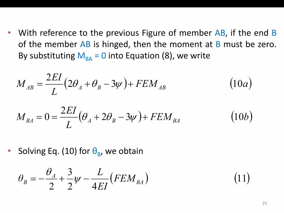
With f t th i Fi f b AB if th d B• With reference to the previous Figure of member AB, if the end Bof the member AB is hinged, then the moment at B must be zero.By substituting MBA = 0 into Equation (8), we write
( ) ( )aFEMLEIM ABBAAB 10 322
+−+= ψθθL
( ) ( )bFEMLEIM BABABA 10 3220 +−+== ψθθ
• Solving Eq (10) for θ we obtain
( ) ( )L BABABA ψ
Solving Eq. (10) for θB, we obtain
( ) ( )11 3 FEMLθ BAA
B −+−= ψθ
25
( ) ( )422 EI BAB ψ
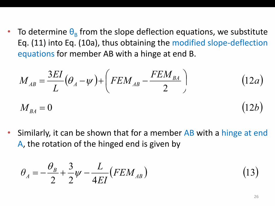
T d t i θ f th l d fl ti ti b tit t• To determine θB from the slope deflection equations, we substituteEq. (11) into Eq. (10a), thus obtaining the modified slope‐deflectionequations for member AB with a hinge at end B.
( ) ( )aFEMFEMLEIM BA
ABAAB 12 2
3
−+−= ψθ
L 2
( )bM BA 12 0=
• Similarly, it can be shown that for a member AB with a hinge at endA, the rotation of the hinged end is given by, g g y
( ) ( )13 3 FEMLθ ABB
A −+−= ψθ
26
( ) ( )422 EI ABA ψ
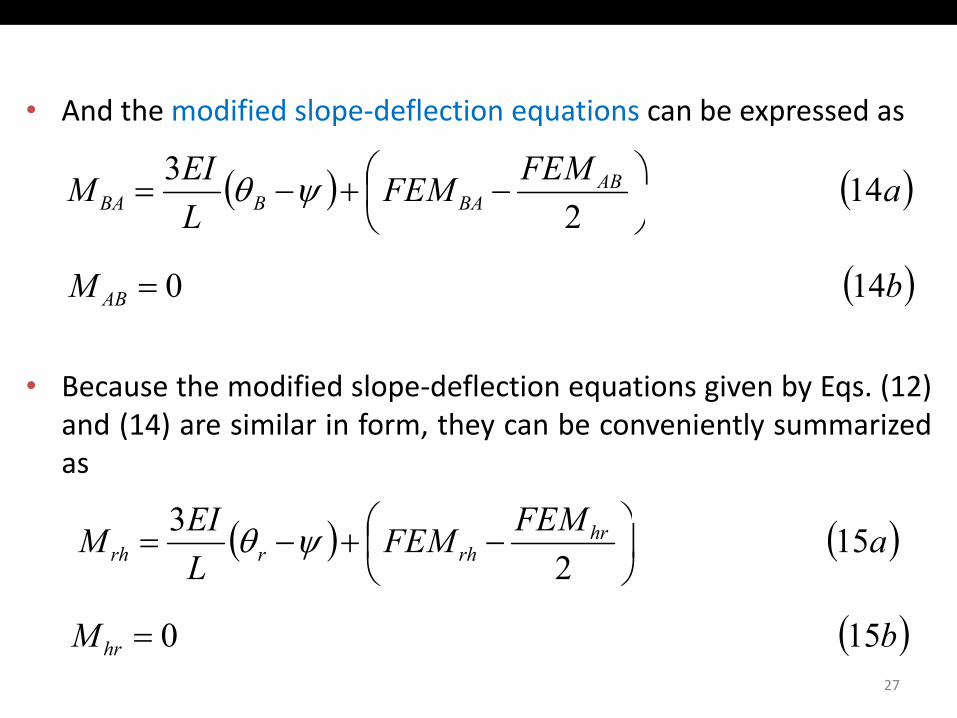
A d th difi d l d fl ti ti b d• And the modified slope‐deflection equations can be expressed as
( ) ( )aFEMFEMEIM ABBABBA 14
23
−+−= ψθ( ) ( )
L BABBA 2
ψ
( )bM AB 14 0=
• Because the modified slope‐deflection equations given by Eqs. (12)and (14) are similar in form, they can be conveniently summarizedas
FEMEI3 ( ) ( )aFEMFEMLEIM hr
rhrrh 15 2
3
−+−= ψθ
( )27
( )bM hr 15 0=
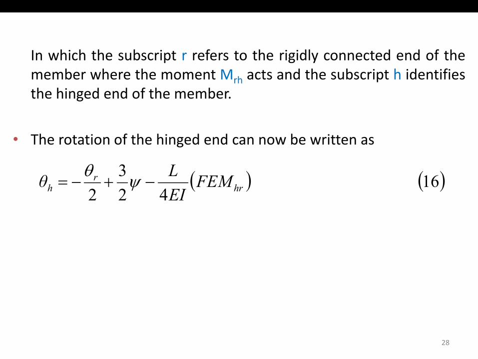
I hi h th b i t f t th i idl t d d f thIn which the subscript r refers to the rigidly connected end of themember where the moment Mrh acts and the subscript h identifiesthe hinged end of the member.
• The rotation of the hinged end can now be written as
( ) ( )16 42
32
FEMEILθ hr
rh −+−= ψθ
28
Basic Concept of the Slope‐Deflection Method
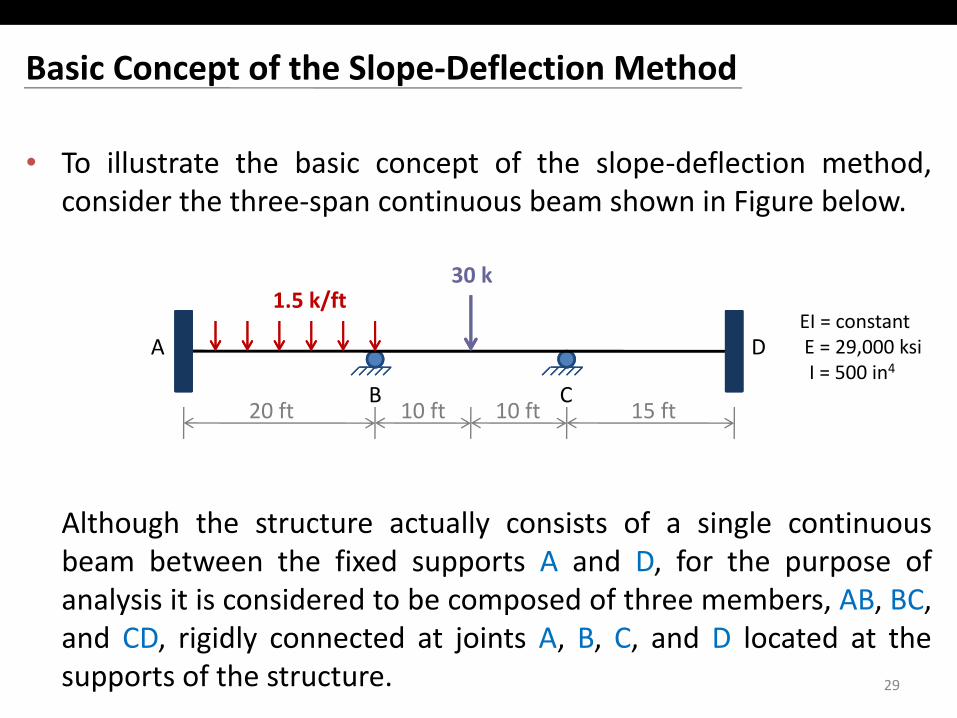
• To illustrate the basic concept of the slope‐deflection method,consider the three‐span continuous beam shown in Figure belowconsider the three span continuous beam shown in Figure below.
1.5 k/ft30 k
B C20 ft
DA
10 ft 10 ft 15 ft
1.5 k/ftEI = constantE = 29,000 ksiI = 500 in4
Al h h h ll i f i l i
20 ft 10 ft 10 ft 15 ft
Although the structure actually consists of a single continuousbeam between the fixed supports A and D, for the purpose ofanalysis it is considered to be composed of three members, AB, BC,and CD, rigidly connected at joints A, B, C, and D located at thesupports of the structure. 29
Degrees of Freedom
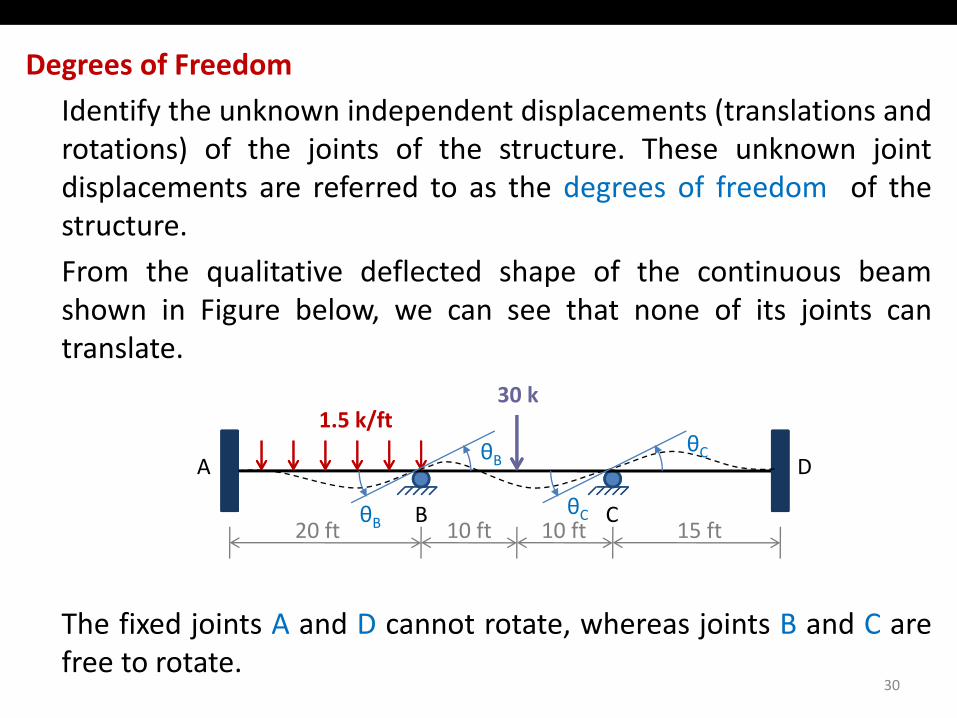
Id tif th k i d d t di l t (t l ti dIdentify the unknown independent displacements (translations androtations) of the joints of the structure. These unknown jointdisplacements are referred to as the degrees of freedom of thestructure.
From the qualitative deflected shape of the continuous beamshown in Figure below we can see that none of its joints canshown in Figure below, we can see that none of its joints cantranslate.
/30 k
B C
DA
1.5 k/ft
θ
θB
θC
θC
Th fi d j i t A d D t t t h j i t B d C
B C20 ft 10 ft 10 ft 15 ft
θBθC
The fixed joints A and D cannot rotate, whereas joints B and C arefree to rotate.
30
Degrees of Freedom30 k
DA
1.5 k/ft30 k
θBθC
B C20 ft 10 ft 10 ft 15 ft
θBθC
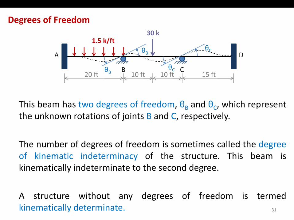
This beam has two degrees of freedom, θB and θC, which representthe unknown rotations of joints B and C, respectively.
The number of degrees of freedom is sometimes called the degreeof kinematic indeterminacy of the structure This beam isof kinematic indeterminacy of the structure. This beam iskinematically indeterminate to the second degree.
A structure without any degrees of freedom is termedkinematically determinate. 31
Equations of Equilibrium
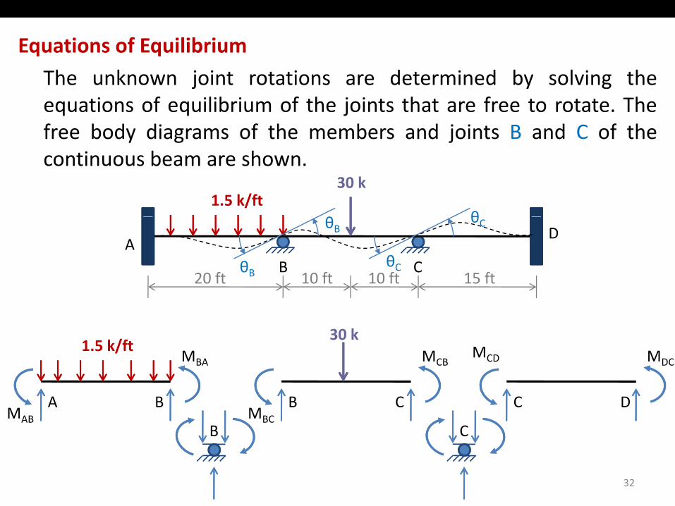
Th k j i t t ti d t i d b l i thThe unknown joint rotations are determined by solving theequations of equilibrium of the joints that are free to rotate. Thefree body diagrams of the members and joints B and C of thecontinuous beam are shown.
1.5 k/ft30 k
θ θ
B C20 ft
DA
10 ft 10 ft 15 ftθB
θB
θC
θC
MBA MCB
30 k1.5 k/ft MCD MDC
A BMAB
MBA
B CMBC
MCB
C D
CD MDC
B C
32
B C
Equations of Equilibrium
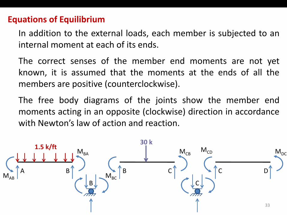
I dditi t th t l l d h b i bj t d tIn addition to the external loads, each member is subjected to aninternal moment at each of its ends.
The correct senses of the member end moments are not yetThe correct senses of the member end moments are not yetknown, it is assumed that the moments at the ends of all themembers are positive (counterclockwise).
The free body diagrams of the joints show the member endmoments acting in an opposite (clockwise) direction in accordancewith Newton’s law of action and reactionwith Newton s law of action and reaction.
MBA MCB
30 k1.5 k/ft MCD MDC
A BMAB
MBA
B CMBC
MCB
C D
CD MDC
B C
33
B C
Equations of Equilibrium
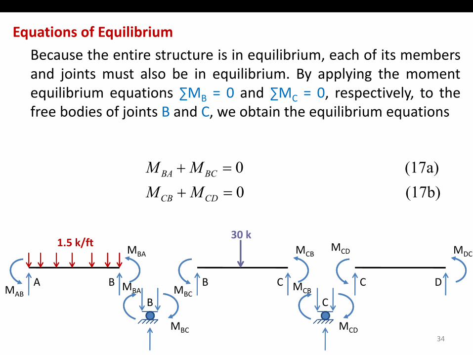
B th ti t t i i ilib i h f it bBecause the entire structure is in equilibrium, each of its membersand joints must also be in equilibrium. By applying the momentequilibrium equations ∑MB = 0 and ∑MC = 0, respectively, to theB Cfree bodies of joints B and C, we obtain the equilibrium equations
(17b) 0(17a) 0
=+=+
CDCB
BCBA
MMMM
MBA MCB
30 k1.5 k/ft MCD MDC
A BMAB
MBA
B CMBC
MCB
C D
CD MDC
B CMBA MCB
34
B C
MBC MCD
Slope‐Deflection Equations
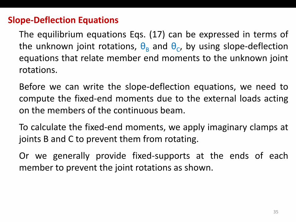
Th ilib i ti E (17) b d i t fThe equilibrium equations Eqs. (17) can be expressed in terms ofthe unknown joint rotations, θB and θC, by using slope‐deflectionequations that relate member end moments to the unknown jointrotations.
Before we can write the slope‐deflection equations, we need toh fi d d d h l l d icompute the fixed‐end moments due to the external loads acting
on the members of the continuous beam.
To calculate the fixed end moments we apply imaginary clamps atTo calculate the fixed‐end moments, we apply imaginary clamps atjoints B and C to prevent them from rotating.
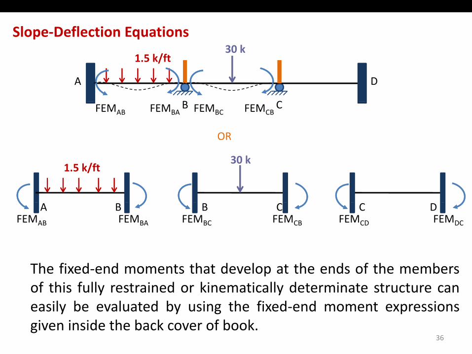
Or we generally provide fixed‐supports at the ends of eachOr we generally provide fixed supports at the ends of eachmember to prevent the joint rotations as shown.
35
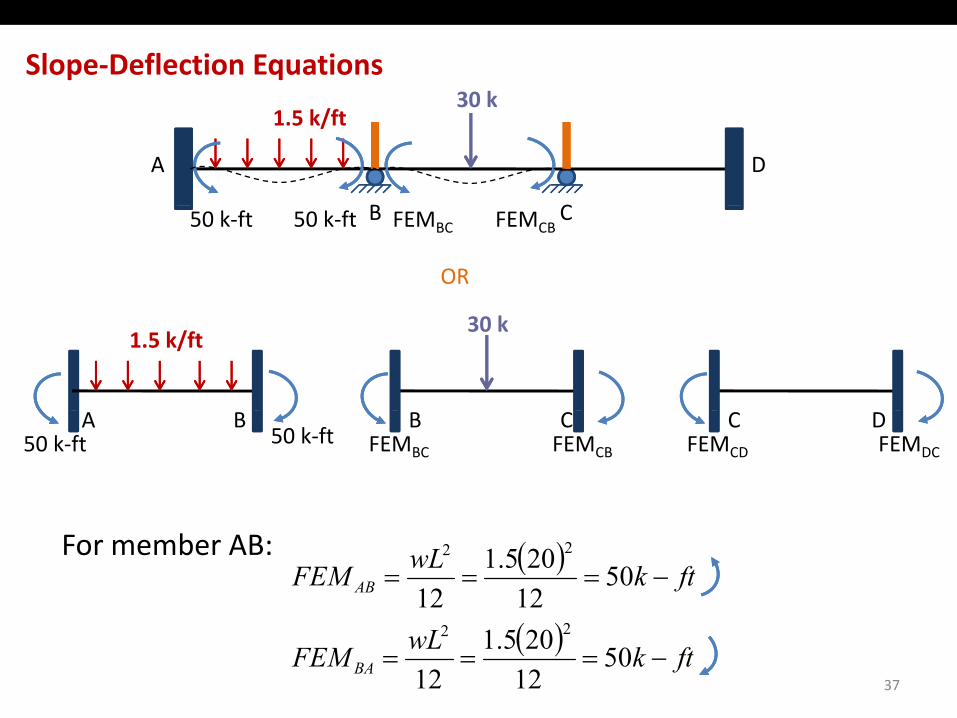
Slope‐Deflection Equations30 k
B C
DA
1.5 k/ft30 k
B C
OR
FEMAB FEMBA FEMBC FEMCB
1.5 k/ft30 k
CBA B C DFEMAB FEMBA FEMBC FEMCB FEMCD FEMDC
The fixed‐end moments that develop at the ends of the membersof this fully restrained or kinematically determinate structure can
il b l t d b i th fi d d t ieasily be evaluated by using the fixed‐end moment expressionsgiven inside the back cover of book.
36
Slope‐Deflection Equations30 k
B C
DA
1.5 k/ft30 k
B C
OR
FEMBC FEMCB50 k‐ft 50 k‐ft
1.5 k/ft30 k
CBA B C DFEMBC FEMCB FEMCD FEMDC50 k‐ft 50 k‐ft
For member AB: ( ) ftkwLFEM AB −=== 5012205.1
12
22
37
( ) ftkwLFEM BA −=== 5012205.1
12
22

Slope‐Deflection Equations30 k
B C
DA
1.5 k/ft30 k
75 k ft 75 k ftB C
OR
50 k‐ft 50 k‐ft 75 k‐ft 75 k‐ft
1.5 k/ft30 k
CBA B C D0 050 k‐ft 50 k‐ft 75 k‐ft 75 k‐ft
For member BC: ( ) ftkPLFEM BC −=== 7582030
8
38
( ) ftkPLFEMCB −=== 7582030
8
Slope‐Deflection Equations
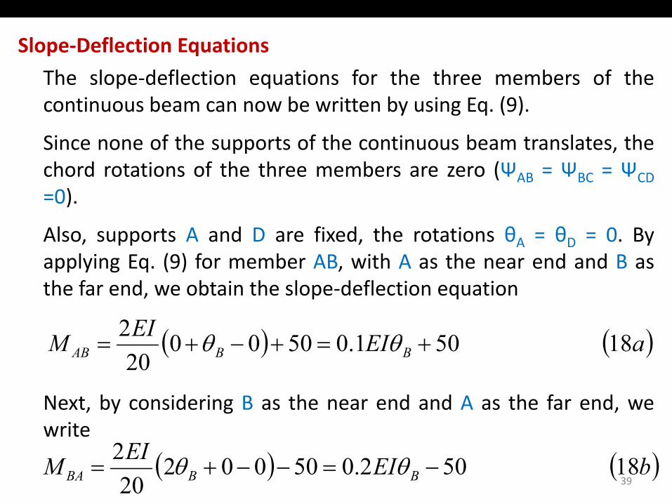
Th l d fl ti ti f th th b f thThe slope‐deflection equations for the three members of thecontinuous beam can now be written by using Eq. (9).
Since none of the supports of the continuous beam translates theSince none of the supports of the continuous beam translates, thechord rotations of the three members are zero (ΨAB = ΨBC = ΨCD=0).
Also, supports A and D are fixed, the rotations θA = θD = 0. Byapplying Eq. (9) for member AB, with A as the near end and B asthe far end we obtain the slope deflection equationthe far end, we obtain the slope‐deflection equation
( ) ( )aEIEIM BBAB 18 501.0500020
2+=+−+= θθ
Next, by considering B as the near end and A as the far end, wewrite
20
write
39( ) ( )bEIEIM BBBA 18 502.050002
202
−=−−+= θθ
Slope‐Deflection Equations
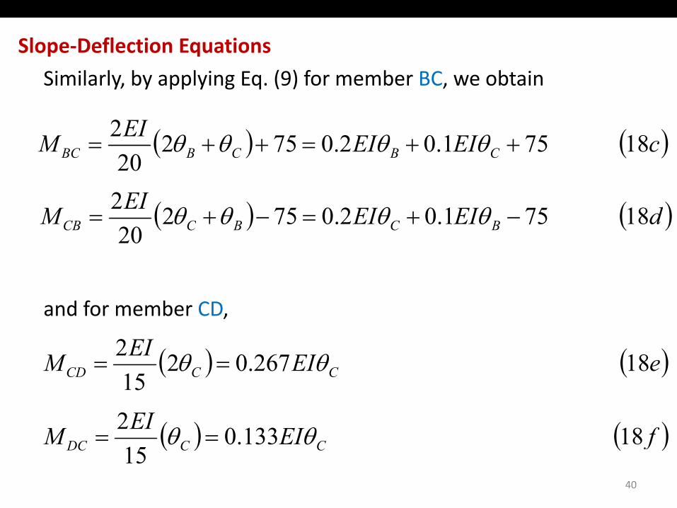
Si il l b l i E (9) f b BC bt iSimilarly, by applying Eq. (9) for member BC, we obtain
( ) ( )cEIEIEIM 185710207522++=++= θθθθ( ) ( )cEIEIM CBCBBC 18 571.02.0752
20++=++= θθθθ
( ) ( )dEIEIEIM 185710207522−+=−+= θθθθ( ) ( )dEIEIM BCBCCB 18 571.02.0752
20−+=−+= θθθθ
and for member CD,
( ) ( )eEIEIM 18267022 θθ == ( ) ( )eEIM CCCD 18 267.0215
θθ ==
( ) ( )fEIEIM 1813302 θθ ==
40
( ) ( )fEIM CCDC 18 133.015
θθ ==
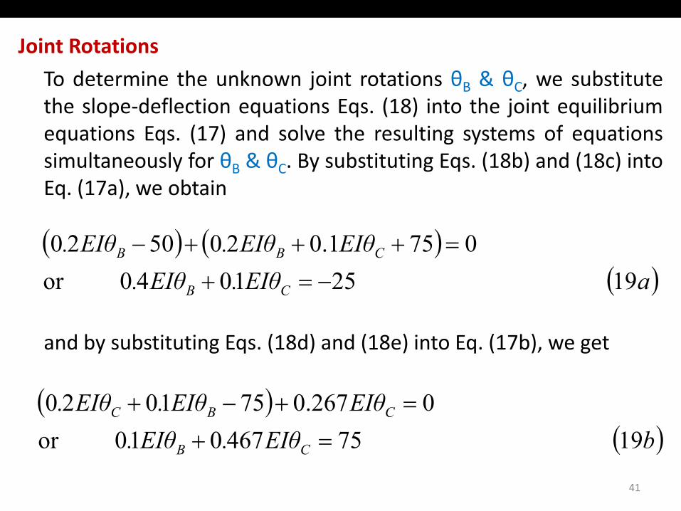
Joint Rotations
T d t i th k j i t t ti θ & θ b tit tTo determine the unknown joint rotations θB & θC, we substitutethe slope‐deflection equations Eqs. (18) into the joint equilibriumequations Eqs. (17) and solve the resulting systems of equationssimultaneously for θB & θC. By substituting Eqs. (18b) and (18c) intoEq. (17a), we obtain
( ) ( )( )aEIθ.EIθ.
EIθEIθ.EIθ.
CB
CBB
19 251040or 0751.0205020
−=+=+++−
and by substituting Eqs. (18d) and (18e) into Eq. (17b), we get
( )CB
( )( )bEIθEIθ
EIθEIθ.EIθ. CBC
1975467010or0267.0751020
+=+−+
41
( )bEIθ.EIθ. CB 19 75467010or =+
Joint Rotations
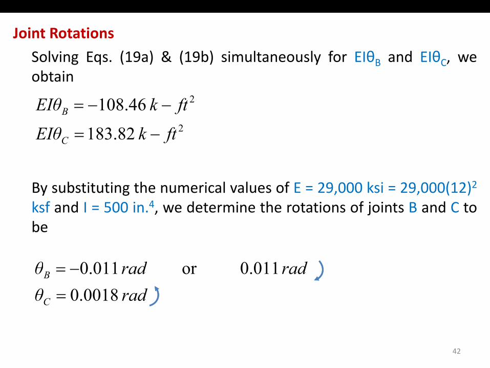
S l i E (19 ) & (19b) i lt l f EIθ d EIθSolving Eqs. (19a) & (19b) simultaneously for EIθB and EIθC, weobtain
246108 ftkEIθ =2 82.183
46.108
ftkEIθftkEIθ
C
B
−=
−−=
By substituting the numerical values of E = 29,000 ksi = 29,000(12)2
ksf and I = 500 in 4 we determine the rotations of joints B and C toksf and I 500 in. , we determine the rotations of joints B and C tobe
ddθ 0 0110110radθ
radradθ
C
B
0018.00.011 or 011.0
=−=
42
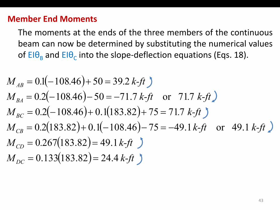
Member End Moments
Th t t th d f th th b f th tiThe moments at the ends of the three members of the continuousbeam can now be determined by substituting the numerical valuesof EIθB and EIθC into the slope‐deflection equations (Eqs. 18).B C
( ) 239504610810 k-ft ...M AB =+−=( )( ) ( ) 7717582.1831.04610820
771or 7.71504610820 k-ft...M
k-ft.k-ft ..M
BC
BA
=++−=−=−−=
( ) ( )( ) 1.4982.1832670
49.1or 1.497546.1081.082.18320k-ft.M
k-ftk-ft .M
CD
CB
==−=−−+=
( ) 4.2482.183133.0 k-ftM DC ==
43
Member End Moments
T h k th t th l ti f i lt ti (E 19) hTo check that the solution of simultaneous equations (Eqs. 19) hasbeen carried out correctly, the numerical values of member endmoments should be substituted into the joint equilibriumequations (Eqs. 17). If the solution is correct, then the equilibriumequations should be satisfied.
ChecksMMChecksMM
CDCB
BCBA
01.491.49 07.717.71
=+−=+=+−=+
The member end moments just computed are shown on the freeb d di f th b d j i t i Fi t lidbody diagrams of the members and joints in Figure on next slide.
44
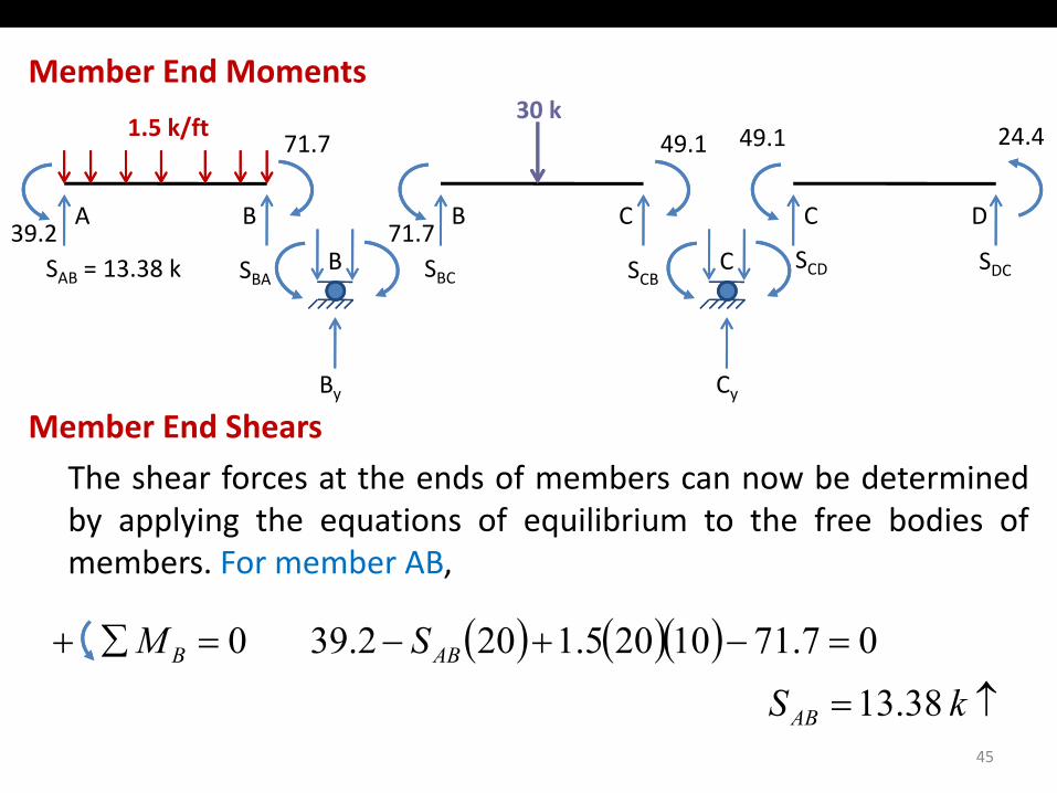
Member End Moments30 k
A B39 2
71.7
B C71 7
49.130 k
1.5 k/ft
C D
49.1 24.4
39.2 71.7B CSAB = 13.38 k SBA SBC SCB
SCD SDC
Member End ShearsBy Cy
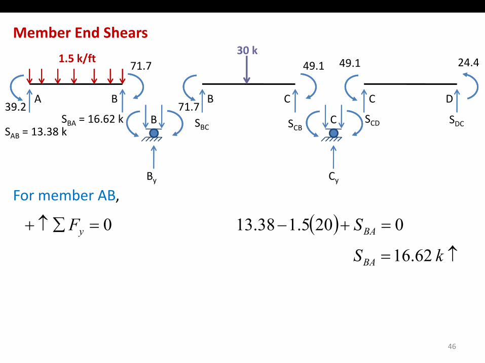
The shear forces at the ends of members can now be determinedby applying the equations of equilibrium to the free bodies ofmembers For member ABmembers. For member AB,
( ) ( )( ) =−+−=∑+ SM ABB 07.7110205.1202.39 0
45
↑= kSAB 38.13
Member End Shears30 k
A B39 2
71.7
B C71 7
49.130 k
1.5 k/ft
C D
49.1 24.4
39.2 71.7B CSBA = 16.62 k SBC SCB
SCD SDCSAB = 13.38 k
For member AB,By Cy
( )↑=
=+−=∑↑+
kS
SF
BA
BAy
6216
0205.13.381 0
↑kSBA 62.16
46
Member End Shears30 k
A B39 2
71.7
B C71 7
49.130 k
1.5 k/ft
C D
49.1 24.4
39.2 71.7B CSBA = 16.62 k
SBC = 16.13 kSCB = 13.87 k SCD SDC
SAB = 13.38 k
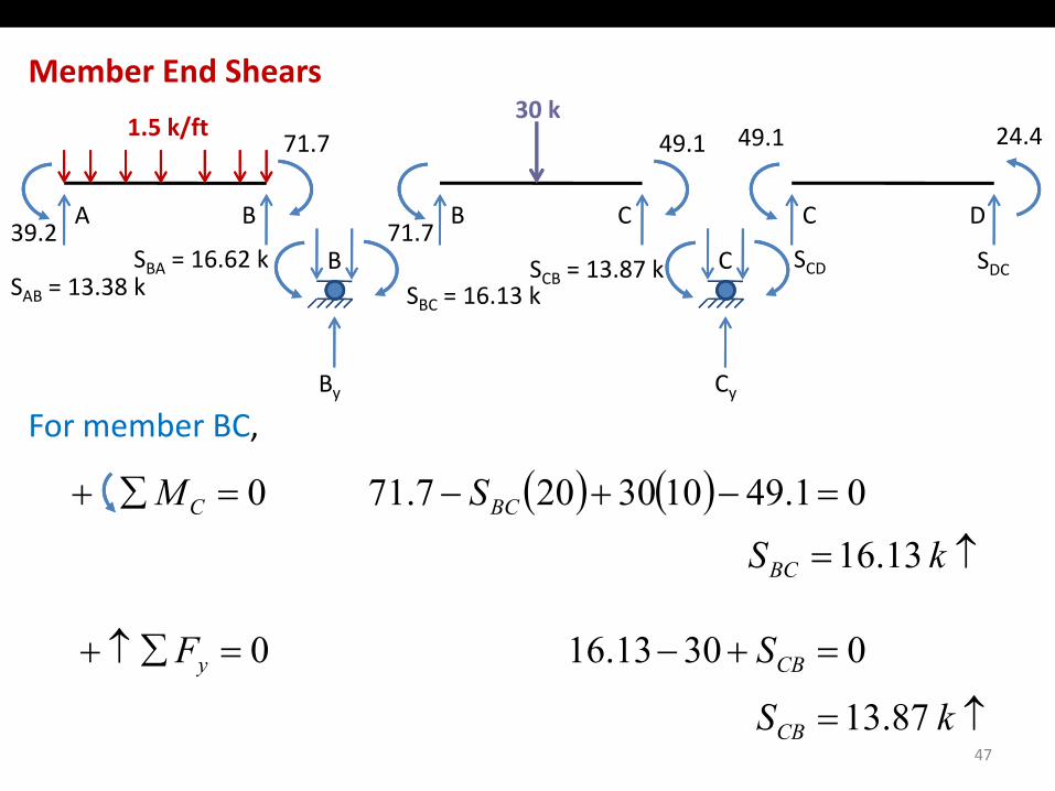
For member BC,By Cy
( ) ( )↑=
=−+−=∑+
kSSM
BC
BCC
13.16
01.491030201.77 0
=+−=∑↑+ SF CBy 0306.131 0
↑kSBC 13.16
47
↑= kSCB 87.13
Member End Shears30 k
A B39 2
71.7
B C71 7
49.130 k
1.5 k/ft
C D
49.1 24.4
39.2 71.7B CSBA = 16.62 k
SBC = 16.13 kSCB = 13.87 k SCD = 4.9 k SDC = 4.9 k
SAB = 13.38 k
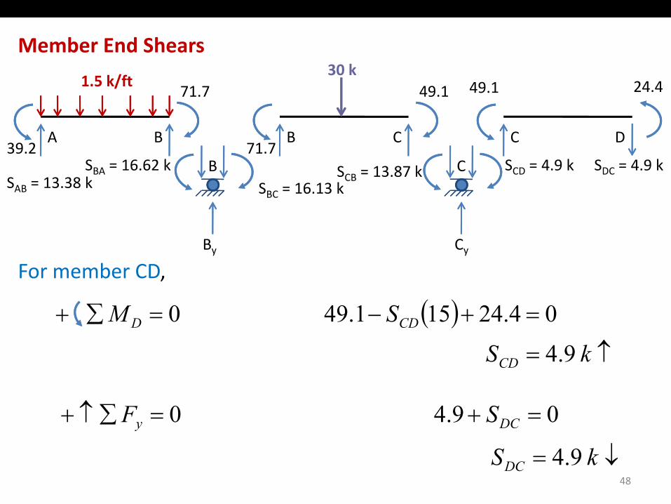
For member CD,By Cy
( )↑=
=+−=∑+
kSSM
CD
CDD
9.4
04.24159.14 0
=+=∑↑+ SF DCy 0.94 0
↑kSCD 9.4
48
↓= kSDC 9.4
Support Reactions30 k
A B39 2
71.7
B C71 7
49.130 k
1.5 k/ft
C D
49.1 24.4
16 62 k16.13 k39.2 71.7B CSBA = 16.62 k
SBC = 16.13 kSCB = 13.87 k SCD = 4.9 k SDC = 4.9 k
SAB = 13.38 k
16.62 k16.13 k
By = 32.75 k Cy
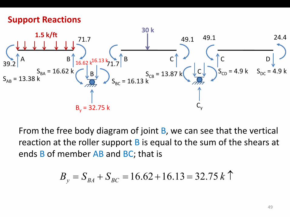
From the free body diagram of joint B, we can see that the vertical reaction at the roller support B is equal to the sum of the shears at ends B of member AB and BC; that isends B of member AB and BC; that is
↑=+=+= kSSB BCBAy 75.3213.1662.16
49
Support Reactions30 k
A B39 2
71.7
B C71 7
49.130 k
1.5 k/ft
C D
49.1 24.4
16 62 k16.13 k 13 87 k 4.9 k39.2 71.7B CSBA = 16.62 k
SBC = 16.13 kSCB = 13.87 k SCD = 4.9 k SDC = 4.9 k
SAB = 13.38 k
16.62 k16.13 k 13.87 k 4.9 k
By = 32.75 k Cy = 18.77 k
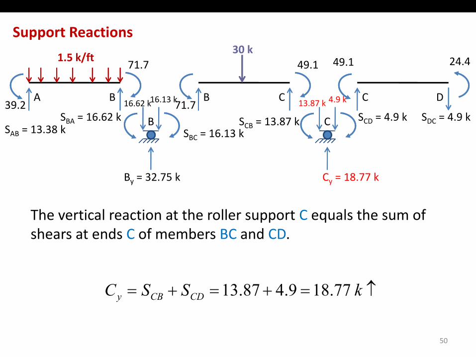
The vertical reaction at the roller support C equals the sum of shears at ends C of members BC and CD.
↑=+=+= kSSC CDCBy 77.189.487.13
50
Support Reactions
1 5 k/ft30 k
B C
DA
1.5 k/ft
B C
32.75 k 18.77 k
51
Support Reactions30 k
B C
DA
1.5 k/ft30 k
39 2 k f B C
32.75 k 18.77 k13.38 k
39.2 k‐ft
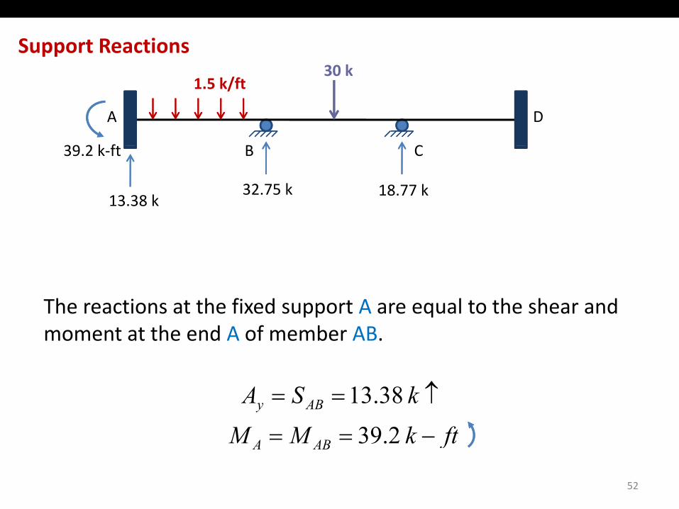
The reactions at the fixed support A are equal to the shear and moment at the end A of member AB.
ftkMMkSA ABy
==
↑==
239 38.13
52
ftkMM ABA −== 2.39
Support Reactions30 k
B C
DA
1.5 k/ft30 k
39 2 k f
24.4 k‐ft
B C
32.75 k 18.77 k13.38 k
39.2 k‐ft
4.9 k
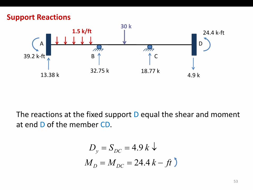
The reactions at the fixed support D equal the shear and moment at end D of the member CD.
ftkMMkSD DCy
==
↓==
424 9.4
53
ftkMM DCD −== 4.24
Equilibrium Check30 k
B C
DA
1.5 k/ft30 k
39 2 k f
24.4 k‐ft
B C
32.75 k 18.77 k13.38 k
39.2 k‐ft
4.9 k
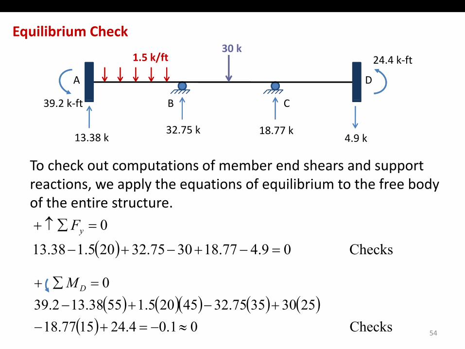
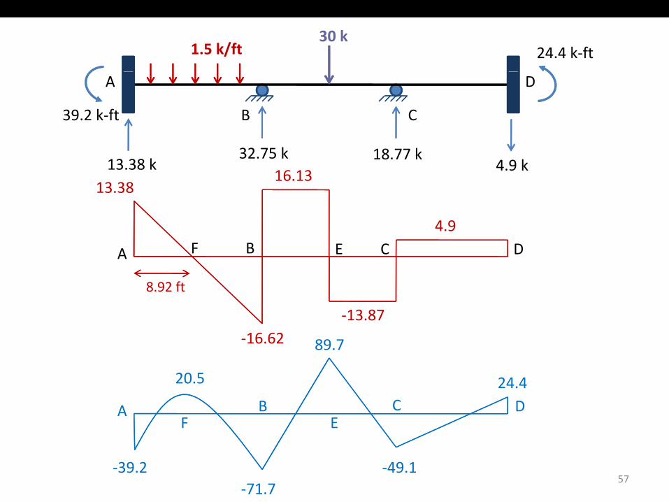
To check out computations of member end shears and support reactions, we apply the equations of equilibrium to the free body
f th ti t tof the entire structure.
( ) Checks0947718307532205138130
=++
=∑↑+ yF
( ) ( )( ) ( ) ( )0 =∑+ DM
( ) Checks 09.477.183075.32205.138.13 =−+−+−
( ) ( )( ) ( ) ( )( ) Checks 01.04.241577.18
25303575.3245205.15538.132.39≈−=+−
+−+−
54
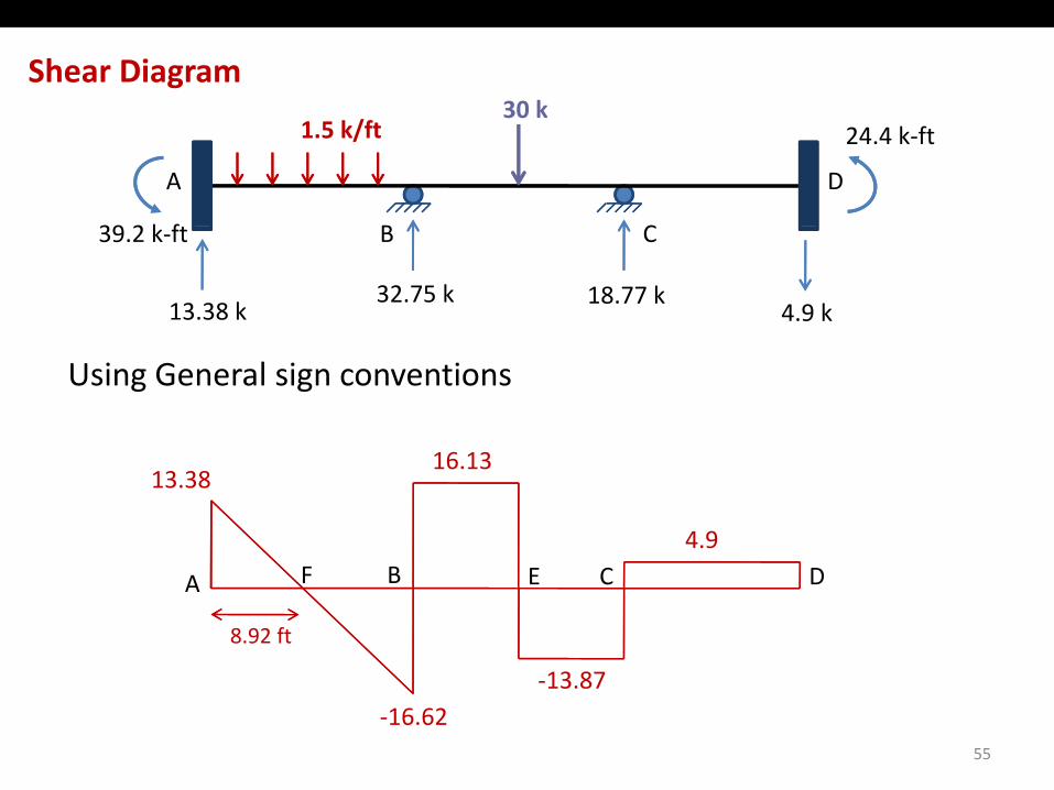
Shear Diagram30 k
B C
DA
1.5 k/ft30 k
39 2 k f
24.4 k‐ft
B C
32.75 k 18.77 k13.38 k
39.2 k‐ft
4.9 k
Using General sign conventions
13.38 16.13
4.9
13 87
A B C DEF
8.92 ft
55
‐16.62‐13.87
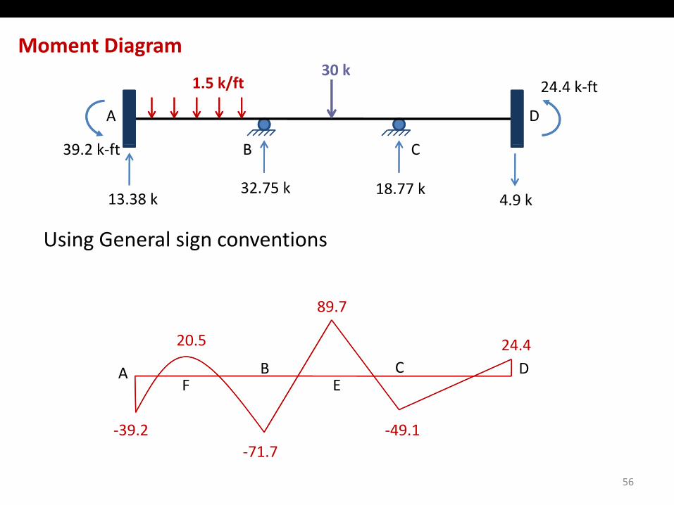
Moment Diagram30 k
B C
DA
1.5 k/ft30 k
39 2 k f
24.4 k‐ft
B C
32.75 k 18.77 k13.38 k
39.2 k‐ft
4.9 k
Using General sign conventions
24.4
89.7
20.5
‐39 2
AEF
B C D
‐49 1
56
39.2‐71.7
49.1
1.5 k/ft30 k
24.4 k‐ft
B C
DA
39.2 k‐ft
32.75 k 18.77 k13.38 k 4.9 k
13.38 16.13
4.9
A B C DEF
8 92 ft
‐16.62‐13.87
8.92 ft
89.7
24.4
AEF
B C D
20.5
57‐39.2
‐71.7‐49.1
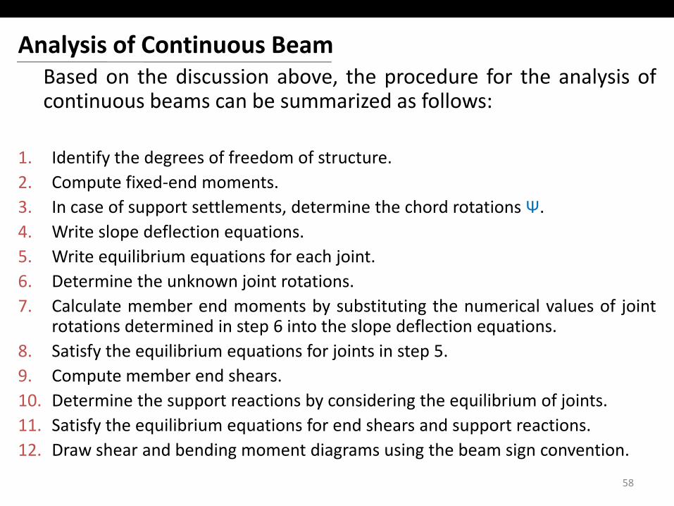
Analysis of Continuous BeamB d th di i b th d f th l i fBased on the discussion above, the procedure for the analysis ofcontinuous beams can be summarized as follows:
1. Identify the degrees of freedom of structure.2. Compute fixed‐end moments.3. In case of support settlements, determine the chord rotations Ψ.4. Write slope deflection equations.5. Write equilibrium equations for each joint.6. Determine the unknown joint rotations.j7. Calculate member end moments by substituting the numerical values of joint
rotations determined in step 6 into the slope deflection equations.8. Satisfy the equilibrium equations for joints in step 5.9. Compute member end shears.10. Determine the support reactions by considering the equilibrium of joints.11. Satisfy the equilibrium equations for end shears and support reactions.y q q pp12. Draw shear and bending moment diagrams using the beam sign convention.
58
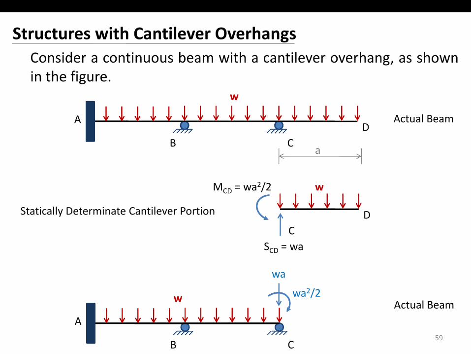
Structures with Cantilever OverhangsConsider a continuous beam with a cantilever overhang, as shownin the figure.
w
B CD
A
a
Actual Beam
a
wMCD = wa2/2
CD
SCD = wa
Statically Determinate Cantilever Portion
CD
w Actual Beam
wa
wa2/2
59B C
AActual Beam
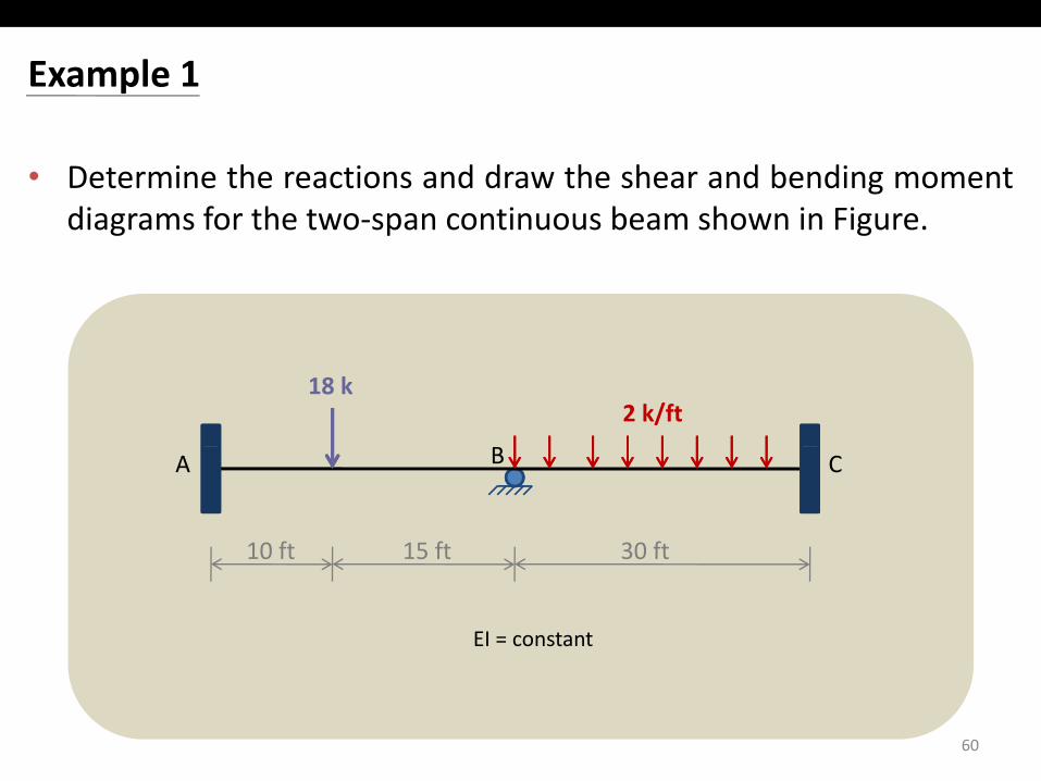
Example 1
• Determine the reactions and draw the shear and bending momentdiagrams for the two‐span continuous beam shown in Figurediagrams for the two span continuous beam shown in Figure.
2 k/ft18 k
B CA
10 ft 15 ft 30 ft
EI = constant
10 ft 15 ft 30 ft
60
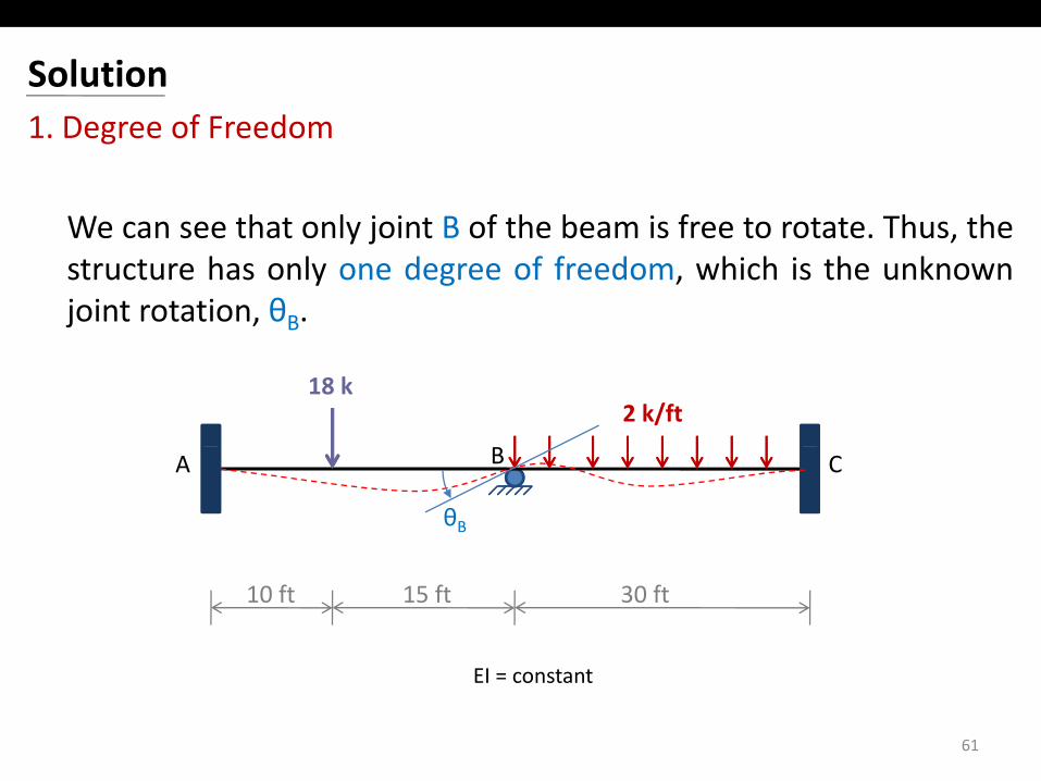
Solution1. Degree of Freedom
We can see that only joint B of the beam is free to rotate Thus theWe can see that only joint B of the beam is free to rotate. Thus, thestructure has only one degree of freedom, which is the unknownjoint rotation, θB.
2 k/ft18 k
B CA
θB
EI
10 ft 15 ft 30 ft
61
EI = constant
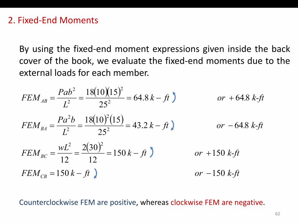
2. Fixed‐End Moments
By using the fixed‐end moment expressions given inside the backcover of the book, we evaluate the fixed‐end moments due to the,external loads for each member.
( )( ) k ftftkPabFEM 864864151018 22
+( )( )
( ) ( ) k-ft.orftkbPaFEM
k-ft.or ftkL
FEM
BA
AB
8642.43151018
864 8.6425
2
2
2
2
22
−−===
+−===
( ) k-ftor ftkwLFEM
k ft.or ftkL
FEM
BC
BA
150 15012302
12
864 2.4325
22
22
+−===
k-ftor ftkFEM CB 150 1501212
−−=
Counterclockwise FEM are positive, whereas clockwise FEM are negative.62
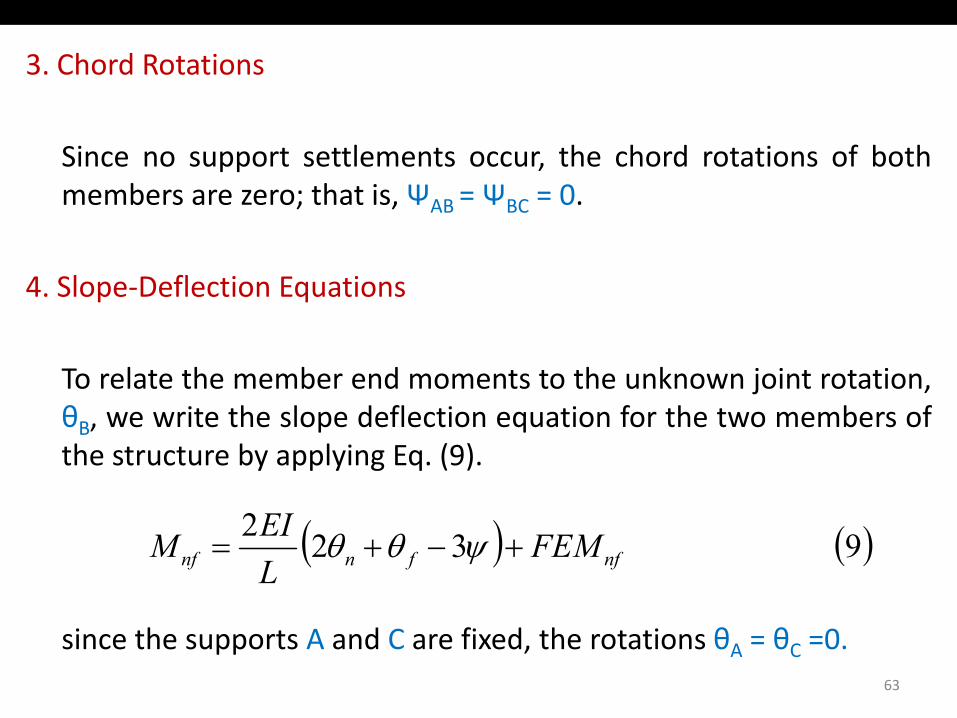
3. Chord Rotations
Since no support settlements occur, the chord rotations of bothmembers are zero; that is, ΨAB = ΨBC = 0.; , AB BC
4. Slope‐Deflection Equations
To relate the member end moments to the unknown joint rotation,θ it th l d fl ti ti f th t b fθB, we write the slope deflection equation for the two members ofthe structure by applying Eq. (9).
( ) ( )9 322nffnnf FEM
LEIM +−+= ψθθ
since the supports A and C are fixed, the rotations θA = θC =0.63
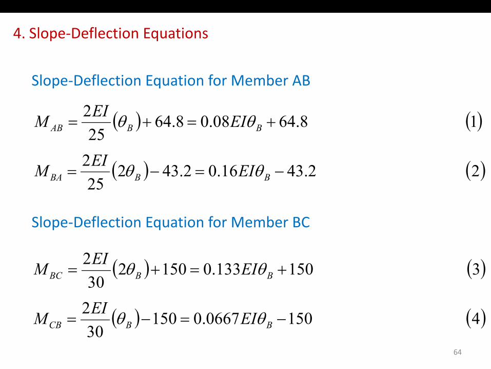
4. Slope‐Deflection Equations
Slope‐Deflection Equation for Member AB
2EI ( ) ( )
2
1 64.808.08.6425
2+=+= BBAB
EI
EIEIM θθ
( ) ( )2 2.3416.02.43225
2−=−= BBBA EIEIM θθ
Slope‐Deflection Equation for Member BC
( ) ( )3501133015022 EIEIM θθ( ) ( )
( ) ( )4150066701502
3 501133.0150230
2+=+= BBBC
EIEIM
EIEIM
θθ
θθ
64
( ) ( )4 1500667.015030
−=−= BBCB EIM θθ
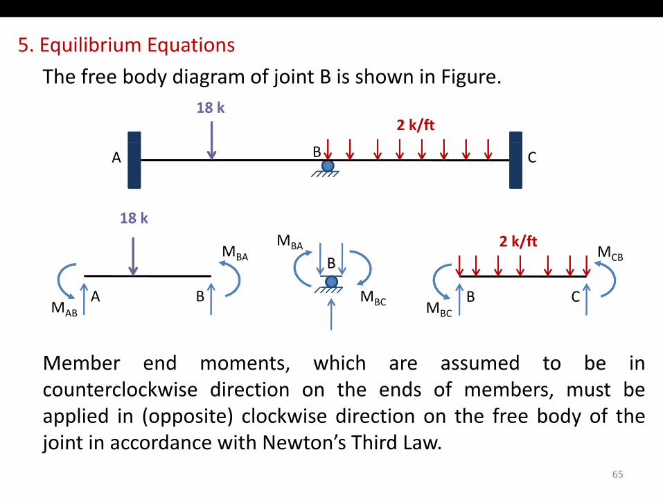
5. Equilibrium Equations
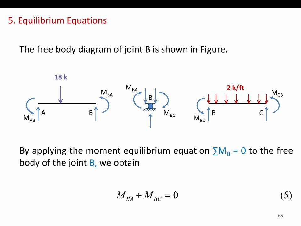
Th f b d di f j i t B i h i FiThe free body diagram of joint B is shown in Figure.
2 k/ft18 k
18 k
B CA
MCBMBA
18 k2 k/ft
BMBA
b d h h d b
B CMBC
A BMAB
MBC
Member end moments, which are assumed to be incounterclockwise direction on the ends of members, must beapplied in (opposite) clockwise direction on the free body of thepp ( pp ) yjoint in accordance with Newton’s Third Law.
65
5. Equilibrium Equations
The free body diagram of joint B is shown in Figure.
MCBMBA
18 k2 k/ft
BMBA
B CMBC
A BMAB
B
MBC
By applying the moment equilibrium equation ∑MB = 0 to the freebody of the joint B we obtainbody of the joint B, we obtain
)5(0+ MM
66
)5( 0=+ BCBA MM
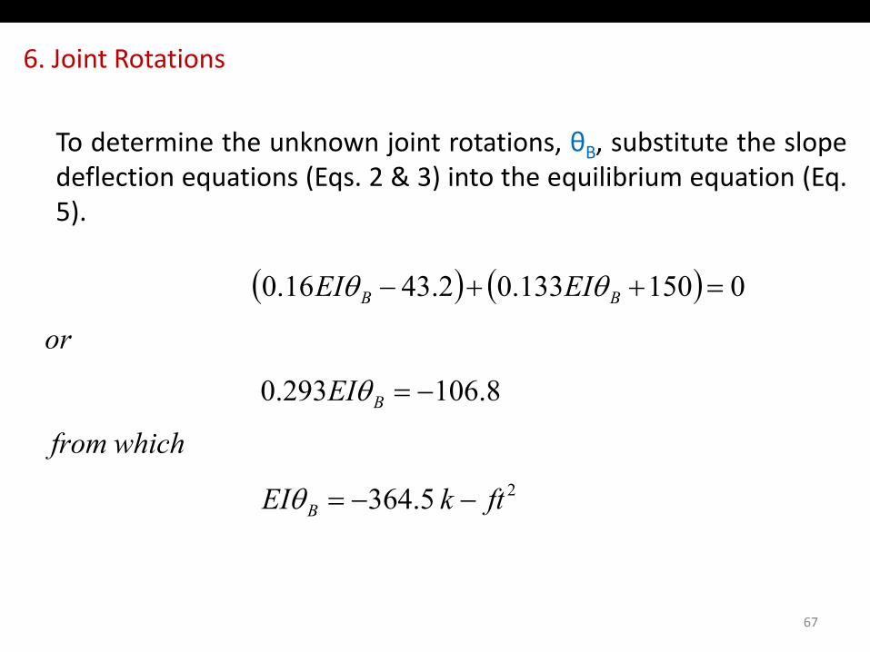
6. Joint Rotations
To determine the unknown joint rotations, θB, substitute the slopedeflection equations (Eqs. 2 & 3) into the equilibrium equation (Eq.q ( q ) q q ( q5).
( ) ( ) 01501330243160 EIEI θθ( ) ( ) 0150133.02.4316.0
or
EIEI BB =++− θθ
8.106293.0
whichfrom
EI B −=θ
2 5.364 ftkEI B −−=θ
67
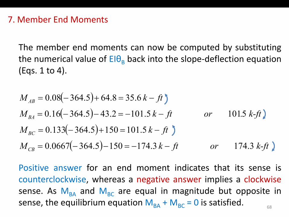
7. Member End Moments
The member end moments can now be computed by substitutingthe numerical value of EIθB back into the slope‐deflection equationB p q(Eqs. 1 to 4).
( )( )( ) 5101 5.1012.435.36416.0
6.358.645.36408.0
k-ft. or ftkM
ftkM
BA
AB
−−=−−=
−=+−=
( )( ) 3.174 3.1741505.3640667.0
5.1011505.364133.0
k-ft or ftkM
ftkM
CB
BC
−−=−−=
−=+−=
Positive answer for an end moment indicates that its sense iscounterclockwise, whereas a negative answer implies a clockwisesense. As MBA and MBC are equal in magnitude but opposite insense, the equilibrium equation MBA + MBC = 0 is satisfied.
68
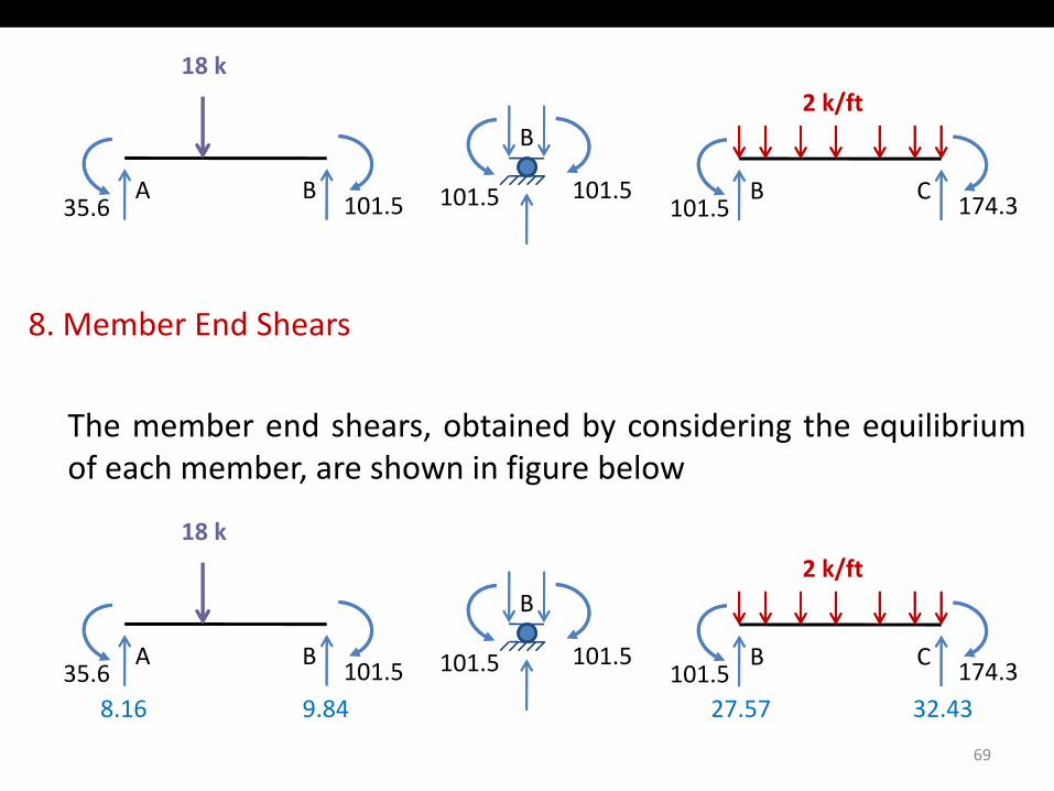
18 k2 k/ft
B C101.5 174.3
A B35.6 101.5
/B
101.5101.5
8. Member End Shears
The member end shears, obtained by considering the equilibriumof each member, are shown in figure below
18 k2 k/ft
B C101 5 174.3
A B35 6 101.5
2 k/ftB
101.5101.5
69
101.5 174.335.6 101.58.16 9.84 27.57 32.43
9. Support Reactions
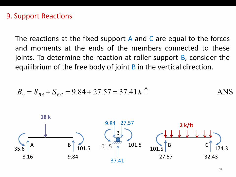
The reactions at the fixed support A and C are equal to the forcesand moments at the ends of the members connected to thesejoints. To determine the reaction at roller support B, consider theequilibrium of the free body of joint B in the vertical direction.
ANS 41.3757.2784.9 ↑=+=+= kSSB BCBAy
18 k2 k/ft9.84 27.57
B C101.5 174.3
A B35.6 101.5
2 k/ftB
101.5101.5
70
8.16 9.84 27.57 32.4337.41
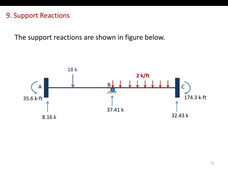
9. Support Reactions
The support reactions are shown in figure below.
/18 k
B CA
2 k/ft
35 6 k ft 174 3 k‐ft
8.16 k
35.6 k‐ft 174.3 k‐ft
32.43 k37.41 k
71
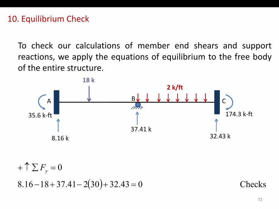
10. Equilibrium Check
To check our calculations of member end shears and supportreactions, we apply the equations of equilibrium to the free body, pp y q q yof the entire structure.
2 k/ft18 k
B CA
2 k/ft
35.6 k‐ft 174.3 k‐ft
8.16 k 32.43 k37.41 k
( )0=∑↑+ yF
72
( ) Checks 043.3230241.371816.8 =+−+−
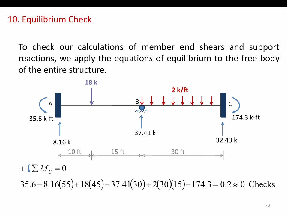
10. Equilibrium Check
To check our calculations of member end shears and supportreactions, we apply the equations of equilibrium to the free body, pp y q q yof the entire structure.
2 k/ft18 k
B CA
2 k/ft
35.6 k‐ft 174.3 k‐ft
8.16 k 32.43 k37.41 k
10 ft 15 ft 30 ft
( ) ( ) ( ) ( )( ) Checks020317415302304137451855168635
0
≈=++
=∑+ CM
10 ft 15 ft 30 ft
73
( ) ( ) ( ) ( )( ) Checks 02.03.174153023041.3745185516.86.35 ≈=−+−+−
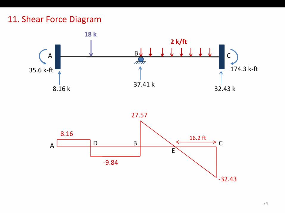
11. Shear Force Diagram
B CA
2 k/ft18 k
8.16 k
35.6 k‐ft 174.3 k‐ft
32.43 k37.41 k
27.57
8.16
A B CE
D16.2 ft
E
‐9.84
‐32.43
74
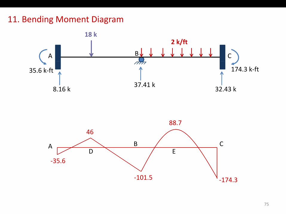
11. Bending Moment Diagram
B CA
2 k/ft18 k
8.16 k
35.6 k‐ft 174.3 k‐ft
32.43 k37.41 k
88 7
A B CED
88.746
‐35.6ED
‐101.5 ‐174.3
75
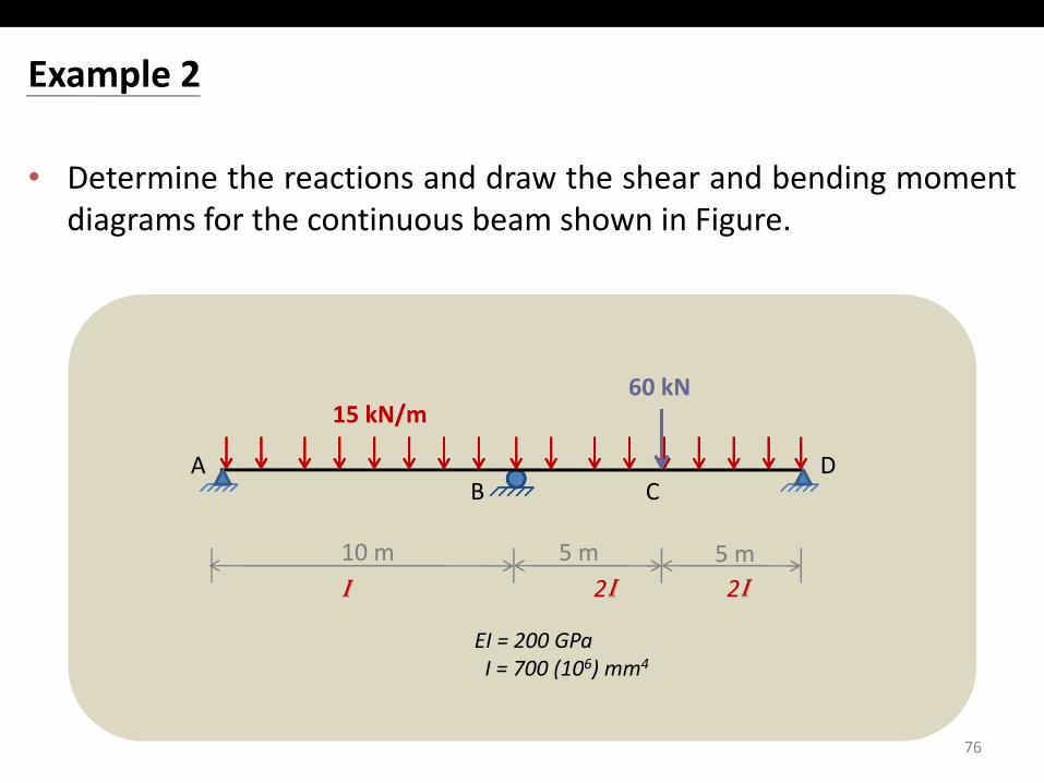
Example 2
• Determine the reactions and draw the shear and bending momentdiagrams for the continuous beam shown in Figurediagrams for the continuous beam shown in Figure.
15 kN/m60 kN
BDA
10 m 5 m
C
5 m
EI = 200 GPaI = 700 (106) mm4
10 m 5 m 5 mI 2I 2I
76
I = 700 (10 ) mm
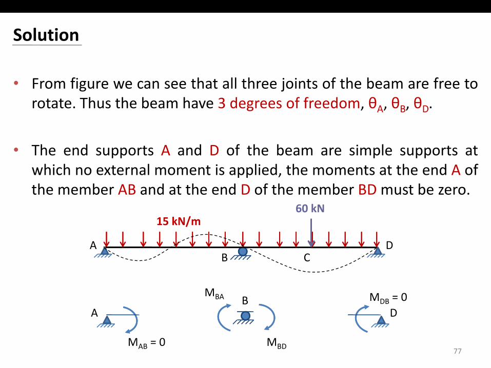
Solution
• From figure we can see that all three joints of the beam are free torotate Thus the beam have 3 degrees of freedom θ θ θrotate. Thus the beam have 3 degrees of freedom, θA, θB, θD.
• The end supports A and D of the beam are simple supports atpp p ppwhich no external moment is applied, the moments at the end A ofthe member AB and at the end D of the member BD must be zero.
60 kN
BDA
15 kN/m60 kN
C
MBA BA
MDB = 0D
77MBDMAB = 0
A D
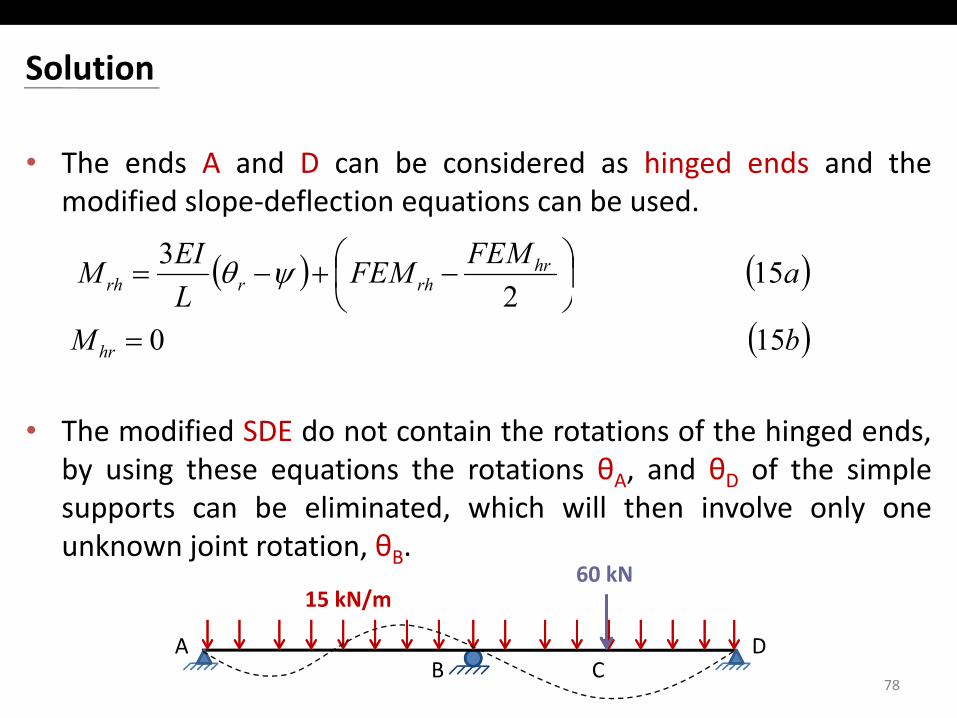
Solution
• The ends A and D can be considered as hinged ends and themodified slope‐deflection equations can be usedmodified slope deflection equations can be used.
( ) ( )aFEMFEMLEIM hr
rhrrh 15 2
3
−+−= ψθ
( )bM hr 15 0=
• The modified SDE do not contain the rotations of the hinged ends,by using these equations the rotations θA, and θD of the simplesupports can be eliminated which will then involve only onesupports can be eliminated, which will then involve only oneunknown joint rotation, θB.
15 kN/m60 kN
78B
DAC
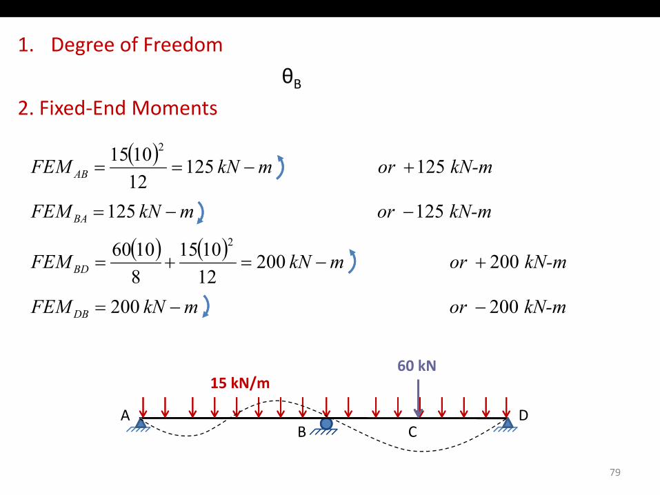
1. Degree of Freedom
θθB
2. Fixed‐End Moments
( )
kN mormkNFEM
kN-mor mkNFEM AB
125125
125 125121015 2
−−=
+−==
( ) ( ) kN-mor mkNFEM
kN-mor mkNFEM
BD
BA
200 200121015
81060
125 1252
+−=+=
−−=
kN-mor mkNFEM DB 200 200128
−−=
DA
15 kN/m60 kN
79
B C
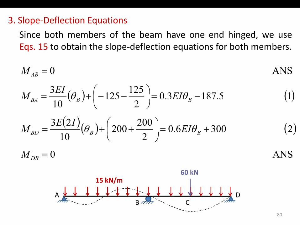
3. Slope‐Deflection Equations
Si b th b f th b h d hi dSince both members of the beam have one end hinged, we useEqs. 15 to obtain the slope‐deflection equations for both members.
( ) ( )15187301251253
ANS 0
−= −−+=
=AB
EIEIM
M
θθ( ) ( )
( ) ( ) ( )23006020020023
1 5.1873.02
12510
+= ++=
−=
−−+= BBBA
EIIEM
EIM
θθ
θθ
( ) ( )
ANS 0
2 3006.02
20010
=
+=
++=
DB
BBBD
M
EIM θθ
DA
15 kN/m60 kN
80
BDA
C
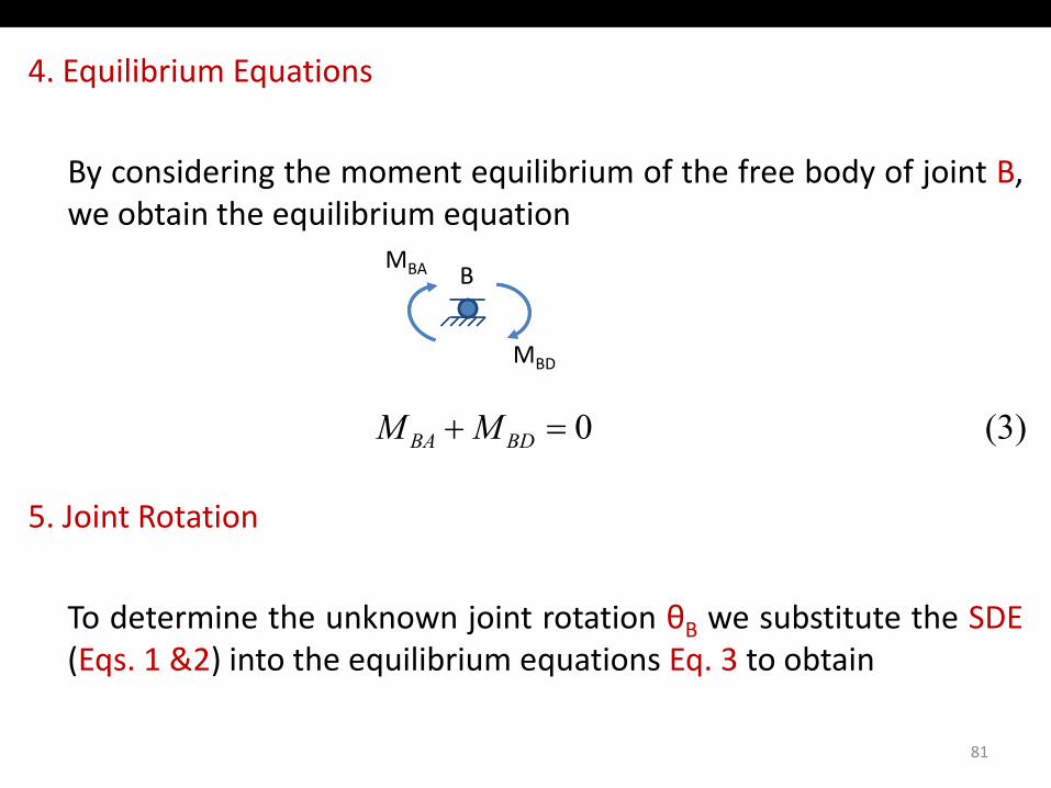
4. Equilibrium Equations
By considering the moment equilibrium of the free body of joint B,we obtain the equilibrium equationq q
MBA B
(3) 0=+ BDBA MM
MBD
5. Joint Rotation
To determine the unknown joint rotation θB we substitute the SDE(Eqs. 1 &2) into the equilibrium equations Eq. 3 to obtain( q ) q q q
81
6. Joint Rotation
( ) ( )( ) ( ) 03006.05.1873.0
or
EIEI BB =++− θθ
5.1129.0
whichfrom
EI B −=θ
2 125 mkNEI B −−=θ
7. Member End Moments
h b d b d b bThe member end moments can now be computed by substitutingthe numerical value of EIθB into the slope‐deflection equations(Eqs. 1 & 2).( q )
82
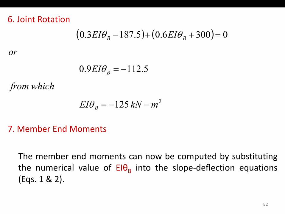
8. Member End Moments
( )( )( ) ANS 2253001256.0
ANS 2252255.1871253.0
mkNM
kN-m or mkNM
BD
BA
−=+−=
−−=−−=
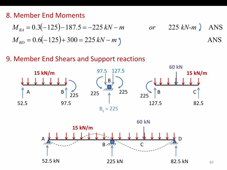
9. Member End Shears and Support reactions
15 kN/m97.5 127.515 kN/m60 kN
B C225
A B225
15 kN/mB
225225
97.515 kN/m
22552.5 97.5 127.5 82.5
By = 225
60 kN
BDA
15 kN/m60 kN
C
83
B C
52.5 kN 225 kN 82.5 kN
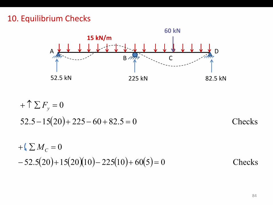
10. Equilibrium Checks60 kN
BDA
15 kN/m60 kN
CB C
52.5 kN 225 kN 82.5 kN
( )0=∑↑+ yF
( ) Checks 05.826022520155.52 =+−+−
0∑+ M
( ) ( )( ) ( ) ( ) Checks 056010225102015205.52
0
=+−+−
=∑+ CM
84
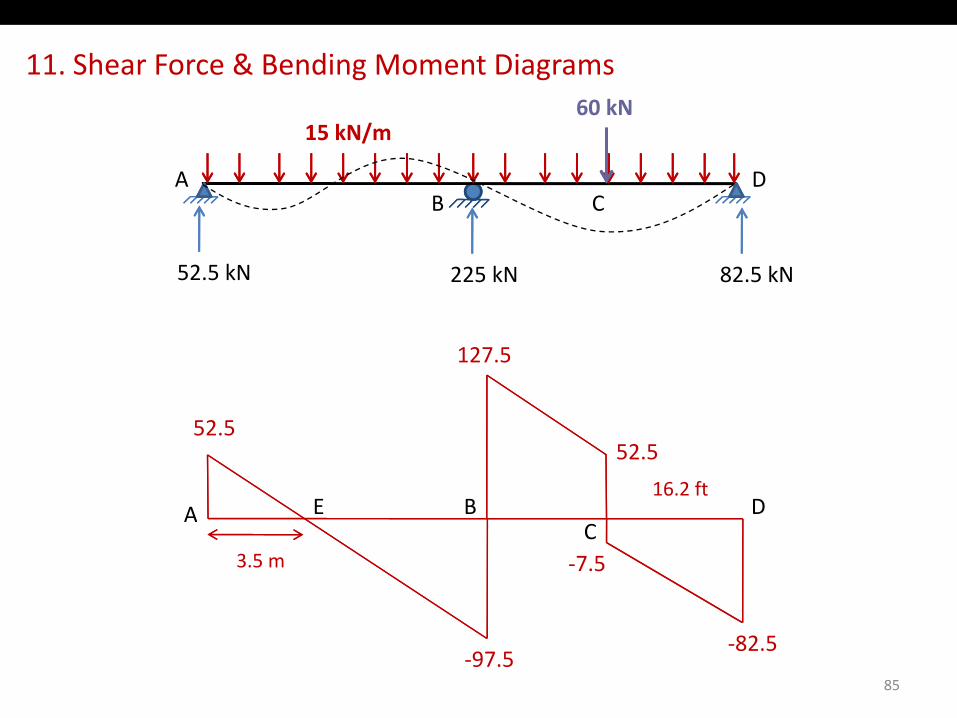
11. Shear Force & Bending Moment Diagrams60 kN
BDA
15 kN/m60 kN
CB C
52.5 kN 225 kN 82.5 kN
127.5
52.5
A B DE16.2 ft
52.5
A B DC
E
‐7.53.5 m
85
‐97.5‐82.5
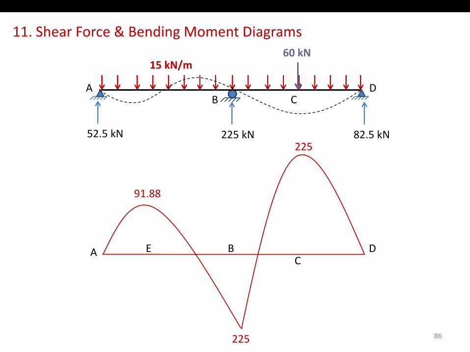
11. Shear Force & Bending Moment Diagrams60 kN
BDA
15 kN/m60 kN
CB C
52.5 kN 225 kN 82.5 kN225
91.88
A B DEA B DC
E
86225
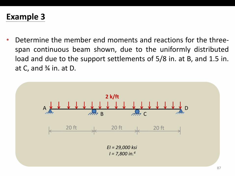
Example 3
• Determine the member end moments and reactions for the three‐span continuous beam shown due to the uniformly distributedspan continuous beam shown, due to the uniformly distributedload and due to the support settlements of 5/8 in. at B, and 1.5 in.at C, and ¾ in. at D.
2 k/ft
BDA
20 f f
C
EI = 29,000 ksi
20 ft 20 ft 20 ft
87
I = 7,800 in.4
Solution
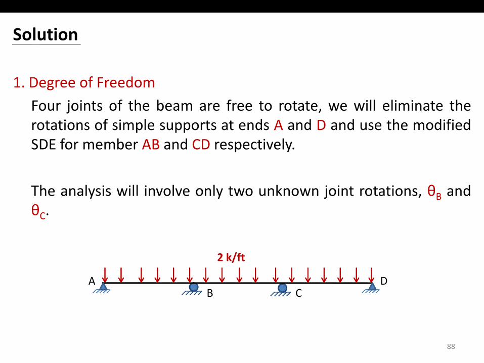
1. Degree of Freedom
Four joints of the beam are free to rotate we will eliminate theFour joints of the beam are free to rotate, we will eliminate therotations of simple supports at ends A and D and use the modifiedSDE for member AB and CD respectively.
The analysis will involve only two unknown joint rotations, θB andθθC.
2 k/ft
BDA
2 k/ft
C
88
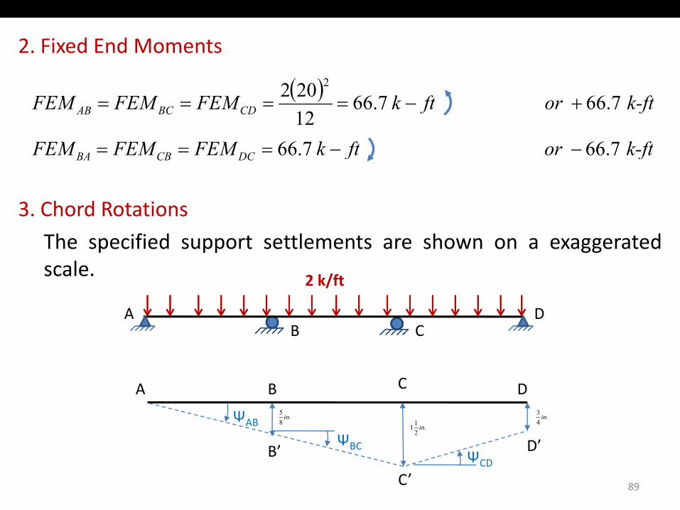
2. Fixed End Moments
( )
k ftftkFEMFEMFEM
k-ftor ftkFEMFEMFEM CDBCAB
766766
7.66 7.6612202 2
+−====
3. Chord Rotations
k-ftor ftkFEMFEMFEM DCCBBA 7.66 7.66 −−===
The specified support settlements are shown on a exaggeratedscale. 2 k/ft
BDA
C
A B C D
ΨAB
Ψ
.85 in
.211 in
.43 in
89
ΨBCΨCD
B’
C’
D’
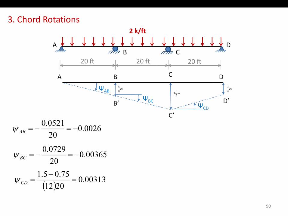
3. Chord Rotations2 k/ft
BDA
2 k/ft
C20 ft 20 ft 20 ft
A B C D
ΨAB.
85 in
11 i.
43 in
20 ft 20 ft 20 ft
ΨBCΨCD
B’
C’
D’.
21 in
05210 0026.0200521.0
−=−=ABψ
0036500729.0==ψ 00365.0
20−=−=BCψ
( ) 00313.02012
75.05.1=
−=CDψ
90
( )2012
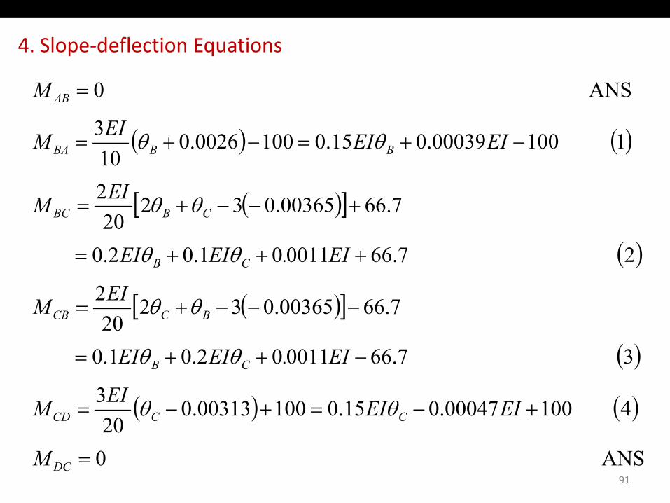
4. Slope‐deflection Equations
( ) ( )1100000390150100002603
ANS 0
−+=−+=
=AB
EIEIEIM
M
θθ( ) ( )
( )[ ] 7.6600365.03220
2
1 10000039.015.01000026.010
+−−+=
+=+=
CBBC
BBBA
EIM
EIEIM
θθ
θθ
( )[ ]
( )2
2 7.66001101.02.0 20
+++= CB
CBBC
EI
EI.EIEI θθ
( )[ ]
( )3766001102010
7.6600365.03220
2
−++=
−−−+= BCCB
EIEIEI
EIM
θθ
θθ
( )
( ) ( )4 10000047.015.010000313.020
3
3 7.66001102.01.0
+−=+−=
++=
CCCD
CB
EIEIEIM
EI.EIEI
θθ
θθ
91
ANS 020
=DCM

5. Equilibrium EquationsM M
(6) 0
(5) 0
=+
=+
CDCB
BCBA
MM
MM
MBC
MBA B
MCD
MCB C
6. Joint Rotations
( )CDCBBC CD
By substituting the slope‐deflection equations (Eqs. 1 – 4) into theequilibrium equations (Eqs. 5 & 6), we obtain
3330006303500 1
3.3300149.01.00.35
−−=+
+−=+
EIEIEI
EIEIEI CB
θθ
θθ
substituting EI = (29,000)(7,800)/(12)2 k‐ft2 into the right sides of
3.3300063.035.00.1 =+ EIEIEI CB θθ
substituting EI (29,000)(7,800)/(12) k ft into the right sides ofthe above equations yields
92
6. Joint Rotations
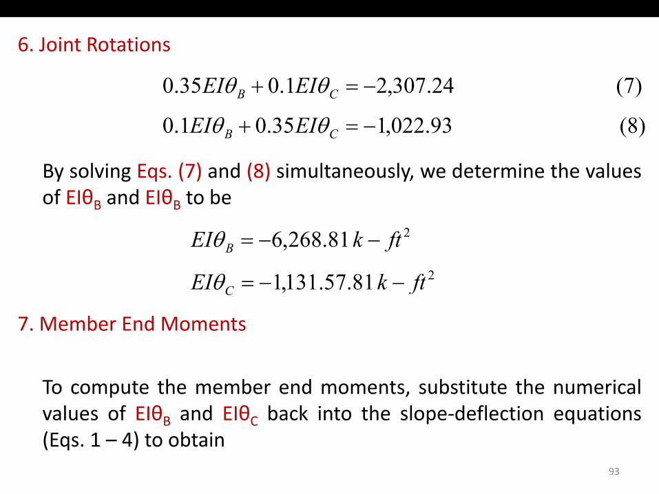
(8) 93.022,135.00.1
(7) 24.307,21.00.35
−=+
−=+
CB
CB
EIEI
EIEI
θθ
θθ
By solving Eqs. (7) and (8) simultaneously, we determine the valuesof EIθB and EIθB to be
2
2
81571311
81.268,6
ftkEI
ftkEI B
=
−−=
θ
θ
7. Member End Moments
81.57.131,1 ftkEI C −−=θ
To compute the member end moments, substitute the numericalvalues of EIθB and EIθC back into the slope‐deflection equationsB C p q(Eqs. 1 – 4) to obtain
93
7. Member End Moments
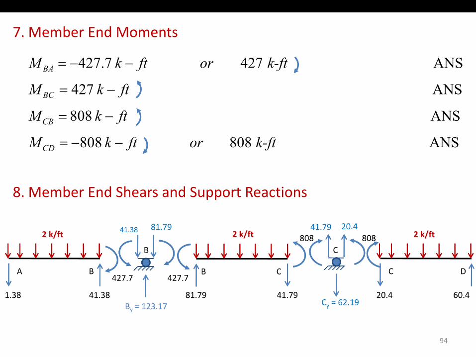
ANS 427
ANS 427 7.427
ftkM
k-ft or ftkM
BC
BA
−=
−−=
ANS 808 808
ANS 808
k-ft or ftkM
ftkM
CD
CB
−−=
−=
8. Member End Shears and Support Reactions
2 k/ft
B
41.38 81.792 k/ft
C808
41.79 20.4808 2 k/ft
B C427.7
A B427.7
1.38 41.38 81.79 41.79B = 123 17 Cy = 62.19
C D
20.4 60.4
94
By = 123.17 y
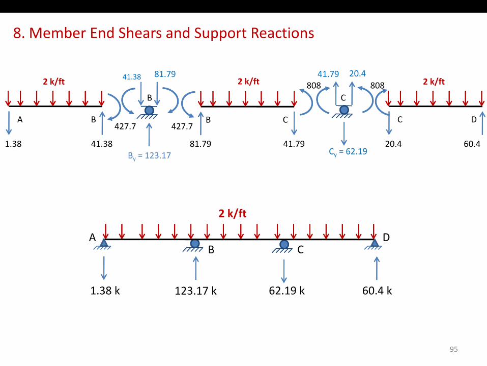
8. Member End Shears and Support Reactions
2 k/ft
B
41.38 81.792 k/ft
C808
41.79 20.4808 2 k/ft
B C427.7
A B427.7
1.38 41.38 81.79 41.79B = 123 17 Cy = 62.19
C D
20.4 60.4By = 123.17 y
k/f
BDA
2 k/ft
C
1.38 k 123.17 k 62.19 k 60.4 k
95
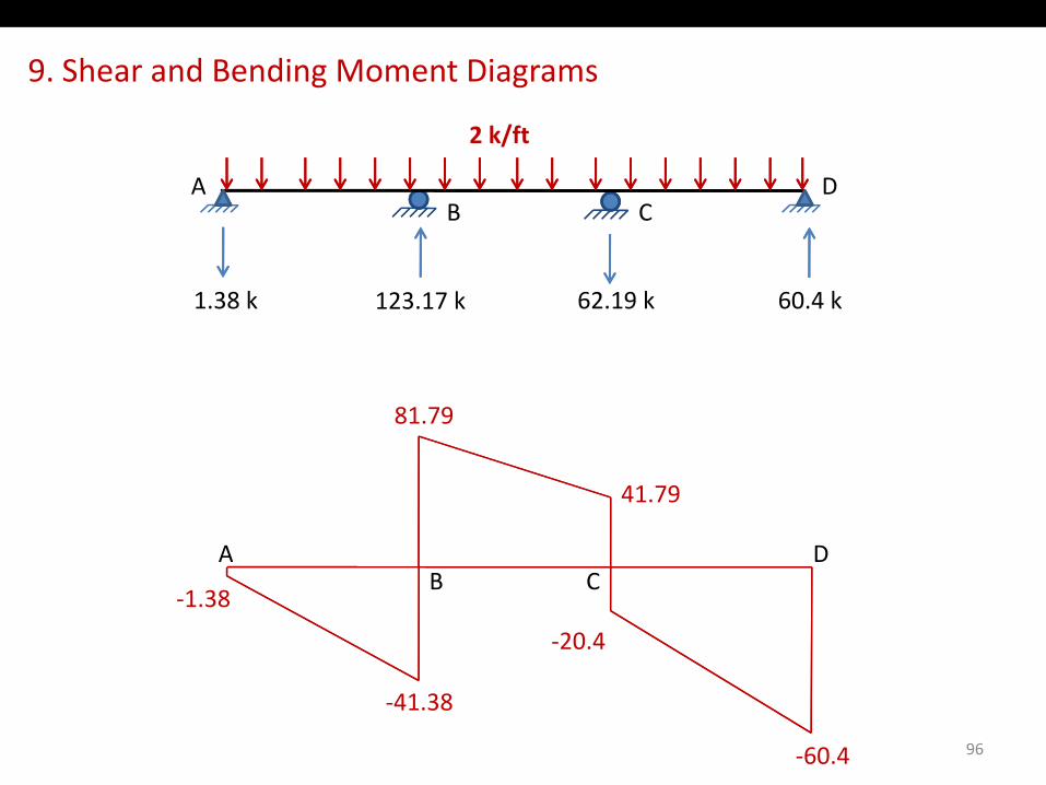
9. Shear and Bending Moment Diagrams
BDA
2 k/ft
C
1.38 k 123.17 k 62.19 k 60.4 k
81.79
A D
41.79
‐1.38
AB
DC
‐20.4
96
‐41.38
‐60.4
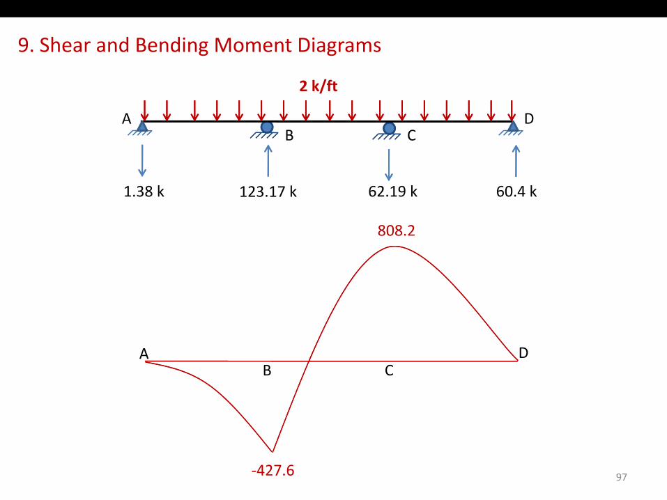
9. Shear and Bending Moment Diagrams
BDA
2 k/ft
C
1.38 k 123.17 k 62.19 k 60.4 k
808.2
A DAB
DC
97‐427.6